brake system - discodan
TRANSCRIPT

BRAKE SYSTEM
–BRAKE SYSTEMBR–1

PRECAUTIONS1. Care must be taken to replace each part properly as it
could affect the performance of the brake system andresult in a driving hazard. Replace the parts with partsof the same part number or equivalent.
2. It is very important to keep parts and the area cleanwhen repairing the brake system.
Parking brake out of adjustmentBinding parking brake wireMaI–adjustment of brake pedal or boosterpush rodTension or return spring faultyBrake line restrictedLining cracked or distortedPad cracked or distortedwheel cylinder or caliper piston sticking
Replace brake shoesReplace padsRepair leakRepair or replace mastercylinderBleed brake systemRepair wheel cylinderRepair cylinderRepair cylinderRepair or replace adjuster
Air in brake systemWheel cylinder faultyBrake cylinder faultyPiston seals worn or damagedRear brake automatic adjuster faulty
Tension or return spring faultyWheel cylinder faultyBrake cylinder faultyPiston frozen in brake cylinderBrake pad sticking
Brake shoes distorted, linings worn orglazedBrake pads distorted, worn or glazedDrum or disc out of round
Inflate tires to proper pressureCheck for cause. Replaceshoes or padsReplace brake shoes
Replace springRepair wheel cylinderRepair cylinderRepair cylinderReplace pads
Replace springRepair as necessaryReplace shoeReplace padRepair as necessary
Linings wornBrake pads wornLeak in brake systemMaster cylinder faulty
BR–19, 36BR–19, 2736BR–27, 44BR–27BR–19, 36BR–19, 36BR–19, 36
Replace adjusterRepair or replace mastercylinder
Adjust parking brakeRepair as necessaryInspect and adjust
Tires improperly inflatedOil or grease on shoes or pads
TROUBLESHOOTING
Adjuster brokenMaster cylinder faulty
BR–7BR–27BR–19, 36BR–19, 36
Replace padsReplace drum or disc
BR–27BR–19, 36BR–19, 2736
Low or spongy pedal BR–27BR–19, 36
Possible cause
Brakes drag
Brakes pull
BR–27, 44
BR–6,17
RemedyProblem
BR–27
Page
BR–8
BR–9
BR–9
–BRAKE SYSTEM PrecautionsBR–2

(Drum brake)Brake shoes binding at backing plateledgesBacking plate ledges wornLoose or missing shoes hold–down springLoose set bolt at backing plate(Disc brake)Loose or missing pad support plateLoose installation bolt
Oil or grease on shoes or padsBrake shoes distorted, linings worn orglazed, drums worn
Brake pads distorted, worn or glazedPiston frozen in brake cylinderBrake booster faultyVacuum leaksBrake line restricted
Check for cause. Replaceshoes or padsReplace brake shoes
Replace padsRepair cylinderRepair boosterRepair as necessaryRepair as necessary
Caliper to wheel or rotor interferenceDust cover to rotor or backing plate todrum interferenceOther brake system components faultyTires rubbing against chassis and/or body
Replace and lubricate ledgesReplace shoes hold–down springTighten
Replace or refinish drums orrotors if heavily scoredReplace as requiredCorrect or replace
TROUBLESHOOTING (Cont’d)
Repair or replace as necessaryRepair as necessary
Replace pad support plateTighten
Scraping or grindingnoise when brakesare applied
Snapping or clickingnoise when brakesare applied
BR–19, 2736BR–19, 36BR–19, 2736
BR–19, 36BR–19, 36BR–15
Hard pedal butbrakes inefficient
BR–19, 2736BR–27
Worn brake linings or pads
BR–19, 36BR–19, 36
BR–27BR–27BR–27
Possible cause
Lubricate
Problem Remedy
BR–27
Page
–BRAKE SYSTEM TroubleshootingBR–3

Improper positioning of pad in caliperRotor rubbing against caliper housingImproper installation of disc brake padsupport plate(Drum brake or parking brake)Weak, damaged or incorrect shoe holddown springsGrooved backing plate ledgesBent or warped backing plate causinginterference with drumImproper machining of drum causinginterference with backing plate or shoeOther brake system components:Loose or extra parts in brakesRear drum adjustment too tight causinglining to glazeWorn, damaged or insufficientlylubricated wheel bearings
Brake drums and linings, rotors and padsworn or scoredDirty, greased, contaminated or glazedlinings or padsImproper linings or pads using
MaI–adjustment of brake pedal or boosterpush rod(Disc brake)Missing or damaged brake pad anti–squealshimBurred or rusted calipers(Drum brake)Weak damaged or incorrect shoe hold downsprings, loose or damaged shoehold–down spring pins and springs andgrooved backing plate ledges
Squeaking, squealinggroaning or chatteringnoise whenbrakes are appliedNote: Brake frictionmaterials inherentlygenerate noise andheat in order to dissipateenergy. As aresult, occasionalsqueal is normal andis aggravated by severeenvironmentalconditions such ascold, heat, wetness,snow, salt, mud, etc.This occasionalsqueal is not a functionalproblem anddoes not indicate anyloss of brakeeffectiveness
MaI–adjustment of brake pedal or boosterpush rodPoor return of brake booster or mastercylinder or wheel cylinder(Disc brake)Rusted or stuck piston
TROUBLESHOOTING (Cont’d)
Inspect and lubricate asnecessaryRepair or replaceRepair or replaceRepair or replace
Inspect for correct usage orreplaceInspect and adjust
BR–19, 2736BR–19, 2736BR–19, 2736BR–6,17
Squealing andsqueaking noisewhen brakes are notapplied
Inspect, repair or replace asnecessary
Repair or replaceRepair or replace
BR–19, 36BR–19, 36BR–19, 36
Inspect, repair or replace
Inspect, repair or replace
Inspect, repair or replace
BR–27, 44BR–27, 44
Inspect and adjust
Clean or replace
Possible cause
BR–9,1527
Clean or deburr
Replace drum
BR–27, 44
BR–36
BR–27, 44
BR–19, 36
BR–19, 36
BR–6,17
RemedyProblem
Replace
Replace
BR–27
Page
–BRAKE SYSTEM TroubleshootingBR–4

MaI–adjustment of brake pedal or boosterpush rodWorn, damaged or dry wheel bearings(Disc brake)Loose or missing anti–rattle spring or padsupport plate or crimping on outer padFailure of shimWear on slide bushingLoose installation boltPoor return of piston(Drum brake or parking brake)Loose or extra parts
Inspect, replace if necessaryInspect, replace if necessaryInspect, tighten is necessaryInspect, repair or replace
Stones or foreign material trapped insidewheel coversLoose wheel nuts Tighten to correct torque
Replace if stud holes areelongatedInspect and adjust
TROUBLESHOOTING (Cont’d)
Groaning, clicking orrattling noise whenbrakes are notapplied
BR–19, 36BR–19, 36BR–19, 36BR–19, 36
Inspect and lubricate or replace
Inspect, repair or replace
Remove foreign material
Inspect and repair
Possible cause
BR–19, 36
BR–27, 44
Problem
BR–6,17
Remedy Page
–BRAKE SYSTEM TroubleshootingBR–5
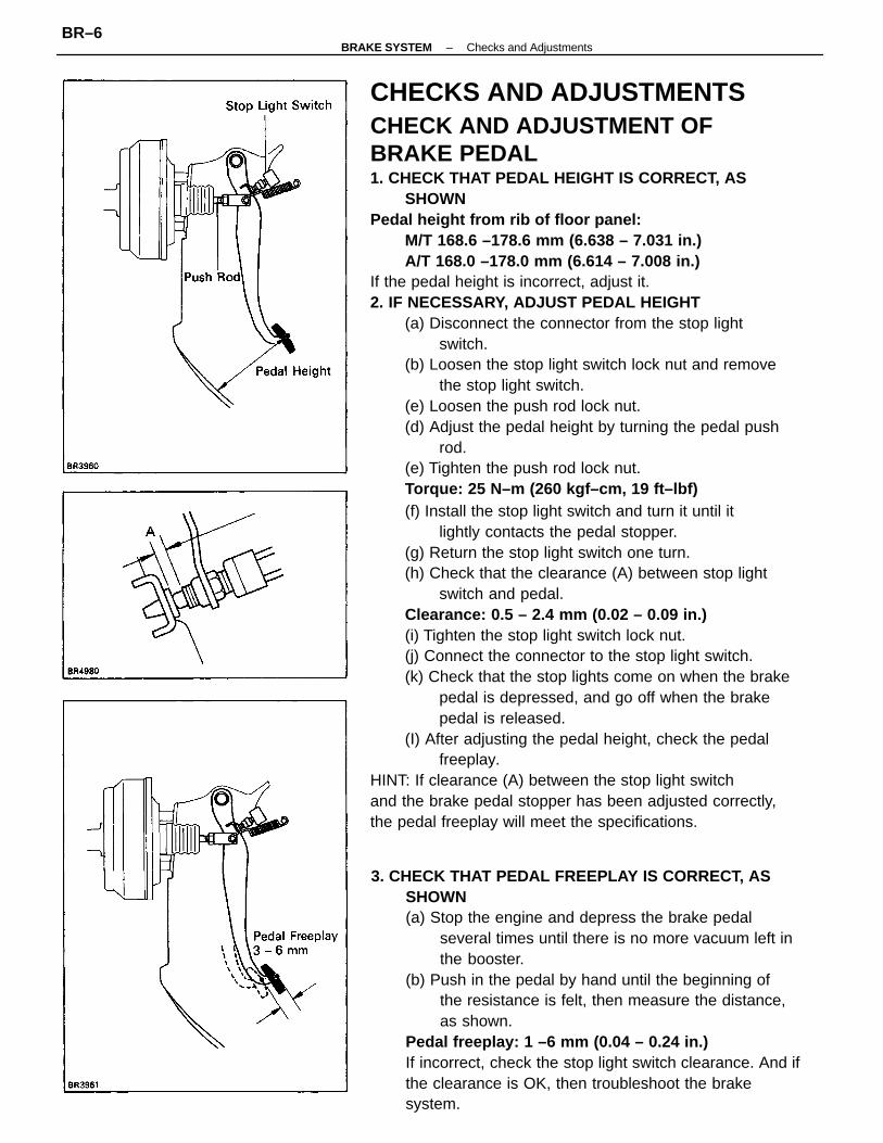
CHECKS AND ADJUSTMENTSCHECK AND ADJUSTMENT OFBRAKE PEDAL1. CHECK THAT PEDAL HEIGHT IS CORRECT, AS
SHOWNPedal height from rib of floor panel:
M/T 168.6 –178.6 mm (6.638 – 7.031 in.)A/T 168.0 –178.0 mm (6.614 – 7.008 in.)
If the pedal height is incorrect, adjust it.2. IF NECESSARY, ADJUST PEDAL HEIGHT
(a) Disconnect the connector from the stop lightswitch.
(b) Loosen the stop light switch lock nut and removethe stop light switch.
(e) Loosen the push rod lock nut.(d) Adjust the pedal height by turning the pedal push
rod.(e) Tighten the push rod lock nut.Torque: 25 N–m (260 kgf–cm, 19 ft–lbf)(f) Install the stop light switch and turn it until it
lightly contacts the pedal stopper.(g) Return the stop light switch one turn.(h) Check that the clearance (A) between stop light
switch and pedal.Clearance: 0.5 – 2.4 mm (0.02 – 0.09 in.)(i) Tighten the stop light switch lock nut.(j) Connect the connector to the stop light switch.(k) Check that the stop lights come on when the brake
pedal is depressed, and go off when the brakepedal is released.
(I) After adjusting the pedal height, check the pedalfreeplay.
HINT: If clearance (A) between the stop light switchand the brake pedal stopper has been adjusted correctly,the pedal freeplay will meet the specifications.
3. CHECK THAT PEDAL FREEPLAY IS CORRECT, ASSHOWN(a) Stop the engine and depress the brake pedal
several times until there is no more vacuum left inthe booster.
(b) Push in the pedal by hand until the beginning ofthe resistance is felt, then measure the distance,as shown.
Pedal freeplay: 1 –6 mm (0.04 – 0.24 in.)If incorrect, check the stop light switch clearance. And ifthe clearance is OK, then troubleshoot the brakesystem.
–BRAKE SYSTEM Checks and AdjustmentsBR–6

2. AIR TIGHTNESS(a) Start the engine and stop it after one or two minutes.
Depress the brake pedal several times slowly. If thepedal goes down the farthest the first time, butgradually rises after the second or third time, thebooster is air tight.
(b) Depress the brake pedal while the engine is running,and stop the engine with the pedal depressed. Ifthere is no change in the pedal reserve travel afterholding the pedal for thirty seconds, the booster isair tight.
BLEEDING OF BRAKE SYSTEMHINT: If any work is done on the brake system or if airin the brake lines is suspected, bleed the system of air.NOTICE: Do not let brake fluid remain on a paintedsurface. Wash it off immediately.1. FILL BRAKE RESERVOIR TANK WITH BRAKE FLUIDFluid: SAEJ1703 or FMVSS No. 116 DOT3
4. CHECK THAT PEDAL RESERVE DISTANCE ISCORRECT, AS SHOWN
Release the parking brake.With the engine running, depress the pedal and measurethe pedal reserve distance, as shown.Pedal reserve distance from asphalt sheet at 490 N(50 kgf, 110.2 lbf):
w/o ABS More than 85 mm (3.35 in.)w/ ABS More than 90 mm (3.54 in.)
If the reserve distance is incorrect, troubleshoot the brakesystem.
OPERATIONAL TEST OF BRAKE BOOSTER1. OPERATING CHECK
(a) Depress the brake pedal several times with the engine off andcheck that there is no change in thepedal reserve distance.
(b) Depress the brake pedal and start the engine. If thepedal goes down slightly, operation is normal.
2. BLEED MASTER CYLINDERHINT: If the master cylinder has been disassembled orif the reservoir tank becomes empty, bleed the air fromthe master cylinder.
(a) Disconnect the brake tubes from the master cylinder.(b) Slowly depress the brake pedal and hold it.
–BRAKE SYSTEM Checks and AdjustmentsBR–7

CHECK AND ADJUSTMENT OFPARKING BRAKE1. CHECK THAT PARKING BRAKE LEVER TRAVEL IS
CORRECTPull the parking brake lever all the way up, and count thenumber of clicks.Parking brake lever travel
at 796 N (20 kgf, 44.1 lbf): 4 – 7 clicksIf incorrect, adjust the parking brake.2. IF NECESSARY, ADJUST PARKING BRAKEHINT: Before adjusting the parking brake, make surethat the rear brake shoe clearance has been adjusted.For shoe clearance adjustment, see step 8 to 9 on pagesBR–34 and BR–35, step 8 on page BR–50.
(a) Remove the console box.(b) Loosen the lock nut and turn the adjusting nut until
the lever travel is correct.(c) Tighten the lock nut.Torque: 5.4 N–m (55 kgf–cm, 48 in.–lbf)(d) Install the console box.
3. BLEED BRAKE LINE(a) Connect the vinyl tube to the brake cylinder.(b) Depress the brake pedal several times, then loosen
the bleeder plug with the pedal held down.(c) At the point when fluid stops coming out, tighten
the bleeder plug, then release the brake pedal.(d) Repeat (b) and (c) until all the air in the fluid has
been bled out.(e) Repeat the above procedure to bleed the air out of
the brake line for each wheel.4. CHECK FLUID LEVEL IN RESERVOIR TANKCheck the fluid level and add fluid if necessary.Fluid: SAEJ1703 or FMVSS No. 116 DOT3
(c) Block off the outlet plug with your finger and re-lease the brake pedal.
(d) Repeat (b) and (c) three or four times.
–BRAKE SYSTEM Checks and AdjustmentsBR–8

1. REMOVE AIR CLEANER ASSEMBLY2. REMOVE ENGINE WIRE BRACKET3. DISCONNECT LEVEL WARNING SWITCH
CONNECTOR4. DRAW OUT FLUID WITH SYRINGE
NOTICE: Do not let brake fluid remain on a paintedsurface. Wash it off immediately.
5. DISCONNECT BRAKE TUBESUsing SST, disconnect the brake tubes from the mastercylinder.SST 09751–360116. REMOVE MASTER CYLINDERRemove the mounting nuts and pull out the master cylinderand gasket.
MASTER CYLINDERREMOVAL OF MASTER CYLINDER
–BRAKE SYSTEM Master CylinderBR–9
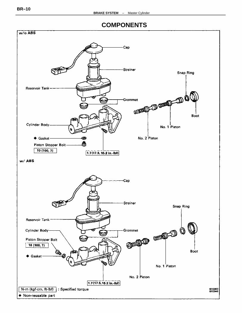
COMPONENTS
–BRAKE SYSTEM Master CylinderBR–10

6. REMOVE TWO PISTONS(a) Push in the piston with a screwdriver and remove
the snap ring with snap ring pliers.(b) Remove the No.1 piston and spring by hand, pulling
straight out, not at an angle.NOTICE: If pulled out at an angle, there is possibilitythat the cylinder bore could be damaged.
2. REMOVE RESERVOIR TANK(a) Remove the set screw and pull out the reservoir
tank.(b) Remove the cap and strainer from the reservoir tank.
3. REMOVE TWO GROMMETS4. PLACE CYLINDER IN VISE
(c) Place a rag and two wooden blocks on the worktable and lightly tap the cylinder flange againstthe block edges until the piston drops out of thecylinder.
HINT: Make sure the distance (A) from the rag to thetop of the blocks is at least 100 mm (3.94 in.).
5. REMOVE PISTON STOPPER BOLTUsing a screwdriver, push the pistons in all the way andremove the piston stopper bolt and gasket.HINT: Tape the screwdriver tip before use.
DISASSEMBLY OF MASTER CYLINDER1. REMOVE MASTER CYLINDER BOOTUsing a screwdriver, remove the master cylinder boot.
–BRAKE SYSTEM Master CylinderBR–11

2. INSTALL TWO PISTONSNOTICE: Be careful not to damage the rubber lips onthe pistons.(a) Insert the two pistons straight in, not at an angle.NOTICE: If inserted at an angle, there is a possibilitythat the cylinder bore could be damaged.(b) Push in the piston with a screwdriver and install the
snap ring with snap ring pliers.HINT: Tape the screwdriver tip before use.
INSPECTION OF MASTER CYLINDERCOMPONENTSHINT: Clean the disassembled parts with compressedair.1. INSPECT CYLINDER BORE FOR RUST OR SCORING2. INSPECT CYLINDER FOR WEAR OR DAMAGEIf necessary, clean or replace the cylinder.
3. INSTALL PISTON STOPPER BOLTUsing a screwdriver, push the piston in all the wayand install the piston stopper bolt over the gasket.Torque the bolt.Torque: 10 N–m (100 kgf–cm, 7 ft–lbf)
4. INSTALL TWO GROMMETS
ASSEMBLY OF MASTER CYLINDER(See page BR–10)1. APPLY LITHIUM SOAP BASE GLYCOL GREASE TO
RUBBER PARTS INDICATED BY ARROWS
–BRAKE SYSTEM Master CylinderBR–12

5. INSTALL RESERVOIR TANK(a) Install the cap and strainer to the reservoir tank.(b) Push the reservoir tank onto the cylinder.(c) Install the set screw while pushing on the reservoir
tank.Torque: 1.7 N–m (17.5 kgf–cm, 15.2in–Ibf)
6. INSTALL MASTER CYLINDER BOOTWith the U P mark on the master cylinder boot facingupwards, install the cylinder boot on the master cylinder.
–BRAKE SYSTEM Master CylinderBR–13

4. CONNECT LEVEL WARNING SWITCH CONNECTOR5. INSTALL ENGINE WIRE BRACKET6. INSTALL AIR CLEANER ASSEMBLY7. FILL BRAKE RESERVOIR WITH BRAKE FLUID AND
BLEED BRAKE SYSTEM(See page BR–7)8. CHECK FOR FLUID LEAKAGE9. CHECK AND ADJUST BRAKE PEDAL(See page BR–6)
INSTALLATION OF MASTERCYLINDER(See page BR–9)1. ADJUST LENGTH OF BRAKE BOOSTER PUSH ROD
BEFORE INSTALLING MASTER CYLINDER(See page BR–17)
3. CONNECT TWO BRAKE TUBESUsing SST, connect the brake tubes to the master cylinder.Torque the union nuts.SST 09751–36011Torque: 15 N–m (155 kgf–cm, 11 ft–Ibf)
2. INSTALL MASTER CYLINDERInstall the master cylinder and gasket on the brakebooster with three nuts.Torque: 13 N–m (130 kgf–cm, 9 ft–lbf)
–BRAKE SYSTEM Master CylinderBR–14
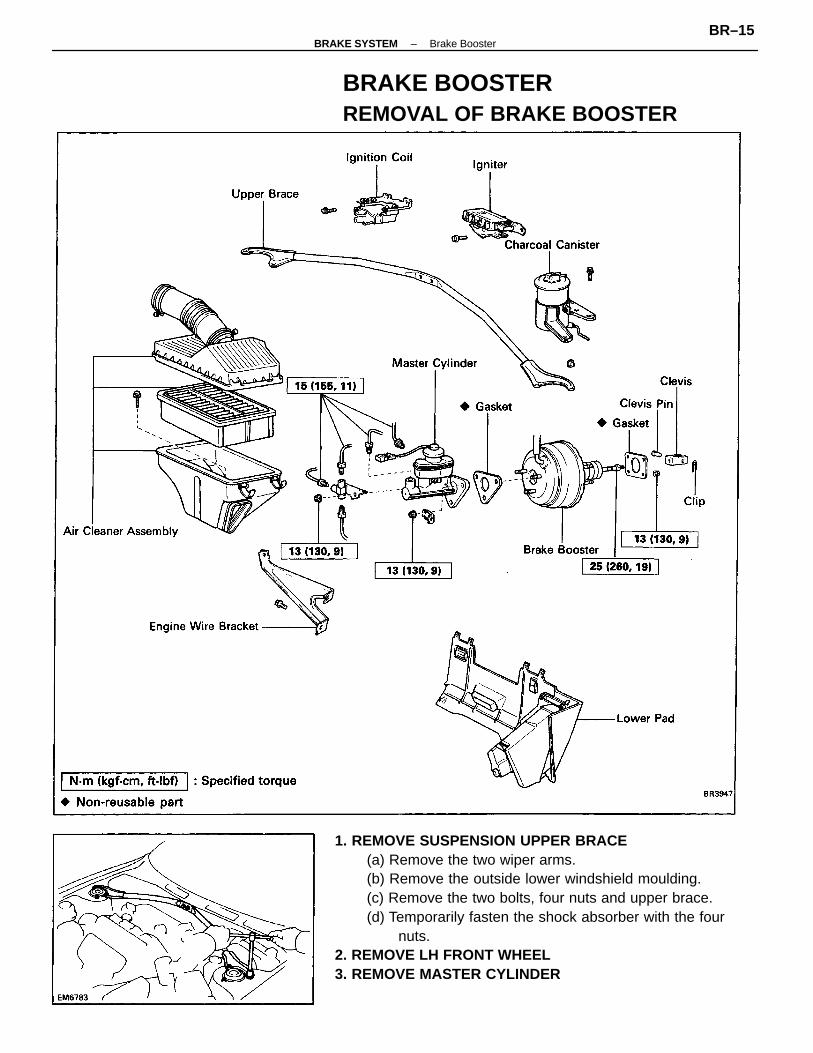
1. REMOVE SUSPENSION UPPER BRACE(a) Remove the two wiper arms.(b) Remove the outside lower windshield moulding.(c) Remove the two bolts, four nuts and upper brace.(d) Temporarily fasten the shock absorber with the four
nuts.2. REMOVE LH FRONT WHEEL3. REMOVE MASTER CYLINDER
BRAKE BOOSTERREMOVAL OF BRAKE BOOSTER
–BRAKE SYSTEM Brake BoosterBR–15

4. REMOVE CHARCOAL CANISTER5. REMOVE LOWER PAD6. REMOVE VACUUM HOSE7. REMOVE PEDAL RETURN SPRING8. REMOVE CLIP, CLEVIS PIN AND CLEVIS
10. REMOVE BRAKE BOOSTER(a) Using SST and spanner, disconnect the brake tube
from the flexible hose of LH front brake.SST 09751–36011
(b) Remove the brake tube grommet from the body.
9. REMOVE IGNITION COIL AND IGNITER(a) Remove the ignition coil with the bracket.(b) Remove the vacuum tube installation bolt.(c) Remove the igniter with the bracket.
(c) (w/ ABS)Remove the three brake tubes as shown in theillustration from the No. 1 brake tube clamp.
(d) Remove the four nuts.(e) Remove the booster and gasket.
–BRAKE SYSTEM Brake BoosterBR–16

INSTALLATION OF BRAKE BOOSTER(See page BR–15)1. INSTALL BRAKE BOOSTER
(a) Install booster and gasket.(b) Install the clevis to the operating rod.(c) Install and torque the booster installation nuts.Torque: 13 N–m (130 kgf–cm, 9 ft–lbf)(d) Insert the clevis pin into the clevis and brake pedal,
and install the clip to the clevis pin.(e) Install the pedal return spring.(f) (w/ ABS)
Install the three brake tubes to the No. 1 brake tubeclamp.
(c) Turn the SST upside down, and set it on the booster.SST 09737–00010
(d) Measure the clearance between the booster pushrod and pin head (SST).
Clearance: 0 mm (0 in.)(e) Adjust the booster push rod length until the push
rod lightly touches the pin head.HINT: When adjusting the push rod, depress thebrake pedal enough so that the push rod sticks out.
(g) Using SST and spanner, connect the brake tube tothe flexible hose of LH front brake.SST 09751–36011
Torque: 15 N–m (155 kgf–cm, 11 ft–lbf)(h) Install the brake tube grommet to the body.
2. ADJUST LENGTH OF BOOSTER PUSH ROD(a) Install the gasket on the master cylinder.(b) Set the SST on the gasket, and lower the pin until its
tip slightly touches the piston.SST 09737–00010
–BRAKE SYSTEM Brake BoosterBR–17

4. INSTALL VACUUM HOSE5. INSTALL MASTER CYLINDER(See page BR–9)6. FILL BRAKE RESERVOIR WITH BRAKE FLUID AND
BLEED BRAKE SYSTEM(See page BR–7)7. CHECK FOR FLUID LEAKAGE8. CHECK AND ADJUST BRAKE PEDAL(See page BR–6)Check and adjust the brake pedal, then tighten the clevislock nut.Torque: 25 N–m (260 kgf–cm, 19 ft–Ibf)9. PERFORM OPERATIONAL CHECK(See page BR–7)10. INSTALL LOWER PAD11. INSTALL LEFT SIDE FRONT WHEEL
12. INSTALL SUSPENSION UPPER BRACE(a) Remove the four nuts from the shock absorber.(b) Install the suspension upper brace with the two
bolts and four bolts.Torque: Bolt 21 N–m (210 kgf–cm, 75 ft–lbf)Nut 37 N–m (375 kgf–cm, 27 ft–lbf)(c) Install the outside lower windshield moulding.(d) Install the two wiper arms.
3. INSTALL IGNITER AND IGNITION COIL(a) Install the igniter with the bracket.(b) Install the vacuum tube installation bolt.(c) Install the ignition coil with the bracket.
–BRAKE SYSTEM Brake BoosterBR–18

REPLACEMENT OF BRAKE PADSHINT: If a squealing noise is made by the front brakeswhile driving, check the pad wear indicator. If there isevidence of the indicator contacting the rotor disc, thebrake pad should be replaced.
1. REMOVE FRONT WHEELRemove the wheel and temporarily fasten the rotor discwith the hub nuts.
FRONT BRAKECOMPONENTS
–BRAKE SYSTEM Front BrakeBR–19

4. REMOVE FOLLOWING PARTS:(a) Two anti–squeal springs(b) Two brake pads(c) Three anti–squeal shims(d) Pad wear indicator plate(e) Four pad support plates
5. CHECK ROTOR DISC THICKNESS(See step 2 on page BR–24)6. CHECK ROTOR DISC RUNOUT(See step 3 on page BR–24)7. INSTALL PAD SUPPORT PLATESInstall the four pad support plates.
2. INSPECT PAD LINING THICKNESSCheck the pad thickness through the cylinder inspectionhole and replace the pads if it is not within specification.Minimum thickness: 1.0 mm (0.039 in.)
(b) Remove the brake cylinder and suspend it so thehose is not stretched.
HINT: Do not disconnect the brake hose.
3. REMOVE CYLINDER FROM TORQUE PLATE(a) Remove two installation bolts from the torque plate.
–BRAKE SYSTEM Front BrakeBR–20

9. INSTALL CYLINDER(a) Draw out a small amount of brake fluid from the
reservoir tank.(b) Press in the piston with a hammer handle or an
equivalent.HINT: If the piston is heavy and difficult to push in,loosen the bleeder plug and push in the piston whileletting some brake fluid escape.
8. INSTALL NEW PADS(a) Install a pad wear indicator plate on the inside pad.(b) Apply disc brake grease to both sides of the inner
anti–squeal shim.(c) Install the two anti–squeal shims to the outside pad.(d) Install the anti–squeal shim to the inside pad.
(e) Install inside pad with the pad wear indicator platefacing upward.
(f) Install outside pad.NOTICE: There should be no oil or grease adheringto the friction surfaces of the pads or the rotor disc.(g) Install the two anti–squeal springs.
(c) Install the brake cylinder.(d) Install and torque the two installation bolts.Torque: 39 N–m (400 kgf–cm, 29 ft–lbf)
10. INSTALL FRONT WHEEL11. CHECK THAT FLUID LEVEL IS MAX LINE
–BRAKE SYSTEM Front BrakeBR–21

REMOVAL OF CYLINDER(See page BR–19)1. DISCONNECT FLEXIBLE HOSE
(a) Remove the union bolt and two gaskets from thebrake cylinder, then disconnect the flexible hosefrom the brake cylinder.
(b) Use a container to catch the brake fluid as it drainsout.
3. REMOVE FOLLOWING PARTS:(a) Two anti–squeal springs(b) Two brake pads(c) Three anti–squeal shims(d) Pad wear indicator(e) Four pad support plates
2. REMOVE CYLINDER FROM TORQUE PLATERemove the two installation bolts and cylinder.
–BRAKE SYSTEM Front BrakeBR–22

3. REMOVE PISTON FROM CYLINDER(a) Put a piece of cloth or an equivalent between the
piston and the cylinder.(b) Use compressed air to remove the piston from the
cylinder.CAUTION: Do not place your fingers in front of thepiston when using compressed air.
DISASSEMBLY OF CYLINDER(See page BR–19)1. REMOVE FOLLOWING PARTS:
(a) Two sliding bushings(b) Four dust boots
2. REMOVE CYLINDER BOOT SET RING AND CYLINDERBOOT
Using a screwdriver, remove the cylinder boot set ringand cylinder boot.
4. REMOVE PISTON SEAL FROM BRAKE CYLINDERUsing a screwdriver, remove the piston seal.
–BRAKE SYSTEM Front BrakeBR–23

3. MEASURE ROTOR DISC RUNOUTHINT: Before measuring the runout, confirm that thefront hub bearing play is within specification.Measure the rotor disc runout at 10 mm (0.39 in.) fromthe outer edge of the rotor disc.Maximum disc runout: 0.07 mm (0.0028 in.)If the runout is greater than the maximum, inspect andadjust if following the procedure below.Then replace the disc if necessary.
(a) Remove the torque plate from the knuckle.(b) Remove the hub nuts of the temporarily installed
disc and pull off the rotor disc.(c) Check that the hub axial play is within specification,
and replace the bearing if not within specification.(See page SA–8)
(d) Install the rotor disc and measure the disc runout,then shift the rotor disc one fifth of a turn or onefourth of a turn, and measure the disc runout. Simi-larly measure the runout at each position, and selectthe position where the runout is minimum.
(e) In this position, if the runout is within specification,install the torque plate and torque the mountingbolts.
Torque: 107 N–m (1,090 kgf–cm, 79 ft–lbf)(f) It not within specification, replace the rotor disc,
and repeat (d) and (e).
INSPECTION OF FRONT BRAKECOMPONENTS1. MEASURE PAD LINING THICKNESSStandard thickness: 10.0 mm (0.39 in.)Minimum thickness: 1.0 mm (0.039 in.)Replace the pad if the thickness is less than the minimumof if it shows sign of uneven wear.
2. MEASURE ROTOR DISC THICKNESSStandard thickness: 25.0 mm (0.984 in.)Minimum thickness: 23.0 mm (0.906 in.)If the disc is scored or worn, of if thickness is less thanminimum, repair or replace the disc.
–BRAKE SYSTEM Front BrakeBR–24

ASSEMBLY OF CYLINDER(See page BR–19)1. APPLY LITHIUM SOAP BASE GLYCOL GREASE TO
PARTS INDICATED WITH ARROWS
4. INSTALL DUST BOOTS AND CYLINDER SLIDINGBUSHINGS(a) Install the dust boots into the brake cylinder.(b) Insure that the boots is secured firmly to the brake
cylinder grooves.
(c) Install the bushing into the boots.(d) Insure that the boots is secured firmly to the bushing
grooves.
3. INSTALL CYLINDER BOOT AND SET RING INCYLINDER
2. INSTALL PISTON SEAL AND PISTON IN CYLINDER
–BRAKE SYSTEM Front BrakeBR–25

INSTALLATION OF CYLINDER(See page BR–19)1. INSTALL FOLLOWING PARTS:
(a) Four pad support plates(b) Pad wear indicator(c) Three anti–squeal shims(d) Two brake pads(e) Two anti–squeal springs
(See steps 7 and 8 on pages BR–20 and 21)2. INSTALL CYLINDER
(a) Install the brake cylinder.(b) Install and torque the two installation bolts.Torque: 39 N–m (400 kgf–cm, 29 ft–lbf)
3. INSTALL FLEXIBLE HOSEInstall the flexible hose on the brake cylinder with twonew gaskets.Torque: 30 N–m (310 kgf–cm, 22 ft–lbf)HINT: Insert the flexible hose lock securely in the lockhole in the brake cylinder.
4. FILL BRAKE RESERVOIR WITH BRAKE FLUID ANDBLEED BRAKE SYSTEM
(See page BR–7)5. CHECK FOR LEAKS
–BRAKE SYSTEM Front BrakeBR–26

REMOVAL OF REAR BRAKE1. INSPECT SHOE LINING THICKNESSRemove the inspection hole plug, and check the shoelining thickness through the hole.If less than minimum, replace the shoes.Minimum thickness: 1.0 mm (0.039 in.)2. REMOVE REAR WHEEL3. REMOVE BRAKE DRUMHINT: If the brake drum cannot be removed easily, performthe following steps.
(a) Insert a screwdriver through the hole in the backingplate, and hold the automatic adjusting lever awayfrom the adjuster.
(b) Using another screwdriver, reduce the brake shoeadjuster by turning the adjusting bolt.
REAR BRAKEDrum BrakeCOMPONENTS
–BRAKE SYSTEM Rear BrakeBR–27

(b) Using SST, remove the shoe hold–down springandpin from the front shoe.
SST 09718–00010(c) Disconnect the anchor spring from the front shoe
and remove the front shoe.(d) Remove the anchor spring from the rear shoe.
5. REMOVE REAR SHOE(a) Using SST, remove the shoe hold–down spring,
cups and pin.SST 09718–00010
4. REMOVE FRONT SHOE(a) Using SST, disconnect the return spring.
SST 09703–30010
(c) Using pliers, remove the adjusting lever spring.(d) Remove the adjuster together with the return
spring.
(b) Using a screwdriver, disconnect the parkingbrake cable from the anchor plate.
–BRAKE SYSTEM Rear BrakeBR–28

7. DISASSEMBLE WHEEL CYLINDERRemove the following parts from the wheel cylinder:• Two boots• Two pistons• Two piston cups• Spring
6. REMOVE WHEEL CYLINDER(a) Using SST, disconnect the brake tube. Use a contain-
er to catch the brake fluid.SST 09751–36011(b) Remove the two bolts and the wheel cylinder.
(e) Using pliers, disconnect the parking brake cablefrom the lever and remove the rear shoe.
–BRAKE SYSTEM Rear BrakeBR–29

2. MEASURE BRAKE SHOE LINING THICKNESSStandard thickness: 4.0 mm (0.157 in.)Minimum thickness: 1.0 mm (0.039 in.)If the shoe lining is less than minimum or shows signs ofuneven wear, replace the brake shoes.HINT: If any of the brake shoes have to be replaced,replace all of the rear shoes in order to maintain evenbraking.
5. MEASURE CLEARANCE BETWEEN BRAKE SHOE ANDLEVER
Using a feeler gauge, measure the clearance.Standard clearance: Less than 0.35 mm (0.0138 in.)If the clearance is not within specification, replace theshim with one of the correct size.
3. MEASURE BRAKE DRUM INSIDE DIAMETERStandard inside diameter: 200.0 mm (7.874 in.)Maximum inside diameter: 201.0 mm (7.913 in.)If the drum is scored or worn, the brake drum may belathed to the maximum inside diameter.
4. INSPECT REAR BRAKE LINING AND DRUM FORPROPER CONTACT
If the contact between the brake lining and drum is improp-er, repair the lining with a brake shoe grinder, orreplace the brake shoe assembly.
INSPECTION AND REPAIR OF REARBRAKE COMPONENTS1. INSPECT DISASSEMBLED PARTSInspect the disassembled parts for wear, rust or damage.
Thickness mm (in.)
–BRAKE SYSTEM Rear BrakeBR–30

6. IF NECESSARY, REPLACE SHIM(a) Remove the parking brake lever, and install the correct
size shim.
(b) Install the parking brake lever with a new C–washer.
(c) Measure the clearance.
–BRAKE SYSTEM Rear BrakeBR–31

3. INSTALL WHEEL CYLINDERInstall the wheel cylinder on the backing plate with twobolts.Torque: 10 N–m (100 kgf–cm, 7 ft–lbf)4. CONNECT BRAKE TUBE TO WHEEL CYLINDERUsing SST, connect the brake tube.SST 09751–36011Torque: 15 N–m (155 kgf–cm, 11 ft–lbf)
2. ASSEMBLE WHEEL CYLINDER(a) Install two piston cups to the pistons.(b) Install the spring and two pistons into the wheel
cylinder. Check that the flanges of the piston arepointed inward.
(c) Install two boots.
1. APPLY LITHIUM SOAP BASE GLYCOL GREASE TOFOLLOWING PARTS:(a) Two piston cups(b) Two pistons(c) Two boots
INSTALLATION OF REAR BRAKE(See page BR–27)HINT: Assemble the parts in the correct direction asshown.
–BRAKE SYSTEM Rear BrakeBR–32

(d) Pass the parking brake cable through the notch inthe anchor plate.
(e) Set the rear shoe in place with the end of the shoeinserted in the wheel cylinder and the other endin the anchor plate.
CAUTION: Do not allow oil or grease to get on therubbing face.
5. APPLY HIGH TEMPERATURE GREASE TOFOLLOWING PARTS:(a) Backing plate and brake shoe contact points(b) Anchor plate and brake shoe contact points
6. INSTALL ADJUSTER AND REAR SHOE(a) Using pliers, connect the parking brake cable to the
lever.
(c) Adjusting bolt(d) Adjuster and brake shoe contact points
(b) Set the adjuster and return spring.(c) Install the adjusting lever spring.
–BRAKE SYSTEM Rear BrakeBR–33

7. INSTALL FRONT SHOE(a) Install the anchor spring between the front and rear
shoes.(b) Set the front shoe in place with the end of the shoe
inserted in the wheel cylinder and the adjuster inplace.
CAUTION: Do not allow oil or grease to get on therubbing face.
8. CHECK OPERATION OF AUTOMATIC ADJUSTINGMECHANISM(a) Move the parking brake lever of the rear shoe back
and forth, as shown. Check that the adjuster turns.If the adjuster does not turn, check for incorrectinstallation of the rear brake.
(f) Using SST, install the shoe hold–down spring andpin.
SST 09718–00010
(c) Using SST, install the shoe hold–down spring andpin.
SST 09718–00010
(d) Using SST, connect the return spring.SST 09703–30010
–BRAKE SYSTEM Rear BrakeBR–34

9. CHECK CLEARANCE BETWEEN BRAKE SHOES ANDDRUM(a) Remove the brake drum.(b) Measure the brake drum inside diameter and diameter
of the brake shoes. Check that the differencebetween the diameters is the correct shoe clear-ance.
Shoe clearance: 0.6 mm (0.024 in.)If incorrect, check the parking brake system.10. INSTALL BRAKE DRUM11. INSTALL REAR WHEEL12. FILL BRAKE RESERVOIR WITH BRAKE FLUID ANDBLEED BRAKE SYSTEM (See page BR–7)13. CHECK FOR FLUID LEAKAGE
(b) Adjust the adjuster length to the shortest possibleamount.
(c) Install the brake drum.(d) Pull the parking brake lever all the way up until a
clicking sound can no longer be heard.
–BRAKE SYSTEM Rear BrakeBR–35

REPLACEMENT OF BRAKE PADSHINT: If a squealing noise is made by the rear brakeswhile driving, check the pad wear indicator. If there isevidence of the indicator contacting the rotor disc, thebrake pad should be replaced.
1. REMOVE REAR WHEELRemove the wheel and temporarily fasten the rotor discwith the hub nuts.
Disc BrakeCOMPONENTS
–BRAKE SYSTEM Rear BrakeBR–36
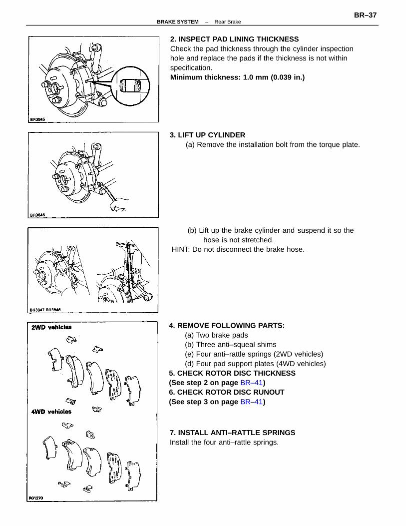
4. REMOVE FOLLOWING PARTS:(a) Two brake pads(b) Three anti–squeal shims(e) Four anti–rattle springs (2WD vehicles)(d) Four pad support plates (4WD vehicles)
5. CHECK ROTOR DISC THICKNESS(See step 2 on page BR–41)6. CHECK ROTOR DISC RUNOUT(See step 3 on page BR–41)
2. INSPECT PAD LINING THICKNESSCheck the pad thickness through the cylinder inspectionhole and replace the pads if the thickness is not withinspecification.Minimum thickness: 1.0 mm (0.039 in.)
(b) Lift up the brake cylinder and suspend it so thehose is not stretched.
HINT: Do not disconnect the brake hose.
3. LIFT UP CYLINDER(a) Remove the installation bolt from the torque plate.
7. INSTALL ANTI–RATTLE SPRINGSInstall the four anti–rattle springs.
–BRAKE SYSTEM Rear BrakeBR–37

9. INSTALL CYLINDER(a) Draw out a small amount of brake fluid from the
reservoir tank.(b) Press in the piston with a hammer handle or an
equivalent.HINT: If the piston is heavy and difficult to push in,loosen the bleeder plug and push in the piston whileletting some brake fluid escape.
(c) Install the brake cylinder.
8. (4WD vehicles)INSTALL PAD SUPPORT PLATES
Install four pad support plates.9. INSTALL NEW PADS
(a) Apply disc brake grease to both sides of the inneranti–squeal shim.
(b) Install the two anti–squeal shims to the outside pad.(c) Install the anti–squeal shim to the inside pad.
(d) Install and torque the installation bolt.Torque: 20 N–m (200 kgf–cm, 14 ft–lbf)
10. INSTALL REAR WHEEL11 . FILL BRAKE FLUID
(d) Install the two pads with the pad wear indicatorplates facing downward.
NOTICE: There should be no oil or grease adheringto the friction surfaces of the pads or the rotor disc.
7. (2WD vehicles)INSTALL ANTI–RATTLE SPRINGS
Install the four anti–rattle springs.
–BRAKE SYSTEM Rear BrakeBR–38

REMOVAL OF CYLINDER(See page BR–36)1. DISCONNECT FLEXIBLE HOSE
(a) Remove the union bolt and two gaskets from thebrake cylinder, then disconnect the flexible hosefrom the brake cylinder.
(b) Use a container to catch the brake fluid as it drainsout.
2. REMOVE CYLINDER FROM TORQUE PLATERemove the installation bolt and cylinder.
3. REMOVE PADS(See page BR–37)
–BRAKE SYSTEM Rear BrakeBR–39

4. REMOVE PISTON FROM CYLINDER(a) Put a piece of cloth or an equivalent between the
piston and cylinder.(b) Use compressed air to remove the piston from the
cylinder.CAUTION: Do not place your fingers in front of thepiston when using compressed air.
3. REMOVE CYLINDER BOOT SET RING AND CYLINDERBOOT
Using a screwdriver, remove the cylinder boot set ringand cylinder boot.
DISASSEMBLY OF CYLINDER(See page BR–36)1. REMOVE SLIDING BUSHING AND DUST BOOT
5. REMOVE PISTON SEAL FROM BRAKE CYLINDERUsing a screwdriver, remove the piston seal.
2. REMOVE MAIN PIN BOOTPull out the main pin boot.
–BRAKE SYSTEM Rear BrakeBR–40

INSPECTION AND REPAIR OF REARBRAKE COMPONENTS1. MEASURE PAD LINING THICKNESSStandard thickness: 10.0 mm (0.394 in.)Minimum thickness: 1.0 mm (0.039 in.)Replace the pad if the thickness is less than the minimumor if it shows sign of uneven wear.
3. MEASURE ROTOR DISC RUNOUTMeasure the rotor disc runout at 10 mm (0.39 in.) fromthe outer edge of the rotor disc.Maximum disc runout: 0.15 mm (0.0059 in.)If the runout is greater than the maximum, replace thedisc.HINT: Before measuring the runout, confirm that thehub bearing play is within specification.
4. IF NECESSARY, REPLACE ROTOR DISC(a) Remove the axle carrier mounting bolt and nut of
upper side.(b) Remove the torque plate.(c) Remove the hub nuts of the temporarily installed
disc and pull off the rotor disc.(d) Install a new rotor disc and loosely install the hub
nuts.
(e) Install the torque plate and tighten the mountingbolt.
Torque: 47 N–m (475 kgf–cm, 34 ft–lbf)(f) Install the axle carrier mounting bolt and nut of up-
per side.Torque: 226 N–m (2,300 kgf–cm, 166 ft–lbf)
2. MEASURE ROTOR DISC THICKNESSStandard thickness: 10.0 mm (0.394 in.)Minimum thickness: 9.0 mm (0.354 in.)If the disc is scored or worn, or if thickness is less thanminimum, repair or replace the disc.
–BRAKE SYSTEM Rear BrakeBR–41

ASSEMBLY OF CYLINDER(See page BR–36)1. APPLY LITHIUM SOAP BASE GLYCOL GREASE TO
FOLLOWING PARTS:(a) Main pin boot(b) Sliding bushing and dust boot(c) Piston, piston seal and cylinder boot
5. INSTALL SLIDING BUSHING AND DUST BOOTInstall the sliding bushing and dust boot into the brakecylinder.
3. INSTALL CYLINDER BOOT AND SET RING INCYLINDER
4. INSTALL MAIN PIN BOOTInstall the main pin boot in place.
2. INSTALL PISTON SEAL AND PISTON IN CYLINDER
–BRAKE SYSTEM Rear BrakeBR–42

INSTALLATION OF CYLINDER(See page BR–36)1. INSTALL PADS2. INSTALL CYLINDER
(a) Install the brake cylinder:(b) Install and torque the installation bolt.Torque: 20 N–m (200 kgf–cm, 14 ft–lbf)
3. INSTALL FLEXIBLE HOSE TO BRAKE CYLINDERInstall the flexible hose on the brake cylinder with twonew gaskets.Torque: 30 N–m (310 kgf–cm, 22 ft–Ibf)HINT: Insert the flexible hose lock securely in the lockhole in the brake cylinder.
4. FILL BRAKE RESERVOIR WITH BRAKE FLUID ANDBLEED BRAKE SYSTEM
(See page BR–7)5. CHECK FOR LEAKS
–BRAKE SYSTEM Rear BrakeBR–43

DISASSEMBLY OF PARKING BRAKE1. REMOVE REAR DISC BRAKE ASSEMBLY
(a) Remove the axle carrier mounting bolt and nut ofupper side.
(b) Remove the two mounting bolts and remove thedisc brake assembly.
(c) Suspend the disc brake so the hose is not stretched.
2. REMOVE ROTOR DISCHINT: If the rotor disc cannot be removed easily, returnthe shoe adjuster until the wheel turns freely.
Parking Brake(For Rear Disc Brake)COMPONENTS
–BRAKE SYSTEM Rear BrakeBR–44

5. REMOVE REAR SHOE(a) Slide out the rear shoe.(b) Remove the tension spring from the rear shoe.(c) Disconnect the parking brake cable from the parking
brake shoe lever.(d) Remove the shoe hold–down spring cups, springs
and pins.
4. REMOVE FRONT SHOE, ADJUSTER AND TENSIONSPRING(a) Slide out the front shoe–and remove the shoe adjust-
er.(b) Remove the shoe strut with spring.(c) Disconnect the tension spring and remove the front
shoe.
3. REMOVE SHOE RETURN SPRINGSUsing needle–nose pliers, remove the shoe return springs.
–BRAKE SYSTEM Rear BrakeBR–45

5. MEASURE CLEARANCE BETWEEN PARKING BRAKESHOE AND LEVER
Using a feeler gauge, measure the clearance.Standard clearance: Less than 0.35 mm
(0.0138 in.)If the clearance is not within specification, replace theshim with one of the correct size.
2. MEASURE BRAKE SHOE LINING THICKNESSStandard thickness: 2.0 mm (0.079 in.)Minimum thickness: 1.0 mm (0.039 in.)If the shoe lining is less than minimum or shows signs ofuneven wear, replace the parking brake shoes.
3. MEASURE BRAKE DISC INSIDE DIAMETERStandard inside diameter: 170 mm (6.69 in.)Maximum inside diameter: 171 mm (6.73 in.)If the disc is scored or worn, the brake disc may be lathedto the maximum inside diameter.
4. INSPECT PARKING BRAKE LINING AND DISC FORPROPER CONTACT
If the contact between the brake lining and disc is improper,repair the lining with a brake shoe grinder, orreplace the brake shoe assembly.
INSPECTION AND REPAIR OF PARKINGBRAKE COMPONENTS1. INSPECT DISASSEMBLED PARTSInspect the disassembled parts for wear, rust or damage.
–BRAKE SYSTEM Rear BrakeBR–46

6. IF NECESSARY, REPLACE SHIM(a) Remove the parking brake lever, and install the correct
size shim.
(b) Install the parking brake lever with a new C–washer.
(c) Remeasure the clearance.
–BRAKE SYSTEM Rear BrakeBR–47

ASSEMBLY OF PARKING BRAKE(See page BR–44)HINT: Assemble the parts in the correct direction asshown.
3. CONNECT PARKING BRAKE CABLE TO PARKINGBRAKE LEVER(a) Install the shoe hold–down springs, cups and pins.(b) Connect the parking brake cable to the parking
brake lever of the rear shoe.
1. APPLY HIGH TEMPERATURE GREASE ON BACKINGPLATE AS SHOWN
Apply high temperature grease to the sliding surfaces ofthe shoe.
2. APPLY HIGH TEMPERATURE GREASE TO ADJUSTERAS SHOWN
–BRAKE SYSTEM Rear BrakeBR–48

5. INSTALL TENSION SPRING, FRONT SHOE ANDADJUSTER(a) Install the tension spring to the rear shoe.(b) Install the front shoe to the tension spring.(c) Install the adjuster between the front and rear shoes.(d) Install the shoe strut with spring.
4. INSTALL REAR SHOESlide in the rear shoe between the shoe hold–downspring cup and the backing plate.CAUTION: Do not allow oil or grease to get on therubbing face.
7. INSTALL ROTOR DISC(a) Before installing, polish the disc and shoe surfaces
with sandpaper.(b) Align the hole on the rear axle shaft flange and
service hole on the disc.
6. INSTALL SHOE RETURN SPRINGSUsing needle–nose pliers, install the shoe return springs.
(e) Slide in the front shoe between the shoe hold–down spring cup and the backing plate.
–BRAKE SYSTEM Rear BrakeBR–49

10. INSTALL REAR WHEEL11. SETTLING PARKING BRAKE SHOES AND DISC
(a) Drive the vehicle at about 50 km/h (31 mph) on asafe, level and dry road.
(b) With the parking brake release button pushed in,pull on the lever with 88 N (9 kgf, 19.8 lbf) of force.
(c) Drive the vehicle for about 400 meters (0.25 mile) inthis condition.
(d) Repeat this procedure two or three times.12. RECHECK AND ADJUST PARKING BRAKE LEVER
TRAVEL
8. ADJUST PARKING BRAKE SHOE CLEARANCE(a) Temporarily install the hub nuts.(b) Remove the hole plug.(c) Turn the adjuster and expand the shoes until the
rotor disc locks.(d) Return the adjuster eight notches.(e) Install the hole plug.
9. INSTALL REAR DISC BRAKE ASSEMBLY(a) Install the disc brake assembly and torque the two
mounting bolts.Torque: 47 N–m (475 kgf–cm, 34 ft–lbf)
(b) Install the axle carrier bolt and nut of upper side.Torque: 226 N–m (2,300 kgf–cm, 166 ft–lbf)
–BRAKE SYSTEM Rear BrakeBR–50

If the rear wheel cylinder pressure is incorrect, replace theP valve assembly.4. BLEED BRAKE SYSTEM5. CHECK FLUID LEAKAGE
PROPORTIONING VALVE (P VALVE)CHECK OF FLUID PRESSURE1. CONNECT FLUID PRESSURE GAUGE TO P VALVE
2. BLEED AIR FROM FLUID PRESSURE GAUGE3. RAISE MASTER CYLINDER PRESSURE AND CHECK
REAR WHEEL CYLINDER PRESSURE
Rear Wheel cylinder pressureMaster cylinder pressure
CoupeandLiftback
Specifications
Con–vertible
4A–FE
5S–FE
4WD
2WD
–BRAKE SYSTEM P ValveBR–51

ANTI–LOCK BRAKE SYSTEM (ABS)Description• The ABS is a brake system which controls the wheel cylinder hydraulic pressure of all four wheels during
sudden braking and braking on slippery road surfaces, preventing the wheels from locking. This ABSprovides the following benefits:
(1) Enables steering round an obstacle with a greater degree of certainly even when panic braking.(2) Enables stopping in a panic brake while keeping effect upon stability and steerability to a minimum,even on curves.
• The function of the ABS is to help maintain directional stability and vehicle steerability on most roadconditions. However, the system cannot prevent the vehicle from skidding if the cornering speed limitis exceeded.
• The ABS has a longitudinal deceleration sensor to match braking characteristics to the full–timefour–wheel drive. (For 4WD)
• In case a malfunction occurs, a diagnosis function and fail–safe system have been adopted for the ABSto increase serviceability.
From the wheel speed signals from each sensor, it calculates acceleration,deceleration and slip values and sends signals to the actuator to controlbrake fluid pressure.
Controls the brake fluid pressure to each disc brake cylinder through signalsfrom the ECU.
Detects the deceleration speed of the vehicle and sends a signal accordinglyto the ABS ECU.
Lights up to alert the driver when trouble has occurred in the AntilockBrake System.
Detects the wheel speed of each of the left and right front wheels.
Detects the wheel speed of each of the left and right rear wheels.
FUNCTION OF COMPONENTS
Deceleration Sensor (For 4WD)
ABS Warning Lamp
Front Speed Sensor
Rear Speed Sensor
Component Function
ABS ECU
Actuator
–BRAKE SYSTEM Anti–Lock Brake System (ABS)BR–52

LOCATION OF SYSTEM PARTS
–BRAKE SYSTEM Anti–Lock Brake System (ABS)BR–53
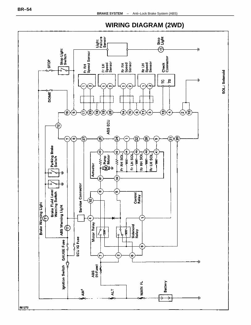
WIRING DIAGRAM (2WD)
–BRAKE SYSTEM Anti–Lock Brake System (ABS)BR–54

CONNECTORS (2WD)
–BRAKE SYSTEM Anti–Lock Brake System (ABS)BR–55

WIRING DIAGRAM (4WD)
–BRAKE SYSTEM Anti–Lock Brake System (ABS)BR–56

CONNECTORS (4WD)
–BRAKE SYSTEM Anti–Lock Brake System (ABS)BR–57

Diagnosis SystemDESCRIPTIONIf a malfunction occurs, the system will identify the problemand the ECU will stores the codes for the troubleitems.At the same time, the system informs the driver of amalfunction via the ”ABS” warning light in the combinationmeter.To identify the trouble by the number of blinks (diagnosticcode) of the warning light turn on the ignition switch,disconnect the service connector, and use SST to connectTc and E1 of the check connector.In the event of two codes, that having the smallest number(code) will be identified first.HINT: The warning light does not show the diagnosticcodes while the vehicle is running.
INITIAL CHECKCHECK ACTUATOR OPERATION NOISE
(a) Start the engine and drive at a speed over 6 km/h (4mph).
(b) Check that the actuator operation noise is heard.HINT: A initial check is carried out once each time afterthe engine has been started and initial speed exceeds 6km/h (4 mph). The respective functions, in order, of the3 position solenoid and pump motor in the actuator arechecked. However, if the brake pedal is depressed, theinitial check is not carried out, but is started after thepedal has been released.
INSPECTION OF DIAGNOSIS SYSTEM1. INSPECT BATTERY VOLTAGEInspect that the battery voltage is about 12 V.2. CHECK THAT WARNING LIGHT TURNS ON
(a) Turn the ignition switch on.(b) Check that the ”ABS” warning light turns on for 3
seconds.If not, inspect and repair or replace the fuse, bulb andwire harness.
–BRAKE SYSTEM Anti–Lock Brake System (ABS)BR–58

(d) In event of a malfunction, 4 seconds later thewarning light will begin to blink. Read the num-ber of blinks.(See DIAGNOSTIC CODE on page BR–60)
HINT: The first number of blinks will equal the first digitof a two digit diagnostic code. After a 1.5 second pause,the 2nd number of blinks will equal the 2nd number of atwo digit code. If there are two or more codes, there willbe a 2.5 second pause between each, and indicationwill begin after 4.0 second pause from the smaller valueand continue in order to larger.
(e) If the system is operating normally (no malfunc-tion), the warning light will blink once every 0.5seconds.
(f) Repair the system.(g) After the malfunctioning components has been re-
paired, clear the diagnostic codes stored in theECU.(See page BR–61)
HINT: If you disconnect the battery cable while repair-ing, all diagnostic codes in the ECU will erased.
(h) Remove the SST from terminals Te and E1 of thecheck connector.
SST 09843–18020(i) Connect the service connector.(j) Turn the ignition switch on, and check that the
”ABS” warning light goes off after the warninglight goes on for 3 seconds.
(c) Using SST, connect terminals Te and E1 of thecheck connector.
SST 09843–18020
3. READ DIAGNOSTIC CODE(a) Turn the ignition switch on.(b) Disconnect the service connector.
–BRAKE SYSTEM Anti–Lock Brake System (ABS)BR–59

• Speed sensor• Sensor rotor• Wire harness and connector
of speed sensor
• Actuator inside wire harness• Control relay• Wire harness and connector of
control relay circuit
• Actuator inside wire harness• Control relay• Wire harness and connector of
control relay circuit
• Deceleration sensor• Deceleration sensor installation• Wire harness and connector of
deceleration sensor
• Pump motor, relay and battery• Wire harness, connector and
ground bolt or actuator pump motorcircuit
Pump motor of actuator locked or open circuit inpump motor circuit in actuator
• Actuator solenoid• Wire harness and connector of
actuator solenoid circuit
Abnormal battery voltage (9.5 V less thanor 16.2 V more than)
Open or short circuit in 3 position solenoid of front right wheel
Open or short circuit in 3 position solenoid of rear right wheel
Open or short circuit in 3 position solenoid of front left wheel
Open or short circuit in 3 position solenoid of rear left wheel
Open circuit in front left or rear right wheel speed sensor
Open circuit in front right or rear left wheel speed sensor
Front left wheel speed sensor signal malfunction
Front right wheel speed sensor signal malfunction
Rear right wheel speed sensor signal malfunction
Rear left wheel speed sensor signal malfunction
Open or short circuit indeceleration sensor
• Battery• Voltage regulator
Open circuit in control relay circuit
Open circuit in control relay circuit
Short circuit in control relay circuit
Short circuit in control relay circuit
Malfunction in decelerationsensor
*:For2WD *:For4WD
Wrong both rear axle hubs • Rear sensor rotors
Malfunction in ECU
Light PatternTrouble Part
DiagnosisCode No.
• ECU
B R
4154
–B
RA
KE
SY
ST
EM
Anti–Lock B
rake System
(AB
S)
BR
–60

CLEARING OF DIAGNOSTIC CODESCLEAR DIAGNOSTIC CODES
(a) Turn the ignition switch on.(b) Using SST, connect terminals Te and E1 of the
check connector.SST 09843–18020HINT: Keep the vehicle stopped vehicle speed 0 km/h
(0 mph).
(c) Clear the diagnostic codes stored in ECU by de-pressing the brake pedal 8 or more times within3 seconds.
(e) Remove the SST from terminals Tc and E1 of thecheck connector.
SST 09843–18020
(d) Check that the warning light shows the normalcode.
(f) Check that the warning light goes off.
–BRAKE SYSTEM Anti–Lock Brake System (ABS)BR–61

Disconnect service connector and connectterminals Tc and E1 of check connector.(See page BR–59)
Does warning light always come on or showthe normal code? (Ignition switch on)
Skidding noise occurs while ABS working.(ABS works inefficiently)
YESContinued on page BR–63
ABS operates just before stopping at ordinary braking.
Brake pedal pulsates abnormally while ABS is operating.
Does not come on for 3 seconds after ignition switch on.
Always comes on after ignition switch is turned on.
See diagnostic code.(See page BR–60)
Troubleshooting
”ABS” warning light comes on.
ABS operates at ordinary braking.
Comes on while running.
”ABS” warning light
Braking inefficient.
Comes on and off.
Brake working
Brakes pull.
Problem No.
–BRAKE SYSTEM Anti–Lock Brake System (ABS)BR–62

Does warning light go off when both theECU connector and service connectorare disconnected? (Ignition switch on)
Is there 10 – 16 V between terminal IG onECU wire harness side connector andbody ground? (Ignition switch on)
Short circuit in wire harness betweenECU terminal w and control relayterminal W.
Is connector of ECU properly connected?And are all terminals in the connector?
Continued from page BR–62
Faulty power circuit.
Faulty connector.
YES(Goes off)
NO(Come on)
Faulty ECU.
YES
YES
–BRAKE SYSTEM Anti–Lock Brake System (ABS)BR–63
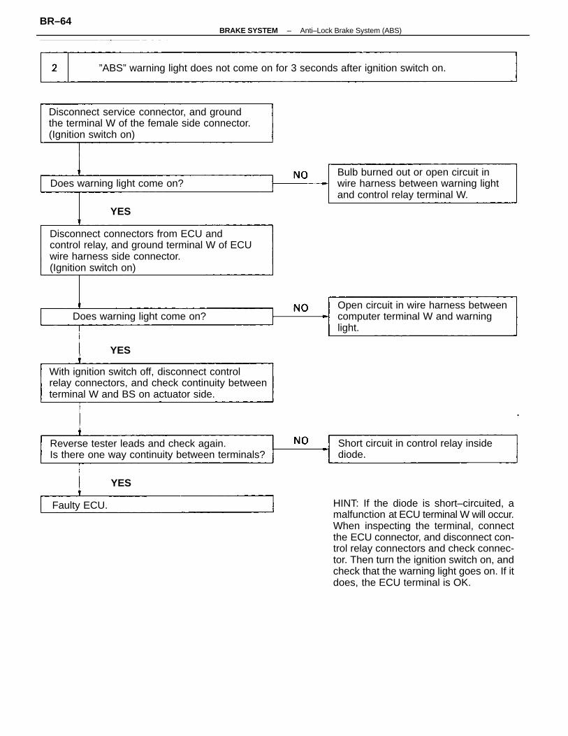
HINT: If the diode is short–circuited, amalfunction at ECU terminal W will occur.When inspecting the terminal, connectthe ECU connector, and disconnect con-trol relay connectors and check connec-tor. Then turn the ignition switch on, andcheck that the warning light goes on. If itdoes, the ECU terminal is OK.
Disconnect connectors from ECU andcontrol relay, and ground terminal W of ECUwire harness side connector.(Ignition switch on)
With ignition switch off, disconnect controlrelay connectors, and check continuity betweenterminal W and BS on actuator side.
Disconnect service connector, and groundthe terminal W of the female side connector.(Ignition switch on)
Open circuit in wire harness betweencomputer terminal W and warninglight.
”ABS” warning light does not come on for 3 seconds after ignition switch on.
Bulb burned out or open circuit inwire harness between warning lightand control relay terminal W.
Reverse tester leads and check again.Is there one way continuity between terminals?
Short circuit in control relay insidediode.
Does warning light come on?
Does warning light come on?
Faulty ECU.
YES
YES
YES
–BRAKE SYSTEM Anti–Lock Brake System (ABS)BR–64

• Brakes pull.• Braking inefficient.• ABS operates at ordinary braking.• ABS operates just before stopping at ordinary braking.• Brake pedal pulsates abnormally while ABS working.
(For 4WD)Try deceleration sensor operation diagnosissystem. Is sensor operation OK?(See page BR–84)
Disconnect connector from ECU, inspectcontinuity between each speed sensorterminals on wire harness side.(See page BR–86)
• Check for short circuit in wire harness between terminal Tc and E1 or Ts and E1 of check connector.
Disconnect service connector and connectterminals Tc and E1of check connector.(See page BR–59)
Are each speed sensors installed in place?And are each installation bolts tightenedsecurely?
Try speed sensor diagnosis system.Is sensor signal change OK?(See page BR–68)
Does warning light show the diagnostic normalcode? (Ignition switch on)
Is there foreign material or ferric chips on thesensor tip?
Faulty deceleration sensor or sensorinstallation faulty.
Inspect sensor rotor, and replace ifnecessary.
”ABS” warning light comes on and off.
Clean chips from the speed sensor.
See diagnostic code.(See page BR–60)
Speed sensor installation faulty.
Continued on page BR–66
YES
YES
YES
YES
YES
–BRAKE SYSTEM Anti–Lock Brake System (ABS)BR–65

Does any abnormal change occur in continuitywhen the connectors or wire harness of thespeed sensor and intermediate connectors aretwisted or bent?
Inspect the actuator operation.(See page BR–76)
YES
Continued from page BR–65
Is actuator operation OK?
NO
(No change)
Faulty wire harness.
Faulty actuator.
Faulty ECU.
YES
(Abnormalchange)
–BRAKE SYSTEM Anti–Lock Brake System (ABS)BR–66

Is there battery voltage between ECUterminal STP and body ground when depressingbrake pedal?
Disconnect service connector and connectterminals Te and E1 of check connector.(See page BR–59)
Does warning light show the diagnostic normalcode? (Ignition switch on)
Open circuit in stop light switch and/or wire harness.
Antilock brake system works inefficiently.
See diagnostic code.(See page BR–60)
Inspect actuator.(See page BR–76)
YES
YES
–BRAKE SYSTEM Anti–Lock Brake System (ABS)BR–67

Speed Sensor and DecelerationSensor Diagnosis SystemPRECAUTION
While checking the speed sensor and deceleration sen-sor diagnosis system, ABS does not work and brakesystem works as normal brake system.
INSPECTION OF DIAGNOSIS SYSTEM1. INSPECT BATTERY VOLTAGE
Inspect that the battery voltage is about 12 V.2. CHECK THAT WARNING LIGHT TURNS ON
(a) Turn the ignition switch on.(b) Check that the ”ABS” warning light turns on for 3
seconds.If not, inspect and repair or replace the fuse, bulb andwire harness.(c) Check that the ”ABS” warning light turns off.(d) Turn the ignition switch off.
3. PERFORM FOLLOWING STEPS(a) Using SST, connect terminals Ts to E1 of the check
connector.SST 09843–18020(b) Pull the parking brake lever up, and start the engine.HINT: Do not depress the brake pedal.
(c) Check that the warning light blinks about 4 timesevery 1 second as shown.
–BRAKE SYSTEM Anti–Lock Brake System (ABS)BR–68
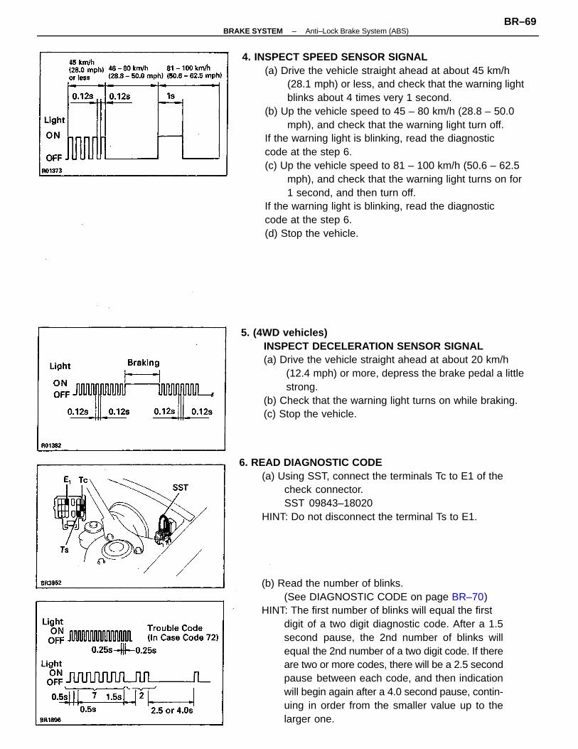
4. INSPECT SPEED SENSOR SIGNAL(a) Drive the vehicle straight ahead at about 45 km/h
(28.1 mph) or less, and check that the warning lightblinks about 4 times very 1 second.
(b) Up the vehicle speed to 45 – 80 km/h (28.8 – 50.0mph), and check that the warning light turn off.
If the warning light is blinking, read the diagnosticcode at the step 6.(c) Up the vehicle speed to 81 – 100 km/h (50.6 – 62.5
mph), and check that the warning light turns on for1 second, and then turn off.
If the warning light is blinking, read the diagnosticcode at the step 6.(d) Stop the vehicle.
(b) Read the number of blinks.(See DIAGNOSTIC CODE on page BR–70)
HINT: The first number of blinks will equal the firstdigit of a two digit diagnostic code. After a 1.5second pause, the 2nd number of blinks willequal the 2nd number of a two digit code. If thereare two or more codes, there will be a 2.5 secondpause between each code, and then indicationwill begin again after a 4.0 second pause, contin-uing in order from the smaller value up to thelarger one.
5. (4WD vehicles)INSPECT DECELERATION SENSOR SIGNAL(a) Drive the vehicle straight ahead at about 20 km/h
(12.4 mph) or more, depress the brake pedal a littlestrong.
(b) Check that the warning light turns on while braking.(c) Stop the vehicle.
6. READ DIAGNOSTIC CODE(a) Using SST, connect the terminals Tc to E1 of the
check connector.SST 09843–18020
HINT: Do not disconnect the terminal Ts to E1.
–BRAKE SYSTEM Anti–Lock Brake System (ABS)BR–69

DIAGNOSTIC CODE
All speed sensors and sensor rotors are normal
Abnormal change of front right speedsensor signal
Abnormal change of rear right speedsensor signal
Abnormal change of front left speedsensor signal
Abnormal change of rear left speedsensor signal
• Front right speed sensor• Sensor installation
• Rear right speed sensor• Sensor installation
• Front left speed sensor• Sensor installation
• Rear left speed sensor• Sensor installation
Low voltage of front left speed sensor signal
Low voltage of front right speed sensor signal
Low voltage of rear right speed sensor signal
Low voltage of rear left speed sensor signal
• Front right sensor rotor
• Rear right sensor rotor
• Front left sensor rotor
• Rear left sensor rotor
Malfunctioning PartLight Pattern DiagnosisCode No.
74
75
73
76
72
78
77
–B
RA
KE
SY
ST
EM
Anti–Lock B
rake System
(AB
S)
BR
–70

INSPECTION OF DECELERATIONSENSOR INSTALLATION1. INSPECT BATTERY VOLTAGE
Inspect that the battery voltage is about 12 V.2. INSPECT SENSOR DETECTION POINT
(a) Turn the ignition switch off.(b) Using SST, connect terminals Ts and E1 of the
check connector.SST 09843–18020(c) Pull the parking brake lever up and depress the
brake pedal, and turn the ignition switch on.(d) Check that the warning light blinks about 4 times
every 1 second as shown.
(h) Jack up the front side of the vehicle slowly asshown.
HINT: When measuring the height, measure at thecenter of the lower body or spoiler edge of the vehicle.
(i) Check that the warning light does not turn on.(j) Jack down the vehicle and check that the warning light
blinking.If the warning light turns on, inspect the deceleration sensorinstallation. And if the sensor installation is OK, replace thedeceleration sensor.
7. REPAIR MALFUNCTIONING PARTSRepair or replace the malfunctioning parts.
8. PERFORM FOLLOWING STEPS(a) Turn the ignition switch off.(b) Remove the SST from terminals E1 and Tc, Ts of
the check connector.
(e) Jack up the rear side of the vehicle slowly asshown.
HINT: When measuring the height, measure at thecenter of the rear bumper lower edge.
(f) Check that the warning light does not turn on.(g) Jack down the vehicle and check that the warning
light blinking.
–BRAKE SYSTEM Anti–Lock Brake System (ABS)BR–71

(k) Turn the ignition switch off.(l) Remove the SST from terminal Ts and E1 of the
check connector.
–BRAKE SYSTEM Anti–Lock Brake System (ABS)BR–72

1. DISCONNECT AND CONNECT BRAKE TUBEUsing SST, disconnect and connect the brake tubes
from/to the ABS actuator.SST 09751–36011Torque: 15 N–m (155 kgf–cm, 11 ft–Ibf)
2. FILL BRAKE RESERVOIR WITH BRAKE FLUID ANDBLEED BRAKE SYSTEM(See page BR–7)
ABS ActuatorREMOVAL AND INSTALLATION OF ABSACTUATORRemove and install the parts as shown.
–BRAKE SYSTEM Anti–Lock Brake System (ABS)BR–73

2. INSTALL ACTUATOR(a) Install the actuator to the actuator bracket in place.(b) Install the washers, wave washers and nuts.(c) Tighten the three nuts.Torque: 5.4 N–m (55 kgf–cm, 48 in.–lbf)HINT: Before installing the front right side nut, installthe motor ground terminal between the plate washer andspring washer.
(MAIN POINT OF REMOVAL ANDINSTALLATION)1. DISCONNECT AND CONNECT BRAKE TUBE
Using SST, disconnect and connect the brake tubesfrom/to the ABS actuator.
SST 09751–36011Torque: 15 N–m (155 kgf–cm, 11 ft–lbf)
DISASSEMBLY AND ASSEMBLY OFABS ACTUATOR
Remove and install the parts as shown.
COMPONENTS
–BRAKE SYSTEM Anti–Lock Brake System (ABS)BR–74
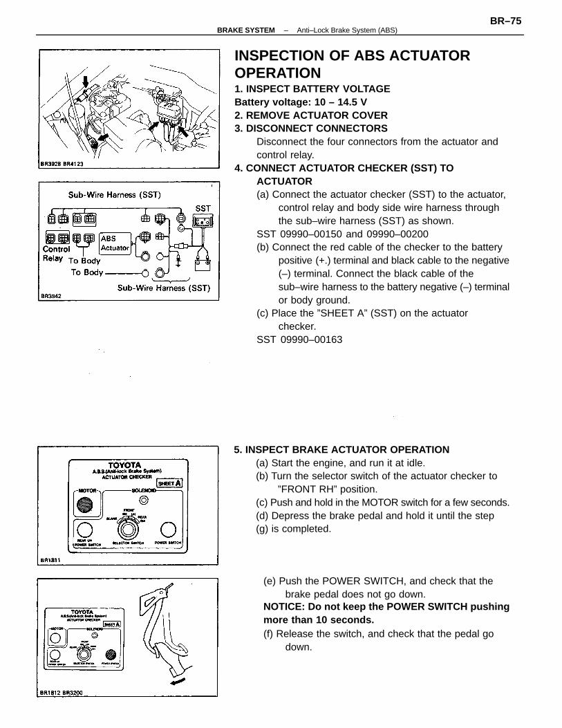
INSPECTION OF ABS ACTUATOROPERATION1. INSPECT BATTERY VOLTAGEBattery voltage: 10 – 14.5 V2. REMOVE ACTUATOR COVER3. DISCONNECT CONNECTORS
Disconnect the four connectors from the actuator andcontrol relay.
4. CONNECT ACTUATOR CHECKER (SST) TOACTUATOR(a) Connect the actuator checker (SST) to the actuator,
control relay and body side wire harness throughthe sub–wire harness (SST) as shown.
SST 09990–00150 and 09990–00200(b) Connect the red cable of the checker to the battery
positive (+.) terminal and black cable to the negative(–) terminal. Connect the black cable of thesub–wire harness to the battery negative (–) terminalor body ground.
(c) Place the ”SHEET A” (SST) on the actuatorchecker.
SST 09990–00163
5. INSPECT BRAKE ACTUATOR OPERATION(a) Start the engine, and run it at idle.(b) Turn the selector switch of the actuator checker to
”FRONT RH” position.(c) Push and hold in the MOTOR switch for a few seconds.(d) Depress the brake pedal and hold it until the step(g) is completed.
(e) Push the POWER SWITCH, and check that thebrake pedal does not go down.
NOTICE: Do not keep the POWER SWITCH pushingmore than 10 seconds.(f) Release the switch, and check that the pedal go
down.
–BRAKE SYSTEM Anti–Lock Brake System (ABS)BR–75

9. CONNECT ACTUATOR CONNECTORSConnect the four connectors to actuator and control relay.
10. INSTALL CONNECTORInstall the connector to the actuator bracket.
11. INSTALL ACTUATOR COVER12. CLEAR DIAGNOSTIC CODES
(See page BR–61)
6. INSPECT FOR OTHER WHEELS(a) Turn the selector switch to ”FRONT LH” position.(b) Repeating (c) to (j) of the step 5, check the actuator
operation similarly.(c) Similarly, inspect ”REAR RH” and ”REAR LH” position.HINT: When inspecting ”REAR LH” position, push theREAR LH switch instead of the POWER SWITCH, andyou can inspect in any selector switch position.
7. PUSH MOTOR SWITCHPush and hold in the MOTOR switch for a few seconds.
8. DISCONNECT ACTUATOR CHECKER (SST) FROMACTUATORRemove the ”SHEET A” (SST) and disconnect the actu–tor checker (SST) and sub–wire harness (SST) from theactuator, control relay and body side wire harness.SST 09990–00150, 09990–00200 and 09990–00163
(i) Push and hold in the MOTOR switch for a few sec-onds.
(j) Depress the brake pedal and hold it for about 15seconds. As you hold the pedal down, push theMOTOR switch for a few seconds. Check thatthe brake pedal does not pulsate.
(g) Push and hold in the MOTOR switch for a fewseconds, and check that the pedal returns.
(h) Release the brake pedal.
–BRAKE SYSTEM Anti–Lock Brake System (ABS)BR–76

Control RelayINSPECTION OF CONTROL RELAYINSPECT CONTROL RELAY OPERATION
Inspect the relay continuity between terminals.
If operation is not as specified, replace the relay.
Apply battery voltagebetween terminals 9and 10.
Apply battery voltagebetween terminals 1and 9.
Constant
Terminal
Condition
–BRAKE SYSTEM Anti–Lock Brake System (ABS)BR–77

INSPECTION OF FRONT SPEED SENSOR1. INSPECT SPEED SENSOR
(a) Remove the bolt from the pipe clamp of the wireharness.
(b) Disconnect the speed sensor connector.(c) Measure the resistance between terminals.Resistance: 0.8 –1.3 k �
If resistance value is not as specified, replace the sensor.
2. INSPECT SENSOR INSTALLATION(a) Check that the sensor installation bolt is tighten
properly. If not, tighten the bolt.Torque: 7.8 N–m (80 kgf–cm, 69 in–lbf).(b) Check that there is no clearance between the sensor
and rear axle carrier as shown.If there is clearance, replace the sensor.
(d) Check that there is no continuity between eachterminal and sensor body.
If there is continuity, replace the sensor.(e) Connect the speed sensor connector.(f) Install the bolt of the pipe clamp.
Front Speed Sensor
–BRAKE SYSTEM Anti–Lock Brake System (ABS)BR–78

INSPECTION OF FRONT SPEED SENSORAND SENSOR ROTOR SERRATIONS(REFERENCE)INSPECT FRONT SPEED SENSOR AND SENSOR ROTORSERRATIONS BY USING AN OSCILLOSCOPE
(a) Connect an oscilloscope to the speed sensor connector.(b) Run the vehicle at 20 km/h (12.4 mph), and inspect
speed sensor output wave.(c) Check that C is 0.5 V or more.
If not as specified, replace the speed sensor.(d) Check that B is 70% or more of A.
If not as specified, replace the drive shaft.
3. VISUALLY INSPECT SENSOR ROTOR SERRATIONS(a) Remove the drive shaft.
(See page SA–17 or 33)(b) Inspect the sensor rotor serrations for scratches,
cracks, warping or missing teeth.(c) Install the drive shaft.
(See page SA–30 or 44)NOTICE: To prevent damage to the serrations, do notstrike the drive shaft.
–BRAKE SYSTEM Anti–Lock Brake System (ABS)BR–79

INSPECTION OF REAR SPEED SENSOR1. INSPECT SPEED SENSOR
(a) Remove the seat cushion.(b) Disconnect the speed sensor connector.(c) Measure the resistance between terminals.
Resistance: 1.1 –1.7 K �
If resistance value is not as specified, replace the sensor.
2. INSPECT SENSOR INSTALLATION(a) Check that the sensor installation bolt is tightened
properly. If not, tighten the bolt.Torque: 7.8 N–m (80 kgf–cm, 69 in.–lbf)(b) Check that there is no clearance between the sensor
and rear axle carrier as shown.If there is clearance, replace the sensor.
(d) Check that there is no continuity between eachterminal and sensor body.
If there is continuity, replace the sensor.(e) Connect the speed sensor connector.(f) Install the seat back and seat cushion.
Rear Speed Sensor (2WD)
–BRAKE SYSTEM Anti–Lock Brake System (ABS)BR–80

INSPECTION OF REAR SPEED SENSORAND SENSOR ROTOR SERRATIONS(REFERENCE)INSPECT REAR SPEED SENSOR AND SENSOR ROTORSERRATIONS BY USING AN OSCILLOSCOPE
(a) Connect an oscilloscope to the speed sensor connector.(b) Run the vehicle at 20 km/h (12.4 mph), and inspect
speed sensor output wave.(c) Check that C is 0.5 V or more.If not as specified, replace the speed sensor.(d) Check that B is 70% or more of A.If not as specified, replace the rear axle hub.
3. VISUALLY INSPECT SENSOR ROTOR SERRATIONS(a) Remove the axle hub assembly.
(See page SA–59)(b) Inspect the sensor rotor serrations for scratches,
cracks, warping or missing teeth.(c) Install the axle hub assembly.
(See page SA–64)NOTICE: To prevent damage to the serrations, do notstrike the axle hub assembly.
–BRAKE SYSTEM Anti–Lock Brake System (ABS)BR–81

INSPECTION OF REAR SPEED SENSOR1. INSPECT SPEED SENSOR
(a) Remove the seat cushion.(b) Disconnect the speed sensor connector.(c) Measure the resistance between terminals.Resistance: 0.8 –1.5 K �
If resistance value is not as specified, replace the sensor.
2. INSPECT SENSOR INSTALLATION(a) Check that the sensor installation bolt is tightened
properly. If not, tighten the bolt.Torque: 19 N–m (195 kgf–cm, 14 ft–lbf)(b) Check that there is no clearance between the sensor
and rear axle carrier as shown.If there is clearance, replace the sensor.
(d) Check that there is no continuity between eachterminal and sensor body.
If there is continuity, replace the sensor.(e) Connect the speed sensor connector.(f) Install the seat back and seat cushion.
Rear– Speed Sensor (4WD)
–BRAKE SYSTEM Anti–Lock Brake System (ABS)BR–82

INSPECTION OF REAR SPEED SENSORAND SENSOR ROTOR SERRATIONS(REFERENCE)INSPECT REAR SPEED SENSOR AND SENSOR ROTORSERRATIONS BY USING AN OSCILLOSCOPE
(a) Connect an oscilloscope to the speed sensor connector.(b) Run the vehicle at 20 km/h (12.4 mph), and inspect
speed sensor output wave.(c) Check that C is 0.5 V or more.
If not as specified, replace the speed sensor.(d) Check that B is 60% or more of A.
If not as specified, replace the drive shaft.
3. VISUALLY INSPECT SENSOR ROTOR SERRATIONS(a) Remove the drive shaft.
(See page SA–78)(b) Inspect the sensor rotor serrations for scratches,
cracks, warping or missing teeth.(c) Install the drive shaft.
(See page SA–85)NOTICE: To prevent damage to the serrations, do notstrike the drive shaft.
–BRAKE SYSTEM Anti–Lock Brake System (ABS)BR–83

Anti–Lock Brake System CircuitINSPECTION OF SYSTEM CIRCUIT(2WD vehicles)1. INSPECT SYSTEM CIRCUIT WITH CONNECTOR CON–
NECTED(a) Remove the ABS ECU.(b) Using a voltmeter with high impedance (10 K ohm/
V minimum), measure the voltage at each terminaland body ground.
IG switch on and check connector Tc–E1 not connected
IG switch on and check connector Ts–E1 not connected
IG switch on and check connector Ts–E1 not connected
IG switch on and check connector Ts–E1 connected
IG switch on and check connector Tc–E1 connected
IG switch on and ”ABS” warning light goes on
IG switch on and ”ABS” warning light goes off
IG switch on and ”ABS” warning light goes off
IG switch on and ”ABS” warning light goes off
IG switch on and ”ABS” warning light goes on
IG switch on and ”ABS” warning light goes on
IG switch off and brake pedal depressed
IG switch o and brake pedal returned
Parking brake switchLevel warning switchIG switch on and PKB lever returned
Continued on page BR–85
IG switch on and PKB lever pulled
ABS ECU”ABS” warning light
Stop light switchStop light
TesterConnection
Battery voltage
Battery voltage
Battery voltage
Battery voltage
Battery voltage
Battery voltage
Specified Value
Battery voltage
Battery voltage
Battery voltage
Wiring harness
IG switch off
IG switch off
IG switch off
IG switch off
IG switch off
IG switch off
IG switch off
IG switch on ECU–IG Fuse
Trouble PartCheck Item
Continuity
Continuity
Continuity
Continuity
Continuity
Continuity
Continuity
Continuity
Continuity
Continuity
Continuity
Continuity
Continuity
DOME Fuse
Continuity
Condition
About OV
About OV
About OV
About OV
About OV
About OV
About OV
Voltage
Voltage
Voltage
VoltageABS ECU
Voltage
Voltage
Voltage
Voltage
ABS ECU
ABS ECU
ABS ECU
Voltage
Actuator
Actuator
Voltage
GND
STP
PK6
RL–
D/G
SFR
FSS
SRL
RSS
SAT
RR–
IG1
–BRAKE SYSTEM Anti–Lock Brake System (ABS)BR–84
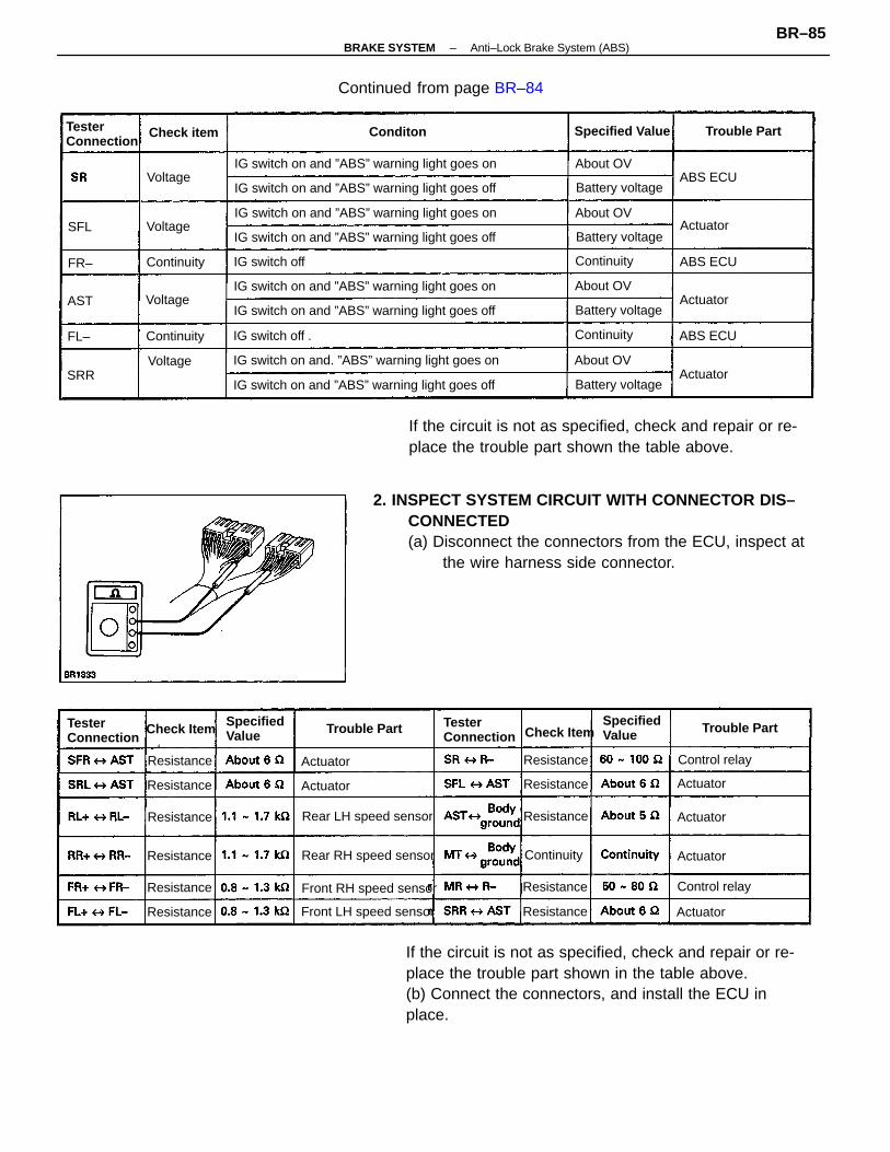
2. INSPECT SYSTEM CIRCUIT WITH CONNECTOR DIS–CONNECTED(a) Disconnect the connectors from the ECU, inspect at
the wire harness side connector.
If the circuit is not as specified, check and repair or re-place the trouble part shown in the table above.(b) Connect the connectors, and install the ECU inplace.
If the circuit is not as specified, check and repair or re-place the trouble part shown the table above.
IG switch on and ”ABS” warning light goes on
IG switch on and ”ABS” warning light goes off
IG switch on and ”ABS” warning light goes off
IG switch on and ”ABS” warning light goes off
IG switch on and. ”ABS” warning light goes on
IG switch on and ”ABS” warning light goes on
IG switch on and ”ABS” warning light goes off
IG switch on and ”ABS” warning light goes on
Continued from page BR–84
Rear RH speed sensor
Rear LH speed sensor
Front LH speed sensor
Front RH speed sensor
TesterConnection
TesterConnection
TesterConnection
Specified Value
Battery voltage
Battery voltage
Battery voltage
Battery voltage
SpecifiedValue
Voltage
SpecifiedValue
Actuator
Resistance
IG switch off .
Control relay
Control relay
IG switch off
Trouble Part
Trouble PartTrouble Part
Check item
Continuity
Continuity
Continuity
Check ItemCheck Item
Continuity
Continuity
Resistance
Resistance
Resistance
Resistance
ResistanceResistance
Resistance
Resistance
Resistance
Resistance
Actuator
About OV
Conditon
About OV
Actuator
About OV
About OV
Actuator
ABS ECUVoltage
Actuator
ABS ECU
ABS ECU
Actuator
Actuator
Actuator
Actuator
Voltage
Voltage
SFL
SRR
AST
FL–
FR–
–BRAKE SYSTEM Anti–Lock Brake System (ABS)BR–85

(4WD vehicles)1. INSPECT SYSTEM CIRCUIT WITH CONNECTOR CON–
NECTED(a) Remove the ABS ECU.(b) Using a voltmeter with high impedance (10 K ohm/
V minimum), measure the voltage at each terminaland body ground.
IG switch on and check connector Ts–E1not connected
IG switch on and check connector Ts–E1not connected
IG switch on and check connector Tc–E1 not connected
IG switch on and check connector Ts–E1connected
IG switch on and check connector Tc–E1 connected
IG switch on and “ABS” warning light goes on
IG switch on and ”ABS” warning light goes off
IG switch on and ”ABS” warning light goes off
IG switch on and ”ABS” warning light goes off
IG switch on and ”ABS” warning light goes on
IG switch on and ”ABS” warning light goes on
IG switch off and brake pedal depressed
IG switch off and brake pedal returned
Parking brake switchLevel warning switch
Continued on page BR–87
IG switch on and PKB lever returned
ABS ECU”ABS” warning light
IG switch on and PKB lever pulled
Stop light switchStop light
Deceleration Sensor
Deceleration Sensor
TesterConnection
Battery voltage
Battery voltage
Battery voltage
Battery voltage
Battery voltage
Specified Value
Battery voltage
Battery voltage
Battery voltage
Wiring harness
IG switch off
IG switch off
IG switch off
IG switch off
IG switch off
IG switch off
Trouble Part
ECU–IG FuseIG switch on
IG switch on
IG switch on
Check item
Continuity
Continuity
Continuity Continuity
Continuity
Continuity
Continuity
Continuity
Continuity
Continuity
Continuity
ContinuityContinuity
Continuity
About OV
About OV
About OV
Condition
About OV
About OV
About OV
About OV
Actuator
ABS ECU
ABS ECU
ABS ECU
ABS ECU
Voltage
ABS ECU
Voltage
Voltage
Voltage
Voltage
Voltage
Voltage
Voltage
Voltage
Voltage
Voltage
4–6V
4–6V
GND
D/G
GS 1
PKB
FSS
GS2
SFR
RSS
RR–
STP
R L–
FR–
–BRAKE SYSTEM Anti–Lock Brake System (ABS)BR–86

2. INSPECT SYSTEM CIRCUIT WITH CONNECTOR DIS–CONNECTED(a) Disconnect the connectors from the ECU, inspect at
the wire harness side connector.
If the circuit is not as specified, check and repair or re-place the trouble part shown in the table above.
(b) Connect the connectors, and install the ECU inplace.
If the circuit is not as specified, check and repair or re-place the trouble part shown in the table above.
IG switch on and ”ABS” warning light goes off
IG switch on and ”ABS” warning light goes off
IG switch on and ”ABS” warning light goes off
IG switch on and ”ABS” warning light goes on
IG switch on and ”ABS” warning light goes off
IG switch on and ”ABS” warning light goes on
IG switch on and ”ABS” warning tight goes on
IG switch on and ”ABS” warning light goes on
Continued from page BR–86
Front LH speed sensor
Rear RH speed sensor
Rear LH speed sensor
Front RH speed sensor
TesterConnection
TesterConnection
TesterConnection
Battery voltage
Battery voltage
Battery voltage
Battery voltage
Specified Value
Battery voltage
SpecifiedValue
SpecifiedValue
Control relay
Control relay
IG switch off
IG switch off
IG switch off
Trouble Part
Trouble Part
Trouble Part
DOME Fuse
Check Item
Check Item
Continuity
Continuity
Check Item
Continuity
Resistance
ContinuityContinuity
Resistance
Resistance
Resistance
ResistanceResistance
ResistanceResistance
Resistance
Resistance
Resistance
Condition
About OV
About OV
About OV
About OV
ABS ECU
Actuator
Actuator
Actuator
Actuator
Actuator
Actuator Actuator
Actuator
Voltage
Voltage
Voltage
Voltage
Voltage
SRL
SFL
AST
SRR
BAT
FL–
–BRAKE SYSTEM Anti–Lock Brake System (ABS)BR–87