bo–1 body - discodan
TRANSCRIPT

BODY–BODY
BO–1

GENERAL INFORMATIONIf there is a possibility that the body and/or parts may bedamaged, first remove the danger before performing repairoperations.Example:1. Apply protection tape to the body adjacent to the body
part when removing and installing.
If anti–rust agents are damaged while repairing other parts,be sure to repair the anti–rust agent.Example:1. If body sealer, paint film or undercoat are damaged by
peeling, cracks, etc., be sure to repair each with an anti-rust agent.
2. When prying off the body parts with a screwdriver orscraper, etc., be sure to apply protection tape to the tip orblade to prevent damage to the paint film or body part.
2. If a hinge or exterior body panel is loosened or removed,be sure to apply rust inhibitor after repairs.
–BODY General InformationBO–2

HOODADJUSTMENT OF HOOD
HINT: Since the centering bolt is used as the hoodhinge and lock set bolt, the hood and lock cannot beadjusted with it on. Substitute the bolt with washer forthe centering bolt.
3. ADJUST REAR EDGE OF HOOD IN VERTICALDIRECTIONAdjust the hood by increasing or decreasing the numberof the washers.
1. ADJUST HOOD IN FORWARD/REARWARD ANDLEFT/RIGHT DIRECTIONSAdjust the hood by loosening the hood side hinge bolts.
2. ADJUST FRONT EDGE OF HOOD IN VERTICALDIRECTIONAdjust the hood by turning the cushions.
4. ADJUST HOOD LOCKAdjust the lock by loosening the bolts.
–BODY HoodBO–3
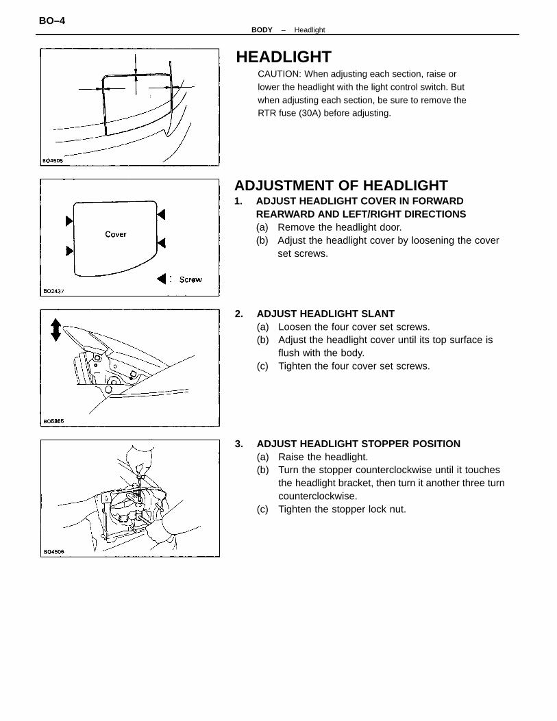
ADJUSTMENT OF HEADLIGHT1. ADJUST HEADLIGHT COVER IN FORWARD
REARWARD AND LEFT/RIGHT DIRECTIONS(a) Remove the headlight door.(b) Adjust the headlight cover by loosening the cover
set screws.
3. ADJUST HEADLIGHT STOPPER POSITION(a) Raise the headlight.(b) Turn the stopper counterclockwise until it touches
the headlight bracket, then turn it another three turncounterclockwise.
(c) Tighten the stopper lock nut.
2. ADJUST HEADLIGHT SLANT(a) Loosen the four cover set screws.(b) Adjust the headlight cover until its top surface is
flush with the body.(c) Tighten the four cover set screws.
HEADLIGHTCAUTION: When adjusting each section, raise orlower the headlight with the light control switch. Butwhen adjusting each section, be sure to remove theRTR fuse (30A) before adjusting.
–BODY HeadlightBO–4
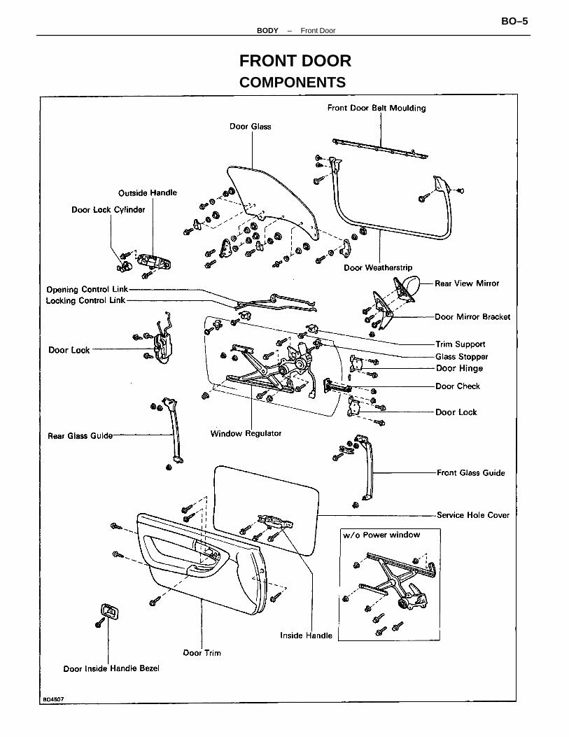
FRONT DOORCOMPONENTS
–BODY Front DoorBO–5

DISASSEMBLY OF FRONT DOOR(See page BO–5)1. (w/o Power Window)
REMOVE REGULATOR HANDLEPull off the snap ring with a shop rag and remove theregulator handle and plate.
ADJUSTMENT OF FRONT DOOR1. ADJUST DOOR IN FORWARD/REARWARD AND
VERTICAL DIRECTIONSUsing SST, adjust the door by loosening the body sidehinge bolts.SST 09812–00010
2. REMOVE DOOR INSIDE HANDLE BEZEL(a) Remove the screw.(b) Using a screwdriver, pry loose the clip and claws of
the bezel to remove it.HINT: Tape the screwdriver tip before use.
3. ADJUST DOOR LOCK STRIKER(a) Check that the door fit and door lock linkages are
adjusted correctly.(b) Loosen the striker mounting screws to adjust.(c) Using a plastic hammer, tap the striker to adjust it.
2. ADJUST DOOR IN LEFT/RIGHT AND VERTICALDIRECTIONSLoosen the door side hinge bolts to adjust.HINT: Substitute the bolt with washer for the centeringbolt. (See page BO–3)
–BODY Front DoorBO–6
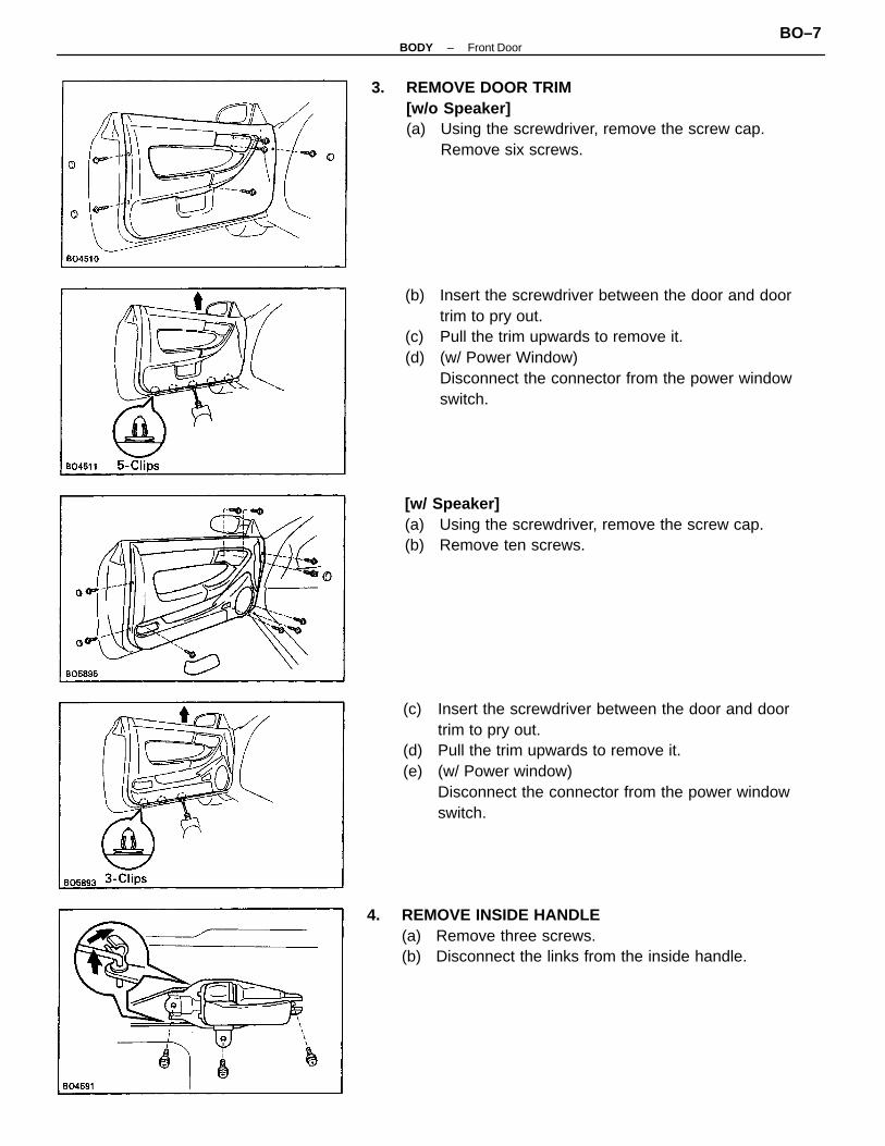
(c) Insert the screwdriver between the door and doortrim to pry out.
(d) Pull the trim upwards to remove it.(e) (w/ Power window)
Disconnect the connector from the power windowswitch.
(b) Insert the screwdriver between the door and doortrim to pry out.
(c) Pull the trim upwards to remove it.(d) (w/ Power Window)
Disconnect the connector from the power windowswitch.
3. REMOVE DOOR TRIM[w/o Speaker](a) Using the screwdriver, remove the screw cap.
Remove six screws.
4. REMOVE INSIDE HANDLE(a) Remove three screws.(b) Disconnect the links from the inside handle.
[w/ Speaker](a) Using the screwdriver, remove the screw cap.(b) Remove ten screws.
–BODY Front DoorBO–7

5. REMOVE REAR VIEW MIRROR[w/o Speaker](a) Remove the cover.(b) (w/ Remote Control Mirror)
Disconnect the connector from the mirror.(c) Remove three screws and the rear view mirror.
[w/ Speaker](a) Remove the cover.(b) (w/ Remote Control Mirror)
Disconnect the connector from the mirror.(c) Remove three screws, speaker and rear view mirror.(d) Disconnect the connector from speaker.
6. REMOVE DOOR MIRROR BRACKET(a) Using a clip remover, remove the clip.(b) Remove two bolts, and the nut.(c) Using a hexagon wrench, remove the stud bolt and
pull out the bracket.
7. REMOVE SERVICE HOLE COVER[w/o Speaker](a) Using a clip remover, remove the screw grommets
and the link guide.(b) Remove service hole cover.
[w/ Speaker](a) Remove three bolts and speaker.(b) Disconnect the connector from speaker.
–BODY Front DoorBO–8
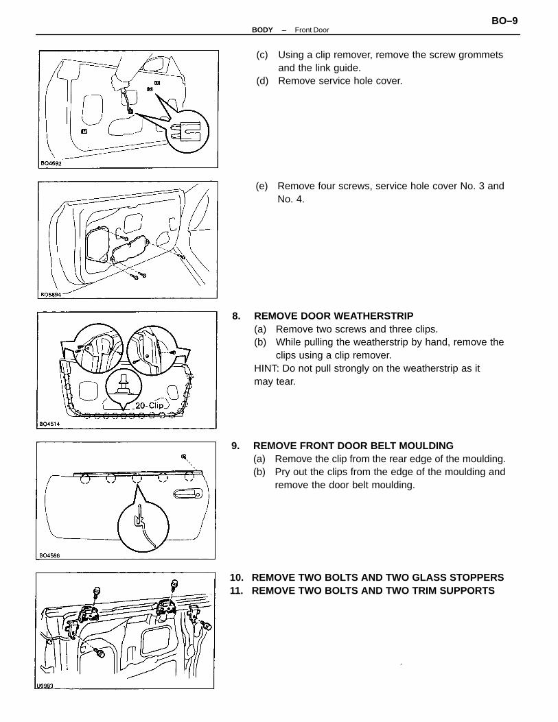
8. REMOVE DOOR WEATHERSTRIP(a) Remove two screws and three clips.(b) While pulling the weatherstrip by hand, remove the
clips using a clip remover.HINT: Do not pull strongly on the weatherstrip as itmay tear.
9. REMOVE FRONT DOOR BELT MOULDING(a) Remove the clip from the rear edge of the moulding.(b) Pry out the clips from the edge of the moulding and
remove the door belt moulding.
(c) Using a clip remover, remove the screw grommetsand the link guide.
(d) Remove service hole cover.
10. REMOVE TWO BOLTS AND TWO GLASS STOPPERS11. REMOVE TWO BOLTS AND TWO TRIM SUPPORTS
(e) Remove four screws, service hole cover No. 3 andNo. 4.
–BODY Front DoorBO–9

15. REMOVE WINDOW REGULATOR(a) (w/ Power Window)
Using the clip remover, remove the connector fromthe panel.
(b) (w/ Power Window)Disconnect the connector.
(c) Remove the equalizer arm bracket mounting nuts.(d) Remove the regulator four mounting bolts.(e) Remove the regulator through the service hole.
12. REMOVE DOOR GLASSHINT: Insert a shop rag inside the panel to preventscratching the glass.(a) Remove two glass mounting nuts.(b) Remove the door glass by pulling it upward.
16. REMOVE LOOKING AND OPENING CONTROL LINK(a) Disconnect the links from the door lock.(b) Using clip remover, remove the intermediate clip.(c) Disconnect the links from the door panel.
13. REMOVE FRONT GLASS GUIDE(a) Remove a bolt and lock plate.(b) Remove three nuts from the front guide.(c) Pull out the guide upwards from the panel.
14. REMOVE REAR GLASS GUIDE(a) Remove three nuts from the guide.(b) Pull out the guide upperside from the panel.
–BODY Front DoorBO–10

17. REMOVE DOOR LOCK(a) Remove the links from the outside handle and door
lock cylinder.(b) (w/ Power Door Lock)
Disconnect the connectors.(c) (w/ Power Door Lock)
Remove the bolt.(d) Remove three screws and the door lock.
18. REMOVE OUTSIDE HANDLE WITH DOOR LOCKCYLINDERRemove two bolts and outside handle with the door lockcylinder.
19. REMOVE DOOR LOCK CYLINDERUsing the screwdriver, remove the snap ring and doorlock cylinder from the outside handle.
–BODY Front DoorBO–11

REPLACEMENT OF GLASSREMOVE FOLLOWING PARTS:
(a) Front door glass brackets(b) Bolts(c) Stabilizers(d) Washers(e) Nuts(f) Stopper
–BODY Front DoorBO–12
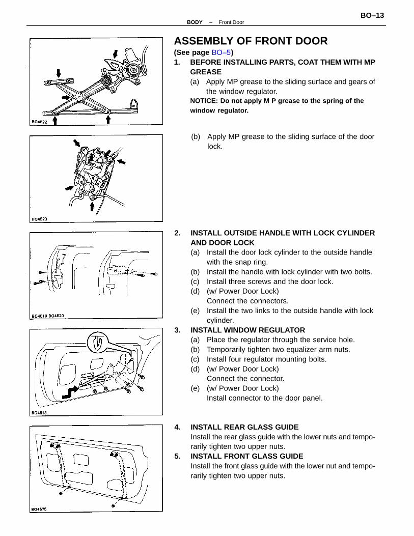
2. INSTALL OUTSIDE HANDLE WITH LOCK CYLINDERAND DOOR LOCK(a) Install the door lock cylinder to the outside handle
with the snap ring.(b) Install the handle with lock cylinder with two bolts.(c) Install three screws and the door lock.(d) (w/ Power Door Lock)
Connect the connectors.(e) Install the two links to the outside handle with lock
cylinder.3. INSTALL WINDOW REGULATOR
(a) Place the regulator through the service hole.(b) Temporarily tighten two equalizer arm nuts.(c) Install four regulator mounting bolts.(d) (w/ Power Door Lock)
Connect the connector.(e) (w/ Power Door Lock)
Install connector to the door panel.
ASSEMBLY OF FRONT DOOR(See page BO–5)1. BEFORE INSTALLING PARTS, COAT THEM WITH MP
GREASE(a) Apply MP grease to the sliding surface and gears of
the window regulator.NOTICE: Do not apply M P grease to the spring of thewindow regulator.
4. INSTALL REAR GLASS GUIDEInstall the rear glass guide with the lower nuts and tempo-rarily tighten two upper nuts.
5. INSTALL FRONT GLASS GUIDEInstall the front glass guide with the lower nut and tempo-rarily tighten two upper nuts.
(b) Apply MP grease to the sliding surface of the doorlock.
–BODY Front DoorBO–13

10. INSTALL DOOR MIRROR BRACKET(a) Place the door mirror bracket in the panel and tempo-
rarily tighten the stud bolt with nut and two bolts.(b) Install the clip to the moulding.
11. INSTALL DOOR WEATHERSTRIP12. INSTALL REAR VIEW MIRROR
(a) Install three screws with the mirror.(b) (w/ Remote Control Mirror)
Connect the connector.
7. INSTALL TWO DOOR TRIM SUPPORTSInstall the door trim supports and temporarily tighten twobolts.
8. INSTALL TWO DOOR GLASS STOPPERSInstall the door glass stoppers and temporarily tightentwo bolts.
6. INSTALL DOOR GLASSInstall the door glass to the regulator with two glassmounting nuts.HINT: Install a shop rag inside the panel to preventscratching the glass.
9. INSTALL FRONT DOOR BELT MOULDING(a) Insert the claw of the clips into the upper panel slit
and push the moulding onto the panel.(b) Install the clip to the moulding.
–BODY Front DoorBO–14

[In left/right direction–upperside of glass]Using a hexagon wrench, adjust the stud bolts (a) of therear glass guide. For example, if you turn right both studbolts, the upper side of the glass move to outside.HINT: Turn both stud bolts of the glass guide an equalamount.
[In forward/rearward direction]Loosen the two nuts and slide the rear glass guide (b)forward or rearward to adjust the glass.
[In vertical direction]Adjust the door glass stopper (c).
[In lean of forward/rearward direction]Adjust the equalizer arm bracket mounting bolts (d).
14. TIGHTEN EACH BOLT, NUT OF EACH PARTHINT: When installing the FR guide, after adjustingeach part, temporarily tighten the two nuts (e) until theytouch the inner panel surface.Then install the lock plate and tighten the bolt.
15. CHECK DOOR GLASS(a) When you close the door with the glass fully closed
check that the A–A, B–B, C–C sections are in thesame condition as shown in the illustration.
(b) When you close the door with the glass fully closed,be careful that the glass is not caught in the weather-strip.
(c) When you raise up the glass, check that the glassand the roof weatherstrip retainer are parallel andthe front and rear door glass stoppers touch at thesame time.
13. ADJUST DOOR GLASS
–BODY Front DoorBO–15

16. INSTALL SERVICE HOLE COVER(a) (w/ Speaker)
Install the service hole cover with four screws.(b) Connect the inside open link and locking link with
door lock.(c) Install the intermediate clip to the link.(d) Install the service hole cover with adhesive.HINT: Bring out the two links through the service holecover.(e) Insert the lower edge of the cover into the panel slit.(f) Seal the panel slit with cotton tape.NOTICE: Do not block the trim clip seating with thetape.
(d) When you raise up the glass to the middle, checkthat the gap of the glass is not big in the door trimsupport.
(e) Check that the glass move smoothly.If the above conditions are not met, readjust theglass.
(g) (w/ Speaker)Connect the connector and install the speaker withthree bolts.
–BODY Front DoorBO–16

17. INSTALL OPENING AND LOCKING CONTROL LINKAND INSIDE HANDLE(a) Connect the opening and locking control link with
inside handle and tighten it to the door.(b) Put the locking link in lock position as shown in the
drawing and connect the link to the clip.(c) Check that the locking and opening operation oc-
curs smoothly.
18. INSTALL FOLLOWING PARTS:(a) Door trim(b) Door inside handle bezel(c) (w/o Power Window)
Regulator handle
–BODY Front DoorBO–17

Luggage Compartment Damper StayNOTICE: Handling the damper.
(a) Do not disassemble the damper because the cylin-der is filled with pressurized gas.
(b) If the damper is to be replaced, drill a 2.0– 3.0 mm(0.079 – 0.118 in.) hole in the bottom of the removeddamper cylinder to completely release thehigh–pressure gas before disposing of it.
(c) When drilling, chips may fly out so work carefully(d) The gas is colorless, odorless and non–toxic.(e) When working, handle the damper carefully
Never score or scratch the exposed part of thepiston rod, and never allow paint or oil to get or it.
(f) Do not turn the piston rod and cylinder with thedamper fully extended.
LUGGAGE COMPARTMENT LIDADJUSTMENT OF LUGGAGECOMPARTMENT LID1. ADJUST LID IN FORWARD/REARWARD AND LEFT/
RIGHT DIRECTIONSAdjust the lid by loosening the lid side hinge bolts.
2. ADJUST LID IN VERTICAL DIRECTIONAdjust the lid by increasing or decreasing the number ofthe shims.
3. ADJUST LOCK(a) Adjust the lock position by slightly loosening the
mounting screws, and hitting the lock with a plastichammer.
(b) Tighten the mounting screws again.
4. ADJUST DOOR LOCK STRIKER(a) Loosen the mounting bolts to adjust the lock striker.(b) Using a plastic hammer, tap the striker to adjust it.
–BODY Luggage Compartment LidBO–18

ADJUSTMENT OF BACK DOOR1. ADJUST DOOR IN FORWARD/REARWARD AND
LEFT/RIGHT DIRECTIONSAdjust the door by loosening the hinge bolts.
2. ADJUST DOOR IN VERTICAL DIRECTIONAdjust the door by increasing or decreasing the numberof the shims.
BACK DOOR (Liftback)COMPONENTS
–BODY Back DoorBO–19

4. ADJUST LOCK(a) Adjust the lock position by slightly loosening the
lock mounting screws, and hitting the lock with aplastic hammer.
(b) Tighten the lock mounting screws again.
3. ADJUST DOOR LOCK STRIKER(a) Loosen the mounting bolts to adjust the lock striker.(b) Using a plastic hammer, tap the striker to adjust it.
Back Door Damper Stay(See page BO–18)
–BODY Back DoorBO–20

REMOVAL OF WINDSHIELD MOULDING1. REMOVE WIPER ARMS2. REMOVE COWL LOUVER
(See step 2 on page BO–33)
3. REMOVE WINDSHIELD MOULDINGUsing a knife, cut off the moulding as shown.NOTICE: Do not damage the body with the knife.
MOULDINGWindshield MouldingPREPARE ITEMS LISTED
Auto glass sealer (Three cement black)
COMPONENTS
08833–00030
Part Name Part No.
–BODY MouldingBO–21
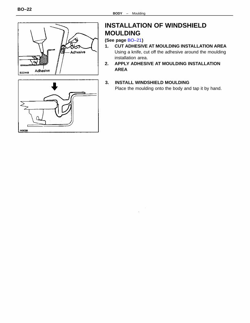
INSTALLATION OF WINDSHIELDMOULDING(See page BO–21)1. CUT ADHESIVE AT MOULDING INSTALLATION AREA
Using a knife, cut off the adhesive around the mouldinginstallation area.
2. APPLY ADHESIVE AT MOULDING INSTALLATIONAREA
3. INSTALL WINDSHIELD MOULDINGPlace the moulding onto the body and tap it by hand.
–BODY MouldingBO–22

Roof Drip MouldingREMOVAL1. REMOVE ROOF SIDE WEATHERSTRIP
(a) Using a clip remover, remove four clips from theweatherstrip.
(b) Remove the weatherstrip from the end with yourhand.
2. REMOVE ROOF SIDE WEATHERSTRIP REARRETAINERRemove three screws and the retainer.
3. REMOVE ROOF DRIP SIDE FINISH FRONTMOULDINGRemove ten screws and the moulding.
INSTALLATION1. INSTALL ROOF DRIP SIDE FINISH FRONT MOULDING
Install ten screws and the moulding.2. INSTALL ROOF SIDE WEATHERSTRIP REAR
RETAINERInstall three screws and the retainer.
Body Outside MouldingCOMPONENTS
–BODY MouldingBO–23

3. INSTALL ROOF SIDE WEATHERSTRIP(a) Install the weatherstrip to the moulding as shown.(b) Install four clips.
Front Door Belt MouldingREMOVAL1. REMOVE FRONT DOOR COMPONENT PARTS:
(See steps 1, 2, 3, 5 and 6 on pages BO–6 to 8)2. REMOVE FRONT DOOR BELT MOULDING
(See step 9 on page BO–9)
INSTALLATION1. INSTALL FRONT DOOR BELT MOULDING
(See step 9 on page BO–14)2. INSTALL FRONT DOOR COMPONENT PARTS:
(See steps 10, 12 and 18 on pages BO–14 and 17)
Quarter Window Glass withMouldingREMOVALLiftback: (See steps 1 to 9 on pages BO–39 to 40)Coupe: (See steps 1 to 7 on pages BO–42 to 43)
INSTALLATIONLiftback: (See steps 1 to 3 on pages BO–40 to 41)Coupe: (See steps 1 to 7 on pages BO–43 to 44)
Front Fender Mud GuardREMOVAL AND INSTALLATION1. REMOVE MUD GUARD
(a) Remove the screw.(b) Using a screwdriver, pry loose clips and remove the
mud guard.2. INSTALL MUD GUARD
(a) Install the mud guard onto the body.(b) Install the screw.
Side Mud GuardREMOVAL AND INSTALLATION1. REMOVE MUD GUARD
(a) Remove three screws.(b) Using a clip remover, pry loose the clips to remove
the mud guard.2. INSTALL MUD GUARD
(a) Align the clips of the guard with the grommet, theninstall the guard.
(b) Install three screws.
–BODY MouldingBO–24

Precautions for storing moulding material:• Store in cool place, avoiding direct sunlight, high tempera-
ture and dust.• The moulding is of polyvinyl chloride, so do not allow
it to come in contact with thinner or other solvent,open flame, or boiling water.
• The storage time for the moulding, adhesive andPrimer T is limited to about 9 months.
COMPONENTS
Side Protection MouldingTOOLS AND SUPPLIES
Cleaner (for cleaning body and removing body oil stains)Heat light
Adhesive (Super special)08850–00051 20g (0.71 oz.)
QuantityPart namePart No.
–BODY MouldingBO–25
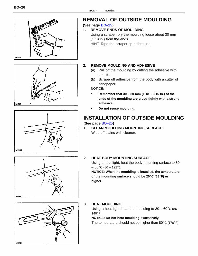
2. REMOVE MOULDING AND ADHESIVE(a) Pull off the moulding by cutting the adhesive with
a knife.(b) Scrape off adhesive from the body with a cutter of
sandpaper.NOTICE:
• Remember that 30 – 80 mm (1.18 – 3.15 in.) of theends of the moulding are glued tightly with a strongadhesive.
• Do not reuse moulding.
REMOVAL OF OUTSIDE MOULDING(See page BO–25)1. REMOVE ENDS OF MOULDING
Using a scraper, pry the moulding loose about 30 mm(1.18 in.) from the ends.HINT: Tape the scraper tip before use.
2. HEAT BODY MOUNTING SURFACEUsing a heat light, heat the body mounting surface to 30– 50°C (86 – 122T).NOTICE: When the moulding is installed, the temperatureof the mounting surface should be 20 °C (68°F) orhigher.
3. HEAT MOULDINGUsing a heat light, heat the moulding to 30 – 60°C (86 –140°F).NOTICE: Do not heat moulding excessively.
The temperature should not be higher than 80°C (176°F).
INSTALLATION OF OUTSIDE MOULDING(See page BO–25)1. CLEAN MOULDING MOUNTING SURFACE
Wipe off stains with cleaner.
–BODY MouldingBO–26

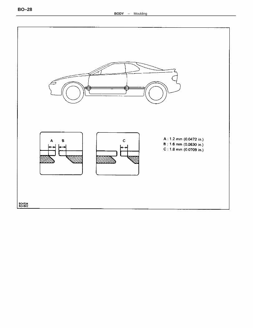
7. INSTALL MOULDING ALONG BODY PRESS LINEHINT: Before installing the moulding, remove thebacking paper on the edge of the moulding.Align the bosses on the moulding with the body holes,and push the moulding to the body.NOTICE:
• Be sure that the body and moulding are heated tothe proper temperature.
• Do not depress the adhesive–coated parts exces-sively just hold them down with your thumb.
• Scrape off any overflowing adhesive with a plasticspatula and clean the surface with a dry rang.
• After installation, do not wash the vehicle for 24hours.
4. COAT MOULDING WITH PRIMER ”T”Using a brush, coat both of the punched out ends of themoulding with Primer T.NOTICE:
• Let the Primer T dry for 30 seconds or more.• Do not touch the Primer T coating.
5. APPLY ADHESIVE TO MOULDINGApply adhesive to both punched out ends of the moulding.NOTICE: Install the moulding within 7 minutes afterapplying the adhesive.
6. LIFT MOULDING RELEASE SHEET FROM FACE OFMOULDINGNOTICE: When the moulding release sheet is removed, besure that no dirt or dust can get onto theuncoated area.
–BODY MouldingBO–27
–BODY MouldingBO–28

REMOVAL OF BACK WINDOW MOULDING1. REMOVE BACK WINDOW LOWER MOULDING
(a) Location of clips are as shown. Carefully apply adhe-sive tape to protect the body.
(b) Insert a scraper between the moulding and thebody, then remove the moulding.
HINT: Tape the scraper tip before use.
Back Window MouldingPREPARE ITEMS LISTED(See page BO–21)
–BODY MouldingBO–29

INSTALLATION OF BACK WINDOWMOULDING1. INSTALL BACK WINDOW MOULDING
Install the moulding in the same manner as the wind-shield moulding. (See page BO–22)
2. INSTALL BACK WINDOW LOWER MOULDINGPlace the moulding to the clips, then tap the moulding toinstall it.
2. REMOVE BACK WINDOW MOULDINGRemove the moulding in the same manner as the wind-shield moulding. (See page BO–21)
–BODY MouldingBO–30
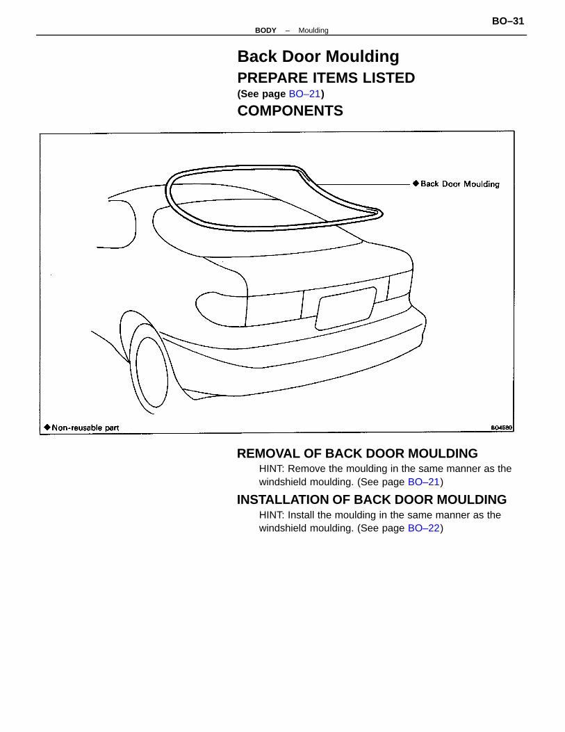
REMOVAL OF BACK DOOR MOULDINGHINT: Remove the moulding in the same manner as thewindshield moulding. (See page BO–21)
INSTALLATION OF BACK DOOR MOULDINGHINT: Install the moulding in the same manner as thewindshield moulding. (See page BO–22)
Back Door MouldingPREPARE ITEMS LISTED(See page BO–21)
COMPONENTS
–BODY MouldingBO–31
3. CHECK ADHESIVE HARDENING TIMEAfter main and hardening agents are mixed, leak testsshould be made only after the hardening time haselapsed.Example: The hardening time for adhesive set No. 35with an ambient temperature of 25°C (77°F) is 2.5 hours.NOTICE: Do not drive the vehicle until at least doublethe hardening time has elapsed.
2. CHECK ADHESIVE USABLE TIMEAfter the mixing main and hardening agents, finish glassinstallation within the specified time as shown.Example: For glass installation in an ambient tempera-ture of 25°C (77°F), apply adhesive set No. 35 within 45minutes.
Main agent 500g (17.64 oz.)hardening agent 75g (2.65 oz)Primer G (for glass) 20g (0.71 oz.)Primer M (for body) 20g (0.71 oz)Sponge (for applying primer)Piano wire 0.6 mm dia. x 1 m (0.024 x 39.37 in.)Cartridge
Sealant gun (for applying adhesive)Glass or steel sheet (for mixing adhesive)Putty spatula (for mixing adhesive and correctingadhered parts)Cleaner (for cleaning adhering surface)
1. CHOOSE SUITABLE ADHESIVE SETUse an adhesive set suitable for the ambient temperature.
Adhesive set08850–00070(0–15°C or 32–59°F)08850–00080(15–35°C or 59–95°F)08850–00090(35–45°C or 95–113°F)
WINDSHIELDPREPARE ITEMS LISTED
DamDouble–sided tape (for sticking on dam)
1 ea.1 ea.1 ea.1 ea.2 ea.1 ea.1 set.
Windshield glassadhesive setNo. 15
Windshield glassadhesive setNo. 35
Windshield glassadhesive setNo. 45
Dam kit04562–12010
Ambienttemperature
Part name and No. Contents of set
08850–00080
08850–00090
08850–00070
Part name
Quantity
Part No.
–BODY WindshieldBO–32

REMOVAL OF WINDSHIELD1. REMOVE WIPER ARMS
Remove two nuts and the wiper arms.2. REMOVE COWL LOUVER
(a) Remove five screws and six clips from the louver.(b) Remove the louver.
3. REMOVE FRONT PILLAR GARNISH(a) Remove the clips by your hand.(b) Pull out the garnish from the roof side inner garnish.(c) Pull the garnish backward to remove it.
COMPONENTS
–BODY WindshieldBO–33
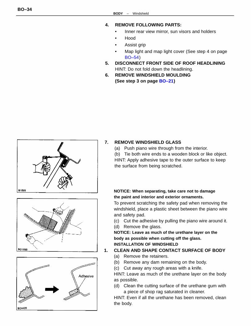
NOTICE: When separating, take care not to damagethe paint and interior and exterior ornaments.
To prevent scratching the safety pad when removing thewindshield, place a plastic sheet between the piano wireand safety pad.(c) Cut the adhesive by pulling the piano wire around it.(d) Remove the glass.NOTICE: Leave as much of the urethane layer on thebody as possible when cutting off the glass.INSTALLATION OF WINDSHIELD
1. CLEAN AND SHAPE CONTACT SURFACE OF BODY(a) Remove the retainers.(b) Remove any dam remaining on the body.(c) Cut away any rough areas with a knife.HINT: Leave as much of the urethane layer on the bodyas possible.(d) Clean the cutting surface of the urethane gum with
a piece of shop rag saturated in cleaner.HINT: Even if all the urethane has been removed, cleanthe body.
4. REMOVE FOLLOWING PARTS:• Inner rear view mirror, sun visors and holders
• Hood
• Assist grip
• Map light and map light cover (See step 4 on pageBO–54)
5. DISCONNECT FRONT SIDE OF ROOF HEADLININGHINT: Do not fold down the headlining.
6. REMOVE WINDSHIELD MOULDING(See step 3 on page BO–21)
7. REMOVE WINDSHIELD GLASS(a) Push piano wire through from the interior.(b) Tie both wire ends to a wooden block or like object.HINT: Apply adhesive tape to the outer surface to keepthe surface from being scratched.
–BODY WindshieldBO–34

6. COAT CONTACT SURFACE OF BODY WITH PRIMERI’MUsing a brush, coat the contact surface on the body withPrimer M.NOTICE:
• Let the Primer coating dry for 10 minutes or more.Make sure that the installation of the glass is finishedwithin 2 hours.
• Use care not to leave any part of the contact surfaceuncoated or excessively coated, as Primer M and Gserve to boost the adhesive power of the urethane tothe glass or body.
• Do not keep any of the opened Primer M and G forlater use.
3. POSITION GLASS(a) Place glass in correct position.(b) Check that all contacting parts of the glass rim are
perfectly even and do not make contact with thefasteners.
(c) Place reference marks between the glass and body.(d) Remove the glass.
2. CLEAN REMOVED GLASS BEFORE INSTALLATION(a) Using a scraper, remove the urethane gum sticking
to the glass.(b) Clean the glass with cleaner.NOTICE: Do not touch the glass after cleaning it.
4. CLEAN CONTACT SURFACE OF GLASSUsing cleaner, clean the contact surface black–coloredarea around the entire glass rim.NOTICE: Do not touch the glass face after cleaning it.
5. INSTALL DAMInstall the dam with double–sided tape as shown in thedrawing.NOTICE: Do not touch the glass face after cleaning it.
–BODY WindshieldBO–35

8. MIX ADHESIVE COATINGNOTICE:
• Be sure that installation of the glass is finishedwithin usable time. (See step 2 on page BO–32)
• The mixture should be made in 5 minutes or less.(a) Thoroughly clean the glass plate and putty spatula
with solvent.(b) thoroughly mix 500 g (117.64 oz.) of the main agent
and 75 g (2.65 oz.) of the hardening agent on aglass plate or like object with a putty spatula.
9. APPLY ADHESIVE(a) Cut off the tip of the cartridge nozzle to make a hole
5 mm (0.20 in.) in diameter. Fill the cartridge withadhesive.
(b) Load the cartridge into the sealer gun.(c) Coat the glass with adhesive on all contact surfaces
along the ridge.Adhesive height:
If adhesive remains on body 3.5 – 5.0 mm (0.138 – 0.197 in.)If no adhesive remains on body 8 –10 mm (0.31 – 0.39 in.)
10. INSTALL GLASSHINT: Confirm that the dam is attached the body panelas shown in the drawing.
7. COAT CONTACT SURFACE OF GLASS WITH PRIMER”G”(a) Using a brush or sponge, coat the edge of the glass
and the contact surface with Primer G.(b) Before the Primer dries, wipe it off with a clean
cloth.NOTICE: Be sure that installation of the glass is finishedwithin 70 minutes.
(a) Position the glass so that the reference marks arelined up, and press in gently along the rim.
(b) Using a spatula, apply adhesive on the glass rim.(c) Use a spatula to remove any excess or protruding
adhesive.(d) Fasten glass securely until the adhesive sets.
–BODY WindshieldBO–36

12. INSTALL FOLLOWING PARTS:• Windshield moulding (See page BO–22)
• Front side of roof headlining and assist grip
• Map light and map light cover
• Inner rear view mirror, sun visors and holders
• Front pillar garnish, cowl louver and wiper arms13. INSTALL AND ADJUST HOOD
(See page BO–3)NOTICE: Wait at least twice the setting time beforedriving the car.
11. INSPECT FOR LEAKS AND REPAIR(a) Perform a leak test after the hardening time has
elapsed.(b) Seal any leaks with auto glass sealer.
Part No. 08833–00030 or equivalent
–BODY WindshieldBO–37

Butyl tape 9 mm dia. x 2,500 mm (0.35 x 98.43 in.)Primer 5 cc (0.17 fl.oz.)Sponge (for applying primer)Piano wire 1 mm dia. x 600 mm (0.04 x 23.62 in.) (for slicing off glass)
QUARTER WINDOW GLASS(Liftback)PREPARE ITEMS LISTED
Cleaner (for cleaning adhering surfaces)
Butyl tape set(08850–00065)
COMPONENTS
Materials required
Part Name and No. Contents of Set
–BODY Quarter Window Glass (Liftback)BO–38

REMOVAL OF QUARTER WINDOW GLASS(See page BO–38)1. REMOVE FOLLOWING PARTS:
(a) Package tray trim panel(b) Rear side of scuff plate(c) Rear seat cushion and back (See page BO–66)
2. REMOVE DECK TRIM REAR COVER(a) Using a clip remover, remove two clips.(b) Pull the cover upwards to remove it.
3. REMOVE DECK TRIM SIDE PANEL(a) Using the screwdriver, pry loose the clips.(b) Remove the panel.(c) Disconnect the connector.
5. REMOVE QUARTER TRIM PANEL(a) Remove two bolts and the seat back hinge.(b) Remove the five screws and pry out the clips to
remove the panel.
4. REMOVE SPEAKER GRILLEUsing a screwdriver, remove the speaker grille.HINT: Tape the screwdriver tip before use.
6. REMOVE FRONT SEAT SHOULDER ANCHOR BOLT7. REMOVE REAR SEAT SHOULDER ANCHOR BOLT
–BODY Quarter Window Glass (Liftback)BO–39

INSTALLATION OF QUARTERWINDOW G LASS(See page BO–38)1. CLEAN BODY OR GLASS
Wipe off any adhesive left on the body or moulding withcleaner.
9. REMOVE QUARTER WINDOW GLASS WITHMOULDING(a) Remove the three nuts.(b) Using a knife, cut loose the adhesive.(c) Remove the glass.NOTICE: Do not damage the body.
2. INSTALL QUARTER WINDOW GLASS WITHMOULDING(a) Using a sponge, apply the primer on the contact
surface of moulding.(b) Let the primer coating dry for 10 minutes.
8. REMOVE ROOF SIDE INNER GARNISH(a) Remove the screw and hook.(b) Remove the three screws.(c) Using the screwdriver, pry out the clips.(d) Remove the roof side inner garnish.
(c) Install the seal to the glass.(d) Install the window glass to the body.(e) Install three nuts.
–BODY Quarter Window Glass (Liftback)BO–40

3. INSTALL FOLLOWING PARTS:(a) Roof side inner garnish(b) Rear shoulder anchor bolt and guideTorque: 43 N–m (440 kgf–cm, 32 ft–lbf)
(c) Quarter trim panel(d) Front shoulder anchor bolt and guideTorque: 43 N–m (440 kgf–cm, 32 ft–lbf)
(e) Deck trim side panel(f) Speaker grille(g) Rear seat cushion and back (See page BO–66)(h) Scuff plate(i) Deck trim rear panel(j) Package tray trim cover
–BODY Quarter Window (Liftback)BO–41

3. REMOVE QUARTER TRIM PANEL(a) (w/ Separate Seat)
Remove two bolts and rear seat side hinge.(b) Using the screwdriver, remove speaker grille.HINT: Tape the screwdriver tip before use.(c) Remove six screws.(d) Using the screwdriver, pry loose the clips and re-
move the quarter trim panel.
REMOVAL OF QUARTER WINDOW GLASS1. REMOVE REAR SIDE OF SCUFF PLATE2. REMOVE REAR SEAT BACK AND CUSHION
(See page BO–66)
(Coupe)PREPARE ITEMS LISTED(See page BO–38)
COMPONENTS
–BODY Quarter Window Glass (Coupe)BO–42

INSTALLATION OF QUARTERWINDOW GLASS(See page BO–42)1. CLEAN BODY OR GLASS
Wipe off any adhesive left on the body or moulding withcleaner.
6. REMOVE ROOF SIDE INNER GARNISH(a) Remove the screw and the hook.(b) Remove the three screws.(c) Using the screwdriver, pry loose the clips.(d) Remove the roof side inner garnish.
7. REMOVE QUARTER WINDOW GLASS ANDMOULDING(a) Remove three nuts.
4. REMOVE FRONT SHOULDER BELT ANCHOR BOLT5. REMOVE REAR SHOULDER BELT ANCHOR BOLT
(b) Using a knife, cut loose the adhesive.(c) Remove the glass.
NOTICE: Do not damage the body.
–BODY Quarter Window Glass (Coupe)BO–43

3. INSTALL ROOF SIDE INNER GARNISH4. INSTALL QUARTER TRIM PANEL5. INSTALL FRONT AND REAR SHOULDER BELT
ANCHOR BOLT AND GUIDETorque: 43 N–m (440 kgf–cm, 32 ft–lbf)
6. INSTALL REAR SEAT CUSHION AND BACK(See page BO–66)
7. INSTALL SCUFF PLATE
2. INSTALL QUARTER WINDOW GLASS(a) Using a sponge, apply the primer on the contact
surface of moulding.(b) Let the primer coating dry for 10 minutes.
(c) Install the seal to the glass.(d) Install the window glass to the body.(e) Install three nuts.
–BODY Quarter Window Glass (Coupe)BO–44

REMOVAL OF BACK WINDOW GLASS1. REMOVE FOLLOWING PARTS:
(a) Rear seat cushion and back (See page BO–66)(b) Quarter trim panel (See step 3 on page BO–42)(c) Front and rear shoulder belt anchor bolts and
guides.(d) Roof side inner garnish (See step 6 on page BO–43)
2. DISCONNECT DEFOGGER WIRE CONNECTORS3. REMOVE HIGH MOUNT STOP LIGHT AND COVER
(a) Pry loose the cover with your hand.(b) Remove two bolts and the light.(c) Disconnect the connector.
BACK WINDOW GLASSPREPARE ITEMS LISTED(See page BO–31)
COMPONENTS
–BODY Back Window GlassBO–45

5. REMOVE ROOF HEADLINING REAR TRIMUsing a screwdriver, pry loose the clips to remove thetrim.HINT: Tape the screwdriver tip before use.
6. REMOVE BACK WINDOW MOULDINGS(See steps 1 to 2 on pages BO–29 to 30)
7. REMOVE BACK WINDOW GLASSRemove the glass in the same manner as windshield.(See step 7 on page BO–34)
INSTALLATION OF BACK WINDOW GLASS(See page BO–45)1. CLEAN AND SHAPE CONTACT SURFACE OF BODY
(See step 1 on page BO–34)2. CLEAN REMOVED GLASS BEFORE INSTALLATION
(See step 2 on page BO–35)3. POSITION GLASS
(See step 3 on page BO–35)4. CLEAN CONTACT SURFACE OF GLASS
(See step 4 on page BO–35)5. INSTALL DAM
Install the dam with double–sided tape as shown in thedrawing.NOTICE: Do not touch the glass face after cleaning it.
6. COAT CONTACT SURFACE OF BODY WITH PRIMERM(See step 6 on page BO–35)
7. COAT CONTACT SURFACE OF GLASS WITH PRIMERG(See step 7 on page BO–36)
8. MIX ADHESIVE COATING(See step 8 on page BO–36)
9. APPLY ADHESIVE(See step 9 on page BO–36)
4. REMOVE PACKAGE TRAY TRIMPull the trim forward to remove it.
–BODY Back Window GlassBO–46

10. INSTALL GLASS(See step 10 on page BO–36)
11. INSTALL BACK WINDOW MOULDINGS(See steps 1 to 2 on page BO–30)HINT: Before the glass adhesive is hardened, install themoulding.
12. INSPECT FOR LEAKS AND REPAIR(See step 11 on page BO–37)
13. INSTALL FOLLOWING PARTS:(a) Roof headlining rear trim(b) Package tray trim(c) High mount stop light and cover(d) Roof side inner garnish(e) Front and rear seat belt shoulder anchor boltTorque: 43 N–m (440 kgf–cm, 32 ft–lbf)
(f) Quarter trim panel(g) Rear seat back and cushion
(See page BO–66)
–BODY Back Window GlassBO–47

REMOVAL OF BACK DOOR GLASS1. REMOVE WIPER ARM2. DISCONNECT DEFOGGER WIRE CONNECTORS3. REMOVE HIGH MOUNT STOP LIGHT AND COVER
(a) Using a screwdriver, remove the clips.(b) Remove four bolts and the light.(c) Disconnect the connector.
4. REMOVE BACK DOOR SIDE TRIMUsing a screwdriver, pry loose the clips to remove thetrim.HINT: Tape the screwdriver tip before use.
BACK DOOR GLASSPREPARE ITEMS LISTED(See page BO–32)
–BODY Back Door GlassBO–48

8. REMOVE BACK DOOR GLASS(a) Remove four nuts.(b) Remove the glass in the same manner as the wind-
shield glass.NOTICE: Do not damage the retainers as shown withthe piano wire.
INSTALLATION OF BACK DOOR GLASS(See page BO–48)
1. CLEAN AND SHAPE CONTACT SURFACE OF BODY(See step 1 on page BO–34)
2. CLEAN REMOVED GLASS BEFORE INSTALLATION(See step 2 on page BO–35)
3. POSITION GLASS (See step 3 on page BO–35)4. CLEAN CONTACT SURFACE OF GLASS
(See step 4 on page BO–35)5. COAT CONTACT SURFACE OF BODY WITH PRIMER
”M” (See step 6 on page BO–35)6. COAT CONTACT SURFACE OF GLASS WITH
PRIMER ”G” (See step 7 on page BO–36)7. MIX ADHESIVE COATING
(See step 8 on page BO–36)8. APPLY ADHESIVE (See step 9 on page BO–36)9. INSTALL GLASS (See step 10 on page BO–36)
HINT: Align the bolts of retainer with the body holes,then install the glass with four nuts.
6. REMOVE BACK DOOR TRIMUsing the screwdriver, pry loose the clips to remove thetrim.
7. REMOVE BACK DOOR MOULDING(See page BO–31)
5. REMOVE BACK DOOR UPPER TRIM(a) Remove two screws and two clips.(b) Using the screwdriver, pry loose the clips to remove
the trim.
–BODY Back Door GlassBO–49

10. INSTALL BACK DOOR MOULDING(See page BO–31)HINT: Before the glass adhesive is hardened, install themoulding.
11. INSPECT FOR LEAKS AND REPAIR(See step 11 on page BO–37)
12. INSTALL FOLLOWING PARTS:(a) Back door trim(b) Back door upper trim(c) Back door side trim(d) High mount stop light and cover(e) Wiper arm
13. CONNECT DEFOGGER WIRE CONNECTORS
–BODY Back Door GlassBO–50
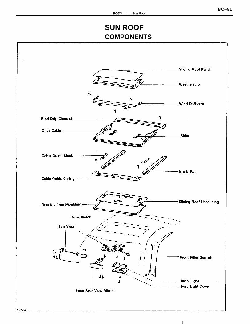
SUN ROOFCOMPONENTS
–BODY Sun RoofBO–51

ON–VEHICLE INSPECTIONINSPECT SLIDING ROOF PANEL ALIGNMENT
(a) Start the engine and check the operation time of themoon roof.Operation time: Approx. 5 secs.
(b) Check for abnormal noise or binding during operation.(c) With the sun roof fully closed, check for water leakage.(d) Check for a difference in level between the sliding
panel and roof panel.Front side: –0.9 ± 1 mm (–0.035± 0.039 in.)Rear side: 0.1 ± 1 mm (0.004 ± 0.039 in.)If the sliding roof does not operate:(a) Remove the control switch cover.(b) Remove the motor screw inside.CAUTION: Be careful not to lose the shims.
(c) Manually operate the sun roof by inserting a specialcrank–shaped screwdriver into the hole and turning thedrive shaft.
ADJUSTMENT OF SLIDING ROOF1. SLIDE SLIDING ROOF HEADLINING BACKWARD
(a) Tilt up the panel 10 – 20 mm (0.39 – 0.79 in.).(b) Push up the left and light levers above the headlining.
2. TO ADJUST LEVEL DIFFERENCE(a) Tilt down the panel.(b) Adjust by increasing or decreasing the number o
shims.HINT: If the front of the sliding roof is high, even without a shoe shim, it will not close completely.
(c) Slide the headlining backward.
–BODY Sun RoofBO–52

If the difference is about 2 mm (0.08 in.):(a) Remove the drive motor and shift the cable one
notch.(b) Reinstall the motor.
3. TO ADJUST FORWARD OR REARWARDAdjust by loosening the sliding roof installation bolts,and move the sliding roof panel forward and rearward.
HINT: With the sliding roof closed, insert a pin or likeobject into the base hole to insure alignment of theholes.
4. TO ADJUST CLEARANCE(Difference in left and right clearance)
–BODY Sun RoofBO–53

REMOVAL OF SLIDING ROOF(See page BO–49)1. TILT UP SLIDING ROOF PANEL2. SLIDE SLIDING ROOF HEADLINING
(See step 1 on page BO–52)3. DISCONNECT BATTERY CABLE FROM NEGATIVE
USA:CAUTION: Work must be started after approx. 20seconds or longer from the time the ignition switch isturned to the ”LOCK” position and the negative (–) termi-nal cable is disconnected from the battery.
4. REMOVE MAP LIGHT(a) Remove a screw and the map light cover.(b) Remove a screw and the map light.(c) Disconnect the connector.
5. REMOVE FOLLOWING PARTS:(a) Assist grip(b) Front pillar garnish (See step 3 on page BO–33)(c) Sun visor and holder(d) Inner rear view mirror(e) Opening trim moulding
6. REMOVE DRIVE MOTOR(a) Push down the front side of roof headlining.(b) Disconnect the drive motor connectors.(c) Remove three bolts and drive motor.
7. REMOVE SLIDING ROOF PANEL(a) Remove the six sliding roof installation nuts and
shims.HINT: Be sure the number of shims.(b) Pull the panel upward to remove it.
If the difference is about 1 mm (0.04 in.): Loosen thesliding roof rear shoe installation nuts and readjust thesliding roof to the proper position.
–BODY Sun RoofBO–54

DISASSEMBLY OF SLIDING ROOF(See page BO–51)1. REMOVE SLIDING ROOF HEADLINING2. REMOVE CABLE GUIDE CASING FROM CASING
ASSEMBLY(a) Remove two set screws.(b) Pull the cable guide casing forward to remove.
10. REMOVE CABLE GUIDE CASING ASSEMBLY(a) Slide the drive cable forward and remove the eight
set screws.
(b) Apply adhesive tape to protect the body.(c) Pull the cable guide casing assembly off in forward
direction.
9. REMOVE WIND DEFLECTOR(a) Slide the drive cable rearward.(b) Remove four screws and the deflector.
8. REMOVE ROOF DRIP CHANNEL(a) Remove two screws.(b) Pull the channel forward to remove it.
–BODY Sun RoofBO–55

INSTALLATION OF SLIDING ROOF(See page BO–51)1. INSTALL CABLE GUIDE CASING ASSEMBLY ONTO
ROOF(a) While pushing down on the center of the casing,
insert the cable guide casing assembly from thefront of the roof.
(b) Install eight set screws.(c) Align the alignment marks.
ASSEMBLY OF SLIDING ROOF(See page BO–51)1. APPLY MP GREASE TO DRIVE CABLE2. PLACE DRIVE CABLES INTO GUIDE RAIL3. INSTALL CABLE GUIDE BLOCK TO GUIDE RAIL
4. INSTALL CABLE GUIDE CASING AND GUIDE RAIL(a) Insert the drive cable into the casing, and align it
with the guide rail.(b) Install the guide rail and guide casing with the
screws.
(c) Use butyl tape to cover the cut portion of the weath-erstrip at the connection between the guide casingand guide rail.
5. INSTALL SLIDING ROOF HEADLINING
3. REMOVE CABLE FROM GUIDE RAIL(a) Remove two screws and the cable guide block from
the guide rail.(b) Pull the drive cable from the guide rail.
–BODY Sun RoofBO–56
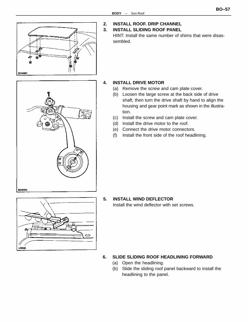
4. INSTALL DRIVE MOTOR(a) Remove the screw and cam plate cover.(b) Loosen the large screw at the back side of drive
shaft, then turn the drive shaft by hand to align thehousing and gear point mark as shown in the illustra-tion.
(c) Install the screw and cam plate cover.(d) Install the drive motor to the roof.(e) Connect the drive motor connectors.(f) Install the front side of the roof headlining.
2. INSTALL ROOF. DRIP CHANNEL3. INSTALL SLIDING ROOF PANEL
HINT: Install the same number of shims that were disas-sembled.
6. SLIDE SLIDING ROOF HEADLINING FORWARD(a) Open the headlining.(b) Slide the sliding roof panel backward to install the
headlining to the panel.
5. INSTALL WIND DEFLECTORInstall the wind deflector with set screws.
–BODY Sun RoofBO–57

7. INSTALL FOLLOWING PARTS:• Assist grip
• Front pillar garnish
• Sun visor and holder
• Inner rear view mirror
• Opening trim moulding8. INSTALL MAP LIGHT
(a) Connect the connector.(b) Install the screw and the map light.(c) Install the screw and the map light cover.
9. CONNECT BATTERY CABLE TO NEGATIVE TERMINAL
–BODY Sun RoofBO–58
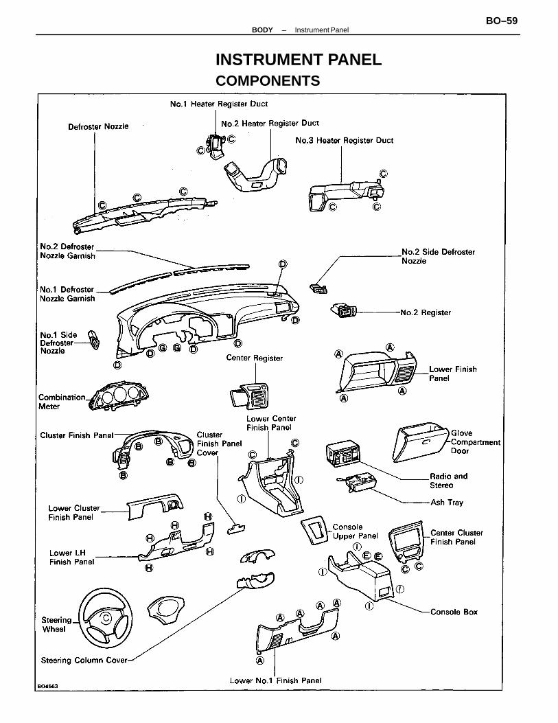
INSTRUMENT PANELCOMPONENTS
–BODY Instrument PanelBO–59

REMOVAL OF SAFETY PAD(See page BO–59)1. DISCONNECT BATTERY CABLE FROM NEGATIVE
TERMINALUSA:CAUTION: Work must be started after approx. 20seconds or longer from the time the ignition switch isturned to the ”LOCK” position and the negative (–) termi-nal cable is disconnected from the battery.
2. REMOVE STEERING WHEELUSA (See page SR–5)CANADA (See page SR–6)
3. REMOVE STEERING COLUMN COVERRemove four screws and column covers.
4. REMOVE CONSOLE BOX(a) Remove console upper panel.(b) Using a screwdriver, remove four screw caps.HINT: Tape the screwdriver tip before use.(c) Remove four screws and two bolts.(d) Disconnect the connectors and remove the console
box.
HINT: Screw sizes in the previous illustration are indi-cated by following the code below for removal andinstallation of safety pad.
–BODY Instrument PanelBO–60

8. REMOVE CENTER CLUSTER FINISH PANEL, RADIOAND LOWER CENTER FINISH PANEL(a) Remove two screws.(b) Using the screwdriver, remove the center cluster fin-
ish panel and disconnect the connector.(c) Remove four screws from the radio.(d) Disconnect the connectors and the radio antenna
cable to remove the radio.
7. REMOVE LOWER NO.1 FINISH PANEL(a) Using the screwdriver, pry out the cluster finish
panel cover.(b) Remove scuff plate.(c) Remove six screws and the panel.
5. REMOVE LOWER FINISH PANEL(a) Remove the door scuff plate.(b) Remove four screws and the panel.(c) Disconnect the connectors.
6. REMOVE ENGINE HOOD RELEASE LEVERRemove two screws and the lever.
(e) Using the screwdriver, remove screw caps.(f) Remove four screws and the panel.
–BODY Instrument PanelBO–61

(w/ Speedometer Cable)11. REMOVE SPEEDOMETER CABLE
(a) Push on the pawls on the right and left of the meterbracket.
(b) Pull the meter bracket from the safety pad.
9. REMOVE CLUSTER FINISH PANEL(a) Remove the lower cluster finish panel.(b) Remove five screws and pull out the cluster finish
panel.
10. REMOVE COMBINATION METER(a) Remove four screws.(b) Disconnect the connectors and remove the meter.
12. REMOVE SAFETY PAD(a) Remove the five bolts and lower LH finish panel.
(b) Using the screwdriver, remove center register.(c) Disconnect the connector.
–BODY Instrument PanelBO–62

13. REMOVE FOLLOWING PARTS FROM SAFETY PAD(a) Defroster nozzle(b) No.1 defroster nozzle garnish(c) No.2 defroster nozzle garnish(d) No.1 side defroster nozzle(e) No.2 register(f) No.1 side defroster nozzle duct(g) No.1 instrument panel bracket(h) Center instrument panel bracket(i) No. 3 heater to register duct
(e) Using the screwdriver, remove No.2 side defrosternozzle.
(f) Remove six bolts and three nuts.
(d) Remove the clip and No.2 heater to register duct.
–BODY Instrument PanelBO–63

INSTALLATION OF SAFETY PAD(See page BO–59)INSTALL SAFETY PAD PARTS BY FOLLOWING REMOVALSEQUENCE IN REVERSE
–BODY Instrument PanelBO–64

SEATFront SeatCOMPONENTS
–BODY SeatBO–65

Rear SeatCOMPONENTS
–BODY SeatBO–66

SEAT BELTSCOMPONENTS
–BODY Seat BeltBO–67

SEAT BELT[Emergency Locking Retractor (ELR) TYPE]1. RUNNING TEST (IN SAFE AREA)
(a) Fasten the seat belt.(b) Drive the car at 16 km/h (10 mph) and make a very
hard stop.(c) Check that the belt is locked and cannot be ex-
tended at this time.HINT: Conduct this test in a safe area. If the belt does notlock, remove the belt mechanism assembly and conductthe following static check. Also, whenever installing anew belt assembly, verify proper operation beforeinstallation.
2. STATIC TEST(a) Remove the locking retractor assembly.(b) Tilt the retractor slowly.(c) Verify that the belt can be pulled out at a tilt of 15
degrees or less, and cannot be pulled out at over 45degrees of tilt.
If problem is found, replace the assembly.
–BODY Seat BeltBO–68

BODY DIMENSIONSGeneral Information1. BASIC DIMENSIONS
(a) There are two types of dimensions in the diagram.(Three–dimensional distance)
• Straight–line distance between the centers oftwo measuring points.
(Two–dimensional distance)
• Horizontal distance in forward/rearward between the centers of two measuring points.
• The height from an imaginary standard line.(b) Incases in which only one dimension is given,
left and right are symmetrical.(e) The dimensions in the following drawing indicate
actual distance. Therefore, please use the di-mensions as a reference.
HINT:1. The height of the left and right pointers must be
equal.2. Always calibrate the tracking gauge before measur-
ing or after adjusting the pointer height.3. Take care not to drip the tracking gauge or otherwise
shock it.4. Confirm that the pointers are securely in the holes.
2. MEASURING(a) Basically, all measurements are to be done with a
tracking gauge. For portions where it is not possibleto use a tracking gauge, a tape measure should beused.
(b) Use only a tracking gauge that has no looseness inthe body, measuring plate, or pointers.
(c) When using a tape measure, avoid twists and bendsin the tape.
(d) When tracking a diagonal measurement from thefront spring support inner hole to the suspensionmember upper rear installation hole, measure alongthe front spring support panel surface.
–BODY Body DimensionsBO–69

Body DimensionsENGINE COMPARTMENT
–BODY Body DimensionsBO–70

BODY OPENING AREAS (Side View)
–BODY Body DimensionsBO–71

UNDER BODY
–BODY Body DimensionsBO–72
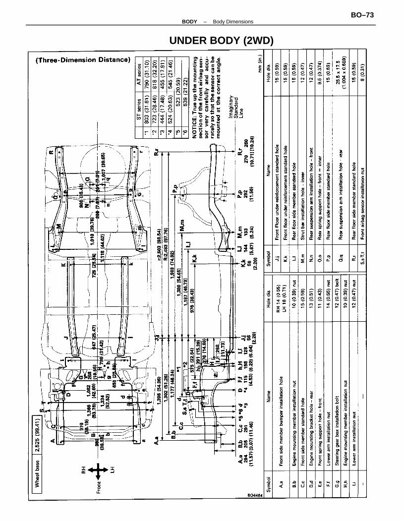
UNDER BODY (2WD)
–BODY Body DimensionsBO–73

UNDER BODY (4WD)
–BODY Body DimensionsBO–74

UNDER BODY (4WD)
–BODY Body DimensionsBO–75

LUGGAGE COMPARTMENT (Coupe)
–BODY Body dimensionsBO–76

LUGGAGE COMPARTMENT (Liftback)
–BODY Body dimensionsBO–77