bouwkundige informatiesystemen adms 2004 uml part 1 jan dijkstra - 2 augustus 2004
Post on 21-Dec-2015
218 views
TRANSCRIPT
Bouwkundige InformatiesystemenADMS 2004
UML part 1
Bouwkundige InformatiesystemenADMS 2004
UML part 1
Jan Dijkstra - 2 augustus 2004
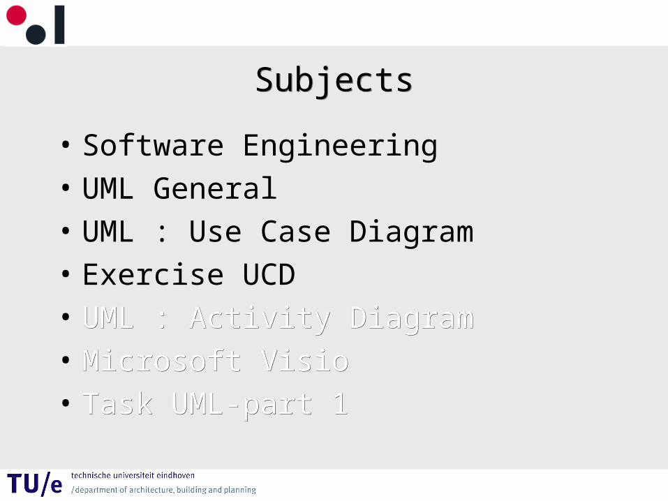
SubjectsSubjects
• Software Engineering
• UML General
• UML : Use Case Diagram
• Exercise UCD
• UML : Activity DiagramUML : Activity Diagram
• Microsoft VisioMicrosoft Visio
• Task UML-part 1Task UML-part 1
Software EngineeringSoftware Engineering
Sommerville, Ian (2001)
Software Engineering, 6th editionCh.1-3, 5
http://www.software-engin.com
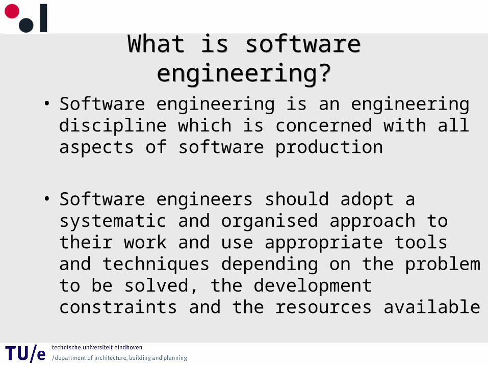
What is software engineering?What is software engineering?
• Software engineering is an engineering discipline which is concerned with all aspects of software production
• Software engineers should adopt a systematic and organised approach to their work and use appropriate tools and techniques depending on the problem to be solved, the development constraints and the resources available
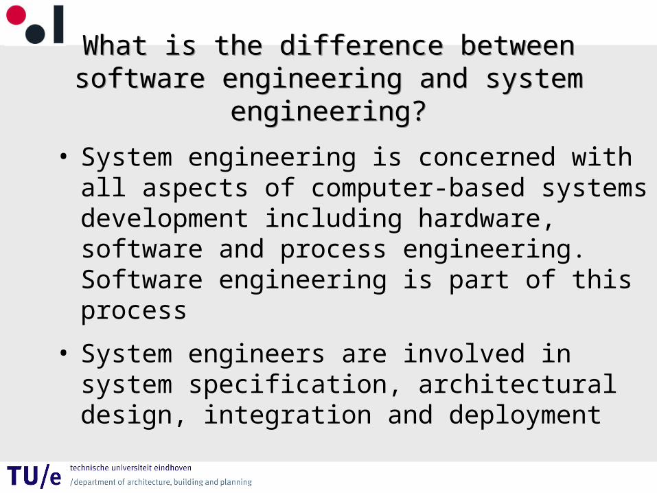
What is the difference between software engineering and system engineering?
What is the difference between software engineering and system engineering?
• System engineering is concerned with all aspects of computer-based systems development including hardware, software and process engineering. Software engineering is part of this process
• System engineers are involved in system specification, architectural design, integration and deployment
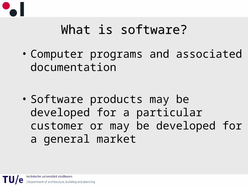
What is software?What is software?
• Computer programs and associated documentation
• Software products may be developed for a particular customer or may be developed for a general market
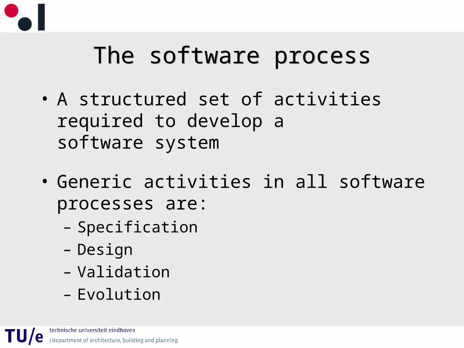
The software processThe software process
• A structured set of activities required to develop a software system
• Generic activities in all software processes are:– Specification– Design– Validation– Evolution
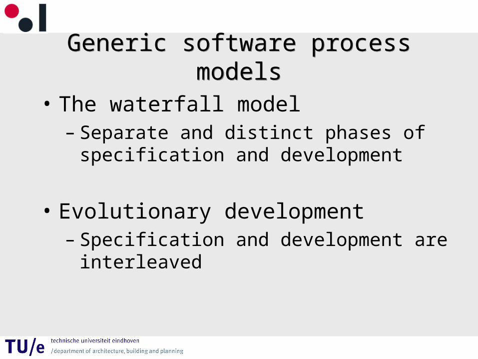
Generic software process modelsGeneric software process models
• The waterfall model– Separate and distinct phases of specification
and development
• Evolutionary development– Specification and development are interleaved
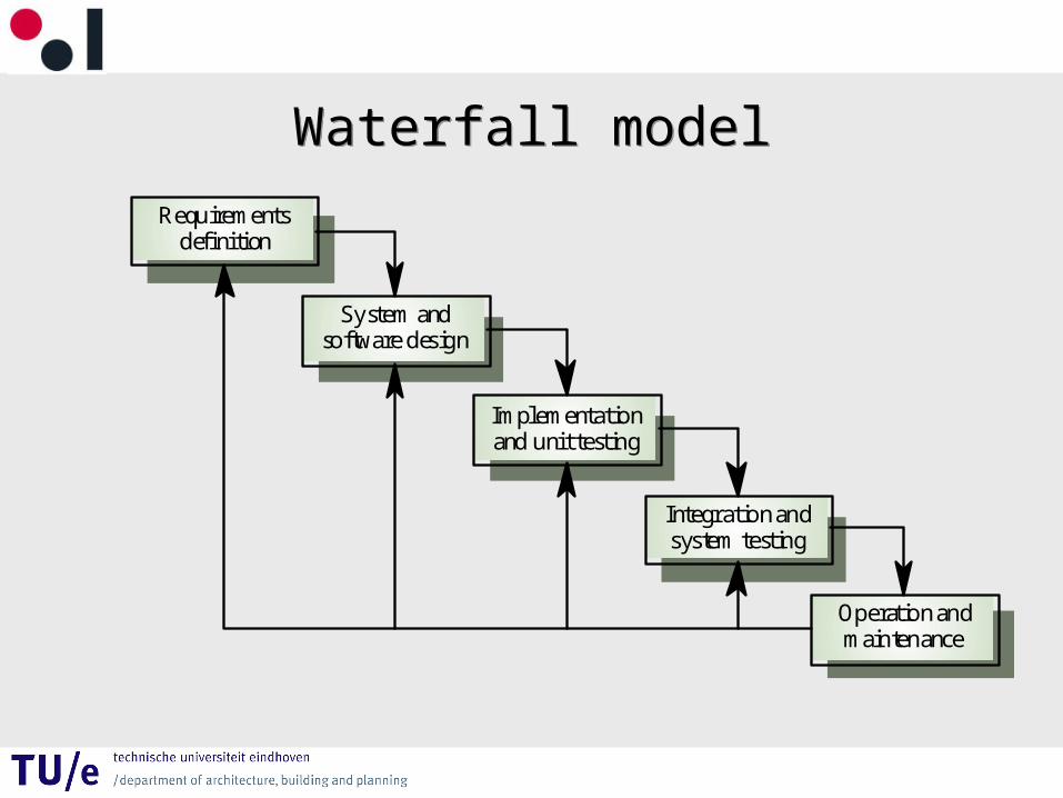
Waterfall modelWaterfall model
Requirementsdefinition
System andsoftware design
Implementationand unit testing
Integration andsystem testing
Operation andmaintenance
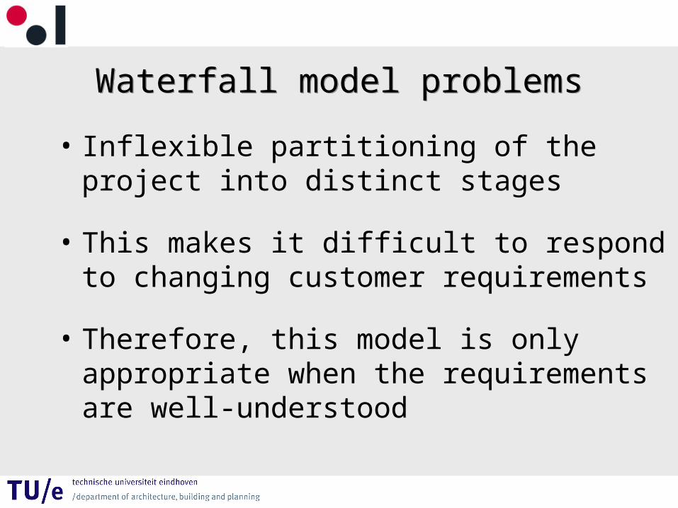
Waterfall model problemsWaterfall model problems
• Inflexible partitioning of the project into distinct stages
• This makes it difficult to respond to changing customer requirements
• Therefore, this model is only appropriate when the requirements are well-understood
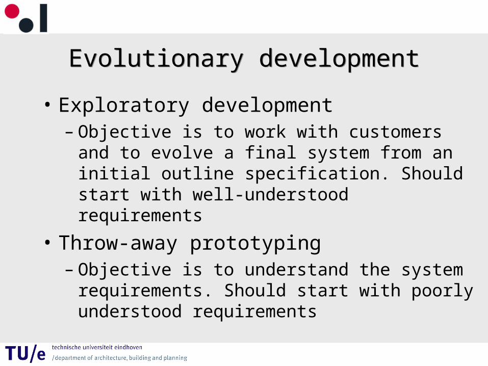
Evolutionary developmentEvolutionary development
• Exploratory development – Objective is to work with customers and to
evolve a final system from an initial outline specification. Should start with well-understood requirements
• Throw-away prototyping– Objective is to understand the system
requirements. Should start with poorly understood requirements
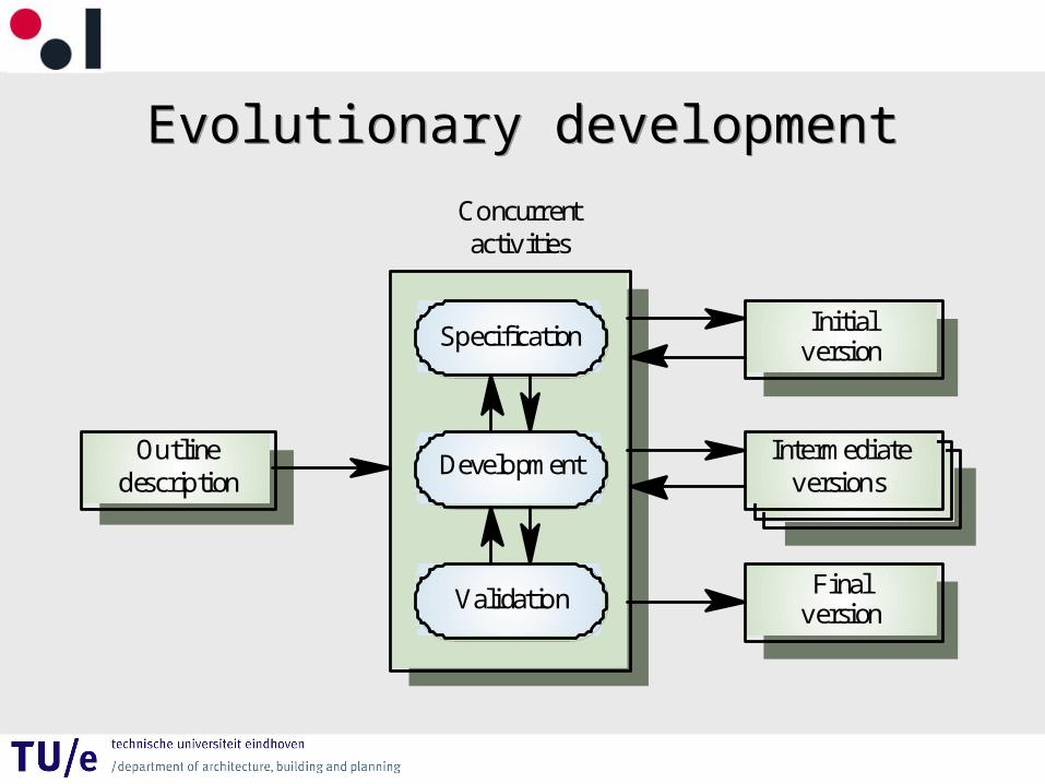
Evolutionary developmentEvolutionary development
ValidationFinal
version
DevelopmentIntermediate
versions
SpecificationInitial
version
Outlinedescription
Concurrentactivities
Evolutionary developmentEvolutionary development
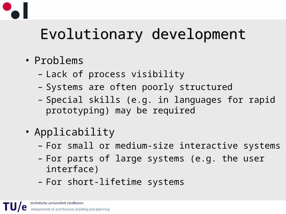
• Problems– Lack of process visibility– Systems are often poorly structured– Special skills (e.g. in languages for rapid prototyping)
may be required
• Applicability– For small or medium-size interactive systems– For parts of large systems (e.g. the user interface)– For short-lifetime systems
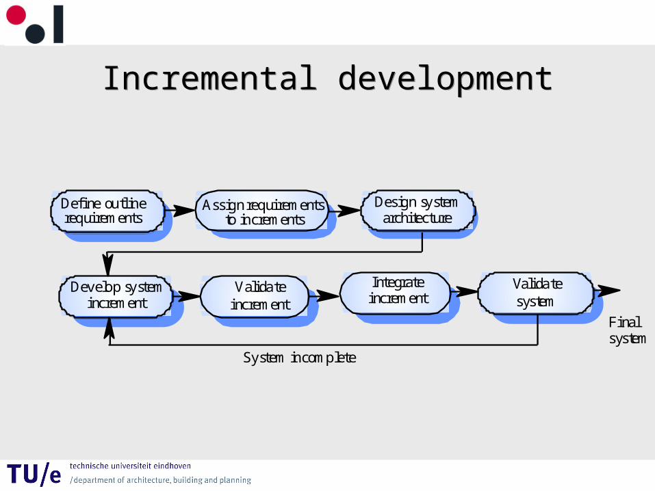
Incremental developmentIncremental development
Valida teincrement
Develop systemincrement
Design systemarchitecture
Integrateincrement
Valida tesystem
Define outline requirements
Assign requirements to increments
System incomplete
Finalsystem
Software RequirementsSoftware Requirements
• Descriptions and specifications of a system
Functional and non-functional requirementsFunctional and non-functional requirements
• Functional requirements• Statements of services the system should provide, how
the system should react to particular inputs and how the system should behave in particular situations.
• Non-functional requirements• constraints on the services or functions offered by the
system such as timing constraints, constraints on the development process, standards, etc.
Functional requirementsFunctional requirements
• Describe functionality or system services
• Depend on the type of software, expected users and the type of system where the software is used
• Functional user requirements may be high-level statements of what the system should do but functional system requirements should describe the system services in detail
Non-functional classificationsNon-functional classifications
• Product requirements• Requirements which specify that the delivered product must
behave in a particular way e.g. execution speed, reliability, etc.
• Organisational requirements• Requirements which are a consequence of organisational
policies and procedures e.g. process standards used, implementation requirements, etc.
• External requirements• Requirements which arise from factors which are external to
the system and its development process e.g. interoperability requirements, legislative requirements, etc.
Requirements and designRequirements and design
• In principle, requirements should state what the system should do and the design should describe how it does this
• In practice, requirements and design are inseparable– A system architecture may be designed to structure the
requirements– The system may inter-operate with other systems that
generate design requirements– The use of a specific design may be a domain
requirement
UML GeneralUML General
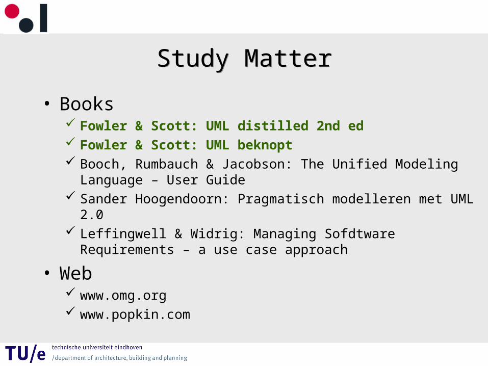
Study MatterStudy Matter
• Books Fowler & Scott: UML distilled 2nd ed Fowler & Scott: UML beknopt Booch, Rumbauch & Jacobson: The Unified Modeling Language –
User Guide Sander Hoogendoorn: Pragmatisch modelleren met UML 2.0 Leffingwell & Widrig: Managing Sofdtware Requirements – a use
case approach
• Web www.omg.org www.popkin.com
About UML 1 of 2About UML 1 of 2
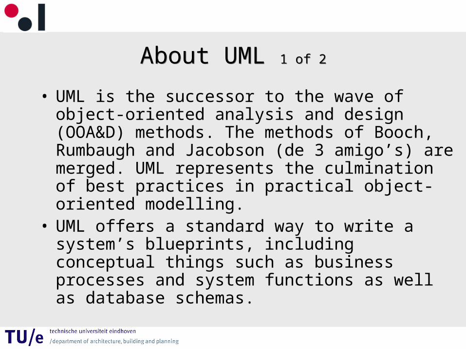
• UML is the successor to the wave of object-oriented analysis and design (OOA&D) methods. The methods of Booch, Rumbaugh and Jacobson (de 3 amigo’s) are merged. UML represents the culmination of best practices in practical object-oriented modelling.
• UML offers a standard way to write a system’s blueprints, including conceptual things such as business processes and system functions as well as database schemas.
About UML 2 of 2About UML 2 of 2
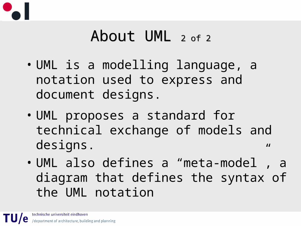
• UML is a modelling language, a notation used to express and document designs.
• UML proposes a standard for technical exchange of models and designs.
• UML also defines a “meta-model”, a diagram that defines the syntax of the UML notation
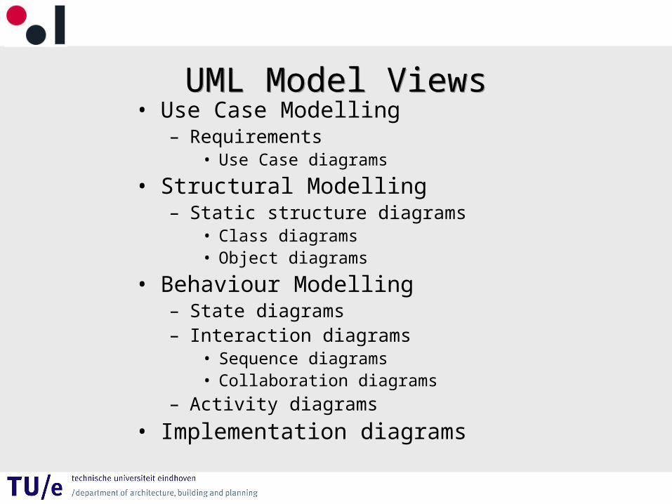
UML Model ViewsUML Model Views• Use Case Modelling
– Requirements • Use Case diagrams
• Structural Modelling– Static structure diagrams
• Class diagrams• Object diagrams
• Behaviour Modelling– State diagrams– Interaction diagrams
• Sequence diagrams• Collaboration diagrams
– Activity diagrams
• Implementation diagrams
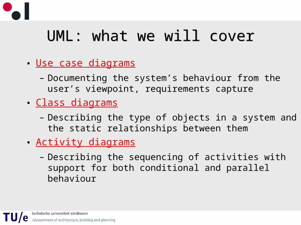
UML: what we will coverUML: what we will cover
• Use case diagrams– Documenting the system’s behaviour from the user’s
viewpoint, requirements capture
• Class diagrams– Describing the type of objects in a system and the static
relationships between them
• Activity diagrams– Describing the sequencing of activities with support for
both conditional and parallel behaviour
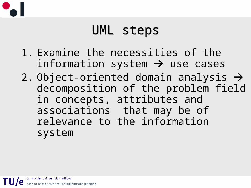
UML stepsUML steps
1. Examine the necessities of the information system use cases
2. Object-oriented domain analysis decomposition of the problem field in concepts, attributes and associations that may be of relevance to the information system
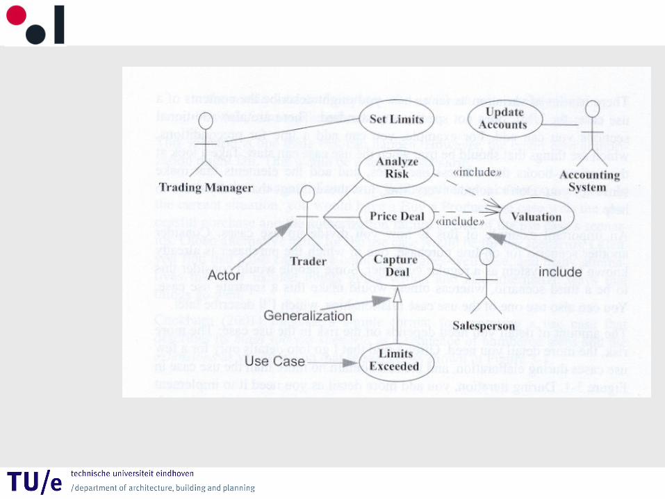
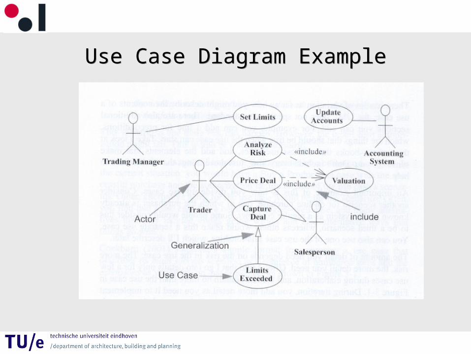
Use Case ModellingUse Case Modelling
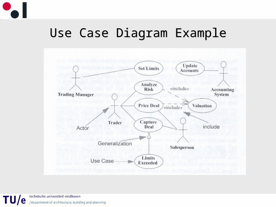
Use Case Diagram ExampleUse Case Diagram Example
Use Case ModellingUse Case Modelling
• A use case is a modelling technique used to describe what a new system should do or what an existing system already does.
• System developers and customers/end-users discuss a use case model. In an iterative process, this lead to a requirement specification on which all agree.
• A use case diagram describes the interaction between a set of use cases and the actors involved in these use cases.
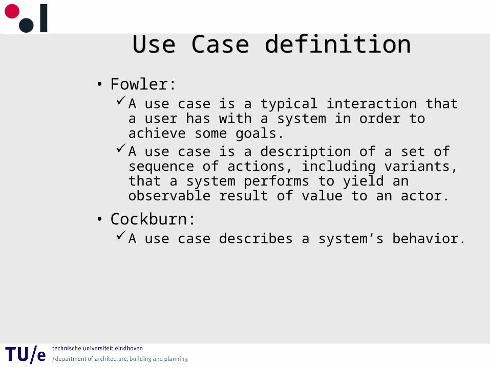
Use Case definitionUse Case definition
• Fowler:A use case is a typical interaction that a user has
with a system in order to achieve some goals.A use case is a description of a set of sequence
of actions, including variants, that a system performs to yield an observable result of value to an actor.
• Cockburn:A use case describes a system’s behavior.
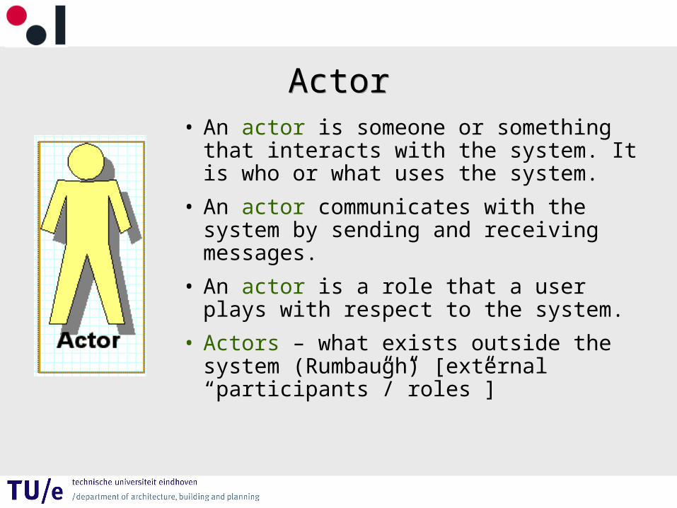
ActorActor• An actor is someone or something that
interacts with the system. It is who or what uses the system.
• An actor communicates with the system by sending and receiving messages.
• An actor is a role that a user plays with respect to the system.
• Actors – what exists outside the system (Rumbaugh) [external “participants”/”roles”]
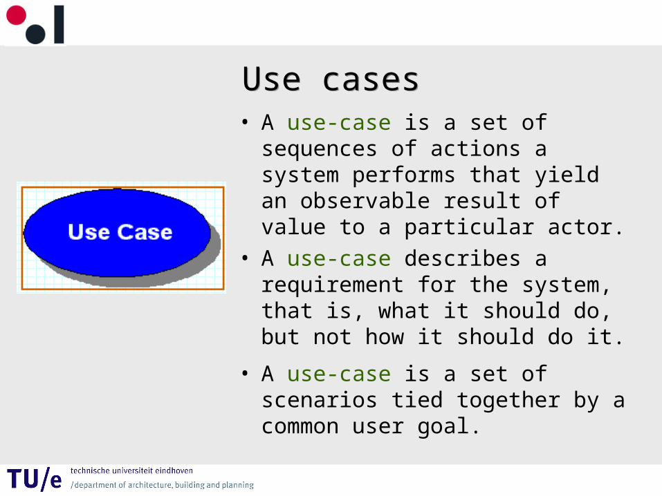
Use casesUse cases• A use-case is a set of sequences
of actions a system performs that yield an observable result of value to a particular actor.
• A use-case describes a requirement for the system, that is, what it should do, but not how it should do it.
• A use-case is a set of scenarios tied together by a common user goal.
Use Case Diagram ExampleUse Case Diagram Example
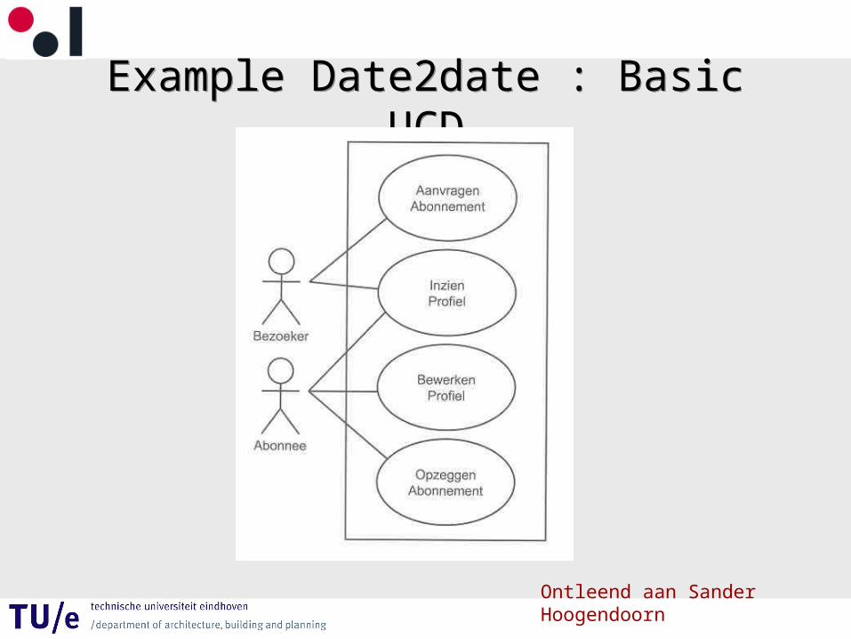
Example Date2date : Basic UCDExample Date2date : Basic UCD
Ontleend aan Sander Hoogendoorn
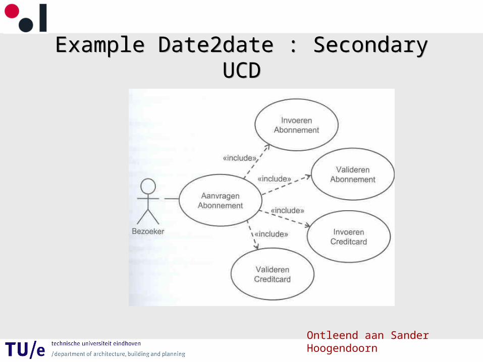
Example Date2date : Secondary UCDExample Date2date : Secondary UCD
Ontleend aan Sander Hoogendoorn
ScenarioScenario
A scenario is a sequence of steps describing an interaction between a user and a system.– A scenario is an instance of a use-case.– A scenario describes a possible interaction with
the system.
Scenario ExampleScenario Example
• Consider a Web-based on-line store, we might have a ‘Buy a Product’ scenario that would say this :The customer browses the catalogue and adds
desired items to the shopping basket. When the customer describes the shipping and credit card information and confirms the sale. The system checks the authorization on the credit card and confirms he sale both immediately and with a follow-up mail.
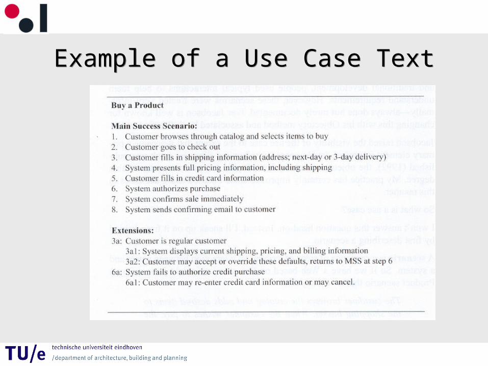
Example of a Use Case TextExample of a Use Case Text
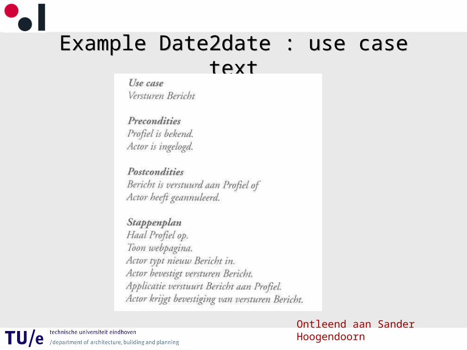
Example Date2date : use case textExample Date2date : use case text
Ontleend aan Sander Hoogendoorn
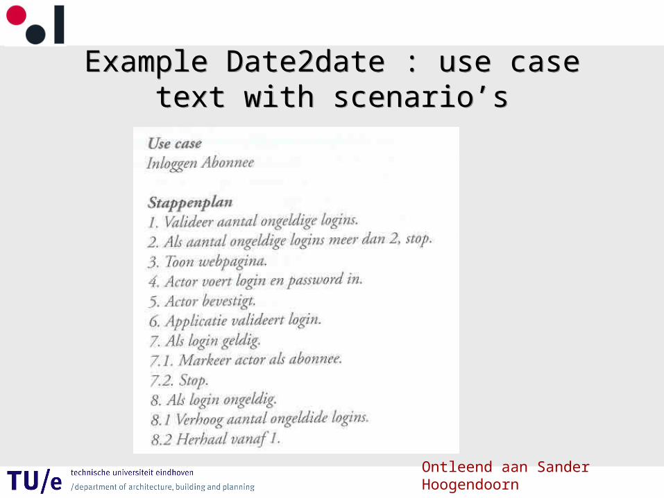
Example Date2date : use case text with scenario’s
Example Date2date : use case text with scenario’s
Ontleend aan Sander Hoogendoorn
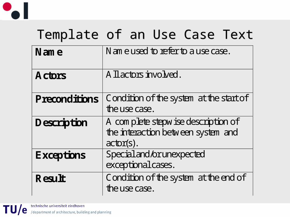
Template of an Use Case TextTemplate of an Use Case Text
Name Name used to refer to a use case.
Actors All actors involved.
Preconditions Condition of the system at the start of the use case.
Description A complete stepwise description of the interaction between system and actor(s).
Exceptions Special and/or unexpected exceptional cases.
Result Condition of the system at the end of the use case.
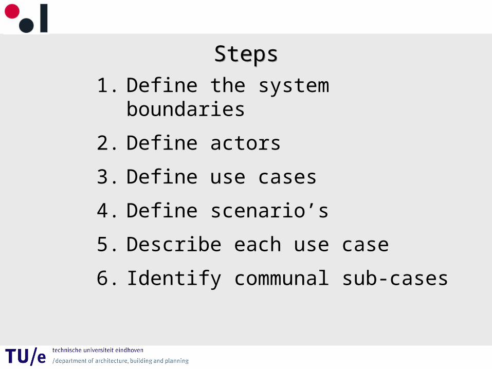
StepsSteps
1. Define the system boundaries
2. Define actors
3. Define use cases
4. Define scenario’s
5. Describe each use case
6. Identify communal sub-cases
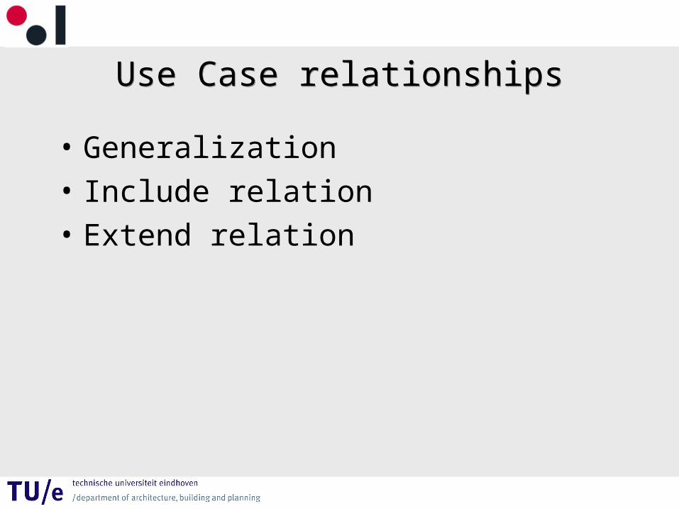
Use Case relationshipsUse Case relationships
• Generalization
• Include relation
• Extend relation
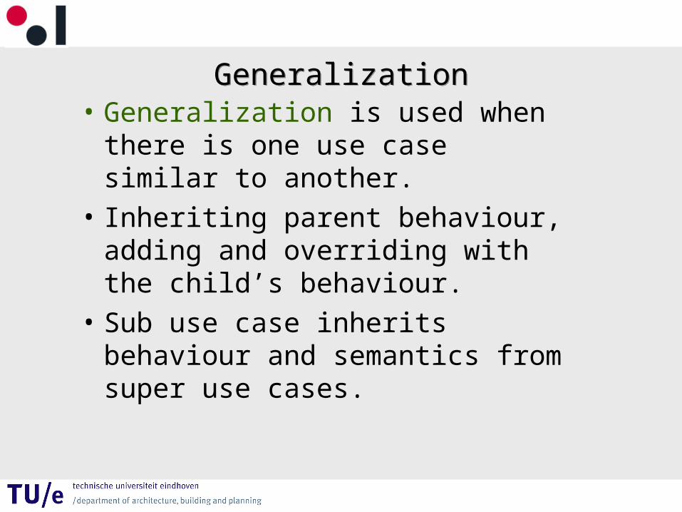
GeneralizationGeneralization• Generalization is used when there
is one use case similar to another.
• Inheriting parent behaviour, adding and overriding with the child’s behaviour.
• Sub use case inherits behaviour and semantics from super use cases.
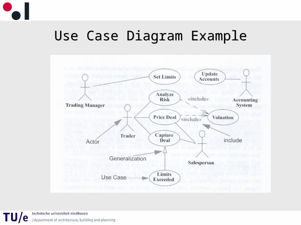
Use Case Diagram ExampleUse Case Diagram Example
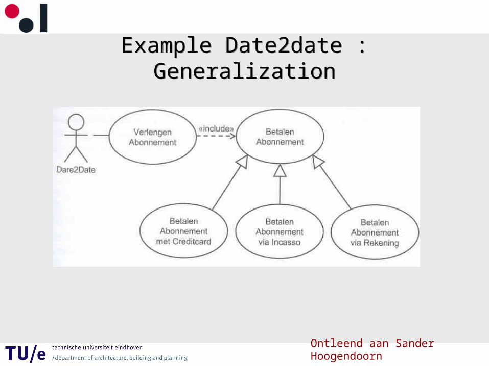
Example Date2date : GeneralizationExample Date2date : Generalization
Ontleend aan Sander Hoogendoorn
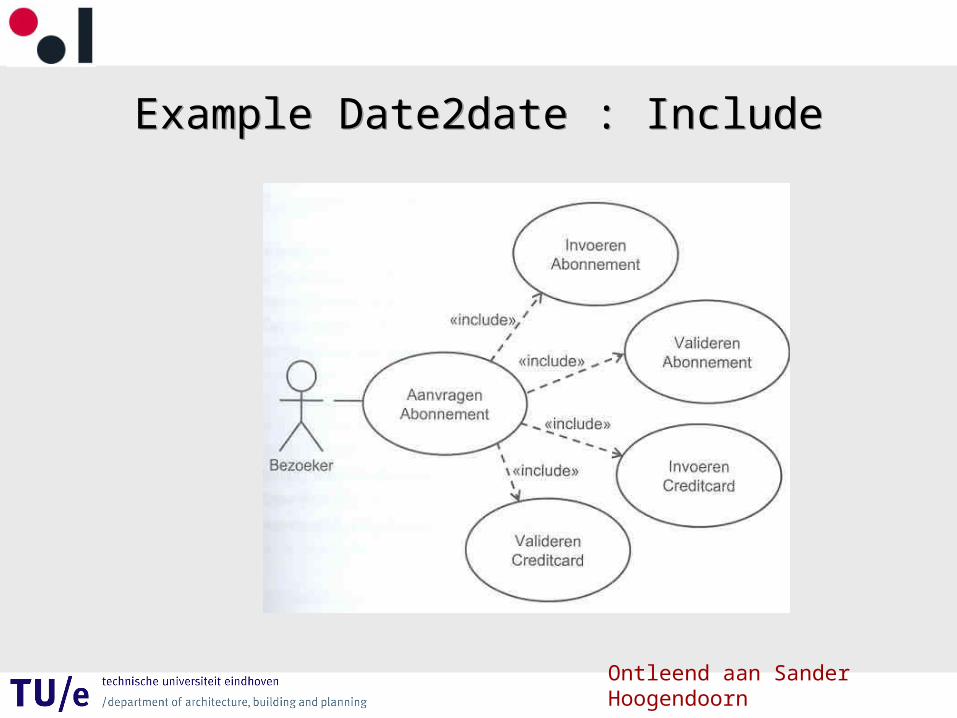
Example Date2date : IncludeExample Date2date : Include
Ontleend aan Sander Hoogendoorn
Include / UsesInclude / Uses
• Uses / Include : this relationship is used when there is a common chunck of behaviour across more than one use case.
• Base use case includes the functionality of included use case.

Use Case Diagram ExampleUse Case Diagram Example
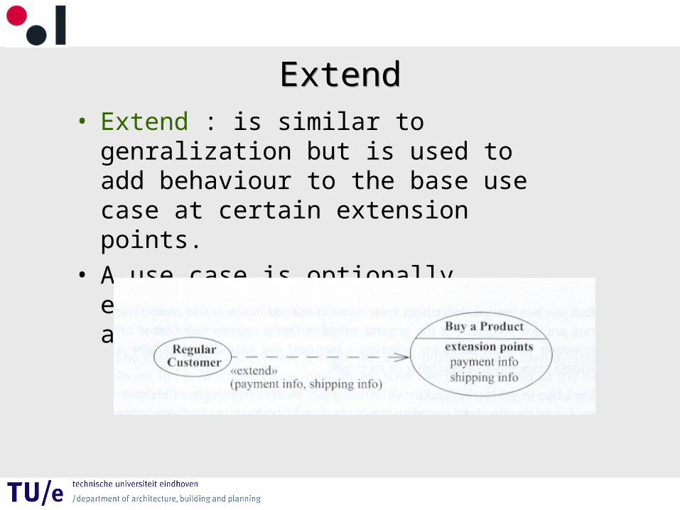
ExtendExtend• Extend : is similar to genralization but is
used to add behaviour to the base use case at certain extension points.
• A use case is optionally extended by functionality of another use case.
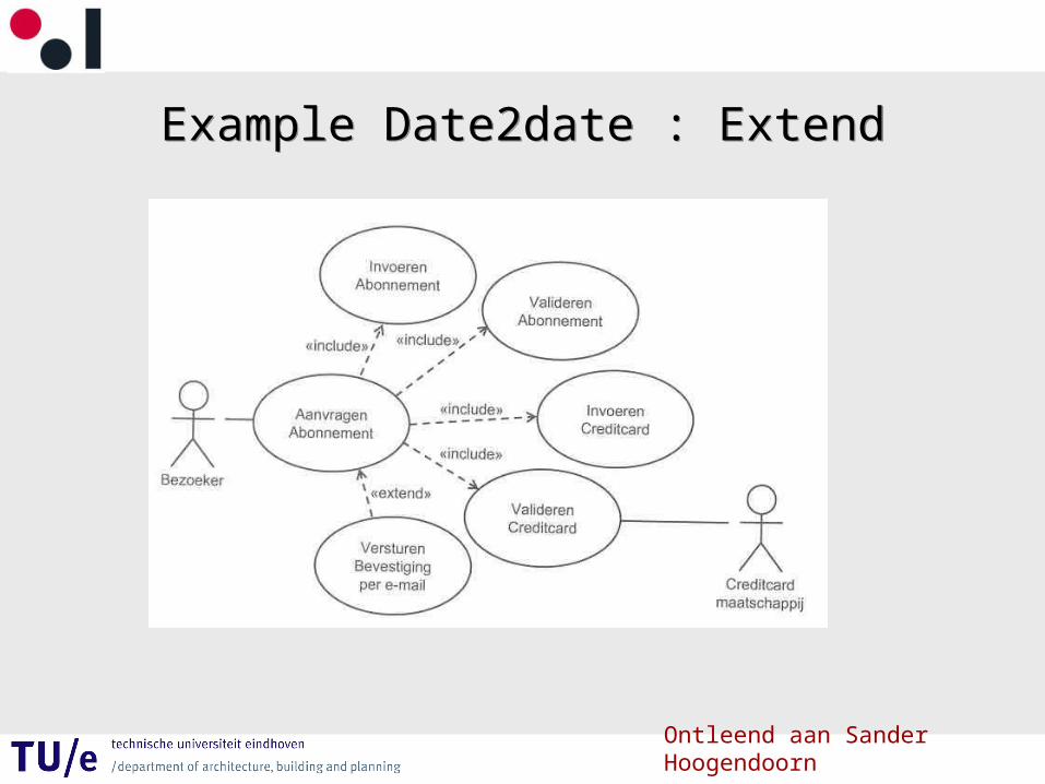
Example Date2date : ExtendExample Date2date : Extend
Ontleend aan Sander Hoogendoorn
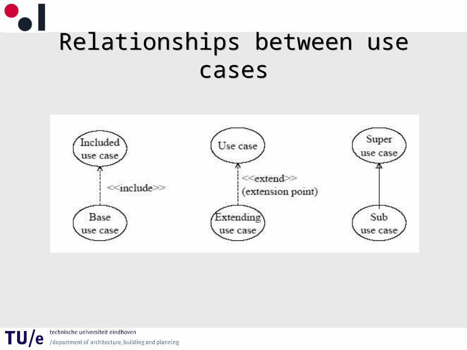
Relationships between use casesRelationships between use cases

Example Date2date : System boundary & Secondary actor
Example Date2date : System boundary & Secondary actor
Ontleend aan Sander Hoogendoorn
Short SummaryShort Summary
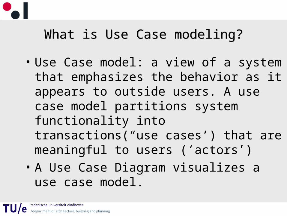
What is Use Case modeling?What is Use Case modeling?
• Use Case model: a view of a system that emphasizes the behavior as it appears to outside users. A use case model partitions system functionality into transactions(“use cases’) that are meaningful to users (‘actors’)
• A Use Case Diagram visualizes a use case model.
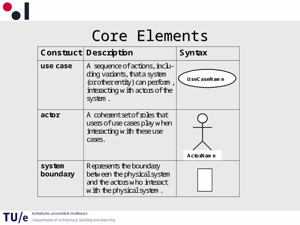
Core ElementsCore Elements
Construct Description Syntax
use case A sequence of actions, inclu-ding variants, that a system (or other entity) can perform, interacting with actors of the system.
actor A coherent set of roles that users of use cases play when interacting with these use cases.
system boundary
Represents the boundary between the physical system and the actors who interact with the physical system.
UseCaseName
ActorName
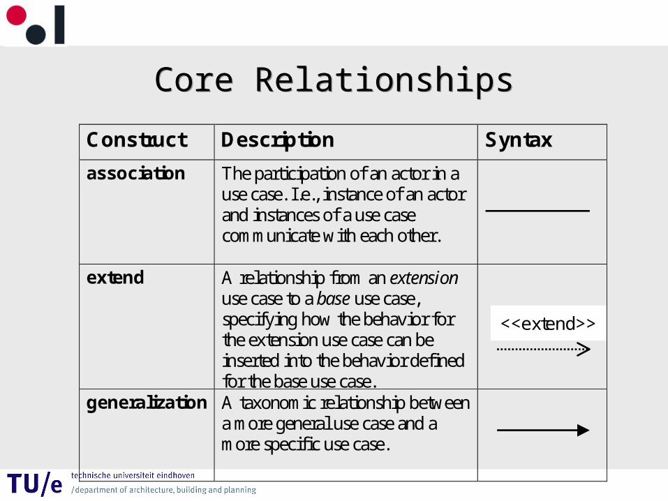
Core RelationshipsCore Relationships
Construct Description Syntax
association The participation of an actor in a use case. I.e., instance of an actor and instances of a use case communicate with each other.
extend A relationship from an extension use case to a base use case, specifying how the behavior for the extension use case can be inserted into the behavior defined for the base use case.
generalization A taxonomic relationship between a more general use case and a more specific use case.
<<extend>>
Core RelationshipsCore Relationships
Construct Description Syntax
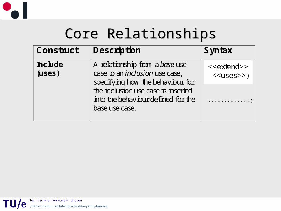
Include (uses)
A relationship from a base use case to an inclusion use case, specifying how the behaviour for the inclusion use case is inserted into the behaviour defined for the base use case.
<<extend>> <<uses>>)
Use Case Diagram : Example
Use Case Diagram : Example
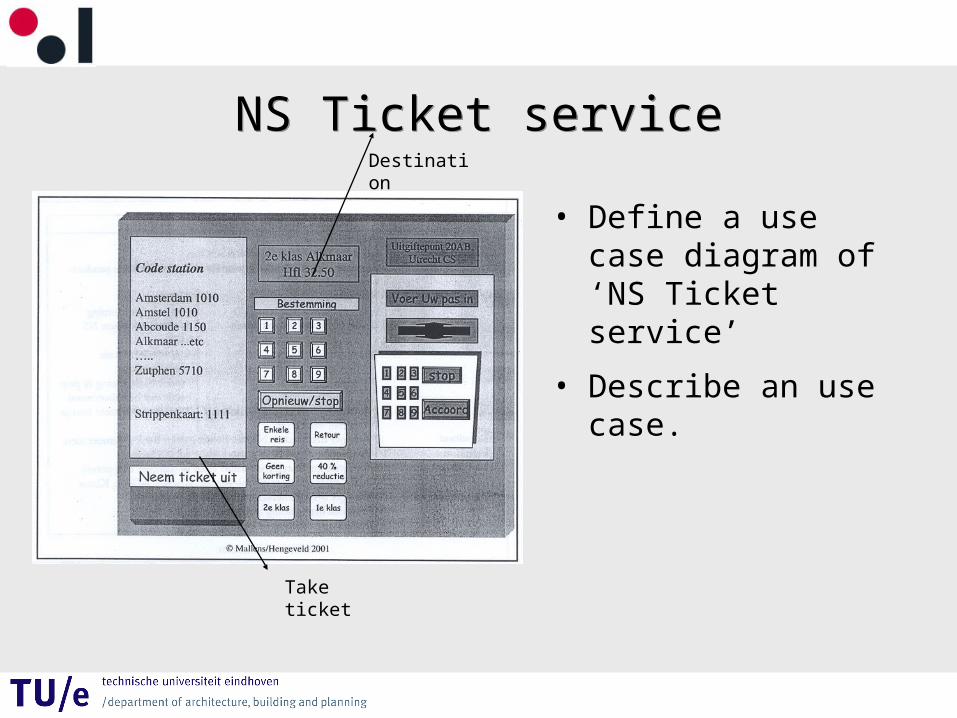
NS Ticket serviceNS Ticket service
• Define a use case diagram of ‘NS Ticket service’
• Describe an use case.
Take ticket
Destination
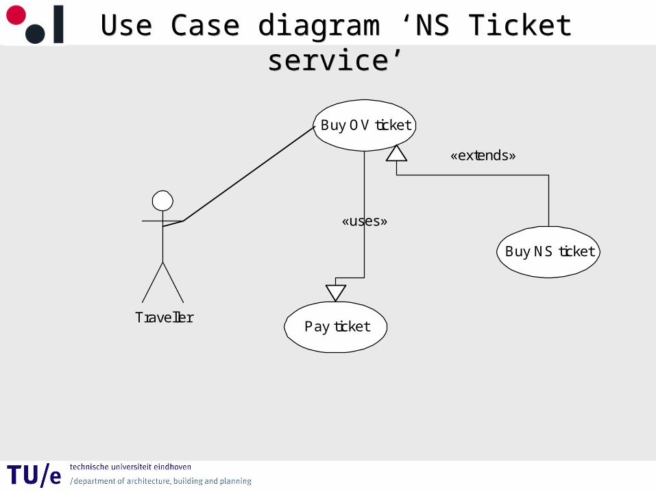
Use Case diagram ‘NS Ticket service’Use Case diagram ‘NS Ticket service’
Traveller
Buy OV ticket
Buy NS ticket
Pay ticket
«extends»
«uses»
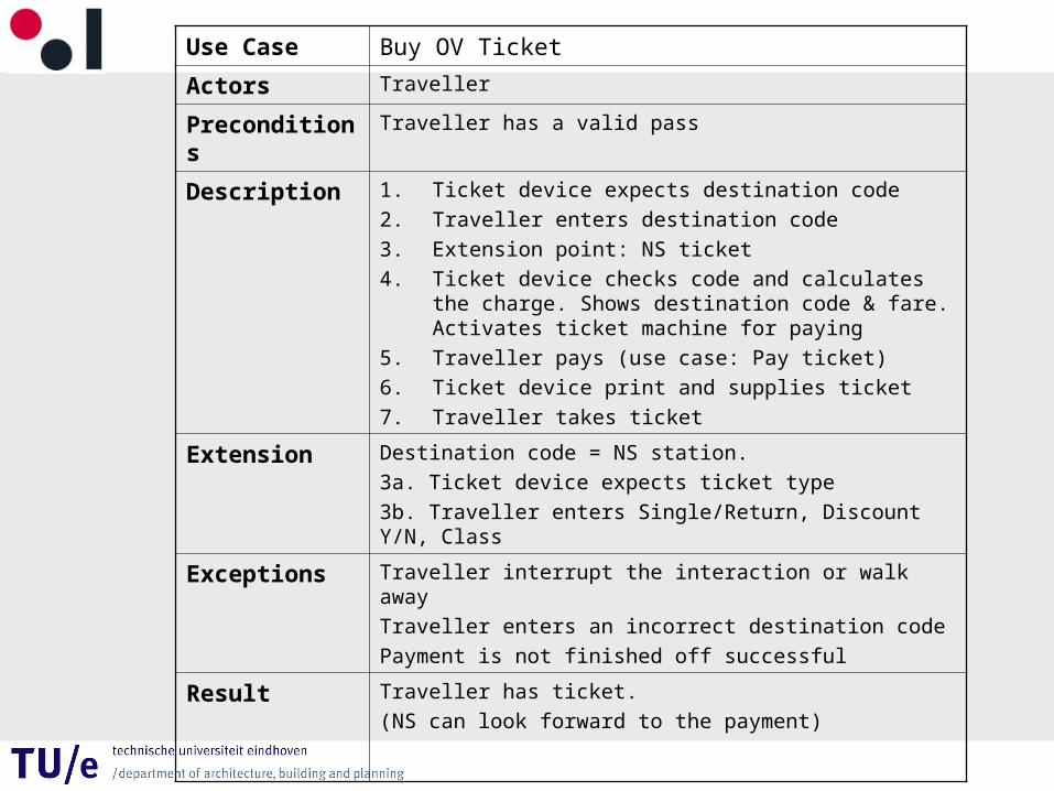
Use Case Buy OV Ticket
Actors Traveller
Preconditions Traveller has a valid pass
Description 1. Ticket device expects destination code
2. Traveller enters destination code
3. Extension point: NS ticket
4. Ticket device checks code and calculates the charge. Shows destination code & fare. Activates ticket machine for paying
5. Traveller pays (use case: Pay ticket)
6. Ticket device print and supplies ticket
7. Traveller takes ticket
Extension Destination code = NS station.
3a. Ticket device expects ticket type
3b. Traveller enters Single/Return, Discount Y/N, Class
Exceptions Traveller interrupt the interaction or walk away
Traveller enters an incorrect destination code
Payment is not finished off successful
Result Traveller has ticket.
(NS can look forward to the payment)
Exercise UCDExercise UCD
Starting point is the MKW casus
• Make a Use Case Diagram of the MKW system and describe the use cases with an use case text.