boundary curvature guided shape-programming kirigami sheets
TRANSCRIPT

1
Boundary curvature guided shape-programming kirigami sheets
Yaoye Hong1, Yinding Chi1, Yanbin Li1, Yong Zhu1, Jie Yin1,*
aDepartment of Mechanical and Aerospace Engineering, North Carolina State University,
Raleigh, NC 27695, USA.
*To whom correspondence may be addressed. Email: [email protected]
Abstract
Kirigami, an ancient paper cutting art, offers a promising strategy for 2D-to-3D shape morphing
through cut-guided deformation. Existing kirigami designs for target 3D curved shapes rely on
intricate cut patterns in thin sheets, making the inverse design challenging. Motivated by the
Gauss-Bonnet theorem that correlates the geodesic curvature along the boundary with the
topological Gaussian curvature, here, we exploit programming the curvature of cut boundaries
rather than complex cut patterns in kirigami sheets for target 3D curved topologies through both
forward and inverse designs. Such a new strategy largely simplifies the inverse design. We
demonstrate the achievement of varieties of dynamic 3D shape shifting under both mechanical
stretching and remote magnetic actuation, and its potential application as an untethered predator-
like kirigami soft robot. This study opens a new avenue to encode boundary curvatures for shape-
programing materials with potential applications in shape-morphing structures, soft robots, and
multifunctional devices.

2
INTRODUCTION
Designing shape-programming materials from 2D thin sheets to 3D shapes has attracted broad and
increasing interest in the past decades due to their novel materials properties imparted by
geometrical shapes (1). Programmable shape shifting in various non-active and stimuli-responsive
materials was realized at all scales utilizing folding, bending, and buckling (2). These shape-
programmable materials are attractive for broad applications in programmable machines and
robots (3, 4), functional biomedical devices (5), and four-dimensional (4D) printing (6, 7).
Kirigami, the ancient art of paper cutting, has recently emerged as a new promising approach for
creating shape morphing structures and materials (8, 9). Cuts divide the original continuous thin
sheets into discretized cut units but without sacrificing the structural integrity. Compared to
continuous thin sheets, kirigami sheet enables more freedom and flexibility in shape shifting
through local or global deformation between cut units (10). Starting from a thin sheet with
patterned cuts, it can morph into varieties of 3D pop-up structures and surface topologies (8, 9) via
rigid rotation mechanism (11) and/or out-of-plane buckling (12). The cuts impart new properties
such as auxeticity (13, 14), stretchability (15-20), conformability (16), multistability (21), and
optical chirality (22), which have found broad applications in mechanical metamaterials (14, 20,
23), stretchable devices (16-18, 24, 25), 3D mechanical self-assembly (26), tunable adhesion (27),
and soft machines (10, 28, 29). The actuation of 2D-to-3D shape shifting can be achieved in both
non-active and active materials in response to mechanical strains (13, 14, 16), environmental
temperature (10, 30, 31), light (29), and magnetic field (17, 20).
Specifically, starting from a kirigami sheet or shell, 3D shapes with intrinsic curvature can be
generated by utilizing non-uniform patterning and tessellation of polygon cut units through
mechanical strains (32, 33) or pneumatic pressurization (34). The local heterogeneous deformation
among non-periodic tessellated cut units induces global out-of-plane buckling of the 2D kirigami
sheets, thus, resulting in the formation of different 3D curved shapes (32, 33). However, it often
requires programming intricate cut patterns and arrangements of non-periodic cut units, making
the inverse design and optimization for target 3D shapes complicated and challenging (33, 34).
Theoretically, the curvature of a boundary can be harnessed to tune 3D curved shapes based on
the Gauss-Bonnet theorem in differential geometry (35), which correlates the topological Gaussian
curvature and the geodesic curvature along the boundary (i.e., the projection of boundary

3
curvature). Motivated by this theorem, here, we propose a new and simple strategy of utilizing the
boundary curvature of cut edges rather than complex cut patterns to program 3D curved shapes
through both forward and inverse designs. Unlike previous networked polygon cut units (14, 16,
32-34), our kirigami sheet is composed of parallel discrete ribbons enclosed by continuous
boundaries (Fig. 1 A) through simple patterning of parallel cuts. We demonstrated that simply
stretching the kirigami sheet with prescribed curved cut boundaries could generate varieties of
well-predicted 3D curved shapes with positive, negative, and zero Gaussian curvatures and their
combinations. The formed 3D shapes could be further reconfigured into other distinct
configurations via bistability. We proposed a straightforward inverse design strategy for target 3D
curved shapes by utilizing the geodesic feature of discrete ribbons. Finally, we demonstrated
remote magnetic actuation to expand the shape-morphing capability and its proof-of-concept
application in untethered soft robotics.
RESULTS
Manipulating 2D boundary curvatures for 3D curved topologies
The classical Gauss-Bonnet theorem (35) correlates the boundary curvature with the global
topological Gaussian curvature K. Motivated by the theorem, as shown in Fig. 1, we start by
designing the 2D precursors of kirigami sheets with different boundary curvatures kbo to exploit
its effects on the Gaussian curvature of their 3D deployed shapes, where kbo is set to be positive
(circular boundary in Fig. 1 A, i), zero (rectangular boundary in Fig. 1 B, i), and negative
(biconcave circular boundary in Fig. 1 C, i), respectively. We use the polyethylene terephthalate
(PET) sheet with Young’s modulus of 3.5 GPa, Poisson’s ratio of 0.38, and thickness of 127 μm
to fabricate the kirigami sheets using laser cutting (Supplementary Materials, Section S1). The thin
sheets are cut into a number of discrete parallel thin ribbons enclosed by continuous boundary
ribbon (ribbon width of 1.5 mm in Fig. 1 A and B and 0.75 mm in Fig. 1 C).
Fig. 1 A, ii - C, ii show that stretching the 2D precursors leads to distinct spheroidal, cylindrical,
and saddle shapes with positive, zero, and negative Gaussian curvature K, respectively. Upon
stretching, the boundary ribbon starts bending and compresses the enclosed discrete ribbons to
induce their out-of-plane buckling. Thus, it renders a 3D pop-up topology. It should note that
distinct from kirigami sheets composed of networked polygon cut units in previous studies (14, 16,

4
32-34), the simple design of parallel cuts in this work endows several unique characteristics: (1) It
allows the sheet to be stretched along the direction perpendicular to the cuts via buckling of discrete
ribbons. (2) Each bended discrete ribbon is bistable so that it could be tuned to either pop up or
pop down for potential reconfiguration locally or globally (Fig. S1). (3) Parallel cuts make each
discrete ribbon a geodesic curve of the morphed topology (Supplementary Materials, Section S2),
facilitating inverse design as discussed later.
The observed 3D curved shapes can be qualitatively explained by the Gauss-Bonnet theorem.
Mathematically, for the morphed 3D pop-up topology, the theorem can be simplified as
[1]
where the constant C remains unchanged during shape shifting, and is the geodesic
curvature along the boundary ribbon (35), i.e., the projection of the deformed boundary curvature
kb with being the projection angle (Supplementary Materials, Section S2). Thus, for 2D kirigami
precursors with positive boundary curvature, i.e., kbo > 0, as the applied strain increases, kgb
decreases, resulting in a positive Gaussian curvature according to Eq. (1), i.e., K > 0 (see details
in Supplementary Materials, Section S2), which is consistent with the observed spheroidal shape
in Fig. 1 A, ii . For the case of kbo = 0, during the deformation, kgb remains zero, leading to a
cylindrical shape with K = 0 as shown in Fig. 1 B, ii. Similarly, for the case of kbo < 0 , kgb increases
with the increasing applied strain. Thus, we have K < 0 in the observed saddle shape (Fig. 1 C, ii).
Analytical Modeling and Simulation on 3D Shape Shifting
To quantify shape shifting of the kirigami structures with the applied strain, we combine both
analytical modeling and finite element method (FEM) simulation to predict their topology changes
(see details in Supplementary Materials, Section S1). The deformation of the kirigami structures
is dominated by bending of the discrete ribbons, where the elastic strain energy in the boundary
ribbon is negligible due to its small width (Supplementary Materials, Section S3). Thus, all the
discrete ribbons share similar deformed elastica shapes (36, 37). The deformed 3D shape at an
applied strain ε can be described by , where and
denote the normalized arc length coordinate of the boundary and the discrete ribbon as illustrated
gbKdA k ds CW ¶W
+ =ò ò
singb bk k j=
j
( , ) ( ( , ), ( , ), ( , ))s b d b d b d b dr s s x s s y s s z s s=! bs ds
5
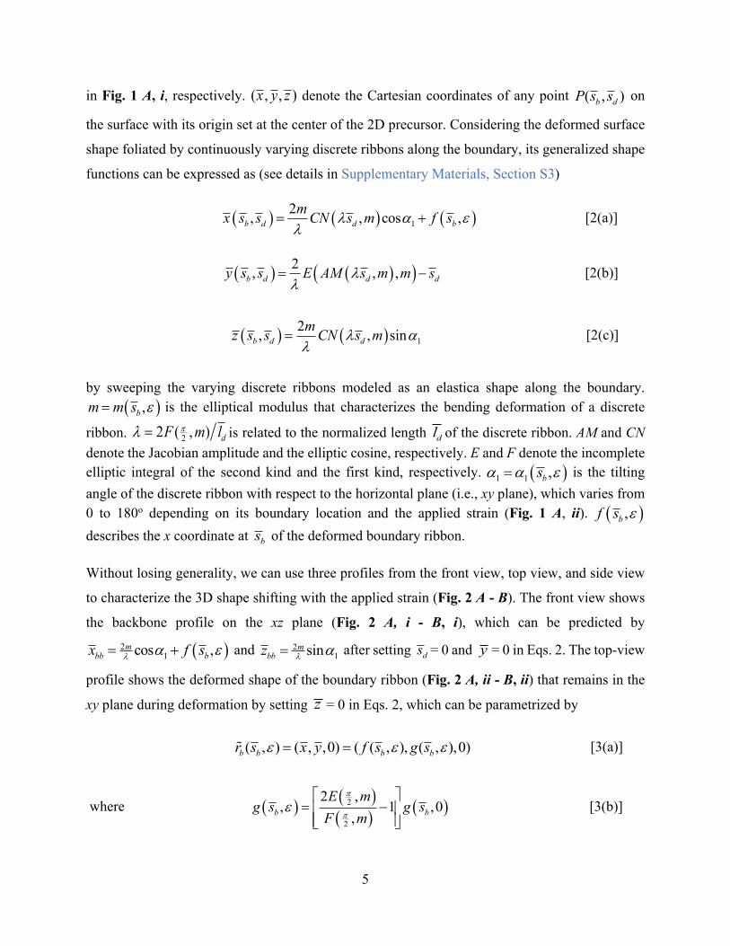
in Fig. 1 A, i, respectively. denote the Cartesian coordinates of any point on
the surface with its origin set at the center of the 2D precursor. Considering the deformed surface
shape foliated by continuously varying discrete ribbons along the boundary, its generalized shape
functions can be expressed as (see details in Supplementary Materials, Section S3)
[2(a)]
[2(b)]
[2(c)]
by sweeping the varying discrete ribbons modeled as an elastica shape along the boundary. is the elliptical modulus that characterizes the bending deformation of a discrete
ribbon. is related to the normalized length of the discrete ribbon. AM and CN denote the Jacobian amplitude and the elliptic cosine, respectively. E and F denote the incomplete elliptic integral of the second kind and the first kind, respectively. is the tilting angle of the discrete ribbon with respect to the horizontal plane (i.e., xy plane), which varies from 0 to 180o depending on its boundary location and the applied strain (Fig. 1 A, ii). describes the x coordinate at of the deformed boundary ribbon.
Without losing generality, we can use three profiles from the front view, top view, and side view
to characterize the 3D shape shifting with the applied strain (Fig. 2 A - B). The front view shows
the backbone profile on the xz plane (Fig. 2 A, i - B, i), which can be predicted by
and after setting = 0 and = 0 in Eqs. 2. The top-view
profile shows the deformed shape of the boundary ribbon (Fig. 2 A, ii - B, ii) that remains in the
xy plane during deformation by setting = 0 in Eqs. 2, which can be parametrized by
[3(a)]
where [3(b)]
( , , )x y z ( , )b dP s s
( ) ( ) ( )12, , cos ,b d d bmx s s CN s m f sl a el
= +
( ) ( )( )2, , ,b d d dy s s E AM s m m sll
= -
( ) ( ) 12, , sinb d dmz s s CN s ml al
=
( ),bm m s e=
22 ( , ) dF m lpl = dl
( )1 1 ,bsa a e=
( ),bf s e
bs
( )21cos ,m
bb bx f sl a e= + 21sinm
bbz l a= ds y
z
( , ) ( , ,0) ( ( , ), ( , ),0)b b b br s x y f s g se e e= =!
( ) ( )( ) ( )2
2
2 ,, 1 ,0
,b b
E mg s g s
F m
p
pe
é ù= -ê úê úë û

6
describes the y coordinate at of the deformed boundary ribbon at the strain of ε. Eq. 3(b)
describes the relationship between m and ε. Thus, combining Eqs. 2 and Eq. 3(b) will determine
the unknown parameters of , , , and m to predict the deformed 3D shapes with the applied
strain. The side view shows the projection of similar elastica shapes of discrete ribbons onto the
yz plane (Fig. 2 A, iii - B, iii), which depends on m and the tilting angle of the longest discrete
ribbon. Its deformed elastica shape can be expressed by and
, where the length of the discrete ribbons is assumed to be unchanged during
deformation.
Next, we apply both the generalized analytical model and FEM simulation to analyze the 3D shape
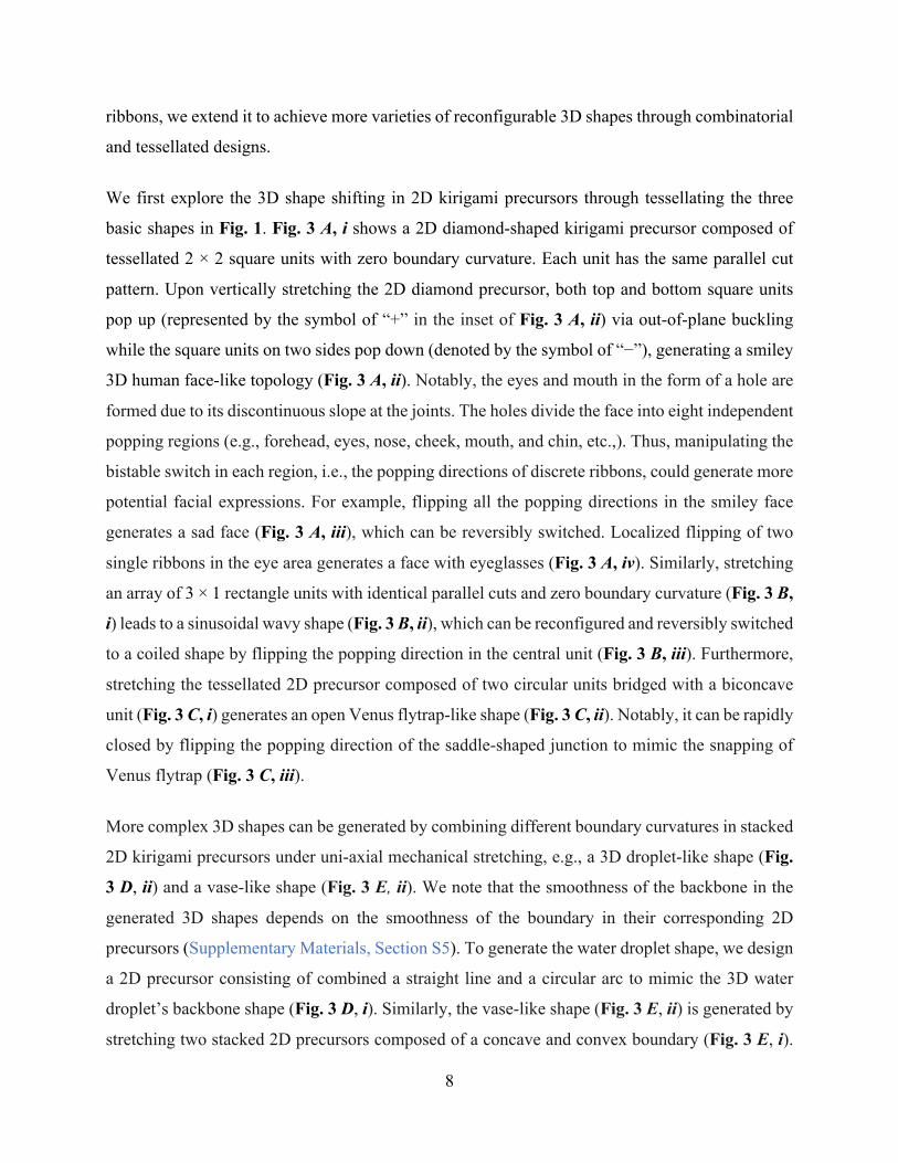
shifting in the specific examples shown in Fig. 1. Fig. 2 A, i-iii theoretically predict the variation
of the three profiled shapes with the applied strain ε during the formation of a spheroidal shape.
As ε increases from 0 to 0.4, top-view profiles show that the circular boundary gradually deforms
into an elliptical shape (Fig. 2 A, ii), where we have and
( ) in the model (Supplementary Materials, Section
S3). and denote the radial and tangential displacement of the boundary ribbon
(38), respectively. Correspondingly, the compressed discrete ribbons deform into an elastica shape
(side view in Fig. 2 A, iii). The backbone expands and shows an elliptical profile (front view in
Fig. 2 A, i, Supplementary Materials, Section S2). As shown in Fig. 2 A, i-iii, the superposition of
the three theoretically predicted front-view, top-view, and side-view profiles (highlighted in purple
color) with images retrieved from the experimental observation at ε = 0.3 shows an excellent
agreement. Similarly, the corresponding FEM simulated deformed 3D shape shows an excellent
overlapping with the experiment (Fig. 2 A, iv).
Fig. 2 B, i-iii show the predicted shape change during the formation of a saddle shape. In contrast
to simultaneous buckling in generating the spheroidal and cylindrical shapes (Supplementary
Video S1-S2 and Fig. S6), we observe a sequential buckling during the formation of the saddle
shape in experiments. The discrete ribbons near two stretching ends pop up first, followed by the
ribbons in the center when beyond a critical strain εc (Fig. S7). Such a sequential shape shifting is
well captured by both the analytical model and FEM simulation (Supplementary Video S3). As
bs
x y z
2 ( ( , ), )d d dy E AM s m m sl l= -
2 ( , )md dz CN s ml l=
( ) ( ), 1 sin cosb b bf s w s v se = - +
( ), (1 )cos sinb b bg s w s v se = - - 2 2[ , ]bs p pÎ -
( ),bw s e ( ),bv s e

7
predicted by the model, Fig. 2 B, ii shows that at the critical strain εc ≈ 1.42, the initial concave
boundary ribbon deforms into a straight line and remains straight upon further deformation, where
we have and with in the model
(Supplementary Materials, Section S3). Correspondingly, the backbone profile (Fig. 2 B, i) transits
from an initial sharp V shape to a smooth concave shape, which exhibits a sudden jump of the
displacement along z-axis when the applied strain is slightly beyond εc. Further stretching results
in the formation of the saddle shape with a concave backbone, which is consistent with both
experiments (Fig. 2 B, i-iii) and FEM simulation results (Fig. 2 B, iv).
Based on the validated theoretical model, we further establish the general quantitative correlation
between the boundary curvature kbo of 2D kirigami precursors and the Gaussian curvature K of
their popped 3D topologies at a given applied strain (see details in Supplementary Materials,
Section S4). Fig. 2 C and D show the theoretically predicted 3D maps of the normalized Gaussian
curvature at the center point C as a function of both normalized boundary curvature (see
illustration of tuning different kbo in insets of Fig. 2 C and D) and applied strain . It shows that
for 2D kirigami precursors with either positive (Fig. 2C) or negative boundary curvature (Fig. 2D),
generally, the absolute value of increases with an increasing strain and . Note that
for the formed saddle shapes, we have = 0 before reaching the critical strain εc. At the onset of
εc, suddenly decreases due to a dramatic increase in the boundary curvature. Beyond εc,
barely changes because the boundary ribbon remains straight (Fig. 2D). Interestingly, Fig. 2 E
shows that theoretically, the normalized variation of Gaussian curvature increases
approximately linearly with the normalized variation of boundary curvature (slope ≈ 1)
(Supplementary Materials, Section S4), which is consistent with the experimental measurements.
is the maximum Gaussian curvature at the center point. Specifically, this near-linear
relationship holds regardless of the initial boundary curvature of a 2D kirigami precursor.
Combinatorial designs for more complex 3D shapes
Next, equipped with the knowledge of the correlation between the boundary curvature and the
deformed 3D shapes, as well as the bistable feature (popping up or down in Fig. S1) in the discrete
( ),b bf s se = ( ) 2, 1.46 ( 0.32)bg s e e= - - [ 1.32,1.32]bs Î -
K bok
e
| |K e | |bok
K
K K
max| |K KD
| |b bok kD
maxK
8
ribbons, we extend it to achieve more varieties of reconfigurable 3D shapes through combinatorial
and tessellated designs.
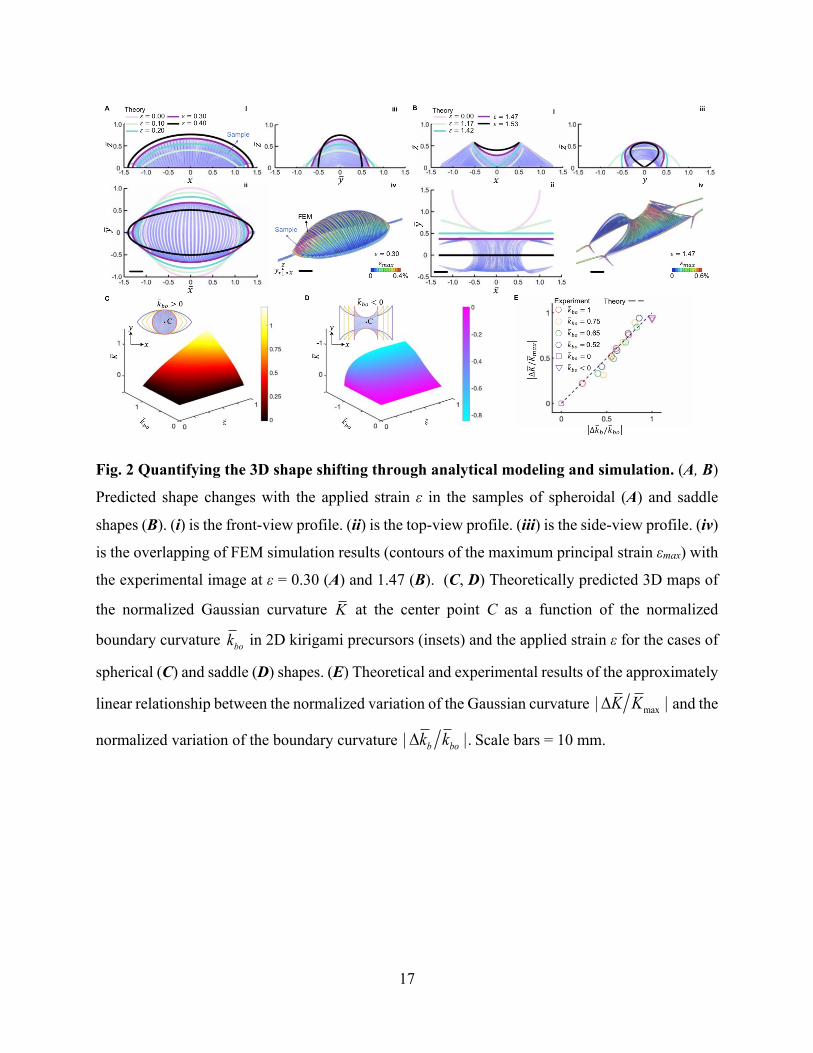
We first explore the 3D shape shifting in 2D kirigami precursors through tessellating the three
basic shapes in Fig. 1. Fig. 3 A, i shows a 2D diamond-shaped kirigami precursor composed of
tessellated 2 × 2 square units with zero boundary curvature. Each unit has the same parallel cut
pattern. Upon vertically stretching the 2D diamond precursor, both top and bottom square units
pop up (represented by the symbol of “+” in the inset of Fig. 3 A, ii) via out-of-plane buckling
while the square units on two sides pop down (denoted by the symbol of “−”), generating a smiley
3D human face-like topology (Fig. 3 A, ii). Notably, the eyes and mouth in the form of a hole are
formed due to its discontinuous slope at the joints. The holes divide the face into eight independent
popping regions (e.g., forehead, eyes, nose, cheek, mouth, and chin, etc.,). Thus, manipulating the
bistable switch in each region, i.e., the popping directions of discrete ribbons, could generate more
potential facial expressions. For example, flipping all the popping directions in the smiley face
generates a sad face (Fig. 3 A, iii), which can be reversibly switched. Localized flipping of two
single ribbons in the eye area generates a face with eyeglasses (Fig. 3 A, iv). Similarly, stretching
an array of 3 × 1 rectangle units with identical parallel cuts and zero boundary curvature (Fig. 3 B,
i) leads to a sinusoidal wavy shape (Fig. 3 B, ii), which can be reconfigured and reversibly switched
to a coiled shape by flipping the popping direction in the central unit (Fig. 3 B, iii). Furthermore,
stretching the tessellated 2D precursor composed of two circular units bridged with a biconcave
unit (Fig. 3 C, i) generates an open Venus flytrap-like shape (Fig. 3 C, ii). Notably, it can be rapidly
closed by flipping the popping direction of the saddle-shaped junction to mimic the snapping of
Venus flytrap (Fig. 3 C, iii).
More complex 3D shapes can be generated by combining different boundary curvatures in stacked
2D kirigami precursors under uni-axial mechanical stretching, e.g., a 3D droplet-like shape (Fig.
3 D, ii) and a vase-like shape (Fig. 3 E, ii). We note that the smoothness of the backbone in the
generated 3D shapes depends on the smoothness of the boundary in their corresponding 2D
precursors (Supplementary Materials, Section S5). To generate the water droplet shape, we design
a 2D precursor consisting of combined a straight line and a circular arc to mimic the 3D water
droplet’s backbone shape (Fig. 3 D, i). Similarly, the vase-like shape (Fig. 3 E, ii) is generated by
stretching two stacked 2D precursors composed of a concave and convex boundary (Fig. 3 E, i).

9
Furthermore, stretching multiple layers of similar semi-circular 2D precursors (Fig. 3 F, i)
generates a flower-like shape with multilayer pedals (Fig. 3 F, ii).
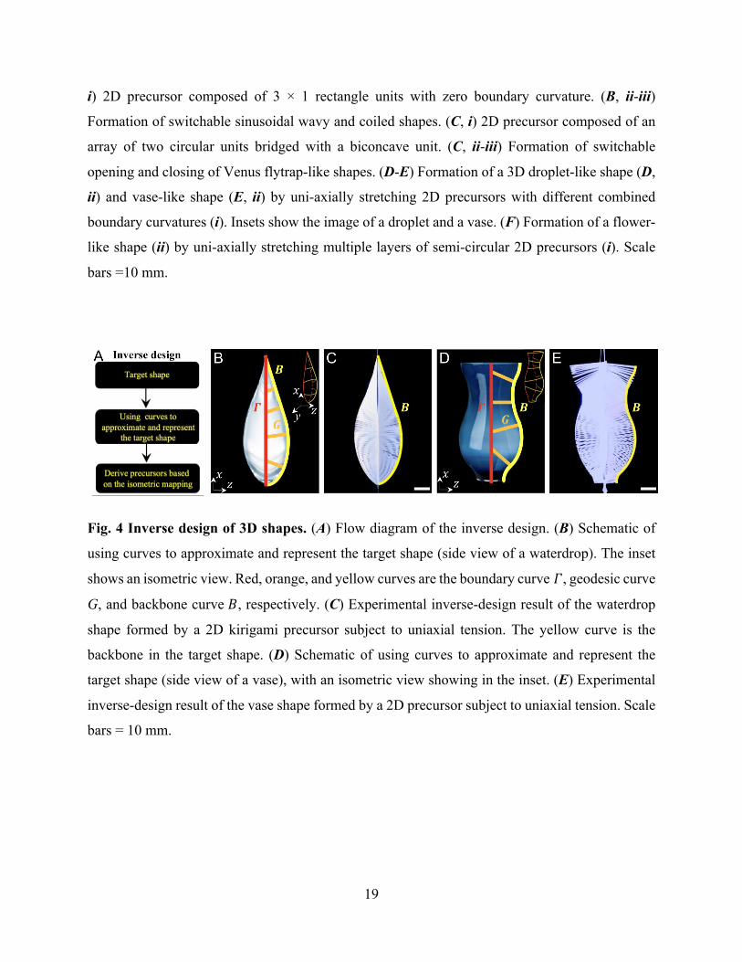
Inverse design strategy
Existing methods of inverse design for target 3D curved shapes using the kirigami approach
require complex algorithms to program heterogeneous local deformation among networked cut
units (33, 34). Based on the information that discrete ribbons are geodesic curves of the deformed
3D shapes, we propose a straightforward inverse design strategy. It utilizes the geodesic curves
extracted from the target shapes and the isometric mapping to prescribe the 2D precursors (Fig. 4
A), which is, in principle, applicable to any target configuration.
To illustrate the strategy, we use the target shapes of a water droplet (Fig. 4 B) and a vase (Fig. 4
D) as two examples for the inverse design of the 2D kirigami precursors. As shown in Fig. 4 B
and D, we first approximate and represent the target shapes by deriving the shape functions of the
backbone curve B (highlighted in yellow color, see details in Supplementary Materials, Section
S6), the geodesic curves G (highlighted in orange color) approximated by elastica curves, and the
boundary curve Г (highlighted in red color). Next, based on the isometric mapping from G and Г
in the target shape to the 2D precursor, we derive the shape function of the prescribed 2D boundary
curve Г P (Supplementary Materials, Section S6). The parametrization of Г and Г P can be
expressed in the form of and , respectively, where
the superscript P represents the 2D precursor. Accordingly, the shape function of the boundary
curve Г P in the 2D precursor can be derived as (see details in Supplementary Materials, Section
S6)
[4]
where the parameters of ηx and ηy are related to the isometric mapping. Furthermore, the required
strain εre to form the target shape is given by
with max(sb) being the maximum arc length of the boundary ribbon.
( ) ( )( )Γ , ,0b br x s y s=! ( ) ( )( )Γ, ,0P
P Pb br x s y s=!
( )( )
( )( )
0 0
Pb bx
Py bb
x s x s
y sy s
hh
ì ü ì üé ùï ï ï ï=í ý í ýê úï ïï ï ë û î þî þ
( ) ( ) ( )max( ) max( ) max( )P Pre b b bx s x s x se é ù= -ë û

10
Fig. 4 C and E show the result of the inverse design of a water droplet and a vase after deploying
the derived 2D kirigami precursors at an applied strain of εre = 0.14 and 0.07, respectively. The
inverse design result agrees well with the target shape denoted by the yellow curves. Notably,
precise control of all the geodesic curves is not necessary for our proposed inverse design approach
since it only needs the information of one representative geodesic curve and one boundary curve
in the target surface. Thus, such a strategy could significantly simplify the calculation
(Supplementary Materials, Section S6). The accuracy can be further improved by increasing the
number of geodesic curves deriving from the target surface and optimizing the approximation of
geodesics.
Remote magnetic actuation and proof-of-concept potential robotic application
In addition to the contact-based mechanical actuation for shape morphing, we also demonstrate
the capability of achieving similar 2D-to-3D shape shifting and bistability in kirigami sheets
through remote magnetic actuation. By attaching a magnetic pad to one end of the 2D circular
kirigami precursor with the other end fixed, Fig. 5 A shows a similar shape shifting into a
spheroidal shape under an applied remote translational magnetic field to that under mechanical
stretching (Supplementary Video S4). Given the flexibility of the discrete ribbons, the 2D circular
kirigmi precursor could also be twisted into a pine-cone shape under either an applied rotational
magnetic field or a mechanical twisting (Supplementary Video S5 and Fig. S9a). Similarly, by
attaching magnetic thin polymeric stripes to the discrete ribbons (Fig. 5 B, i), we could use a
remote translational magnetic field to fast switch the bistable states in the ribbons to reconfigure
the kirigami structure. Fig. 5 B, ii-v show a sequential snapping of the discrete ribbons in the
spheroidal structure (Supplementary Video S6), where its sequence could be tuned via the
distribution of the magnetic polymers in the 2D kirigami precursor (Supplementary Materials,
Section S7).
Lastly, to demonstrate the advantages of both remote magnetic actuation and the proposed kirigami
design, we explore its potential application in designing an untethered predator-like flexible robot
as a proof of concept. The flexible kirigami robot mimics the rolled-up pill millipede to predate a
target object, where a tiny rock is used to simulate the prey and its irregular shape is to demonstrate
the capability of delicate manipulation and adaptability of the kirigami flexible body (Fig. 5 C, i).
As shown in Fig. 5 C, ii-v and Supplementary Video S7, the predating and releasing process

11
consists of three steps. (1) Catching by moving and rotating itself around x-axis to cover the object
under an applied rotational magnetic field around x-axis in Fig. 5 C, ii, followed by relocating the
object to a different spot under a translational magnetic field (Fig. 5 C, iii). (2) “Swallowing” the
object through curling its flexible body along the minor axis to wrap the irregular rock inside under
a rotational magnetic field around y-axis (Fig. 5 C, iv). It should note that the flexible body adapts
and conforms to the irregular shape of the rock by tightly wrapping around it, the deformation and
dynamic shape morphing of which is challenging to be realized by contact-based mechanical
actuation. (3) Carrying the “swallowed” object to a new spot followed by object releasing through
recovering to its undeformed configuration (Fig. 5 C, v). An alternative way to “swallow” the
object is also demonstrated by curling its body along the major axis under a rotational magnetic
field around x axis (Fig. S9b and Supplementary Video S8), which mimics the snake-coiling. The
discrete ribbon-based kirigami design shows the unique features of flexibility, conformability, and
adaptivity, which can help to accommodate remotely actuated complex dynamic shape morphing
that could not be achieved by mechanical actuation, and thus facilitate the target robotic multitasks
of locomotion and manipulation during predation.
DISCUSSION
We proposed a new way of utilizing the cut boundary curvature to guide the formation of
controllable and reconfigurable complex 3D curved shapes in kirigami sheets patterned with
simple parallel cuts. Such a strategy is validated through combined theoretical modeling, FEM
simulations, and experiments. The unique feature of discrete cut ribbons as geodesic curves of the
deformed 3D shapes largely simplifies the inverse design. Beyond contact-based mechanical
stretching, we demonstrated that the strategy could also apply to the remote magnetic actuation for
enhanced shape-morphing capability in kirigami sheets imparted with potential untethered robotic
functionality.
It should note that the shape shifting in the studied thermoplastic kirigami sheets is fully reversible,
i.e., the generated 3D shape will return to its original flat form after the external actuation is
removed due to elastic deformation in the kirigami structure. To preserve the deformed 3D shapes,
we could utilize the shape memory properties of the PET polymer upon heating above its glass

12
transition temperature (39). We use thermal treatment under 120 oC to treat the 3D shapes held at
an applied stretching strain for a period of 120 min and cooled down to the room temperature to
fix the deformed configuration (see the demonstration of a fixed 3D spheroidal shape in Fig. S10).
Notably, the preserved 3D configuration can be further deformed and recover to its 2D flat
precursor shape upon another thermal treatment (Fig. S10).
Despite the demonstration of programmable shaft shifting in the thermoplastic kirigami sheets, we
envision that the proposed strategy is material and scale independent. We note that despite the
large applied stretching strain ε, the maximum principal strain εmax in the buckled ribbons with
thickness of 127 μm remains small (εmax < 1% for ε > 50%, Fig. S11, Supplementary Materials,
Section S3), e.g., εmax = 0.4% in the deformed spherical shape at ε = 30% (Fig. 2 A, iv) and εmax =
0.6% in the saddle shape at ε = 147% (Fig. 2 B, iv). Considering the small peak tensile strain in
the buckled ribbons and its linear relationship with sheet thickness t, i.e., εmax decreases linearly
with t, we envision that the proposed kirigami strategy could also be applied to design shape-
morphing and stretchable structures and devices made of other functional materials such as metals
and even semiconductors at small scales, as well as other stimuli-responsive materials actuated by
temperature, electrical, and magnetic field, etc. This work could find potential applications in
designing stretchable electronics, reconfigurable devices, soft robots, and mechanical self-
assembly fabrication.
MATERIALS AND METHODS
Details on fabrication of 2D kirigami precursors, finite element simulation, theoretical modeling,
and inverse designs are described in the Supplementary Materials.
Acknowledgments: Funding: J. Y. acknowledges the funding support from the National Science
Foundation under award number CAREER-2005374 and 2013993. Author contributions: Y.H.
and J. Y. designed research; Y. H., Y. C., and Y. Li performed research; Y. H., Y. C., Y. Li, Y. Z.,
and J. Y. analyzed data; Y. H. and J. Y. wrote the paper.
Competing interests: The authors declare no competing interests. Data and materials
availability: All data is available in the main text or the supplementary materials.
SUPPLEMENTARY MATERIALS

13
Text
Fig. S1 to S11
Movie S1 to S8
Reference Notes
References
1. Y. Liu, J. Genzer, M. D. Dickey, “2D or not 2D”: Shape-programming polymer sheets. Progress in Polymer Science 52, 79-106 (2016).
2. T. van Manen, S. Janbaz, A. A. Zadpoor, Programming the shape-shifting of flat soft matter. Materials Today 21, 144-163 (2018).
3. E. Hawkes, B. An, N. M. Benbernou, H. Tanaka, S. Kim, E. D. Demaine, D. Rus, R. J. Wood, Programmable matter by folding. Proceedings of the National Academy of Sciences 107, 12441-12445 (2010).
4. S. Felton, M. Tolley, E. Demaine, D. Rus, R. Wood, A method for building self-folding machines. Science 345, 644-646 (2014).
5. C. L. Randall, E. Gultepe, D. H. Gracias, Self-folding devices and materials for biomedical applications. Trends in Biotechnology 30, 138-146 (2012).
6. F. Momeni, S. M.Mehdi Hassani.N, X. Liu, J. Ni, A review of 4D printing. Materials & Design 122, 42-79 (2017).
7. X. Kuang, D. J. Roach, J. Wu, C. M. Hamel, Z. Ding, T. Wang, M. L. Dunn, H. J. Qi, Advances in 4D Printing: Materials and Applications. Advanced Functional Materials 29, 1805290 (2019).
8. S. J. P. Callens, A. A. Zadpoor, From flat sheets to curved geometries: Origami and kirigami approaches. Materials Today 21, 241-264 (2018).
9. X. Ning, X. Wang, Y. Zhang, X. Yu, D. Choi, N. Zheng, D. S. Kim, Y. Huang, Y. Zhang, J. A. Rogers, Assembly of Advanced Materials into 3D Functional Structures by Methods Inspired by Origami and Kirigami: A Review. Advanced Materials Interfaces 5, 1800284 (2018).
10. Y. Tang, Y. Li, Y. Hong, S. Yang, J. Yin, Programmable active kirigami metasheets with more freedom of actuation. Proceedings of the National Academy of Sciences 116, 26407-26413 (2019).
11. J. N. Grima, A. Alderson, K. E. Evans, Auxetic behaviour from rotating rigid units. physica status solidi (b) 242, 561-575 (2005).
12. A. Rafsanjani, K. Bertoldi, Buckling-Induced Kirigami. Physical Review Letters 118, 084301 (2017).
13. S. Shan, S. H. Kang, Z. Zhao, L. Fang, K. Bertoldi, Design of planar isotropic negative Poisson’s ratio structures. Extreme Mechanics Letters 4, 96-102 (2015).
14. Y. Tang, J. Yin, Design of cut unit geometry in hierarchical kirigami-based auxetic metamaterials for high stretchability and compressibility. Extreme Mechanics Letters 12, 77-85 (2017).
15. Z. Qi, D. K. Campbell, H. S. Park, Atomistic simulations of tension-induced large deformation and stretchability in graphene kirigami. Physical Review B 90, 245437 (2014).

14
16. Y. Cho, J.-H. Shin, A. Costa, T. A. Kim, V. Kunin, J. Li, S. Y. Lee, S. Yang, H. N. Han, I.-S. Choi, D. J. Srolovitz, Engineering the shape and structure of materials by fractal cut. Proceedings of the National Academy of Sciences 111, 17390-17395 (2014).
17. M. K. Blees, A. W. Barnard, P. A. Rose, S. P. Roberts, K. L. McGill, P. Y. Huang, A. R. Ruyack, J. W. Kevek, B. Kobrin, D. A. Muller, P. L. McEuen, Graphene kirigami. Nature 524, 204-207 (2015).
18. T. C. Shyu, P. F. Damasceno, P. M. Dodd, A. Lamoureux, L. Xu, M. Shlian, M. Shtein, S. C. Glotzer, N. A. Kotov, A kirigami approach to engineering elasticity in nanocomposites through patterned defects. Nature Materials 14, 785-789 (2015).
19. Y. Tang, G. Lin, L. Han, S. Qiu, S. Yang, J. Yin, Design of Hierarchically Cut Hinges for Highly Stretchable and Reconfigurable Metamaterials with Enhanced Strength. Advanced Materials 27, 7181-7190 (2015).
20. D.-G. Hwang, M. D. Bartlett, Tunable Mechanical Metamaterials through Hybrid Kirigami Structures. Scientific Reports 8, 3378 (2018).
21. Y. Yang, M. A. Dias, D. P. Holmes, Multistable kirigami for tunable architected materials. Physical Review Materials 2, 110601 (2018).
22. Z. Liu, H. Du, J. Li, L. Lu, Z.-Y. Li, N. X. Fang, Nano-kirigami with giant optical chirality. Science Advances 4, eaat4436 (2018).
23. R. M. Neville, F. Scarpa, A. Pirrera, Shape morphing Kirigami mechanical metamaterials. Scientific Reports 6, 31067 (2016).
24. Z. Song, X. Wang, C. Lv, Y. An, M. Liang, T. Ma, D. He, Y.-J. Zheng, S.-Q. Huang, H. Yu, H. Jiang, Kirigami-based stretchable lithium-ion batteries. Scientific Reports 5, 10988 (2015).
25. Y.-S. Guan, Z. Zhang, Y. Tang, J. Yin, S. Ren, Kirigami-Inspired Nanoconfined Polymer Conducting Nanosheets with 2000% Stretchability. Advanced Materials 30, 1706390 (2018).
26. Y. Zhang, Z. Yan, K. Nan, D. Xiao, Y. Liu, H. Luan, H. Fu, X. Wang, Q. Yang, J. Wang, W. Ren, H. Si, F. Liu, L. Yang, H. Li, J. Wang, X. Guo, H. Luo, L. Wang, Y. Huang, J. A. Rogers, A mechanically driven form of Kirigami as a route to 3D mesostructures in micro/nanomembranes. Proceedings of the National Academy of Sciences 112, 11757-11764 (2015).
27. R. Zhao, S. Lin, H. Yuk, X. Zhao, Kirigami enhances film adhesion. Soft Matter 14, 2515-2525 (2018).
28. A. Rafsanjani, Y. Zhang, B. Liu, S. M. Rubinstein, K. Bertoldi, Kirigami skins make a simple soft actuator crawl. Science Robotics 3, eaar7555 (2018).
29. Y.-C. Cheng, H.-C. Lu, X. Lee, H. Zeng, A. Priimagi, Kirigami-Based Light-Induced Shape-Morphing and Locomotion. Advanced Materials 32, 1906233 (2020).
30. Y. Tang, G. Lin, S. Yang, Y. K. Yi, R. D. Kamien, J. Yin, Programmable Kiri-Kirigami Metamaterials. Advanced Materials 29, 1604262 (2017).
31. J. Cui, F. R. Poblete, Y. Zhu, Origami/Kirigami-Guided Morphing of Composite Sheets. Advanced Functional Materials 28, 1802768 (2018).
32. P. Celli, C. McMahan, B. Ramirez, A. Bauhofer, C. Naify, D. Hofmann, B. Audoly, C. Daraio, Shape-morphing architected sheets with non-periodic cut patterns. Soft Matter 14, 9744-9749 (2018).
33. G. P. T. Choi, L. H. Dudte, L. Mahadevan, Programming shape using kirigami tessellations. Nature Materials 18, 999-1004 (2019).

15
34. L. Jin, A. E. Forte, B. Deng, A. Rafsanjani, K. Bertoldi, Kirigami-Inspired Inflatables with Programmable Shapes. Advanced Materials 32, 2001863 (2020).
35. Spivak M., A Comprehensive Introduction to Differential Geometry. (Publish or Perish, Boston, 1970), vol. 1.
36. R. Levien, "The elastica: a mathematical history," (EECS Department, University of California, Berkeley, 2008).
37. P. Djondjorov, M. Hadzhilazova, I. Mladenov, V. Vassilev, Explicit Parameterization of Euler’s Elastica. Geom. Integrability & Quantization 9, 175-186 (2008).
38. S. Timoshenko, J. Gere, Theory of Elastic Stability. (McGraw-Hill, New York, 1961). 39. L. Wu Xue, P. Yang Chuan, Q. Guo Yu, Y. Wang Hong, Triple-shape memory effect in
poly (ethylene terephthalate) (PET) film. Pigment & Resin Technology 47, 55-62 (2018).

16
Figures:
Fig. 1 Shape shifting of 3D curved topologies from 2D kirigami sheets with different cut
boundary curvatures subject to uniaxial tension. (A-C) Left column: 2D precursors of three
kirigami sheets patterned with parallel cuts but different boundary curvatures kb highlighted in
dashed white curves. Circular (A), square (B), biconcave (C) samples with positive, zero, and
negative boundary curvature, respectively. Right column: Formed 3D curved shapes with different
Gaussian curvature K. (A) Spheroidal shape with K > 0 at an applied strain of 0.30. (B) Cylindrical
shape with K = 0 at an applied strain of 0.65. (C) Saddle shape with K < 0 at an applied strain of
1.47. Scale bars = 10 mm.
17
Fig. 2 Quantifying the 3D shape shifting through analytical modeling and simulation. (A, B)
Predicted shape changes with the applied strain ε in the samples of spheroidal (A) and saddle
shapes (B). (i) is the front-view profile. (ii) is the top-view profile. (iii) is the side-view profile. (iv)
is the overlapping of FEM simulation results (contours of the maximum principal strain εmax) with
the experimental image at ε = 0.30 (A) and 1.47 (B). (C, D) Theoretically predicted 3D maps of
the normalized Gaussian curvature at the center point C as a function of the normalized
boundary curvature in 2D kirigami precursors (insets) and the applied strain ε for the cases of
spherical (C) and saddle (D) shapes. (E) Theoretical and experimental results of the approximately
linear relationship between the normalized variation of the Gaussian curvature and the
normalized variation of the boundary curvature . Scale bars = 10 mm.
K
bok
max| |K KD
| |b bok kD

18
Fig. 3 Combinatorial designs of 2D kirigami precursors for complex 3D shapes under
uniaxial tension. (A-C) Reconfigurable 3D shapes through bistability of discrete ribbons. (A, i)
2D precursor composed of 2 × 2 square units with zero boundary curvature. (A, ii-iv) uni-axial
stretching induced reconfigurable human face-like topologies with switchable smiley (ii) and sad
(iii) expressions, as well as eyeglasses (iv) by tuning the popping directions of ribbons (insets). (B,
19
i) 2D precursor composed of 3 × 1 rectangle units with zero boundary curvature. (B, ii-iii)
Formation of switchable sinusoidal wavy and coiled shapes. (C, i) 2D precursor composed of an
array of two circular units bridged with a biconcave unit. (C, ii-iii) Formation of switchable
opening and closing of Venus flytrap-like shapes. (D-E) Formation of a 3D droplet-like shape (D,
ii) and vase-like shape (E, ii) by uni-axially stretching 2D precursors with different combined
boundary curvatures (i). Insets show the image of a droplet and a vase. (F) Formation of a flower-
like shape (ii) by uni-axially stretching multiple layers of semi-circular 2D precursors (i). Scale
bars =10 mm.
Fig. 4 Inverse design of 3D shapes. (A) Flow diagram of the inverse design. (B) Schematic of
using curves to approximate and represent the target shape (side view of a waterdrop). The inset
shows an isometric view. Red, orange, and yellow curves are the boundary curve 𝛤, geodesic curve
G, and backbone curve 𝐵, respectively. (C) Experimental inverse-design result of the waterdrop
shape formed by a 2D kirigami precursor subject to uniaxial tension. The yellow curve is the
backbone in the target shape. (D) Schematic of using curves to approximate and represent the
target shape (side view of a vase), with an isometric view showing in the inset. (E) Experimental
inverse-design result of the vase shape formed by a 2D precursor subject to uniaxial tension. Scale
bars = 10 mm.
20
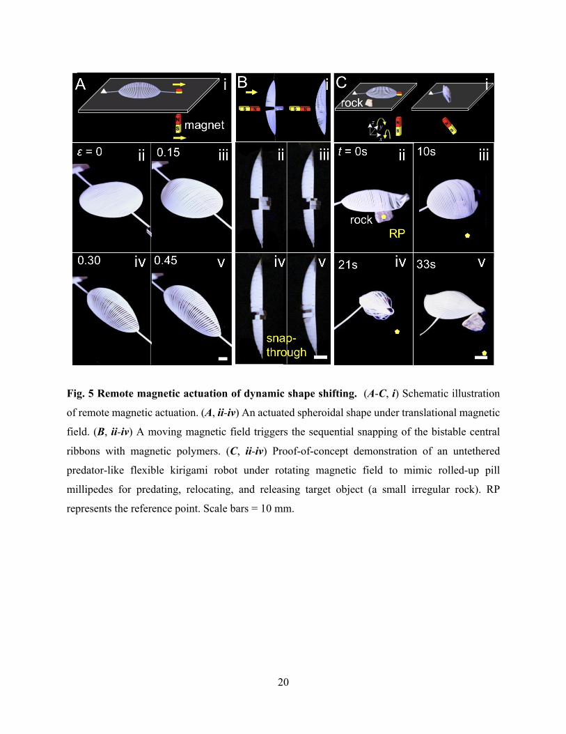
Fig. 5 Remote magnetic actuation of dynamic shape shifting. (A-C, i) Schematic illustration
of remote magnetic actuation. (A, ii-iv) An actuated spheroidal shape under translational magnetic
field. (B, ii-iv) A moving magnetic field triggers the sequential snapping of the bistable central
ribbons with magnetic polymers. (C, ii-iv) Proof-of-concept demonstration of an untethered
predator-like flexible kirigami robot under rotating magnetic field to mimic rolled-up pill
millipedes for predating, relocating, and releasing target object (a small irregular rock). RP
represents the reference point. Scale bars = 10 mm.