borg warner p38
TRANSCRIPT

BORG WARNER44-62
TRANSFER BOX
OVERHAULMANUAL
This transfer box is used on thefollowing models:
New Range Rover
Published by Rover Technical Communication
1996 Rover Group LimitedPublication Part No. LRL 0090ENG
INTRODUCTION
INFORMATION 1
INTRODUCTION
How to use this Manual
To assist in the use of this Manual the section title isgiven at the top and the relevant sub-section is givenat the bottom of each page.
This Manual contains procedures for overhaul of theBorg Warner transfer gearbox on the bench. For allother information regarding General Information,Adjustments, removal of transmission unit andancillary equipment, consult the relevant section ofthe New Range Rover Workshop Manual.
This Manual is divided into 3 sections, Descriptionand Operation, Overhaul and Torque & Tools. Toassist filing of revised information each sub-sectionis numbered from page 1.
Items numbered in the illustrations are referred to inthe text. Overhaul operations include reference toService Tool numbers and the associated illustrationdepicts the tool. Where usage is not obvious the toolis shown in use. Operations also include referenceto wear limits, relevant data, torque figures, andspecialist information and useful assembly details.
WARNINGS, CAUTIONS and NOTES have thefollowing meanings:
WARNING: Procedures which must befollowed precisely to avoid the possibilityof injury.
CAUTION: Calls attention to procedureswhich must be followed to avoid damageto components.
NOTE: Gives helpful information.
References
Operations covered in this Manual do not includereference to testing the vehicle after repair. It isessential that work is inspected and tested aftercompletion and if necessary a road test of thevehicle is carried out particularly where safetyrelated items are concerned.
Dimensions
The dimensions quoted are to design engineeringspecification with Service limits where applicable.
INTRODUCTION
2 INFORMATION
REPAIRS AND REPLACEMENTS
When replacement parts are required it is essentialthat only Land Rover recommended parts are used.
Attention is particularly drawn to the following pointsconcerning repairs and the fitting of replacementparts and accessories.
Safety features and corrosion prevention treatmentsembodied in the vehicle may be impaired if otherthan Land Rover recommended parts are fitted. Incertain territories, legislation prohibits the fitting ofparts not to the manufacturer’s specification.
Torque wrench setting figures given in this Manualmust be used. Locking devices, where specified,must be fitted. If the efficiency of a locking device isimpaired during removal it must be renewed.
The Terms of the vehicle Warranty may beinvalidated by the fitting of other than Land Roverrecommended parts. All Land Rover recommendedparts have the full backing of the vehicle Warranty.
Land Rover Dealers are obliged to supply only LandRover recommended parts.
SPECIFICATION
Land Rover are constantly seeking to improve thespecification, design and production of their vehiclesand alterations take place accordingly. While everyeffort has been made to ensure the accuracy of thisManual, it should not be regarded as an infallibleguide to current specifications of any particularcomponent or vehicle.
This Manual does not constitute an offer for sale ofany particular component or vehicle. Land RoverDealers are not agents of Land Rover and have noauthority to bind the manufacturer by any expressedor implied undertaking or representation.

TRANSFER BOX
DESCRIPTION AND OPERATION 1
GEARBOX COMPONENTS
1. Front casing - transfer box2. Bolt - front casing to rear casing3. Dowel - transfer box to gearbox4. Viscous coupling5. Housing - viscous coupling6. Bolt - viscous coupling housing to front casing7. Bearing - front output shaft8. Circlip - bearing retention9. Oil seal - front output shaft
10. Drive flange - front output shaft11. Sealing washer12. Plain washer13. Nut - drive flange14. Circlip - epicyclic gear to bearing15. Oil seal - input shaft16. Epicyclic gear set17. Circlip - bearing retention18. Bearing - input shaft
TRANSFER BOX
2 DESCRIPTION AND OPERATION
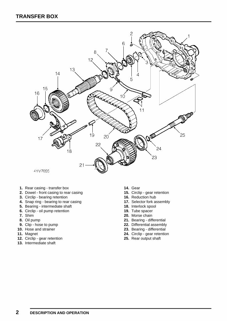
1. Rear casing - transfer box2. Dowel - front casing to rear casing3. Circlip - bearing retention4. Snap ring - bearing to rear casing5. Bearing - intermediate shaft6. Circlip - oil pump retention7. Shim8. Oil pump9. Clip - hose to pump
10. Hose and strainer11. Magnet12. Circlip - gear retention13. Intermediate shaft
14. Gear15. Circlip - gear retention16. Reduction hub17. Selector fork assembly18. Interlock spool19. Tube spacer20. Morse chain21. Bearing - differential22. Differential assembly23. Bearing - differential24. Circlip - gear retention25. Rear output shaft

TRANSFER BOX
DESCRIPTION AND OPERATION 3
1. Rear casing - transfer box2. Plug - oil drain3. Plug - oil fill4. Sealing washer - temperature sensor5. Temperature sensor6. Parking brake assembly7. Bolt - parking brake to rear casing8. Bearing - rear output shaft9. Circlip - bearing retention
10. Oil seal - rear output shaft11. Dust shroud
12. Drive flange - rear output shaft13. Sealing washer14. Plain washer15. Nut - drive flange16. Drum - parking brake17. Screw - drum to flange18. Oil seal - interlock spool shaft19. ’O’ ring seal - speed sensor20. Speed sensor21. Bolt - speed sensor22. Bolt - ratio control motor to rear casing23. Ratio control motor
TRANSFER BOX
4 DESCRIPTION AND OPERATION
OPERATION
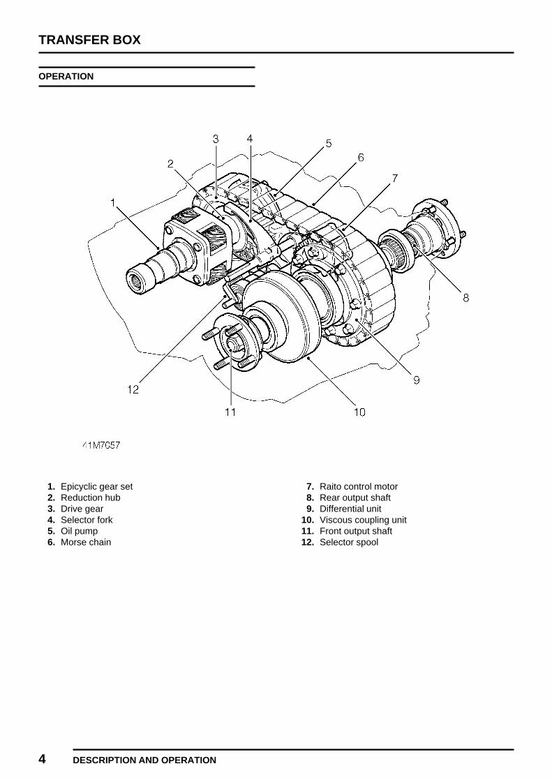
1. Epicyclic gear set2. Reduction hub3. Drive gear4. Selector fork5. Oil pump6. Morse chain
7. Raito control motor8. Rear output shaft9. Differential unit
10. Viscous coupling unit11. Front output shaft12. Selector spool
TRANSFER BOX
DESCRIPTION AND OPERATION 5
Introduction
The Borg Warner transfer box splits the drive fromthe main gearbox to the front and rear axles throughthe propeller shafts. Two speed ratios and a neutralposition are provided by means of a single, epicyclicgear set. The two speed ratios, High and Low range,and neutral position are selected electronically bythe ratio control motor.
A Morse chain transmits the drive through a gearfrom the intermediate shaft to the differential unit.The differential unit allows the front and rear outputshafts to rotate at different speeds. A viscouscoupling unit (VCU) limits the amount of slippageallowed between the front and rear output shafts andrenders a conventional differential lock unnecessary.
TRANSFER BOX
6 DESCRIPTION AND OPERATION
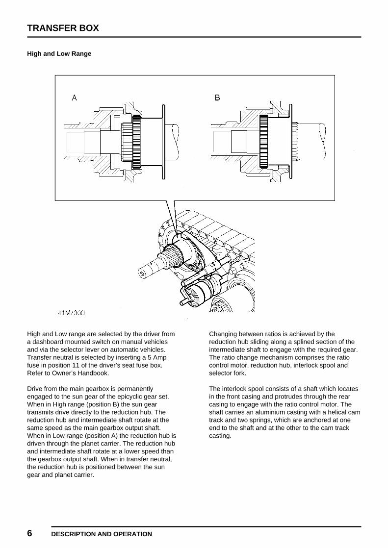
High and Low Range
High and Low range are selected by the driver froma dashboard mounted switch on manual vehiclesand via the selector lever on automatic vehicles.Transfer neutral is selected by inserting a 5 Ampfuse in position 11 of the driver’s seat fuse box.Refer to Owner’s Handbook.
Drive from the main gearbox is permanentlyengaged to the sun gear of the epicyclic gear set.When in High range (position B) the sun geartransmits drive directly to the reduction hub. Thereduction hub and intermediate shaft rotate at thesame speed as the main gearbox output shaft.When in Low range (position A) the reduction hub isdriven through the planet carrier. The reduction huband intermediate shaft rotate at a lower speed thanthe gearbox output shaft. When in transfer neutral,the reduction hub is positioned between the sungear and planet carrier.
Changing between ratios is achieved by thereduction hub sliding along a splined section of theintermediate shaft to engage with the required gear.The ratio change mechanism comprises the ratiocontrol motor, reduction hub, interlock spool andselector fork.
The interlock spool consists of a shaft which locatesin the front casing and protrudes through the rearcasing to engage with the ratio control motor. Theshaft carries an aluminium casting with a helical camtrack and two springs, which are anchored at oneend to the shaft and at the other to the cam trackcasting.
TRANSFER BOX
DESCRIPTION AND OPERATION 7
The selector fork is mounted on a second shaftlocated within the front and rear casings but is ableto slide in the casing mountings. A cam follower onthe selector fork engages with the cam track of theinterlock spool. When the ratio control motor rotatesthe interlock spool, the cam follower of the selectorfork follows the cam track of the interlock spool. Thisconverts rotational movement of the interlock spoolinto linear movement of the selector fork.
The selector fork is engaged to the reduction hub.Linear movement of the selector fork is transmittedto the reduction hub, moving it between High, Lowand neutral positions. In the event of the reductionhub gear failing to mesh with the epicyclic gear set,wind-up of the interlock is prevented by the interlockspool springs. The springs apply a constant torqueto the cam track casting until the reduction hubengages with the epicyclic gear.
Ratio control motor
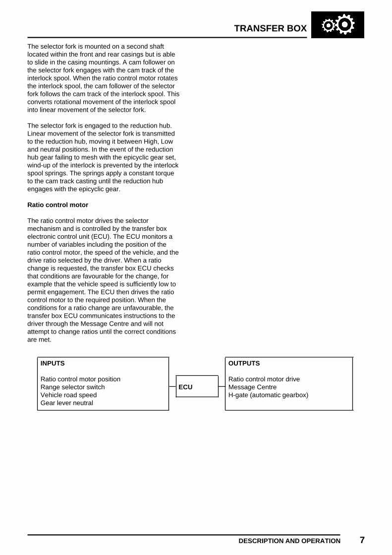
The ratio control motor drives the selectormechanism and is controlled by the transfer boxelectronic control unit (ECU). The ECU monitors anumber of variables including the position of theratio control motor, the speed of the vehicle, and thedrive ratio selected by the driver. When a ratiochange is requested, the transfer box ECU checksthat conditions are favourable for the change, forexample that the vehicle speed is sufficiently low topermit engagement. The ECU then drives the ratiocontrol motor to the required position. When theconditions for a ratio change are unfavourable, thetransfer box ECU communicates instructions to thedriver through the Message Centre and will notattempt to change ratios until the correct conditionsare met.
INPUTS OUTPUTS
Ratio control motor position Ratio control motor driveRange selector switch ECU Message CentreVehicle road speed H-gate (automatic gearbox)Gear lever neutral

TRANSFER BOX
8 DESCRIPTION AND OPERATION
Differential unit
The differential unit is driven from the intermediateshaft through a Morse chain. The outer casing of thedifferential unit is the differential input, while the sungear provides the front output and the planet carrierthe rear output.
The planet carrier contains three sets of gears,which mesh in pairs to maintain the correctdirectional relationship between front and reardifferential outputs. The rear output shaft passesthrough the differential unit, engaging with the planetcarrier and protruding through the sun gear shaft tolocate to the VCU inner spline. The sun gear shaftlocates to the VCU outer spline.

TRANSFER BOX
DESCRIPTION AND OPERATION 9
Viscous coupling (VCU)
The VCU comprises a short cylinder which containsan inner shaft with slotted discs attached to its outersurface, and a similar set of discs attached to theinner surface of the cylinder. Both sets of discs arearranged so that they interleave alternately and inclose proximity to each other. The VCU is sealed,and filled with a type of silicone jelly which has theproperty of increasing its viscosity with rises intemperature and shear forces.
Variations in speed between the front and rearoutput shafts are transmitted through the VCU, withthe speed differential occurring between the innershaft and the cylinder. In normal road conditionswhere the speed variation between front and rearshafts is low, the difference in rotational speedbetween the VCU discs is also low. As a result, theshear forces acting on the silicon jelly are marginaland offer little resistance to the different rotationalspeeds of the output shafts.
In cases where large rotational speed differencesoccur between the front and rear output shafts, suchas in rough terrain conditions, the speed variationbetween the discs is high with a subsequentincrease in the shear forces acting on the viscousjelly. The resulting increase in viscosity generatessufficient shear resistance to force both sets of discsto rotate at similar speeds, reducing axle slippageand loss of traction.
TRANSFER BOX
10 DESCRIPTION AND OPERATION
Lubrication
Internal lubrication of the transfer gearbox isprovided by a low pressure, plunger-type oil pumpmounted on the rear of the intermediate shaft. Oilpick-up is through a strainer in the transfer boxsump. From the pump, oil is supplied through theintermediate shaft to the epicyclic gear set. Thedifferential and Morse chain are partially immersedin oil and lubricated as the components rotate. TheVCU is a fully sealed unit and does not requireseparate lubrication.
TRANSFER BOX
OVERHAUL 1
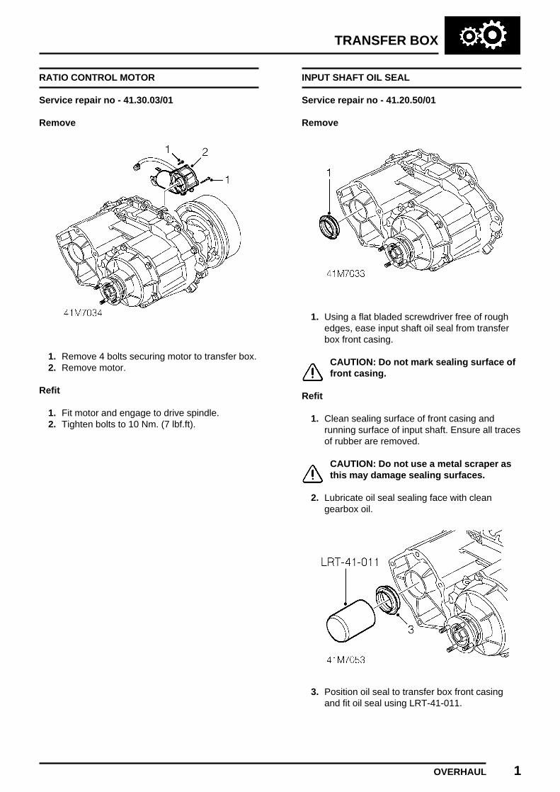
RATIO CONTROL MOTOR
Service repair no - 41.30.03/01
Remove
1. Remove 4 bolts securing motor to transfer box.2. Remove motor.
Refit
1. Fit motor and engage to drive spindle.2. Tighten bolts to 10 Nm. (7 lbf.ft).
INPUT SHAFT OIL SEAL
Service repair no - 41.20.50/01
Remove
1. Using a flat bladed screwdriver free of roughedges, ease input shaft oil seal from transferbox front casing.
CAUTION: Do not mark sealing surface offront casing.
Refit
1. Clean sealing surface of front casing andrunning surface of input shaft. Ensure all tracesof rubber are removed.
CAUTION: Do not use a metal scraper asthis may damage sealing surfaces.
2. Lubricate oil seal sealing face with cleangearbox oil.
3. Position oil seal to transfer box front casingand fit oil seal using LRT-41-011.
TRANSFER BOX
2 OVERHAUL
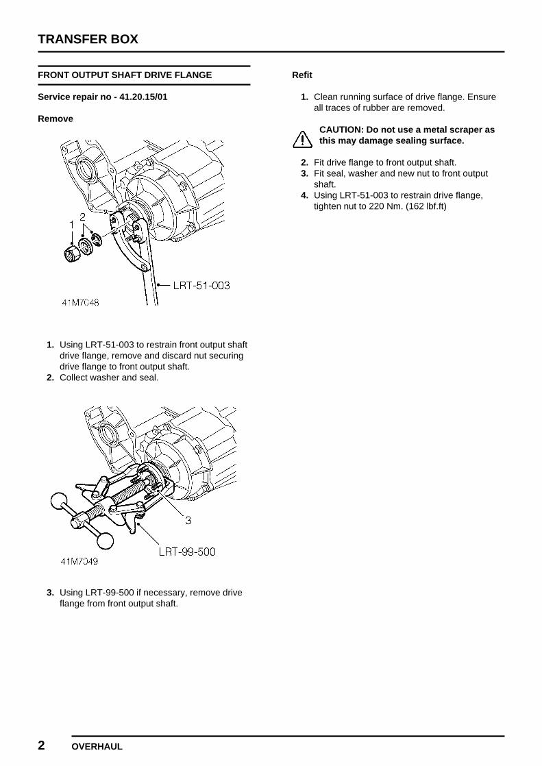
FRONT OUTPUT SHAFT DRIVE FLANGE
Service repair no - 41.20.15/01
Remove
1. Using LRT-51-003 to restrain front output shaftdrive flange, remove and discard nut securingdrive flange to front output shaft.
2. Collect washer and seal.
3. Using LRT-99-500 if necessary, remove driveflange from front output shaft.
Refit
1. Clean running surface of drive flange. Ensureall traces of rubber are removed.
CAUTION: Do not use a metal scraper asthis may damage sealing surface.
2. Fit drive flange to front output shaft.3. Fit seal, washer and new nut to front output
shaft.4. Using LRT-51-003 to restrain drive flange,
tighten nut to 220 Nm. (162 lbf.ft)
TRANSFER BOX
OVERHAUL 3
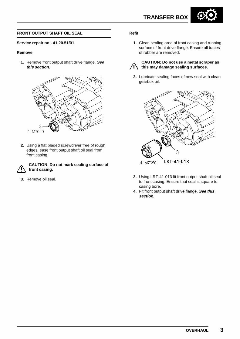
FRONT OUTPUT SHAFT OIL SEAL
Service repair no - 41.20.51/01
Remove
1. Remove front output shaft drive flange. Seethis section.
2. Using a flat bladed screwdriver free of roughedges, ease front output shaft oil seal fromfront casing.
CAUTION: Do not mark sealing surface offront casing.
3. Remove oil seal.
Refit
1. Clean sealing area of front casing and runningsurface of front drive flange. Ensure all tracesof rubber are removed.
CAUTION: Do not use a metal scraper asthis may damage sealing surfaces.
2. Lubricate sealing faces of new seal with cleangearbox oil.
3. Using LRT-41-013 fit front output shaft oil sealto front casing. Ensure that seal is square tocasing bore.
4. Fit front output shaft drive flange. See thissection.
TRANSFER BOX
4 OVERHAUL
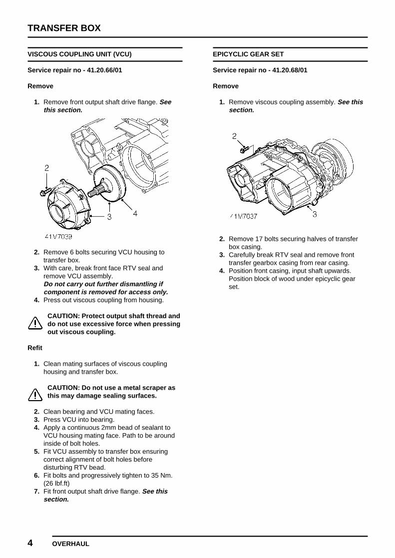
VISCOUS COUPLING UNIT (VCU)
Service repair no - 41.20.66/01
Remove
1. Remove front output shaft drive flange. Seethis section.
2. Remove 6 bolts securing VCU housing totransfer box.
3. With care, break front face RTV seal andremove VCU assembly.Do not carry out further dismantling ifcomponent is removed for access only.
4. Press out viscous coupling from housing.
CAUTION: Protect output shaft thread anddo not use excessive force when pressingout viscous coupling.
Refit
1. Clean mating surfaces of viscous couplinghousing and transfer box.
CAUTION: Do not use a metal scraper asthis may damage sealing surfaces.
2. Clean bearing and VCU mating faces.3. Press VCU into bearing.4. Apply a continuous 2mm bead of sealant to
VCU housing mating face. Path to be aroundinside of bolt holes.
5. Fit VCU assembly to transfer box ensuringcorrect alignment of bolt holes beforedisturbing RTV bead.
6. Fit bolts and progressively tighten to 35 Nm.(26 lbf.ft)
7. Fit front output shaft drive flange. See thissection.
EPICYCLIC GEAR SET
Service repair no - 41.20.68/01
Remove
1. Remove viscous coupling assembly. See thissection.
2. Remove 17 bolts securing halves of transferbox casing.
3. Carefully break RTV seal and remove fronttransfer gearbox casing from rear casing.
4. Position front casing, input shaft upwards.Position block of wood under epicyclic gearset.

TRANSFER BOX
OVERHAUL 5
5. Using a flat bladed screwdriver free of roughedges, ease input shaft oil seal from frontcasing.
CAUTION: Do not mark sealing surface offront casing.
6. Release circlip retaining epicyclic gear to frontcasing. Epicyclic gear set will fall onto block ofwood.
7. Remove epicyclic gear set.
Refit
1. Clean RTV sealant from front and rear casingmating surfaces.
CAUTION: Do not use a metal scraper asthis may damage sealing surfaces.
2. Clean bearing and input shaft mating faces.3. Clean sealing area of front casing and running
surface of input shaft. Ensure all traces ofrubber are removed from sealing surfaces.
CAUTION: Do not use a metal scraper asthis may damage sealing surfaces.
4. Fit epicyclic gear set to front casing.5. Fit circlip retaining epicyclic gear set to front
casing.6. Lubricate sealing faces of seal with clean
gearbox oil.
7. Using LRT-41-011 drift input shaft seal intofront casing.
8. If removed, fit 2 dowels to front casing.9. Apply a continuous 2 mm bead of RTV sealant
to rear casing mating face. Path to be aroundinside of bolt holes.
10. Fit front casing to rear casing, ensure boltholes are aligned before disturbing RTVsealant.
11. Fit bolts securing front casing to rear casingand progressively tighten to 35 Nm. (26 lbf.ft)
12. Check freedom of rotation of input shaft andthat rear output shaft rotates.
13. Fit viscous coupling assembly. See thissection.
TRANSFER BOX
6 OVERHAUL
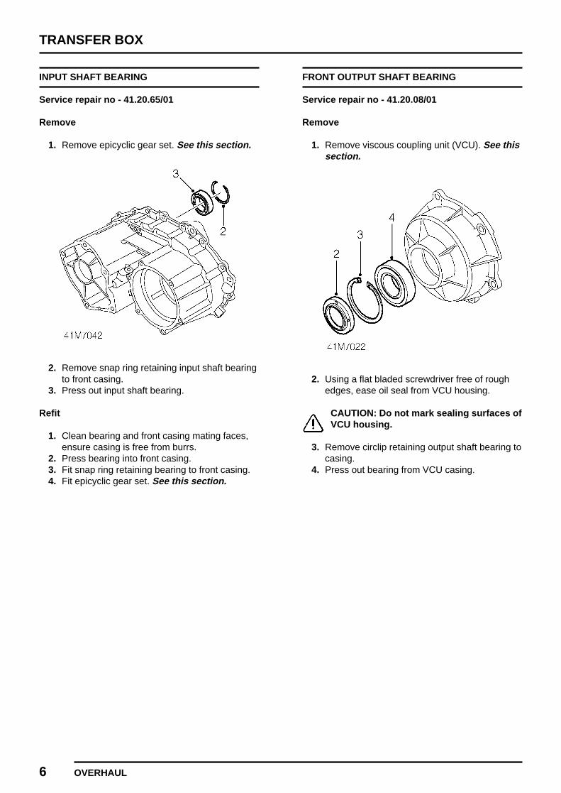
INPUT SHAFT BEARING
Service repair no - 41.20.65/01
Remove
1. Remove epicyclic gear set. See this section.
2. Remove snap ring retaining input shaft bearingto front casing.
3. Press out input shaft bearing.
Refit
1. Clean bearing and front casing mating faces,ensure casing is free from burrs.
2. Press bearing into front casing.3. Fit snap ring retaining bearing to front casing.4. Fit epicyclic gear set. See this section.
FRONT OUTPUT SHAFT BEARING
Service repair no - 41.20.08/01
Remove
1. Remove viscous coupling unit (VCU). See thissection.
2. Using a flat bladed screwdriver free of roughedges, ease oil seal from VCU housing.
CAUTION: Do not mark sealing surfaces ofVCU housing.
3. Remove circlip retaining output shaft bearing tocasing.
4. Press out bearing from VCU casing.
TRANSFER BOX
OVERHAUL 7
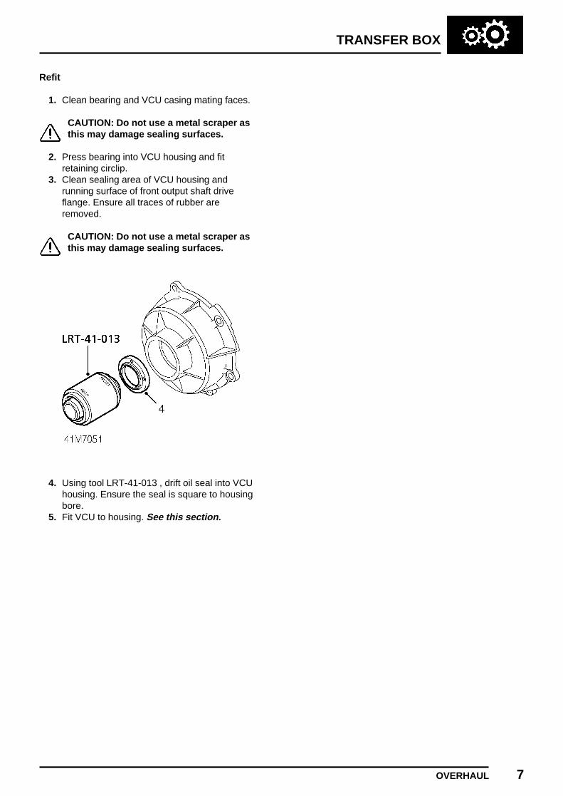
Refit
1. Clean bearing and VCU casing mating faces.
CAUTION: Do not use a metal scraper asthis may damage sealing surfaces.
2. Press bearing into VCU housing and fitretaining circlip.
3. Clean sealing area of VCU housing andrunning surface of front output shaft driveflange. Ensure all traces of rubber areremoved.
CAUTION: Do not use a metal scraper asthis may damage sealing surfaces.
4. Using tool LRT-41-013 , drift oil seal into VCUhousing. Ensure the seal is square to housingbore.
5. Fit VCU to housing. See this section.
TRANSFER BOX
8 OVERHAUL
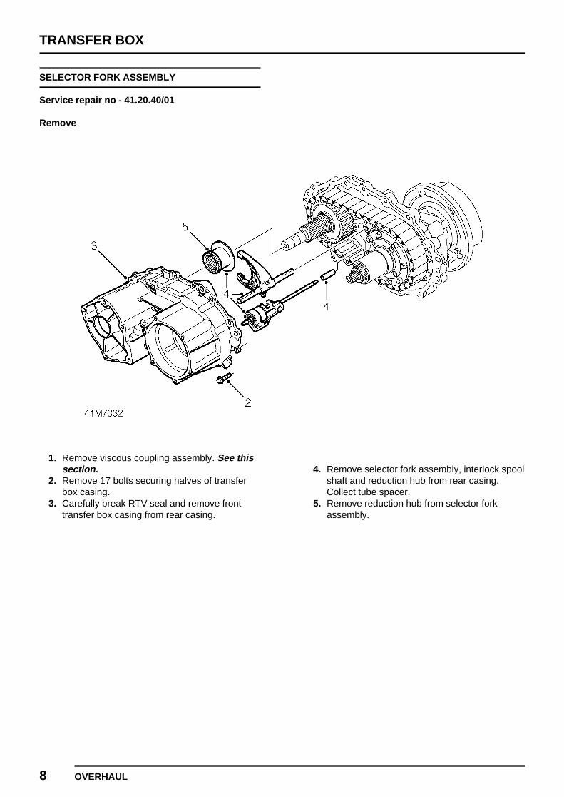
SELECTOR FORK ASSEMBLY
Service repair no - 41.20.40/01
Remove
1. Remove viscous coupling assembly. See thissection.
2. Remove 17 bolts securing halves of transferbox casing.
3. Carefully break RTV seal and remove fronttransfer box casing from rear casing.
4. Remove selector fork assembly, interlock spoolshaft and reduction hub from rear casing.Collect tube spacer.
5. Remove reduction hub from selector forkassembly.
TRANSFER BOX
OVERHAUL 9
Refit
1. Clean RTV sealant from front and rear casingmating surfaces.
CAUTION: Do not use a metal scraper asthis may damage sealing surfaces.
2. Fit reduction hub to selector fork assembly withhub splines towards the shorter end of shift rail.
3. Fit tube spacer to interlock spool shaft.4. Engage selector fork cam follower to interlock
spool cam track.5. Fit reduction hub to intermediate shaft and
engage interlock spool shaft and shift rail toholes in rear casing.
6. Rotate interlock spool shaft to positionreduction hub and selector fork to low ratioposition, nearest rear casing half. Ensure tubespacer is in position and selector fork camfollower is correctly engaged in interlock spool.
7. If removed, fit 2 dowels into front casing.8. Apply a continuous 2 mm bead of RTV sealant
to rear casing mating face. Path to be aroundinside of bolt holes.
9. Fit front casing to rear casing, ensure boltholes and dowels are aligned before disturbingRTV sealant.
10. Fit bolts securing front casing to rear casingand progressively tighten to 35 Nm. (26 lbf.ft)
11. Check freedom of rotation of input shaft andthat rear output shaft rotates.
12. Fit viscous coupling assembly. See thissection.
TRANSFER BOX
10 OVERHAUL
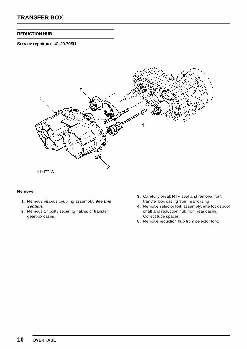
REDUCTION HUB
Service repair no - 41.20.70/01
Remove
1. Remove viscous coupling assembly. See thissection.
2. Remove 17 bolts securing halves of transfergearbox casing.
3. Carefully break RTV seal and remove fronttransfer box casing from rear casing.
4. Remove selector fork assembly, interlock spoolshaft and reduction hub from rear casing.Collect tube spacer.
5. Remove reduction hub from selector fork.

TRANSFER BOX
OVERHAUL 11
Refit
1. Clean RTV sealant from front and rear casingmating surfaces.
CAUTION: Do not use a metal scraper asthis may damage sealing surfaces.
2. Fit reduction hub to selector fork with hubsplines towards the shorter end of shift rail.
3. Fit tube spacer to interlock spool shaft.4. Engage selector fork cam follower to interlock
spool cam track.5. Fit reduction hub to intermediate shaft and
engage interlock spool shaft and shift rail toholes in rear casing.
6. Rotate interlock spool shaft to positionreduction hub and selector fork to low ratioposition, nearest rear casing half. Ensure tubespacer is in position and selector fork camfollower is correctly engaged to interlock spool.
7. If removed, fit 2 dowels to front casing.8. Apply a continuous 2 mm bead of RTV sealant
to rear casing mating face. Path to be aroundinside of bolt holes.
9. Fit front casing to rear casing, ensure boltholes and dowels are aligned before disturbingRTV sealant.
10. Fit bolts securing front casing to rear casingand progressively tighten to 35 Nm. (26 lbf.ft)
11. Check freedom of rotation of input shaft andthat rear output shaft rotates.
12. Fit viscous coupling assembly. See thissection.
TRANSFER BOX
12 OVERHAUL
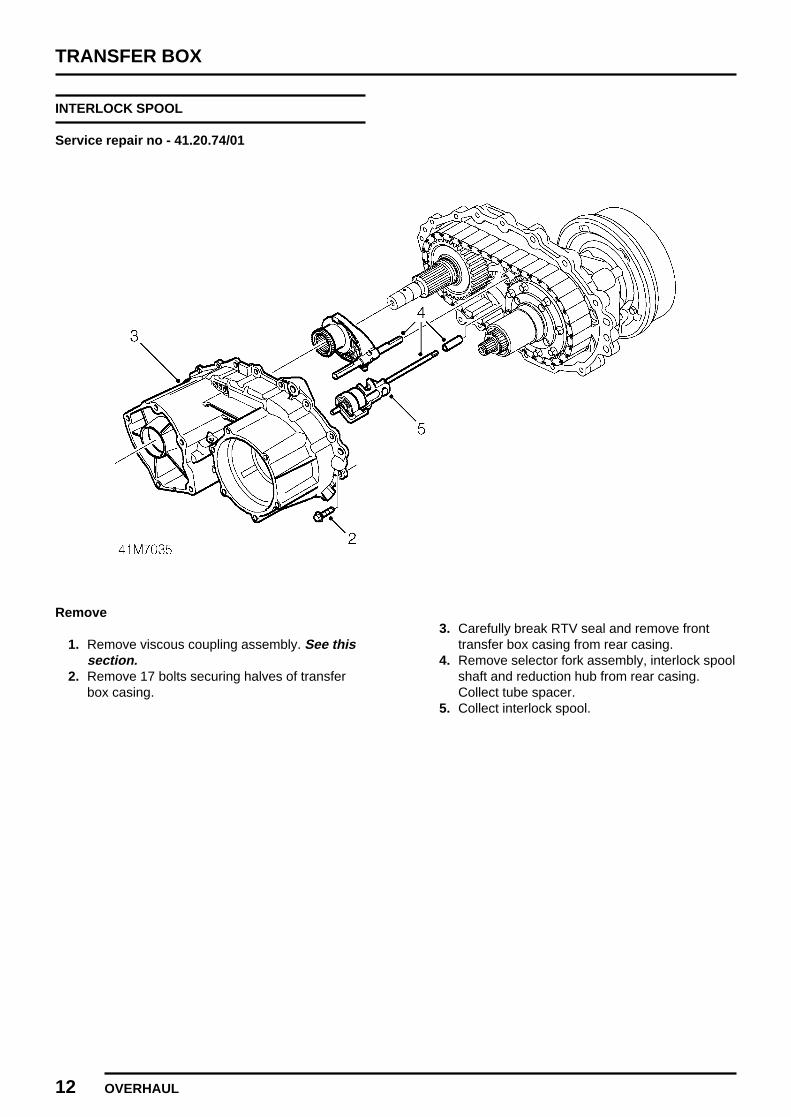
INTERLOCK SPOOL
Service repair no - 41.20.74/01
Remove
1. Remove viscous coupling assembly. See thissection.
2. Remove 17 bolts securing halves of transferbox casing.
3. Carefully break RTV seal and remove fronttransfer box casing from rear casing.
4. Remove selector fork assembly, interlock spoolshaft and reduction hub from rear casing.Collect tube spacer.
5. Collect interlock spool.

TRANSFER BOX
OVERHAUL 13
Refit
1. Clean RTV sealant from front and rear casingmating surfaces.
CAUTION: Do not use a metal scraper asthis may damage sealing surfaces.
2. Fit tube spacer to interlock spool shaft.3. Engage selector fork cam follower to interlock
spool cam track.4. Fit reduction hub to intermediate shaft and
engage interlock spool shaft and shift rail toholes in rear casing.
5. Rotate interlock spool shaft to positionreduction hub and selector fork to low ratioposition, nearest rear casing half. Ensure tubespacer is in position and selector fork camfollower is correctly engaged in interlock spool.
6. If removed, fit 2 dowels into front casing.7. Apply a continuous 2 mm bead of RTV sealant
to rear casing mating face. Path to be aroundinside of bolt holes.
8. Fit front casing to rear casing, ensure boltholes and dowels are aligned before disturbingRTV sealant.
9. Fit bolts securing front casing to rear casingand progressively tighten to 35 Nm. (26 lbf.ft)
10. Check freedom of rotation of input shaft andthat rear output shaft rotates.
11. Fit viscous coupling assembly. See thissection.
TRANSFER BOX
14 OVERHAUL
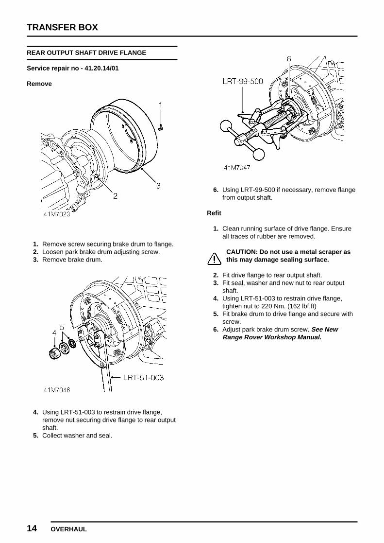
REAR OUTPUT SHAFT DRIVE FLANGE
Service repair no - 41.20.14/01
Remove
1. Remove screw securing brake drum to flange.2. Loosen park brake drum adjusting screw.3. Remove brake drum.
4. Using LRT-51-003 to restrain drive flange,remove nut securing drive flange to rear outputshaft.
5. Collect washer and seal.
6. Using LRT-99-500 if necessary, remove flangefrom output shaft.
Refit
1. Clean running surface of drive flange. Ensureall traces of rubber are removed.
CAUTION: Do not use a metal scraper asthis may damage sealing surface.
2. Fit drive flange to rear output shaft.3. Fit seal, washer and new nut to rear output
shaft.4. Using LRT-51-003 to restrain drive flange,
tighten nut to 220 Nm. (162 lbf.ft)5. Fit brake drum to drive flange and secure with
screw.6. Adjust park brake drum screw. See New
Range Rover Workshop Manual.
TRANSFER BOX
OVERHAUL 15
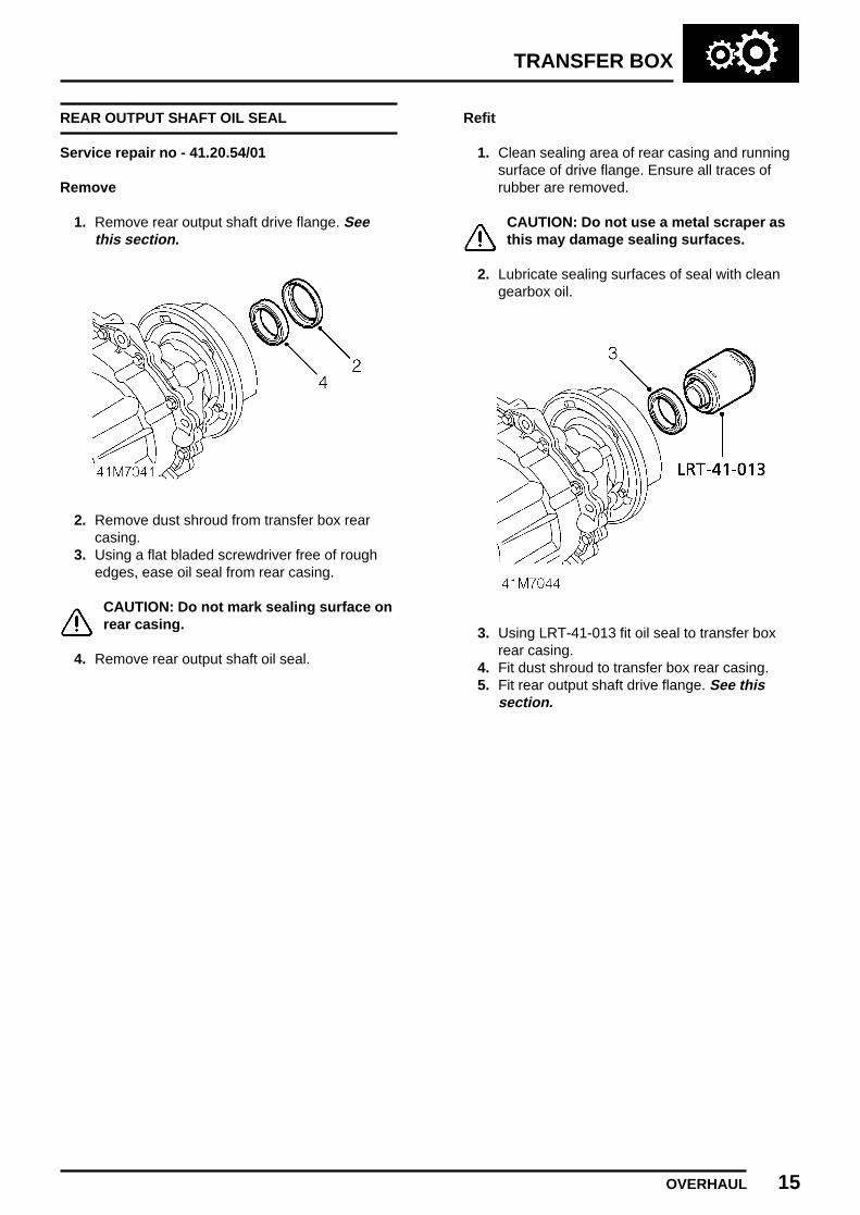
REAR OUTPUT SHAFT OIL SEAL
Service repair no - 41.20.54/01
Remove
1. Remove rear output shaft drive flange. Seethis section.
2. Remove dust shroud from transfer box rearcasing.
3. Using a flat bladed screwdriver free of roughedges, ease oil seal from rear casing.
CAUTION: Do not mark sealing surface onrear casing.
4. Remove rear output shaft oil seal.
Refit
1. Clean sealing area of rear casing and runningsurface of drive flange. Ensure all traces ofrubber are removed.
CAUTION: Do not use a metal scraper asthis may damage sealing surfaces.
2. Lubricate sealing surfaces of seal with cleangearbox oil.
3. Using LRT-41-013 fit oil seal to transfer boxrear casing.
4. Fit dust shroud to transfer box rear casing.5. Fit rear output shaft drive flange. See this
section.

TRANSFER BOX
16 OVERHAUL
DRIVE CHAIN
Service repair no - 41.20.67/01
Remove
1. Remove rear output shaft drive flange. Seethis section.
2. Remove interlock spool. See this section.
3. Release differential assembly from rear casinguntil differential rear bearing is clear of casing.
NOTE: Ensure rear output drive shaftmoves with differential.
4. Tilt differential assembly towards drivesprocket, take care not to bruise casing.
5. Remove drive chain from gears.6. Position differential assembly to rest in rear
casing.
Refit
1. Position differential assembly towards drivegear and fit drive chain to both gears.
2. Engage chain to gears and align differentialrear bearing to rear casing.
3. Engage differential rear bearing to rear casingand output shaft to output shaft bearing.
4. Fit interlock spool. See this section.5. Fit rear output shaft drive flange. See this
section.

TRANSFER BOX
OVERHAUL 17
DIFFERENTIAL UNIT
Service repair no - 41.20.13/01
Remove
1. Remove drive chain. See this section.
2. Remove differential unit from rear output shaft.
Refit
1. Fit differential unit to rear output shaft.2. Fit drive chain. See this section.
DIFFERENTIAL BEARINGS
Service repair no - 41.20.17/01
Remove
1. Remove differential unit from transfer box. Seethis section.
2. Using a suitable puller, remove 2 bearings fromdifferential unit.
Refit
1. Ensure bearing and differential mating facesare clean.
2. Press bearings onto differential unit.3. Fit differential unit to transfer box. See this
section.
TRANSFER BOX
18 OVERHAUL
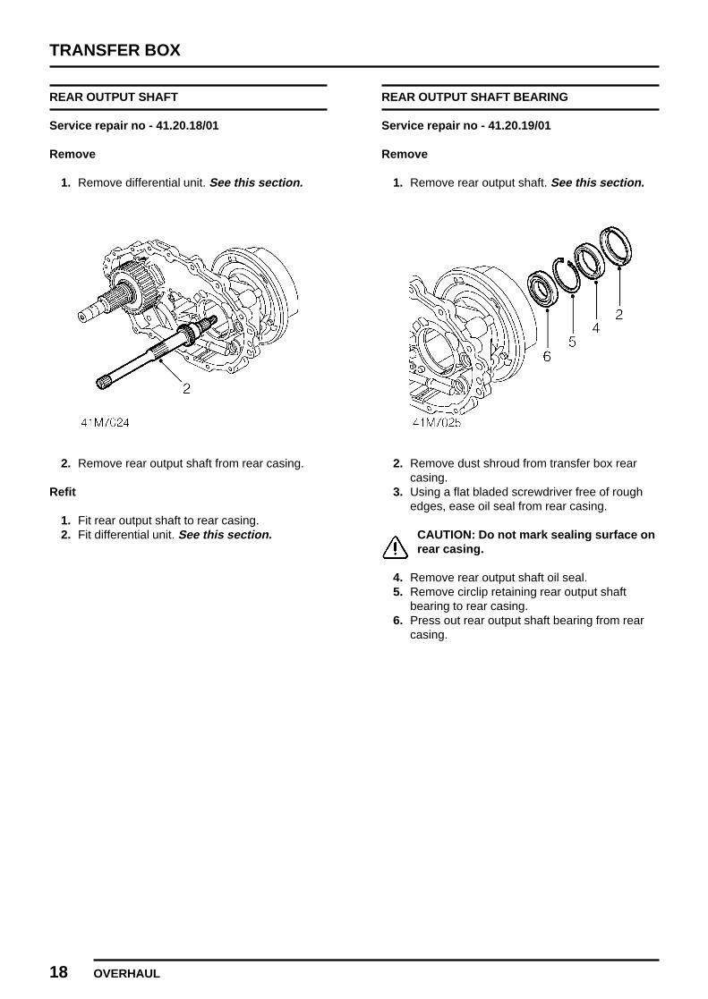
REAR OUTPUT SHAFT
Service repair no - 41.20.18/01
Remove
1. Remove differential unit. See this section.
2. Remove rear output shaft from rear casing.
Refit
1. Fit rear output shaft to rear casing.2. Fit differential unit. See this section.
REAR OUTPUT SHAFT BEARING
Service repair no - 41.20.19/01
Remove
1. Remove rear output shaft. See this section.
2. Remove dust shroud from transfer box rearcasing.
3. Using a flat bladed screwdriver free of roughedges, ease oil seal from rear casing.
CAUTION: Do not mark sealing surface onrear casing.
4. Remove rear output shaft oil seal.5. Remove circlip retaining rear output shaft
bearing to rear casing.6. Press out rear output shaft bearing from rear
casing.
TRANSFER BOX
OVERHAUL 19
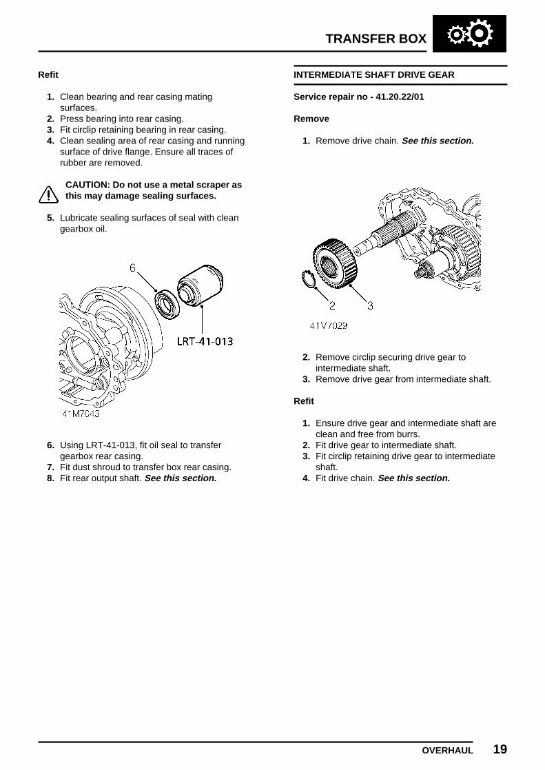
Refit
1. Clean bearing and rear casing matingsurfaces.
2. Press bearing into rear casing.3. Fit circlip retaining bearing in rear casing.4. Clean sealing area of rear casing and running
surface of drive flange. Ensure all traces ofrubber are removed.
CAUTION: Do not use a metal scraper asthis may damage sealing surfaces.
5. Lubricate sealing surfaces of seal with cleangearbox oil.
6. Using LRT-41-013, fit oil seal to transfergearbox rear casing.
7. Fit dust shroud to transfer box rear casing.8. Fit rear output shaft. See this section.
INTERMEDIATE SHAFT DRIVE GEAR
Service repair no - 41.20.22/01
Remove
1. Remove drive chain. See this section.
2. Remove circlip securing drive gear tointermediate shaft.
3. Remove drive gear from intermediate shaft.
Refit
1. Ensure drive gear and intermediate shaft areclean and free from burrs.
2. Fit drive gear to intermediate shaft.3. Fit circlip retaining drive gear to intermediate
shaft.4. Fit drive chain. See this section.
TRANSFER BOX
20 OVERHAUL
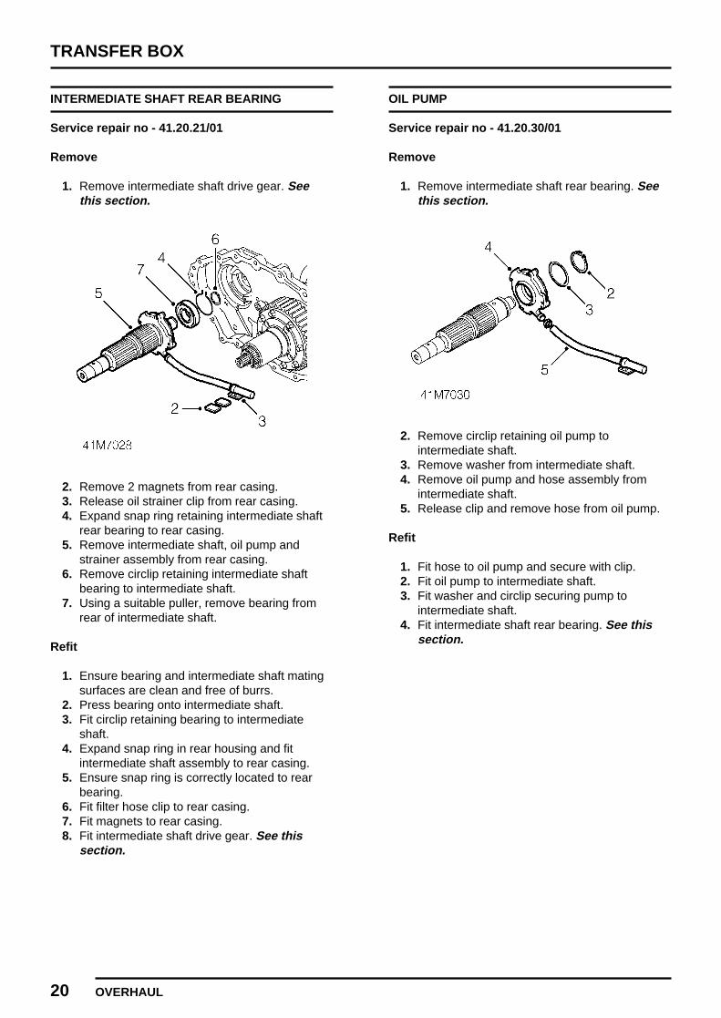
INTERMEDIATE SHAFT REAR BEARING
Service repair no - 41.20.21/01
Remove
1. Remove intermediate shaft drive gear. Seethis section.
2. Remove 2 magnets from rear casing.3. Release oil strainer clip from rear casing.4. Expand snap ring retaining intermediate shaft
rear bearing to rear casing.5. Remove intermediate shaft, oil pump and
strainer assembly from rear casing.6. Remove circlip retaining intermediate shaft
bearing to intermediate shaft.7. Using a suitable puller, remove bearing from
rear of intermediate shaft.
Refit
1. Ensure bearing and intermediate shaft matingsurfaces are clean and free of burrs.
2. Press bearing onto intermediate shaft.3. Fit circlip retaining bearing to intermediate
shaft.4. Expand snap ring in rear housing and fit
intermediate shaft assembly to rear casing.5. Ensure snap ring is correctly located to rear
bearing.6. Fit filter hose clip to rear casing.7. Fit magnets to rear casing.8. Fit intermediate shaft drive gear. See this
section.
OIL PUMP
Service repair no - 41.20.30/01
Remove
1. Remove intermediate shaft rear bearing. Seethis section.
2. Remove circlip retaining oil pump tointermediate shaft.
3. Remove washer from intermediate shaft.4. Remove oil pump and hose assembly from
intermediate shaft.5. Release clip and remove hose from oil pump.
Refit
1. Fit hose to oil pump and secure with clip.2. Fit oil pump to intermediate shaft.3. Fit washer and circlip securing pump to
intermediate shaft.4. Fit intermediate shaft rear bearing. See this
section.

TRANSFER BOX
OVERHAUL 21
INTERMEDIATE SHAFT
Service repair no - 41.20.20/01
Remove
1. Remove oil pump. See this section.
2. Remove circlip from intermediate shaft.
Refit
1. Fit circlip to intermediate shaft.2. Fit oil pump. See this section.
TRANSFER BOX
DATA, TORQUE & TOOLS 1
TORQUE SETTINGS
Output shaft drive flange nut 220 Nm. (162 lbf.ft). . . . . . . . . . . . . . . . . . .Front gearcase to rear gearcase bolts 35 Nm. (26 lbf.ft). . . . . . . . . . . .VCU housing to gearcase bolts 35 Nm. (26 lbf.ft). . . . . . . . . . . . . . . . .Speed sensor 30 Nm. (22 lbf.ft). . . . . . . . . . . . . . . . . . . . . . . . . . . . . .Drain/Refill plugs 25 Nm. (18 lbf.ft). . . . . . . . . . . . . . . . . . . . . . . . . . . .Temperature sensor 15 Nm. (11 lbf.ft). . . . . . . . . . . . . . . . . . . . . . . . .Ratio control motor to gearcase bolts 10 Nm. (7 lbf.ft). . . . . . . . . . . .Breather hose 10 Nm. (7 lbf.ft). . . . . . . . . . . . . . . . . . . . . . . . . . . . . .
TOOL NUMBERS
LRT 41 011 Input shaft oil seal replacer. . . . . . . . . . . . . . . . . . . . . . . . . . . . . . . .LRT 41 013 Output shaft oil seal replacer. . . . . . . . . . . . . . . . . . . . . . . . . . . . . . . .LRT 51 003 Drive flange restraining tool. . . . . . . . . . . . . . . . . . . . . . . . . . . . . . . .LRT 99 500 Drive flange puller. . . . . . . . . . . . . . . . . . . . . . . . . . . . . . . .