bond strength of steel bar and plain or fibre reinforced ...€¦ · bond strength of steel bar and...
TRANSCRIPT
Bond Strength of Steel Bar and Plain or Fibre Reinforced Geopolymer Concrete
Yifei Cui1) , Obada Kayali2) , Tiejun Zhao1) and Chunwei Zhang1)*
1) School of Civil Engineering, Qingdao University of Technology, Qingdao, China
2) School of Engineering and Information Technology, UNSW,Australia
ABSTRACT
Fly ash based geopolymer concrete (GPC) has been widely regarded as a potential alternative to Ordinary Portland-Cement Concrete (OPC) due to its environmentally friendly and comparable mechanical properties. Moreover, the fibre reinforced GPC (FGPC) material has shown superior mechanical performance when compared with fibre reinforced OPC (FOPC). To be used practically in the construction of reinforced structure, GPC and FGPC needed to be confirmed to possess reliable bond with reinforcing bars. Compared to OPC, this alkaline-activated inorganic polymer concrete has a totally different micro structures and hydration process. In this research, to explore and understand GPC’s bond performance, 48 pull-out tests on GPC, OPC, FGPC and FOPC were conducted. The average bond strength values of the four types of concrete with smooth and ribbed bars were determined. The mode of failure and bond strength of the four concrete types were illustrated and compared. The results of this study revealed the significant differences between the bond performance of GPC and OPC, as well as the differences on bond performance between plain GPC and OPC; FGPC and FOPC. It is believed that the strong adhesion between the geopolymer binder and steel bars contributes to the remarkable improvement in the bond with steel bars. 1. INTRODUCTION For decades, concrete manufactured using Portland cement has gradually become the major symbol of modern architecture. Nevertheless, criticism of high pollution in cement production has accompanied its continuous wide use. Production of Portland cement consumes large amounts of natural resources and energy, accompanied by large amounts of greenhouse gas emissions. It is known that to produce one tonne of Portland cement will release nearly one tonne of CO2 into the atmosphere (Gao 2016). With increasing concerns over the environmental damage caused by Portland cement, substitute binders for concrete have been continually researched. Among all the suggested alternative binders, geopolymers stand out because of their environmental
friendliness, good engineering performance and inexpensive processing costs (Davidovits 1994, Mandal 2014). Different from ordinary Portland cement concrete (OPC), geopolymer concretes (GPC) are members of inorganic polymer composites. The raw material commonly used to produce geopolymers is fly ash, an important by-product in power generation industries. A Fly-ash based geopolymer is synthesized by activating fly ash with alkaline activators, which transform the glassy structures of fly-ash into very compact well-cemented composites (Hardjito 2005, Ramujee 2017). The chemical structure of alkaline-activated fly-ash geopolymer provides it with many outstanding engineering characteristics. The spherical shape of fly ash often helps to improve the workability of fresh concrete, while it’s small particle size acts as filler of voids, hence producing dense and durable concrete with better tensile resistance (Van Jaarsveld 2010). It has been shown previously that, in many cases, GPC even outperforms ordinary OPC concrete with respect to compressive strength and bending resistance (Ramujee 2017). The development of fibre reinforced GPC has been accompanying with the application of geopolymer composites. It has been reported that (Shakih 2016) This study focuses on the bond of GPC with reinforcing bars. Bond is the interaction between reinforcing steel and surrounding concrete. When concrete structural components are subjected to loads, the stresses are transferred from the concrete to the reinforcing bars by the bond at their surface (Tepfers 1979). The force transfer from concrete to steel can be attributed to three different phenomena: 1) Chemical adhesion between mortar paste and bar surface. The magnitudes of adhesion force depend on the chemical reaction at the interface of concrete and steel. 2) Friction and wedging action of small dislodged particles between the bar and the surrounding concrete. The friction force is determined by the surface roughness condition. 3) Mechanical interaction between concrete and steel (Kayali 2004). When the pull-out force is applied to ribbed reinforcement, the lugs push the concrete in front of them, and in this way most of the force is transferred through the lugs to concrete (Lee, 2016). Compared with this bearing force, friction and chemical adhesion forces are secondary and tend to decrease quickly as the reinforcing bars start to slip.That is why the bond performance of ribbed bars is significantly better than plain bars in bond strength tests. Design provisions of reinforced concrete are based on the theory that concrete and steel work as one integral unit. This integration that allows designers to treat reinforced concrete as a composite material is contributed by the bond strength between concrete and steel. To be used in practical reinforced concrete construction, GPC and FGPC must be proved to bond well with reinforcement to provide at least similar integration as OPC. The study discussed here is primarily to determine the bond performance of GPC. The commonly used pull-out test is chosen to test the bond strength between concrete and reinforcing steel. Comparisons are made between the bond strength of GPC, OPC, Fibre reinforced GPC (FGPC), and Fibre reinforced OPC(FOPC).

2. Experimental 2.1 Materials and Manufacture of Samples
2.1.1 Concrete In this study, GPC, OPC, FGPC and FOPC four different mixes were made in the laboratory using a 120L concrete mixer. The OPC mix was designed according to British method(BRE 1993) while the GPC mix design are based on Junaid’s design method (Junaid 2012).The mix proportions of the four mixes are given in Table 1.
Table 1. Mix proportion of concrete (kg/m3).
Ingredients GPC OPC FGPC FOPC
14mm aggregate
500 242
495 235.8
10 mm aggregate
310 458
306 424
7 mm aggregate
280 349
277 340
Fine aggregate 630 758 630 758
Class F Fly Ash
420 -
420 -
Cement - 357 - 357
12mol/L NaOH 60 - 60 -
Na2SiO3 150 - 150 -
Water 25.9 225 25.9 225
SP 4 - 4 -
VM 4 - 4 -
Steel fibre 0 0 79 79
Note: The fibre content for FGPC and FOPC is 1% by volume (The fibre used in this work is 12mm copper coated steel fibre, whose aspect ratio and tensile strength are 65 MPa and 2500 MPa, respectively) ASTM Class F Fly ash was used as the raw material for the geopolymer. The alkaline liquid used was a combination of sodium hydroxide and sodium silicate solutions. Laboratory grade D sodium silicate solution (Na2SiO3) with SiO2/Na2O between 1.95 and 2.05 was procured from IMCD Australia Limited) (Talha, 2012). The sodium hydroxide solution was of 12 M concentration and was made from dissolving commercial 98% purity flakes (supplied by Redox Pyt Ltd., Australia) in water. 14mm, 10mm and 7mm crushed coarse aggregates are prepared to saturated surface-dry
condition before mixing. Two kinds of superplasticizer (CENTROXTM HWR and
CENTROXTM VM, both were used at the dosage rate of 900 mL per 100kg of binder
materials)and tap water were also added to improve the workability of geopolymer
concrete.

2.1.2 Steel The reinforcing steel bars are Australian normal ductility hot-rolled ribbed bars from One Steel. Samples of steel bars were tested in the laboratory to obtain the actual yield and ultimate strength values. These results are given in Table 4.
Table 4. Properties of Test bars.
Steel Bars Diameter (mm)
Nominal area (mm2)
Yield strength (Mpa)
Ultimate strength (Mpa)
Ribbed bar 16 201 546 633
Plain bar 16 201 339 507
2.1.3 Manufacture of samples
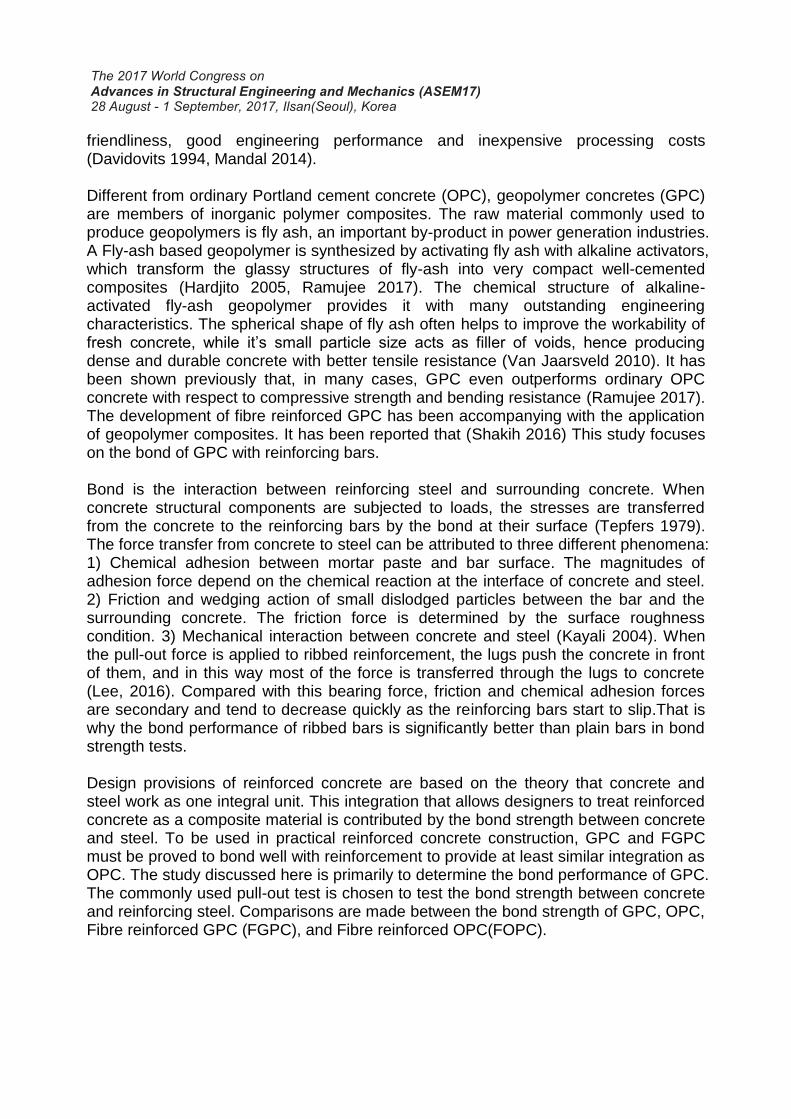
The manufacturing of geopolymer concrete was similar to that of OPC concrete. All the specimens were cast vertically with the steel bars accurately secured in the middle of the moulds. The concrete was vibrated with a standard electrical pencil vibrator. Each mix was cast into12 lollipop samples and nine 100 mm x 200 mm cylinders for compressive and tensile strength tests of the concrete. After casting, all the OPC concrete specimens were demoulded at 24 hours and then subjected to moist curing for 27 days. In contrast, all the GPC samples were left for 24 hours (resting time) and then transferred to an oven for 72 hours heat curing at 80°C. After heating the GPC specimens were then de-moulded and left at ambient temperature until the time of testing. Unlike OPC concrete which is usually tested at 28 days after casting, GPC could reach its relatively full strength much quicker. So the mechanical tests were conducted at 7 days after curing. The compressive strength of GPC and FGPC samples were tested according to the respective Australian Standards. 2.2 Pull-out Test Specimens To test the bond quality of GPC and FGPC, 24 lollipop-like pull-out specimens were cast – 12 specimens consisted of the standard GPC and the remaining 12 specimens were FGPC. The test specimens consisted of pull-out concrete cylinders with centrally placed reinforcing bars. Six plain bars and six ribbed bars were cast into the GPC samples and an identical number of plain and ribbed bars were embedded into the FGPC samples. Each subgroup (GPC-Plain, GPC-Ribbed, FGPC-Plain, FGPC-Ribbed) consisted of 2 different embedment lengths – 120mm and 150mm (i.e. 3x GPC-Plain bars at 120mm and 3x GPC-Plain at 150mm). When casting these samples, the embedment length of the bars was controlled by placing PVC pipes onto two positions of the bar such that the bonded part of the bar is accurately known and located away from the specimen’s ends. This arrangement ensured de-bonding between the steel and concrete. The bond strength values of these samples was then determined and compared. Controlled trials were conducted to compare the bond behaviour of the GPC/FGPC samples with an equal number of OPC/FOPC samples. The dimensions of the cylinders were 140 mm high and 100 mm in diameter for 120mm bond length samples;
and 170 mm high and 100mm in diameter for 150mm bond length samples as shown in Figure 1.
Figure 1. Geometry of Lollipop specimens.
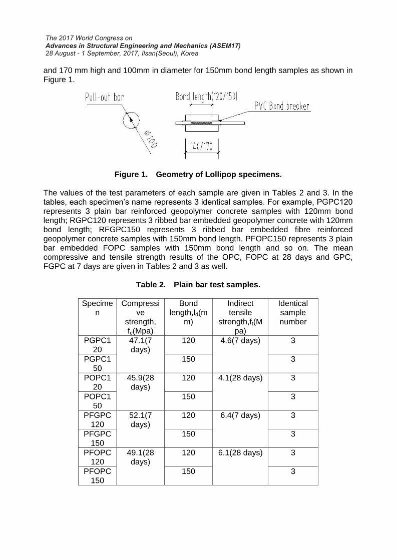
The values of the test parameters of each sample are given in Tables 2 and 3. In the tables, each specimen’s name represents 3 identical samples. For example, PGPC120 represents 3 plain bar reinforced geopolymer concrete samples with 120mm bond length; RGPC120 represents 3 ribbed bar embedded geopolymer concrete with 120mm bond length; RFGPC150 represents 3 ribbed bar embedded fibre reinforced geopolymer concrete samples with 150mm bond length. PFOPC150 represents 3 plain bar embedded FOPC samples with 150mm bond length and so on. The mean compressive and tensile strength results of the OPC, FOPC at 28 days and GPC, FGPC at 7 days are given in Tables 2 and 3 as well.
Table 2. Plain bar test samples.
Specimen
Compressive
strength, fc(Mpa)
Bond length,ld(m
m)
Indirect tensile
strength,ft(Mpa)
Identical sample number
PGPC120
47.1(7 days)
120 4.6(7 days) 3
PGPC150
150 3
POPC120
45.9(28 days)
120 4.1(28 days) 3
POPC150
150 3
PFGPC120
52.1(7 days)
120 6.4(7 days) 3
PFGPC150
150 3
PFOPC120
49.1(28 days)
120 6.1(28 days) 3
PFOPC150
150 3
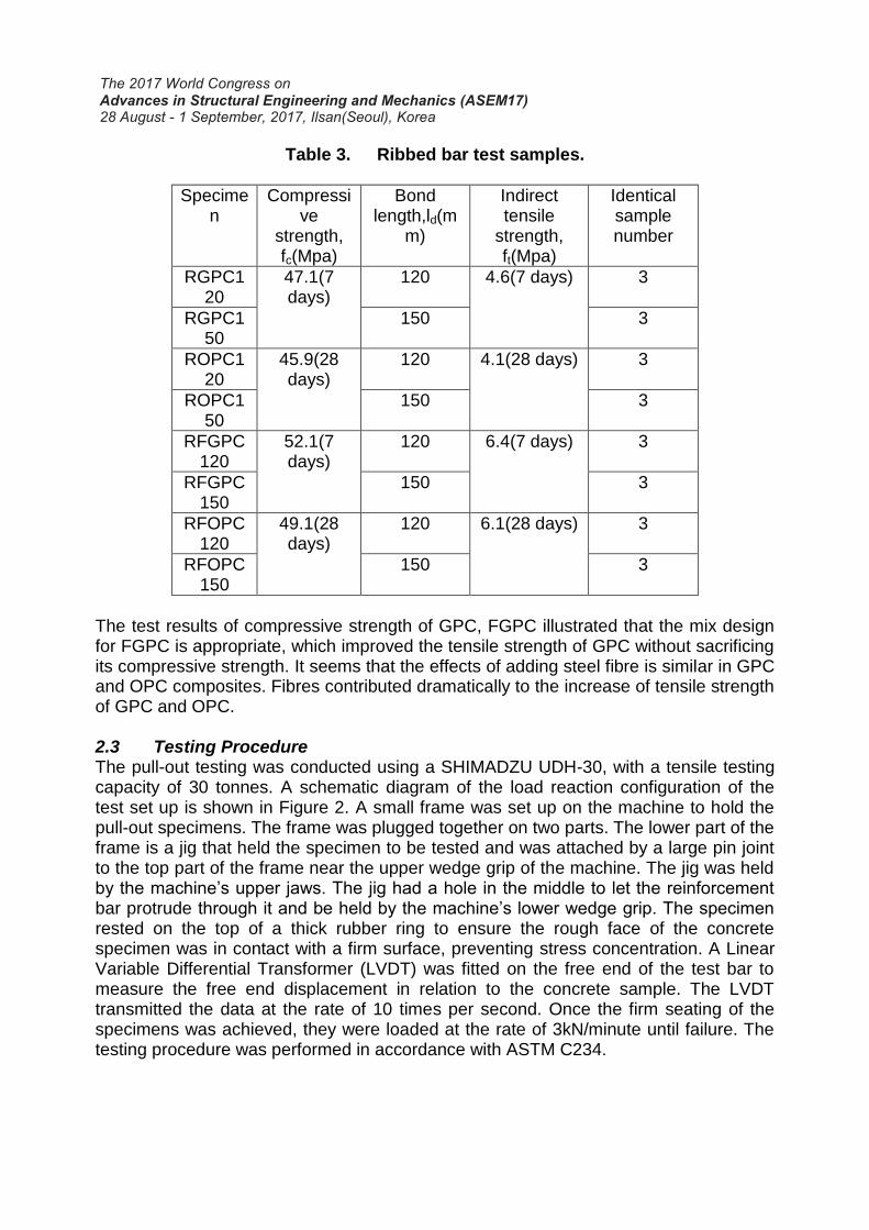
Table 3. Ribbed bar test samples.
Specimen
Compressive
strength, fc(Mpa)
Bond length,ld(m
m)
Indirect tensile
strength, ft(Mpa)
Identical sample number
RGPC120
47.1(7 days)
120 4.6(7 days) 3
RGPC150
150 3
ROPC120
45.9(28 days)
120 4.1(28 days) 3
ROPC150
150 3
RFGPC120
52.1(7 days)
120 6.4(7 days) 3
RFGPC150
150 3
RFOPC120
49.1(28 days)
120 6.1(28 days) 3
RFOPC150
150 3
The test results of compressive strength of GPC, FGPC illustrated that the mix design for FGPC is appropriate, which improved the tensile strength of GPC without sacrificing its compressive strength. It seems that the effects of adding steel fibre is similar in GPC and OPC composites. Fibres contributed dramatically to the increase of tensile strength of GPC and OPC. 2.3 Testing Procedure The pull-out testing was conducted using a SHIMADZU UDH-30, with a tensile testing capacity of 30 tonnes. A schematic diagram of the load reaction configuration of the test set up is shown in Figure 2. A small frame was set up on the machine to hold the pull-out specimens. The frame was plugged together on two parts. The lower part of the frame is a jig that held the specimen to be tested and was attached by a large pin joint to the top part of the frame near the upper wedge grip of the machine. The jig was held by the machine’s upper jaws. The jig had a hole in the middle to let the reinforcement bar protrude through it and be held by the machine’s lower wedge grip. The specimen rested on the top of a thick rubber ring to ensure the rough face of the concrete specimen was in contact with a firm surface, preventing stress concentration. A Linear Variable Differential Transformer (LVDT) was fitted on the free end of the test bar to measure the free end displacement in relation to the concrete sample. The LVDT transmitted the data at the rate of 10 times per second. Once the firm seating of the specimens was achieved, they were loaded at the rate of 3kN/minute until failure. The testing procedure was performed in accordance with ASTM C234.

Figure 2. Schematic view of direct pull-out test setup.
3. Experimental results and discussion The failure mode of the different samples, and the different bond strength values of the different types of concrete and bars were observed and the results may be summarized as follows. 3.1 Failure of the test specimens
3.1.1 Pullout failure All plain bar embedded lollipop specimens failed by the bar pulling out of the concrete matrix. The pull-out procedure could last a long time and result in a very large displacement. So the maximum failure load was defined as being the load when displacement recorded by the LVDT reached 200 microns. The failed samples did not show obvious cracks on the surface. As shown in Figure 3, the four types of concrete tested samples still kept their integrity.
Figure 3. The test apparatus of lollipop pull-out test.
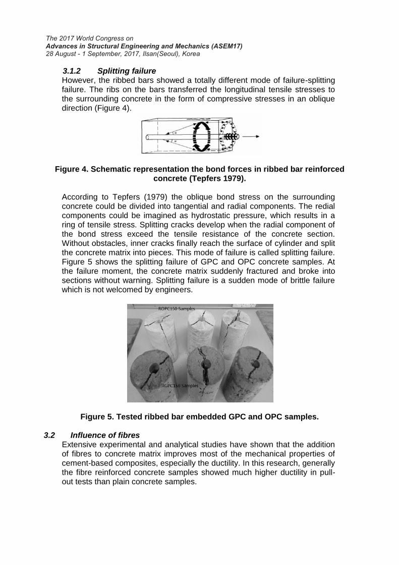
3.1.2 Splitting failure However, the ribbed bars showed a totally different mode of failure-splitting failure. The ribs on the bars transferred the longitudinal tensile stresses to the surrounding concrete in the form of compressive stresses in an oblique direction (Figure 4).
Figure 4. Schematic representation the bond forces in ribbed bar reinforced concrete (Tepfers 1979).
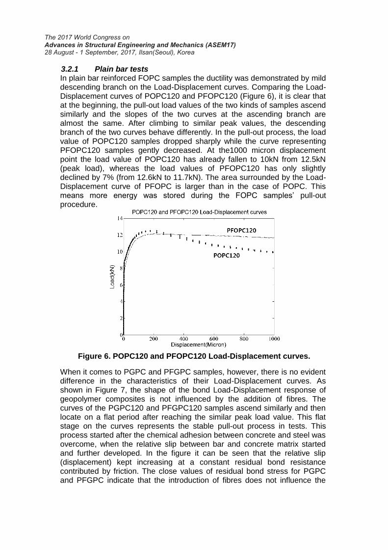
According to Tepfers (1979) the oblique bond stress on the surrounding concrete could be divided into tangential and radial components. The redial components could be imagined as hydrostatic pressure, which results in a ring of tensile stress. Splitting cracks develop when the radial component of the bond stress exceed the tensile resistance of the concrete section. Without obstacles, inner cracks finally reach the surface of cylinder and split the concrete matrix into pieces. This mode of failure is called splitting failure. Figure 5 shows the splitting failure of GPC and OPC concrete samples. At the failure moment, the concrete matrix suddenly fractured and broke into sections without warning. Splitting failure is a sudden mode of brittle failure which is not welcomed by engineers.
Figure 5. Tested ribbed bar embedded GPC and OPC samples.
3.2 Influence of fibres Extensive experimental and analytical studies have shown that the addition of fibres to concrete matrix improves most of the mechanical properties of cement-based composites, especially the ductility. In this research, generally the fibre reinforced concrete samples showed much higher ductility in pull-out tests than plain concrete samples.
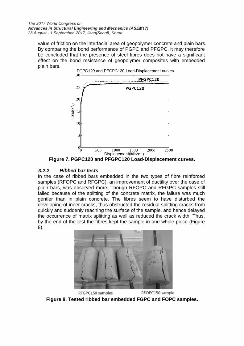
3.2.1 Plain bar tests In plain bar reinforced FOPC samples the ductility was demonstrated by mild descending branch on the Load-Displacement curves. Comparing the Load-Displacement curves of POPC120 and PFOPC120 (Figure 6), it is clear that at the beginning, the pull-out load values of the two kinds of samples ascend similarly and the slopes of the two curves at the ascending branch are almost the same. After climbing to similar peak values, the descending branch of the two curves behave differently. In the pull-out process, the load value of POPC120 samples dropped sharply while the curve representing PFOPC120 samples gently decreased. At the1000 micron displacement point the load value of POPC120 has already fallen to 10kN from 12.5kN (peak load), whereas the load values of PFOPC120 has only slightly declined by 7% (from 12.6kN to 11.7kN). The area surrounded by the Load-Displacement curve of PFOPC is larger than in the case of POPC. This means more energy was stored during the FOPC samples’ pull-out procedure.
Figure 6. POPC120 and PFOPC120 Load-Displacement curves.
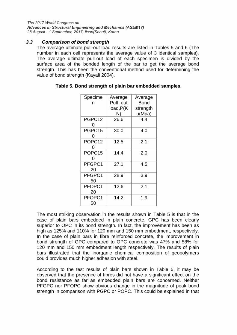
When it comes to PGPC and PFGPC samples, however, there is no evident difference in the characteristics of their Load-Displacement curves. As shown in Figure 7, the shape of the bond Load-Displacement response of geopolymer composites is not influenced by the addition of fibres. The curves of the PGPC120 and PFGPC120 samples ascend similarly and then locate on a flat period after reaching the similar peak load value. This flat stage on the curves represents the stable pull-out process in tests. This process started after the chemical adhesion between concrete and steel was overcome, when the relative slip between bar and concrete matrix started and further developed. In the figure it can be seen that the relative slip (displacement) kept increasing at a constant residual bond resistance contributed by friction. The close values of residual bond stress for PGPC and PFGPC indicate that the introduction of fibres does not influence the
value of friction on the interfacial area of geopolymer concrete and plain bars. By comparing the bond performance of PGPC and PFGPC, it may therefore be concluded that the presence of steel fibres does not have a significant effect on the bond resistance of geopolymer composites with embedded plain bars.
Figure 7. PGPC120 and PFGPC120 Load-Displacement curves.
3.2.2 Ribbed bar tests In the case of ribbed bars embedded in the two types of fibre reinforced samples (RFOPC and RFGPC), an improvement of ductility over the case of plain bars, was observed more. Though RFOPC and RFGPC samples still failed because of the splitting of the concrete matrix, the failure was much gentler than in plain concrete. The fibres seem to have disturbed the developing of inner cracks, thus obstructed the residual splitting cracks from quickly and suddenly reaching the surface of the sample, and hence delayed the occurrence of matrix splitting as well as reduced the crack width. Thus, by the end of the test the fibres kept the sample in one whole piece (Figure 8).
Figure 8. Tested ribbed bar embedded FGPC and FOPC samples.
3.3 Comparison of bond strength The average ultimate pull-out load results are listed in Tables 5 and 6 (The number in each cell represents the average value of 3 identical samples). The average ultimate pull-out load of each specimen is divided by the surface area of the bonded length of the bar to get the average bond strength. This has been the conventional method used for determining the value of bond strength (Kayali 2004).
Table 5. Bond strength of plain bar embedded samples.
Specimen
Average Pull -out load,P(K
N)
Average Bond
strength u(Mpa)
PGPC120
26.6 4.4
PGPC150
30.0 4.0
POPC120
12.5 2.1
POPC150
14.4 2.0
PFGPC120
27.1 4.5
PFGPC150
28.9 3.9
PFOPC120
12.6 2.1
PFOPC150
14.2 1.9
The most striking observation in the results shown in Table 5 is that in the case of plain bars embedded in plain concrete, GPC has been clearly superior to OPC in its bond strength. In fact, the improvement has been as high as 125% and 110% for 120 mm and 150 mm embedment, respectively. In the case of plain bars in fibre reinforced concrete, the improvement in bond strength of GPC compared to OPC concrete was 47% and 58% for 120 mm and 150 mm embedment length respectively. The results of plain bars illustrated that the inorganic chemical composition of geopolymers could provides much higher adhesion with steel. According to the test results of plain bars shown in Table 5, it may be observed that the presence of fibres did not have a significant effect on the bond resistance as far as embedded plain bars are concerned. Neither PFGPC nor PFOPC show obvious change in the magnitude of peak bond strength in comparison with PGPC or POPC. This could be explained in that
before the appearance of relative slip, the bond resistance between plain bar and concrete is mainly attributed to the chemical adhesion between concrete and steel bars. The magnitude of chemical adhesion is dependent on the chemical composition on the interfacial area between concrete and steel. Adding fibres into the concrete is not expected to influence the chemical composition of the interface. Another observed result, as shown in the Table is that, the ultimate loading has increased when changing the embedment length from 120mm to 150mm, yet the average bond strength values calculated from the traditional way (simply by dividing the load by the cylindrical area) have reduced. This is not expected, as the bond strength is one of the properties that are expected to be irrelevant to embedment length. This observation may lead to the conclusion that the traditional calculation method for bond strength is imprecise in the case of plain bars. Other factors beyond the scope of this paper must also be influencing this behavior.
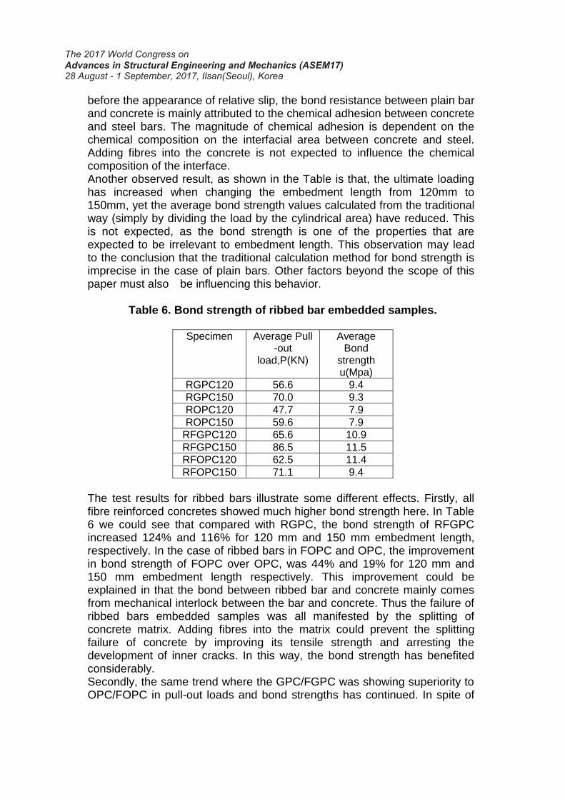
Table 6. Bond strength of ribbed bar embedded samples.
Specimen Average Pull
-out load,P(KN)
Average Bond
strength u(Mpa)
RGPC120 56.6 9.4
RGPC150 70.0 9.3
ROPC120 47.7 7.9
ROPC150 59.6 7.9
RFGPC120 65.6 10.9
RFGPC150 86.5 11.5
RFOPC120 62.5 11.4
RFOPC150 71.1 9.4
The test results for ribbed bars illustrate some different effects. Firstly, all fibre reinforced concretes showed much higher bond strength here. In Table 6 we could see that compared with RGPC, the bond strength of RFGPC increased 124% and 116% for 120 mm and 150 mm embedment length, respectively. In the case of ribbed bars in FOPC and OPC, the improvement in bond strength of FOPC over OPC, was 44% and 19% for 120 mm and 150 mm embedment length respectively. This improvement could be explained in that the bond between ribbed bar and concrete mainly comes from mechanical interlock between the bar and concrete. Thus the failure of ribbed bars embedded samples was all manifested by the splitting of concrete matrix. Adding fibres into the matrix could prevent the splitting failure of concrete by improving its tensile strength and arresting the development of inner cracks. In this way, the bond strength has benefited considerably. Secondly, the same trend where the GPC/FGPC was showing superiority to OPC/FOPC in pull-out loads and bond strengths has continued. In spite of
the improvement being much less significant than that seen in the plain bars case, it should be pointed out that here the effective contribution to bond strength comes largely from the ribs. The improvement in the bond strength of GPC/FGPC compared to that of OPC/FOPC could be explained by the higher splitting tensile strength of GPC/FGPC at similar compressive strength (As shown in Tables 2 and 3). The increase in tensile strength has delayed the splitting failure of the fibre reinforced concrete samples. Thirdly, it is also noticeable that, unlike plain bars, the average bond strength values calculated using the traditional method are more or less the same for different embedment lengths. In other words, the calculations of bond strength are more reliable here. It therefore seems, that when the ribs are involved, the factors influencing the accuracy of bond strength calculations of plain bars, become insignificant compared to the effect of the ribs.
3.4 Micro explanation The very different bond behavior of bond between GPC and OPC could be explained by the different microstructures at the bond interfaces. For reference to the microstructure of intimate contact surface between OPC and steel, compressive reviews are available and, in the former contributions, concerns have been solely directed to crystal structures formed at the interfacial layer.Compare with the bulk, the interfacial zone between steel and OPC has quite unique characteristics in the form of higher prosity and larger crystals (Obada 2004).There is formed a dense layer consisting largely of hexagonal lamellar crystals of calcium hydroxide(portlandite) (Lee 2016) and needlelike hydrous calcium aluminium sulfate (ettringite).
4. Conclusions This study has investigated the bond strength of plain geopolymer concrete and fibre reinforced geopolymer concrete. The following conclusions are drawn: Firstly, Geopolymer concrete showed modes of failure similar to those of OPC concrete under pull-out load. Both ribbed bar reinforced GPC and OPC specimens failed in a brittle manner by splitting of concrete along the bonded length of the pull-out bar. Both plain bar reinforced geopolymer and OPC concrete specimens failed in slippage caused by losing adhesion between concrete and steel. Secondly, FGPC showed much higher bond with ribbed bars than plain GPC. However if the bars were smooth, no significant difference was found between these two concrete types. Thirdly, GPC and FGPC both showed higher bond strength with ribbed bars than OPC concrete and FOPC concrete, respectively. This is because of the higher splitting tensile strength of GPC and FGPC compared to their OPC counterparts at similar compressive strength.
Lastly, compared with OPC and FOPC, GPC and FGPC both showed remarkable bond with plain bars. This is believed to be a result of the strong chemical adhesion between the geopolymer binder and steel. 5. Acknowledgement
The research work described in this paper was supported by the project of National Natural Science Foundation of China (51420105015, 51508337); 973 Program (2015CB655100), 111 project; Shenzhen Municipal Commission of Science and Technology and Innovation (JCYJ20150324141711572);Guangdong Provincial Natural Science Foundation (2015A030310129); Natural Science Foundation of Shenzhen University (827000091); Start Project of Shenzhen University (70100037147). 6. References Gao T, Shen L, Shen M, et al.(2016), “Analysis of material flow and consumption in
cement production process”. Journal of Cleaner Production,11 (112):553-565. Davidovits, J. (1994), “High-Alkali cements for 21st century concretes”, ACI Structural
Journal,144(19):383-397. Hardjito, D., Wallah, S.E.et al.( 2005), “Introducing fly ash-based geopolymer concrete:
Manufacture and engineering properties”, 30th conference on 'Our world in concrete and structure', Singapore.
Junaid, M.T., Kayali,O. et al.( 2012), “Mix design procedure for alkali activated fly ash based geopolymer concretes”, Proceedings of 2012 International Conference on Engineering and Applied Science, Beijing, 139-152.
Kayali, O. (2004),“Bond of steel in concrete and effect of galvanizing”, in: Yeomans, S.R. (Ed.) Galvanized Steel Reinforcement in Concrete, 229-270.
Lee S. W., Kang S. B., Tan K. H. (2016), “Experimental and analytical investigation on bond-slip behaviour of deformed bars embedded in engineered cementitious composites”. Construction & Building Materials, 127:494-503.
Mandal, S., Chavda, R.C., and Birmole,S.N. (2014), Geopolymer[J]. Popular Plastics & Packaging, 37(8):37–49.
Park, R.( 1975), REINFORCED CONCRETE STRUCTURES, Wiley, New York, USA. Ramujee,K., Malasani P. (2017), “Mechanical Properties of Geopolymer Concrete
Composites”, Materials Today: Proceedings 4 (2017) 2937–2945. Selby, D.R.(2011), “An investigation into the bond of steel reinforcement in geopolymer
and ordinary portland cement concrete”, Final year thesis, The University of New South Wales, Canberra, Australia.
Tepfers, R.(1979), “Cracking of concrete cover along anchored deformed reinforcing bars”, Magazine of Concrete Research, 31(106),pp 3-11
Van Jaarsveld, J.G.S., Van Deventer, J. S. J. G., Lukey. C., A Comparative Study Of Kaolinite Versus Metakaolinite In Fly Ash Based Geopolymers Containing Immobilized Metals. Chemical Engineering Communications, 2010, 191(4):531-549.