bombardier bd700-1a10 cs-gld 07-21
TRANSCRIPT
10© Crown copyright 2021 All times are UTC
AAIB Bulletin: 7/2021 CS-GLD AAIB-26949
SERIOUS INCIDENT Aircraft Type and Registration: Bombardier BD700-1A10, CS-GLD
No & Type of Engines: 2 BR700-710A2-20 Turbofan engines
Year of Manufacture: 2014 (Serial no: 9538)
Date & Time (UTC): 17 September 2020 at 1145 hrs
Location: Biggin Hill Airport, Kent
Type of Flight: Commercial Air Transport (Non-Revenue)
Persons on Board: Crew - 4 Passengers - None Injuries: Crew - None Passengers - N/A
Nature of Damage: Abrasion of wing tip, flap, aileron, and canoe fairings
Commander’s Licence: Airline Transport Pilot’s Licence
Commander’s Age: 50 years
Commander’s Flying Experience: 7,334 hours (of which 2,422 were on type) Last 90 days - 55 hours Last 28 days - 25 hours
Information Source: Aircraft Accident Report Form submitted by the pilot
Synopsis
The aircraft was on a positioning flight from Edinburgh Airport to Biggin Hill Airport in Kent and, having completed a circle-to-land procedure, carried out the final approach to land. The aircraft was fully configured for landing, established at the approach airspeed of VREF
1 with the autothrottle engaged but being ‘hand flown’ by the pilot. There was a crosswind component from the right.
During the flare, a large amount of right rudder and right roll control was applied with the aircraft in a high nose-up attitude, causing a roll to the right. Although the roll was countered immediately with a large application of opposite roll control, the aircraft touched down before this input took effect, and the combination of nose-up pitch attitude and right wing down caused the wingtip to contact the runway.
The landing technique just before touchdown was not in accordance with the manufacturer’s crosswind landing technique. However, a simulation by the manufacturer showed that the roll rate achieved was not accounted for by roll control alone, and it appeared likely that it was increased by localized wind or gust effects.
Footnote1 VREF for the Global 6000 was calculated during certification as 1.326 x VSMIN, where VSMIN is the non
g-corrected stick pusher activation speed.
11© Crown copyright 2021 All times are UTC
AAIB Bulletin: 7/2021 CS-GLD AAIB-26949
History of the flight
General
The flight crew were working a week on, week off roster and were on the third day of their week on. They had arrived at Biggin Hill Airport on 15 September 2020 and the following day had positioned the aircraft to Northolt Airport, where passengers were boarded and flown to Edinburgh Airport. The third sector that day was from Edinburgh to East Midlands Airport where the crew stayed overnight in a hotel. On the day of the incident, the crew flew from East Midlands to Edinburgh before positioning back to Biggin Hill. The flight crew flew alternate sectors as Pilot Flying (PF) or Pilot Monitoring (PM).
The incident flight
The incident flight departed Edinburgh at 1046 hrs to position to Biggin Hill with the co-pilot as the PF and the commander as the PM. There were two cabin crew and no passengers. The weather conditions reported on the METAR at Biggin Hill at 1150 hrs gave the surface wind as from 060° at 15 kt, visibility in excess of 10 km with FEW clouds at 3,400 ft, OAT 18°C, dew point 9°C, and QNH 1029 hPa. This meant that Runway 032 was in use and, as there was no instrument approach to that runway, an ILS approach to Runway 21 was made, followed by a circle-to-land procedure onto Runway 03, which the crew had planned for in their pre-flight briefing. The transit was uneventful, and the normal briefing and checks were carried out. The circle-to-land procedure was flown, and a VREF for the final approach of 117 kt was calculated using the Flight Management System. Airspeed during the procedure was 126 kt, and the autopilot was engaged until the base leg, with the autothrottle remaining engaged for the landing.
The commander, as the PM, used the Head Up Display (HUD) for the approach in accordance with the Standard Operating Procedures. No gusts had been reported, and with the Runway 03 PAPIs set to 4°, no increments to VREF were added.
The aircraft was configured for the final approach with slats 20° and flaps 30° selected and was flown with a VREF of 117 KIAS as the approach speed. The PM noticed that the unsteady wind caused the airspeed to vary, momentarily dropping below VREF, but then increasing back to VREF, which was maintained within +/- 2 kt. As the aircraft passed over a valley just before the runway threshold, the airspeed increased to 8 kt above VREF, but was reduced again over the next 12 seconds. As they passed over the runway threshold, ATC passed the surface wind as 070° at 12 kt, with the aircraft heading between 033° and 036° to compensate for the crosswind from the right. At 50 ft over the runway threshold, the auto throttles retarded and the PM thought that the airspeed seemed to drop rapidly. At a height of 10 ft the airspeed was 5 kt below VREF, and after passing the displaced threshold it had reduced to 10 kt below VREF. The PM thought that the pitch attitude seemed higher than normal and was monitoring the Flightpath Vector (FPV) through the HUD, as it provided a sense of where the aircraft was in the flare. Just before touch down, the bank angle increased rapidly to the right in response to control inputs, and the
Footnote2 Runway 03 has a magnetic heading of 026°M and threshold elevation of 577 ft amsl.

12© Crown copyright 2021 All times are UTC
AAIB Bulletin: 7/2021 CS-GLD AAIB-26949
PF positively applied left roll to correct it. However, at a height of one foot, the airspeed was 10 kt below VREF, nose-up pitch was 9° and there was an angle of bank to the right of 8.5°. As the right main landing gear touched down, the right wingtip contacted the runway. After the landing roll was completed, the aircraft was taxied to the parking area under its own power.
Recorded information
The aircraft was fitted with an FDR and CVR which were downloaded at the AAIB. Both recorders captured the landing event.
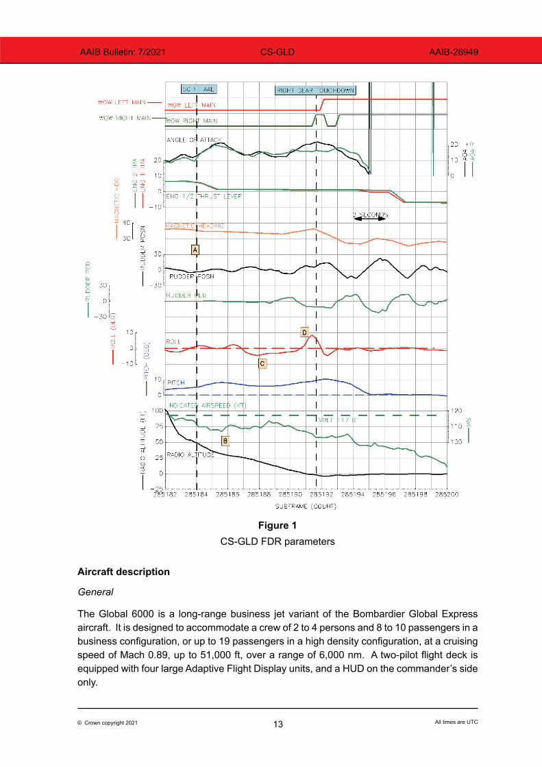
At 1145:01 hrs, the aircraft reached 50 ft radio altitude (RA) (Figure 1, point A) with an indicated airspeed of 114 kt and a magnetic heading of 035.4°. The onboard derived wind was a 16.8 kt crosswind from the right.
Two seconds later the aircraft passed through a RA of 30 ft (point B) at an airspeed of 109 kt. The control column was moved progressively aft, with a corresponding increase in aircraft attitude to 9.1° nose up. The aircraft started rolling left (point C) reaching a maximum bank angle of 4.4° left wing down at a RA of 20 ft. As the aircraft started rolling left, the control wheel was moved to a 34.7° right roll command, reducing to 24.2° 1.3 seconds later, along with right rudder pedal producing a rudder deflection of 7.4° to the right. Within this time frame, the aircraft started rolling back to wings level, and the right multifunction spoiler had started to deploy, reaching 5° deflection, where it remained for 1.5 seconds before returning to the retracted position. A data plot of the relevant parameters is shown at Figure 1.
Half a second before touchdown (point D), the roll rate increased to a peak of 14.3°/s right wing down, to which a control wheel input was made to 62.1° left wing down. The right main landing gear touched down first with the aircraft at its peak roll attitude of 8.5° to the right and a pitch attitude of 9.1° nose-up. The aircraft then rolled to the left as the pitch continued to increase to a peak of 10.5° nose-up a second later.
Manufacturer’s analysis
Data was sent to the aircraft manufacturer who provided an interpretation of the landing phase. Of significance was the assessment of the yaw damper operation, which was:
‘Until the aircraft reached a height of 30 ft radio altimeter, rudder deflection ranged between 5.2° trailing edge right to 4.9° trailing edge left. The yaw damper was engaged, and the range of rudder deflection was consistent with yaw damper nominal authority of +/- 6.5° with no rudder pedal movement’.
13© Crown copyright 2021 All times are UTC
AAIB Bulletin: 7/2021 CS-GLD AAIB-26949
Figure 1
CS-GLD FDR parameters
Aircraft description
General
The Global 6000 is a long-range business jet variant of the Bombardier Global Express aircraft. It is designed to accommodate a crew of 2 to 4 persons and 8 to 10 passengers in a business configuration, or up to 19 passengers in a high density configuration, at a cruising speed of Mach 0.89, up to 51,000 ft, over a range of 6,000 nm. A two-pilot flight deck is equipped with four large Adaptive Flight Display units, and a HUD on the commander’s side only.
14© Crown copyright 2021 All times are UTC
AAIB Bulletin: 7/2021 CS-GLD AAIB-26949
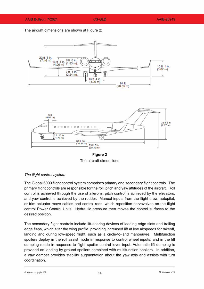
The aircraft dimensions are shown at Figure 2:
Figure 2
The aircraft dimensions
The flight control system
The Global 6000 flight control system comprises primary and secondary flight controls. The primary flight controls are responsible for the roll, pitch and yaw attitudes of the aircraft. Roll control is achieved through the use of ailerons, pitch control is achieved by the elevators, and yaw control is achieved by the rudder. Manual inputs from the flight crew, autopilot, or trim actuator move cables and control rods, which reposition servovalves on the flight control Power Control Units. Hydraulic pressure then moves the control surfaces to the desired position.
The secondary flight controls include lift-altering devices of leading edge slats and trailing edge flaps, which alter the wing profile, providing increased lift at low airspeeds for takeoff, landing and during low-speed flight, such as a circle-to-land manoeuvre. Multifunction spoilers deploy in the roll assist mode in response to control wheel inputs, and in the lift dumping mode in response to flight spoiler control lever input. Automatic lift dumping is provided on landing by ground spoilers combined with multifunction spoilers. In addition, a yaw damper provides stability augmentation about the yaw axis and assists with turn coordination.
15© Crown copyright 2021 All times are UTC
AAIB Bulletin: 7/2021 CS-GLD AAIB-26949
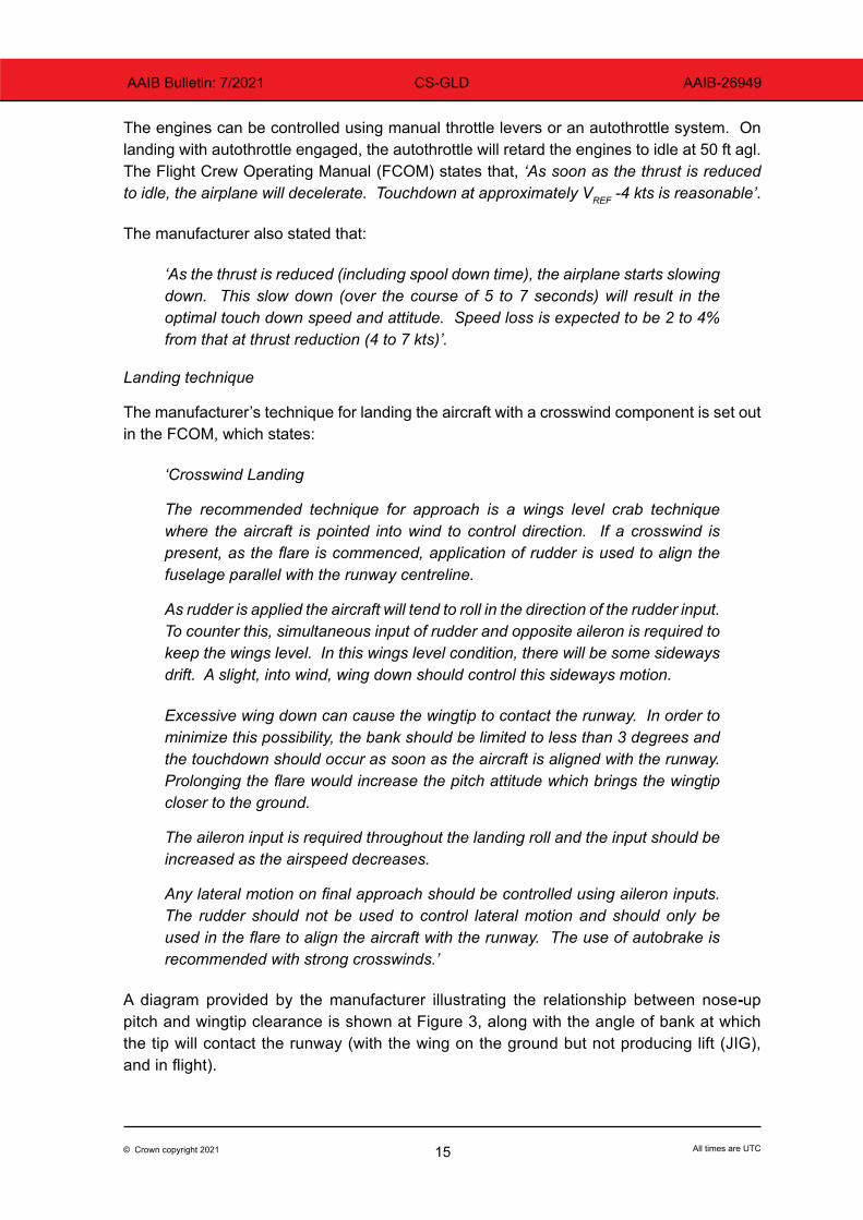
The engines can be controlled using manual throttle levers or an autothrottle system. On landing with autothrottle engaged, the autothrottle will retard the engines to idle at 50 ft agl. The Flight Crew Operating Manual (FCOM) states that, ‘As soon as the thrust is reduced to idle, the airplane will decelerate. Touchdown at approximately VREF -4 kts is reasonable’.
The manufacturer also stated that:
‘As the thrust is reduced (including spool down time), the airplane starts slowing down. This slow down (over the course of 5 to 7 seconds) will result in the optimal touch down speed and attitude. Speed loss is expected to be 2 to 4% from that at thrust reduction (4 to 7 kts)’.
Landing technique
The manufacturer’s technique for landing the aircraft with a crosswind component is set out in the FCOM, which states:
‘Crosswind Landing
The recommended technique for approach is a wings level crab technique where the aircraft is pointed into wind to control direction. If a crosswind is present, as the flare is commenced, application of rudder is used to align the fuselage parallel with the runway centreline.
As rudder is applied the aircraft will tend to roll in the direction of the rudder input. To counter this, simultaneous input of rudder and opposite aileron is required to keep the wings level. In this wings level condition, there will be some sideways drift. A slight, into wind, wing down should control this sideways motion.
Excessive wing down can cause the wingtip to contact the runway. In order to minimize this possibility, the bank should be limited to less than 3 degrees and the touchdown should occur as soon as the aircraft is aligned with the runway. Prolonging the flare would increase the pitch attitude which brings the wingtip closer to the ground.
The aileron input is required throughout the landing roll and the input should be increased as the airspeed decreases.
Any lateral motion on final approach should be controlled using aileron inputs. The rudder should not be used to control lateral motion and should only be used in the flare to align the aircraft with the runway. The use of autobrake is recommended with strong crosswinds.’
A diagram provided by the manufacturer illustrating the relationship between nose-up pitch and wingtip clearance is shown at Figure 3, along with the angle of bank at which the tip will contact the runway (with the wing on the ground but not producing lift (JIG), and in flight).

16© Crown copyright 2021 All times are UTC
AAIB Bulletin: 7/2021 CS-GLD AAIB-26949
PITCH˚ JIG˚ FLIGHT˚0 10.6 13.53 9.6 12.36 8.5 11.29 7.4 10.1
Figure 3Nose-up pitch attitude and angle of bank at wingtip contact
Approach airspeed gust correction
When ATC reports gusts in windspeed, an increment is added to VREF as set out in the Operator’s Operations Manual Part B, shown below. The conditions during this approach were light turbulence but with no gusts reported. Adding gust increments also requires the increased Landing Distance Required to be considered.
‘2.12.3 GUST CORRECTION
Approach speed on finals is calculated as VREF + ½ the gust value up to maximum correction of 10 knots. Example: The gust value of a wind 27020G35 is 15 knots. The correction for VREF is ½ x 15 = 8 knots. If a gust correction is calculated, set the speed on the FCP3. With autothrottle engaged, this corrected speed will be held until 50 ft AGL, when the autothrottle retards. Therefore, it is important that the resulting increase in landing distance has been considered with reference to the following factors:
Footnote3 FCP: Flight Control Panel.
17© Crown copyright 2021 All times are UTC
AAIB Bulletin: 7/2021 CS-GLD AAIB-26949
A 1 knot increase above VREF increases the landing distance by 2%, thus:
VREF + 5 increases the landing distance required by 10%:
VREF + 10 increases landing distance required by 20%’.
‘Note: It is recommended to disengage the autothrottle during gusty approaches.’
Landing attitude and roll control
The manufacturer also provided an indication of the nose-up attitude on the final approach at VREF on a 3° glideslope, based on flight test data. The PAPIs at Biggin Hill, Runway 03 are set to 4° approach angle.
‘The Global 6000 attitude on approach at VREF is approximately 4° while on a 3° approach. At VREF + 5 (for ½ gust), attitude is about 3° while on a 3° approach. Bombardier selected an optimal height above ground (50 ft) for thrust reduction to optimize landing distance and handling. This was meant to expose the airplane to an air-time of about 5 to 7 seconds in calm air’.
The effectiveness of the ailerons at low airspeed was demonstrated during a VMCL4 Flight
Test point as follows:
‘The static VMCL demonstration for the slats out, flap 30°, landing gear down configuration was completed with the right engine at 99.6% of maximum takeoff power and the left engine shutdown. A constant heading was maintained to stick shaker activation at 89 KIAS using 19° of rudder and 3.9° of bank into the operating engine. The roll through 20° was completed in 3.1 seconds without using full roll control’.
Head Up Display
The HUD generates and superimposes flight data into the pilot’s field of view. Displayed symbology is derived from aircraft flight instruments and navigation sensor data. The HUD is available during all phases of flight and serves to enhance situational awareness, aid in more precise aircraft handling and improve energy management.
A dual-channel computer receives data similar to that displayed on the pilot flight displays. Displayed information includes flight monitoring data (altitude, airspeed, inertial flightpath and acceleration), flight director information (autothrottle modes and related guidance cues), and situation and navigation data (position, altitude, course, heading, track, wind groundspeed and other navigation data). As the aircraft descends through 50 ft RA, a flare cue (+) is shown above each wing of the FPV referenced to the horizon line. Both the flightpath reference line and the flare cue remain displayed during the approach and are removed at main gear touchdown. They are flare cues and do not provide guidance.
Footnote4 VMCL: the minimum speed the aircraft can be controlled in the air in the landing configuration, while applying
maximum possible variations of power on the remaining engine after failure of the critical engine.
18© Crown copyright 2021 All times are UTC
AAIB Bulletin: 7/2021 CS-GLD AAIB-26949
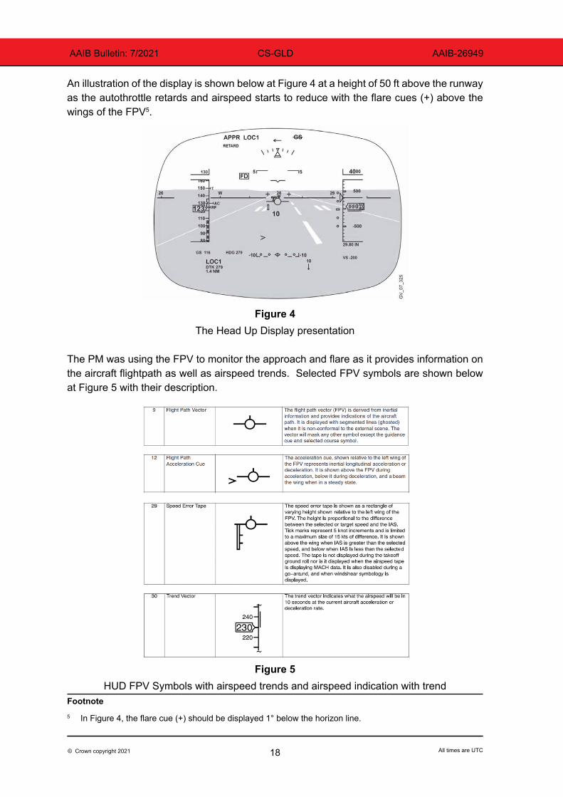
An illustration of the display is shown below at Figure 4 at a height of 50 ft above the runway as the autothrottle retards and airspeed starts to reduce with the flare cues (+) above the wings of the FPV5.
Figure 4The Head Up Display presentation
The PM was using the FPV to monitor the approach and flare as it provides information on the aircraft flightpath as well as airspeed trends. Selected FPV symbols are shown below at Figure 5 with their description.
Figure 5
HUD FPV Symbols with airspeed trends and airspeed indication with trendFootnote5 In Figure 4, the flare cue (+) should be displayed 1° below the horizon line.

19© Crown copyright 2021 All times are UTC
AAIB Bulletin: 7/2021 CS-GLD AAIB-26949
Aircraft damage
When the right wingtip contacted the runway, four areas of the structure were damaged as they briefly scraped along the runway. They were the underside of the winglet, the aileron, wing leading edge and both outer canoe fairings. The damage is shown below at Figure 6.
Figure 6The damaged components which contacted the runway
Airfield information
Biggin Hill Airport has a single runway orientated 03/21, which is 1,820 m long and 45 m wide with a 1.13° downslope on Runway 03. The Landing Distance Available for Runway 03 is 1,555 m. The airfield elevation is 599 ft, with a deep valley immediately before a road on the edge of the airfield adjacent to the threshold of Runway 03. The valley slopes up steeply towards the Runway 03 threshold. The PAPIs for Runway 03 are set to a 4° approach angle. The airport surface wind speed and direction is reported by the Air Traffic Control Officer (ATCO) using equipment in the tower connected to two sensors located near the thresholds of Runways 03 and 21. The ATCOs select which sensor to use according to the wind direction. The equipment constantly displays wind speed, direction and variation, and has three settings: instant wind direction and speed; a two-minute average, which is used for the ATIS; and 10-minute average used for the METAR. The normal operating position is the two-minute setting, but “instant wind” can be selected at ATCO discretion (normally if the gusts are much greater than 10 kt) or when requested by the pilot.

20© Crown copyright 2021 All times are UTC
AAIB Bulletin: 7/2021 CS-GLD AAIB-26949
The airfield chart is shown at Figure 7.
Figure 7 The Biggin Hill Airport chart
Tests and research
Background
The operator and the manufacturer had previously held discussions regarding wingtip strikes against a background of earlier events and near contacts. A concern of the operator had been the possibility of the down-going wing stalling at a speed below VREF in ground effect and dropping to contact the runway. Both pilots on the incident flight
21© Crown copyright 2021 All times are UTC
AAIB Bulletin: 7/2021 CS-GLD AAIB-26949
thought that adding an increment to VREF during turbulence or crosswinds, even without gusts reported, might reduce the risk of wingtip strikes. This proposal had previously been put to the manufacturer but was not supported by them for smooth constant crosswinds or as a general procedure. Adding more speed on top of the appropriate gust addition could present additional challenges during the landing phase.
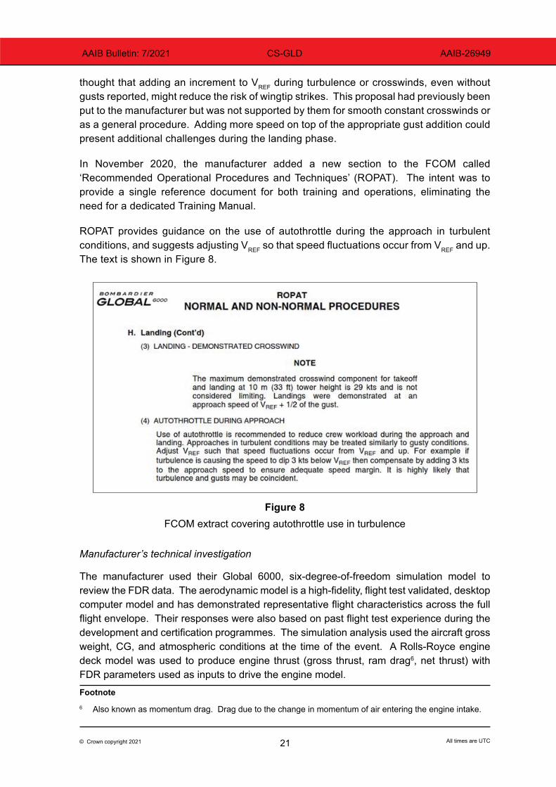
In November 2020, the manufacturer added a new section to the FCOM called ‘Recommended Operational Procedures and Techniques’ (ROPAT). The intent was to provide a single reference document for both training and operations, eliminating the need for a dedicated Training Manual.
ROPAT provides guidance on the use of autothrottle during the approach in turbulent conditions, and suggests adjusting VREF so that speed fluctuations occur from VREF and up. The text is shown in Figure 8.
Figure 8FCOM extract covering autothrottle use in turbulence
Manufacturer’s technical investigation
The manufacturer used their Global 6000, six-degree-of-freedom simulation model to review the FDR data. The aerodynamic model is a high-fidelity, flight test validated, desktop computer model and has demonstrated representative flight characteristics across the full flight envelope. Their responses were also based on past flight test experience during the development and certification programmes. The simulation analysis used the aircraft gross weight, CG, and atmospheric conditions at the time of the event. A Rolls-Royce engine deck model was used to produce engine thrust (gross thrust, ram drag6, net thrust) with FDR parameters used as inputs to drive the engine model.Footnote6 Also known as momentum drag. Drag due to the change in momentum of air entering the engine intake.

22© Crown copyright 2021 All times are UTC
AAIB Bulletin: 7/2021 CS-GLD AAIB-26949
Simulation modelling
To establish if the angle of attack (AOA) of the wing just before the wingtip strike was within the normal AOA range, various landings carried out during the development and certification flight test programme were reviewed. Pitch angles at touchdown were generally between 6.5° and 8.0°. However, the touchdown pitch angles in service are expected to be closer to the lower range at around 6.5°. Although CS-GLD FDR data labels the AOA as body angles (AOA-b), they are actually Stall Protection System vane angles (AOA-v). The AOA-v reads generally higher than AOA-b and can be converted to AOA-b through a calibration curve.
‘Abuse’ landing cases carried out during certification (landings performed at VREF - 5 kt) showed pitch angles up to 9°, similar to the event, but with AOA-b slightly lower than in the event. The AOA value in the event was above the range expected for a landing carried out at an appropriate VREF with a typical assumed loss of airspeed from the flare to touchdown (about 4% of VREF).
With respect to the rolling motion to the right observed just prior to touchdown, the simulation model did not reproduce that behaviour from the flight control inputs alone. However, the FDR data parameters and low sampling frequency did not allow for further root cause identification. Flight reconstruction was limited and key external influences, such as localized winds and gusts, could not be properly accounted for. The analysis did not see any evidence of a stall on the wing, which might have been indicated by a decrease in vertical acceleration (Nz).
Roll rate recorded on the FDR indicated a peak of 14.3˚/sec (to the right); however, the manufacturer explained that this was a snapshot of the rate at that instant of the FDR sample. The FDR sampling rate for that parameter was only once per second. The simulation analysis, output at a much higher sampling rate, showed that the flight control inputs that were applied to counter the right roll rate were acting to arrest the wing-drop and would have eventually recovered it if sufficient height had been available; in the event, reaction forces from the landing gear and the wing tip contacting the runway contributed to arresting the wing-drop. However, the observation from the simulation analysis supported a conclusion that the wing had not stalled.
The aerodynamic simulation model was used to determine the change in AOA in ground effect. There was good correlation between the model output and the FDR data, up to just before the wing made contact with the runway. Based on all the aircraft data available for this wing, the lift coefficient remains linear in this AOA range and ‘a good margin to the stall is maintained’.
Even with the reduction in airspeed below VREF observed in the event, flow separation on the wings would not be expected. However, the lower airspeed would reduce the roll response. The roll response of the aircraft, for a given aileron/multifunction spoiler deflection, is a function of the dynamic pressure (or the square of the airspeed). At a VREF of 117 KCAS, the dynamic pressure is 46.3 pounds per square foot (psf), while at the expected touchdown speed of 112 KCAS, dynamic pressure would be 42.5 psf. The touchdown speed of CS-GLD based on the FDR data was measured at 106 KCAS, which corresponds to a dynamic
23© Crown copyright 2021 All times are UTC
AAIB Bulletin: 7/2021 CS-GLD AAIB-26949
pressure of 38 psf. It is therefore reasonable to expect that there was a reduction of roll response of approximately 20% between when the aircraft was approaching at VREF and at touchdown.
Throughout the development and certification flight test programme of the Global aircraft, many landings were carried out at an approach speed of VREF - 5 knots, flap 30, slats out and at various weights. In particular, a few tests were performed with a touchdown speed around 103 KCAS, but with stable, into wind conditions. In spite of the lower dynamic pressure at that speed, ‘no handling issues were reported by the flight test crew’.
The manufacturer was asked to establish if the autothrottle had maintained the VREF target speeds within the design specification. The autothrottle is designed to maintain the selected airspeed within +/- 4 kt in calm air conditions. The selected reference speed (VREF) was 126 kt between 1,000 ft and 435 ft RA, and the selection was then changed to 117 kt for the rest of the final approach. At 50 ft RA the autothrottle commanded the throttle to idle, and it disconnected on main gear touchdown. The lowest airspeed reached while the autothrottle speed tracking was active was 114 kt. The review concluded that, ‘The [autothrottle system] performed as expected’.
The review and analysis of the FDR data and simulation model output concluded that the AOA value in the event was above the range expected for a landing carried out at an appropriate VREF with a typical assumed loss of airspeed from the flare to touchdown. However, flight reconstruction was limited and key external influences such as localised winds and gusts could not be properly accounted for. The analysis did not see any evidence of a stall, which might have been indicated by a decrease in vertical acceleration (Nz). While there was a significant margin of airspeed above the stall, the review was unable to conclusively state that there was not a reduction of lift on the right wing during the roll to the right. However, modelling showed that without unidentified external influences and with sufficient height available, the opposite control inputs would have rolled the aircraft to the left, reducing the angle of bank to the right, and perhaps avoiding the impact.
Analysis
The crew were properly rested and licensed to conduct the flight, which was their fifth sector in two days. During their pre-flight briefing, they had discussed the weather at Biggin Hill and had planned to carry out a circle-to-land approach. The transit from Edinburgh was uneventful and the FDR data showed nothing abnormal, with some light turbulence on the final approach causing the airspeed to fluctuate +/- 2 kt. Prior to that, there had been no rudder pedal movements from the PF, with the yaw damper driving rudder movement to coordinate roll inputs (the manufacturer assessed that the yaw damper was operating correctly and did not contribute to the event).
At 30 ft above the runway, the aircraft flare was progressively increased to a +9.1° nose-up attitude. During that attitude change, the aircraft initially rolled left to a 4.4° bank angle before the pilot reversed the roll and applied right rudder and control wheel, which caused the aircraft to roll to the right. This roll rate peaked at 14.3°/s, resulting in an angle of

24© Crown copyright 2021 All times are UTC
AAIB Bulletin: 7/2021 CS-GLD AAIB-26949
bank of 8.5° to the right at a pitch angle of 9.1˚, and at a height of 1.5 ft with an airspeed of 105 kt. To restore wings level for touchdown, the pilot made a large left roll input, but before it could take effect the right main landing gear compressed at touchdown. The right wingtip contacted the runway surface before the aircraft rolled left and the left gear touched down. Just before touchdown, the aircraft system computed the wind was from 099° at 19 kt giving a crosswind component of 18.1 kt with an aircraft heading of 036°.
The aircraft was yawed to the right during the final stages of the approach but, apart from a small left rudder input, it did not appear to have been yawed left to align with the runway. During the flare, a roll angle of 8.5° developed to the right, which was greater than the 3° limit given by the manufacturer for landing in a crosswind. With a nose-up pitch attitude of 9°, the roll angle required for a wingtip to contact the runway is 7.4° with the wing unloaded and 10.1° in flight.
Roll control effectiveness was reduced by approximately 20% as the airspeed decayed from the VREF of 117 kt to the touchdown speed of 106 kt. However, during certification flight testing, roll control was demonstrated down to 89 kt in the landing configuration.
The manufacturer’s modelling showed that the aircraft’s rate of roll to the right just before the wingtip contacted the runway was not solely the result of the pilot’s flight control inputs. They considered that: ‘Important external or other influences that could have provoked the right roll to wing tip contact at touchdown, could not be identified with the data and tools available’. There were no gusts reported by ATC, but it was likely that localised wind or gusts caused the additional right roll identified by the simulation.
Conclusion
The serious incident occurred when large right rudder and roll inputs just before touchdown combined with unidentified external or other influences - likely to be localised wind or gust effects - to cause a rapid roll to the right and a bank angle which exceeded the recommended maximum of 3°. Despite a prompt and positive reversal of those inputs, the nose-up pitch attitude combined with the rate of roll reduced the wing tip clearance to the extent that the right wingtip contacted the runway surface.