boiler management units lmu34 - nicon servniconserv.ro/files/023_n7491en.pdf · integrated hmi with...
TRANSCRIPT

CC1N7491en 07.04.2015
Building Technologies Division
7491
Boiler Management Units LMU34...
LMU34... are used for premix condensing gas-fired boilers with pneumatic air / gas ratio control and modulating fan. The LMU34... and this Data Sheet are intended for use by OEMs which integrate the BMUs in their products.
Use
The LMU34… provide all functions required for gas-fired heating boilers in intermittent operation, burner capacity up to 70 kW. Gas modulation takes place by fan speed variation. The LMU34... are designed for residential applications only. Functions for central heating (CH), with or without weather compensation Functions for domestic hot water (DHW), with instantaneous heater, etc.
(depending on the type of LMU34...) Function condensate pump (depending on the type of LMU34...) Integrated HMI with simple parameter settings / readout of installation data Interchangeable L / N mains supply (depending on the type of LMU34...) Options (depending on the type of LMU34...)
1. Auxiliary module AGU2.002... for digital room unit QAA73... (LMU34... parameter settings via QAA73...) and additional output for central heating pump 2. PC software tool for trending / parameter settings (for laboratory and production) 3. YPLAN applications (for UK)
Note! For more details, refer to LMU34... specification!
Key features
2/29
Building Technologies Division CC1N7491en 07.04.2015
Warning notes
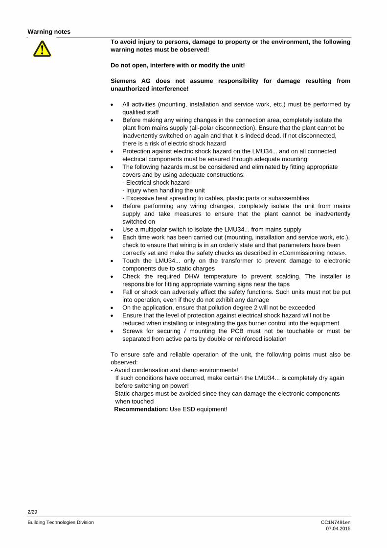
To avoid injury to persons, damage to property or the environment, the following warning notes must be observed! Do not open, interfere with or modify the unit! Siemens AG does not assume responsibility for damage resulting from unauthorized interference! All activities (mounting, installation and service work, etc.) must be performed by
qualified staff Before making any wiring changes in the connection area, completely isolate the
plant from mains supply (all-polar disconnection). Ensure that the plant cannot be inadvertently switched on again and that it is indeed dead. If not disconnected, there is a risk of electric shock hazard
Protection against electric shock hazard on the LMU34... and on all connected electrical components must be ensured through adequate mounting
The following hazards must be considered and eliminated by fitting appropriate covers and by using adequate constructions: - Electrical shock hazard - Injury when handling the unit - Excessive heat spreading to cables, plastic parts or subassemblies
Before performing any wiring changes, completely isolate the unit from mains supply and take measures to ensure that the plant cannot be inadvertently switched on
Use a multipolar switch to isolate the LMU34... from mains supply Each time work has been carried out (mounting, installation and service work, etc.),
check to ensure that wiring is in an orderly state and that parameters have been correctly set and make the safety checks as described in «Commissioning notes».
Touch the LMU34... only on the transformer to prevent damage to electronic components due to static charges
Check the required DHW temperature to prevent scalding. The installer is responsible for fitting appropriate warning signs near the taps
Fall or shock can adversely affect the safety functions. Such units must not be put into operation, even if they do not exhibit any damage
On the application, ensure that pollution degree 2 will not be exceeded Ensure that the level of protection against electrical shock hazard will not be
reduced when installing or integrating the gas burner control into the equipment Screws for securing / mounting the PCB must not be touchable or must be
separated from active parts by double or reinforced isolation To ensure safe and reliable operation of the unit, the following points must also be observed: - Avoid condensation and damp environments!
If such conditions have occurred, make certain the LMU34... is completely dry again before switching on power!
- Static charges must be avoided since they can damage the electronic components when touched
Recommendation: Use ESD equipment!

3/29
Building Technologies Division CC1N7491en 07.04.2015
Engineering notes
The boiler manufacturer is responsible for correct parameterization of the LMU34... The parameter settings must be in compliance with the relevant standards and directives (e.g. boiler standards)!
Application notes
Notes on integrating the LMU34… (heating boiler for gaseous fuels type C, rated capacity 70 kW): The impact of continuous control of the ignition equipment caused by an internal
failure of one of the burner control components in connection with an earth fault of one of the connecting wires of the ignition equipment must be assessed depending on the application
High limit thermostat function Signals from the potential-free contact at terminals X401: X401 pin 3 / X401 pin 4 will be further handled by the LMU34… in a safety-related manner. Functions ”Shutdown”, “Lockout” and “Reset” are implemented in the LMU34… and are in compliance with EN 298 and DIN V ENV 14459 (class C)
Signals from the flue gas limiter (thermo fuse) fed to terminals X401: X401 pin 1 / X401 pin 2 will be further handled in a non-safety-related manner (class A)
Identification code to EN 298 A M C L X N The LMU34... conforms to standard for gas boiler type C so DIN EN 483: 2000 (gas boiler for central heating). The LMU34.3… conforms to CSA / ANSI Z21.20b 2001 < 117 kW.
Note! Prepurge, postpurge and interpurge times including all fan-related parameters (speed, PWM) are non-safety-related. The boiler must meet the requirements of 6.4.5 (according to EN 483:2000) through other means (e.g. by a gas valve which must meet special requirements)
Mounting notes
The electrical wiring inside the boiler must conform to country-specific and local regulations. The rated loads and the rating of the unit fuse must be taken into account
Ensure that the relevant national safety regulations are complied with Make certain that spliced individual wires cannot get into contact with neighboring
terminals Electromagnetic emissions must be checked on an application-specific basis The unit must be mounted within a closed housing When mounted inside the boiler, the maximum permissible ambient temperature
must not be exceeded On the boiler, fit the unit in a housing (degree of protection min. IP40 or IP54 for
outdoor use) Resistor R114 can reach high temperatures in operation. This must be considered
when mounting and servicing the PCB

4/29
Building Technologies Division CC1N7491en 07.04.2015
Installation notes
The LMU34... cannot be operated on isolated networks (with no reference to ground)
The high limit thermostat (TB) must be short-circuit proof and adequately secured in its position
Do not mix up live and neutral conductors (only LMU34.300...) Install switches, fuses and earthing, in compliance with local regulations Make certain that the maximum permissible current rating of the connection
terminals is not exceeded When wiring the unit, ensure that mains voltage and protective extra low-voltage
are always strictly separated to warrant protection against electrical shock hazard (according to DIN EN 60730-2-5)!
Only use high-quality and heat-resistant earthing cable On the application, it must be ensured that the connections for functional earth
(burner ground) are connected to protective earth with low impedance The process-related inputs (X300, X400, and X401) are segregated from mains
supply by double or reinforced isolation and powered by protective extra low-voltage (PELV) via a safety isolating transformer. For the PWM fan output (X401: Pin 7 / 8) and the Hall sensor input (X401: Pin 5 / 6), double or reinforced isolation against active live parts must be ensured on the application itself
Ensure that the level of protection against electrical shock hazard will not be reduced when installing or integrating the unit into the equipment
When making the boiler isolation test, functional earth (X500 / X900) must be connected. If not, isolation on the LMU34... will not be tested
Use of high-efficiency pumps
When using high-efficiency pumps or pumps with integrated electronics, the resulting switch-on currents can adversely affect the relays’ service life. For this reason, use of these types of pump is permitted only if previously authorized in writing by Siemens AG.
5/29
Building Technologies Division CC1N7491en 07.04.2015
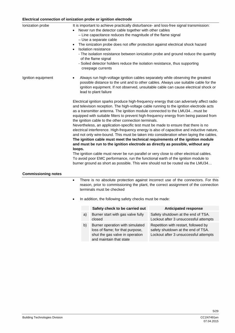
Electrical connection of ionization probe or ignition electrode
It is important to achieve practically disturbance- and loss-free signal transmission: Never run the detector cable together with other cables
– Line capacitance reduces the magnitude of the flame signal – Use a separate cable
The ionization probe does not offer protection against electrical shock hazard Isolation resistance
- The isolation resistance between ionization probe and ground reduce the quantity of the flame signal - Soiled detector holders reduce the isolation resistance, thus supporting creepage currents
Always run high-voltage ignition cables separately while observing the greatest
possible distance to the unit and to other cables. Always use suitable cable for the ignition equipment. If not observed, unsuitable cable can cause electrical shock or lead to plant failure
Electrical ignition sparks produce high-frequency energy that can adversely affect radio and television reception. The high-voltage cable running to the ignition electrode acts as a transmitter antenna. The ignition module connected to the LMU34…must be equipped with suitable filters to prevent high-frequency energy from being passed from the ignition cable to the other connection terminals. Nevertheless, an application-specific test must be made to ensure that there is no electrical interference. High-frequency energy is also of capacitive and inductive nature, and not only wire-bound. This must be taken into consideration when laying the cables. The ignition cable must meet the technical requirements of the ignition module and must be run to the ignition electrode as directly as possible, without any loops. The ignition cable must never be run parallel or very close to other electrical cables. To avoid poor EMC performance, run the functional earth of the ignition module to burner ground as short as possible. This wire should not be routed via the LMU34…
Commissioning notes
There is no absolute protection against incorrect use of the connectors. For this reason, prior to commissioning the plant, the correct assignment of the connection terminals must be checked
In addition, the following safety checks must be made:
Safety check to be carried out Anticipated response
a) Burner start with gas valve fully closed
Safety shutdown at the end of TSA. Lockout after 3 unsuccessful attempts
b) Burner operation with simulated loss of flame; for that purpose, shut the gas valve in operation and maintain that state
Repetition with restart, followed by safety shutdown at the end of TSA. Lockout after 3 unsuccessful attempts
Ionization probe
Ignition equipment

6/29
Building Technologies Division CC1N7491en 07.04.2015
Standards and certificates
Conformity to EEC directives - Electromagnetic compatibility EMC (immunity) - Low-voltage directive - Directive for gas-fired appliances
2004/108/EC 2006/95/EC 2009/142/EC
ISO 9001:2008 ISO 14001:2004 OHSAS 18001:2007
Service notes
Each time a unit has been replaced, check all safety functions. In the event of blown fuses external to the LMU34…, the unit must be
returned to Siemens AG (apply to safety checks)
Life cycle
LMU34... boiler management unit have a designed lifetime* of 250,000 burner startup cycles which, under normal operating conditions in heating mode, correspond to approx. 10 years of usage (starting from the production date given on the type field). This lifetime is based on the endurance tests in the standard EN 298. A summary of the conditions has been published by the European Control Manufacturers Association (Afecor) (www.afecor.org). The designed lifetime is based on use of the BMUs according to the manufacturer’s Data Sheet. After reaching the designed lifetime in terms of the number of burner startup cycles, or the respective time of usage, the BMU is to be replaced by authorized personnel. * The designed lifetime is not the warranty time specified in the Terms of Delivery
Disposal notes
The unit contains electrical and electronic components and must not be disposed of together with domestic waste. Local and currently valid legislation must be observed.
Type summary
Type
Mai
ns v
olta
ge
Pha
se (
L) /
neut
ral c
ondu
ctor
(N
) in
terc
hang
eab
le
Inte
rfac
e to
A
GU
2.00
2...
(O
penT
herm
/
pum
p m
odul
e)
Inte
grat
ed
DH
W r
elay
DH
W r
elay
as
a co
nden
sate
pum
p
CS
A a
ppro
val
Remark
LMU34.210... AC 230 V
LMU34.215... AC 230 V
LMU34.216... AC 230 V
LMU34.220... AC 230 V With software 02.12
LMU34.3... AC 120 V

7/29
Building Technologies Division CC1N7491en 07.04.2015
Accessories (to be ordered separately)
Room unit (depending on the type of LMU34...) QAA73...- Refer to Basic Documentation P2284
Interface and pump module (depending on the type of LMU34...) AGU2.002A…- For QAA73
Relay PCB AGU2.005A... For control a high-efficiency pump via LMU34... On request See Data Sheet N7217
Communication interface - Interface for parameterization software ACS425 OCI425 - Interface for laboratory tool ACS420 OCI490...
PC software - Software tool for laboratory ACS420 - Software tool for parameterization ACS425
Outside sensor QAC34- Refer to Data Sheet Q1811
Screwed immersion temperature sensor QAK36…- NTC 10 k - Refer to Data Sheet Q1844
Cable temperature sensor QAZ36.522/109- NTC 10 k - Cable length 2 m - Refer to Data Sheet Q1843
Cable temperature sensor QAZ36.526/109- NTC 10 k - Cable length 6 m - Refer to Data Sheet Q1843
Ionization probe supplied by thirds

8/29
Building Technologies Division CC1N7491en 07.04.2015
Technical data
Mains voltage - LMU34.2… - LMU34.3…
AC 230 V +10 % / -15 % AC 120 V +10 % / -15 %
Mains frequency - LMU34.2… - LMU34.3…
50 Hz ±5 % 60 Hz ±5 %
Power consumption (with no loads) 10 VA Degree of protection IP00
IP40 or IP54 (to be ensured through mounting)
Safety class 0 Mounting position Vertical (refer to illustration)
7491z06/1204
Dimensions (L x W x D) 160 x 127 x 43.05 mm Weight Approx. 300 g Unit fuses to IEC127 (mains supply) - External side LMU34.2... LMU34.3...
T2 H 250 Terminals «L» and «N» (X1) Terminal «L» (X1)
Material PCB FR4, dual copper layers
Transformer 5 VA thermo fuse 131 °C safety transformer to EN 61558-2-6
Storage DIN EN 60721-3-1 Climatic conditions Class 1K3 Mechanical conditions Class 1M2 Temperature range -20...+60 °C Humidity <90 % r.h. Transport DIN EN 60721-3-2 Climatic conditions Class 2K2 Mechanical conditions Class 2M2 Temperature range -20...+70 °C Humidity <90 % r.h. Operation DIN EN 60721-3-3 Climatic conditions Class 3K3 Mechanical conditions Class 3M2 Temperature range 0...+70 °C Humidity <90 % r.h.
Caution! Condensation, formation of ice and ingress of water are not permitted!
LMU34… General unit data
Environmental conditions

9/29
Building Technologies Division CC1N7491en 07.04.2015
Technical data (cont´d)
Connector X1 Type Siemens AG system-internal connection
cable is supplied together with AGU2.002…, 5 poles, coded
Loads Connected to LMU34… (PELV) Siemens AG system-internal connection
Function Interface for LMU34… Connector X2 Type Stocko: MKS1852-6-0-202
2 poles, coded AGU2.002… connections 7 and 8 interchangeable and short-circuit-proof short-circuit might lead to activation of special LMU34… functions Lumberg: 2.5 MSF02(3114) 2 poles
Loads Connected to LMU34… PELV Siemens AG system-internal connection
Function Interface (OpenTherm) for QAA73… for more detailed information, refer to OpenTherm specification and Basic Documentation QAA73… (P2284)
Connector X3 Type Molex: 1008-5031
3 poles, coded Loads AC 230 V
2 A, cos 0.8 Imax fusing max. T3.15H250 to IEC127
Assignment Function AGU2.002… pin 11: relay NC contact pin 10: relay NO contact pin 9: relay COM contact
Function Changeover contact for control of zone pump / of zone valve NO contact closed when there is a heat request from QAA73… NC contact closed when there is no heat request from QAA73…
Caution! The AGU2.002… has switching circuits operating on protective extra low-voltage and switching circuits operating on mains voltage. On the application, ensure that the required isolation will be observed (cabling, etc.).
Ionization current DC switching threshold 0.45 µA (typically) Response time in the event of loss of flame <1 s Safety time «TSA» 5 s (depending on type of device) Repetition Max. 3
AGU2.002… General unit data
Flame supervision with ionization probe

10/29
Building Technologies Division CC1N7491en 07.04.2015
External system components
External system components are devices such as Ignition equipment Fan Gas valve Flow switch Hall sensor DHW
The external system components used must be approved by Siemens AG!

11/29
Building Technologies Division CC1N7491en 07.04.2015
Functions
Modulating control in both central heating (CH) and domestic hot water (DHW) mode
PID control of the heating water temperature PID control of the DHW temperature (DHW outlet temperature) (depending on the
type of LMU34...) NTC temperature sensor on central heating flow pipe NTC temperature sensor on instantaneous DHW line or storage tank (depending
on the type of LMU34...) Connection facility for a CH programmer / timer Connection facility for a non-safety-related flow switch (CH) or water pressure
switch Frost protection CH system (boiler only) Frost protection DHW (boiler only) (depending on the type of LMU34...) Flame supervision by ionization Nonvolatile lockout in the event of loss of flame Nonvolatile lockout in case of high limit thermostat (TB) response Flue gas NTC temperature sensor input or flue gas thermostat input with non-
safety-related function Programmable fault response on flue gas failure: Volatile burner stop or nonvolatile
lockout Multitry ignition sequence Outside sensor input Integrated weather compensation of CH Pumps kick function and valves kick function 3 LEDs for status signals 2 x 7 segment red displays of temperature, faults and diagnostic data Auxiliary module AGU2.002… (depending on the type of LMU34...) CH potentiometer and DHW potentiometer with additional service functions Control of fan speed (non-safety-related) Connection to PC tool interface OCI490... / OCI425 with corresponding software
ACS… (laboratory use) OpenTherm (parameter settings for LMU34... via QAA73) (depending on the type
of LMU34...) Control condensate pump (depending on the type of LMU34...) Function modes: The general function modes are: Standby Frost protection Combi comfort Central heating DHW (combi or storage tank) (depending on the type of LMU34...) Chimney sweep function Controller stop function Anomaly Operating modes (OFF, summer, winter, remote and reset): The following operating modes can be selected by means of the external rotary switch (Gottak switch): Summer OFF Winter Reset (monostable position)
General functions

12/29
Building Technologies Division CC1N7491en 07.04.2015
Function (cont´d)
AC120 / 230V
NTC - 10 k
NTC - 10 k
NTC - 1 k
FE
High limit thermostat (TB) (safety relevant)
Room thermostat (Y-plan compatible)
Heating circuit primary FlowSwitch (hall or contact /water pressure switch / bridge (not safety relevant)
DHW hall sensor / DHW FlowSwitch *)or input condensate switch *)
Flue gas temperature limiterNTC or contact (not safety relevant)
Heating temperature sensor
DHW temperature sensor
Outside sensor
Heating time switch
Reset N (safety relevant)
Ionization probe(safety relevant)
Mains power supply (main switch andfuses outside the PCB)
NTC
Powertransformer
OpenTherm room unit(additional P-settings, etc.)
InterfacePC tool or ACS420 / OCI490PC tool or ACS425 / OCI425
120 / 230 RAC
DC 24 V interface (PELV)
Gas valvel
DC fan(PWM / HALL)
Heating circuit pump(not safety relevant)
3 way valve heating / DHW *)orcondensate pump *)
AC120 / 230V
AC120 / 230V
AC 230 V
AC120 / 230V
AC120 / 230V
AC120 / 230V
AC120 / 230V
HMI
DHW
LED´s
Flame
DHW
*) Depending on the type of LMU34...
Fault display
Note! For more details, refer to LMU34... specification!
13/29
Building Technologies Division CC1N7491en 07.04.2015
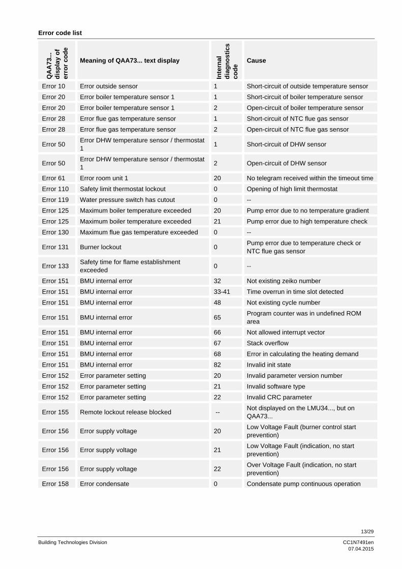
Error code list
QA
A73
...
dis
pla
y o
f e
rro
r co
de
Meaning of QAA73... text display
Inte
rnal
d
iag
no
stic
s c
od
e Cause
Error 10 Error outside sensor 1 Short-circuit of outside temperature sensor
Error 20 Error boiler temperature sensor 1 1 Short-circuit of boiler temperature sensor
Error 20 Error boiler temperature sensor 1 2 Open-circuit of boiler temperature sensor
Error 28 Error flue gas temperature sensor 1 Short-circuit of NTC flue gas sensor
Error 28 Error flue gas temperature sensor 2 Open-circuit of NTC flue gas sensor
Error 50 Error DHW temperature sensor / thermostat 1
1 Short-circuit of DHW sensor
Error 50 Error DHW temperature sensor / thermostat 1
2 Open-circuit of DHW sensor
Error 61 Error room unit 1 20 No telegram received within the timeout time
Error 110 Safety limit thermostat lockout 0 Opening of high limit thermostat
Error 119 Water pressure switch has cutout 0 --
Error 125 Maximum boiler temperature exceeded 20 Pump error due to no temperature gradient
Error 125 Maximum boiler temperature exceeded 21 Pump error due to high temperature check
Error 130 Maximum flue gas temperature exceeded 0 --
Error 131 Burner lockout 0 Pump error due to temperature check or NTC flue gas sensor
Error 133 Safety time for flame establishment exceeded
0 --
Error 151 BMU internal error 32 Not existing zeiko number
Error 151 BMU internal error 33-41 Time overrun in time slot detected
Error 151 BMU internal error 48 Not existing cycle number
Error 151 BMU internal error 65 Program counter was in undefined ROM area
Error 151 BMU internal error 66 Not allowed interrupt vector
Error 151 BMU internal error 67 Stack overflow
Error 151 BMU internal error 68 Error in calculating the heating demand
Error 151 BMU internal error 82 Invalid init state
Error 152 Error parameter setting 20 Invalid parameter version number
Error 152 Error parameter setting 21 Invalid software type
Error 152 Error parameter setting 22 Invalid CRC parameter
Error 155 Remote lockout release blocked -- Not displayed on the LMU34..., but on QAA73...
Error 156 Error supply voltage 20 Low Voltage Fault (burner control start prevention)
Error 156 Error supply voltage 21 Low Voltage Fault (indication, no start prevention)
Error 156 Error supply voltage 22 Over Voltage Fault (indication, no start prevention)
Error 158 Error condensate 0 Condensate pump continuous operation

14/29
Building Technologies Division CC1N7491en 07.04.2015
Error code list (cont’d)
Q
AA
73...
d
isp
lay
of
err
or
cod
e
Meaning of QAA73... text display
Inte
rnal
d
iag
no
stic
s c
od
e Cause
Error 160 Fan speed threshold not reached 20 Under run of minimum fan speed threshold, wrong air supply, retry
Error 160 Fan speed threshold not reached 21 5 times under run of minimum fan speed threshold, wrong air supply, retry after 2 hour
Error 160 Fan speed threshold not reached 22 Fan speed on standstill in standby not reached
Error 160 Fan speed threshold not reached 23 Fan speed threshold in ignition phase not reached
Error 160 Fan speed threshold not reached 24 Fan speed threshold in ignition phase with delayed restart not reached
Error 160 Fan speed threshold not reached 25 Ignition fan speed threshold not reached
Error 161 Maximum fan speed exceeded 20 Exceeding of maximum fan speed NoGmax
Error 164 Error heating circuit flow / pressure switch 1 Pump OFF, but flow / pressure switch does not open
Error 164 Error heating circuit flow / pressure switch 2 Pump ON, but flow / pressure switch does not close
Error 167 Heating power limit exceeded / under run 20 Exceeding maximum heat capacity in operating mode
Error 167 Heating power limit exceeded / under run 21 Under run minimum heat capacity in operating mode
Error 168 Lockout of device active 0 Burner control communication timeout
Error 180 Chimney sweep function active 0 --
Error 181 Regulator stop function active 0 --
Error 183 Remote reset test mode active 20 Remote reset test mode 1 active
Error 183 Remote reset test mode active 21 Remote reset test mode 2 active
Error 193 Flatness test 1 failed 20 Flatness test 1 failed

15/29
Building Technologies Division CC1N7491en 07.04.2015
Parameterization
Parameterization by QAA73 (service tool) (depending on the type of LMU34...): Users Installer / service Features Changing various LMU34... parameters Parameter types Non-safety-related Parameter levels Heating engineer Connection of QAA73 To LMU34... via AGU2.002… The LMU34... can be configured for different applications by setting parameters via the QAA73. To make this procedure easy for the installer, 16 sets of parameters have been defined, every set consisting of 9 parameters, and one set for each application. The installer will only select the particular parameter set he needs. He cannot select single parameters. Only the manufacturer of the LMU34... can define these parameter fields. The boiler manufacturer is able to set the parameters via OCI425 / ACS425.

16/29
Building Technologies Division CC1N7491en 07.04.2015
Parameterization (cont´d)
Parameters and service data that can be edited and viewed in a direct way via the QAA73:
No. OT text Function Access Range Unit
1 TkSmax Max. CH temperature read / write c8_TKSollMin...90 °C
2 THG Summer / winter changeover threshold read / write 10...30 °C
3 Sth1 Slope CH 1 read / write 2...33 ---
4 DtR1 Nominal room adjustment read / write -4.5...4.5 K
5 NhzMax Max. fan speed in CH mode read / write 0...6350 rpm
6 PhzMax Max. modulation in CH mode read / write 0...100 %
7 ZqNach Pump overrun read / write 0...32766 s
8 ZBreMinP Burner min. waiting time read / write 0...6553 s
9 KonfigRg1 Configuration flags read / write 0...255 ---
10 LmodZL_QAA Modulation ignition read / write 0...100 %
11 LmodTL_QAA Min. modulation read / write 0...100 %
12 LmodVL_QAA Max .modulation read / write 0...100 %
13 N_ZL_QAA Nominal fan speed ignition read / write 0...6350 rpm
14 N_TL_QAA Min. nominal fan speed read / write 0...6350 rpm
15 N_VL_QAA Max. nominal fan speed read / write 0...6350 rpm
16 KonfigEingang OT input configuration read / write 0...2 ---
17 Tn_QAA Postpurge time read / write 0...51 s
18 VorgabeLstgLMU Preset output LMU34... read / write 0...100 %
19 ParamID Parameter identification number read --- ---
20 BoilerTyp Boiler type selection read / write 0...15 ---
21 BoilerID Boiler identification read --- ---
22 Stoer1 First previous fault code counter read --- ---
23 Strdia1 First internal previous fault code read --- ---
24 Stoer2 Second previous fault code counter read --- ---
25 Strdia2 Second internal previous fault code read --- ---
26 Stoer3 Third previous fault code counter read --- ---
27 Strdia3 Third internal previous fault code read --- ---
28 Stoer4 Fourth previous fault code counter read --- ---
29 Strdia4 Fourth internal previous fault code read --- ---
30 Stoer5 Fifth previous fault code counter read --- ---
31 Strdia5 Fifth internal previous fault code read --- ---
32 Stoer_akt Actual fault code read --- ---
33 InbetrSetz Startup counter read --- ---
34 SwVers_LMU SW version read --- ---
35 Stralba1 First previous Albatros fault code read --- ---
36 Stralba2 Second previous Albatros fault code read --- ---
37 Stralba3 Third previous Albatros fault code read --- ---
38 Stralba4 Fourth previous Albatros fault code read --- ---
39 Stralba5 Fifth previous Albatros fault code read --- ---
40 Stralba_akt Actual Albatros fault code read --- ---
41 Status_Eingang1 Status input signals LMU34… read --- ---
42 Status_Ausgang1 Status output signals LMU34… read --- ---
Note! Additional parameters via ACS425!

17/29
Building Technologies Division CC1N7491en 07.04.2015
Display of additional service data
Using the CH potentiometer, several internal parameters can be displayed. For activation of this function, the CH potentiometer must be moved from the starting position to the «Display» area, then out of it and back into it again – all within one second. The function will be active 2 seconds later. The CH potentiometer can be used again to set the CH setpoint. It is not necessary to keep it in the «Display» position. While operating the CH potentiometer, the CH setpoint will be displayed. 5 seconds after the last action, the display will show the selected parameter. While activating this function, the actual DHW setpoint will be stored, so DHW requests will be carried out at this setpoint. 10 different parameters can be selected with the DHW potentiometer. When the «Display» function is active and the DHW potentiometer is being operated, the display shows parameter name A0...A9, depending on the position of the DHW potentiometer. After selecting a parameter, the display shows alternatively the parameter name Ax (1 s) and the parameter value (3 s). 10 different values appear on the display, depending on the DHW potentiometer position. A0 DHW position 0: Actual DHW temperature A1 DHW position 1: Outside temperature A2 DHW position 2: Actual PWM value A3 DHW position 3: Actual fan speed A4 DHW position 4: Actual CH setpoint produced by the LMU34... A5 DHW position 5: Flue gas NTC temperature
(not identical with the effective flue gas temperature) A6 DHW position 6: Diagnostic code A7 DHW position 7: Free A8 DHW position 8: Boiler identification A9 DHW position 9: Boiler parameter identification This function stops when the starting sequence on the CH potentiometer is repeated once again, or when there was no action within 3 minutes (timeout). When the function ended by timeout and the CH potentiometer is in the «Display» position, a «d» will appear alternating with the CH temperature (5 s) to remind the user to set the CH setpoint again to a useful value. In this situation, the CH setpoint or room temperature setpoint (depending on the outside sensor) is set to the minimum. The DHW setpoint will then be taken from the actual DHW potentiometer position. This flashing sequence will stop as soon as the CH potentiometer leaves the «Display» position.
DHW potentiometer CH potentiometer
A0
A1
A2
A3A4 A5
A6
A7
A8
A0
max.
min.B
A
749
1z0
2/0
805
max.
min.
Display
Marking of the DHW and CH potentiometers Range A: Chimney sweep or controller stop function, no preheating function *) Range B: No preheating function *) *) Depending on parameterization
CH potentiometer in the «Display» position:
Marking of the potentiometers:

18/29
Building Technologies Division CC1N7491en 07.04.2015
Addendum: Applications
CH and instantaneous DHW heating with 3-port valve: CH and DHW storage tank with heating circuit pump and 3-port valve:
Room thermostat
HC1Heat circuit 1
HC1
Q1CH pump
LMU34...
p
Roomthermostat
DHW start
Boiler 1
Heat circuit 1
instantanous
CH
DHW
Q1
DHW
Motor 3 way valve
M
7491a01e/0107
Primaryheat
exchanger
Room thermostat
HC1Heat circuit 1
HC1
LMU34... Roomthermostat
DHW sensor
Boiler 1
Heat circuit 1
CHDHW
Q1CH pump
Q1
DHW storage tank
Motor 3 way valve
M
DHW sensor
7491a02e/0107
Primaryheat
exchanger
Single heating zone, controlled via 2-positiion room thermostat:
Single heating zone, controlled via room thermostat, weather-dependent heating curve:
HC1Heat circuit 1
DHW
p
Boiler 1
instantanous
H
CHDHW
Q1CH pump
Room thermostat
HC1Heat circuit 1
LMU34...
Roomthermostat
DHW startQ1
External summer / / winter changeover
Motor 3 way valve
7491a03e/0107
Primaryheat
exchanger
HC 1Heat circuit 1
Q1CH pump
DHW
p
Boiler 1
instantanous
H
CH
DHW
OTSOutsidetemperaturessensor
Room thermostat
HC1Heat circuit 1
LMU34...
Roomthermostat
DHW startQ1
External summer /winter changeover
Outsidetemperaturesensor
Motor 3 way valve
7491a04e/0107
Primaryheat
exchanger
19/29
Building Technologies Division CC1N7491en 07.04.2015
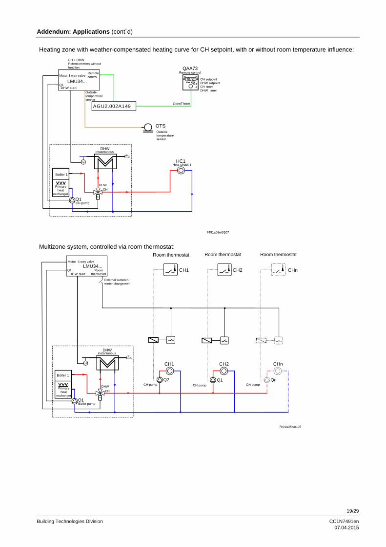
Addendum: Applications (cont´d)
Heating zone with weather-compensated heating curve for CH setpoint, with or without room temperature influence:
LMU34...
Remotecontrol
DHW start
Remote control
20 °C
QAA73
OTSOutsidetemperaturesensor
Outsidetemperaturesensor
OpenTherm
HC1Heat circuit 1
Boiler 1
Q1CH pump
DHW
p
instantanous
H
CHDHW
CH + DHWPotentiometers without function
Q1
AGU2.002A149
Motor 3 way valve
7491a09e/0107
CH setpointDHW setpointCH timerDHW timer
Primaryheat
exchanger
Multizone system, controlled via room thermostat:
CH1
CH1
CH2
CH2
CHn
CHn
Q1Boiler pump
DHW
p
instantanous
H
CH
DHW
Q2CH pump
Q1CH pump
QnCH pump
Boiler 1
LMU34...Room
thermostatDHW startQ1
External summer / winter changeover
Motor 3 way valve
7491a05e/0107
Primaryheat
exchanger
Room thermostat Room thermostat Room thermostat

20/29
Building Technologies Division CC1N7491en 07.04.2015
Addendum: Applications (cont´d)
Multizone system, controlled via room thermostat, with outside sensor:
CH1
CH1
CH2
CH2
CHn
CHn
Q1Boiler pump
DHW
p
instantanous
H
CHDHW
Q2CH pump
Q1CH pump
QnCH pump
Boiler 1
OTS
LMU34...
Outside temperaturesensor
RoomthermostatDHW start
Outsidetemperaturesensor
Q1
Gottak Summer / Winter
Motor 3 way valve
7491a06e/0107
Primaryheat
exchanger
Room thermostat Room thermostat Room thermostat
Multizone system (room thermostat and / or QAA73), zones with weather-compensated CH setpoint, DHW setpoint and DHW time program controlled by QAA73:
OTS
LMU34...
Outside temperature sensor
Remotecontrol
Roomthermostat
DHW start
Boiler 1
Outsidetemperaturesensor
Q1
CH2
CH2
CHn
CHn
Q3CHpump
QnCHpump
CH1
Q2CHpump
AGU2.002A149
Q1Boiler pump
DHWinstantanous
p
H
CH
DHW
Remote controlQAA73
OpenTherm
Motor 3 way valve
7491a10e/0107
Primaryheat
exchanger
20 °CRoom controller CH 1CH timer (MC1)DHW timerDHW setpoint
Room thermostat Room thermostat
External summer / winter changeover for zone 2...n

21/29
Building Technologies Division CC1N7491en 07.04.2015
Connection diagram
AC 120 VAC 230 V
X1
X2
X3
X9
X500
X501
M Time switch heating circuit
Contact time switch
Betriebserde
Fan supply
Gas valve
Heating circuit pump
3 way valve Heating circuit / DHWor condensate pump
1)
1)
Heating circuit pump
DHW pump
Function earth (has to be connected to burner ground independent from X900)Flame (ionization probe)
OFFON
Summer
Winter
Summer / winter /OFF / reset
Burner switch(not at LMU34...)
L **) / L1 *)
N **) / L2 *) N
PE
Room thermostat
Fuse 1
Connector block(not at LMU34...)
N Reset
L Room thermostat IN
X401Flue gas temperature limit thermostat (NTC or contact) not safety relevant
High limit thermostat (safety relevant)
PWM fan interface supply GND (not safety relevant)
PWM hall sensor (fan speed) IN
PWM control output
PWM fan interface supply + (not safety relevant)
Heating circuit temperature sensor
X400
XX
DHW temperature sensor
Outside sensor
DHW flow switch DHW hall sensor / condensate switch
1)1)
Heating circuit flow switch primary (hall or contact)Water pressure switch / bridge (not safety relevant)
X300
Module remote control (AGU2.002...) 1)
X200
PC tool interface (OCI490)
X403 Interface for parameterization IF (OCI425)
X900 Function earth (has to be connected to burner ground independent from X500)
PELV
Fuse 2
1) Depending on the type of LMU34...
Caution! Connection of X500 with X900 – in each case without separate connection to burner ground and protective – with fault, there is a risk of electric shock hazard! *) Applications L1 / L2 are only permitted in EC countries **) Standard application with L / N for EC and U.S.

22/29
Building Technologies Division CC1N7491en 07.04.2015
Connectors list
No. Connector type
Pin code print on PCB
Description LMU34.2… LMU34.3…
X1 Molex 2599 2 poles
HT: Mains supply connector AC 230 V,
50 Hz AC 120 V,
60 Hz
1 LMU34.2…: Mains supply L / L1 ---
1 LMU34.3…: Mains supply L ---
2 LMU34.2…: Mains supply N / L2 ---
2 LMU34.3…: Mains supply N ---
X2 Stelvio CFM / 5 A
HT: Cable length 1 m Cable length 1 m
1 Functional earth (not for protection purposes)
2 Ignition ¹) supply N Half wave rectified AC
max. 3 VA Half wave rectified AC
max. 3 VA
3 PWM mains voltage operated fan supply L AC 230 V max. 160 VA
AC 230 V max. 160 VA 4 PWM mains voltage operated fan supply N
5 Ignition ¹) supply L Half wave rectified AC
max. 3 VA Half wave rectified AC
max. 3 VA
X3 Molex 2599 9 poles
HT: Cable length 1 m Cable length 1 m
1 Gas valve supply L ¹) AC and RAC types cos > 0.5
14 VA
AC types only cos > 0.5
14 VA 2 Gas valve supply N ¹)
3 CH pump supply N or CH + DHW pump N cos >0.9 180 VA
cos > 0.9 95 VA
4 CH pump supply L or CH + DHW pump L
5 3-port valve N or auxiliary relay N 4) 10 VA cos > 0.8
3 poles
4 VA cos > 0.7
3 poles 6 3-port valve CH or auxiliary relay L 4)
7 3-port valve DHW L 4)
8 Reset input N
AC 40 V 50 Hz
< 5 mA cable length 0.5 m
AC 40 V 60 Hz
< 5 mA cable length 0.5 m
9 Room thermostat input L 5 mA (half wave rectified)
Cp < 4000 pF cable length 40 m
5 mA (half wave rectified) Cp < 4000 pF
cable length 40 m
The unit is supplied with the temperature setpoint potentiometer in the OFF position. ¹) Only use components approved by Siemens AG! ²) A special conversion list (hard copy) must be used to retrieve correct measurement values and to set correct threshold values to related functions ³) The fan must meet the requirements of specification LMU5x_TrafoFan_en_V1.2.doc, chapter 3 “Specification for fans with mains voltage operated DC motor” 4) Depending on the type of LMU34...
Note on use of mounted pumps! When using high-efficiency pumps or pumps with integrated electronics, the resulting switch-on currents can adversely affect the relays’ service life. For this reason, use of these types of pump is permitted only if previously authorized in writing by Siemens AG or see AGU2.005.. Data Sheet (N7217).

23/29
Building Technologies Division CC1N7491en 07.04.2015
Connectors list (cont´d)
No. Connector type
Pin code print on PCB
Description LMU34.2... LMU34.3...
X9 Molex 2599 4 poles
HT: Cable length 1 m Cable length 1 m
1 CH timer supply N < 5 mA AC cos = 1
< 5 mA AC cos = 1
2 CH timer contact OUT External voltage-free
contact or bridge in series to room thermostat input
External voltage-free contact or bridge in series to room thermostat input
3 CH timer supply L < 5 mA AC cos = 1
< 5 mA AC cos = 1
4 CH timer contact IN External voltage-free
contact or bridge in series to room thermostat input
External voltage-free contact or bridge in series to room thermostat input
X200 PCB edge connector
PELV: PC tool interface (OCI490...) OCI490... / ACS420 OCI490... / ACS420
1 Internal
2 Internal
3 Internal
4 Internal
5 Internal
X300 4)
Lumberg Duomodul 5 poles
PELV: Auxiliary module (AGU2.002…) for remote control
5 poles cable length <10 cm
5 poles cable length <10 cm
1 Internal
2 Internal
3 Internal
4 Internal
5 Internal The unit is supplied with the temperature setpoint potentiometer in the OFF position. ¹) Only use components approved by Siemens AG! ²) A special conversion list (hard copy) must be used to retrieve correct measurement values and to set correct threshold values to related functions ³) The fan must meet the requirements of specification LMU5x_TrafoFan_en_V1.2.doc, chapter 3 “Specification for fans with mains voltage operated DC motor” 4) Depending on the type of LMU34...

24/29
Building Technologies Division CC1N7491en 07.04.2015
Connectors list (cont´d)
No. Connector
type
Pin code
print on
PCB
Description LMU34.2... LMU34.3...
X400 Lumberg MSF 9 poles
PELV: Cable length 1 m Cable length 1 m
1 DHW temperature sensor NTC 10 k at 25 °C
beta = 3977 DC 5 V
NTC 10 k at 25 °C beta = 3977
DC 5 V
2 Outside temperature sensor NTC 1 k at 25 °C
beta = 3528 cable length 40 m
NTC 1 k at 25 °C beta = 3528
cable lengths 40 m
3 DHW Hall sensor / DHW flow switch IN
Open-circuit condition: Vout = DC 7.5 V
Closed-circuit condition: Iout < 1 mA Uin < 0.5 V
Open-circuit condition: Vout = DC 7.5 V
Closed-circuit condition: Iout < 1 mA Uin < 0.5 V
4 DHW temperature sensor NTC 10 k at 25 °C beta = 3977 max. DC 5 V
NTC 10 k at 25 °C beta = 3977 max. DC 5 V
5 Outside temperature sensor NTC 1 k at 25 °C beta = 3528
cable length 40 m
NTC 1 k at 25 °C beta = 3528
cable length 40 m
6 DHW Hall sensor / DHW flow switch GND GND GND
7 DHW Hall sensor / CH primary flow switch supply
DC 7.5 V (max. 24 mA)
DC 7.5 V (max. 24 mA)
8 CH primary flow switch / water pressure switch / bridge
DC 7.5 V < 2 mA
DC 7.5 V < 2 mA
9 CH primary flow switch / water pressure switch / bridge
GND GND
The unit is supplied with the temperature setpoint potentiometer in the OFF position. ¹) Only use components approved by Siemens AG! ²) A special conversion list (hard copy) must be used to retrieve correct measurement values and to set correct threshold values to related functions ³) The fan must meet the requirements of specification LMU5x_TrafoFan_en_V1.2.doc, chapter 3 “Specification for fans with mains voltage operated DC motor”

25/29
Building Technologies Division CC1N7491en 07.04.2015
Connectors list (cont´d)
No. Connector
type
Pin code
print on
PCB
Description LMU34.2... LMU34.3...
X401 Lumberg
MSF 10 poles PELV: Cable length 1 m Cable length 1 m
1 Flue gas temperature NTC ²) or thermostat
contact
NTC 20 K at 25 °C
beta = 3970
DC 5 V
< 2 mA
NTC 20 k at 25 °C
beta = 3970
DC 5 V
< 2 mA
2 Flue gas temperature NTC ²) or thermostat
contact
NTC 20 K at 25 °C
beta = 3970
DC 5 V
< 2 mA
NTC 20 k at 25 °C
beta = 3970
DC 5 V
< 2 mA
3 High limit thermostat (TB)
Half wave rectified
AC 24 V
I = 2.5...5 mA
Half wave rectified
AC 24 V
I = 2.5...5 mA
4 High limit thermostat (TB)
Half wave rectified
AC 24 V
I = 2.5...5 mA
Half wave rectified
AC 24 V
I = 2.5...5 mA
5 PWM fan interface supply GND ¹) ³) GND GND
6 PWM hall sensor (fan speed) IN (non safety)
¹) ³)
2 rectangular pulses per
revolution
duty ratio 1:1 +/-5 %
2 rectangular pulses per
revolution
duty ratio 1:1 +/-5 %
7 PWM control output (non safety) ¹) ³) 4,800 Hz 4,800 Hz
8 PWM fan interface supply + ¹) ³) DC 30 V DC 30 V
9 CH temperature sensor
NTC 10 k at 25 °C
beta = 3977
DC 5 V
NTC 10 k at 25 °C
beta = 3977
DC 5 V
10 CH temperature sensor
NTC 10 k at 25 °C
beta = 3977
DC 5 V
NTC 10 k at 25 °C
beta = 3977
DC 5 V
X403 Lumberg 3850
4 poles PELV: PARA-IFC (OCI425) OCI425 / ACS425 OCI425 / ACS425
1 Internal
2 Internal
3 Internal
4 Internal
X500 Tabs 6.3 mm HT: Functional earth (burner ground) (not for
protection purposes) Cable length 1 m Cable length 1 m
X501 VT tabs
4.8 mm
HT: Flame (ionization probe) < AC 100 V
cable length 1 m
< AC 100 V
cable length 1 m
X900 Tabs 6.3 mm PELV: Functional earth (burner ground) (not
for protection purposes)
Cable length 1 m Cable length 1 m
The unit is supplied with the temperature setpoint potentiometer in the OFF position. ¹) Only use components approved by Siemens AG! ²) A special conversion list (hard copy) must be used to retrieve correct measurement values and to set correct threshold values to related functions ³) The fan must meet the requirements of specification LMU5x_TrafoFan_en_V1.2.doc, chapter 3 “Specification for fans with mains voltage operated DC motor”

26/29
Building Technologies Division CC1N7491en 07.04.2015
Dimensions
Dimensions in mm
7
34,5
1,5
5
90 52
75
4011
X900
X300 *) X400 X401
X20
0
35
31 20
65
94
87,55 62,5
160
X501
X500
4,2 (6x)
117
127
5
24,95 21,52
17
,5
32,94 17,53
107
,82
80,1
88
5,2
5
*) Depending on the type of LMU34...
5 40
35 45
5
25 20
51
7491
m01
/040
6
16,6
X1
X2
X3
7
8
11
10
9
Terminal Pin Function
X2 7
OpenTherm 8
X3 9
10 11
LMU34...
AGU2.002… (depending on the type of
LMU34...)

27/29
Building Technologies Division CC1N7491en 07.04.2015
Dimensions (cont´d)
Dimensions in mm
15
,945
60
6 51
X501
X500
X900
X300 *)X400 X401
X20
0
*) Depending on the type of LMU34...
Mounting position for AGU2.002… on the LMU34...

28/29
Building Technologies Division CC1N7491en 07.04.2015
Design guide line
Dimensions in mm
9 (6 x)
6 (4 x)
Inclined planefrom 27 up to 54 45
77
62 60Zero point 13
Total height (with AGU2.002... mounted) max. 27
65
33 Total height max. 34
Total height max. 54 (with AGU2.002... mounted)
7491m03e/1006
Area free of components and PCB track
6 51
Zero point
6045
M1:2
With AGU2.002... mountedtotal height of LMU34...circuit printed board max. 15
7491m05e/1006
Component side LMU34…
29/29
Building Technologies Division CC1N7491en 07.04.2015
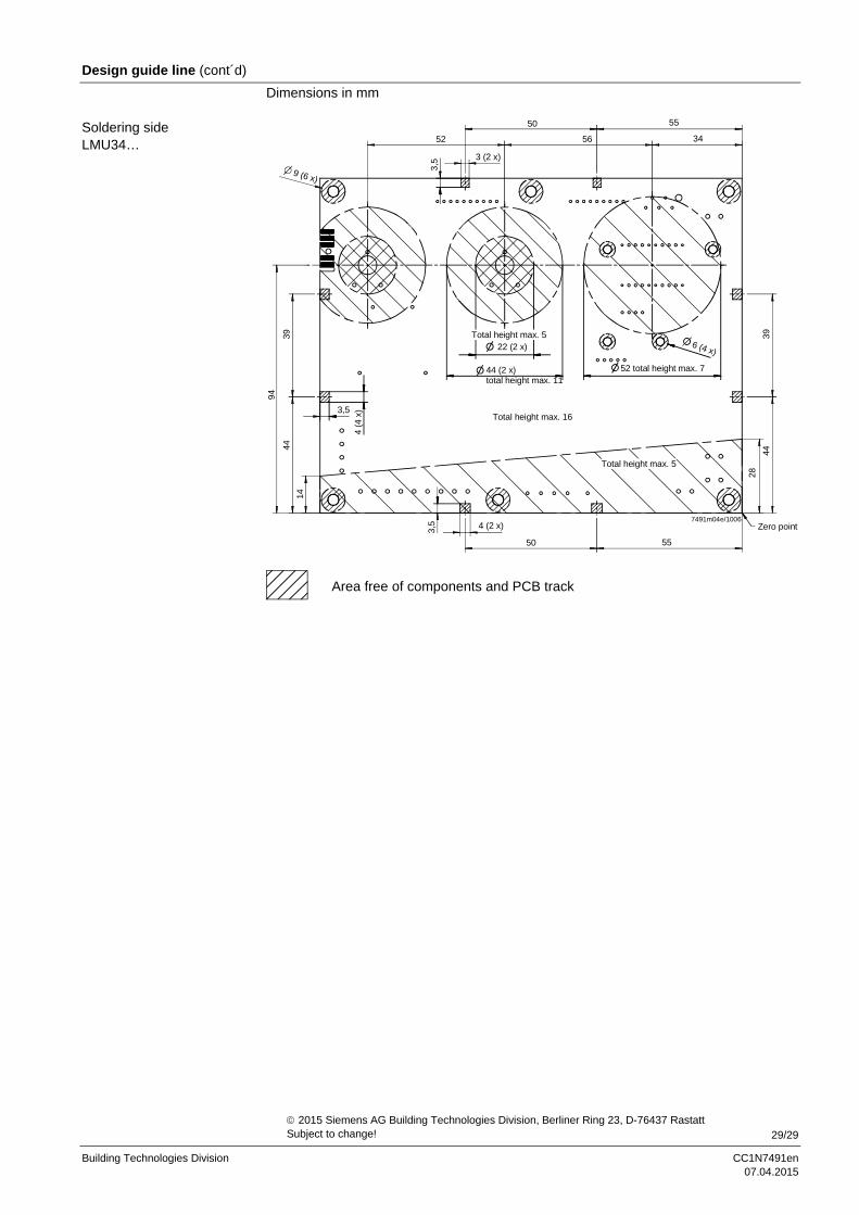
Design guide line (cont´d)
Dimensions in mm
9 (6 x)
50
52
3,5 3 (2 x)
Total height max. 539
94
44
14
3,5
4 (4
x)
3,5 4 (2 x)
50
22 (2 x)
44 (2 x)total height max. 11
Total height max. 16
52 total height max. 7
6 (4 x)
3944
28
Zero point
Total height max. 5
55
55
56 34
7491m04e/1006
Area free of components and PCB track
Soldering side LMU34…
2015 Siemens AG Building Technologies Division, Berliner Ring 23, D-76437 Rastatt Subject to change!