body composition procedures manualnational health and nutrition examination survey body composition...
TRANSCRIPT

National Health and Nutrition Examination Survey
BODY COMPOSITION PROCEDURES
MANUAL
(Revised January 2004)

2
TABLE OF CONTENTS
Chapter Page
1 OVERVIEW OF BODY COMPOSITION....................................................... 1-1
1.1 Overview of Dual Energy X-Ray Absorptiometry .............................. 1-1 1.2 Overview of Bioelectrical Impedance Analysis .................................. 1-1 1.3 Personnel............................................................................................... 1-3
2 EQUIPMENT/SUPPLIES/MATERIALS......................................................... 2-1
2.1 Description of Equipment for DXA..................................................... 2-1
2.1.1 Hologic QDR 4500A............................................................ 2-1 2.1.2 QDR System Operations ..................................................... 2-3 2.1.3 Radiation Badges .................................................................. 2-3
2.2 Maintenance/Repair of Equipment for DXA....................................... 2-3 2.2.1 DXA Bone Densitometer Service Report ............................ 2-4
2.3 Calibration of Equipment for DXA...................................................... 2-4 2.4 Description of Equipment and Supplies for BIA................................. 2-5
2.4.1 Xitron 4200 Bio-Impedance Analyzer ................................. 2-5 2.4.2 MC4200 Measurement Cables ............................................. 2-5 2.4.3 USA CP4200 Power Cord .................................................... 2-5 2.4.4 Xitron IS4000 Disposable Electrode.................................... 2-6 2.4.5 TS4201 Electronic Verification Module.............................. 2-6 2.4.6 BIS4200 Utilities Software .................................................. 2-6
2.5 Maintenance/Repair of Equipment for BIA......................................... 2-7
2.5.1 Xitron Analyzer .................................................................... 2-7 2.5.2 MC4200 Measurement Cables ............................................. 2-7 2.5.3 USA CP4200 Power Cord .................................................... 2-7 2.5.4 Electrodes.............................................................................. 2-8 2.5.5 Repair of Equipment for BIA............................................... 2-8
2.6 Calibration of Equipment for BIA ....................................................... 2-9 2.7 Startup, Shutdown, and Power Failure Procedures ............................ 2-9
3
TABLE OF CONTENTS (continued)
Chapter Page
3 PROTOCOL....................................................................................................... 3-1
3.1 Introduction to the Examination........................................................... 3-1 3.2 Explanation of DXA............................................................................. 3-2 3.3 QDR 4500A System Operation............................................................ 3-3
3.3.1 Startup Procedures for Hologic QDR (Start of Session) ..... 3-3 3.3.2 Shutdown Procedures for QDR (End of Session
Routine Procedure) ............................................................... 3-5
3.4 Procedures for Archiving Whole Body and QC Scans........................ 3-5
3.4.1 End of Session Archive ........................................................ 3-5
3.5 Examinee Preparation for DXA ........................................................... 3-5 3.6 Whole Body DXA Scan ....................................................................... 3-8
3.6.1 Creating an SP Biography .................................................... 3-9 3.6.2 Selecting the Type of Scan................................................... 3-10 3.6.3 Starting the Scan ................................................................... 3-11 3.6.4 Repeating a Scan................................................................... 3-12 3.6.5 Getting Consent for a Second Exam .................................... 3-13 3.6.6 Completing the Second Scan................................................ 3-13
3.7 Explanation of BIA............................................................................... 3-14 3.8 Examinee Preparation for BIA............................................................. 3-14
3.8.1 Body Position for BIA Analysis........................................... 3-15 3.8.2 Electrode Placement for BIA ............................................... 3-15 3.8.3 Whole Body Wrist-Ankle Measurements ............................ 3-16
3.9 DXA Scan Data .................................................................................... 3-18
4 DATA ENTRY SCREENS ............................................................................... 4-1
4.1 Shared Exclusion Questions................................................................. 4-1 4.2 Safety/Exclusion Questions.................................................................. 4-12 4.3 DXA Data Capture Screen ................................................................... 4-22
4.3.1 Getting Permission to Repeat a DXA Scan ......................... 4-26
4.4 DXA Component Status ....................................................................... 4-30 4.5 BIA Data Capture ................................................................................. 4-34

4
TABLE OF CONTENTS (continued)
Chapter Page
4.6 BIA Component Status......................................................................... 4-37 4.7 Session Pickup List............................................................................... 4-39 4.8 Session Preview Report ........................................................................ 4-40 4.9 Room Log ............................................................................................. 4-41 4.10 Close Exam ........................................................................................... 4-42
5 REFERRALS AND REPORT OF FINDINGS ................................................ 5-1
5.1 Observation Referrals ........................................................................... 5-1 5.2 Report of Findings for Body Composition .......................................... 5-3
5.2.1 General Statement for Report of Findings for Body Composition ................................................................ 5-4
5.2.2 Report of Findings Statement for Total Body Fat ............... 5-4 5.2.3 Report of Findings Statement for Total Bone Density ........ 5-4 5.2.4 Report of Findings Statement for T-Score........................... 5-5 5.2.5 Report of Findings Statement if SP Was Excluded
for Safety Reasons ................................................................ 5-6 5.2.6 Sample Preliminary Report of Findings .............................. 5-6
6 QUALITY CONTROL...................................................................................... 6-1
6.1 Equipment and Room Set-Up Checks.................................................. 6-1
6.1.1 Daily...................................................................................... 6-1 6.1.2 Three times per Week (1st, 3rd, and 5th days of work week) 6-2 6.1.3 Weekly .................................................................................. 6-2 6.1.4 Start of Stand ........................................................................ 6-3 6.1.5 End of Stand ......................................................................... 6-3
6.2 Procedures for Completing QC Scans.................................................. 6-3
6.2.1 Hologic Anthropomorphic Spine Phantom (HASP)............ 6-3
6.2.1.1 Checking BMD..................................................... 6-7 6.2.1.2 Checking BMC ..................................................... 6-8 6.2.1.3 Procedures if BMD is not within specifications .. 6-10
6.2.2 Step Phantom ........................................................................ 6-10 6.2.3 Air Scan ................................................................................ 6-12 6.2.4 Slim-line Whole Body Phantom .......................................... 6-13 6.2.5 Circulating HASP (HSP Q-96) ............................................ 6-14 6.2.6 Circulating Block Phantom (Hologic Block Phantom NH #1) 6-15 6.2.7 Hologic Whole Body Phantom ............................................ 6-16

5
TABLE OF CONTENTS (continued)
Chapter Page
6.3 Calibration of Equipment for BIA ....................................................... 6-19
6.3.1 Automatic – Internal Circuitry Self-Check.......................... 6-19 6.3.2 Electronic Circuit Testing with Verification Module.......... 6-19
6.4 QC Scan Checklists .............................................................................. 6-20
6.4.1 Instructions for Completing Weekly QC Scan Checklist .... 6-20 6.4.2 Instructions for Completing Start of Stand QC Scan Checklist ............................................................................... 6-20 6.4.3 Instructions for Accessing Blank QC Checklist Forms....... 6-21
6.5 Data Entry Screens for QC on Equipment ........................................... 6-21
6.5.1 Daily QC Checks .................................................................. 6-23 6.5.2 Weekly QC Checks .............................................................. 6-24 6.5.3 Start of Stand QC Checks..................................................... 6-26 6.5.4 End of Stand QC Checks...................................................... 6-27 6.5.5 Incomplete QC Checks......................................................... 6-27
List of Appendixes
Appendix
A Body Composition (DXA/BIA) Scripts ............................................................ A-1 B Safety/Exclusion Questions (Spanish Translation)........................................... B-1 C Set-up and Tear-down Procedures for Body Composition Room.................... C-1 D DXA Bone Densitometer Report ...................................................................... D-1 E Start of Stand QC Checklist............................................................................... E-1 F Weekly QC Scan Checklist ............................................................................... F-1 G Procedure for Securing the QDR 4500A for Travel ......................................... G-1 H Procedure for Setting Up the QDR 4500A for Operations............................... H-1 I Power Failure Procedures for DXA .................................................................. I-1
6
TABLE OF CONTENTS (continued)
List of Appendixes (continued)
Appendix Page
J Cross Calibration Scans – In -Vivo Whole Body Scans................................... J-1 K Cross Calibration Scans – UCSF VCP-08 ........................................................ K-1
List of Tables
Table
1-1 Age groups and gender for body composition ................................................. 1-3 1-2 Pregnancy status information for body composition by age and gender ......... 1-3
List of Figures
Figure
2-1 Hologic Densitometer QDR4500A ................................................................... 2-1 2-2 Instrument Control Panel on the QDR 4500A .................................................. 2-2 2-3 Laser warning label............................................................................................ 2-2 2-4 Laser locator label.............................................................................................. 2-3 2-5 Xitron Verification Module ............................................................................... 2-6 3-1 Hologic power module right side panel ............................................................ 3-3 3-2 Instrument control panel .................................................................................... 3-6 3-3 Scan table mattress (top view)........................................................................... 3-7 3-4 Hologic selections screen: whole body scan ..................................................... 3-8 3-5 Patient selections menu...................................................................................... 3-9 3-6 Patient biography information ........................................................................... 3-9 3-7 Scan selections menu ......................................................................................... 3-10

7
TABLE OF CONTENTS (continued)
List of Figures (continued)
Figure Page
3-8 Total body scan image ....................................................................................... 3-11 3-9 Body position and electrode placement............................................................. 3-15 3-10 Electrode placement........................................................................................... 3-16 3-11 BIA data capture ................................................................................................ 3-17 3-12 Data displayed after analysis (1) ....................................................................... 3-18 3-13 Data displayed after analysis (2) ....................................................................... 3-19 4-1 Shared exclusion questions (1) .......................................................................... 4-1 4-2 Shared exclusion questions (amputations 1) ..................................................... 4-2 4-3 Shared exclusion questions (amputations 2) ..................................................... 4-3 4-4 Shared exclusion questions (amputations 3) ..................................................... 4-4 4-5 Shared exclusion questions (weight 1) .............................................................. 4-5 4-6 Shared exclusion questions (weight 2) .............................................................. 4-6 4-7 Shared exclusion questions (weight 3) .............................................................. 4-7 4-8 Shared exclusion questions (pacemaker or automatic defibrillator)................. 4-8 4-9 Shared exclusion questions (pregnancy 1) ........................................................ 4-9 4-10 Shared exclusion questions (pregnancy 2) ........................................................ 4-10 4-11 Shared exclusion questions (no exclusions)...................................................... 4-10 4-12 Shared exclusion questions (required response) ............................................... 4-11 4-13 Safety/exclusion questions (1)........................................................................... 4-12 4-14 Safety/exclusion questions (2)........................................................................... 4-13 4-15 Safety/exclusion questions................................................................................. 4-14

8
TABLE OF CONTENTS (continued)
List of Figures (continued)
Figure Page
4-16 Safety/exclusion questions (amputations) ......................................................... 4-15 4-17 Safety/exclusion questions (artificial joints) ..................................................... 4-16 4-18 Safety/exclusion questions (hearing aid)........................................................... 4-17 4-19 Safety/exclusion questions (coronary stents) .................................................... 4-18 4-20 Safety/exclusion questions (contrast radiography) ........................................... 4-19 4-21 Safety/exclusion questions (nuclear medicine studies)..................................... 4-20 4-22 Safety/exclusion questions (required entry) ...................................................... 4-21 4-23 Safety/exclusion questions (don’t know) .......................................................... 4-21 4-24 DXA data capture (1)......................................................................................... 4-22 4-25 DXA data capture (2)......................................................................................... 4-23 4-26 DXA data capture (comments on scan)............................................................. 4-24 4-27 DXA data capture (scan not completed) ........................................................... 4-25 4-28 DXA data capture (consent for second scan) .................................................... 4-26 4-29 DXA data capture – second scan completed – (1) ............................................ 4-27 4-30 DXA data capture – second scan completed – (2) ............................................ 4-28 4-31 DXA data capture (second scan permission not given) .................................... 4-29 4-32 DXA component status (1) ................................................................................ 4-30 4-33 DXA component status (2) ................................................................................ 4-31 4-34 DXA component status (3) ................................................................................ 4-32 4-35 DXA component status (required comments)................................................... 4-33 4-36 BIA data capture (1)........................................................................................... 4-34

9
TABLE OF CONTENTS (continued)
List of Figures (continued)
Figure Page
4-37 BIA data capture (2)........................................................................................... 4-35 4-38 BIA data capture (3)........................................................................................... 4-36 4-39 BIA component status (1) .................................................................................. 4-37 4-40 BIA component status (2) .................................................................................. 4-38 4-41 Session preview.................................................................................................. 4-39 4-42 Session Preview Report ..................................................................................... 4-40 4-43 Room log for body composition........................................................................ 4-41 4-44 Close exam ......................................................................................................... 4-42 5-1 Menu to select observation referral ................................................................... 5-1 5-2 Pick list of SPs in current session...................................................................... 5-2 5-3 Observation referral in body composition......................................................... 5-2 5-4 Observation referral from other components in physician's referral review box ............................................................................................. 5-3 5-5 Sample Preliminary Report of Findings for all SPs > 20 years of age ............ 5-6 5-6 Sample Preliminary Report of Findings for male SPs < 17 years of age ........ 5-7 6-1 Main selections menu ........................................................................................ 6-4 6-2 Spine phantom quality control .......................................................................... 6-4 6-3 Warning message for step phantom. ................................................................. 6-5 6-4 Spine phantom QC image .................................................................................. 6-6 6-5 Spine phantom QC............................................................................................. 6-6 6-6 Spine phantom QC – plot for BMD .................................................................. 6-7

10
TABLE OF CONTENTS (continued)
List of Figures (continued)
Figure Page
6-7 Spine phantom QC selections screen ................................................................ 6-8 6-8 Spine phantom QC options screen..................................................................... 6-8 6-9 Spine phantom QC – parameters to plot ........................................................... 6-9 6-10 Spine phantom QC – plot for BMC................................................................... 6-9 6-11 Step phantom QC setup screen .......................................................................... 6-11 6-12 Step phantom QC – completed .......................................................................... 6-11 6-13 Slim-line Whole Body Phantom fully assembled ............................................. 6-13 6-14 Layout of whole body phantom – top view....................................................... 6-18 6-15 Layout of whole body phantom – side view ..................................................... 6-18 6-16 Quality control reminder message box.............................................................. 6-21 6-17 Utilities menu to select quality control.............................................................. 6-22 6-18 Quality control log-on........................................................................................ 6-22 6-19 Quality control daily checks (1) ........................................................................ 6-23 6-20 Quality control daily checks (2) ........................................................................ 6-23 6-21 Quality control weekly checks (1)..................................................................... 6-24 6-22 Quality control weekly checks (2)..................................................................... 6-25 6-23 Quality control weekly checks (3)..................................................................... 6-25 6-24 Quality control stand checks (1) ........................................................................ 6-26 6-25 Quality control stand checks (2) ........................................................................ 6-26 6-26 Quality control end of stand check .................................................................... 6-27 6-27 Quality control incomplete entry ....................................................................... 6-28

1-11
1. OVERVIEW OF BODY COMPOSITION
Body composition will be evaluated in the current NHANES by anthropometry, dual energy X-ray absorptiometry (DXA) and bioelectrical impedance analysis (BIA). These methods will be used to (1) monitor secular trends in overweight prevalence; (2) describe the prevalence of obesity; and (3)
examine the relationship between overweight and obesity and other examination measures, including blood pressure, glucose intolerance, and a battery of indicators for cardiovascular disease. Concurrent measurement of BIA and DXA will allow development of equations to estimate body composition using BIA from a national sample. This component will use two methods to assess body composition - DXA
and BIA.
1.1 Overview of Dual Energy X-Ray Absorptiometry
DXA will be used to assess overall skeletal changes that often occur with age by measuring bone mineral content (BMC) and bone mineral density (BMD). In addition, total body fat and lean muscle mass measurements can give insight into the influence of age, sex, and race/ethnicity on the skeleton
relative to these measures. DXA measurements can be used to determine the prevalence of osteopenia and osteoporosis. DXA measurements can also be used to provide information on early gender and ethnic changes in the rate of bone accretion and to determine the age when skeletal accretion ceases and when peak bone mass occurs. This information can be used to implement effective and timely measures with
the objective of maximizing peak bone mass. Such measures may include calcium supplementation, dietary fortification, or programs promoting dairy products and other calcium and vitamin D rich foods. This information can also be used to assess the impact of factors such as diet or lifestyle on measures of bone status in various minority populations.
1.2 Overview of Bioelectrical Impedance Analysis
BIA is a method that is used to estimate body composition. BIA measures the electrical impedance of body tissues and has been used to assess fluid volumes, total body water, body cell mass, and fat-free body mass. A small alternating electrical current is passed through surface electrodes placed on a hand and foot and the impedance to the current flow is measured by different electrodes placed
adjacent to the injection electrodes. The voltage drop between electrodes provides a measure of impedance.

1-12
Impedance is the opposition to flow of an electric current. In human tissue, impedance is proportional to total body water. Impedance is high in fat tissue and low in lean tissue. Nonfat or lean tissue, where intracellular fluid and electrolytes are mainly found, is highly conductive and has limited resistance to alternating electrical current compared with fat tissue, which contains very little fluid and
has high resistance to electrical current. The cell membrane consists of a nonconductive double layer of phospholipids between two layers of conductive protein molecules. The impedance of tissues is comprised of resistance and reactance. The resistive component is provided by the conductive characteristics of body fluids, whereas the cell membranes, acting as imperfect capacitors, provide the
reactive component. In human tissue, impedance is affected by the frequency of the flow of current. At low
frequencies, there is minimal conduction through the cell membrane due to the high capacitance of the
membrane. Mainly the extracellular water influences the impedance at low frequencies. At high frequencies, the capacitance of the membrane decreases and the current flows equally through both the extracellular water and the intracellular water. Impedance measures made over a range from low to high frequencies allow development of prediction equations relating impedance measures to extracellular fluid
at low frequencies and to total body water at high frequencies. This is known as multifrequency bioelectrical impedance analysis. Lean body mass can be calculated based on an assumed hydration fraction for lean tissue and from this calculation, fat mass can also be calculated.
In NHANES, multifrequency BIA will be performed on all individuals 8 through 49 years. The DXA exam will be completed on all individuals 8 years and above. See Table 1-1. Pregnancy status will be assessed on all females 12 through 59 years and menstruating 8- to 11-year-olds. If the result of the pregnancy test is positive, the SP will be excluded from the entire exam. If a pregnancy test for an SP
who is 8-17 years comes back positive, a second test will be done for confirmation. In addition, women aged 12 through 59 years will be asked to self-report their pregnancy status and will be excluded if they respond yes even if the pregnancy test was negative. Self-report on pregnancy status for 12-17 year old females will be asked in the Physician’s Exam. Females 8 through 11 years of age will not be asked about
pregnancy status. See Table 1-2.
Table 1-1. Age groups and gender for body composition
Component Age Gender
DXA 8 years and above Males & Females
BIA 8 through 49 years Males & Females

1-13
Table 1-2. Pregnancy status information for body composition by age and gender
Pregnancy Status Age Gender
Pregnancy Status - Urine Test 12 through 59 years Females
Pregnancy Status - Urine Test Menstruating 8-11 years Females
Pregnancy Status -Self Report 12 through 59 years Females
Pregnancy Status -Self Report (Asked in Physician’s Exam)
12-17 years Females
Pregnancy Status -Self Report (Asked in Body Composition Exam)
18 through 59 years Females
1.3 Personnel
The health technician will measure BIA and DXA in the same room. DXA will be measured
first, followed by BIA. The health technician will be responsible for performing the tests and for the maintenance and calibration of the equipment and supplies.

2. EQUIPMENT/SUPPLIES/MATERIALS
2.1 Description of Equipment for DXA
2.1.1 Hologic QDR 4500A
The Hologic QDR 4500A (Figure 2-1) is a fan beam X-ray bone densitometer which uses two different energy levels produced by an energy tube to estimate bone mineral content (BMC) and bone mineral density (BMD). The QDR uses a low level of X-rays and under standard operating conditions the
entrance dose to the examinee for a whole body scan is less than 1 mR (a standard X-ray is approximately 35 mR).
Figure 2-1. Hologic Densitometer QDR4500A
The densitometer produces ionizing radiation in the form of X-rays and uses laser radiation
to position scans; however, the radiation exposure is so low that no shielding of the room or of health technicians is required.
The X-ray ON Indicator is an amber light located in the lower right corner of the instrument
control panel (see Figure 2-2). When the X-ray lamp is lit, X-rays are being produced.
2-14

The Emergency Stop Button is a round red button at the right end of the instrument control panel that is used for emergencies. When this button is pressed, the X-rays and the table are disabled and scanning stops immediately. Pulling on the button resumes normal operation.
! Press down on the button to stop the scan
! Pull up on the button to resume normal operation.
Figure 2-2. Instrument Control Panel on the QDR 4500A
Laser Positioning - The Laser-On Lamp is an amber light above the Laser switch on the
Instrument Control Panel. It alerts the user that the laser position indicator is active. The laser position indicator unit produces 1 mW laser emission. The examinee and technician should avoid looking directly into the beam, or placing reflective objects in the path of the beam.
The QDR 4500 Elite includes a laser safety feature that turns the laser off if the distance between the top (right side) of the table is less than approximately 15.5 inches from the laser light spot. This feature is there to help prevent shining the laser light in the examinee’s eyes. Figure 2-3 shows the laser warning label located on the scanner arm.
2-15
Figure 2-3. Laser warning label
Arrows marked Laser Aperture mounted on the scanner arm note the location of the laser beam. Figure 2-4 shows the laser locator label.

Figure 2-4. Laser locator label
2.1.2 QDR System Operations (See Section 3.3)
See Section 3.3 for Start-up and Shut-down Procedures for the QDR System. See Appendix I for Power Failure Procedures.
2.1.3 Radiation Badges
Health technicians operating the densitometers are required to wear radiation badges for dosimetry processing. A control badge is placed in the room on the computer cart beside the densitometer.
2.2 Maintenance/Repair of Equipment for DXA
If the Chief Technician needs to contact Hologic for repair, the contact numbers are listed below:
! Call Hologic customer support at 1-800-321-4659.
! You will need the model number and the serial number for your machine.
! Model number for all MECs is QDR 4500.
! Serial number for MEC 1 is 45575.
! Serial number for MEC 2 is 45678.
! Serial number for MEC 3 is 45700.
2-16

2-17
2.2.1 DXA Bone Densitometer Service Report
When the Hologic densitometer is serviced or repaired:
! The Chief Technician will complete a ‘DXA Bone Densitometer Report.’ (See
Appendix D).
! Fax a copy of the report to the Home Office. See Appendix D for specific instructions about names and numbers. The Home Office will send this to the Quality Control Reading Laboratory.
! Fax a copy of the service report completed by the service engineer to the Home Office when the repair or service is made.
! Put a copy of the service engineer’s report and a copy of the DXA Bone Densitometer in the service report binder kept in the DXA room. This binder is used to store the Hologic Customer Service Reports and the DXA Bone Densitometer Service Report forms.
! Blank DXA Bone Densitometer Service Report Forms are stored electronically in the ISIS system. Open Word, select File/Open, look in the directory for Mecstaff/Blank forms/DXA_serv.doc.
2.3 Calibration of Equipment for DXA
Refer to Chapter 6 for complete instructions regarding calibration and quality control scanning procedures.
2.4 Description of Equipment and Supplies for BIA
2.4.1 Xitron 4200 Bio-Impedance Analyzer
The analyzer used in this survey is the HYDRA ECF/ICF Bio-Impedance Spectrum Analyzer (Model 4200) manufactured by Xitron Technologies, Inc, San Diego, California. This multi-frequency analyzer uses a full 12 bit digital signal processing technique to measure impedance at 50 frequencies logarithmically spaced from 5 kHz to 1 MHz. It is used to measure extracellular fluid (ECF)
and intracellular fluid (ICF). The measured raw spectral data are fit to the Cole biophysical model using least squares nonlinear curve fitting, and Cole model terms RE and RI are used in an equation derived from

2-18
Hanai mixture theory to predict ECF and ICF volume. Total body water (TBW) and Fat-Free Mass (FFM) are then calculated as ECF + ICF, assuming the FFM to be 73.2% TBW.
The Hydra ECF/ICF has an RS232 Serial Port to allow transmission of raw data directly to
the ISIS system. The analyzer measures resistance (R) and reactance (X) and calculates the reciprocal impedance (Z) and phase angle (2) at each measured frequency.
2.4.2 MC4200 Measurement Cables
Only these measurement cables should be used with the Hydra ECF/ICF because the accuracy specifications are only valid using this cable set. Do not attempt to modify or repair the cables.
Report any problem to the coordinator.
2.4.3 USA CP4200 Power Cord
The CP4200 power cord is a USA medical grade power cord designed to plug directly into the line and the device. Use of other power cords can cause the product to no longer meet the applicable safety standards.
2.4.4 Xitron IS4000 Disposable Electrode
Obtaining accurate measurements with the Hydra ECF/ICF requires the use of appropriate conductive electrodes. High quality surface gum-based electrodes with at least 5 cm2 in total surface area will be used. The Xitron IS4000 Disposable Electrode, which has nearly double the surface area of conventional electrodes, has been made specifically for the device to ensure reduced contact resistance.
Two black current-injection electrodes (I) are placed on the right hand and foot and two red voltage-detector electrodes (V) will be placed on the right ankle and wrist.
2.4.5 TS4201 Electronic Verification Module
The electronic verification module will be used to test the device performance and functionality. (See Figure 2-5 and Section 6.3.2 in Chapter 6.)

Figure 2-5. Xitron Verification Module
2.4.6 BIS4200 Utilities Software
This software will be used to collect data from the Xitron HYDRA ECF/ICF Bio-Impedance
Analyzer and directly interface with the Integrated Survey Information System (ISIS).
2.5 Maintenance/Repair of Equipment for BIA
2.5.1 Xitron Analyzer
Clean the external surfaces of the chassis using a mild detergent and soft damp cloth. Do not
use a freon-based cleaning solution on the front panel. Do not allow excessive moisture to enter the chassis during the cleaning. If the external surfaces become excessively dirty or damaged, contact the MEC manager who should contact Westat and Xitron Technologies for details as to how to rectify this situation.
2.5.2 MC4200 Measurement Cables
The following checks on the measurement cables should be made at least weekly. ! Inspect for cracks, splits, or kinks in the cable and connectors.
2-19

2-20
! Replace the cables if any of these conditions exist.
! Ensure the rear panel “pins” are straight and connecting properly.
! Ensure that the spring in the alligator clips that attach to the surface electrodes is functioning properly and that they close tightly on the electrodes.
! Clean alligator clips with alcohol pads. Remove any electrode “gum” that may have collected.
! Scrape the teeth of the alligator clips to remove any build-up of tarnish or corrosion that inhibits conductivity.
2.5.3 USA CP4200 Power Cord
Every Stand
! Check power cord and connectors for cracks and splits in the external insulation.
! Replace power cord if any of these conditions exist.
! Ensure the rear panel “pins” are straight and connecting properly.
! Ensure that the ends of the power cord are free of dirt and grime.
2.5.4 Electrodes
General
! Reseal unused electrodes in airtight foil bag or container.
! Do not reuse electrodes.
! Do not use electrodes that are out of date or have been left out in the open for an extended period.
! Store electrodes in a cool, dry place.
2.5.5 Repair of Equipment for BIA
! If equipment is in need of repair - do not attempt to repair it. Attempted repair by an unqualified person may void the warranty.
! Notify the MEC manager.

2-21
! Include model number of the analyzer, serial number, and a detailed description of the nature of the problem.
- Xitron Technologies, Inc
- 9770-A Carrol Centre Road
- San Diego, CA 92126
- Phone 858-530-8099
- Fax 858-530-8077
- E-mail: [email protected]
2.6 Calibration of Equipment for BIA
Refer to Chapter 6 for a complete explanation of the BIA calibration procedures.
2.7 Startup, Shutdown, and Power Failure Procedures
Refer to Appendix G for the procedures for securing the QDR 4500A for travel. Refer to Appendix H for the procedures for setting up the QDR 4500A for operations. Refer to Appendix I for power failure procedures for DXA.
Refer to Section 3.3 for daily startup and shutdown procedures.
3-22
3. PROTOCOL
3.1 Introduction to the Examination
The technician should briefly explain the examination when the sample person (SP) is
brought into the room. The exam should be explained in more detail as each section is being completed. The objective is to inform the SP about the exam and to position the SP as quickly as possible. Below is a suggested introductory script but the examiner should use his/her own words for this explanation. This is an explanation, not a standard script, so the technician may adjust the explanation to the level of
understanding of the examinee.
Suggested Introduction to Component (Not a Standard Script)
“In this room we are going to do two exams. One exam can tell us something about how strong your bones are and how much body fat you have. The other exam measures the amount of water in your body. I will explain each exam in more detail as I do it. Please lie down on the table and get as
comfortable as possible. I am going to ask you a few questions before I start the exam.”
Suggested Introduction to Component (Not a Standard Script): Spanish Version
“En este cuarto vamos a hacer dos exámenes. Un examen nos puede decir algo acerca de qué tan fuerte están sus huesos y cuanta grasa tiene en el cuerpo. El otro examen mide la cantidad de agua que tiene en el cuerpo. Explicaré cada examen con mayor detalle mientras los haga. Por favor acuéstese en la
mesa y póngase tan cómodo como sea posible. Le voy a hacer algunas preguntas antes de empezar el examen.”
3.2 Explanation of DXA
The technician is positioning the examinee during this explanation. This should be used as a guideline only and the technician should adjust the explanation to the level of understanding of the SP.
The script used for an 8-year-old will be different from the script used for a 60-year-old.

3-23
Suggested Explanation of DXA (Not a Standard Script)
“For this examination I will be doing a scan of your body with this machine. The exam lasts 3 minutes and you will not feel anything except for the table movement. I need you to lie straight on the
table with your hands by your sides. I am attaching this Velcro strap around your feet to hold them in this position for the exam. As the machine scans your body, the table will move up and down and back and forth. This arm (the C-arm) will also be moving.
In order to ensure that you receive a good quality scan, please check all of your pockets once more for any items that you may have forgotten and for watches and jewelry. It is important that you remain perfectly still during the scan.” If the SP is a female, add: “Please make sure that your bra has been removed.”
Suggested Explanation of DXA (Not a Standard Script): Spanish Version
“Para este examen le haré un escáner del cuerpo con esta máquina. El examen dura tres minutos y usted no sentirá nada excepto el movimiento de la mesa. Necesito que se acueste derecho en la mesa con las manos a los lados. Le estoy poniendo esta cinta “Velcro” alrededor de los pies para mantenerlos en esta posición durante el examen. A medida que la máquina explore su cuerpo, la mesa se
moverá hacia arriba y hacia abajo y de atrás para delante. Este brazo (el C-arm) también se estará moviendo.”
Con el propósito de asegurarnos de que se le hará un escáner de buena calidad, por favor
revise sus bolsillos una vez más para revisar cualquier cosa que se le haya olvidado, así como relojes y joyas. Es importante que se quede perfectamente quieto(a) durante el escáner. IF THE SP IS A FEMALE, ADD: “Por favor asegúrese de quitarse el sostén/brasier.”

3.3 QDR 4500A System Operation The QDR 4500 system should be turned on at the beginning of the day and off at the end of
each session for that day. See Appendix H for setting up the QDR 4500 for operations. Routine startup
procedures for the beginning of a session are outlined below in Section 3.3.1. See Appendix G for securing the QDR 4500 for travel. Routine shutdown procedures are outlined in Section 3.3.2. See Appendix I for power failure procedures for DXA.
3.3.1 Startup Procedures for Hologic QDR (Start of Session)
Confirm these settings first.
! Check that the POWER ON lamp on the Power Module is lit. (The switch and the lamp are located on the bottom left of the back panel. This light indicates that the system is in standby mode and power is maintained to the signal detector. This eliminates warming up the detector when the system is turned on. This should be left on at all times unless a power failure occurs. See Appendix I for Power Failure Procedures.
! Check that the INSTRUMENT POWER switch (2) on the Power Module right side panel is in the ON position.
! X-RAY ENABLE KEY (3) should be OFF. See Figure 3-1.
3-24
Figure 3-1. Hologic power module right side panel
3-25
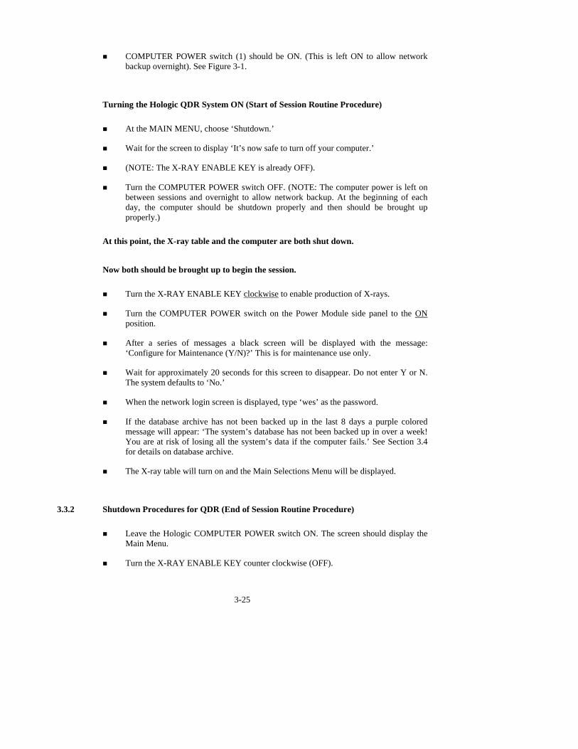
! COMPUTER POWER switch (1) should be ON. (This is left ON to allow network backup overnight). See Figure 3-1.
Turning the Hologic QDR System ON (Start of Session Routine Procedure)
! At the MAIN MENU, choose ‘Shutdown.’
! Wait for the screen to display ‘It’s now safe to turn off your computer.’
! (NOTE: The X-RAY ENABLE KEY is already OFF).
! Turn the COMPUTER POWER switch OFF. (NOTE: The computer power is left on between sessions and overnight to allow network backup. At the beginning of each day, the computer should be shutdown properly and then should be brought up properly.)
At this point, the X-ray table and the computer are both shut down.
Now both should be brought up to begin the session.
! Turn the X-RAY ENABLE KEY clockwise to enable production of X-rays.
! Turn the COMPUTER POWER switch on the Power Module side panel to the ON position.
! After a series of messages a black screen will be displayed with the message: ‘Configure for Maintenance (Y/N)?’ This is for maintenance use only.
! Wait for approximately 20 seconds for this screen to disappear. Do not enter Y or N. The system defaults to ‘No.’
! When the network login screen is displayed, type ‘wes’ as the password.
! If the database archive has not been backed up in the last 8 days a purple colored message will appear: ‘The system’s database has not been backed up in over a week! You are at risk of losing all the system’s data if the computer fails.’ See Section 3.4 for details on database archive.
! The X-ray table will turn on and the Main Selections Menu will be displayed.
3.3.2 Shutdown Procedures for QDR (End of Session Routine Procedure)
! Leave the Hologic COMPUTER POWER switch ON. The screen should display the Main Menu.
! Turn the X-RAY ENABLE KEY counter clockwise (OFF).

3-26
! Remove the key and put it in the designated spot.
3.4 Procedures for Archiving Whole Body and QC Scans
Body scans and phantom scans will be archived at the end of each session. Database Archive and Quality Control Archive will be completed on a weekly basis.
3.4.1 End of Session Archive
! Archive scans completed in the session.
! Archive all QC scans (spine, step, airscan, circulating phantoms, and whole body phantoms)
Procedure for archiving scans:
! Highlight ‘Archive’ and press ‘Enter.’
! Highlight each scan to be archived and press the + key to mark the scan for archive. (Highlight a scan and press the ‘-’ key to remove a scan from the archive list.
! When all the scans (SP scans and QC scans) have been marked with a ‘+’, press ‘Enter’ to archive the scans.
! The number on the top left hand corner of the blue screen displays the number of the scans selected for archive and counts down the scans as they are archived.
3.5 Examinee Preparation for DXA
The SP should be logged into the exam as soon as possible after he/she has entered the room. If the SP is greater than 6’5”, he/she will be excluded from Body Composition due to
limitations of the table and room size. A marker on the wall inside the room is placed at 6’5”. When the SP enters the Body Composition room, check their height against this marker. If the height exceeds this limit, the SP is excluded from BIA and DXA. On the first ISIS screen in the Body Composition application, select ‘Close.’ The status will be set to ‘Not Done’ due to ‘height limitation on the table.’
If the SP’s weight is more than 300 pounds, he/she will be excluded from Body Composition
due to weight limitation of the table. If the SP appears to be greater than 300 pounds, ask them to step on

the scales. If he/she is greater than 300 pounds, open up the exam for this SP and proceed through the shared exclusion questions. These questions will exclude the SP from the exam. See Section 4.1.
Have the SP remove all metal objects from their body (jewelry, belts, snaps, underwire bras).
If they have small objects such as rings that will not come off, mark “No, OK to continue” and proceed with the exam. (Inability or refusal to remove jewelry is an exclusion for BIA but not for DXA; however, the SP should be encouraged to remove all metal objects if possible.) False teeth and hearing aids do not have to be removed.
Before moving the table or C-Arm: ! Confirm that the runner area of the table is clear of objects that might interfere with
table movement; and
! Check that the table scan area is clear of articles that might interfere with table movement.
Press the Patient ON/OFF switch on the Control Panel of the Hologic densitometer to allow
the C-arm to move to the far left and extend the table out from the base. See Figure 3-2. This will make it easier for the SP to get on (or off) the table.
Figure 3-2. Instrument control panel
3-27
! After the C-arm and table stop moving, assist the SP onto the table and have him/her lie down on their back with their head to your right as you face the table.
! Press the ‘Center’ switch on the Control Panel, and wait for the C-arm to position itself to the center of the table.
! Make sure the SP is in the center of the table with respect to the center lines at the head and foot of the pad.
! Confirm that the SP is lying straight on the table. One method to check this is to position yourself at the foot of the table and look at the alignment of the body. Visualize a straight line from the nose, center of the body, and down through the knees and toes.
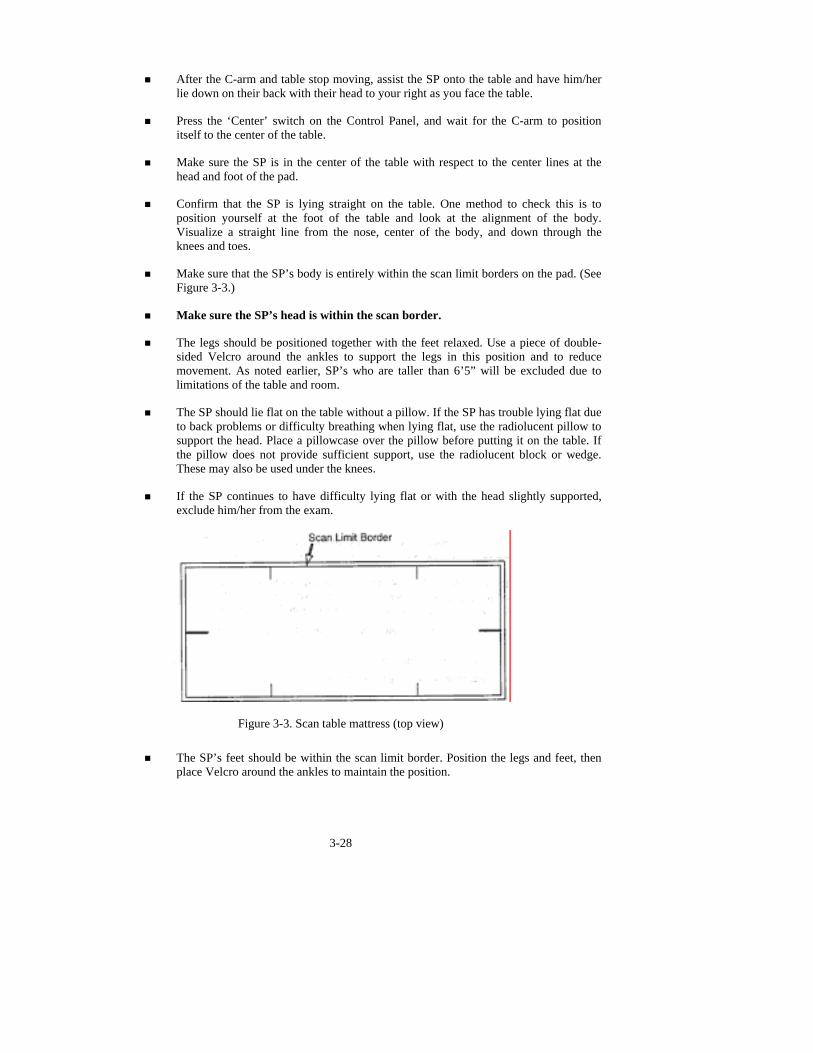
! Make sure that the SP’s body is entirely within the scan limit borders on the pad. (See Figure 3-3.)
! Make sure the SP’s head is within the scan border.
! The legs should be positioned together with the feet relaxed. Use a piece of double-sided Velcro around the ankles to support the legs in this position and to reduce movement. As noted earlier, SP’s who are taller than 6’5” will be excluded due to limitations of the table and room.
! The SP should lie flat on the table without a pillow. If the SP has trouble lying flat due to back problems or difficulty breathing when lying flat, use the radiolucent pillow to support the head. Place a pillowcase over the pillow before putting it on the table. If the pillow does not provide sufficient support, use the radiolucent block or wedge. These may also be used under the knees.
! If the SP continues to have difficulty lying flat or with the head slightly supported, exclude him/her from the exam.
3-28
Figure 3-3. Scan table mattress (top view)
! The SP’s feet should be within the scan limit border. Position the legs and feet, then
place Velcro around the ankles to maintain the position.

! Place the SP’s arms straight at their sides, palms down, with a separation from the thighs. Verify that the arms are within the scan border. A large SP can place their hands vertically next to their thighs to ensure that hands and arms remain within the limits. Do not tuck the hands under the body.
! There must be a space between the patient’s arms and sides whenever possible.
3.6 Whole Body DXA Scan
! Go to the Hologic ‘Selections’ screen (Figure 3-4).
! At the ‘Selections’ menu, select ‘biography’ to enter a new SP ID.
! You can select ‘biography’ by typing ‘P’ or by highlighting biography and pressing ‘enter.’
Figure 3-4. Hologic selections screen: whole body scan
3-29

3.6.1 Creating an SP Biography
! At the ‘Patient Selections’ menu, press ‘Insert’ to create a new SP biography. See Figure 3-5.
Figure 3-5. Patient selections menu
! Pressing ‘Insert’ brings you to the patient biography information screen. See Figure 3-6.
! Enter the SP ID in the ‘Name’ field. Enter your initials in the ‘Operator’ field.
! Enter the SP’s date of birth in the ‘DOB’ field.
3-30
SP ID in Name Field
Figure 3-6. Patient biography information

! Enter the SP’s sex in the ‘Sex’ field.
! Press <F10> to advance to the next screen. (Press Esc to go back to the previous menu if necessary.)
! If the data have been entered previously, this screen can be accessed through ‘Biography’ on the ‘Selections’ menu.
! The data on this screen can be edited by pressing F8.
! Press Esc to return to the Hologic Selections screen. (see Figure 3-4).
! Highlight ‘Select’ and press enter (or press E) to bring up the ‘Patient Selections’ menu.
! The ‘Patient Selections’ menu appears (see Figure 3-5).
! The new SP is now in the list of SPs.
! Highlight this name and press ‘Enter.’
3.6.2 Selecting the Type of Scan
! The ‘Scan Selections’ menu appears. See Figure 3-7.
! Highlight ‘Whole Body’ and press ‘Enter’ (or type B) to select whole body scan.
! The ‘Select Scan Parameters’ screen appears.
3-31
Figure 3-7. Scan selections menu

! If the SP is positioned correctly for the whole body scan, press F10 to begin the scan.
! Check one more time to ensure there are no objects that will interfere with the movement of the table or the runner belt.
! The machine will complete the scan.
3.6.3 Starting the Scan
! After the scan is completed, a screen similar to Figure 3-8 appears for a few seconds.
! The ‘Analysis Selection’ screen will then appear.
Figure 3-8. Total body scan image
! Press ‘Esc’ to go to the Selections menu. The analysis will be done later by the QC
Reading Lab.
! Go to the ISIS screen and complete the DXA Data Entry screen.
! Remove the Velcro strap from the SP’s feet and clean it with disinfectant spray.
! See Figures 3-12 and 3-13 for examples of the data displayed by the QDR 4500 when the analysis has been completed.
! See Chapter 5 for a description of the information provided to the SPs from this test.
3-32

3-33
3.6.4 Repeating a Scan
After the scan is completed, view the scan image to determine if the quality of the scan is acceptable. See Section 3.5 for the correct positioning of the SP for the DXA scan. The scan may be
repeated once under certain circumstances if the SP agrees. The conditions under which a scan may or may not be repeated are outlined below:
! SP movement during the exam: If the SP moves during the exam, complete the first
scan. If the SP agrees and if you think the SP can remain quiet, complete a second exam. Explain the procedure again with an emphasis on the importance of remaining quiet throughout the scan.
! Positioning problem: If you complete a scan and upon review, notice a problem with the position of the SP that can be corrected, get permission from the SP and repeat the scan. In some cases, you may not be able to correct the positioning problem. For example, if the SP has a curvature of the spine, or other physical condition that might limit ideal positioning, repeating the scan will not improve the positioning problem. Check positioning problem and if applicable, check ‘Other’ and add some text to describe why the positioning could not be improved.
! Jewelry or other object not removed: If the SP has metal objects such as jewelry, belts, snaps, underwire bras, they should be encouraged to remove all these objects if possible. Small objects like rings and stud earrings are acceptable, if the SP cannot or will not remove them, and false teeth and hearing aids do not have to be removed. If you complete the exam and notice other jewelry or objects on the body or in the pockets, determine if the SP can/will remove these objects and repeat the scan if the SP agrees.
! Hands positioned along sides, not flat: If the SP is too wide for the table and the hands cannot be positioned flat, you can position the hands along the sides. There is no need to repeat a scan if you have checked this comment.
! Too tall for the table, feet cut out of the scan: If the SP is too tall for the table and you cannot get the entire body in the scan, make sure you get the entire head in the scan. There is no need to repeat a scan if you have checked this comment unless you can get the feet completely within the scan border.
! Pillow used for head support: If the SP has trouble lying flat due to back problems or difficulty breathing when lying flat, use the radiolucent pillow to support the head. There is no need to repeat a scan if you have checked this comment. If the pillow is used correctly, the scan is valid.
! Equipment failure: If you have an equipment problem during the scan and it is something you can fix immediately, you can check this comment and complete a second scan. If you cannot fix the equipment during the session, check this comment and also check that you cannot repeat the scan.
3-34
3.6.5 Getting Consent for a Second Exam
If the scan can be repeated based on the conditions outlined above, you need to obtain permission from the SP to compete a second scan. The standard script for obtaining permission is stated
below. This script is printed on laminated cards in the DXA room.
Consent for Second Scan (Standard Script): English Version
“The image quality of your whole body scan is not adequate for reporting your bone density results. I see from your scan that [fill in the problem observed]. With your permission, I would like to repeat the scan to improve the image quality. The amount of radiation from this scan is about 1 millirem,
or the amount you would receive for 2 hours on a coast-to-coast airplane flight. This scan is voluntary and there is no penalty for refusing. Do I have your permission to repeat the scan?”
Consent for Second Scan (Standard Script): Spanish Version
“La calidad de la imagen del escáner de todo su cuerpo no es adecuada para informar el resultado de la densidad de los huesos. Veo por su escáner que [fill in the problem observed]. Con su
autorización, quisiera repetir el escáner para mejorar la calidad de la imagen. La cantidad de radiación de este escáner es 1 milirem, o sea, la cantidad que usted recibiría en un vuelo en avión de dos horas de costa a costa. Este escáner es voluntario y no hay consecuencias negativas por rehusar. ¿Me da su autorización para repetir el escáner?”
3.6.6 Completing the Second Scan
Once you have obtained consent for completing a second exam, reposition the SP as necessary. Focus on the cause for repeating the scan and make the necessary modifications (reposition, remove jewelry or objects, etc.). Before starting the scan, make sure all corrections have been made. If a problem occurs with this scan, you will not be able to repeat the exam on this SP again.
See Chapter 4, Section 4.3, for the data screens for recording the DXA scan data.

3-35
3.7 Explanation of BIA
The BIA exam will be completed following the DXA scan. This is an explanation, not a standard script, so the technician may adjust the explanation to the level of understanding of the
examinee.
Suggested Explanation of BIA (Not a Standard Script): English Version
“This next exam will only take another minute and you will not feel anything during the measurement. I am going to wipe off your right hand and foot with an alcohol swab and attach these four electrodes (or patches). I will connect the electrodes to this machine and start the measurement. The
machine will send a very small current through the electrodes but it is at such a low level that you will not be able to feel it. The measurement will take only a minute. The machine measures the amount of water in your body (the amount of water inside and outside of your cells).”
Suggested Explanation of BIA (Not a Standard Script): Spanish Version
“Este próximo examen tomará otro minuto solamente y usted no sentirá nada durante la
medición. Voy a limpiarle la mano y el pie derecho con una mota de algodón con alcohol y le voy a poner estos cuatro electrodos (o parches). Conectaré los electrodos a esta máquina y empezará la medición. La máquina mandará una corriente muy pequeña a través de los electrodos, pero ésta es de tan bajo nivel que usted no la podrá sentir. La medición tomará un minuto solamente. La máquina mide la cantidad de agua
que tiene en el cuerpo (la cantidad de agua dentro y fuera de las células).”
3.8 Examinee Preparation for BIA
The SP is already in position for the BIA exam (lying on their back on the DXA table). The technician should explain the BIA exam while the electrodes are being attached.

3.8.1 Body Position for BIA Analysis
! Position examinee in a supine position with the arms comfortably abducted from the body 15 degrees and the legs comfortably separated. See Figure 3-9.
! The arms should be separated from the trunk of the body and the legs should not be touching.
! If the SP is unable to keep arms away from the side of their body, slip a piece of thin acrylic between the arm and the side of the body.
! A piece of thin acrylic may need to be placed between the legs if they cannot be separated. In this situation, ask the SP to position the acrylic strips between their legs.
3.8.2 Electrode Placement for BIA
Figure 3-9. Body position and electrode placement
! Place black current-injection electrode (I) on the dorsal surface of the right hand
proximal to the metacarpal-phalangeal joint (Figure 3-10).
! Place red current-injection electrode (I) on the dorsal surface of the right foot proximal to the metatarsal-phalangeal joint (Figure 3-10).
! Place the center of a voltage-detector electrode (V) on the mid-line between the prominent ends of the right radius and ulna of the wrist (Figure 3-10).
! Place the center of a voltage-detector electrode (V) on the mid-line between the prominent ends of the medial and lateral malleoli of the right ankle (Figure 3-10).
3-36
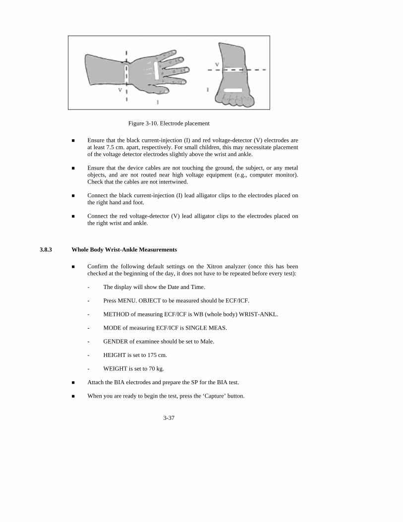
Figure 3-10. Electrode placement ! Ensure that the black current-injection (I) and red voltage-detector (V) electrodes are
at least 7.5 cm. apart, respectively. For small children, this may necessitate placement of the voltage detector electrodes slightly above the wrist and ankle.
! Ensure that the device cables are not touching the ground, the subject, or any metal objects, and are not routed near high voltage equipment (e.g., computer monitor). Check that the cables are not intertwined.
! Connect the black current-injection (I) lead alligator clips to the electrodes placed on the right hand and foot.
! Connect the red voltage-detector (V) lead alligator clips to the electrodes placed on the right wrist and ankle.
3.8.3 Whole Body Wrist-Ankle Measurements
! Confirm the following default settings on the Xitron analyzer (once this has been checked at the beginning of the day, it does not have to be repeated before every test):
- The display will show the Date and Time.
- Press MENU. OBJECT to be measured should be ECF/ICF.
- METHOD of measuring ECF/ICF is WB (whole body) WRIST-ANKL.
- MODE of measuring ECF/ICF is SINGLE MEAS.
- GENDER of examinee should be set to Male.
- HEIGHT is set to 175 cm.
- WEIGHT is set to 70 kg.
! Attach the BIA electrodes and prepare the SP for the BIA test.
! When you are ready to begin the test, press the ‘Capture’ button.
3-37

! The Xitron analyzer will begin the test.
! The system will monitor the progress of the analyzer and data capture.
! When the test begins, the system will check the ‘Performing Test’ button.
! The system will check the ‘Performing Test’ button and the ‘Capturing Data’ button. At this point, you can remove the electrodes and help the SP off the table. See Figure 3-11.
! When the data are captured the system will check the ‘Data Captured’ button.
Figure 3-11. BIA data capture
! A ‘Status’ bar will also monitor the progress of the data capture.
! Remove the electrodes and help the SP get off the table if necessary.
3-38

3.9 DXA Scan Data
! Analysis of the scans will be done at the QC Reading Center.
! Figures 3-12 and 3-13 show the data displayed after the regions of interest are selected and the analysis is completed.
Figure 3-12. Data displayed after analysis (1)
! Figure 3-12 displays the percent fat by region and for the total body. The percent total
body fat for the hypothetical SP in the example is 23.6 percent.
! Figure 3-13 displays the bone mineral density (BMD) for the SP. In addition, the box below the graph gives the T-score and the Z-score for the BMD for this SP.
3-39
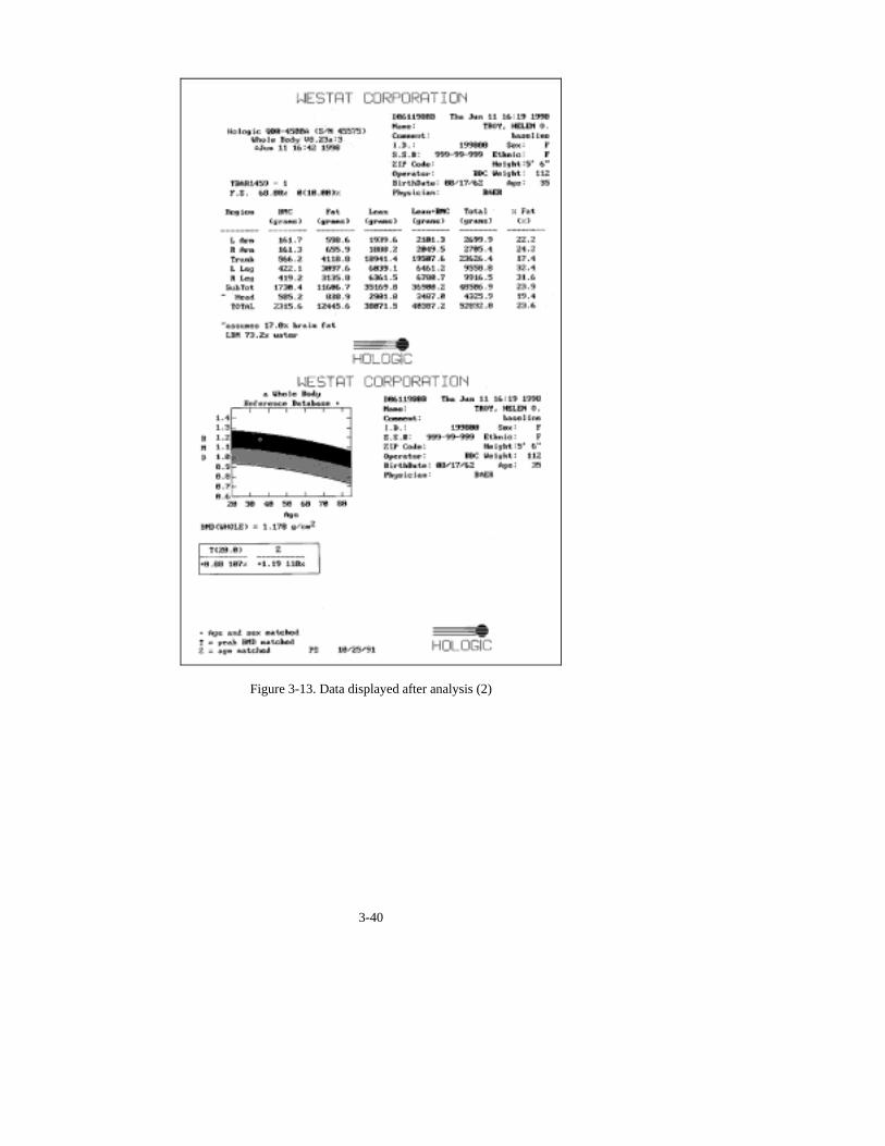
Figure 3-13. Data displayed after analysis (2)
3-40

4. DATA ENTRY SCREENS
4.1 Shared Exclusion Questions
Figure 4-1. Shared exclusion questions (1)
! The Shared Exclusion Questions will be answered in the Household Interview and
will be disabled. These responses cannot be changed in the MEC.
! If the Shared Exclusion Questions have not been answered in the Household Interview, they will be enabled and will be answered in the MEC. See Figure 4-1. These questions will be answered one time only in the MEC in the first exam where Shared Exclusions are asked.
! Some exams do not require all the shared exclusions. In this situation, there may be some questions answered in one exam and then disabled in the remaining exams.
! It is possible to have some Shared Exclusion Questions answered and disabled and others not answered and enabled. (Example: If the Shared Exclusion Questions are not answered in the Household Interview and the SP goes to Muscle Strength before Body Composition, the questions on amputation would be answered and disabled from Muscle Strength but the question on weight will remain unanswered and enabled.)
4-41
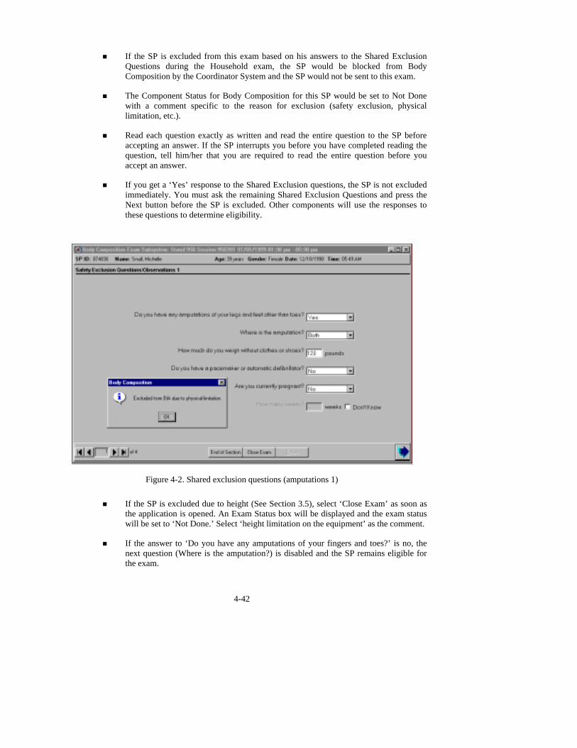
! If the SP is excluded from this exam based on his answers to the Shared Exclusion Questions during the Household exam, the SP would be blocked from Body Composition by the Coordinator System and the SP would not be sent to this exam.
! The Component Status for Body Composition for this SP would be set to Not Done with a comment specific to the reason for exclusion (safety exclusion, physical limitation, etc.).
! Read each question exactly as written and read the entire question to the SP before accepting an answer. If the SP interrupts you before you have completed reading the question, tell him/her that you are required to read the entire question before you accept an answer.
! If you get a ‘Yes’ response to the Shared Exclusion questions, the SP is not excluded immediately. You must ask the remaining Shared Exclusion Questions and press the Next button before the SP is excluded. Other components will use the responses to these questions to determine eligibility.
Figure 4-2. Shared exclusion questions (amputations 1) ! If the SP is excluded due to height (See Section 3.5), select ‘Close Exam’ as soon as
the application is opened. An Exam Status box will be displayed and the exam status will be set to ‘Not Done.’ Select ‘height limitation on the equipment’ as the comment.
! If the answer to ‘Do you have any amputations of your fingers and toes?’ is no, the next question (Where is the amputation?) is disabled and the SP remains eligible for the exam.
4-42
! The question ‘Where is the amputation?’ has response options of Right, Left, or Both; this question is enabled when you enter ‘Yes’ to the previous question.
! If the response to ‘Do you have any amputations of your legs and feet other than toes?’ is ‘Yes’ and the response to the question on location of the amputation is ‘Right,’ ‘Left,’ or ‘Both,’ the system will go to the remaining questions.
! If the location of the amputation is not selected (Right, Left, or Both), the system will display a message ‘You must indicate where the amputation is.’ Click OK and enter the location of the amputation.
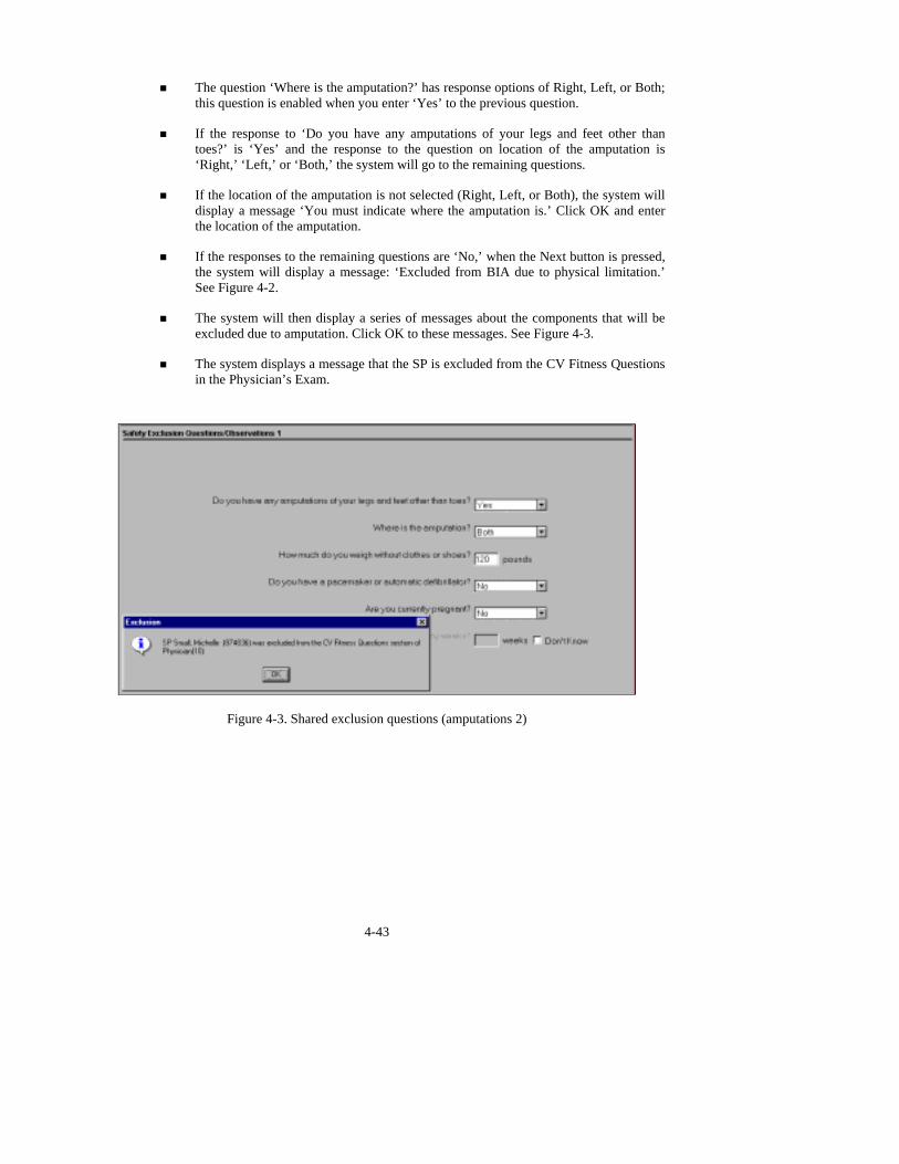
! If the responses to the remaining questions are ‘No,’ when the Next button is pressed, the system will display a message: ‘Excluded from BIA due to physical limitation.’ See Figure 4-2.
! The system will then display a series of messages about the components that will be excluded due to amputation. Click OK to these messages. See Figure 4-3.
! The system displays a message that the SP is excluded from the CV Fitness Questions in the Physician’s Exam.
Figure 4-3. Shared exclusion questions (amputations 2)
4-43
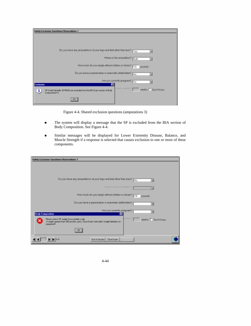
Figure 4-4. Shared exclusion questions (amputations 3)
! The system will display a message that the SP is excluded from the BIA section of
Body Composition. See Figure 4-4.
! Similar messages will be displayed for Lower Extremity Disease, Balance, and Muscle Strength if a response is selected that causes exclusion to one or more of these components.
4-44
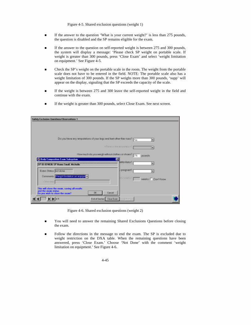
Figure 4-5. Shared exclusion questions (weight 1)
! If the answer to the question ‘What is your current weight?’ is less than 275 pounds,
the question is disabled and the SP remains eligible for the exam.
! If the answer to the question on self-reported weight is between 275 and 300 pounds, the system will display a message: ‘Please check SP weight on portable scale. If weight is greater than 300 pounds, press ‘Close Exam’ and select ‘weight limitation on equipment.’ See Figure 4-5.
! Check the SP’s weight on the portable scale in the room. The weight from the portable scale does not have to be entered in the field. NOTE: The portable scale also has a weight limitation of 300 pounds. If the SP weighs more than 300 pounds, ‘supp’ will appear on the display, signaling that the SP exceeds the capacity of the scale.
! If the weight is between 275 and 300 leave the self-reported weight in the field and continue with the exam.
! If the weight is greater than 300 pounds, select Close Exam. See next screen.
Figure 4-6. Shared exclusion questions (weight 2)
! You will need to answer the remaining Shared Exclusions Questions before closing
the exam.
! Follow the directions in the message to end the exam. The SP is excluded due to weight restriction on the DXA table. When the remaining questions have been answered, press ‘Close Exam.’ Choose ‘Not Done’ with the comment ‘weight limitation on equipment.’ See Figure 4-6.
4-45
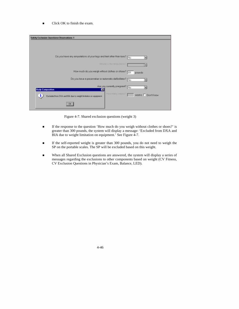
! Click OK to finish the exam.
Figure 4-7. Shared exclusion questions (weight 3)
! If the response to the question ‘How much do you weigh without clothes or shoes?’ is
greater than 300 pounds, the system will display a message: ‘Excluded from DXA and BIA due to weight limitation on equipment.’ See Figure 4-7.
! If the self-reported weight is greater than 300 pounds, you do not need to weigh the SP on the portable scales. The SP will be excluded based on this weight.
! When all Shared Exclusion questions are answered, the system will display a series of messages regarding the exclusions to other components based on weight (CV Fitness, CV Exclusion Questions in Physician’s Exam, Balance, LED).
4-46

Figure 4-8. Shared exclusion questions (pacemaker or automatic defibrillator)
! If the response to the question ‘Do you have a pacemaker or automatic defibrillator?’
is ‘Yes,’ the system will display a message: ‘Excluded from BIA for safety reasons.’ (This message will be displayed after all Shared Exclusion Questions have been answered and the Next button is pressed). See Figure 4-8.
! Click OK to this message.
! A series of exclusion messages will be given to indicate that the SP is also excluded from the Periodontal section of the Dental Exam, the CV Fitness Exam, and the CV Fitness Exclusion questions in the Physician’s Exam.
! Click OK to these messages.
! The Component Status will be set to ‘Not Done’ with the comment ‘safety exclusion.’
4-47

Figure 4-9. Shared exclusion questions (pregnancy 1) ! If the response to the question ‘Are you currently pregnant?’ is ‘Yes,’ the SP will be
excluded from BIA and DXA due to pregnancy status.
! The system will go to the next question to determine how many weeks pregnant.
! When the next button is pressed, a message will be displayed: ‘Excluded from DXA and BIA due to pregnancy status.’ Press OK to this message. See Figure 4-9.
! A series of messages will be displayed to indicate exclusion to other components (CV Fitness questions in the Physician’s Exam and CV Fitness if weeks pregnant is greater than 12 weeks).
! Click OK to these messages.
! The Component Status will be set to ‘Not done’ with the comment ‘SP pregnant.’
4-48
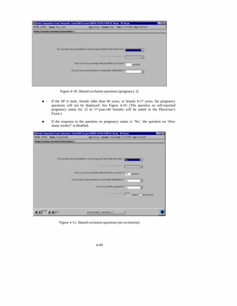
Figure 4-10. Shared exclusion questions (pregnancy 2) ! If the SP is male, female older than 60 years, or female 8-17 years, the pregnancy
questions will not be displayed. See Figure 4-10. (The question on self-reported pregnancy status for 12 to 17-year-old females will be asked in the Physician’s Exam.)
! If the response to the question on pregnancy status is ‘No,’ the question on ‘How many weeks?’ is disabled.
4-49
Figure 4-11. Shared exclusion questions (no exclusions)
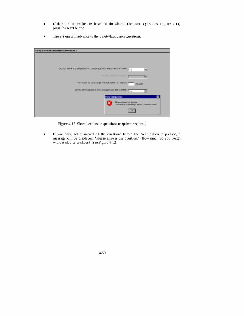
! If there are no exclusions based on the Shared Exclusion Questions, (Figure 4-11) press the Next button.
! The system will advance to the Safety/Exclusion Questions.
Figure 4-12. Shared exclusion questions (required response)
! If you have not answered all the questions before the Next button is pressed, a
message will be displayed: ‘Please answer the question.’ ‘How much do you weigh without clothes or shoes?’ See Figure 4-12.
4-50

4.2 Safety/Exclusion Questions
Figure 4-13. Safety/exclusion questions (1) ! The Safety/Exclusion Questions should be read exactly as written. Read the entire
question before accepting an answer. If the SP interrupts you before you have completed reading the question, say that you are required to read the entire question before accepting an answer. See Figure 4-13.
! All Safety/Exclusion questions must be answered. Some questions exclude the SP from BIA, other questions exclude from DXA.
4-51

Figure 4-14. Safety/exclusion questions (2)
! See Figure 4-14 for responses to the question ‘Has SP removed all jewelry,
eyeglasses, hair ornaments, and other objects from the hair and body?’ Interpret the responses as follows:
- Yes – The SP has removed all jewelry and objects that might interfere with the scan.
- No, exclude – The SP is unable or unwilling to remove jewelry and objects that might affect the data to a large degree.
- No, OK to continue – The SP has not removed all jewelry or other things but the objects are small. Continue with the scan and make a comment about this.
- Don’t Know – The technician and/or the SP does not know if everything has been removed. This situation should not occur frequently.
4-52
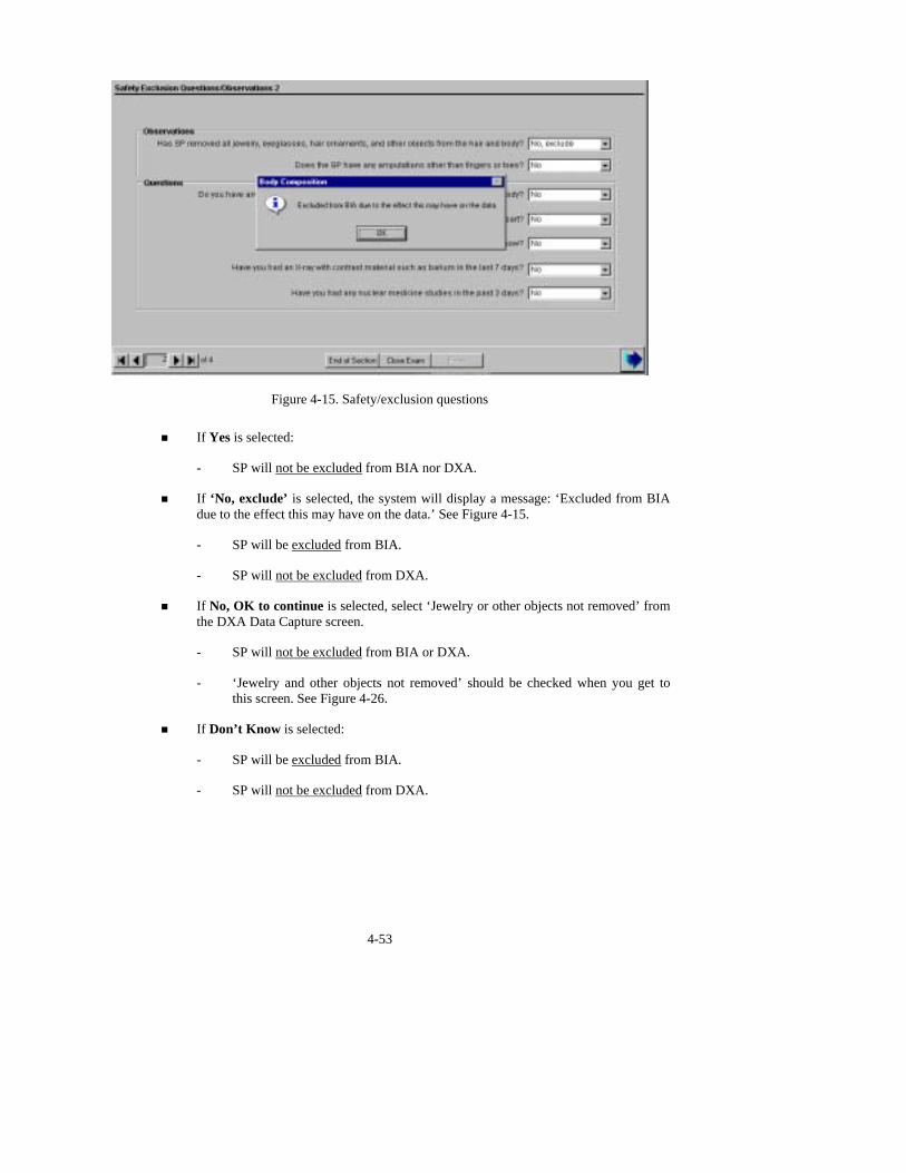
Figure 4-15. Safety/exclusion questions
! If Yes is selected:
- SP will not be excluded from BIA nor DXA.
! If ‘No, exclude’ is selected, the system will display a message: ‘Excluded from BIA due to the effect this may have on the data.’ See Figure 4-15.
- SP will be excluded from BIA.
- SP will not be excluded from DXA.
! If No, OK to continue is selected, select ‘Jewelry or other objects not removed’ from the DXA Data Capture screen.
- SP will not be excluded from BIA or DXA.
- ‘Jewelry and other objects not removed’ should be checked when you get to this screen. See Figure 4-26.
! If Don’t Know is selected:
- SP will be excluded from BIA.
- SP will not be excluded from DXA.
4-53

Figure 4-16. Safety/exclusion questions (amputations) ! If the response to the question ‘ Does the SP have any amputations other than fingers
or toes?’ is No, continue with the questions.
! If the response is yes, the SP will be excluded from BIA but not DXA. See Figure 4-16.
! Continue with the remaining questions. When the Next button is pressed, a message will be displayed: ‘Excluded from BIA due to physical limitation.’ See Figure 4-16.
! The Component Status for BIA will be set to Not Done with the comment physical limitation.
! The system will go to the DXA screen.
4-54

Figure 4-17. Safety/exclusion questions (artificial joints)
! If the response to the question ‘Do you have any artificial joints, pins, plates, or other
types of metal objects in your body?’ is No, continue with the questions.
! If the response is yes, the SP will be excluded from BIA but not DXA.
! Continue with the remaining questions. When the Next button is pressed, a message will be displayed: ‘Excluded from BIA for safety reasons.’ Click OK to this message. See Figure 4-17.
! The Component Status for BIA will be set to Not Done with the comment ‘safety reasons.’
! The system will go to the DXA screen.
4-55
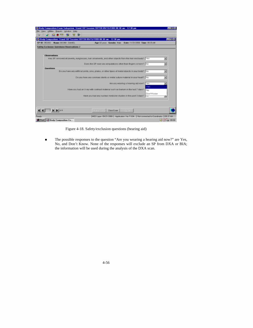
Figure 4-18. Safety/exclusion questions (hearing aid)
! The possible responses to the question “Are you wearing a hearing aid now?” are Yes,
No, and Don’t Know. None of the responses will exclude an SP from DXA or BIA; the information will be used during the analysis of the DXA scan.
4-56

Figure 4-19. Safety/exclusion questions (coronary stents)
! If the response to the question ‘Do you have any coronary stents or metal sutures in
your heart?’ is No, continue with the remaining questions.
! If the response to the question is Yes, the SP will be excluded from BIA but not DXA.
! Continue with the remaining questions. When the Next button is pressed, a message will be displayed: ‘Excluded from BIA for safety reasons.’ Click OK to this message. See Figure 4-18.
! The BIA Component Status will be set to Not Done with the comment ‘safety exclusion.’
! The system will go to the DXA screen.
4-57

Figure 4-20. Safety/exclusion questions (contrast radiography)
! If the response to the question ‘Have you had an X-ray with contrast material such as
barium in the last 7 days?’ is No, continue with the next questions.
! If the response to the question is Yes, the SP will be excluded from DXA but not BIA.
! Complete the remainder of the questions. When the next button is pressed, a message will be displayed: ‘Excluded from DXA due to the effect contrast material may have on the data.’ Click OK to this message.
! The DXA Component Status will be set to Not Done with the comment ‘data effect.’
! The system will go to the BIA screen.
4-58

Figure 4-21. Safety/exclusion questions (nuclear medicine studies)
! If the response to the question ‘Have you had any nuclear medicine studies in the past
3 days?’ is No, continue with the next questions.
! If the response to the question is Yes, the SP will be excluded from DXA but not BIA.
! Complete the remainder of the questions. When the next button is pressed, a message will be displayed: ‘Excluded from DXA due to the effect radionuclides may have on the data.’ Click OK to this message. See Figure 4-21.
! The DXA Component Status will be set to Not Done with the comment ‘data effect.’
! The system will go to the BIA screen.
4-59

Figure 4-22. Safety/exclusion questions (required entry)
! If the Next button is pressed before all the questions are answered, a message will be
displayed reminding you to answer the question. See Figure 4-22.
! Click OK to this message and ask the missed question.
Figure 4-23. Safety/exclusion questions (don’t know)
! If the response to any of the questions is Don’t Know, the SP will be excluded from
one or both components depending on the exclusion question. Click OK to this message and continue to the next screen. See Figure 4-23.
4-60
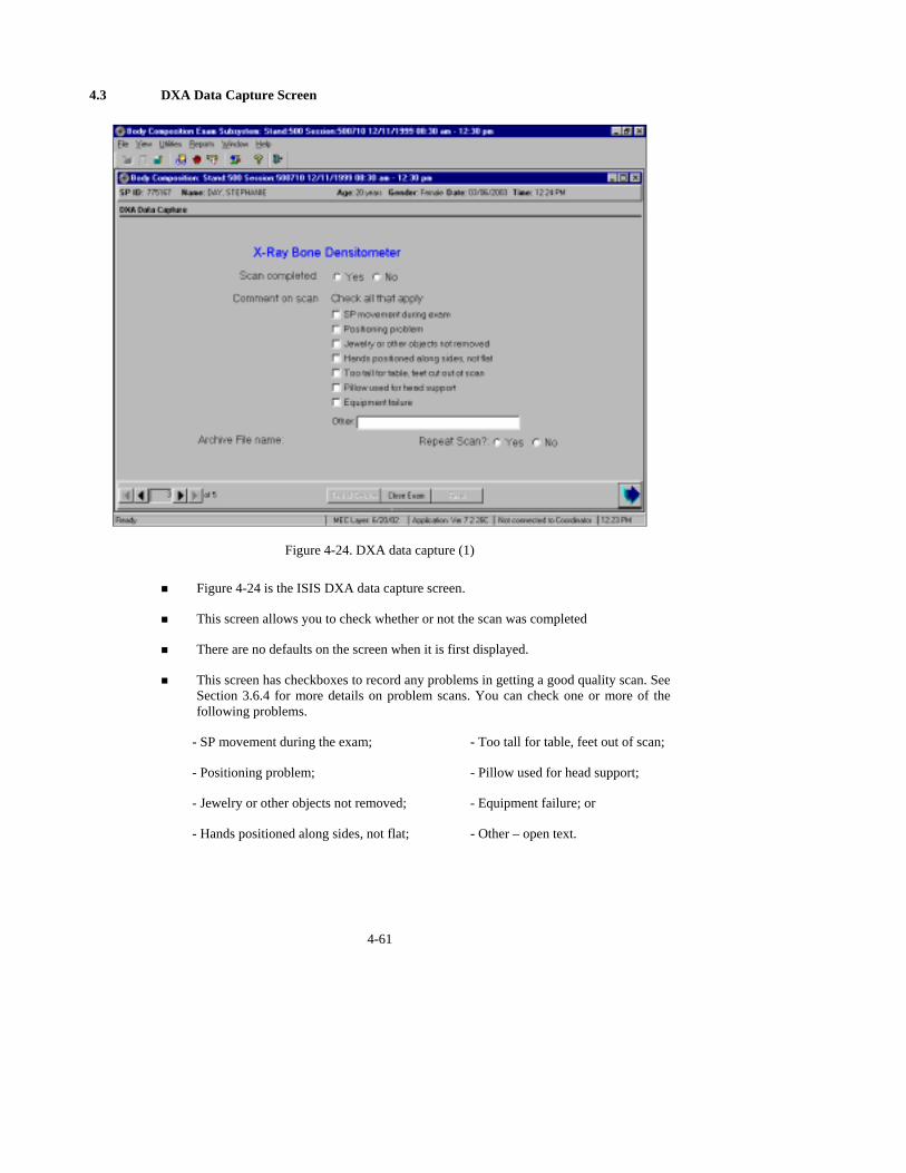
4.3 DXA Data Capture Screen
Figure 4-24. DXA data capture (1)
! Figure 4-24 is the ISIS DXA data capture screen.
! This screen allows you to check whether or not the scan was completed
! There are no defaults on the screen when it is first displayed.
! This screen has checkboxes to record any problems in getting a good quality scan. See Section 3.6.4 for more details on problem scans. You can check one or more of the following problems.
- SP movement during the exam; - Too tall for table, feet out of scan;
- Positioning problem; - Pillow used for head support;
- Jewelry or other objects not removed; - Equipment failure; or
- Hands positioned along sides, not flat; - Other – open text.
4-61
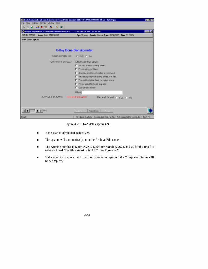
Figure 4-25. DXA data capture (2)
! If the scan is completed, select Yes.
! The system will automatically enter the Archive File name.
! The Archive number is D for DXA, 030603 for March 6, 2003, and 00 for the first file to be archived. The file extension is .ARC. See Figure 4-25.
! If the scan is completed and does not have to be repeated, the Component Status will be ‘Complete.’
4-62

Figure 4-26. DXA data capture (comments on scan)
! During and immediately after the scan, check the scan for quality.
! If one or more of the Comments on scan apply, check all that apply.
! If the quality of the scan is not adequate and you can correct the problem, you can repeat the scan if the SP is in agreement. See Section 3.6.4.
! Check Yes or No to indicate if the DXA scan needs to be repeated.
4-63
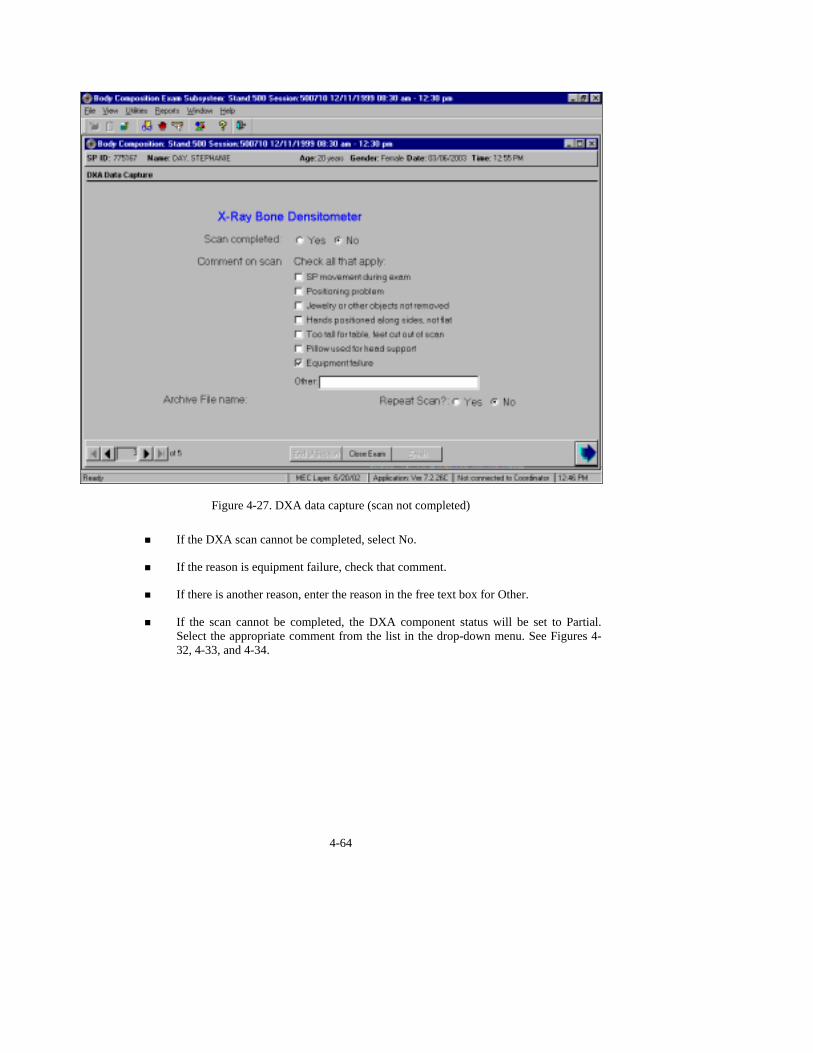
Figure 4-27. DXA data capture (scan not completed)
! If the DXA scan cannot be completed, select No.
! If the reason is equipment failure, check that comment.
! If there is another reason, enter the reason in the free text box for Other.
! If the scan cannot be completed, the DXA component status will be set to Partial. Select the appropriate comment from the list in the drop-down menu. See Figures 4-32, 4-33, and 4-34.
4-64

4.3.1 Getting Permission to Repeat a DXA Scan
Figure 4-28. DXA data capture (consent for second scan)
! If a repeat scan is necessary, you must get permission from the SP.
! Read the Standard Script for obtaining consent for a second scan to the SP.
! If the SP agrees to the second scan, check yes.
! Repeat the scan using the procedures outlined for the first scan.
! Before starting the second scan, make sure all corrections have been made. If a problem occurs with this scan, you will not be able to repeat the exam on this SP again.
4-65
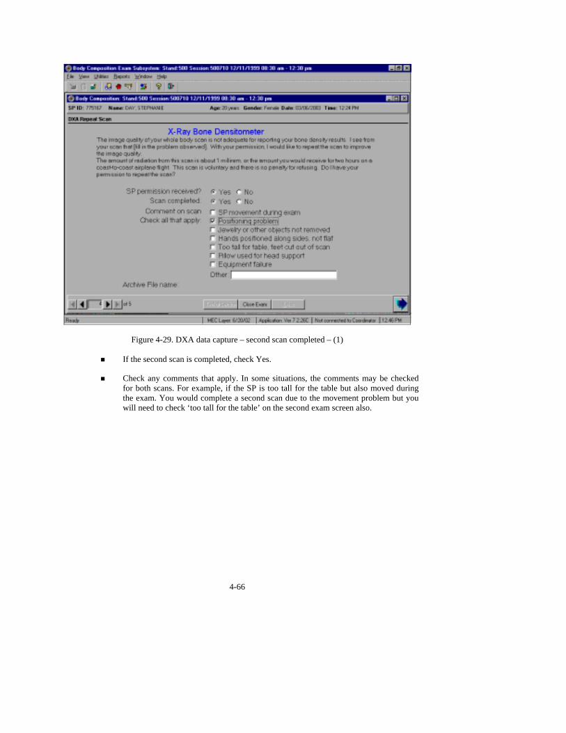
Figure 4-29. DXA data capture – second scan completed – (1)
! If the second scan is completed, check Yes.
! Check any comments that apply. In some situations, the comments may be checked for both scans. For example, if the SP is too tall for the table but also moved during the exam. You would complete a second scan due to the movement problem but you will need to check ‘too tall for the table’ on the second exam screen also.
4-66
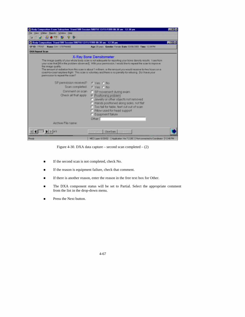
Figure 4-30. DXA data capture – second scan completed – (2)
! If the second scan is not completed, check No.
! If the reason is equipment failure, check that comment.
! If there is another reason, enter the reason in the free text box for Other.
! The DXA component status will be set to Partial. Select the appropriate comment from the list in the drop-down menu.
! Press the Next button.
4-67
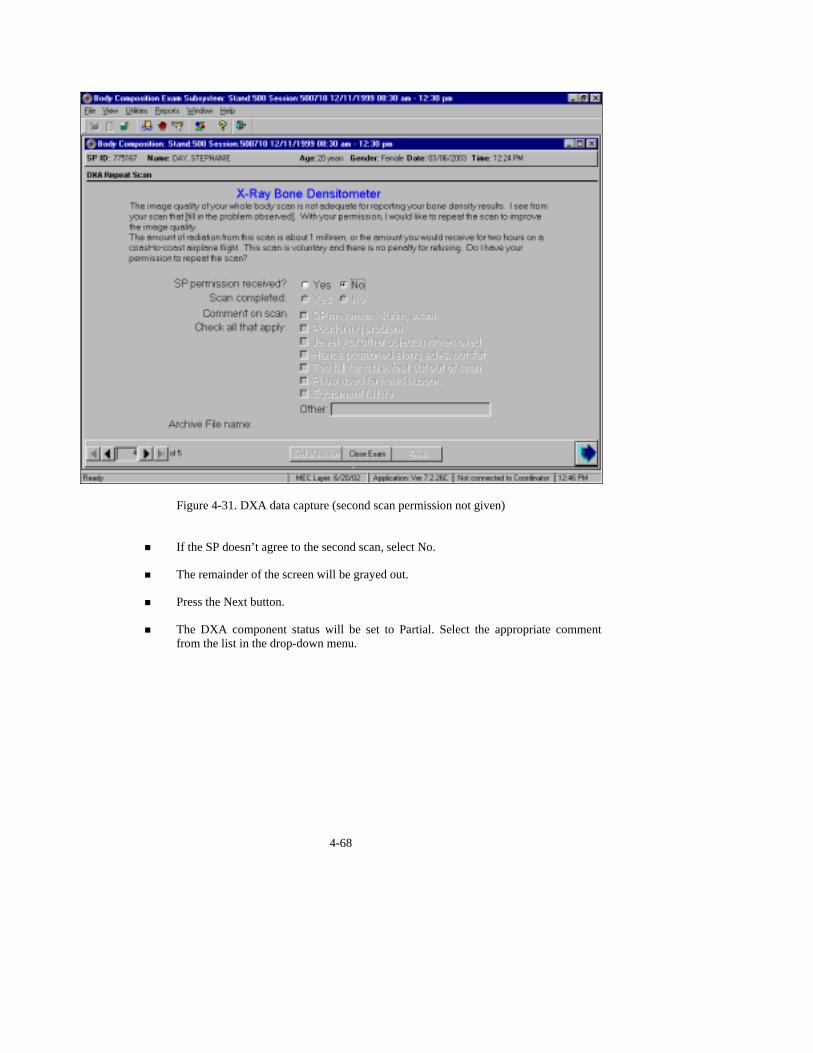
Figure 4-31. DXA data capture (second scan permission not given)
! If the SP doesn’t agree to the second scan, select No.
! The remainder of the screen will be grayed out.
! Press the Next button.
! The DXA component status will be set to Partial. Select the appropriate comment from the list in the drop-down menu.
4-68

4.4 DXA Component Status
Figure 4-32. DXA component status (1)
! If the component status is ‘Partial’ or ‘Not Done,’ the system will require a comment
to be selected from the drop-down menu. See Figure 4-32.
! The comments in the drop-down box are:
- Safety exclusion;
- SP refusal;
- No time;
- Physical limitation;
- Communication problem; and
- Equipment failure.
4-69

Figure 4-33. DXA component status (2)
! Other comments in the drop-down box are shown in Figure 4-33:
- SP ill/emergency;
- Data effect;
- Inability to lie still;
- Interrupted;
- Pain or discomfort; and
- SP moved during procedure.
4-70
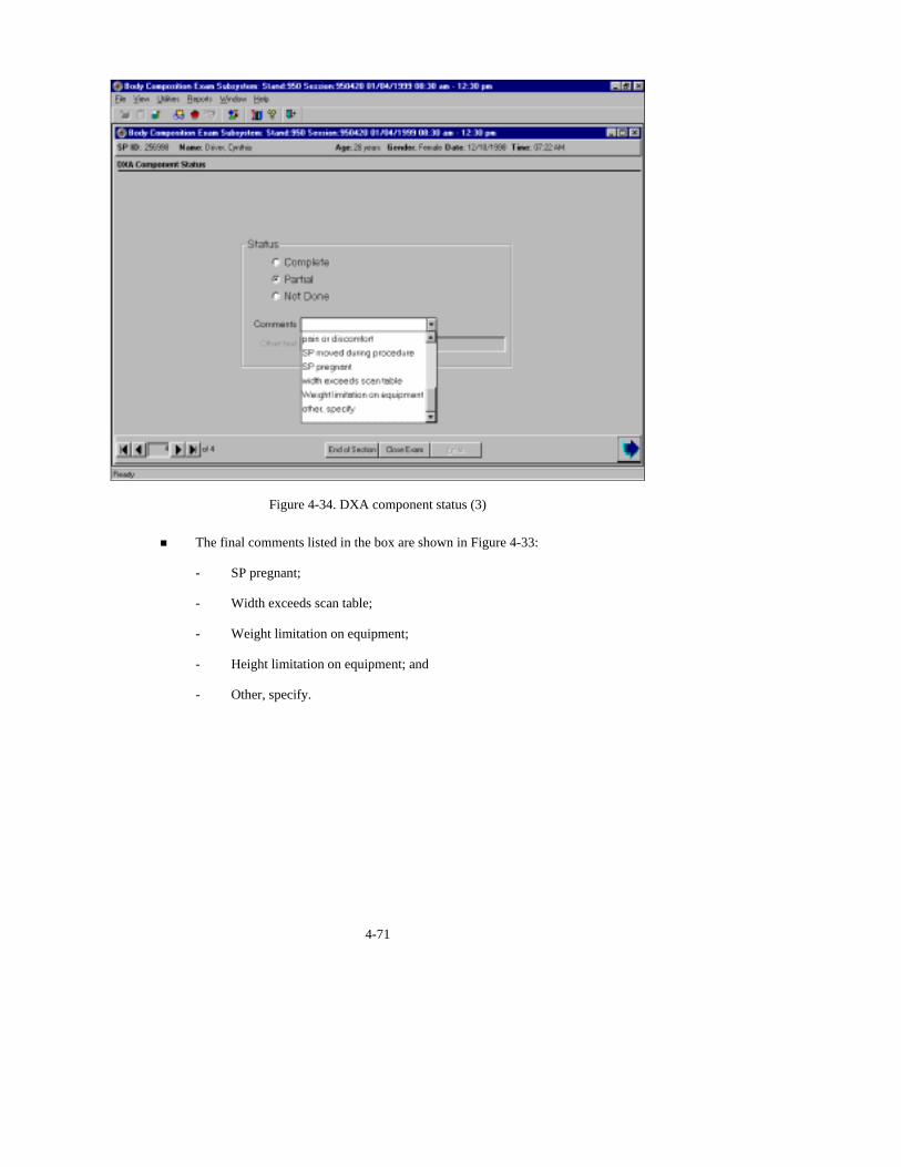
Figure 4-34. DXA component status (3)
! The final comments listed in the box are shown in Figure 4-33:
- SP pregnant;
- Width exceeds scan table;
- Weight limitation on equipment;
- Height limitation on equipment; and
- Other, specify.
4-71

Figure 4-35. DXA component status (required comments)
! If a comment is not selected when the status is ‘Partial’ or ‘Not Done,’ a message will
be displayed: ‘Please select comments.’ See Figure 4-34.
! Click OK to this message and select the appropriate comment.
! Press the Finish button to end the exam.
4.5 BIA Data Capture
4-72

Figure 4-36. BIA data capture (1)
! The BIA data capture screen is shown in Figure 4-35.
! Attach BIA electrodes and prepare the SP for the BIA test.
! When you are ready to begin the test, check ‘Electrodes attached.’
! Then press ‘Capture.’
! The Xitron analyzer will begin the test.
Figure 4-37. BIA data capture (2)
! The system will monitor the progress of the analyzer and data capture.
! When the test begins, the system will check the ‘Performing test’ button.
! This will take approximately 5 seconds.
! When the test is completed, the system will check the ‘Capturing data’ button. See Figure 4-36.
! At this time you may remove the leads and electrodes as this will not interfere with the data capture.
! The progress bar will show the progress of the data as it is captured.
4-73

Figure 4-38. BIA data capture (3)
! When all the data have been captured, the system will check the ‘Data Captured’
button. See Figure 4-37.
! The progress bar will be full.
! Press the Next button to advance to the BIA Component status screen.
4-74

4.6 BIA Component Status
Figure 4-39. BIA component status (1)
! If the Component Status for BIA is ‘Partial’ or ‘Not Done’ a comment is required.
! In many situations, this comment is defaulted by the system to the appropriate comment.
! If the comment is not defaulted, you must select the appropriate comment.
! The comments in the drop-down menu are shown in Figure 4-38:
- Safety exclusion;
- SP refusal;
- No time;
- Physical limitation;
- Communication problem; and
- Equipment failure.
4-75

Figure 4-40. BIA component status (2)
! Additional comments from the list are shown in Figure 4-39:
- SP ill/emergency;
- Data effect;
- Interrupted;
- SP pregnant;
- Weight limitation on equipment;
- Height limitation on equipment; and
- Other, specify.
4-76
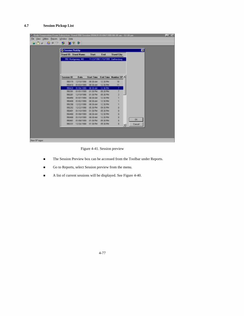
4.7 Session Pickup List
Figure 4-41. Session preview
! The Session Preview box can be accessed from the Toolbar under Reports.
! Go to Reports, select Session preview from the menu.
! A list of current sessions will be displayed. See Figure 4-40.
4-77
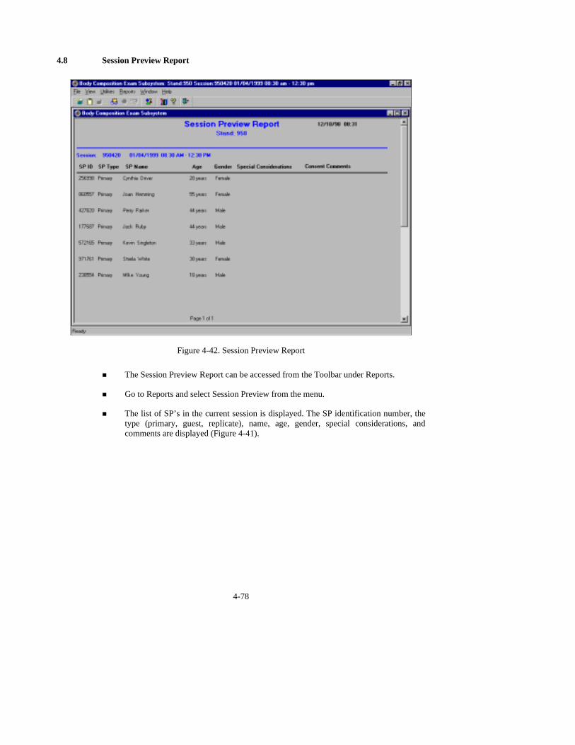
4.8 Session Preview Report
Figure 4-42. Session Preview Report
! The Session Preview Report can be accessed from the Toolbar under Reports.
! Go to Reports and select Session Preview from the menu.
! The list of SP’s in the current session is displayed. The SP identification number, the type (primary, guest, replicate), name, age, gender, special considerations, and comments are displayed (Figure 4-41).
4-78

4.9 Room Log
Figure 4-43. Room log for body composition
! The Room Log can be accessed from the Toolbar under Reports.
! Go to Reports and select Room Log from the menu.
! A list of the SP’s eligible for this component is displayed.
! The SP ID, name, sex, age, SP status, and component status are displayed. See Figure 4-42.
4-79
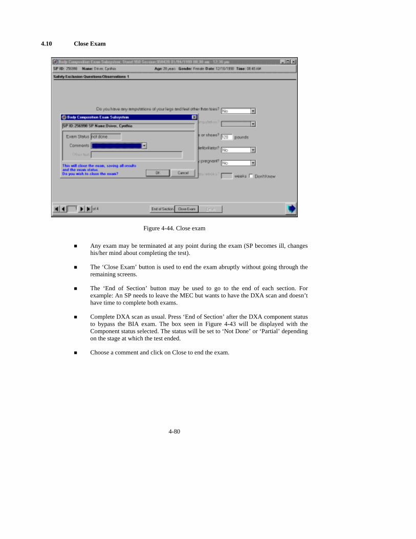
4.10 Close Exam
Figure 4-44. Close exam
! Any exam may be terminated at any point during the exam (SP becomes ill, changes
his/her mind about completing the test).
! The ‘Close Exam’ button is used to end the exam abruptly without going through the remaining screens.
! The ‘End of Section’ button may be used to go to the end of each section. For example: An SP needs to leave the MEC but wants to have the DXA scan and doesn’t have time to complete both exams.
! Complete DXA scan as usual. Press ‘End of Section’ after the DXA component status to bypass the BIA exam. The box seen in Figure 4-43 will be displayed with the Component status selected. The status will be set to ‘Not Done’ or ‘Partial’ depending on the stage at which the test ended.
! Choose a comment and click on Close to end the exam.
4-80
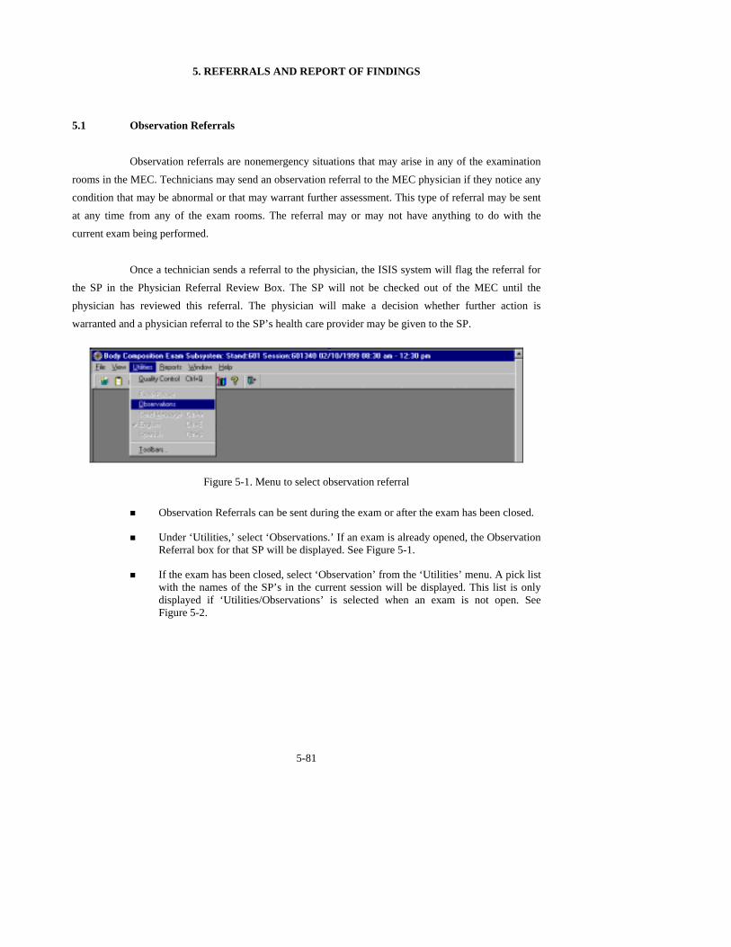
5. REFERRALS AND REPORT OF FINDINGS
5.1 Observation Referrals
Observation referrals are nonemergency situations that may arise in any of the examination
rooms in the MEC. Technicians may send an observation referral to the MEC physician if they notice any condition that may be abnormal or that may warrant further assessment. This type of referral may be sent at any time from any of the exam rooms. The referral may or may not have anything to do with the current exam being performed.
Once a technician sends a referral to the physician, the ISIS system will flag the referral for
the SP in the Physician Referral Review Box. The SP will not be checked out of the MEC until the physician has reviewed this referral. The physician will make a decision whether further action is
warranted and a physician referral to the SP’s health care provider may be given to the SP.
Figure 5-1. Menu to select observation referral
! Observation Referrals can be sent during the exam or after the exam has been closed.
! Under ‘Utilities,’ select ‘Observations.’ If an exam is already opened, the Observation Referral box for that SP will be displayed. See Figure 5-1.
! If the exam has been closed, select ‘Observation’ from the ‘Utilities’ menu. A pick list with the names of the SP’s in the current session will be displayed. This list is only displayed if ‘Utilities/Observations’ is selected when an exam is not open. See Figure 5-2.
5-81

Figure 5-2. Pick list of SPs in current session
! Select the name of the SP for whom an observation referral should be sent. Click OK.
Figure 5-3. Observation referral in body composition
! Type in the message you would like to send to the physician. When you are finished,
click OK. See Figure 5-3.
5-82

Figure 5-4. Observation referral from other components in physician’s referral review box
! Figure 5-4 shows the referral as it appears in the Physician’s Referral Review box.
The message typed in the Observation Referral box in Body Composition appears in this box in the Physician Referral Review.
! The physician will review this referral and make a decision about further action if warranted.
! The SP cannot be checked out of the MEC until the physician has reviewed this referral.
5.2 Report of Findings for Body Composition
Each SP will be given a report of the results or findings for the exams performed. There will be no Report of Findings on the BIA results. The Report of Findings for the DXA Exam will include a report on the total bone mineral density (BMD), the T- score for the BMD, and the percent total body fat. The heading for the report will be ‘Whole Body Scan.’
Results will be included in the final report of findings sent from NCHS. BMD results will
not be reported to participants under 20 years of age because the reference group used for analyzing the BMD does not include persons under 20 years.
The variables reported will be total BMD and interpretation using the T-score from analyzed
whole body scan, and percent of total body fat. Males will be analyzed as if they were females because the reference group includes only females.
5-83

5-84
5.2.1 General Statement for Report of Findings for Body Composition
The whole body DXA scan provides two pieces of health information—the first is your body
composition and the second is your bone mineral density.
5.2.2 Report of Findings Statement for Total Body Fat
The body composition analysis showed that your total body fat is ____%
Statement Total Body Fat for Males Age <17 Years
The percentage of body fat varies considerably among normal people. For boys between the ages of 6 and 16, percent body fat normally ranges from about 5 percent to 26 percent.
Statement for Total Body Fat for All Others (Except Boys <17 Years)
The percentage of body fat varies considerably among normal people. For adults, the percentages reach up to 30 percent for men and 35 percent for women in middle age.
5.2.3 Report of Findings Statement for Total Bone Density
Statement for Total Bone Density if SP is < 20 Years of Age
This is the first time that bone density in young people is being measured in a national survey. We are using this information to learn about bone formation in your age group. We will not be able to give you results about your bone density until we know what normal is. Your participation is helping us determine this.
5-85
Statement for Total Bone Density if SP is >/= 20 Years of Age
The bone density measurement can help identify persons who may be at greater risk for fracture because they have weaker bones. In general, a lower bone density means that the bone is weaker.
However, not all men or women with low bone density will have fractures.
5.2.4 Report of Findings Statement for T-Score
Statement for T-Score if T-Score > 1.0
The results from your whole body scan show that your bone density is ______ g/cm2, and
your T-score is ____. Compared with young adults, your bone density is normal.
Statement if T-Score < 1.0 but > -2.5
The results from your whole body scan show that your bone density is ______ g/cm2, and your T-score is ____. Compared with young adults, your bone density is low.
The whole body scan is used for research only. This type of scan gives information on the bone density of your skeleton. The fragility of your spine or hip are best evaluated by DXA scans of those specific areas.
Statement for T-Score if T-Score < -2.5
The results from your whole body scan show that your bone density is ______ g/cm2, and
your T-score is ____. Compared with young adults, your bone density is very low. Most people develop low bone density over many years and you should not be alarmed. We
do recommend that you discuss these results with your doctor in the near future. Your doctor may wish to
do another bone density test of your spine or hip, since fractures due to osteoporosis often occur at these sites.

5.2.5 Report of Findings Statement if SP Was Excluded for Safety Reasons
“This component was not completed.”
5.2.6 Sample Preliminary Report of Findings
Refer to Figures 5-5 and 5-6 for samples of preliminary reports of findings.
Figure 5-5. Sample Preliminary Report of Findings for all SPs > 20 years of age
5-86

Figure 5-6. Sample Preliminary Report of Findings for male SPs < 17 years of age
5-87

6-88
6. QUALITY CONTROL
6.1 Equipment and Room Set-Up Checks
The equipment, room supplies, and room set-up need to be checked on a regular basis. Some
checks are completed daily and others need only be completed on a weekly basis or at the beginning of each stand. These checks include calibration checks, maintenance inspection of equipment and supplies, and preparation of the room and equipment for the session exams.
Each time you log onto the application, the system will remind you to do quality control (QC) checks if the checks have not been completed for that time period. The checks are to be completed daily, weekly, 3 times a week, and/or every stand. If you do not have time to do the checks when you log on, you can bypass this message and complete the checks at a later time. However, this message will be
displayed each time you log on until you have completed the checks for that time period. Once you have completed the checks and entered this in the system, the message box with the reminder will not be displayed again until the appropriate time period has passed.
An exception to the above is the QC check for the spine phantom. The spine phantom must be calibrated daily before the densitometer will allow scans to be completed. If an attempt is made to perform a scan before the daily QC is completed, an error message will be displayed. Press Enter at this message and complete the spine phantom calibration.
The daily, 3 times/week, weekly, and once-a-stand checks are listed in the following
sections.
6.1.1 Daily
! DXA – 1 spine phantom (Hologic Anthropomorphic Spine Phantom – HASP).
! DXA – Check that table scan area is clear of articles that might interfere with table movement.
! DXA – Check runner area of table to confirm the area is clear of articles that might interfere with table movement.
! DXA - Archive SP and QC scans after each session.
! BIA – Turn on Xitron to initiate self-check. (If already on, turn off, then turn on.)

6-89
! BIA – Check that Xitron measurement cable is looped over wall hook to prevent being caught in the C-arm movement.
6.1.2 Three Times Per Week (1st, 3rd, and 5th days of work week)
! Complete all daily checks.
- DXA – 1 Spine Phantom
! DXA – 1 Slim-line Whole Body Phantom.
6.1.3 Weekly
! Complete all daily checks.
- DXA – 1 Spine Phantom
! Complete the ‘3 times weekly’ scans
- DXA –1 Slim-line Whole Body Phantom.
! DXA – 1 air scan.
! DXA – 1 step phantom.
! BIA – Complete Xitron circuit testing with electronic verification module.
! BIA – Check Xitron measurement cables for cracks or kinks.
! BIA – Check that Xitron rear panel pins are straight and connecting properly.
! BIA – Check that the springs in the alligator clips are functioning and close tightly on the electrodes.
! BIA – Wipe alligator clips with alcohol pads to remove electrode gum.
! Scrape teeth of alligator clips with alcohol pads to remove tarnish or corrosion if present.
6.1.4 Start of Stand
! DXA – 1 Spine Phantom
! DXA – 1 step phantom.
! DXA – 1 air scan.

6-90
! DXA – Complete 5 Slim-line Whole Body Phantom scans.
! DXA – Complete 10 scans of the circulating spine phantom (HSP-Q-96).
! DXA – Complete 10 scans of the circulating block phantom (NH #1).
! DXA – Complete 5 Hologic Whole Body Phantom (HWBP) scans (WB Phantom #008).
! DXA – Check that the locking pins have been removed before attempting to complete any scans.
6.1.5 End of Stand
! Clean DXA table.
6.2 Procedures for Completing QC Scans
6.2.1 Hologic Anthropomorphic Spine Phantom (HASP)
! At the main ‘Selections’ menu (Figure 6-1), highlight QC and press ‘Enter’ (or type ‘Q’).
! At ‘QC Selections’ (Figure 6-2), highlight ‘Scan’ and press ‘Enter’ (or type ‘S’) to begin the Spine Phantom QC.
! Read the messages on the Hologic computer screen. (If the step phantom hasn’t been scanned in the past week, a message will be displayed stating that it should be scanned following the spine phantom scan.) See Figure 6-3.

Figure 6-1. Main selections menu
Figure 6-2. Spine phantom quality control
6-91
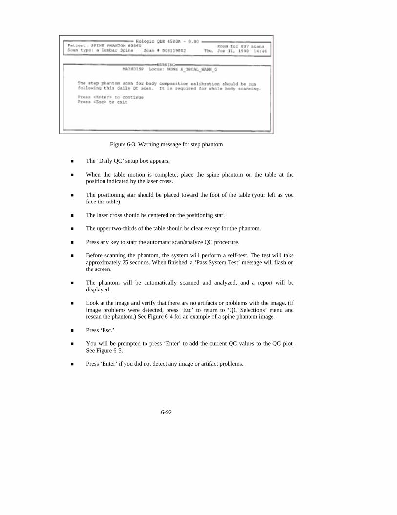
Figure 6-3. Warning message for step phantom ! The ‘Daily QC’ setup box appears.
! When the table motion is complete, place the spine phantom on the table at the position indicated by the laser cross.
! The positioning star should be placed toward the foot of the table (your left as you face the table).
! The laser cross should be centered on the positioning star.
! The upper two-thirds of the table should be clear except for the phantom.
! Press any key to start the automatic scan/analyze QC procedure.
! Before scanning the phantom, the system will perform a self-test. The test will take approximately 25 seconds. When finished, a ‘Pass System Test’ message will flash on the screen.
! The phantom will be automatically scanned and analyzed, and a report will be displayed.
! Look at the image and verify that there are no artifacts or problems with the image. (If image problems were detected, press ‘Esc’ to return to ‘QC Selections’ menu and rescan the phantom.) See Figure 6-4 for an example of a spine phantom image.
! Press ‘Esc.’
! You will be prompted to press ‘Enter’ to add the current QC values to the QC plot. See Figure 6-5.
! Press ‘Enter’ if you did not detect any image or artifact problems.
6-92

Figure 6-4. Spine phantom QC image
Figure 6-5. Spine phantom QC
6.2.1.1 Checking BMD
! When you press ‘Enter’ to add the current scan to the plot, the QC plot for BMD will appear.
! Check the BMD graph for the circle for today’s scan (at far right side of graph). See Figure 6-6.
! The circle should be within the two dotted lines.
! The CV for BMD should be at or below 0.60 percent.
6-93
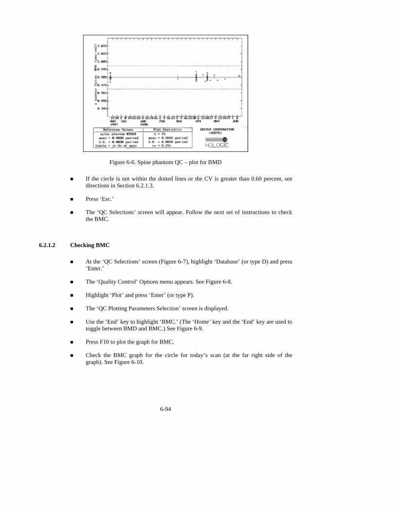
Figure 6-6. Spine phantom QC – plot for BMD ! If the circle is not within the dotted lines or the CV is greater than 0.60 percent, see
directions in Section 6.2.1.3.
! Press ‘Esc.’
! The ‘QC Selections’ screen will appear. Follow the next set of instructions to check the BMC.
6.2.1.2 Checking BMC
! At the ‘QC Selections’ screen (Figure 6-7), highlight ‘Database’ (or type D) and press ‘Enter.’
! The ‘Quality Control’ Options menu appears. See Figure 6-8.
! Highlight ‘Plot’ and press ‘Enter’ (or type P).
! The ‘QC Plotting Parameters Selection’ screen is displayed.
! Use the ‘End’ key to highlight ‘BMC.’ (The ‘Home’ key and the ‘End’ key are used to toggle between BMD and BMC.) See Figure 6-9.
! Press F10 to plot the graph for BMC.
! Check the BMC graph for the circle for today’s scan (at the far right side of the graph). See Figure 6-10.
6-94
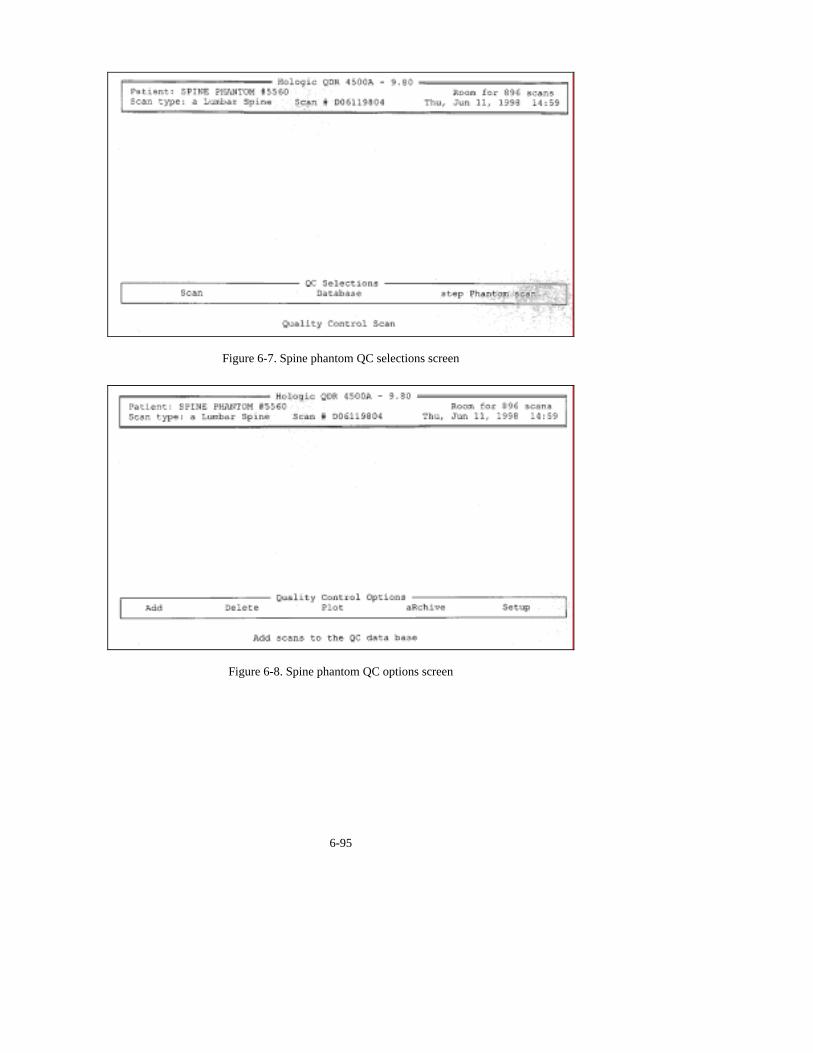
Figure 6-7. Spine phantom QC selections screen
Figure 6-8. Spine phantom QC options screen
6-95

Figure 6-9. Spine phantom QC – parameters to plot
Figure 6-10. Spine phantom QC – plot for BMC ! The circle should be within the two dotted lines.
! The CV for BMC should be at or below 0.80 percent.
! If the circle is not within the dotted lines or the CV for BMC is greater than 0.80 percent, see directions in Section 6.2.1.3.
6-96

6-97
! If the circle is within the dotted lines and the CV for BMC is at or below 0.80 percent, press ‘Esc.’
! Press ‘Esc’ four times to return to the main ‘Selections’ menu.
! Archive this scan at the end of the session with the session scans.
6.2.1.3 Procedures if the BMD is Not Within Specifications
! If the circle falls outside of the dotted lines, press ‘Esc’ and choose ‘Scan’ to rescan the phantom.
! If the circle is still outside the two dotted lines, repeat the process one more time.
! If after three attempts the results do not fall within the dotted lines, report this to the Chief Technician AND the MEC manager. This information should be reported to Hologic.
! The MEC manager is responsible for all calls, but may delegate this responsibility to the Chief Technician at his/her discretion.
! Record this call on the ‘Equipment Problem Log.’
6.2.2 Step Phantom
! At the main ‘Selections’ menu, choose QC and press ‘Enter.’
! At the ‘QC Selections’ menu choose ‘Step Phantom Scan’ and press ‘Enter.’ This will bring up the ‘Step Phantom Scan Setup’ screen. See Figure 6-11.
! When the table motion is complete, place the Body Composition Phantom lengthwise on the table with the thinnest step to your right as you face the table.
! Center the long axis of the phantom to the long axis of the laser light.
! Center the middle of the crosshair 3/4 of an inch from the right side of the thinnest step.
! Press any key to start the scan.
! At the conclusion of the scan, the step phantom is automatically analyzed and the data are stored in a separate file in the system.

Figure 6-11. Step phantom QC setup screen
! The system will display a message ‘The step phantom scan for body composition
calibration has been successfully completed.’ See Figure 6-12.
Figure 6-12. Step phantom QC – completed
! Press any key to return to the ‘QC Selections’ menu.
! Press ‘Esc’ to return to the main menu.
! Archive this scan at the end of the session with the session scans.
6.2.3 Air Scan
! Clear entire table of any objects.
! Select ‘Biography’ from ‘Main Menu.’
! Select ‘WB QC Air Scan’ from the biography list.
6-98

6-99
! CONFIRM THAT THE CORRECT BIOGRAPHY HAS BEEN SELECTED.
! Press Enter. Press F10.
! Select ‘Scan’ from Main Menu.
! Select ‘Whole Body.’
! Press F10 to begin air scan.
! When scan is completed, press ‘Esc.’
! Press Alt + F1 to exit to DOS.
! Type ‘airscan’ and press ‘Enter.’ A program will automatically analyze the airscan.
! Enter the Global Stats Standard Deviation in the ISIS QC application.
! **If the SD is greater than 2.0, see Section 6.2.3.1 for further details.
! Type ‘mainmenu’ to return to the Hologic Main Menu.
! Archive this scan at the end of the session with the session scans.
6.2.3.1 Procedure if Standard Deviation (SD) is Greater Than 2.0
! Report this to the Chief Technician AND the MEC manager.
** Chief Technician and MEC Manager:
! Check the results of the air scan and confirm that the scan procedure was completed correctly.
! Perform a second scan and note the results. If the Standard Deviation is still >2.0, call the home office to report the results of the air scan. (See laminated instruction sheets in the DXA room for the names and numbers of the people to contact.)
! If you are unable to reach anyone at the home office, contact Hologic.
! Continue doing DXA scans until further notification from the home office.
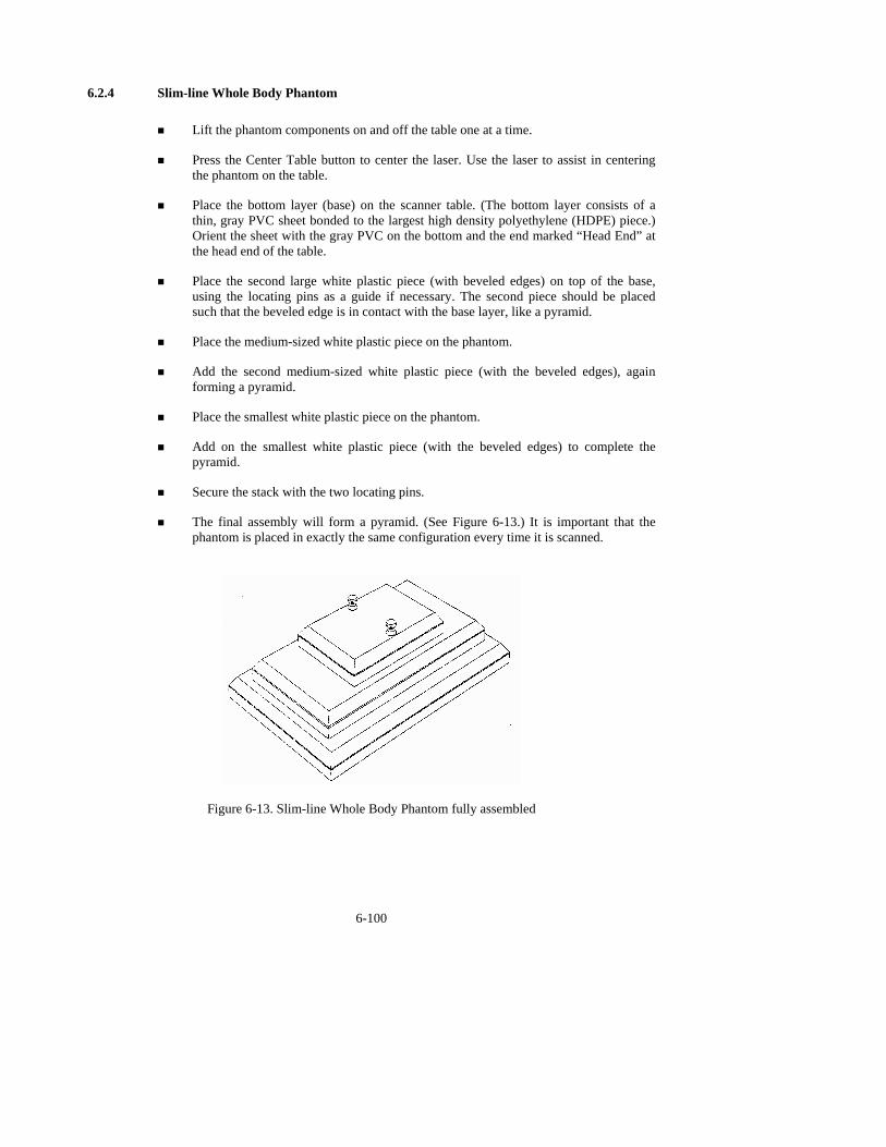
6.2.4 Slim-line Whole Body Phantom
! Lift the phantom components on and off the table one at a time.
! Press the Center Table button to center the laser. Use the laser to assist in centering the phantom on the table.
! Place the bottom layer (base) on the scanner table. (The bottom layer consists of a thin, gray PVC sheet bonded to the largest high density polyethylene (HDPE) piece.) Orient the sheet with the gray PVC on the bottom and the end marked “Head End” at the head end of the table.
! Place the second large white plastic piece (with beveled edges) on top of the base, using the locating pins as a guide if necessary. The second piece should be placed such that the beveled edge is in contact with the base layer, like a pyramid.
! Place the medium-sized white plastic piece on the phantom.
! Add the second medium-sized white plastic piece (with the beveled edges), again forming a pyramid.
! Place the smallest white plastic piece on the phantom.
! Add on the smallest white plastic piece (with the beveled edges) to complete the pyramid.
! Secure the stack with the two locating pins.
! The final assembly will form a pyramid. (See Figure 6-13.) It is important that the phantom is placed in exactly the same configuration every time it is scanned.
6-100
Figure 6-13. Slim-line Whole Body Phantom fully assembled
6-101
6.2.4.1 Phantom Positioning
! The phantom should be centered top to bottom and side to side on the table. Use the laser to assist in centering the phantom.
6.2.4.2 Scanning the Slim-line Whole Body Phantom
! Confirm that the phantom is centered, parallel with the long axis of the table, and is correctly oriented with respect to the head of the table.
! Confirm all artifacts are removed from the scanner table surface.
! On the Hologic computer screen, go to the main selections menu.
! Select Biography.
! Type ‘slim’ and press enter.
! Choose Slim-Line WB Phantom #XXXX. (XXXX is 1013 on MEC 1, 1021 on MEC 2, or 1022 on MEC 3.)
! Confirm that the correct biography has been selected.
! At the ‘Patient Biography Information’ screen, press F10.
! Select S for Scan at the main ‘Selections’ menu.
! Select ‘Whole Body.’ Press F10.
! When the scan is completed, carefully inspect the image to ensure that the phantom was centered, parallel with the long axis of the scanner table and the phantom’s head appears at the top of the image.
! If the scan is not satisfactory, reposition the phantom again, carefully following the instructions above.
! Archive the scans at the end of the session.
6.2.5 Circulating HASP (HSP Q-96)
! NOTE: This phantom is a different phantom from the one used for daily scans. Do not use the regular spine phantom that is used for daily QC scans.
! Center the table. When the table motion is complete, position the Hologic Circulating Spine Phantom on the table at the position indicated by the laser cross.
6-102
! The positioning star should be pointing to the foot of the table (your left as you face the table).
! The laser cross should be centered on the positioning star.
! The laser line should be centered on the line between the numbers 9 and 6.
! At the main ‘Selections’ menu, type P for ‘Biography’ (or highlight ‘Biography’ and press ‘Enter’).
! Type ‘Hol’ and press ‘Enter.
! Highlight ‘Hologic Spine Phantom Q-96’ from the Biography list. Press ‘Enter.’
! NOTE: Be careful to select the correct biography.
! CONFIRM THAT THE CORRECT BIOGRAPHY HAS BEEN SELECTED.
! At the ‘Patient Biography Information’ screen, press F10.
! At the main ‘Selections’ menu, type S for ‘Scan.’
! At the ‘Scan Selections’ menu, type S for ‘Spine.’
! At the ‘AP Spine Scan Selections’ menu, type F for ‘Fast array.’
! Press F10 to start the scan.
! The machine will scan the phantom.
! After the scan is completed, press ‘Esc’ to return to the main menu.
! Repeat the above steps 9 times until a total of 10 scans have been completed.
! Archive these scans at the end of the session with the session scans.
6.2.6 Circulating Block Phantom (Hologic Block Phantom NH #1)
! Center the table. When the table motion is complete, position the Hologic Circulating Spine Phantom on the table at the position indicated by the laser cross.
! The positioning star should be pointing to the foot of the table.
! The laser cross should be centered on the positioning star.
! The laser line should be positioned between the numbers 1 and 2.
! At the main ‘Selections’ menu, type P for ‘Biography’ (or highlight ‘Biography’ and press ‘Enter’).
! Type ‘Hol’ and press ‘Enter.
6-103
! Highlight ‘Hologic Block Phantom NH #1’ from the Biography list. Press ‘Enter.’
! NOTE: Be careful to select the correct biography.
! CONFIRM THAT THE CORRECT BIOGRAPHY HAS BEEN SELECTED.
! At the ‘Patient Biography Information’ screen, press F10.
! At the main ‘Selections’ menu, type S for ‘Scan.’
! At the ‘Scan Selections’ menu, type S for ‘Spine.’
! At the ‘AP Spine Scan Selections’ menu, type F for ‘Fast array.’
! Press F10 to start the scan.
! The machine will scan the phantom.
! After the scan is completed, press ‘Esc’ to return to the main menu.
! Repeat the above steps 9 times until a total of 10 scans have been completed.
! Archive these scans at the end of the session with the session scans.
6.2.7 Hologic Whole Body Phantom
6.2.7.1 Phantom Assembly:
! Lift the phantom components on and off the table one at a time.
! Refer to the diagram to assist in positioning the phantom correctly.
! Place the bottom layer (base) of the phantom on the scanner table. (The bottom layer consists of a thin gray PVC sheet attached to a large white plastic sheet that contains two plastic locating pins). Orient the serial numbers to the head end of the table.
! Position the bottom layer such that the gray PVC is on the bottom (the gray PVC is in contact with the table and the two alignment holes are facing out of the plane of the table toward the ceiling).
! Place the second large white plastic piece on top of the phantom base, using the alignment holes as a guide. This piece should be placed such that the beveled edge forms a 45 degree angle with the base, with the serial numbers oriented to the head of the table.
! Next place the medium size white plastic pieces on the phantom, with the top medium piece forming a 45 degree angle with the bottom medium piece. Make sure the serial numbers are toward the head of the table.
! Place the small white plastic pieces on top, to resemble the medium and large setup.

6-104
! Insert the locating pins through the alignment holes.
! The final assembly will form a pyramid (refer to the diagram, side view).
! Check that the phantom configuration is positioned exactly as outlined.
Phantom Positioning:
! Position the phantom in the center of the scanner table.
! Put the head of the phantom at the head of the table. (The head of the phantom is the end that has the phantom serial number label attached to it).
! Position the head of the phantom 24 inches from the head of the table.
! Carefully position the phantom parallel with the long axis of the table, using the table pad markings as a guide.
Scanning the Whole Body Phantom
! Confirm that the phantom is centered, is parallel with the long axis of the table, and is correctly oriented with respect to the head of the table.
! Confirm that all artifacts are removed from the scanner table surface.
! On the Hologic computer screen, go to the main selections menu.
! Select Biography.
! Type ‘WB’ and press ‘Enter.’
! Choose ‘WB PHANTOM #008’ (008 is the serial number of the Whole Body Phantom).

Figure 6-14. Layout of whole body phantom - top view
6-105
Figure 6-15. Layout of whole body phantom - side view
! Confirm that the correct biography has been selected.
! At the ‘Patient Biography Information’ screen, press F10.
! Select S for Scan at the main ‘Selections’ menu.
! Select ‘Whole Body.’ Press F10.
! Carefully inspect the scan image to ensure that the phantom was centered, parallel with the long axis of the scanner table and the phantom’s head appears at the top of the image.
! If the scan image is satisfactory, do four more scans without moving the phantom.
! (If the scan image was not satisfactory, reposition the phantom again carefully following the instructions above and do five scans).
! Archive the scans at the end of the session.
6-106
6.3 Calibration of Equipment for BIA
6.3.1 Automatic – Internal Circuitry Self-Check
! When the device is turned on, the device performs an internal circuitry self-check and will inform the user if the device has become out of calibration or has a fault.
! Contact the Chief Technician. If the issue isn’t resolved, contact the MEC manager.
6.3.2 Electronic Circuit Testing with Verification Module
! The TS4201 electronic verification module is used for equivalent electronic circuit testing.
! Connect each pair of the black current (AI & BI) and red voltage (AV & BV) alligator clips to the TS4201 (see Figure 2-19).
! Press Menu to confirm settings; use arrow key to view options.
! Enter “00001” as the test case number. Press Enter.
! Select ECF and ICF as object to be measured. Press Enter.
! Select WB by WRIST_ANKL as “Method” of measurement. Press Enter.
! Select SINGLE Meas as “Mode” of measurement. Press Enter.
! Enter male for “Gender.” Press Enter.
! Enter 175 cm for “Height.” Press Enter.
! Enter 70 kg for “Weight.” Press Enter.
! Press START to begin measurement.
! The display will say “Measurement in progress,” followed by “Data modeling in progress.” This will take about 1 to 1 ½ minutes.
! The results will be displayed on the Xitron screen as:
E – ECF
I – ICF
T - TBF
! The measured ECF should be between 15.88 and 16.09.
! The measured ICF should be between 29.73 and 30.36.

6-107
! The TBF is not confirmed.
! Remove the electrodes from the verification module and hang over the hook on the wall.
! Press Menu until “START to Measure/MENU to Modify” is displayed.
! Note: START is not pressed to begin an actual measurement; press Capture on ISIS screen.
6.4 QC Scan Checklists
The QC Scan checklists were developed to ensure that all QC Scans are completed as outlined in the protocol. There are two forms: one is used for all daily, 3 times/week, and weekly QC scans; the other is used for all Start of Stand QC scans. See Appendixes E and F for sample forms.
6.4.1 Instructions for Completing Weekly QC Scan Checklist
! The checklist should be filled out on each day of the workweek by the health technician who is responsible for completing the QC scans that week.
! As scans are completed each day, check the appropriate boxes.
! During the week, keep the checklist in the Body Composition Procedures manual. At the end of each week, file the completed form in the ‘Weekly QC Scans Checklist’ section in the back of the manual, behind the previous week’s form.
6.4.2 Instructions for Completing Start of Stand QC Scan Checklist
! The checklist should be filled out at the start of the stand by the health technician who is responsible for completing the start of stand scans.
! As each scan is completed, check the appropriate box.
! File the completed form in the ‘Start of Stand QC Scans Checklist’ section in the back of the manual, behind the form from the previous stand.
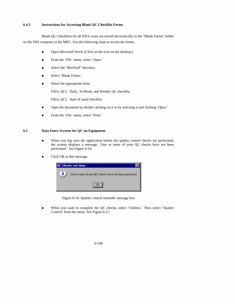
6.4.3 Instructions for Accessing Blank QC Checklist Forms
Blank QC Checklists for all DXA scans are stored electronically in the “Blank Forms” folder on the ISIS computer in the MEC. Use the following steps to access the forms.
! Open Microsoft Word. (Click on the icon on the desktop.)
! From the ‘File’ menu, select ‘Open.’
! Select the ‘MecStaff’ directory.
! Select ‘Blank Forms.’
! Select the appropriate form:
DXA_QC1 Daily, 3x/Week, and Weekly QC checklist
DXA_QC2 Start of stand checklist
! Open the document by double clicking on it or by selecting it and clicking ‘Open.’
! From the ‘File’ menu, select ‘Print.’
6.5 Data Entry Screens for QC on Equipment
! When you log onto the application before the quality control checks are performed, the system displays a message: ‘One or more of your QC checks have not been performed.’ See Figure 6-16.
! Click OK to this message.
Figure 6-16. Quality control reminder message box
! When you want to complete the QC checks, select ‘Utilities.’ Then select ‘Quality
Control’ from the menu. See Figure 6-17.
6-108

Figure 6-17. Utilities menu to select quality control
! Clicking on the QC icon from the Toolbar can also access the QC screens.
! When QC is selected from the Utilities menu, the User ID entry box will be displayed. See Figure 6-18.
Figure 6-18. Quality control log-on
! Each technician will have a personal ID. This ID will be used to identify the person
who completed the QC checks for this time period.
! Enter your User ID and click OK.
! If you do not want to do the QC checks at this time, click Cancel.
6-109

6.5.1 Daily QC Checks
The Daily QC check data entry screen is shown in Figures 6-19 and 6-20.
Figure 6-19. Quality control daily checks (1)
Figure 6-20. Quality control daily checks (2)
! On the QC screens, check ‘Done’ for the listed items when that item has been
completed.
! You are not required to enter anything in the ‘Result’ or ‘Comment’ fields unless there is a problem.
! The ‘Result’ field is used to enter values for selected QC items if required.
6-110

! The ‘Comments’ field is used to enter information about problems encountered with the QC item check.
! Use the scroll bar to move to the remaining items.
! When you are finished with the daily item checks, click OK to close the QC box.
6.5.2 Weekly QC Checks
! The Weekly QC Check Data Entry screen is shown in Figures 6-21, 6-22, and 6-23.
! Complete all the daily checks.
6-111
Figure 6-21. Quality control weekly checks (1)

Figure 6-22. Quality control weekly checks (2)
Figure 6-23. Quality control weekly checks (3)
! Check ‘Done’ for each item on the weekly checks when complete.
! Use the Scroll down bar on the right of the screen to get to the remaining items.
! If you notice a problem with any of the items on the check list, make a note of this in the comment box and report it to the MEC manager.
6.5.3 Start of Stand QC Checks
! The Start of Stand QC Check data entry screen is shown in Figures 6-24 and 6-25.
6-112
Figure 6-24. Quality control stand checks (1)

Figure 6-25. Quality control stand checks (2)
! Complete all ‘Start of Stand’ checks.
! ‘Start of Stand’ checks include all daily and weekly checks.
! When the ‘Start of Stand’ checks are complete, click OK to close the QC checks.
! Complete the remaining ‘Start of Stand’ checks.
! When you have completed all checks, click OK to close the QC box.
6.5.4 End of Stand QC Checks
! Clean the DXA table by wiping it down with a clean damp cloth and liquid Ivory™ soap. Do not complete this item until all exams for the stand have been completed to ensure that no scans are done on a damp table. See Figure 6-26.
6-113
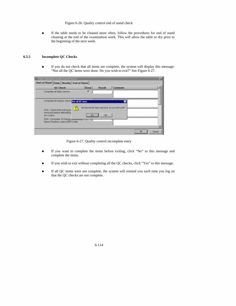
Figure 6-26. Quality control end of stand check
! If the table needs to be cleaned more often, follow the procedures for end of stand
cleaning at the end of the examination week. This will allow the table to dry prior to the beginning of the next week.
6.5.5 Incomplete QC Checks
! If you do not check that all items are complete, the system will display this message: “Not all the QC items were done. Do you wish to exit?” See Figure 6-27.
Figure 6-27. Quality control incomplete entry
! If you want to complete the items before exiting, click “No” to this message and
complete the items.
! If you wish to exit without completing all the QC checks, click “Yes” to this message.
! If all QC items were not complete, the system will remind you each time you log on that the QC checks are not complete.
6-114

A-115
APPENDIX A
BODY COMPOSITION (DXA/BIA) SCRIPTS
Introduction to the component: In this room we are going to do two exams. One exam can
tell us something about how strong your bones are and how much body fat you have. The other exam measures the amount of water in your body. I will explain each exam in more detail as I do it. Please lie down on the table and get as comfortable as possible. I am going to ask you a few questions before I start the exam.
Explanation of DXA: (Technician is positioning examinee during this explanation. This is
an explanation, not a standard script so the technician may adjust the explanation to the level of understanding of the examinee. This is provided as a guideline only.) For this exam I will be doing a scan
of your body with this machine. The exam lasts three minutes and you will not feel anything except for the table movement. I need you to lie straight on the table with your hands by your sides. I am attaching this velcro strap around your feet to hold them in this position for the exam. As the machine scans your body, the table will move up and down and back and forth. This arm (the C-arm) will also be moving.
During the exam please lie perfectly still if possible. This scan will provide us with your bone mineral density which can tell us how strong your
bones are compared to other people like you. It can also give us a measurement of how much body fat
you have. You will receive this information in a few weeks. Consent for Second DXA Scan: (This is a standard script which is to be read as written to
the SP, when applicable, to obtain permission to obtain a second DXA scan.) The image quality of your
whole body scan is not adequate for reporting your bone density results. I see from your scan that [fill in the problem observed]. With your permission, I would like to repeat the scan to improve the image quality. The amount of radiation from this scan is about 1 millirem, or the amount you would receive for 2 hours on a coast-to-coast airplane flight. This scan is voluntary and there is no penalty for refusing. Do I
have your permission to repeat the scan?

A-116
Explanation of BIA: (Technician is positioning examinee during this explanation. This is an explanation, not a standard script so the technician may adjust the explanation to the level of understanding of the examinee. This is provided as a guideline only.) This next exam will only take another minute and you will not feel anything during the measurement. I am going to wipe off your right
hand and foot with an alcohol swab and attach these four electrodes (or patches). I will connect the electrodes to this machine and start the measurement. The machine will send a very small current through the electrodes but it is at such a low level that you will not be able to feel it. The measurement will take only a minute. The machine measures the amount of water in your body (the amount of water inside and
outside of your cells).

A-117
BODY COMPOSITION (DXA/BIA) SPANISH VERSION
Introduction to the component: En este cuarto vamos a hacer dos exámenes. Un examen nos puede decir algo acerca de qué tan fuerte están sus huesos y cuanta grasa tiene en el cuerpo. El otro examen mide la cantidad de agua que tiene en el cuerpo. Explicaré cada examen con mayor detalle
mientras los haga. Por favor acuéstese en la mesa y póngase tan cómodo como sea posible. Le voy a hacer algunas preguntas antes de empezar el examen.
Explanation of DXA: (Technician is positioning examinee during this explanation. This is
an explanation, not a standard script so the technician may adjust the explanation to the level of understanding of the examinee. This is provided as a guideline only.) Para este examen le haré un escáner del cuerpo con esta máquina. El examen dura tres minutos y usted no sentirá nada excepto por el movimiento de la mesa. Necesito que se acueste derecho en la mesa con las manos a los lados. Le estoy
poniendo esta cinta “Velcro” alrededor de los pies para mantenerlos en esta posición durante el examen. A medida que la máquina explore su cuerpo, la mesa se moverá hacia arriba y hacia abajo y de atrás para delante. Este brazo (the C-arm) también se estará moviendo. Durante el examen por favor acuéstese perfectamente quieto si es posible.
Este escáner nos proporcionará la densidad mineral de sus huesos lo cual nos puede decir
qué tan fuertes están sus huesos comparados con los de otras personas como usted. También nos puede dar una medición de cuanta grasa tiene en el cuerpo. Usted recibirá esta información en unas pocas
semanas Consent for Second DXA Scan: (This is a standard script which is to be read as written to
the SP, when applicable, to obtain permission to obtain a second DXA scan.) La calidad de la imagen del
escáner de todo su cuerpo no es adecuada para informar el resultado de la densidad de los huesos. Veo por su escáner que [fill in the problem observed]. Con su autorización, quisiera repetir el escáner para mejorar la calidad de la imagen. La cantidad de radiación de este escáner es 1 milirem, o sea, la cantidad que usted recibiría en un vuelo en avión de dos horas de costa a costa. Este escáner es voluntario y no hay
consecuencias negativas por rehusar. ¿Me da su autorización para repetir el escáner? Explanation of BIA: (Technician is positioning examinee during this explanation. This is an
explanation, not a standard script so the technician may adjust the explanation to the level of
understanding of the examinee. This is provided as a guideline only.) Este próximo examen tomará otro minuto solamente y usted no sentirá nada durante la medición. Voy a limpiarle la mano y el pie derecho con una mota de algodón con alcohol y le voy a poner estos cuatro electrodos (o parches). Conectaré los

A-118
electrodos a esta máquina y empezará la medición. La máquina mandará una corriente muy pequeña a través de los electrodos, pero ésta es de tan bajo nivel que usted no la podrá sentir. La medición tomará un minuto solamente. La máquina mide la cantidad de agua que tiene en el cuerpo (la cantidad de agua dentro y fuera de las células).

B-119
APPENDIX B
SAFETY/EXCLUSION QUESTIONS (SPANISH TRANSLATION)
Shared Exclusion Questions:
Do you have any amputations of your legs and feet other than toes?
•Tiene usted alguna amputación de las piernas o de los pies que no sea en los dedos de los pies?
Where is the amputation?
•Dónde es la amputación?
How much do you weigh without clothes or shoes?
¿Cuánto pesa sin ropa y sin zapatos?
Do you have a pacemaker or automatic defibrillator?
¿Tiene un marcapaso o un defribilador automático?
Are you currently pregnant?
¿Está usted actualmente embarazada?
How many weeks?
¿Cuántas semanas?
(Instruction to SP) Please remove any jewelry from your body and hair.
Por favor párese en la pesa para que lo pueda pesar.
Safety/Exclusion Questions:
Do you have any artificial joints, pins, plates, or other types of metal objects in your body?
¿Tienen usted alguna (articulación/coyuntura)artificial, un clavo ortopédico, placa artificial u otro tipo de objetos de metal en el cuerpo?
Do you have any coronary stents or metal suture material in your heart?
¿Tiene usted alguna "stents" coronaria o material de metal para sutura en el corazón?
Have you had any X-ray with contrast material such as barium in the past 7 days?
¿Le han tomado una radiografía con material de contraste tal como barium en los 7 días pasados

B-120
Have you had any nuclear medicine studies in the past 3 days?
¿Le han hecho algún estudio en que usaran medicina nuclear en los 3 días pasados?
C-121
APPENDIX C
SET-UP AND TEAR-DOWN PROCEDURES FOR BODY COMPOSITION ROOM
Set-up Procedures
DXA set-up:
! Get Room Supply Sheet from Setup and Tear-Down Procedures Binder and put the supplies in the room, the room supply box, and the black belly box as indicated.
! Do not overstock the room. There should be sufficient supplies kept in the room to do several day to a week of exams.
! Remove locking pin from base of C-arm
! Remove Velcro straps from pillar under C-arm
! Remove pillar from bed of DXA and store pillar in Body Composition Box in MEC belly
! Remove signs from C-arm and Hologic monitor indicating C-arm is locked. Put signs in Setup/Tear-down binder.
! C-arm must be unbolted from locking pins before any attempt is made to move C-arm
CPU cart set-up and tie-down material removal:
! Remove tie down strap from CPU cart and from wall anchors
! Remove wall anchors (2) from walls
! Store tie down strap and wall anchors in their container and store container in DXA/BIA supply box
! Check that ISIS CPU, ISIS keyboard, Hologic CPU, and Hologic monitor are still secured to CPU cart
! Check that DXA UPS, phantom boxes, and DXA machine are still secured to the floor
Computer equipment and Xitron set-up:
! Unpack ISIS monitor from box and place on CPU cart
! Unpack printer from box and place on CPU cart

C-122
! Remove Hologic keyboard and mice from box and place on CPU cart
! Unbolt sliding shelf for Hologic keyboard
! Connect all computer equipment on CPU cart to CPU
! Replace Xitron analyzer shelf
! Unpack Xitron analyzer, verification module, patient cable, and power cord from Xitron box
! Place Xitron analyzer on its shelf, secure with Velcro strap, and connect to CPU and power source
! Store boxes for computer equipment (should be labeled DXA/BIA) in MEC belly during a stand
Supply set-up:
! Connect telephone receiver to telephone and plug telephone into wall jack
! Unpack binders for DXA/BIA room and place on basket in grid
! Unpack grid baskets from box and hang on wall grid
! Restock containers in grid baskets where needed
! Store Sani-wipe dispenser on the floor
! Place new velcro foot strap in grid basket; discard used strap
! Check amount of paper on DXA bed roller; replace if needed
! Restore trash can and chair to upright positions
! Store DXA/BIA supply box in MEC belly during a stand
MEC Manager/Chief Technician:
! Make a final check on room set-up with technician
Tear-down Procedures
Technician:
! Remove wall anchors and tie down straps from supply box stored in MEC belly
! Attach all wall anchors to the walls

C-123
! Attach the long end of the strap to the wall anchor on the telephone wall, and attach the ratchet strap to the opposite corner wall anchor
! Pack manuals into DXA/BIA supply box
! Consolidate supplies in grid baskets where possible and pack grid baskets with supplies into DXA/BIA supply box
! Empty grid baskets may be left on the grid.
! Put wipe dispenser in a plastic bag and pack into supply box
! Disconnect power cord from BIA analyzer, wrap power cord into a long loop and wrap Velcro around loop
! Disconnect patient cable from adapter and wrap cable into a long loop
! Unscrew computer cable from BIA analyzer
! Remove BIA analyzer from shelf and wrap Velcro strap around shelf
! Wrap BIA analyzer in bubble wrap and pack in its own box
! Store patient cable, power cord, and adapter in BIA analyzer box on top of analyzer
! Store BIA analyzer box in DXA supply box on opposite side of wipe dispenser bags
! Remove BIA shelf from shelf brackets
! Store shelf in DXA/BIA supply box
! Place extra paper roll in supply box
! Disconnect telephone from phone jack and disconnect telephone receiver
! Wrap telephone receiver in packing material and store in DXA/BIA supply box
! Store packed DXA/BIA supply box on floor. Nothing should be stored on the table.
! Center C-arm and DXA table.
! *** Bolt C-arm with locking pins at the base of the C-arm (Chief Tech or Advance Arrangements Staff should assist with this step).
! *** Position pillar under outside edge of C-arm. Use caution when doing this. The C-arm should not be forced out of position. (Chief Tech or Advance Arrangements Staff should assist with this step).
! Secure pillar to C-arm with Velcro straps
! Post sign on Hologic monitor and C-arm: “Locking pins are in position. Do not attempt to turn on DXA machine until the locking pin is removed.”

C-124
! Anchor computer cart with nylon strap around cart legs and tighten ratchet
! Check that the ISIS CPU, the ISIS keyboard, the Hologic CPU and the Hologic monitor are all secured to the computer cart
! Check that the UPS, the phantom boxes, and the DXA are secured to the floor
! Turn room chair upside down
! Turn trash can on its side
Chief Technician/MEC Manager:
! Make final check on pack-up of the room with the technician
Data Manager:
! Disconnect ISIS monitor and printer from CPU
! Remove ISIS monitor from cart and place in box with packing material
! Remove printer from cart and place in box with packing material
! Disconnect both mice and Hologic keyboard from CPU
! Pack the mice and the Hologic keyboard into a box with packing material
! Place all packed boxes on the floor. Nothing should be stored on the bed of the DXA
! Bolt sliding shelf for Hologic keyboard with sliding pin
! Unplug all electrical equipment
NOTE: The MEC Manager is the back-up person for all computer and biomedical equipment tear-down tasks.

D-125
APPENDIX D
USE ONE FORM FOR EACH SCANNER IN THIS STUDY THIS FORM ONLY PERTAINS TO STUDIES IN WHICH DXA DATA ARE SENT TO USCF. HOLOGIC SCANNER OPERATORS SHOULD SEND THIS FORM ALONG WITH QC ARCHIVE OR dBARCHIVE DISKETTE(S) AND BMD, BMC, AND AREA PLOTS FOR THE MOST RECENT SIX MONTHS.
DXA Bone Densitometer Report " NHANES IV MEC number (1, 2, or 3) _________________ Scanner Serial Number ____________ Hologic Spine Phantom Number __________________ 1) Has a new / different scanner been used for any study patients? Yes # No # If yes, circle Was scanner change approved in advance by UCSF? Yes # No # By Whom? ___________ 2) Has there been any software changes? Yes # No # If yes, indicate: ________ Old software version: ________ New software version: ________ Date installed: ___________ Was software change approved in advance by UCSF? Yes # No # By Whom? _______. 3) Were there any technologist changes? Yes # No # If yes:
Technologist
Added / Departed
Date of Change
Date of Manufacturer’s Training
4) Were there any maintenance/recalibration/repair problems? Yes # No # If yes, indicate:
Service Performed Date of Service 5) Additional comments (Use reverse side if necessary): Main Technologist: _____________________________ Date: ____________ Telephone: __________ Please make copies of this blank form. Compete this form each reporting period and send the original to the UCSF Quality Assurance Center and keep a copy for your records.
D-126
DXA Bone Densitometer Service Report
When the Hologic densitometer is serviced or repaired: ! The Chief Technician will complete a 'DXA Bone Densitometer Report'.
! Fax a copy of the report to the Home Office. See laminated cards in the DXA room for names and fax numbers. The Home Office will send this to the Quality Control Reading Laboratory.
! Fax a copy of the Service Report completed by the Service Engineer when the repair or service was made to the Home Office and to the Reading Laboratory.
! Put a copy of the Service Engineer's report and a copy of the DXA Bone Densitometer in the Service Report binder kept in the DXA room.

D-127
APPENDIX E Start of Stand QC Scan Checklist
Stand#:_______ Tech ID#:______ Scale Check [(your wt + dumbbell) – your w
Type of Scan
Scan 1
Spine Phantom
Step Phantom
Air Scan Global Stats SD= ______
Scan 2 Scan 3 Scan 4 Scan 5
Hologic Slim-line Whole Body Phantom (Slim-line WB Phantom #XXXX)
Hologic Whole Body Phantom (WB Phantom #008)
Scan 6 Scan 7 Sc
Circulating Spine Phantom (HSP Q96)
Circulating Block Phantom

DXA-QC1
E-128
128
(nhanes Block #1)

APPENDIX F
WEEKLY QC SCAN CHECKLIST
Week of: ___________________ Tech ID#:____________________ Please note: For Day 1 of the first week of each stand, it is not necessary to repeat scans that were done as part of the Start of Stand QC.
Daily:
Day 1 Day 2 Day 3 Day 4 Day 5 Day 6 (if applicable)
Type of Scan
Scan 1 Scan 1 Scan 1 Scan 1 Scan 1 Scan 1
Spine Phantom (HASP)
Slim-line Whole Body Phantom
Step Phantom (HASP)
WB QC Air Scan Global Stats SD=_____
Comment: Leave format as is. (Check ore making changes)with Charlotte bef
D-129

DXA-QC2
F-130

G-131
APPENDIX G
PROCEDURE FOR SECURING THE QDR 4500A FOR TRAVEL
POSITION TABLE & NORMAL SHUTDOWN CHIEF TECHNICIAN
! Press 'Center Table' switch on the Control Panel to position the C-arm and table in the middle of its range.
! Complete the normal shutdown procedures.
! Press Shutdown.
! When prompted, turn the X-ray Enable key off and put the key in the Spine Phantom box.
! Turn the Computer Power switch off (the small button on the right side of the CPU). Do not press the button on the front of the CPU.
! Turn the Instrument Power Switch to the OFF position (O).
! Switch off the QDR 4500 Main Power Switch (located on back panel at the bottom of panel).
TURN OFF UPS ADVANCE TEAM/DATA MANAGER
! Switch the UPS STOP/RUN switch to STOP.
! Switch off the UPS main breaker.
INSTALL C-ARM STABILIZER CHIEF TECHNICIAN/ADVANCE TEAM
! Carefully complete the following steps. The stabilizer fits snugly between the C-arm and the table but it should not be forced.
! Place the notched end of the Stabilizer on the bottom of the C-arm (tank end) and pivot the top towards the top of the C-arm.
! Position the Stabilizer so that the top, and bottom, foam pads are wedged between the top of the tank cover and the bottom of the C-arm.
! The C-arm must be vertical.
! Secure Stabilizer by clamping the Velcro strap tightly around the top of the C-arm and fasten it to the Stabilizer pad.

DXA-QC2
G-132
SECURE C-ARM ROTATION LOCK CHIEF TECHNICIAN/ADVANCE TEAM
! The C-arm Rotation Lock is located on the bottom left side of the C-arm (facing the scanner), behind the black shock absorber.
! Turn the handle of the lock until the plunger releases and locks into place.
! The Carriage Lock is located on the lower left side of the carriage.
! Turn the handle until the plunger releases and locks into place.
! Put pink neon signs on C-arm and over Hologic Computer screens that indicate that the locking pins are in position.

H-133
APPENDIX H
PROCEDURE FOR SETTING UP QDR 4500A FOR OPERATIONS
UNLOCK CARRIAGE & ROTATION LOCKS: ADVANCE TEAM /CHIEF TECH
! Unlock the Carriage Lock
! Unlock the C- arm rotation Lock.
! Remove the pink neon signs from the C-Arm and Hologic computer screen and return to Body Composition Manual
REMOVE C- ARM STABILIZER CHIEF TECHNICIAN/ADVANCE TEAM
! Remove the Velcro strap from the Stabilizer
! Gently remove the Stabilizer from its position.
! The Stabilizer is stored in the black belly box during the Stand.
POWER UP THE QDR 4500 SYSTEM ADVANCE TEAM/DATA MANAGER
Note: The QDR 4500 X-ray Bone Densitometer System should only be shut down when necessary, primarily during road travel. Other than during road travel, the system should remain powered whenever possible, to avoid warm-up delays. Failure to follow this procedure may cause the UPS batteries to discharge and require significant recharge time.
! Verify that the QDR 4500 main breaker is OFF, the UPS main breaker is OFF and the UPS
Stop/RUN Switch is in the STOP position.
! Plug in the QDR 4500 Power Module into one of the UPS outlets.
! Plug in the UPS into a live power outlet (shore power or motor generator).
! If running on motor generator and generator is off, start the motor generator. If running on shore power, verify that the shore power link is ON.
! Switch on the UPS main breaker and wait 30 seconds. Verify that the AC line light on the UPS is lit.
! Switch the UPS STOP/RUN switch to RUN and wait for the end of the second long beep. Verify that the INVERTER light on the UPS is lit.

DXA-QC2
H-134
! If the UPS batteries are discharged, wait until the batteries are charged. (If you switch on the QDR 4500 without waiting for the batteries to charge, you will lose power outage protection).
! Turn on the QDR 4500 Power Switch (located on the BACK PANEL AT THE BOTTOM LEFT OF THE PANEL if you are facing the panel.)
POSITION TABLE AND POWER ON TECHNICIAN
Carefully follow the Startup Procedures (step by step) for Hologic QDR (beginning of session).
! Check the Power On lamp on the Power Switch is on.
! Turn the Instrument Power Switch to the ON position.
! Allow 30 minutes warm-up time.
! Turn the X-ray Enable key to the ON position.
! Turn the Computer Power switch to the ON position. (Do not use the button on the front of the CPU.
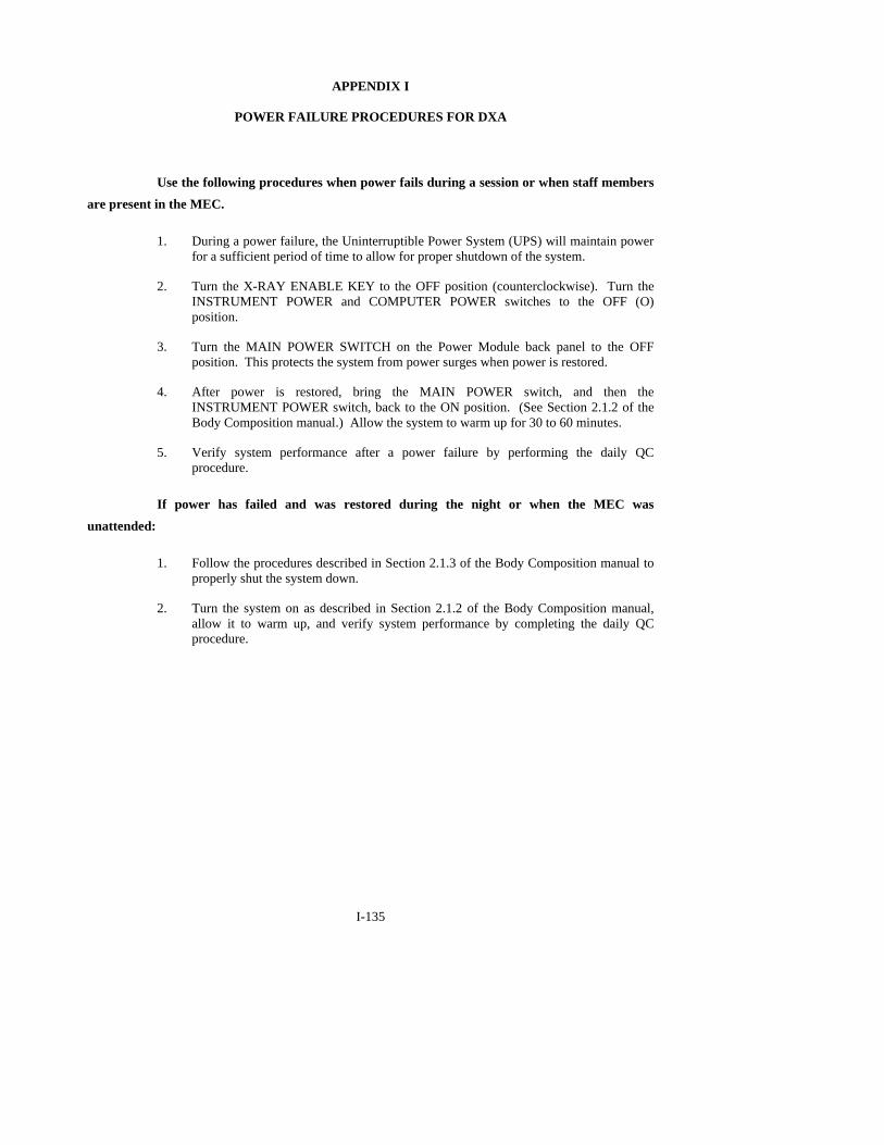
I-135
APPENDIX I
POWER FAILURE PROCEDURES FOR DXA
Use the following procedures when power fails during a session or when staff members are present in the MEC.
1. During a power failure, the Uninterruptible Power System (UPS) will maintain power
for a sufficient period of time to allow for proper shutdown of the system.
2. Turn the X-RAY ENABLE KEY to the OFF position (counterclockwise). Turn the INSTRUMENT POWER and COMPUTER POWER switches to the OFF (O) position.
3. Turn the MAIN POWER SWITCH on the Power Module back panel to the OFF position. This protects the system from power surges when power is restored.
4. After power is restored, bring the MAIN POWER switch, and then the INSTRUMENT POWER switch, back to the ON position. (See Section 2.1.2 of the Body Composition manual.) Allow the system to warm up for 30 to 60 minutes.
5. Verify system performance after a power failure by performing the daily QC procedure.
If power has failed and was restored during the night or when the MEC was unattended:
1. Follow the procedures described in Section 2.1.3 of the Body Composition manual to
properly shut the system down.
2. Turn the system on as described in Section 2.1.2 of the Body Composition manual, allow it to warm up, and verify system performance by completing the daily QC procedure.

J-136
APPENDIX J
CROSS CALIBRATION SCANS - IN-VIVO WHOLE BODY SCANS START OF SURVEY AND AS DIRECTED
At the beginning of the survey, 10-20 volunteers from NCHS and Westat were scanned in all three MECs to obtain cross calibration data on the three scanners. These cross calibration scans may be
repeated at some time during the survey. The procedures for scanning are very similar to the procedures for the survey participants. The main difference in the procedures is that the volunteer is positioned optimally for the first scan and distances between the scan limit borders and the head, fingers, and toes are measured and recorded. These measurements are taken to the other two MECs and the volunteer is
positioned as close as possible to the first position. A printout of the scan image is also taken at the first MEC to aid the technician doing the scans to replicate the original position.
Name ID #
DOB Sex
MEC 1 Date/time
MEC 2 Date/time
MEC 3 Date/time
Space at head
Space at fingers
Space at feet Comments
Volunteer information for in-vivo cross calibration scans
! Scan 10-20 volunteers in each of the 3 MECs.
! Ask SPs to avoid eating a large meal prior to the scans.
! For each volunteer, the three scans should be completed at approximately the same time of day.
! All three scans for each volunteer should be completed within several days to a week.
! Assign an ID number to each volunteer. Enter the name and ID # in the table above.
! Enter the date and time of the scan for the appropriate MEC.
! Position the volunteer on the scanner table using the same protocol used for the study SP scans. (SP should be in a gown and remove all jewelry, hair ornaments, and items from the pockets).
! In addition, measure the distance between the scan field border at the head of the scanner and the top of the volunteer's head. Record this number.

DXA-QC2
J-137
! Measure the distance between the outer edge of the small finger and the scan table border. Record this number.
! Measure the distance between the toes. Record this number.
! Enter QC xxxxxx in the Name field. (xxxxxx is the volunteer's ID number).
! Enter MEC x in the comment field where x is the MEC number.
! Enter the DOB of the volunteer in the DOB field.
! Enter the sex of the volunteer in the Gender field
! Press F10.
! Select 'Scan' and then select 'Whole Body.'
! Press F10 to start the scan.
! When the scan is completed, get a screen shot of the scan image and use this to assist in positioning the volunteer in exactly the same position in the other two MECs.
! Use the measurements of spaces at the head, fingers, and toes to assist in positioning.
! Archive the scans and send to the reading lab.
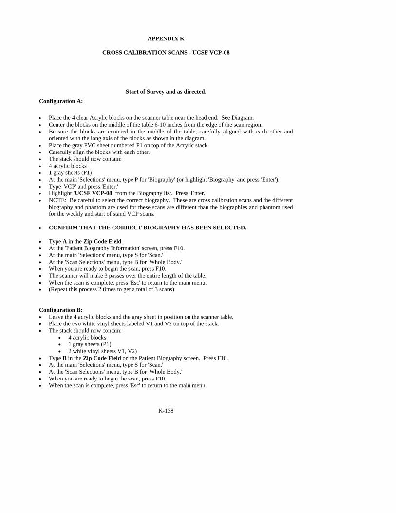
K-138
APPENDIX K
CROSS CALIBRATION SCANS - UCSF VCP-08
Start of Survey and as directed. Configuration A:
• Place the 4 clear Acrylic blocks on the scanner table near the head end. See Diagram. • Center the blocks on the middle of the table 6-10 inches from the edge of the scan region. • Be sure the blocks are centered in the middle of the table, carefully aligned with each other and
oriented with the long axis of the blocks as shown in the diagram. • Place the gray PVC sheet numbered P1 on top of the Acrylic stack. • Carefully align the blocks with each other. • The stack should now contain: • 4 acrylic blocks • 1 gray sheets (P1) • At the main 'Selections' menu, type P for 'Biography' (or highlight 'Biography' and press 'Enter'). • Type 'VCP' and press 'Enter.' • Highlight 'UCSF VCP-08' from the Biography list. Press 'Enter.' • NOTE: Be careful to select the correct biography. These are cross calibration scans and the different
biography and phantom are used for these scans are different than the biographies and phantom used for the weekly and start of stand VCP scans.
• CONFIRM THAT THE CORRECT BIOGRAPHY HAS BEEN SELECTED. • Type A in the Zip Code Field. • At the 'Patient Biography Information' screen, press F10. • At the main 'Selections' menu, type S for 'Scan.' • At the 'Scan Selections' menu, type B for 'Whole Body.' • When you are ready to begin the scan, press F10. • The scanner will make 3 passes over the entire length of the table. • When the scan is complete, press 'Esc' to return to the main menu. • (Repeat this process 2 times to get a total of 3 scans). Configuration B: • Leave the 4 acrylic blocks and the gray sheet in position on the scanner table. • Place the two white vinyl sheets labeled V1 and V2 on top of the stack. • The stack should now contain:
• 4 acrylic blocks • 1 gray sheets (P1) • 2 white vinyl sheets V1, V2)
• Type B in the Zip Code Field on the Patient Biography screen. Press F10. • At the main 'Selections' menu, type S for 'Scan.' • At the 'Scan Selections' menu, type B for 'Whole Body.' • When you are ready to begin the scan, press F10. • When the scan is complete, press 'Esc' to return to the main menu.

139
K-139
• (Repeat this process 2 times to get a total of 3 scans). Configuration C: • Leave the 4 acrylic blocks in position on the scanner table. • Remove the two white vinyl sheets. • Place the two gray PVC sheets (P1 and P2) on top of the acrylic blocks. • The stack should now contain:
• 4 acrylic blocks • 2 gray sheets (P1, P2)
• Type C in the Zip Code Field on the Patient Biography screen. Press F10. • At the main 'Selections' menu, type S for 'Scan.' • At the 'Scan Selections' menu, type B for 'Whole Body.' • When you are ready to begin the scan, press F10. • When the scan is complete, press 'Esc' to return to the main menu. • (Repeat this process 2 times to get a total of 3 scans). Configuration D: • Leave the 4 acrylic blocks and the 2 gray sheets in position on the scanner table. • Place the two white vinyl sheets labeled V1 and V2 on top of the stack. • The stack should now contain:
• 4 acrylic blocks • 2 gray sheets (P1, P2) • 2 white vinyl sheets V1, V2)
• Type D in the Zip Code Field on the Patient Biography screen. Press F10. • At the main 'Selections' menu, type S for 'Scan.' • At the 'Scan Selections' menu, type B for 'Whole Body.' • When you are ready to begin the scan, press F10. • When the scan is complete, press 'Esc' to return to the main menu. • (Repeat this process 2 times to get a total of 3 scans). Configuration E: • Leave the 4 acrylic blocks, the 2 gray sheets and 2 white sheets in position on the scanner table. • Place the remaining two white vinyl sheets labeled V3 and V4 on top of the stack. • The stack should now contain:
• 4 acrylic blocks • 2 gray sheets (P1, P2) • 4 white vinyl sheets (V1, V2, V3, & V4)
• Type E in the Zip Code Field on the Patient Biography screen. Press F10. • At the main 'Selections' menu, type S for 'Scan.' • At the 'Scan Selections' menu, type B for 'Whole Body.' • When you are ready to begin the scan, press F10. • When the scan is complete, press 'Esc' to return to the main menu. • (Repeat this process 2 times to get a total of 3 scans). • Archive all these scans at the end of the session with the session scans.

K-140
140
Overview of blocks used for each configuration
Configuration # blocks of Acrylic # sheets of gray PVC
# sheets of white vinyl
~ % fat for QDR 4500
A 4 1: P1 0 39.5
B 4 1: P1 2 (V1, V2) 32.5
C 4 2: P1, P2 0 23.5
D 4 2: P1, P2 2 (V1, V2) 16.5
E 4 2: P1, P2 4 (V1, V2, V3, V4) 11.0
View of scanner table showing VCP placement
C-arm controls
C-arm
Acrylic blocks