body composition procedures manual 2011 - cdc.gov...1. overview of body composition . body...
TRANSCRIPT

Body Composition Procedures Manual
2011-2012

iii
TABLE OF CONTENTS
Chapter Page
1 OVERVIEW OF BODY COMPOSITION ..................................................... 1-1
1.1 Overview of Dual Energy X-Ray Absorptiometry ............................. 1-1 1.2 Personnel ............................................................................................. 1-2
2 EQUIPMENT/SUPPLIES/MATERIALS ....................................................... 2-1
2.1 Description of Equipment for DXA .................................................... 2-1
2.1.1 Hologic Discovery A ........................................................... 2-1 2.1.2 Discovery QDR System Operations .................................... 2-4 2.1.3 Supplies ............................................................................... 2-4 2.1.4 Radiation Badges ................................................................ 2-4
2.2 Maintenance/Repair of Equipment for DXA ...................................... 2-4
2.2.1 DXA Bone Densitometer Service Report ........................... 2-5
2.3 Calibration of Equipment for DXA .................................................... 2-5
3 PROTOCOL .................................................................................................... 3-1
3.1 Introduction to the DXA Examination ................................................ 3-1 3.2 Explanation of the DXA Examination ................................................ 3-1 3.3 Discovery A Table and Discovery QDR System Operation ............... 3-2
3.3.1 Startup Procedures for Hologic Discovery A Table (Start of Session) ....................................................... 3-3 3.3.2 End of Session Shutdown Procedures for Discovery QDR System ...................................................... 3-6 3.3.3 End of Day Shutdown Procedures for Discovery QDR System ...................................................... 3-6
3.4 Examinee Preparation for the DXA Examination............................... 3-7
3.4.1 Measurement of Weight and Height to Determine Body Mass Index................................................................. 3-7 3.4.2 Positioning .......................................................................... 3-9
3.5 Whole Body DXA Scan ...................................................................... 3-13
3.5.1 Selecting an SP .................................................................... 3-14 3.5.2 Selecting the Type of Scan .................................................. 3-16

iv
TABLE OF CONTENTS (continued)
Chapter Page
3.5.3 Completing the Scan ........................................................... 3-17
3.6 DXA Scan Data .................................................................................. 3-20
4 DATA ENTRY SCREENS.............................................................................. 4-1
4.1 Shared Exclusion Questions ............................................................... 4-1 4.2 Weight/Height Entry Screen ............................................................... 4-6 4.3 Screening Questions ........................................................................... 4-8 4.4 DXA Whole Body Data Capture Screen ............................................ 4-10 4.5 DXA Component Status .................................................................... 4-14 4.6 Session PickUp List ............................................................................ 4-17 4.7 Session Preview Report ...................................................................... 4-18 4.8 Room Log ........................................................................................... 4-19 4.9 Close Exam ......................................................................................... 4-20
5 REFERRALS AND REPORT OF FINDINGS ............................................... 5-1
5.1 Observation Referrals ......................................................................... 5-1 5.2 Report of Findings for Body Composition ......................................... 5-3
5.2.1 Sample Preliminary Report of Findings .............................. 5-4
6 QUALITY CONTROL .................................................................................... 6-1
6.1 Equipment and Room Set-Up Checks ................................................ 6-1
6.1.1 Daily .................................................................................... 6-1 6.1.2 Three Times Per Week (1st, 3rd, and 5th days of workweek) ........................................................................... 6-2 6.1.3 Weekly ................................................................................ 6-2 6.1.4 Start of Stand ....................................................................... 6-2 6.1.5 End of Stand ........................................................................ 6-3
6.2 Procedures for Completing QC Scans ................................................ 6-3
6.2.1 Hologic Anthropomorphic Spine Phantom (HASP) ........... 6-3 6.2.2 Step Phantom ...................................................................... 6-11 6.2.3 Radiographic Uniformity Test ............................................ 6-14 6.2.4 Slim-line Whole Body Phantom ......................................... 6-21 6.2.5 Circulating HASP (HSP Q-96) ........................................... 6-25

v
TABLE OF CONTENTS (continued)
Chapter Page
6.2.6 Circulating Block Phantom (Hologic Block Phantom NH #1) ................................................................. 6-27 6.2.7 Hologic Whole Body Phantom #008 .................................. 6-27
6.3 Using Auto Scan at Start of Stand ...................................................... 6-30 6.4 QC Scan Checklists ............................................................................ 6-32
6.4.1 Instructions for Completing Weekly QC Scan Checklist .............................................................................. 6-32 6.4.2 Instructions for Completing Start of Stand QC Scan Checklist .............................................................................. 6-32 6.4.3 Instructions for Accessing Blank QC Checklist Forms....... 6-33
6.5 Data Entry Screens for QC on Equipment .......................................... 6-33
6.5.1 QC Daily Checks................................................................. 6-35 6.5.2 QC Weekly Checks ............................................................. 6-35 6.5.3 QC Start of Stand Checks ................................................... 6-36 6.5.4 QC Yearly Checks ............................................................... 6-38 6.5.5 QC End of Stand Checks ..................................................... 6-40 6.5.6 Incomplete QC Checks ....................................................... 6-40
List of Appendixes
Appendixes
A Body Composition (DXA) Scripts ................................................................... A-1
B Safety/Exclusion Questions (Spanish Translation) .......................................... B-1
C Set-Up Procedures For Body Composition/DXA Room ................................. C-1
D Start Of Stand Discovery QDR System Procedures ........................................ D-1
E DXA Bone Densitometer Report ..................................................................... E-1
F Start Of Stand QC Scan Checklist ................................................................... F-1
G Weekly QC Scan Checklist .............................................................................. G-1
H Tear-Down Procedures And Securing the Discovery System For Travel ....... H-1
I Power Failure Procedures For DXA ................................................................ I-1

vi
TABLE OF CONTENTS (continued)
List of Tables
Table Page
1-1 Age groups and gender for body composition ................................................. 1-2
1-2 Pregnancy status information for body composition by age and gender ......... 1-2
List of Figures
Figure
2-1 Hologic Densitometer Discovery A ................................................................. 2-1
2-2 Discovery A table Control Panel ..................................................................... 2-2
2-3 Laser warning label .......................................................................................... 2-3
2-4 Laser locator label ............................................................................................ 2-3
3-1 Halogic Discovery A Table Showing power indicator .................................... 3-3
3-2 Discovery A Table Instrument Control Panel .................................................. 3-4
3-3 Scan table pad (top view) ................................................................................. 3-10
3-4 Correctly positioned whole body scan ............................................................. 3-11
3-5 Reflection positioning ...................................................................................... 3-13
6-1 Spine phantom registration mark ..................................................................... 6-5
6-2 Spine phantom and laser crosshair position ..................................................... 6-6
6-3 Slim-line whole body phantom fully assembled .............................................. 6-22
6-4 Layout of whole body phantom – top view ..................................................... 6-29
6-5 Layout of whole body phantom – side view .................................................... 6-30

vii
TABLE OF CONTENTS (continued)
List of Exhibits
Exhibits Page
3-1 Discovery QDR login screen ........................................................................... 3-5
3-2 Discovery QDR screen with option of system back-up ................................... 3-5
3-3 Discovery QDR screen main menu .................................................................. 3-6
3-4 Exiting the Discovery QDR System ................................................................ 3-7
3-5 Selecting “Perform Exam” ............................................................................... 3-14
3-6 Patient selection screen .................................................................................... 3-15
3-7 Operator field for initials ................................................................................. 3-15
3-8 Scan selection screen ....................................................................................... 3-16
3-9 Whole Body Scan Parameters screen .............................................................. 3-17
3-10 Whole Body scan image .................................................................................. 3-18
3-11 Exit Exam/New Scan window box .................................................................. 3-18
3-12 Data displayed after analysis (1) ...................................................................... 3-19
4-1 Shared Exclusion Questions ............................................................................ 4-1
4-2 Screenshot of exclusion for another component .............................................. 4-2
4-3 Exclusion from DXA due to pregnancy status................................................. 4-3
4-4 Shared Exclusion questions without pregnancy question ................................ 4-4
4-5 Exclusion from DXA due to physical limitation ............................................. 4-5
4-6 Exam status “Not Done” due to physical limitation ........................................ 4-5
4-7 Response options for question “Where is the amputation?” ............................ 4-6
4-8 Weight/height entry screen .............................................................................. 4-7
4-9 Weight/height information transferred from body measures ........................... 4-7

viii
TABLE OF CONTENTS (continued)
List of Exhibits (continued)
Exhibits Page
4-10 Entering the weight/height information into the screen ................................... 4-8
4-11 Screening questions ......................................................................................... 4-9
4-12 DXA data capture (1) ....................................................................................... 4-10
4-13 DXA data capture (2) ....................................................................................... 4-11
4-14 DXA data capture (comments on scan) ........................................................... 4-12
4-15 DXA data capture (scan not completed) .......................................................... 4-13
4-16 HP message box ............................................................................................... 4-13
4-17 HP error message ............................................................................................. 4-14
4-18 DXA component status (required comments) .................................................. 4-15
4-19 DXA component status .................................................................................... 4-16
4-20 Session preview ............................................................................................... 4-18
4-21 Session Preview Report ................................................................................... 4-19
4-22 Room log for body composition ...................................................................... 4-20
4-23 Close exam ....................................................................................................... 4-21
5-1 Menu to select observation referral .................................................................. 5-1
5-2 Pick list of SPs in current session .................................................................... 5-2
5-3 Observation referral in body composition ....................................................... 5-2
5-4 Observation referral from other components in physician’s referral review box ................................................................................................................... 5-3
5-5 Sample Report of Findings for body composition ........................................... 5-4
6-1 Discovery Main Menu ..................................................................................... 6-4

ix
TABLE OF CONTENTS (continued)
List of Exhibits (continued)
Exhibit Page
6-2 Daily QC Setup box ......................................................................................... 6-4
6-3 System self-test ................................................................................................ 6-7
6-4 System test passed ........................................................................................... 6-7
6-5 Auto QC passed ............................................................................................... 6-8
6-6 Spine Phantom QC – plot for BMD ................................................................. 6-9
6-7 Spine Phantom QC – plot for BMC ................................................................. 6-10
6-8 Step Phantom Setup window ........................................................................... 6-11
6-9 Step Phantom scan ........................................................................................... 6-12
6-10 Step Phantom Evaluation completed successfully ........................................... 6-13
6-11 Step Phantom QC completed, press “Continue” .............................................. 6-14
6-12 Selecting Radiographic Uniformity from patient list ....................................... 6-15
6-13 Operator box for initials ................................................................................... 6-16
6-14 Selecting Whole Body in the select scan type screen ...................................... 6-17
6-15 Radiographic Uniformity scan parameters screen ........................................... 6-17
6-16 Radiographic Uniformity test .......................................................................... 6-18
6-17 Selecting Radiographic Uniformity for SD results .......................................... 6-19
6-18 High Air global stats SD .................................................................................. 6-20
6-19 Low Air global stats SD ................................................................................... 6-20
6-20 Selecting Slim-Line WB Phantom scan ........................................................... 6-23
6-21 Operator box for initials ................................................................................... 6-23
6-22 Selecting Whole Body in the select scan type screen ...................................... 6-24

x
TABLE OF CONTENTS (continued)
List of Exhibits (continued)
Exhibit Page
6-23 Slim-Line scan parameters screen ................................................................... 6-24
6-24 Number of times to run scan ............................................................................ 6-31
6-25 Quality Control reminder message box ........................................................... 6-33
6-26 Utilities menu to select quality control ............................................................ 6-34
6-27 Quality Control log-on ..................................................................................... 6-34
6-28 Quality Control daily checks ........................................................................... 6-35
6-29 Quality Control weekly checks ........................................................................ 6-36
6-30 Quality Control start of stand checks (1) ......................................................... 6-37
6-31 Quality Control start of stand checks (2) ......................................................... 6-38
6-32 Quality control yearly checks .......................................................................... 6-39
6-33 Quality Control end of stand checks ................................................................ 6-40
6-34 Quality Control incomplete entry .................................................................... 6-41

1-1
1. OVERVIEW OF BODY COMPOSITION
Body composition will be evaluated in the current National Health and Nutrition Examination Survey (NHANES) by anthropometry and dual energy X-ray absorptiometry (DXA). These methods will be used to (1) monitor secular trends in overweight prevalence; (2) describe the prevalence of obesity; and (3) examine the relationship between overweight and obesity and other examination measures, including blood pressure, glucose intolerance, and a battery of indicators for cardiovascular disease.
1.1 Overview of Dual Energy X-Ray Absorptiometry
Dual energy x-ray absorptiometry (DXA) was included for the first time in the NHANES during NHANES III: 1988-94. Femoral bone mineral density was assessed at that time using pencil-beam bone densitometers (Hologic QDR 1000). In 1999-2006, the DXA component included acquisition of whole body DXA scans using Hologic QDR 4500A fan-beam bone densitometers. Scans of the proximal femur and anterioposterior (AP) or lumbar spine were collected in 2005-2010.
The NHANES whole body DXA data that will be collected starting in 2011 will be used to examine age, sex, and racial/ethnic differences in body composition (bone mineral, lean soft tissue, and fat mass) during the life cycle to explore the relationship between body composition and behavioral factors such as diet and physical activity and physiologic factors such as hypertension, diabetes, cardiovascular disease, and muscle strength. All individuals 8-59 years are eligible for the whole body scan, with the exception of pregnant females.
The DXA Whole Body scan will be completed on all individuals 8 through 59 years. See Table 1-1. Pregnancy status will be assessed on all females 12 through 59 years and menstruating 8- to 11-year-olds. If the result of the pregnancy test is positive, the sampled participant (SP) will be excluded from the entire exam. If a pregnancy test for an SP who is 8-17 years comes back positive, a second test will be done for confirmation. In addition, women aged 12 through 59 years will be asked to self-report their pregnancy status and will be excluded if they respond “Yes” or “Don’t Know,” even if the pregnancy test was negative. Self-report on pregnancy status for 12-17 year old females will be asked in

1-2
the Physician’s Exam. Females 8 through 11 years of age will not be asked about pregnancy status. See Table 1-2.
Table 1-1. Age groups and gender for body composition
Component Age Gender DXA (Whole Body) 8 – 59 Males & Females
Table 1-2. Pregnancy status information for body composition by age and gender
Pregnancy Status Age Gender Pregnancy Status – Urine Test 12 through 59 years Females Pregnancy Status – Urine Test Menstruating 8-11 years Females Pregnancy Status – Self Report 12 through 59 years Females Pregnancy Status – Self Report (Asked in Physician’s Exam)
12-17 years Females
Pregnancy Status – Self Report (Shared Exclusion Question)
18 through 59 years Females
1.2 Personnel
A certified radiology technologist will conduct all DXA scans.

2-1
2. EQUIPMENT/SUPPLIES/MATERIALS
2.1 Description of Equipment for DXA
2.1.1 Hologic Discovery A
The Hologic Discovery A (Figure 2-1) is a fan beam X-ray bone densitometer, which uses two different energy levels produced by an energy tube to estimate bone mineral content (BMC) and bone mineral density (BMD). The Discovery A uses a low level of X-rays, and under standard operating conditions, the entrance dose to the examinee for a whole body scan is less than 1 mR (a standard X-ray is approximately 35 mR).
Figure 2-1. Hologic Densitometer Discovery A
The densitometer produces ionizing radiation in the form of X-rays and uses laser radiation to position scans; however, the radiation exposure is so low that no shielding of the room or of health technologists is required.

2-2
The X-ray ON indicator is an amber light located in the upper right corner of the instrument control panel (see Figure 2-2). When the X-ray lamp is lit, X-rays are being produced.
The Emergency Stop Button is a round red button at the right end of the Discovery A table control panel that is used for emergencies. When this button is pressed, the X-rays and the table are disabled and scanning stops immediately. Pulling on the button resumes normal operation.
Press down on the button to stop the scan.
Pull up on the button to resume normal operation.
Figure 2-2. Discovery A table Control Panel
Laser Positioning – The Laser-On Lamp is a amber light above the Laser switch on the Discovery A table Control Panel. It alerts the user that the laser position indicator is active. The laser position indicator unit produces 1 mW laser emission. The examinee and technologist should avoid looking directly into the beam, or placing reflective objects in the path of the beam.

2-3
The Discovery A table includes a laser safety feature that turns the laser off if the distance between the top (right side) of the table is less than approximately 15.5 inches from the laser light spot. This feature is there to help prevent shining the laser light in the examinee’s eyes. Figure 2-3 shows the laser warning label located on the scanner arm.
Figure 2-3. Laser warning label
Arrows marked Laser Aperture mounted on the scanner arm note the location of the laser beam. Figure 2-4 shows the laser locator label.
Figure 2-4. Laser locator label

2-4
2.1.2 Discovery QDR System Operations
See Section 3.3 in Chapter 3 for Start-up and Shut-down Procedures for the Discovery QDR System. See Appendix I for Power Failure Procedures.
2.1.3 Supplies
Disposable exam paper is used for all SPs. A clean layer of the paper is placed on the exam table between each SP.
Velcro strap is used to prevent movement of the feet during the scan. This is tied around the SP’s feet with the toes pointing up.
A radiolucent pillow can be used to support the head for SPs who have trouble lying flat due to back problems or difficulty breathing.
Foam wedges can also be used to support the head, or may be placed under the knees for SPs having difficulty lying flat.
2.1.4 Radiation Badges
Health technologists operating the densitometers are required to wear radiation badges for densitometry processing. A control badge is placed in the room on the computer cart beside the densitometer.
2.2 Maintenance/Repair of Equipment for DXA
If the chief technologist needs to contact Hologic for repair, notify the MEC manager and the home office of the problem. Be sure to document the call in the Hologic Call Log. The Hologic contact number and other important information are listed below:
-
-
Call Hologic customer support at 1-800-321-4659.
You will need the model number and the serial number for your machine.

2-5
Model number for all MECs is Discovery A
Serial number for MEC 1 = 85257
Serial number for MEC 2 = 85286
Serial number for MEC 3 = 85148
2.2.1 DXA Bone Densitometer Service Report
When the Hologic densitometer is serviced or repaired:
The chief technologist will complete a ‘DXA Bone Densitometer Report.’ (See Appendix D.)
Scan a copy of the report to the home office. See Appendix D for specific instructions about names and numbers. The home office will send this to the Quality Control Reading Laboratory.
Scan a copy of the service report completed by the service engineer to the home office when the repair or service is made.
Put a copy of the service engineer’s report and a copy of the DXA Bone Densitometer in the service report binder kept in the DXA room. This binder is used to store the Hologic Customer Service Reports and the DXA Bone Densitometer Service Report forms.
Blank DXA Bone Densitometer Service Report forms are stored electronically in the ISIS system. Open Word, select File/Open, and look in the directory for Mecstaff/Blank forms/DXA_serv.doc.
2.3 Calibration of Equipment for DXA
Refer to Chapter 6 for complete instructions regarding calibration and quality control scanning procedures.

3-1
3. PROTOCOL
3.1 Introduction to the DXA Examination
The technologist should briefly explain the examination when the sample person (SP) is brought into the room. The exam should be explained in more detail as the exam is being conducted. The objective is to inform the SP about the exam and to position the SP as quickly as possible. Below is a suggested introductory script but the examiner should use his or her own words for this explanation. This is an explanation, not a standard script, so the technologist may adjust the explanation to the level of understanding of the examinee.
Suggested Introduction to Component (English Version): “In this room, we are going to be doing an exam that will tell us how much body fat you have. I will explain in more detail as I do the exam. Please have a seat up here on the table and get as comfortable as possible. I am going to ask you a few questions before I start the exam (SAFETY exclusion AND COMPONENT questions are asked).
Suggested Introduction to Component (Spanish Version): En esta habitación, le haremos un examen que nos dirá cuánta grasa corporal tiene usted. Se lo explicaré con más detalle mientras hago el examen. Por favor siéntese aquí sobre la mesa y póngase lo más cómodo(a) posible. Le voy a hacer algunas preguntas antes de hacerle el examen.
3.2 Explanation of the DXA Examination
The technologist is scanning the ID wrist band of the examinee during the explanation of the exam. The explanation should be used as a guideline only and the technologist should adjust the explanation to the level of understanding of the SP. The script used for an 8-year-old will be different from the script used for a 59-year-old. The scripts below provide suggested explanations of the body composition exam.
Suggested Explanation of Whole Body DXA Scan (English Version): For this examination, I will be doing a scan of your body with this machine. Now please lie down on the table and I will position you for the scan. I’m going to pull up on your shoulders to straighten you. I will position your arms and feet correctly for the scan and then wrap these Velcro straps loosely around your feet to hold them in place. The scan will take about 3 minutes to complete and
3-2
you will not feel anything except for the table movement. As the machine scans your body, the table will move up and down and back and forth. This overhead arm (the C-arm) will also be moving. In order to receive a good quality scan, it is important that you lie perfectly still during the scan and do not talk.
Take the scan.
Please stay lying down until I have moved the overheard arm out of the way (MOVE the C-arm). Now you can sit up. You will receive the results in the mail in 12-14 weeks (Note: SPs will not receive a copy of their scans). Let’s find out where you go next.”
Suggested Explanation of Whole Body DXA Scan (Spanish Version): Por favor acuéstese sobre la mesa y póngase lo más cómodo(a) posible. Para este examen, le voy a hacer un escáner del cuerpo con esta máquina. Le voy a subir ligeramente de los hombros para enderezarle. Le voy a poner los brazos y los pies en la posición correcta y después le pondré esta cinta Velcro, no muy apretada, alrededor de los pies para sostenerlos en su lugar. El escáner durará unos 3 minutos y usted no sentirá nada excepto el movimiento de la mesa. Mientras el escáner pasa por su cuerpo, la mesa subirá, bajará y se moverá hacia adelante y atrás. Este brazo proyector también se estará moviendo. Para poder recibir una imagen de buena calidad, es importante que no se mueva. Por favor no hable durante el escáner.
Por favor quédese acostado(as) hasta que yo retire el brazo proyector (MOVE THE C-ARM). Ya se puede sentar. Recibirá los resultados por correo dentro de 12 a 14 semanas. Déjeme ver adónde tiene que ir ahora.
3.3 Discovery A Table and Discovery QDR System Operation
The Discovery QDR system should be turned on at the beginning of the day and off at the end of each session for that day. See Appendix H for setting up the Discovery A table for operations. Routine Discovery QDR system startup procedures for the beginning of a session are outlined below in Section 3.3.1. See Appendix G for securing the Discovery A table for travel. Routine shutdown procedures are outlined in Section 3.3.2. See Appendix I for power failure procedures for DXA.

3-3
3.3.1 Startup Procedures for Hologic Discovery A Table (Start of Session)
Confirm these settings first.
Verify that the green indicator on the back of the left pedestal is on. (This light indicates that the system is receiving AC power) This should be left on at all times unless a power failure occurs. See Figure 3-1 below. If the green light is not on, check and see if the UPS is plugged into the outlet, if not plug it in and then make sure the circuit breaker switch is in the on (1) position. If the green indicator does not light up notify the FES.
On the control panel, the POWER green indicator light should be on. If not, press the POWER button to turn it on. See Figure 3.2.
The Hologic COMPUTER POWER switch located underneath the workstation should be ON. (This is left ON to allow network backup overnight.)
Figure 3-1. Hologic Discovery A table showing power indicator

3-4
Figure 3-2. Discovery A Table Instrument Control Panel
Turning the Hologic Discovery QDR System ON (Start of Session Routine Procedure)
When the Discovery QDR system login screen is displayed, double click on QDR (soccer ball icon). See Exhibit 3.1. If the QDR database has not been backed up, a dialog Windows box will appear: “A backup of your QDR system’s database has not been performed in # days! Do you want to perform a system backup now?” Click “No.” See Exhibit 3.2.
The X-ray table will turn on and the Discovery QDR Main Menu will be displayed (Exhibit 3.3).
Log in to the Integrated Survey Information System (ISIS). A message will be displayed “Drive P successfully mapped.” Exit and do not save this file.
NOTE: DO NOT log on to ISIS until the start-up for the Hologic computer has been completed. If the ISIS computer is opened before the Hologic computer, a message will be displayed after the scan is completed “Unable to find drive specified.” If you get this message call the ISIS Help Line.
Open the DXA/Body Composition application on the ISIS screen.

3-5
Exhibit 3-1. Discovery QDR login screen
Exhibit 3-2. Discovery QDR screen with option of system back-up

3-6
Exhibit 3-3. Discovery QDR screen main menu
3.3.2 End of Session Shutdown Procedures for Discovery QDR System
Close the DXA/Body Composition application. The screen should display the Discovery QDR Main Menu. See Exhibit 3-3.
3.3.3 End of Day Shutdown Procedures for Discovery QDR System
Click Exit (bottom right corner). Then select “Exit QDR without Shutdown” and click “OK.” See Exhibit 3-4. Leave the monitor at blue screen. The Hologic computer should always be kept on through the duration of the stand.
Reboot ISIS.

3-7
Exhibit 3-4. Exiting the Discovery QDR System
3.4 Examinee Preparation for the DXA Examination
The SP should be logged into ISIS as soon as possible after he or she has entered the room.
3.4.1 Measurement of Weight and Height to Determine Body Mass Index
After answering the Shared Exclusion Questions, the next screen displayed will be the weight/height data entry screen. See Exhibit 4-8. If the SP was in the anthropometry (BM) component or spirometry (SP) component prior to this test, the weight and height will already be uploaded and displayed on the ISIS screen, along with the component it transferred from (i.e., BM, SP). See Exhibit 4-9 and 4-10. If the information is not displayed, you will need to measure the SP’s weight and height using the floor scale and stadiometer in the room. The system will use the weight and height measurements to calculate the body mass index which will determine whether the SP needs the high power whole body scan or not. The same precision to take the weight and height measurements in the anthropometry component must be used in this component.

3-8
3.4.1.1 Weight
Follow these steps to take the SP’s weight:
1. Make sure the scale weight is in kilograms by checking the switch on the underside of the digital display.
2. Place the scale on the floor.
3. Switch on the scale by gently pressing the blue ON button. Have the SP remove his or her shoes and any outer clothing such as sweaters, jackets, etc.
4. Wait until the display 0.0 kg and the Ready/Complete symbol O appear on the digital display. Have the SP step on the scale with his or her feet positioned in the center.
5. Ask the SP to stand straight and remain still.
6. The scale will display “----”while it is taking the SP’s measurement. Record the weight in kilograms in the weight field.
7. Ask the SP to step off the scale. The scale switches off automatically after 45 seconds of inactivity.
If the SP’s weight is more than 450 pounds, he or she will be excluded from the entire body composition component due to the weight limitation of the table. If the SP is greater than 450 pounds after weighing, the application will still ask you to obtain the height. After entering the height, the SP will be excluded from the exam and the exam status will be set to “Not Done” due to “weight limitation on equipment.”
3.4.1.2 Height
Follow these steps to take the SP’s height:
1. Ask the SP to remove his or her shoes if necessary.
2. Place the stadiometer a few inches away from the wall. Check to be sure the measurement column on the stadiometer is completely inserted into the floor piece. Pull the sliding top bar section up and open the head piece to allow the SP to step under the head piece.
3. Ask the SP to stand erect on the floorboard with his or her back to the vertical piece of the stadiometer and the wall. The SP should not be leaning against the stadiometer.

3-9
4. Ask the SP to evenly distribute weight on both feet. The heels are placed together with the feet pointed slightly outward at a 60 degree angle. The arms hang freely, by the sides of the trunk with palms facing the thighs.
5. Position the head in the Frankfort horizontal plane. The head is in the Frankfort plane when the horizontal line from the ear canal to the lower border of the orbit of the eye is parallel to the floor and perpendicular to the vertical backboard. Many people will assume this position naturally, but for some it may be necessary to make a minor adjustment. If required, gently tilt the head up or down until proper alignment is achieved with the eyes looking straight ahead. Once correctly positioned, ask the SP to inhale deeply and to stand fully erect without altering the position of the heels.
6. Lower the headpiece snugly to the crown of the head with sufficient pressure to compress the hair.
7. Hold the top sliding bar in place at the junction and ask the SP to step out away from the stadiometer.
8. Record the measurement in centimeters (measurements printed on right side of bar) at the orange line on the measuring bar.
If the SP is greater than 6’5, he or she will be excluded from the whole body scan due to limitations of the table. The exam status will be set to ‘Not Done’ with the comment “Exceeds height limitation.”
3.4.1.3 Body Mass Index
After entering the SPs weight and height, the ISIS application will calculate the body mass index (BMI) for the SP. If the SP is a male with a BMI > 31, or a female with a BMI > 32, they will be selected for the high power option. A pop-up message will come up stating “This SP has been selected for the HP Whole Body Scan.” Be sure to select this scan under the scan type in the Hologic Discovery QDR system.
3.4.2 Positioning
Have the SP remove all metal objects from his or her body (jewelry, belts, snaps, underwire bras). If the SP has small objects such as rings that will not come off, mark “No”, in the screening questions and proceed with the exam. (Inability or refusal to remove jewelry is not exclusion for DXA;

3-10
however, the SP should be encouraged to remove all metal objects if possible.) False teeth and hearing aids do not have to be removed.
Before moving the table or C-Arm:
Confirm that the runner area of the table is clear of objects that might interfere with table movement; and
Check that the table scan area is clear of articles that might interfere with table movement.
Press the left Arm switch on the Discovery A table Control Panel to allow the C-arm to move to the far left and extend the table out from the base. See Figure 3-2, shown earlier. This will make it easier for the SP to get on (or off) the table.
After the C-arm and table stop moving, have the SP lie down on his or her back with his or her head to your right as you face the table. Press the ‘Center’ switch on the Control Panel, and wait for the C-arm to position itself to the center of the table.
Make sure that the SP’s body is entirely within the scan limit borders on the pad, especially the SP’s head. (See Figure 3-3.)
Figure 3-3. Scan table pad (top view)

3-11
Check to make sure the SP is in the center of the table with respect to the center lines at the head and foot of the pad. One method to check this is to position yourself at the foot of the table and look at the alignment of the body. Visualize a straight line from the nose, center of the body, and down through the knees and toes.
The SP should lie flat on the table without a pillow. If the SP has trouble lying flat due to back problems or difficulty breathing, use the radiolucent pillow to support the head. The pillow should be covered with the disposable exam paper. If the pillow does not provide sufficient support, use the radiolucent foam block or one of the foam wedges. These may also be used under the knees if the SP has difficulty lying flat.
If the SP continues to have difficulty lying flat or with the head slightly supported, exclude him or her from the exam.
Place the SP’s arms straight at his or her sides, palms down, with separation from the torso. Verify that the arms are within the scan border. If necessary, with larger SPs the hands may be placed in a lateral position next to the hips to remain within 1” of the scan border. Do not tuck the hands under the body.
There must be a space between the SP’s arms and sides whenever possible.
The legs must be positioned together with the feet relaxed and toes pointed upwards. Use the Velcro strap around the feet to support the legs in this position and to prevent any movement. See Figure 3-4 for proper positioning of the whole body scan.
Correct Alignment Head Straight Space between the Arms and Torso Hands Flat on the Table Feet Together
Figure 3-4. Correctly positioned whole body scan
3-12
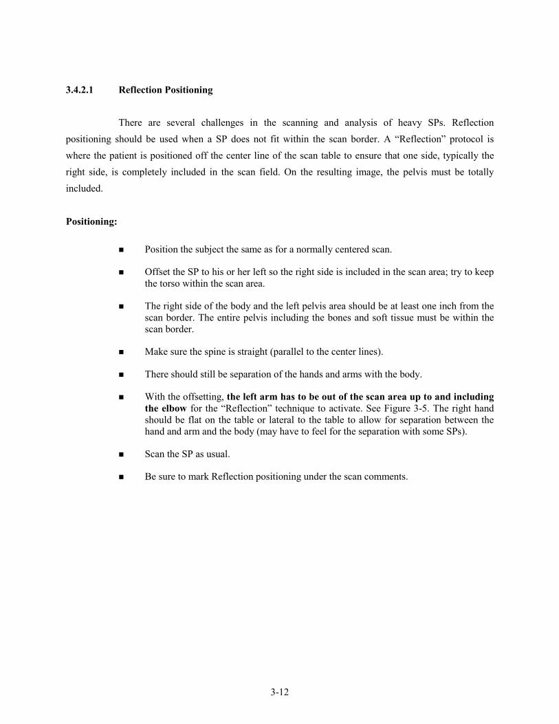
3.4.2.1 Reflection Positioning
There are several challenges in the scanning and analysis of heavy SPs. Reflection positioning should be used when a SP does not fit within the scan border. A “Reflection” protocol is where the patient is positioned off the center line of the scan table to ensure that one side, typically the right side, is completely included in the scan field. On the resulting image, the pelvis must be totally included.
Positioning:
Position the subject the same as for a normally centered scan.
Offset the SP to his or her left so the right side is included in the scan area; try to keep the torso within the scan area.
The right side of the body and the left pelvis area should be at least one inch from the scan border. The entire pelvis including the bones and soft tissue must be within the scan border.
Make sure the spine is straight (parallel to the center lines).
There should still be separation of the hands and arms with the body.
With the offsetting, the left arm has to be out of the scan area up to and including the elbow for the “Reflection” technique to activate. See Figure 3-5. The right hand should be flat on the table or lateral to the table to allow for separation between the hand and arm and the body (may have to feel for the separation with some SPs).
Scan the SP as usual.
Be sure to mark Reflection positioning under the scan comments.

3-13
Figure 3-5. Reflection positioning
3.5 Whole Body DXA Scan
Read and answer all (Shared) Safety Exclusion Questions in ISIS. You must complete up to the Data Capture screen in ISIS before performing an exam.
Click the “Perform Exam” icon or “Exam” in the top menu bar and select “Perform Exam” from its drop-down menu (Exhibit 3-5).

3-14
Exhibit 3-5. Selecting “Perform Exam”
3.5.1 Selecting an SP
In the “Patient Selections” screen, enter the SPID from the ISIS screen into the blank white field for Patient Name, or highlight the SPID from the list of IDs under the Patient Name column. Double check that you entered the correct SPID by asking for the SP’s birthday. Press “OK.” See Exhibit 3-6.

3-15
Exhibit 3-6. Patient selection screen
Enter your initials in the ‘Operator’ field and click “OK.” See Exhibit 3-7.
Exhibit 3-7. Operator field for initials

3-16
3.5.2 Selecting the Type of Scan
The next screen will display the types of scans to choose from. In the “Scan Selection” screen select the scan type by clicking on “Whole Body” with the mouse. The scan type is highlighted. See Exhibit 3-8. Click the “Next >>” button.
NOTE: If the SP was selected for the High Power Whole Body option, select HP Whole Body from the Scan Selection Screen.
Exhibit 3-8. Scan selection screen
The Whole Body Scan Parameters Screen will display. See Exhibit 3-9.
Verify the SPID under patient name and the scan type in the upper left corner.

3-17
Exhibit 3-9. Whole Body Scan Parameters screen
After the SP is positioned correctly for the whole body scan, check one more time to ensure there are no objects that will interfere with the movement of the table or the runner belt. Press “Start Scan” to begin the scan.
The machine will complete the scan.
Warning: If the Control Panel X-ray indicator fails to shut off within 10 seconds after the end of the scan, press the red Emergency Stop button immediately. Call the Hologic service representative before resuming operation.
3.5.3 Completing the Scan
The Scan window displays with the image appearing on the left side. The flashing “X-rays On” indicator at the top of the window continues until the scan stops. See Exhibit 3-10.
Make sure the SP’s arms are included in the scan on the first and last pass of the C-arm. The SP should remain still until the scan is complete. Allow the scan to complete.

3-18
Exhibit 3-10. Whole Body scan image
The analysis will be done later by the QC Reading Center.
Go to the ISIS screen and complete the DXA Data Entry screen.
Remove the Velcro strap from the SP’s feet and clean it with a Sani-wipe.
See Chapter 5 for a description of the information provided to the SPs from this test.
When the exam completes, an Exit/New Scan window box displays. See Exhibit 3-11. Click on “Exit Exam.”
Exhibit 3-11. Exit Exam/New Scan window box

3-19
3.6 DXA Scan Data
Analysis of the scans will be done at the QC Reading Center.
Exhibit 3-12 shows the data displayed after the regions of interest are selected and the analysis is completed.
This exhibit also displays the percent fat by region and for the total body. The percent total body fat for the hypothetical SP in the example is 23.6 percent.
Exhibit 3-12. Data displayed after analysis (1)

4-1
4. DATA ENTRY SCREENS
4.1 Shared Exclusion Questions
The Shared Exclusion Questions may be answered in several components in the MEC. If these questions have been answered in a previous component in the MEC, the questions and responses will be displayed in read-only format. If the SP is excluded from this exam based on his or her answers to the Shared Exclusion Questions in another component, the SP would be blocked from body composition by the Coordinator System and the SP would not be sent to this exam. The Component Status for body composition for this SP would be set to “Not Done” with a comment specific to the reason for exclusion (safety exclusion, physical limitation, etc.). NOTE: Not all of the Shared Exclusion Questions will exclude the SP from the DXA component. If you get a “Yes” response to certain Shared Exclusion Questions, the SP will not be excluded immediately. You must ask the remaining Shared Exclusion Questions and press the Next button before the SP is excluded. Other components will use the responses to these questions to determine eligibility. See Exhibit 4-1 for the Shared Exclusion Questions.
Exhibit 4-1. Shared Exclusion Questions

4-2
Do you have a pacemaker or automatic defibrillator?
SPs are not excluded from DXA due to a pacemaker or automatic defibrillator. If the response to this question is “Yes,” a series of exclusion messages will be shown to indicate that the SP is excluded from other examination components. See Exhibit 4-2.
Exhibit 4-2. Screenshot of exclusion for another component
Are you currently pregnant?
If the response to the question “Are you currently pregnant?” is “Yes” or “Don’t Know,” the SP will be excluded from DXA due to pregnancy status.
When the next button is pressed, a message will be displayed: “Excluded from DXA due to pregnancy status.” See Exhibit 4-3. Press OK to this message.

4-3
Exhibit 4-3. Exclusion from DXA due to pregnancy status
The Component Status will be set to “Not done” with the comment “SP pregnant.” If the SP is male or a female 8-17 years, the pregnancy questions will not be displayed. See Exhibit 4-4. (The question on self-reported pregnancy status for 12-to 17-year-old females will be asked in the physician’s exam).

4-4
Exhibit 4-4. Shared Exclusion questions without pregnancy question
In the past 7 days have you had any x-rays or scans that used contrast material such as dyes or barium?
If the response to the question “In the past 7 days have you had any x-rays or scans that used contrast material such as dyes or barium?” is “No,” continue with the next questions.
If the response to the question is “Yes,” the SP will be excluded from DXA.
Complete the remainder of the questions. When the Next button is pressed, a message will be displayed: “Excluded from DXA due to physical limitations.” See Exhibit 4-5. Click OK to this message.

4-5
Exhibit 4-5. Exclusion from DXA due to physical limitation
The DXA Component Status will be set to “Not Done” with the comment “physical limitation.” See Exhibit 4-6.
Exhibit 4-6. Exam status “Not Done” due to physical limitation

4-6
Do you have any amputations other than fingers and toes?
SPs are not excluded from the DXA exam based on an amputation. If the answer to “Do you have any amputations other than fingers and toes?” is “No,” the SP remains eligible for the exam.
If the response is “Yes,’ the question “Where is the amputation?” will be highlighted with response options of Right, Left, or Both. See Exhibit 4-7.
Exhibit 4-7. Response options for question “Where is the amputation?”
When all Shared Exclusion Questions are answered, the system will display a series of messages regarding the exclusions to other components based on the question.
If there are no exclusions based on the Shared Exclusion Questions, press the Next button. The system will advance to the Weight/Height data entry screen.
4.2 Weight/Height Entry Screen
After answering the Shared Exclusion questions, the next screen displayed will be the weight/height data entry screen. See Exhibit 4-8. Due to limitations of the DXA table, SPs may be excluded from DXA due to their height and/or weight. If the SP was in the anthropometry (BM) component or spirometry (SP) prior to this test, the weight and height will already be uploaded and

4-7
displayed on the ISIS screen, along with the component it transferred from (i.e., BM, SP). This information will be grayed out. See Exhibit 4-9. If the information is not displayed, you will need to measure the SP’s weight and height using the floor scale and stadiometer in the room. Enter these numbers into the white entry fields next to “Weight” and “Height.” See Exhibit 4-10. For instructions on measuring weight and height see Section 3.4.1. NOTE: If the SP’s weight is more the 450 lbs, or the height is greater than 6’5,” he or she will be excluded from the exam.
Exhibit 4-8. Weight/height entry screen
Exhibit 4-9. Weight/height information transferred from body measures

4-8
Exhibit 4-10. Entering the weight/height information into the screen
The system will use the height and weight measurements to calculate the body mass index (BMI) which will determine whether the SP needs the high power whole body scan or not. Females with a BMI > 32, and males with a BMI > 31 will be selected for this option. If the SP has been selected for the high power whole body scan a message will display in the Whole Body Data Capture Screen notifying the tech to select this option when performing the scan. See Section 4.4, Exhibit 4-16. SPs selected for the high power option may also be excluded if there is less than 6 inches of clearance between the SP and the C-arm.
4.3 Screening Questions
The screening questions will not flag an exclusion to this component but will be used in the analysis of this component. The questions should be read exactly as written. Read the entire question before accepting an answer. If the SP interrupts you before you have completed reading the question, say that you are required to read the entire question before accepting an answer. See Exhibit 4-11.

4-9
Exhibit 4-11. Screening questions
Have you removed all jewelry, eyeglasses, hair ornaments, and other objects from your hair and body?
Have you removed wallets, keys, and other objects from all of your pockets?
Do you have any artificial joints, pins, plates, metal suture material, or other types of metal objects in your body?
Are you using an insulin pump or have insulin lines now?
Do you have an ostomy, such as an ileostomy or colostomy?
Are you wearing a hearing aid now?

4-10
4.4 DXA Whole Body Data Capture Screen
Exhibit 4-12 is the ISIS DXA data capture screen.
Exhibit 4-12. DXA data capture (1)
This screen allows you to check whether or not the scan was completed.
There are no defaults on the screen when it is first displayed.
This screen has checkboxes to record any problems in getting a good quality scan. You can check one or more of the following problems.
-
-
-
-
-
-
SP movement during the exam;
Positioning problem;
Jewelry or other objects not removed;
Hands positioned along sides, not flat;
Too tall for table, feet out of scan;
Pillow used for head support;

4-11
-
-
-
-
Equipment failure;
Reflection used during the whole body scan;
Less than 6 inches of clearance (enabled for SPs selected for high power option); or
Other – specify.
If the scan is completed, select “Yes.” See Exhibit 4-13.
Exhibit 4-13. DXA data capture (2)
The system will automatically enter the Archive File name.
The Archive number is D for DXA, 042611 for April 26, 2011, and 00 for the first file to be archived. The file extension is .ARC.
If the scan is completed successfully, the Component Status will be “Complete.”
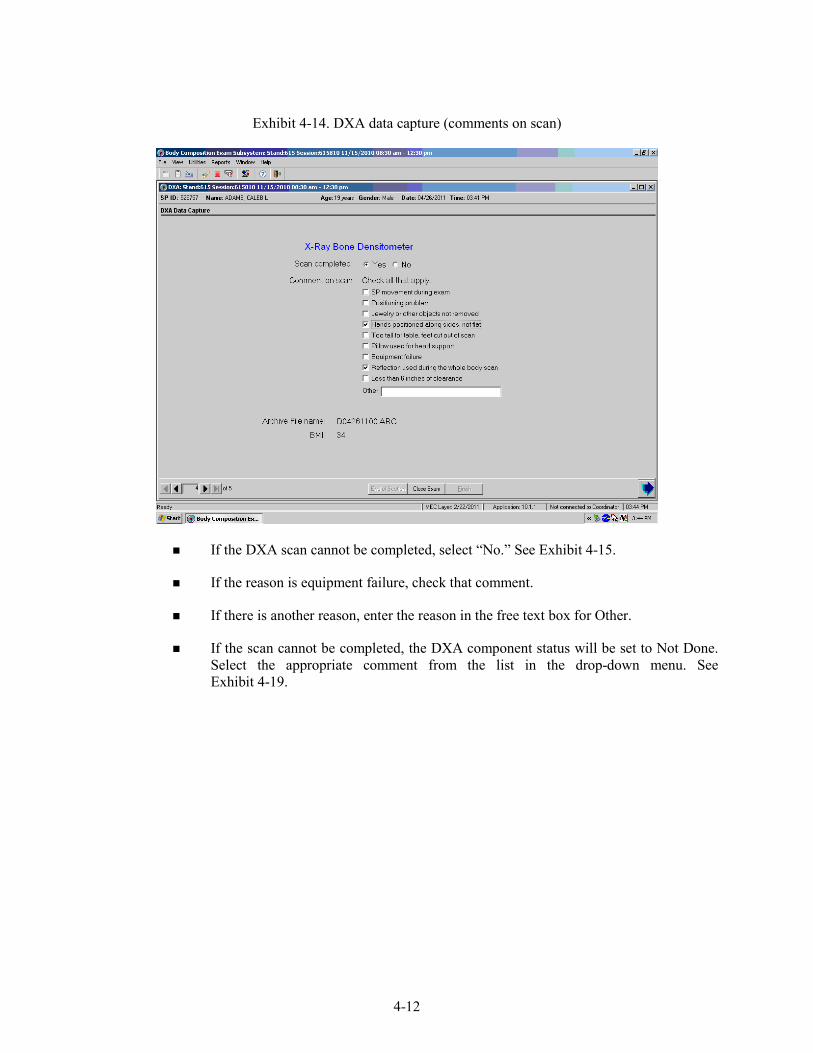
During and immediately after the scan, check the scan for quality. See Exhibit 4-14.
Check all comments that apply.
4-12
Exhibit 4-14. DXA data capture (comments on scan)
If the DXA scan cannot be completed, select “No.” See Exhibit 4-15.
If the reason is equipment failure, check that comment.
If there is another reason, enter the reason in the free text box for Other.
If the scan cannot be completed, the DXA component status will be set to Not Done. Select the appropriate comment from the list in the drop-down menu. See Exhibit 4-19.

4-13
Exhibit 4-15. DXA data capture (scan not completed)
If the SP has been selected for the High Power Whole Body scan a message will display in the Whole Body Data Capture Screen. See Exhibit 4-16.
Exhibit 4-16. HP message box

4-14
If the SP has been selected for the High Power Whole Body scan and the HP option was not used, an error message will display. See Exhibit 4-17.
Exhibit 4-17. HP error message
4.5 DXA Component Status
The completion status for the DXA component is either of the following:
Complete 8 through 59 years Whole body scan
Not Done 8 through 59 years Whole body scan interrupted or not completed
If a comment is not selected when the status is “Not Done,” a message will be displayed: “Please select comments.” See Exhibit 4-18.
Click OK to this message and select the appropriate comment.
Press the Finish button to end the exam.

4-15
Exhibit 4-18. DXA component status (required comments)
If the component status is “Not Done,” the system will require a comment to be selected from the drop-down menu. See Exhibit 4-19.

4-16
Exhibit 4-19. DXA component status
The comments in the drop-down box are the following:
-
-
-
-
-
-
Data effect;
Equipment failure;
Error (technician/software/supplies);
Inability to lie still;
Interrupted; and
Language Barrier;
Other comments in the drop-down box that are not shown in Exhibit 4-19 are the following:
-
-
-
Awaiting pregnancy result;
Communication problem;
No time;

4-17
-
-
-
-
-
-
-
-
-
-
-
-
-
Other – specify;
Pain or discomfort;
Physical limitation ;
Proxy, no information;
Safety exclusion;
SP ill/emergency;
SP moved during the procedure;
SP pregnant;
SP refusal;
SP unable to comply;
Urine not collected;
Weight limitation on equipment; and
Exceeds height limitation.
4.6 Session PickUp List
The Session Preview box can be accessed from the Toolbar under Reports.
Go to Reports, select Session preview from the menu.
A list of current sessions will be displayed. See Exhibit 4-20.

4-18
Exhibit 4-20. Session preview
4.7 Session Preview Report
The Session Preview Report can be accessed from the Toolbar under Reports.
Go to Reports and select Session Preview from the menu.
The list of SPs in the current session is displayed. The SP identification number, the type (primary, guest, replicate), name, age, gender, special considerations, and comments are displayed (Exhibit 4-21).

4-19
Exhibit 4-21. Session Preview Report
4.8 Room Log
The Room Log can be accessed from the Toolbar under Reports.
Go to Reports and select Room Log from the menu.
A list of the SPs eligible for this component is displayed.
The SP ID, name, sex, age, SP status, and component status are displayed. See Exhibit 4-22.

4-20
Exhibit 4-22. Room log for body composition
4.9 Close Exam
Any exam may be terminated at any point during the exam (SP becomes ill, changes his or her mind about completing the test). See Exhibit 4-23.
The “Close Exam” button is used to end the exam abruptly without going through the remaining screens.
Choose a comment and click on Close to end the exam.

4-21
Exhibit 4-23. Close exam

5-1
5. REFERRALS AND REPORT OF FINDINGS
5.1 Observation Referrals
Observation referrals are nonemergency situations that may arise in any of the examination rooms in the MEC. Technologists may send an observation referral to the MEC physician if they notice any condition that may be abnormal or that may warrant further assessment. This type of referral may be sent at any time from any of the exam rooms. The referral may or may not have anything to do with the current exam being performed.
Once a technologist sends a referral to the physician, the ISIS system will flag the referral for the SP in the Physician Referral Review box. The SP will not be checked out of the MEC until the physician has reviewed this referral. The physician will make a decision whether further action is warranted and a physician referral to the SP’s health care provider may be given to the SP.
Observation referrals can be sent during the exam or after the exam has been closed;
Under “Utilities,” select “Observations.” If an exam is already opened, the Observation referral box for that SP will be displayed. See Exhibit 5-1; and
If the exam has been closed, select “Observation” from the “Utilities” menu. A pick list with the names of the SPs in the current session will be displayed. This list is only displayed if “Utilities/Observations” is selected when an exam is not open. See Exhibit 5-2.
Exhibit 5-1. Menu to select observation referral

5-2
Exhibit 5-2. Pick list of SPs in current session
Select the name of the SP for whom an observation referral should be sent. Click OK.
Exhibit 5-3. Observation referral in body composition
Type in the message you would like to send to the physician. When you are finished, click OK. See Exhibit 5-4.

5-3
Exhibit 5-4. Observation referral from other components in physician’s referral review box
Exhibit 5-4 above shows the referral as it appears in the Physician’s Referral Review box. The message typed in the Observation Referral box in body composition appears in this box in the Physician Referral Review;
The physician will review this referral and make a decision about further action if warranted; and
The SP cannot be checked out of the MEC until the physician has reviewed this referral.
5.2 Report of Findings for Body Composition
Each SP will be given a report of the results or findings for the exams performed. The Report of Findings for the DXA whole body exam will include a report on the total percent body fat. The heading for the report will be “Body Composition.”
Results will be included in the final Report of Findings sent from NCHS. Participants who are 8 through 59 years of age will receive a Report of Findings on their whole body. Participants less than 8 years and greater than 59 years will not have a whole body scan so there will be no results on this scan for this age group.

5-4
The variables reported for the whole body scan will be total percent body fat. A statement is included informing participants that we currently do not know what percent body fat is considered a healthy range for the public. Participants are told that researchers are working to define this range and participants are advised to discuss the results with their health care provider to find out more about what the results mean on an individual basis.
5.2.1 Sample Preliminary Report of Findings
Refer to Exhibit 5-5 for a sample of preliminary reports of findings.
Exhibit 5-5. Sample Report of Findings for body composition
National Health and Nutrition Examination Survey Report of Findings DXA 2011
Body Composition
The whole body scan provides information on your percent body fat.
The body composition exam results showed that your total body fat is ____%.
We do not know exactly what percent body fat is considered healthy for your age and gender. Researchers are working to define the healthy ranges for the public. You may want to discuss this result and your body measurement findings (page 1) with your doctor to find out what they mean for you. Too
much body fat can increase a person’s risk of getting diabetes or heart disease.

6-1
6. QUALITY CONTROL
6.1 Equipment and Room Set-Up Checks
The equipment, room supplies, and room set-up need to be checked on a regular basis. Some checks are completed daily and others need only be completed on a weekly basis or at the beginning of each stand. These checks include calibration checks, maintenance inspection of equipment and supplies, and preparation of the room and equipment for the session exams.
Each time you log onto the application, the system will remind you to do quality control (QC) checks if the checks have not been completed for that time period. The checks are to be completed daily, weekly, 3 times a week, and/or every stand. If you do not have time to do the checks when you log on, you can bypass this message and complete the checks at a later time. However, this message will be displayed each time you log on until you have completed the checks for that time period. Once you have completed the checks and entered this in the system, the message box with the reminder will not be displayed again until the appropriate time period has passed.
An exception to the above is the QC check with the Hologic Anthropomorphic Spine Phantom. This spine phantom must be scanned daily to confirm the calibration of the densitometer before the densitometer will allow scans to be completed. If an attempt is made to perform a scan before the daily QC is completed, an error message will be displayed. Press Enter at this message and complete the spine phantom calibration.
The daily, 3 times/week, weekly, and once-a-stand checks are listed in the following sections.
6.1.1 Daily
1 spine phantom (Hologic Anthropomorphic Spine Phantom – HASP).
Check that table scan area is clear of articles that might interfere with table movement.
Check runner area of table to confirm the area is clear of articles that might interfere with table movement.

6-2
6.1.2 Three Times Per Week (1st, 3rd, and 5th days of workweek)
Complete all daily checks.
- 1 Spine Phantom
- 1 Slim-line Whole Body Phantom
6.1.3 Weekly
Complete all daily checks.
- 1 Spine Phantom
Complete the “3 times weekly” scans.
- 1 Slim-line Whole Body Phantom
1 Radiographic Uniformity.
1 Step Phantom.
6.1.4 Start of Stand
Check that the locking pins have been removed before attempting to complete any scans.
1 Spine Phantom.
1 Step Phantom.
1 Radiographic Uniformity.
5 Slim-line Whole Body Phantom.

6-3
DXA
- 10 circulating spine phantom (HSP-Q-96) Only at the first stand of the year for each MEC
- 10 circulating block phantom (NH #1) Only at the first stand of the year for each MEC
- 5 Hologic Whole Body Phantom (HWBP) (WB Phantom #008) Only at the first stand of the year for each MEC
6.1.5 End of Stand
Clean DXA table with a very dilute solution of Ivory dishwashing detergent.
6.2 Procedures for Completing QC Scans
6.2.1 Hologic Anthropomorphic Spine Phantom (HASP)
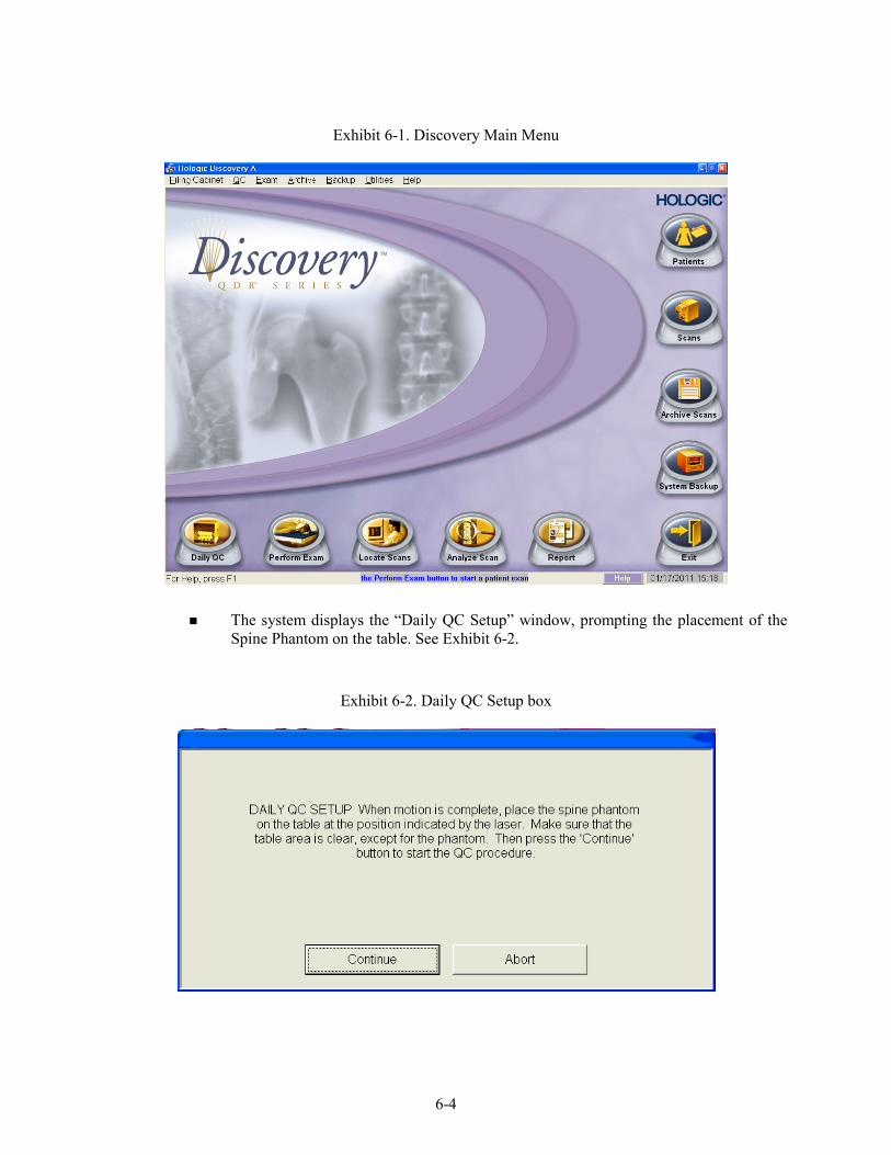
In the Discovery QDR main menu (Exhibit 6-1), click on the Daily QC button.
Alternatively, “Daily QC” can be selected from the QC pull-down menu in the main menu to start the daily QC procedure.
6-4
Exhibit 6-1. Discovery Main Menu
The system displays the “Daily QC Setup” window, prompting the placement of the Spine Phantom on the table. See Exhibit 6-2.
Exhibit 6-2. Daily QC Setup box

6-5
When the table motion is complete, place the spine phantom on the table with the registration mark (see “A” in Figure 6-1) to the left foot end.
Position the phantom parallel to the back of the table.
Align the laser crosshair (see “B” in Figure 6-2) with the registration mark.
Once the spine is properly positioned, click the “Continue” button. The System starts performing an automatic test.
Figure 6-1. Spine phantom registration mark

6-6
Figure 6-2. Spine phantom and laser crosshair position
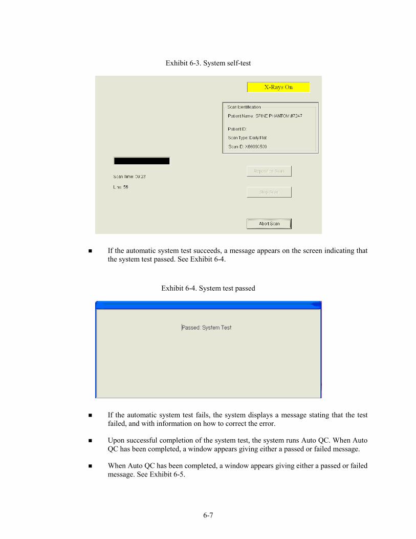
The Discovery A system automatically performs a system test to verify proper operation of its X-ray subsystem prior to scanning the spine phantom. The following screen, Exhibit 6-3, is displayed during the system test.
6-7
Exhibit 6-3. System self-test
If the automatic system test succeeds, a message appears on the screen indicating that the system test passed. See Exhibit 6-4.
Exhibit 6-4. System test passed
If the automatic system test fails, the system displays a message stating that the test failed, and with information on how to correct the error.
Upon successful completion of the system test, the system runs Auto QC. When Auto QC has been completed, a window appears giving either a passed or failed message.
When Auto QC has been completed, a window appears giving either a passed or failed message. See Exhibit 6-5.

6-8
Exhibit 6-5. Auto QC passed
6.2.1.1 Checking BMD and BMC
To review the QC plot, click on the PLOT button from the QC Results window for a passed Auto QC. (See Exhibit 6-4 shown earlier). The QC Plot window appears.
Check the BMD graph for the circle for that day’s scan (at far right side of graph). See Exhibit 6-6.
The circle should be within the two dotted lines.
The CV for BMD should be at or below 0.60 percent.

6-9
Exhibit 6-6. Spine Phantom QC – plot for BMD
If the circle is not within the dotted lines or the CV is greater than 0.60 percent, see directions in Section 6.2.1.2.
To check the BMC select the BMC tab at the top of the screen by clicking on it.
Check the BMC graph for the circle for that day’s scan (at the far right side of the graph). See Exhibit 6-7.

6-10
Exhibit 6-7. Spine Phantom QC – plot for BMC
The circle should be within the two dotted lines.
The CV for BMC should be at or below 0.80 percent.
If the circle is not within the dotted lines or the CV for BMC is greater than 0.80 percent, see directions in Section 6.2.1.2.
If the circle is within the dotted lines and the CV for BMC is at or below 0.80 percent, press BACK to return to the Auto QC passed window or CLOSE to return to the system main menu.
Read the messages on the Hologic computer screen. (If the step phantom hasn’t been scanned in the past week, a message will be displayed stating that it should be scanned following the spine phantom scan.) See Exhibit 6-8.
6.2.1.2 Auto QC Failure
If Auto QC fails, the message is “Daily QC failed” and a series of steps is provided. The QC Results Window contains four buttons: Details, Review Analysis, Plot and OK. Clicking Details provides additional information about the QC failure.

6-11
Click OK to return to the system main menu so Daily QC can be re-run.
If after two attempts, the Daily QC continues to fail, report this to the chief technologist AND the MEC manager. This information must be reported to Hologic.
The MEC manager is responsible for all calls, but may delegate this responsibility to the chief technologist at his or her discretion.
Record this call on the “Equipment Problem Call Log.” Stop all scans until further notice from the Hologic technician.
6.2.2 Step Phantom
Select QC from the top menu bar in the QDR Main Menu (See Exhibit 6-1 shown earlier.) and select Step Phantom from the drop-down menu. A message box will prompt the setup of the Step Phantom QC. See Exhibit 6-8.
Exhibit 6-8. Step Phantom Setup window

6-12
When the table motion is complete, place the body composition phantom lengthwise on the table with the thinnest step to your right as you face the table.
Center the long axis of the phantom to the long axis of the laser light.
Center the middle of the crosshair 3/4 of an inch from the right side of the thinnest step.
Press “Continue” to start the scan.
The step phantom will display in the black box in the left center of the screen. See Exhibit 6-9.
Exhibit 6-9. Step Phantom scan
At the conclusion of the scan, the step phantom is automatically analyzed and the data are stored in a separate file in the system.
The system will display a message “The step phantom evaluation was completed successfully.” See Exhibit 6-10.

6-13
Exhibit 6-10. Step Phantom Evaluation completed successfully
Press “OK.”
The system will display a message “The step phantom scan for body composition calibration has been completed.” When the table has finished moving, press the “Continue” button to continue. See Exhibit 6-11. (If this window message continues to appear, after pressing continue, press “abort” to return to the Discovery QDR main menu.

6-14
Exhibit 6-11. Step Phantom QC completed, press “Continue”
6.2.3 Radiographic Uniformity Test
After completion of the step phantom scan, an automatic prompt should come up for the Radiographic Uniformity Test. The system will analyze the scan and give you the Standard Deviations (SD) values for the High Air and the Low Air. Record these values in ISIS and on the QC scan log sheets. If the prompt does not come up, then follow the instructions below to select the test manually.
Select “Perform Exam” from the QDR Main Menu. See Figure 6-1.
Choose or highlight “Radiographic Uniformity” from the patient list. See Exhibit 6-12.

6-15
Exhibit 6-12. Selecting Radiographic Uniformity from patient list
Radiographic Uniformity will be highlighted, (not Slim-Line WB Phantom)
Click “OK.”
Type in initials in the white text box next to the word Operator (see Exhibit 6-13) and Click “OK.”

6-16
Exhibit 6-13. Operator box for initials
Select “Whole Body” in the Scan Selection Screen. Exhibit 6-14. Click “Next>>.”
Will say Radiographic Uniformity here, not Patient #.

6-17
Exhibit 6-14. Selecting Whole Body in the select scan type screen
The Scan Parameters Screen is displayed. Exhibit 6-15.
Exhibit 6-15. Radiographic Uniformity scan parameters screen
Will say Radiographic Uniformity here.
Will say Radiographic Uniformity here, not Patient #.

6-18
Clear entire table of any objects and click “Start Scan.”
The Radiographic Uniformity will display a black box in the left center of the screen. See Exhibit 6-16.
Exhibit 6-16. Radiographic Uniformity test
A program will automatically analyze the airscan.
6.2.3.1 Finding the Global Standard Deviation (SD) for the Radiographic Uniformity Test (Airscan)
In the Discovery QDR main menu, select “Utilities” then “Service Utilities” from the drop-down box and then “Table Top Radiographic Uniformity” from the second drop-down box.
Select or highlight the Radiographic Uniformity with the correct scan date (date of QC Test) see Exhibit 6-17.

6-19
Exhibit 6-17. Selecting Radiographic Uniformity for SD results
There are two SDs, a High Air and a Low Air. See Exhibit 6-18 and 6-19. Select from the tabs at the top of the window. Enter both numbers in ISIS.

6-20
Exhibit 6-18. High Air global stats SD
Exhibit 6-19. Low Air global stats SD

6-21
6.2.3.2 Procedure if Standard Deviation (SD) is Greater Than 2.0
Report this to the chief technologist AND the MEC manager.
**Chief Technologist and MEC Manager:
Check the results of the Radiographic Uniformity Test and confirm that the scan procedure was completed correctly.
Perform a second scan and note the results. If the Standard Deviation is still >2.0, call the home office to report the results of the test and contact Hologic (See laminated instruction sheets in the DXA room for the names and numbers of the people to contact).
Record this call on the “Equipment Problem Call Log.” STOP all scans until further notice from Hologic.
6.2.4 Slim-line Whole Body Phantom
Lift the phantom components on and off the table one at a time.
Press the center table button to center the laser. Use the laser to assist in centering the phantom on the table.
Place the bottom layer (base) on the scanner table. (The bottom layer consists of a thin, gray PVC sheet bonded to the largest high density polyethylene (HDPE) piece.) Orient the sheet with the gray PVC on the bottom and the end marked “Head End” at the head end of the table.
Place the second large white plastic piece (with beveled edges) on top of the base, using the locating pins as a guide if necessary. The second piece should be placed such that the beveled edge is in contact with the base layer, like a pyramid.
Place the medium-sized white plastic piece on the phantom.
Add the second medium-sized white plastic piece (with the beveled edges), again forming a pyramid.
Place the smallest white plastic piece on the phantom.
Add on the smallest white plastic piece (with the beveled edges) to complete the pyramid.
Secure the stack with the two locating pins.

6-22
The final assembly will form a pyramid. (See Figure 6-3.) It is important that the phantom is placed in exactly the same configuration every time it is scanned.
Figure 6-3. Slim-line whole body phantom fully assembled
6.2.4.1 Phantom Positioning
The phantom should be centered top to bottom and side to side on the table. Use the laser to assist in centering the phantom.
6.2.4.2 Scanning the Slim-Line Whole Body Phantom (Days 1, 3, 5)
Confirm that the phantom is centered, parallel with the long axis of the table, and is correctly oriented with respect to the head of the table.
Confirm all artifacts are removed from the scanner table surface.
Select “Perform Exam” from the Discovery QDR Main Menu. See Figure 6-1 shown earlier.
Choose Slim-Line WB Phantom #XXXX (XXXX is 1013 on MEC 1, 1021 on MEC 2, or 1022 on MEC 3) from the list or begin typing Slim… in the white text box next to Patient Name and the name will highlight in the list. See Exhibit 6-20. Click “OK.”

6-23
Exhibit 6-20. Selecting Slim-Line WB Phantom scan
Type in initials in the white text box next to the word Operator (see Exhibit 6-21) and Click “OK.”
Exhibit 6-21. Operator box for initials

6-24
CONFIRM that “Slim-Line WB Phantom #XXXX” is in the Patient Field.
Select “Whole Body” in the Scan Selection Screen. Exhibit 6-22. Click “Next>>.”
Exhibit 6-22. Selecting Whole Body in the select scan type screen
The Scan Parameters Screen is displayed. Click “Start Scan.” Exhibit 6-23.

6-25
Exhibit 6-23. Slim-Line scan parameters screen
The machine will scan the phantom.
As the scan is completing, carefully inspect the image to ensure that the phantom was centered, parallel with the long axis of the scanner table and the phantom’s head appears at the top of the image.
If the scan is not satisfactory, reposition the phantom again, carefully following the instructions above.
6.2.4.3 Scanning the Slim-line Whole Body Phantom for Start of Stand
Confirm that the phantom is centered, parallel with the long axis of the table, and is correctly oriented with respect to the head of the table.
Confirm all artifacts are removed from the scanner table surface.
Follow procedures from Section 6.2.4.2 for scanning the first Slim-line Whole Body Phantom scan.
If the scan is satisfactory, slide the phantom down the table and then recenter. Scan 4 more times with repositioning between each scan, checking that each scan is satisfactory.
NOTE: Autoscan cannot be used for the Slim-line Whole Body Phantom.

6-26
6.2.5 Circulating HASP (HSP Q-96)
NOTE: This phantom is a different phantom from the one used for daily scans. Do not use the regular spine phantom that is used for daily QC scans.
Center the table. When the table motion is complete, position the Hologic Circulating Spine Phantom on the table at the position indicated by the laser cross.
The positioning star should be pointing to the foot of the table (your left as you face the table).
The laser cross should be centered on the positioning star.
The laser line should be centered on the line between the numbers 9 and 6.
On the Discovery QDR main menu screen, click “Utilities” at the top of the screen.
From the drop-down menu, select “Service Utilities” and then “Auto Scan” from the second drop-down menu.
Choose Hologic Spine Phantom Q-96 from the list or begin typing Hologic Spine… in the white text box next to Patient Name and the name will highlight in the list. Click “OK.”
Type in initials in the white text box next to the word Operator. Click “OK.”
CONFIRM that “Hologic Spine Phantom Q-96” is in the patient field.
Select “AP Lumbar Spine” in the Scan Selection screen. Figure 6-24.
In white text box to the left of “Number of times to run scan,” type the number 10. See Figure 6-24.
Click “Next >>.”
The Scan Parameters Screen is displayed. Click “Start Scan.”
The machine will scan the phantom.
A total of 10 scans should have been completed.

6-27
6.2.6 Circulating Block Phantom (Hologic Block Phantom NH #1)
Center the table. When the table motion is complete, position the Hologic circulating spine phantom on the table at the position indicated by the laser cross.
The positioning star should be pointing to the foot of the table.
The laser cross should be centered on the positioning star.
The laser line should be positioned between the numbers 1 and 2.
On the Discovery QDR main menu screen, click “Utilities” at the top of the screen.
From the drop-down menu, select “Service Utilities” and then “Auto Scan” from the second drop-down menu.
Choose Hologic Block Phantom NH #1 from the list or begin typing Hologic Block… in the white text box next to Patient Name and the name will highlight in the list. Click “OK.”
Type in initials in the white text box next to the word Operator. Click “OK.”
CONFIRM that “Hologic Block Phantom NH #1” is in the Patient Field.
Select “AP Lumbar Spine” in the Scan Selection Screen.
In white text box to the left of “Number of times to run scan,” type the number 10.
Click “Next >>.”
The Scan Parameters Screen is displayed. Click “Start Scan.”
The machine will scan the phantom.
A total of 10 scans should have been completed.
6.2.7 Hologic Whole Body Phantom #008
6.2.7.1 Phantom Assembly
Lift the phantom components on and off the table one at a time.
Refer to the diagram to assist in positioning the phantom correctly.
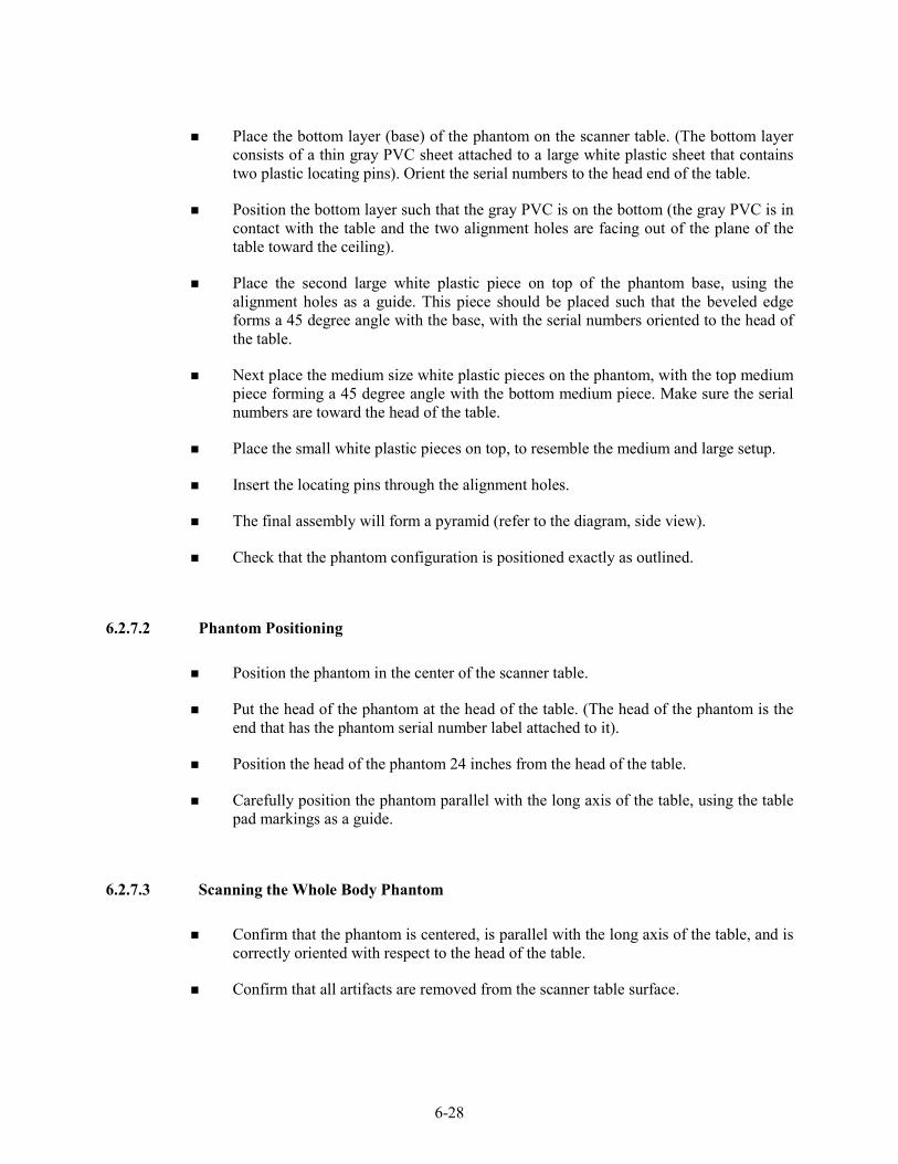
6-28
Place the bottom layer (base) of the phantom on the scanner table. (The bottom layer consists of a thin gray PVC sheet attached to a large white plastic sheet that contains two plastic locating pins). Orient the serial numbers to the head end of the table.
Position the bottom layer such that the gray PVC is on the bottom (the gray PVC is in contact with the table and the two alignment holes are facing out of the plane of the table toward the ceiling).
Place the second large white plastic piece on top of the phantom base, using the alignment holes as a guide. This piece should be placed such that the beveled edge forms a 45 degree angle with the base, with the serial numbers oriented to the head of the table.
Next place the medium size white plastic pieces on the phantom, with the top medium piece forming a 45 degree angle with the bottom medium piece. Make sure the serial numbers are toward the head of the table.
Place the small white plastic pieces on top, to resemble the medium and large setup.
Insert the locating pins through the alignment holes.
The final assembly will form a pyramid (refer to the diagram, side view).
Check that the phantom configuration is positioned exactly as outlined.
6.2.7.2 Phantom Positioning
Position the phantom in the center of the scanner table.
Put the head of the phantom at the head of the table. (The head of the phantom is the end that has the phantom serial number label attached to it).
Position the head of the phantom 24 inches from the head of the table.
Carefully position the phantom parallel with the long axis of the table, using the table pad markings as a guide.
6.2.7.3 Scanning the Whole Body Phantom
Confirm that the phantom is centered, is parallel with the long axis of the table, and is correctly oriented with respect to the head of the table.
Confirm that all artifacts are removed from the scanner table surface.

6-29
On the Discovery QDR main menu screen, click “Perform Exam” at the bottom of the screen.
Choose WB Phantom #008 (008 is the serial number of the Whole Body Phantom) from the list or begin typing WB… in the white text box next to patient name and the name will highlight in the list. Click “OK.”
Type in initials in the white text box next to the word Operator. Click “OK.”
CONFIRM that “WB Phantom #008” is in the patient field.
Select “Whole Body” in the Select Scan Type box. Click “Next >>.”
The Scan Parameters Screen is displayed. Click “Start Scan.”
The machine will scan the phantom (Figures 6-4 and 6-5).
Figure 6-4. Layout of whole body phantom – top view

6-30
Figure 6-5. Layout of whole body phantom – side view
Carefully inspect the scan image to ensure that the phantom was centered, parallel with the long axis of the scanner table and the phantom’s head appears at the top of the image.
If the scan image was not satisfactory, click abort and reposition the phantom again carefully following the instructions above.
A total of 10 scans should be completed.
6.3 Using Auto Scan at Start of Stand
The feature Auto Scan may be used for scanning multiple phantom scans at the start of stand. It can be used for:
- Circulating Spine Phantom (HSP Q96) – 10 scans
- Circulating Block Phantom (NHANES Block #1) – 10 scans
NOTE: It cannot be used for the Hologic Whole Body Phantom (WB #008) or the Slim-line Whole Body Phantom (Slim-line WB Phantom #XXXX).
To use the Auto Scan feature, click “Utilities” at the top of the screen in the Discovery QDR Main Menu.
From the drop-down menu, select “Service Utilities” and then “Auto Scan” from the second drop-down menu.
Select or highlight the appropriate phantom from list. Click “OK.”
Type in initials in the white text box next to the word Operator and Click “OK.”
CONFIRM that the correct phantom is in the patient field.
Select the Whole Body in the Scan Selection Screen. See Exhibit 6-24.
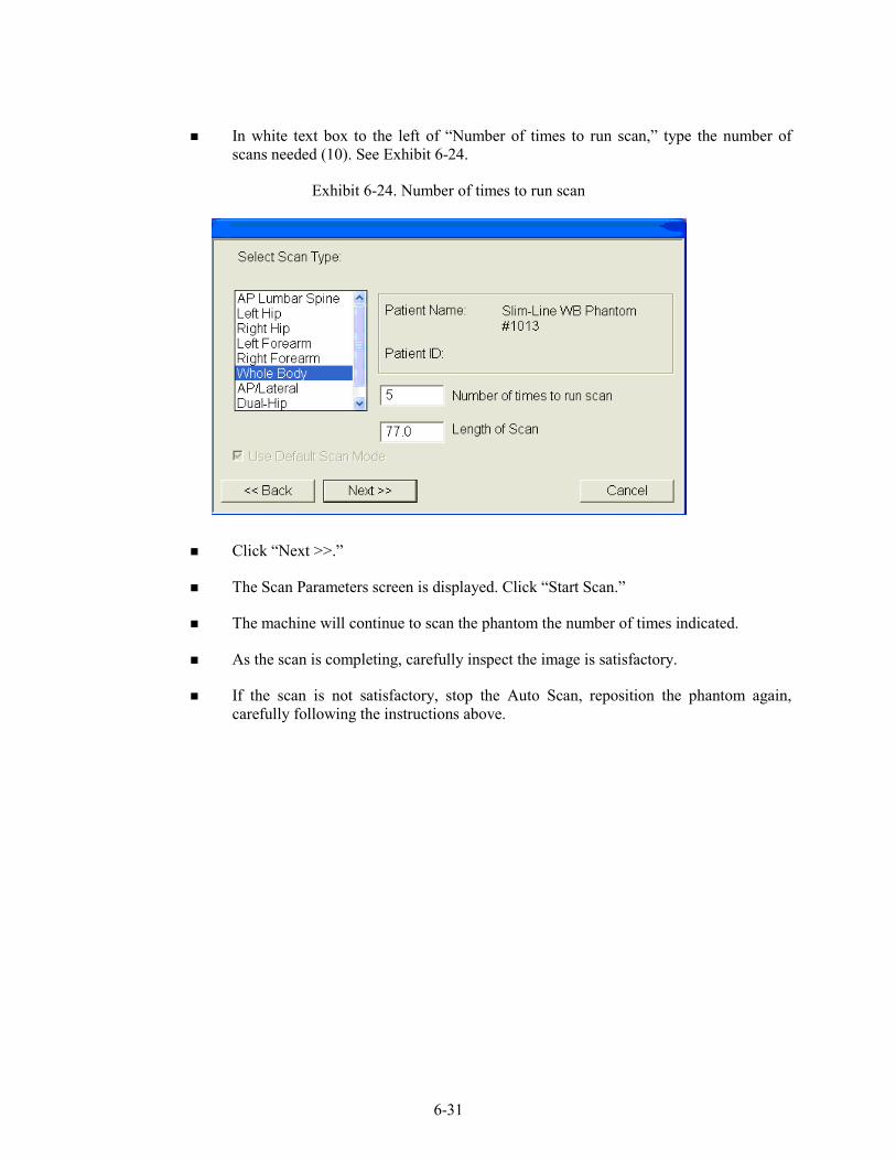
6-31
In white text box to the left of “Number of times to run scan,” type the number of scans needed (10). See Exhibit 6-24.
Exhibit 6-24. Number of times to run scan
Click “Next >>.”
The Scan Parameters screen is displayed. Click “Start Scan.”
The machine will continue to scan the phantom the number of times indicated.
As the scan is completing, carefully inspect the image is satisfactory.
If the scan is not satisfactory, stop the Auto Scan, reposition the phantom again, carefully following the instructions above.

6-32
6.4 QC Scan Checklists
The QC Scan checklists were developed to ensure that all QC Scans are completed as outlined in the protocol. There are two forms: one is used for all daily, 3 times/week, and weekly QC scans; the other is used for all Start of Stand QC scans. See Appendixes E and F for sample forms.
6.4.1 Instructions for Completing Weekly QC Scan Checklist
The checklist should be filled out on each day of the workweek by the health technologist who is responsible for completing the QC scans that week.
As scans are completed each day, check the appropriate boxes.
During the week, keep the checklist in the Body Composition Procedures manual. At the end of each week, file the completed form in the “Weekly QC Scans Checklist” section in the back of the manual, behind the previous week’s form.
6.4.2 Instructions for Completing Start of Stand QC Scan Checklist
The checklist should be filled out at the start of the stand by the health technologist who is responsible for completing the start of stand scans.
As each scan is completed, check the appropriate box.
File the completed form in the “Start of Stand QC Scans Checklist” section in the back of the manual, behind the form from the previous stand.

6-33
6.4.3 Instructions for Accessing Blank QC Checklist Forms
Blank QC Checklists for all DXA scans are stored electronically in the “Blank Forms” folder on the ISIS computer in the MEC. Use the following steps to access the forms.
Open Microsoft Word. (Click on the icon on the desktop).
From the “File” menu, select “Open.”
Select the “MECStaff” directory.
Select “Blank Forms.”
Select the appropriate form:
- DXA_QC1 Daily, 3x/Week, and Weekly QC checklist
- DXA_QC2 Start of stand checklist
Open the document by double clicking on it or by selecting it and clicking “Open.”
From the ‘File’ menu, select “Print.”
6.5 Data Entry Screens for QC on Equipment
When you log onto the application before the quality control checks are performed, the system displays a message: “One or more of your QC checks have not been performed.” See Exhibit 6-25.
Click OK to this message.
Exhibit 6-25. Quality Control reminder message box
When you want to complete the QC checks, select “Utilities.” Then select “Quality Control” from the menu. See Exhibit 6-26.

6-34
Exhibit 6-26. Utilities menu to select quality control
Clicking on the QC icon from the Toolbar can also access the QC screens.
When QC is selected from the Utilities menu, the User ID entry box will be displayed. See Exhibit 6-27.
Exhibit 6-27. Quality Control log-on
Each technologist will have a personal ID. This ID will be used to identify the person who completed the QC checks for this time period.
Enter your User ID and click OK.
If you do not want to do the QC checks at this time, click Cancel.

6-35
6.5.1 QC Daily Checks
The Daily QC check data entry screen is shown in Exhibit 6-28.
Exhibit 6-28. Quality Control daily checks
On the QC screens, check “Done” for the listed items when that item has been completed.
You are not required to enter anything in the “Result” or “Comment” fields unless there is a problem.
The “Result” field is used to enter values for selected QC items if required.
The “Comments” field is used to enter information about problems encountered with the QC item check.
Use the scroll bar to move to the remaining items.
When you are finished with the daily item checks, click OK to close the QC box.
6.5.2 QC Weekly Checks
The QC Weekly Checks Data Entry screen is shown in Exhibit 6-29.
Complete all the daily checks.

6-36
Exhibit 6-29. Quality Control weekly checks
Check “Done” for each item on the weekly checks when complete.
Use the Scroll down bar on the right of the screen to get to the remaining items.
If you notice a problem with any of the items on the checklist, make a note of this in the comment box and report it to chief tech AND the MEC manager.
6.5.3 QC Start of Stand Checks
The QC Start of Stand Checks data entry screens are shown in Exhibits 6-30 and 6-31.

6-37
Exhibit 6-30. Quality Control start of stand checks (1)

6-38
Exhibit 6-31. Quality Control start of stand checks (2)
Complete all “Start of Stand” checks.
“Start of Stand” checks include all daily and weekly checks.
When the “Start of Stand” checks are complete, click OK to close the QC checks.
Complete the remaining “Start of Stand” checks.
When you have completed all checks, click OK to close the QC box.
6.5.4 QC Yearly Checks
The yearly QC data entry screen is shown in Exhibit 6-32.
Complete all the yearly checks at the beginning of the year for each MEC.
When the “Yearly” checks are complete, click OK to close the QC checks.
Complete the remaining “Start of Stand” checks.
When you have completed all checks, click OK to close the QC box.

6-39
Exhibit 6-32. Quality Control yearly checks

6-40
6.5.5 QC End of Stand Checks
Clean the DXA table by wiping it down with a clean damp cloth and liquid Ivory™ soap. Do not complete this item until all exams for the stand have been completed to ensure that no scans are done on a damp table. See Exhibit 6-33.
Exhibit 6-33. Quality Control end of stand checks
If the table needs to be cleaned more often, follow the procedures for end of stand cleaning at the end of the examination week. This will allow the table to dry prior to the beginning of the next week.
6.5.6 Incomplete QC Checks
If you do not check that all items are complete, the system will display this message: “Not all the QC items were done. Do you wish to exit?” See Exhibit 6-34.

6-41
Exhibit 6-34. Quality Control incomplete entry
If you want to complete the items before exiting, click “No” to this message and complete the items.
If you wish to exit without completing all the QC checks, click “Yes” to this message.
If all QC items were not complete, the system will remind you each time you log on that the QC checks are not complete.

APPENDIX A
BODY COMPOSITION (DXA) SCRIPTS

A-1
APPENDIX A
BODY COMPOSITION (DXA) SCRIPTS
Introduction to Component (Suggested Script)
English Spanish
In this room, we are going to be doing an exam that will tell us how much body fat you have. I will explain in more detail as I do the exam. Please have a seat up here on the table and get as comfortable as possible. I am going to ask you a few questions before I start the exam.
En esta habitación, le haremos un examen que nos dirá cuánta grasa corporal tiene usted. Se lo explicaré con más detalle mientras hago el examen. Por favor siéntese aquí sobre la mesa y póngase lo más cómodo(a) posible. Le voy a hacer algunas preguntas antes de hacerle el examen.
General Explanation of Whole Body DXA Scans (1)
English Spanish
Please lie down on the table and get as comfortable as possible. For this examination, I will be doing a scan of your body with this machine. I’m going to pull up on your shoulders to straighten you. I will position your arms and feet correctly and then wrap these Velcro straps loosely around your feet to hold them in place. The scan will take about 3 minutes to complete and you will not feel anything except for the table movement. As the machine scans your body, the table will move up and down and back and forth. This overhead arm will also be moving. In order to receive a good quality scan, it is important that you lie still. Please do not talk during the scan.
.
Por favor acuéstese sobre la mesa y póngase lo más cómodo(a) posible. Para este examen, le voy a hacer un escáner del cuerpo con esta máquina. Le voy a subir ligeramente de los hombros para enderezarle. Le voy a poner los brazos y los pies en la posición correcta y después le pondré esta cinta Velcro, no muy apretada, alrededor de los pies para sostenerlos en su lugar. El escáner durará unos 3 minutos y usted no sentirá nada excepto el movimiento de la mesa. Mientras el escáner pasa por su cuerpo, la mesa subirá, bajará y se moverá hacia adelante y atrás. Este brazo proyector también se estará moviendo. Para poder recibir una imagen de buena calidad, es importante que no se mueva. Por favor no hable durante el escáner.
General Explanation of Whole Body DXA Scan (2)
English Spanish
Please stay lying down until I have moved the overhead arm out of the way (MOVE THE C-ARM). Now you can sit up. You will receive the results in the mail in 12-14 weeks. Let’s find out where you go next.
Por favor quédese acostado(as) hasta que yo retire el brazo proyector (MOVE THE C-ARM). Ya se puede sentar. Recibirá los resultados por correo dentro de 12 a 14 semanas. Déjeme ver adónde tiene que ir ahora.

APPENDIX B
SAFETY/EXCLUSION QUESTIONS (SPANISH TRANSLATION)

B-1
APPENDIX B
SAFETY/EXCLUSION QUESTIONS (SPANISH TRANSLATION)
Safety Exclusion Questions (Screen 1)
English Spanish
Do you have a pacemaker or automatic defibrillator?
¿Tiene un marcapaso o desfibrilador automático?
Are you currently pregnant? ¿Está usted actualmente embarazada?
In the past 7 days, have you had any x-rays or scans that used contrast material such as dyes or barium?
En los últimos 7 días, ¿le han tomado a usted alguna radiografía, tomografía o escáner que usara material de contraste como colorantes o bario?
Do you have any amputations of your legs and feet other than toes?
¿Tiene alguna amputación de las piernas y pies que no sean los dedos de los pies?
Where is the amputation? ¿Se refiere a la cadera derecha, izquierda o las dos caderas?
Screening Questions (Screen 2)
English Spanish
Have you removed all jewelry, eyeglasses, hair ornaments, and other objects from your hair and body?
¿Se ha quitado todas las joyas, anteojos, adornos para el pelo y otros objetos del pelo y del cuerpo?
Have you removed wallets, keys, and other objects from all your pockets?
¿Ha sacado su billetera, llaves y otros objetos de todos sus bolsillos?
Do you have any artificial joints, pins, plates, metal suture material, or other types of metal objects in your body?
¿Tiene usted alguna articulación artificial, clavo ortopédico, placa ortopédica, material de metal para puntos de sutura, u otro tipo de objeto de metal en el cuerpo?
Are you using an insulin pump or have insulin lines now?
¿Está usando una bomba de insulina o tiene sondas de insulina ahora?
Do you have an ostomy, such as an ileostomy or colostomy?
¿Tiene usted una ostomía, o sea una pequeña abertura, tal como una ileostomía, abertura en el intestino delgado, o colostomía, abertura en el colon?
Are you wearing a hearing aid now? ¿Está usando audífono ahora?

APPENDIX C
SET-UP PROCEDURES FOR BODY COMPOSITION/DXA ROOM

C-1
APPENDIX C
SET-UP PROCEDURES FOR BODY COMPOSITION/DXA ROOM
UNLOCK CARRIAGE & ROTATION LOCKS (Three Locking Pins): TECHNOLOGIST/FES
Unlock the Carriage Lock located on the left side of the C-arm Carriage (around the left gas spring).
Unlock the C- arm Lock.
Unlock the Table Locking Pin located on the upper left-hand side of the table (front-side of scanner).
Remove the laminated signs from the C-Arm and Hologic computer screen and put them in the supply bin in the belly compartment.
REMOVE C- ARM STABILIZER TECHNOLOGIST/FES
Remove the Velcro strap from the Stabilizer under the C-arm.
Gently remove the Stabilizer from its position.
The Stabilizer is stored in the supply bin in the belly compartment during the stand.
C-arm must be unbolted from locking pins before any attempt is made to move C-arm.
COMPUTER and TELEPHONE EQUIPMENT SETUP FES
Set up the ISIS computer equipment.
Remove Hologic keyboard and mice from box and place on CPU cart.
Connect all computer equipment on CPU cart to CPU.
Connect telephone receiver to telephone and plug telephone into wall jack.

C-2
POWER UP THE DISCOVERY UPS FES
NOTE: The mobile Discovery System should only be shut down when necessary, primarily during road travel. Other than during road travel, the system should remain powered whenever possible, to avoid warm-up delays. Failure to follow this procedure may cause the UPS batteries to discharge and require significant recharge time.
Verify that the Discovery main breaker is OFF, the UPS main breaker is OFF, and the UPS Stop/RUN Switch is in the STOP position.
Plug the Discovery Power Module into one of the UPS outlets.
Plug the UPS into a live power outlet (shore power or motor generator).
If running on motor generator and generator is off, start the motor generator. If running on shore power, verify that the shore power link is ON.
Switch on the UPS main breaker and wait 30 seconds. Verify that the AC line light on the UPS is lit.
Switch the UPS STOP/RUN switch to RUN and wait for the end of the second long beep. Verify that the INVERTER light on the UPS is lit.
If the UPS batteries are discharged, wait until the batteries are charged. (If you switch on the Discovery A table without waiting for the batteries to charge, you will lose power outage protection).
POWER UP THE DISCOVERY A TABLE TECHNOLOGIST
Turn on (1) the Discovery circuit breaker located on the back of the left pedestal The green light should turn on.
Allow 30 minutes warm-up time.
On the control panel press the Power button if it is not already on (the Power green indicator light should be illuminated).
POWER UP THE DISCOVERY QDR COMPUTER SYSTEM TECHNOLOGIST
Turn the computer on (button located on front of CPU) and follow the startup procedures under Start of Stand Discovery QDR System Procedures.

C-3
ROOM SET-UP PROCEDURES TECHNOLOGIST
CPU cart set-up and tie-down material removal:
Remove tie-down strap from CPU cart and from wall anchors.
Remove wall anchors (2) from walls.
Store tie-down straps, wall anchors, and computer cozies in the supply bin.
Check that ISIS CPU, ISIS keyboard, Hologic CPU, and Hologic monitor are still secured to CPU cart.
Check that Discovery UPS, phantom boxes, and Discovery A table are still secured to the floor.
Supply set-up:
Unpack binders for DXA room and place on basket in grid.
Unpack grid baskets from box and hang on wall grid.
Restock containers in grid baskets where needed.
Place Velcro foot strap in grid basket.
Calibrate the portable scale and stadiometer.
Restore trash can and chair to upright positions.
Store supply bin in MEC belly during a stand.
Make a final check on room set-up.

APPENDIX D
START OF STAND DISCOVERY QDR SYSTEM PROCEDURES

D-1
APPENDIX D
START OF STAND DISCOVERY QDR SYSTEM PROCEDURES
POWER UP THE DISCOVERY QDR COMPUTER SYSTEM
Turn the Hologic computer on (button located on front of CPU).
The Windows blue screen will appear, click on the QDR icon (soccer ball).
The Discovery QDR main menu will appear with a dialog box, “A backup of your QDR system’s database has not been performed in __ days.” Follow the procedures listed under system backup to perform a system backup, otherwise click “No” to proceed.
The X-ray table will turn on and the Discovery QDR Main Menu will be displayed. Start QC procedures as outlined in Chapter 6.
SYSTEM BACKUP
System backup is the function used to periodically save the system files in case there is a system failure such as a hard drive failure. It does not overwrite any files, such as older backup files. It does not save scan image files.
After Discovery QDR system has been turned on, logon on to the APEX software. You will see a dialog box stating “A backup of your QDR system’s database has not been performed in __ days”
Insert the current system backup disc into the hard drive.
Click “Yes” on the dialog box.
OR
Insert system backup disc into the hard drive.
Click the System Backup button on the main window. The “QDR System Backup” box will appear.
Click on browse, under the “My Computer” tab find “Removable Disk (D:)” click on this and then click “OK.” The backup process will begin.
NOTE: If you get an error message stating the file does not have enough free space, click cancel and repeat the procedures with a new formatted CD.

D-2
This system backup CD should remain on that specific MEC until it is full. If the CD is full return it to the home office.
Be sure to label the CD cover with “System Backup,” the MEC number “MEC #,” and the date “mm/dd/yyyy.”
A system backup should be performed at the Start of Stand, and prior to any Hologic service or repairs.
FORMATTING CD
Minimize the Hologic Discovery QDR application.
Place a blank CD in the drive.
Wait for the dialog box to come up to format disc (CD:D).
Click start.
Be sure to label the cover of the disc as “formatted” with the date, “mm/dd/yyyy.”
ARCHIVING SCANS
Archiving scans duplicates scans contained on the computer hard drive and transfers them to the CD.
Insert a formatted CD into the hard drive. Click the archive scans button in the main window. The entry in the archive location path should be “D:\” for the formatted CD. Click on “All Scans.” Click on “Select All.” Click “Archive Scans” button. When transfer results window displays, click “OK.”
Label the CD cover with “Archive scans,” the MEC number “MEC #,” and the Stand number. Send the CD to the home office.
You do NOT need to do a secondary archive.

APPENDIX E
DXA BONE DENSITOMETER REPORT

E-1
___________________________________________________________
DXA Bone Densitometer Report • NHANES
Stand Number: _________________________ MEC Serial Number: _______________________ Spine Phantom Number: _________________ MEC Number: ____________________________
1) Have there been any software changes ? Yes No If Yes, indicate:
Old software version: ___________ New software version: ___________ Date installed: _________
Was software change approved in advance by UCSF? Yes No By Whom? ______________
2) Were there any technologist changes? Yes No If Yes, indicate: Added / Date Date of Manufacturer's Technologist Departed of Change Training
_____________________________ ______________ ____________ ________________ _____________________________ ______________ ____________ ________________
4) Were there any maintenance/recalibration/repair problems? Yes No If Yes, indicate:
Service Performed Date of Service
_____________________________________________________________ ________________ _____________________________________________________________ ________________ _____________________________________________________________ ________________ _____________________________________________________________ ________________
5) Additional comments (Use reverse side if necessary):
_______________________________________________________________________________________
_______________________________________________________________________________________
_______________________________________________________________________________________
_______________________________________________________________________________________
_______________________________________________________________________________________
_______________________________________________________________________________________
__________________________________________________________________________________
Chief Technologist: _______________________ Date: ____________ Telephone: _________________
Please complete this form and scan to the home office at the End of the Stand. Thank you.

E-2
DXA Bone Densitometer Service Report
When the Hologic densitometer is serviced or repaired:
The chief technologist will complete a “DXA Bone Densitometer Report.”
Fax a copy of the report to the home office. See laminated cards in the DXA room for names and fax numbers. The home office will send this to the Quality Control Reading Laboratory.
Fax a copy of the service report completed by the service engineer when the repair or service was made to the home office and to the reading laboratory.
Put a copy of the service engineer's report and a copy of the DXA Bone Densitometer in the service report binder kept in the DXA room.

APPENDIX F
START OF STAND QC SCAN CHECKLIST

F-1
APPENDIX F
START OF STAND QC SCAN CHECKLIST
Stand#: __________ Tech ID#: ____________
Type of Scan Scan 1
Spine Phantom
Step Phantom
Radiographic Uniformity Scan
High Air SD = _________
Low Air SD = _______________
Scan 2 Scan 3 Scan 4 Scan 5
Hologic Slim-line Whole Body Phantom (Slim-line WB Phantom #XXXX)
Hologic Whole Body Phantom (WB Phantom #008) Only at the first stand of the year for each MEC
Scan 6 Scan 7 Scan 8 Scan 9 Scan 10
Circulating Spine Phantom (HSP Q96) Only at the first stand of the year for each MEC
Circulating Block Phantom (NHANES Block #1) Only at the first stand of the year for each MEC

APPENDIX G
WEEKLY QC SCAN CHECKLIST

G-1
APPENDIX G
WEEKLY QC SCAN CHECKLIST
Week of: ___________________
Tech ID#: ___________________
Please note: For Day 1 of the first week of each stand, it is not necessary to repeat scans that were done as part of the Start of Stand QC.
Daily: Day 1 Day 2 Day 3 Day 4 Day 5 Day 6
(if applicable)
Type of Scan Scan 1 Scan 1 Scan 1 Scan 1 Scan 1 Scan 1
Spine Phantom (HASP)
Slim-line Whole Body Phantom
Step Phantom (HASP)
Radiographic Uniformity Scan High Air SD = _________ Low Air SD = _______________

APPENDIX H
TEAR-DOWN PROCEDURES AND SECURING THE DISCOVERY SYSTEM FOR TRAVEL

H-1
APPENDIX H
TEAR –DOWN PROCEDURES AND SECURING THE DISCOVERY SYSTEM FOR TRAVEL
POWER DOWN THE DISCOVERY QDR COMPUTER SYSTEM TECHNOLOGIST
Confirm with the chief technologist that all files have been copied. If the chief technologist cannot confirm this, call Terri Jones. ISIS has to copy all files before the Hologic computer is shut down for travel.
If all files have been copied, then on the computer make sure the main window appears on the monitor and click “Exit” in the lower right hand corner of the screen.
In the Exit QDR System dialog box that appears, select “Exit QDR with shutdown?” and click OK. This will shut down the APEX software and the Windows XP operating system.
On the Hologic computer CPU, press the on/off switch to power off the computer.
POWER DOWN THE DISCOVERY A TABLE TECHNOLOGIST
Press “Center Table” switch on the control panel to position the C-arm and table in the middle of its range.
Press and hold “Table In” switch on the control panel until the table is all the way back.
Turn off the Discovery System by pressing the power switch on the control panel. The green indicator in the power button should go out.
On the back of the left pedestal, turn the circuit breaker switch to off (0).
TURN OFF THE DISCOVERY UPS TECHNOLOGIST
Switch the UPS STOP/RUN switch to STOP.
Switch off the UPS main breaker.

H-2
SECURE THE C-ARM STABILIZER TECHNOLOGIST/FES
Carefully complete the following steps. The stabilizer fits snugly between the C-arm and the table but it should not be forced.
Place the notched end of the stabilizer on the bottom of the C-arm (tank end) and pivot the top towards the top of the C-arm.
Position the stabilizer so that the top, and bottom, foam pads are wedged between the top of the tank cover and the bottom of the C-arm.
The C-arm must be vertical.
Secure stabilizer by clamping the Velcro strap tightly around the top of the C-arm and fasten it to the stabilizer pad.
SECURE CARRIAGE AND ROTATION LOCKS (3 Total) TECHNOLOGIST/FES
The table locking pin is located on the upper left-hand side of the table (front-side of scanner).
Turn the locking pin handle downwards until the plunger releases and locks into place. (Budge table back and forth if locking pin does not engage at centered position.)
The C-arm carriage lock is located on the left side of the C-arm carriage (around the gas spring).
Turn the locking pin handle until the plunger releases and locks into place.
The carriage lock is located on the lower left side of the carriage.
Turn the handle until the plunger releases and locks into place.
Put laminated signs on C-arm and over the Hologic computer screens that indicate that the locking pins are in position.
ROOM TEAR-DOWN PROCEDURES TECHNOLOGIST
Follow specific ISIS instructions for tear-down of computer equipment
Remove wall anchors and tie-down straps from supply bin stored in MEC belly.
Attach all wall anchors to the walls.

H-3
The FES will attach the long end of the strap to the wall anchor on the telephone wall, and attach the ratchet strap to the opposite corner wall anchor.
Pack manuals into DXA supply bin.
Consolidate supplies in grid baskets where possible and pack grid baskets with supplies into DXA supply bin.
Place extra paper roll in supply bin.
Pack up portable scale and stadiometer
Do not disconnect the telephone from phone jack and receiver. Wrap rubber bands around the phone and receiver to secure for travel.
Store packed DXA supply bin on floor. Nothing should be stored on the table.
Make sure laminated signs are on Hologic monitor and C-arm: “Locking pins are in position. Do not attempt to turn on DXA machine until the locking pin is removed.”
Anchor computer cart with nylon strap around cart legs and tighten ratchet.
Check that the ISIS CPU, the ISIS keyboard, the Hologic CPU and the Hologic monitor are all secured to the computer cart.
Check that the UPS, the phantom boxes, and the DXA are secured to the floor.
Turn room chair upside down.
Turn trash can on its side.
Make final check on pack-up of the room with the chief technologist.
ROOM TEAR-DOWN PROCEDURES FES
Disconnect ISIS monitor from CPU.
Remove ISIS monitor from cart and place in box with packing material.
Disconnect both mice and Hologic keyboard from CPU.
Pack the mice and the Hologic keyboard into a box with packing material.
Place all packed boxes on the floor. Nothing should be stored on the bed of the DXA table.
Unplug all electrical equipment.

APPENDIX I
POWER FAILURE PROCEDURES FOR DXA

I-1
APPENDIX I
POWER FAILURE AND EMERGENCY PROCEDURES FOR DXA
For a Power Failure
Shutting Down:
If the system was inoperative when the power failure occurred, assist the SP from the table. (The On/Off switch will be inoperative at this time).
Turn off the computer.
Turn off the circuit breaker located on the back of the left pedestal (the green indicator should already be off due to the power failure).
After power is restored:
After waiting for a few minutes for the power to stabilize, turn on the circuit breaker (the green light should turn on).
Turn on the computer.
Perform start of session procedures.
If equipment fails while in operation:
On the control panel, press the red Emergency Stop Button. (The table and the C-arm immediately stop moving, and the X-rays and laser turn off.)
Assist the SP off the table.
Turn off the circuit breaker.
Disconnect the power cord from the AC outlet (if possible).
Call Hologic customer service
If AC power has been turned off:
If necessary, plug the power cord into the AC outlet.
Place the circuit breaker in the on (1) position (the green light should illuminate).
Perform the start of session procedures.