bmp #: porous pavement with infiltration bed · porous pavement is well suited for parking lots,...
TRANSCRIPT

1Pennsylvania Stormwater Management ManualSection 5 - Structural BMPs
Structural BMP Criteria
BMP #: Porous Pavement with Infiltration Bed
Porous pavement consists of apermeable surface courseunderlain by an open-graded stonesubbase which provides stormwatermanagement. The surface coursemay consist of porous asphalt,porous concrete, or various porousstructural pavers.
Pollutant Removalxxxx
Total Suspended Solids:Nutrients:
Metals:Pathogens:
Stormwater FunctionsHighMed/HighHighHigh
Volume Reduction:Recharge:
Peak Rate Control:Water Quality:
Potential ApplicationsResidential Subdivision:
Commercial:Ultra Urban:
Industrial:Retrofit:
Highway/Road:
YES*YESYESYES*YES*YES*
Key Design Elements! Surface with significant permeability (> 20� per hr)! Open-graded sub-base with minimum 40% void
space! Surface and sub-base suitable for design traffic
loads! Uncompacted sub-base! Underlain by non-woven geotextile! Level bed bottoms! Generally not recommended for traffic surfaces with
slope >5%.! Provide positive stormwater overflow from beds! Do not place bed bottom on compacted fill; fill with
stone, as needed! Protect from sedimentation during construction! Line bed with non-woven geotextile! Provide perforated pipe network along bed bottom
for distribution! Allow 3ft buffer between bed bottom and seasonal
high ground water table and 2ft for bed rock! When possible, place infiltration beds on upland
soils
Other Considerations
! Percolation testing required
*Applicable with specific considerations to design

2 Pennsylvania Stormwater Management ManualSection 5 - Structural BMPs
Description
Porous pavement bed consists of a porous surface course underlain by a stone bed of uniformlygraded and clean-washed course aggregate, 1-1/2 to 2-1/2 inches in size, with a void space of atleast 40%. The porous pavement may consist of porous asphalt, porous concrete, or perviouspavement units. Stormwater drains through the surface, is temporarily held in the voids of thestone bed, and then slowly exfiltrates into the underlying, uncompacted soil mantle. The stonebed is designed with an overflow control structure so that during large storm events peak rates arecontrolled, and at no time does the water level rise to the pavement level. A layer of non-wovengeotextile filter fabric separates the aggregate from the underlying soil, preventing the migration offines into the bed. The bed bottoms should be level and uncompacted. If fill is required, it shouldconsist of additional stone and not compacted soil.
Porous pavement is well suited for parking lots, walking paths, sidewalks, playgrounds, plazas,tennis courts, and other similar uses. Porous pavement can be used in driveways if the home-owner is aware of the stormwater functions of the pavement. Porous pavement roadways haveseen wider application in Europe and Japan than in the U.S., although some U.S. systems havebeen constructed.
Figure 2. Cross-section through the Morris Arboretum parking lot
Figure 1. Porous pavement at the Morris Arboretum, photo taken during Hurricane Floyd, (1983)

3Pennsylvania Stormwater Management ManualSection 5 - Structural BMPs
Properly installed and maintained porous pavement has a significant lifespan, and existing sys-tems that are more than twenty years in age continue to function. Because water drains throughthe surface course and into the subsurface bed, freeze-thaw cycles do not adversely affect porouspavement.
Porous pavement is most susceptible to failure difficulties during construction, and therefore it isimportant that the construction be undertaken in such as way as to prevent:! Compaction of underlying soil! Contamination of stone sub-base with sediment and fines! Tracking of sediment onto pavement! Drainage of sediment laden waters onto porous surface or into constructed bed
Staging, construction practices, and erosion and sediment control must all be taken into consider-ation when using porous pavements.
Studies have shown that porous systems have been very effective in reducing contaminants suchas total suspended solids, metals, and oil and grease (need good ref list). When designed, con-structed, and maintained according to the following guidelines, porous pavement with underlyinginfiltration systems can dramatically reduce both the rate and volume of runoff, recharge thegroundwater, and improve water quality.
In northern climates, porous pavements have less of a tendency to form black ice and often re-quire less plowing. Sand and gravel should never be used on porous pavements, although saltmay be used on porous asphalt, and commercial deicers may be used on porous concrete. Po-rous asphalt and concrete surfaces provide better traction for walking paths in rain or snow condi-tions.
Figure 3. Standard pavement and porous pavement look very similar

4 Pennsylvania Stormwater Management ManualSection 5 - Structural BMPs
Variations
Porous Bituminous Asphalt
Porous asphalt pavement was first developed in the 1970�s and consists of standard bituminousasphalt in which the fines have been screened and reduced, allowing water to pass through verysmall voids. Porous asphalt is placed directly on the stone sub-base in a single 3 ½ inch lift that islightly rolled to a finish depth of 2 ½ inches.
Because porous asphalt is standard asphalt with reduced fines, it is similar in appearance tostandard asphalt. Recent research in open-graded mixes for highway application has led toadditional improvements in porous asphalt through the use of additives and binders. Porousasphalt is suitable for use in any climate where standard asphalt is appropriate.
Figure 4. Porous asphalt parking lot at the Hockessin Library, Delaware (1991)
Figure 5. Porous asphalt parking lot at the University of North Carolina, Chapel Hill (2001)

5Pennsylvania Stormwater Management ManualSection 5 - Structural BMPs
Porous Concrete
Porous Portland Cement Concrete, or porous concrete, was developed by the Florida ConcreteAssociation and has seen the most widespread application in Florida and southern areas. Likeporous asphalt, porous concrete is produced by substantially reducing the number of fines in themix in order to establish voids for drainage. In northern and mid-Atlantic climates such asPennsylvania, porous concrete should always be underlain by a stone sub-base designed forstormwater management and should never be placed directly onto a soil sub-base.
While porous asphalt is very similar in appearance to standard asphalt, porous concrete has acoarser appearance than its conventional counterpart. Care must be taken during placement toavoid working the surface and creating an impervious layer. Porous concrete has been proven tobe an effective a stormwater management mechanism. Additional information pertaining toporous concrete, including specifications, is available from the Florida Concrete Association.
Figure 6. Porous concrete parking lot(www.chargerconcrete.com/perviousconcrete.htm)
Figure 7. Porous concrete parking lot at theUniversity of North Carolina, Chapel Hill
Figure 8. The edge of this plaza at Villanova University is porous concrete (R. Traver).

6 Pennsylvania Stormwater Management ManualSection 5 - Structural BMPs
Porous Paver Blocks
Porous Paver Blocks consist of interlocking units (often concrete)that provide some portion of surface area that may be filled with apervious material such as gravel. These units are often very attrac-tive and are especially well suited to plazas, patios, small parkingareas, etc. There are also products available that provide a fullypermeable surface through the used of plastic rings grids filled withgravel. A number of manufactured products are available, including(but not limited to):
! Turfstone; UNI Eco-stone; Checkerblock; GravelPave
As products are always being developed, the designer is encouraged to evaluate the benefits ofvarious products with respect to the specific application.
Reinforced Turf
Reinforced Turf consists of interlocking structural units that contain voids or areas for turf grassgrowth and are suitable for traffic loads and parking. Reinforced turf units may consist of concreteor plastic and are underlain by a stone and/or sand drainage system for stormwater management.
Reinforced Turf applications are excellent for applications such as Fire Access Roads, overflowparking, occasional use parking (such as at religious facilities and athletic facilities). Reinforcedturf is also an excellent application to reduce the required standard pavement width of paths anddriveways that must occasionally provide for emergency vehicle access.
While both plastic and concrete units perform well for stormwater management and traffic needs,plastic units tend to provide better turf establishment and longevity, largely because the plastic willnot absorb water and diminish soil moisture conditions. A number of products are available andthe designer is encouraged to evaluate and select a product suitable to the design in question.
! Grasspave; Geoblock; Grassy Pave; Geoweb
Figure 9. Porous paverblock
Figure 11. Standard asphalt pathway with 2ft.reinforced turf edges at Pennsylvania State
University, Berks Campus
Figure 10. This 7-acre parking area at ReliantStadium in Houston,Texas is completely paved with
Grasspave. (www.invisiblestructures.com)
7Pennsylvania Stormwater Management ManualSection 5 - Structural BMPs
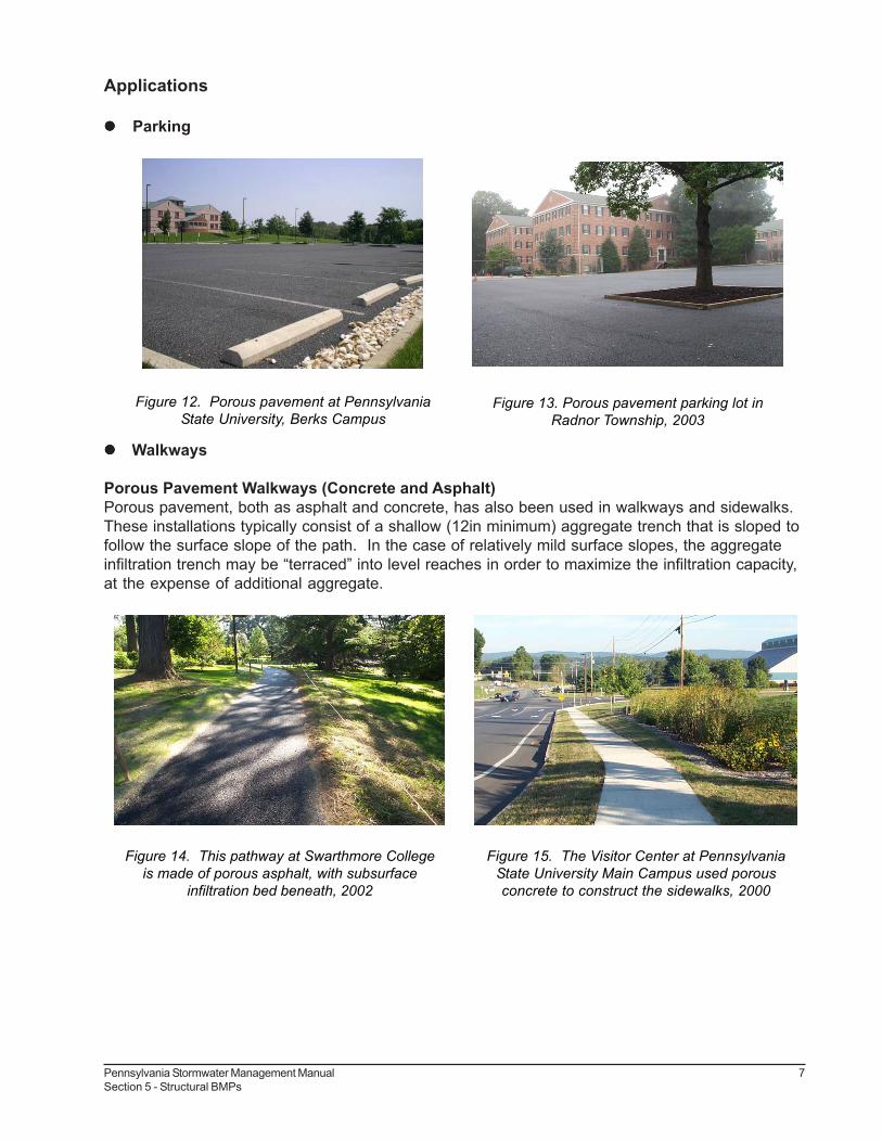
Applications
! ! ! ! ! Parking
! ! ! ! ! Walkways
Porous Pavement Walkways (Concrete and Asphalt)Porous pavement, both as asphalt and concrete, has also been used in walkways and sidewalks.These installations typically consist of a shallow (12in minimum) aggregate trench that is sloped tofollow the surface slope of the path. In the case of relatively mild surface slopes, the aggregateinfiltration trench may be �terraced� into level reaches in order to maximize the infiltration capacity,at the expense of additional aggregate.
Figure 12. Porous pavement at PennsylvaniaState University, Berks Campus
Figure 13. Porous pavement parking lot inRadnor Township, 2003
Figure 14. This pathway at Swarthmore Collegeis made of porous asphalt, with subsurface
infiltration bed beneath, 2002
Figure 15. The Visitor Center at PennsylvaniaState University Main Campus used porousconcrete to construct the sidewalks, 2000

8 Pennsylvania Stormwater Management ManualSection 5 - Structural BMPs
! ! ! ! ! Playgrounds
! ! ! ! ! Alleys
! ! ! ! ! Roof drainage; Direct connection of roof leaders and/or inlets
Figure 16. Porous asphalt playground at the Alexander-Penn-Partnership School in West Philadelphia
Figure 18. Roof drains tie directly into the infiltrationbeds at DuPont
Figure 17. Conceptual schematic showing roof drainstied directly into infiltration bed below porous pavement

9Pennsylvania Stormwater Management ManualSection 5 - Structural BMPs
! ! ! ! ! Limited use for roads and highways
Design Considerations
1. Soil Investigation and Percolation Testing Required (see Section x/x)
2. Guidelines for Infiltration Systems must be met (i.e., depth to water table, setbacks, Load-ing Rates, etc. See Section x/x).
3. The overall site shall be evaluated for potential porous pavement / infiltration areas early inthe design process, as effective porous pavement design requires consideration of grad-ing.
4. Orientation of the parking bays along the existing contours will significantly reduce theneed for cut and fill.
5. Porous Pavement and Infiltration Beds shall not be placed on areas of fill or compactedfill. Any grade adjust requiring fill shall be done using the stone sub-base material.
6. The bed bottom is not compacted, however the stone sub-base is placed in lifts and lightlyrolled according to the specifications.
7. During construction, the excavated bed may serve as a Temporary Sediment Basin or Trap.This will reduce overall site disturbance. The bed shall be excavated to within six (6)inches of the final bed bottom elevation for use as a sediment trap or basin. Followingconstruction and site stabilization, sediment shall be removed and final grades established.
8. Bed Bottoms must be level. Sloping bed bottoms will lead to areas of ponding and re-duced distribution.
9. All systems shall be designed with an overflow system. Water within the sub-surfacestone bed should never rise to the level of the pavement surface. Inlet boxes can be usedfor cost-effective overflow structures.
Figure 19. Porous asphalt pavement on this roadin Chandler, Arizona
Figure 20. Porous asphalt highway (standardasphalt shoulder) in Japan, courtesy of
Infrastructure Development Institute of Japan.

10 Pennsylvania Stormwater Management ManualSection 5 - Structural BMPs
10.While infiltration beds are typically sized to handle the increased volume from a 2-yr designstorm, they must also be able to convey and mitigate the peak of the less-frequent, moreintense storms (such as the 100-yr). Control in the beds is usually provided in the form ofan outlet control structure. A modified inlet box with an internal concrete weir and low-floworifice is a common type of control structure. The specific design of these structures mayvary, depending on factors such as rate and storage requirements, but it always mustinclude positive overflow from the system.
11.The sub-surface bed and overflow may be designed and evaluated in the same manner asa detention basin to demonstrate the mitigation of peak flow rates. In this manner, thedetention basin may be eliminated or significantly reduced in size.
12.A weir plate or weir within an inlet or overflow control structure may be used to maximizethe water level in the stone bed while providing sufficient cover for overflow pipes.
13.Perforated pipes along the bottom of the bed are necessary to evenly distribute runoff overthe entire bed bottom. Continuously perforated pipes shall connect structures (such ascleanouts and inlet boxes). Pipes shall lay flat along the bed bottom and provide for uni-form distribution of water. Depending on size, these pipes may provide additional storagevolume.
14.Roof leaders and area inlets may be connected to convey runoff water to the bed. WaterQuality Inserts or Sump Inlets shall be used to prevent the conveyance of sediment anddebris into the bed.
15.Infiltration areas should be located within the immediate project area in order to controlrunoff at its source. Expected use and traffic demands shall also be considered in porouspavement placement.
16. Control of Sediment is critical. Rigorous installation and maintenance of erosion andsediment control measures is required to prevent sediment deposition on the pavementsurface or within the stone bed. Non-woven geotextile may be folded over the edge of thepavement until the site is stabilized. The Designer should consider the placement of PorousPavement to reduce the likelihood of sediment deposition. Surface sediment shall beremoved by a vacuum sweeper and shall not be power-washed into the bed.
17. Infiltration Beds may be place on a slope by benching or terracing parking bays.Orienting parking bays along existing contours will reduce site disturbance and cut/fillrequirements.
Figure 21. Terraced infiltration beds below porous pavement at a steep site

11Pennsylvania Stormwater Management ManualSection 5 - Structural BMPs
18.The underlying infiltration bed is typically 12-36in deep and comprised of clean, uniformly-graded aggregate with approximately 40% void space. AASHTO No.3, which ranges 1.5-2.5in in gradation, is often used. Depending on local aggregate availability, both larger andsmaller size aggregate has been used. The critical requirements are that the aggregate beuniformly-graded, clean washed, and contain 40% void space. The depth of the bed isa function of stormwater storage requirements, frost depth considerations, and site grading.Infiltration beds are typically sized to mitigate the increased runoff volume from a 2-yrdesign storm.
19.While most porous pavement installations are underlain by an aggregate bed, alternativesubsurface storage products may also be employed. These include a variety of proprietary,interlocking plastic units that contain much greater storage capacity than aggregate, at anincreased cost.
20.All Porous Pavement installations must have a backup method for water to enter the stonestorage bed in the event that the pavement fails or is altered. In uncurbed lots, this backupdrainage may consist of an unpaved 2ft wide stone edge drain connected directly to thebed between the wheel stop. In curbed lots, inlets with 12in sediment traps may be re-quired at low spots. Backup drainage elements will ensure the functionality of the infiltra-tion system even if the porous pavement is ever compromised.
Figure 22. Porous parking lot w/ stone edge drain at the Morris Arboretum
Figure 23. Detail showing typical outlet control structure

12 Pennsylvania Stormwater Management ManualSection 5 - Structural BMPs
21.In areas with poorly-draining soils, infiltration beds below porous pavement may be de-signed to slowly discharge to adjacent wetlands or bioretention areas. In only extremecases (i.e. industrial sites with contaminated soils) may the aggregate bed be lined toprevent infiltration.
22.In those areas where the threat of spills and groundwater contamination is quite likely, pre-treatment systems, such as filters and wetlands, may be required before any infiltrationoccurs. In Hot Spot areas, such as truck stops, fueling stations the appropriateness ofPorous Pavement must be carefully considered. A stone Infiltration Bed located beneathstandard pavement, preceded by spill control and water quality treatment, may be moreappropriate.
23.The use of porous pavement must be carefully considered in areas where the pavementmay be seal coated or paved over due to lack of awareness, such as individual homedriveways. In those situations, a system that is not easily altered by the property ownermay be more appropriate. An example would include an infiltration system constructedunder a conventional driveway. Educational signage at porous pavement installations mayguarantee its prolonged use in some areas.
24.Proper construction, as outlined below, and long-term maintenance of the porous pave-ment system are critical to ensure its functionality for well over 20 years.
Detailed Stormwater Functions
Infiltration Area (If needed):For non-carbonate geologic areas, the minimum infiltration area shall be based on the followingequation:
Minimum Infiltration Area =Contributing Impervious Area (including infiltration area under porous pavement) / 6
For carbonate geologic areas, the minimum infiltration area shall be based on the following equa-tion:
Figure 24. Design guidelines for porous pavement with subsurface infiltration

13Pennsylvania Stormwater Management ManualSection 5 - Structural BMPs
Minimum Infiltration Area =Contributing Impervious Area (including infiltration area under porous pavement) / 4
Volume Reduction Calculations:
Peak Rate Mitigation:See Section z/z in Section 8 for Peak Rate Mitigation methodology which addresses link betweenvolume reduction and peak rate control.
Water Quality Improvement:See Section a/a in Section 8 for Water Quality Improvement methodology which addresses pollut-ant removal effectiveness of this BMP.
Construction Sequence
1. Due to the nature of construction sites, porous pavement and other infiltration measuresshould by installed toward the end of the construction period, if possible. Infiltration bedsunder porous pavement may be used as temporary sediment basins or traps provided theyare excavated to within 6-12in of the designated bed bottom elevation. Once the site isstabilized and sediment storage is no longer required, the bed is excavated to the its finalgrade and the porous pavement system is installed.
2. The existing subgrade under the bed areas shall NOT be compacted or subject to exces-sive construction equipment traffic prior to geotextile and stone bed placement.
3. Where erosion of subgrade has caused accumulation of fine materials and/or surfaceponding, this material shall be removed with light equipment and the underlying soilsscarified to a minimum depth of 6 inches with a York rake (or equivalent) and light tractor.All fine grading shall be done by hand. All bed bottoms are level grade.
4. Earthen berms (if used) between infiltration beds shall be left in place during excavation.These berms do not require compaction if proven stable during construction.
Figure 25. Unexcavated earthen berms between terraced bed bottoms

14 Pennsylvania Stormwater Management ManualSection 5 - Structural BMPs
5. Geotextile and bed aggregate shall be placed immediately after approval of subgradepreparation. Geotextile is to be placed in accordance with manufacturer�s standards andrecommendations. Adjacent strips of geotextile shall overlap a minimum of 16in. It shallalso be secured at least 4ft outside of bed in order to prevent any runoff or sediment fromentering the storage bed. This edge strip shall remain in place until all bare soils contigu-ous to beds are stabilized and vegetated. As the site is fully stabilized, excess geotextilealong bed edges can be cut back to gravel edge.
6. Clean (washed) uniformly-graded aggregate is placed in the bed in maximum 8in lifts.Each layer shall be lightly compacted, with the construction equipment kept off the bedbottom as much as possible. Once bed aggregate is installed to the desired grade, a 1inlayer of choker base course (AASHTO #57) aggregate shall be installed uniformly over thesurface in order to provide an even surface for paving.
7. The porous bituminous asphalt is installed just like standard bituminous asphalt. Porouspavement shall be laid in one lift directly over the storage bed and stone base course to a2.5in thickness. It shall not be installed on wet surfaces or when the ambient temperatureis 60 degrees Fahrenheit or lower. Compaction of the surface course shall take placewhen the surface is cool enough to resist a 10-ton roller. One or two passes is all that isrequired for proper compaction. More rolling could cause a reduction in the surface courseporosity.
Prior to installation, the porous pavement mix shall not be stored in excess of 90 minutes. Trans-porting of the mix to the site shall be in vehicles with smooth, clean dump beds that have beensprayed with a non-petroleum release agent. The mix shall be covered during transport to controlcooling.
After final rolling, no vehicular traffic of any kind shall be permitted on the surface until cooling andhardening has taken place, and in no case within the first 48 hours.
The full permeability of the pavement surface shall be tested by application of clean water at therate of at least 5 gpm over the surface, using a hose or other distribution devise. All applied watershall infiltrate directly without puddle formation or surface runoff.
Figure 26. Aggregate is placed in the infiltration bedFigure 27. Close-up view of stone for the
infiltration bed
15Pennsylvania Stormwater Management ManualSection 5 - Structural BMPs
Maintenance Issues
The primary goal of porous pavement maintenance is to prevent the pavement surface and/orunderlying infiltration bed from being clogged with fine sediments. To keep the system cleanthroughout the year and prolong its lifespan, the pavement surface should be vacuumed biannu-ally with a commercial cleaning unit. Pavement washing systems or compressed air units arenot recommended. All inlet structures within or draining to the infiltration beds should also becleaned out on a biannual basis.
Planted areas adjacent to porous pavement should be well maintained to prevent soil washoutonto the pavement. If any washout does occur it should be cleaned off the pavement immediatelyto prevent further clogging of the pores. Furthermore, if any bare spots or eroded areas areobserved within the planted areas, they should be replanted and/or stabilized at once. Plantedareas should be inspected on a semi-annual basis. All trash and other litter that is observedduring these inspections should be removed.
Superficial dirt does not necessarily clog the pavement voids. However, dirt that is ground inrepeatedly by tires can lead to clogging. Therefore, trucks or other heavy vehicles should beprevented from tracking or spilling dirt onto the pavement. Furthermore, all construction or hazard-ous materials carriers should be prohibited from entering a porous pavement lot.
Special Maintenance Considerations:
• Prevent Clogging of Pavement Surface with Sedimento Vacuum pavement twice per yearo Maintain planted areas adjacent to pavemento Immediately clean any soil deposited on pavemento Do not allow construction staging, soil/mulch storage, etc. on unprotected
pavement surfaceo Clean inlets draining to the subsurface bed twice per year
• Snow/Ice Removalo Porous pavement systems generally perform better and require less treatment than
standard pavementso Do not apply abrasives such as sand or cinders on or adjacent to porous pavemento Snow plowing is fine but should be done carefully (i.e. set the blade slightly higher
than usual)o Salt application is acceptable, although more environmentally-benign deicers are
preferable
• Repairso Surface should never be seal-coatedo Damaged areas less than 50 square feet can be patched with porous or standard
asphalto Larger areas should be patched with an approved porous asphalt

16 Pennsylvania Stormwater Management ManualSection 5 - Structural BMPs
Winter MaintenanceWinter maintenance for a porous parking lot may be necessary but is usually less intensive thanthat required for a standard asphalt lot. By its very nature, a porous pavement system with subsur-face aggregate bed has superior snow melting characteristics than standard pavement. Theunderlying stone bed tends to absorb and retain heat so that freezing rain and snow melt faster onporous pavement. Therefore, ice and light snow accumulation are generally not as problematic.However, snow will accumulate during heavier storms. Abrasives such as sand or cinders shouldnot be applied on or adjacent to the porous pavement. Snow plowing is fine, provided it is donecarefully (i.e. by setting the blade slightly higher than usual, about an inch). Salt is acceptable foruse as a deicer on the porous pavement, though non-toxic, organic deicers, applied either asblended, magnesium chloride-based liquid products or as pretreated salt, are preferable.
RepairsPotholes in the porous pavement are extremely unlikely; though settling might occur if a soft spotin the subgrade is not removed during construction. For damaged areas of less than 50 squarefeet, a declivity could be patched by any means suitable with standard pavement, with the loss ofporosity of that area being insignificant. The declivity can also be filled with porous mix. If an areagreater than 50 SF is in need of repair, approval of patch type must be sought from either theengineer or owner. Under no circumstance is the pavement surface to ever be seal coated.
Any required repair of drainage structures should be done promptly to ensure continued properfunctioning of the system.
Cost Issues
Porous Asphalt, with additives, is generally 10% to 20% higher in cost than standard asphalt on aunit area basis.
Porous Concrete as a material is generally more expensive than asphalt and requires more laborand experience for installation due to specific material constraints.
Porous Paver Blocks vary in cost depending on type and manufacturer.
The added cost of a porous pavement/infiltration system lies in the underlying stone bed, which isgenerally deeper than a conventional sub-base and wrapped in geotextile. However, this addi-tional cost is often offset by the significant reduction in the required number of inlets and pipes.Also, since porous pavement areas are often incorporated into the natural topography of a site,there generally is less earthwork and/or deep excavations involved. Furthermore, porous pave-ment areas with subsurface infiltration beds often eliminate the need (and associated costs,space, etc.) for detention basins. When all of these factors are considered, porous pavement withinfiltration has proven itself less expensive than the traditional approach. Recent installations haveaveraged between $2000 and $2500 per parking space, for the pavement and stormwater man-agement.
Specifications
The following specifications are provided for information purposes only. These specificationsinclude information on acceptable materials for typical applications, but are by no means exclusiveor limiting. The designer is responsible for developing detailed specifications for individual designprojects in accordance with the project conditions.

17Pennsylvania Stormwater Management ManualSection 5 - Structural BMPs
1. Stone for infiltration beds shall be 2-inch to 1-inch uniformly graded coarse aggregate, with awash loss of no more than 0.5%, AASHTO size number 3 per AASHTO Specifications, PartI, 19th Ed., 1998, or later and shall have voids ³ 35% as measured by ASTM-C29. Chokerbase course aggregate for beds shall be 3/8 inch to 3/4 inch uniformly graded coarseaggregate AASHTO size number 57 per Table 4, AASHTO Specifications, Part I, 13th Ed.,1998 (p. 47).
2. Non-Woven Geotextile shall consist of needled non-woven polypropylene fibers and meet thefollowing properties:
a. Grab Tensile Strength (ASTM-D4632) ≥ 120 lbsb. Mullen Burst Strength (ASTM-D3786) ≥ 225 psic. Flow Rate (ASTM-D4491) ≥ 95 gal/min/ft2
d. UV Resistance after 500 hrs (ASTM-D4355) ≥ 70%e. Heat-set or heat-calendared fabrics are not permitted.
Acceptable types include Mirafi 140N, Amoco 4547, and Geotex 451.
3. Pipe shall be continuously perforated, smooth interior, with a minimum inside diameter of 8-inches. High-density polyethylene (HDPE) pipe shall meet AASHTO M252, Type S orAASHTO M294, Type S.
4. Storm Drain Inlets and Structuresa. Concrete Construction: Concrete construction shall be in accordance with Section 1001,
PennDOT Specifications, 1990 or latest edition.
b. Precast Concrete Inlets and Manholes: Precast concrete inlets may be substituted for cast-in-place structures and shall be constructed as specified for cast-in-place. Precast struc-tures may be used in only those areas where there is no conflict with existing undergroundstructures which may necessitate revision of inverts. Precast structures shall be placed ona 6 inch bed of compacted coarse aggregate Size No. 2A. Reinforcement steel, if requiredfor handling, shall have a minimum of 2-inch cover. Handling devices, if used, shall beremovable and the holes filled with concrete. Type M standard PennDOT inlet boxes willbe modified to provide minimum 12" sump storage and bottom leaching basins, open togravel sumps in sub-grade, when situated in the recharge bed.
c. All PVC Catch Basins/Cleanouts/Inline Drains shall have H-10 or H-20 rated grates, depend-ing on their placement (H-20 if vehicular loading).
d. Steel reinforcing bars over the top of the outlet structure shall conform to ASTM A615,grades 60 and 40.
e. HDPE Flared End Section shall be installed according to manufacturers� specifications.
f. Permanent turf reinforcement matting shall be installed according to manufacturers� specifi-cations.
5. Porous Bituminous AsphaltBituminous surface course for porous paving shall be two and one-half (2.5) inches thick with abituminous mix of 5.75% to 6% by weight dry aggregate. In accordance with ASTM D6390, drain

18 Pennsylvania Stormwater Management ManualSection 5 - Structural BMPs
down of the binder shall be no greater than 0.3%. If more absorptive aggregates, such as lime-stone, are used in the mix, then the amount of bitumen is to be based on the testing proceduresoutlined in the National Asphalt Pavement Association�s Information Series 131 � �Porous AsphaltPavements� (2003) or PennDOT equivalent.
Use neat asphalt binder modified with an elastomeric polymer to produce a binder meeting therequirements of PG 76-22 as specified in AASHTO MP-1. The elastomer polymer shall be sty-rene-butadiene-styrene (SBS), or approved equal, applied at a rate of 3% by weight of the totalbinder. The composite materials shall be thoroughly blended at the asphalt refinery or terminalprior to being loaded into the transport vehicle. The polymer modified asphalt binder shall be heatand storage stable.
Aggregate shall be minimum 90% crushed material and have a gradation of:
U.S. Standard Sieve Size Percent Passing½ (12.5 mm) 1003/8 (9.5 mm) 92-984 (4.75 mm) 34-408 (2.36 mm) 14-2016 (1.18 mm) 7-1330 (0.60 mm) 0-4200 (0.075mm) 0-2
Add hydrated lime at a dosage rate of 1.0% by weight of the total dry aggregate to mixescontaining granite. Hydrated lime shall meet the requirements of ASTM C 977. The additive mustbe able to prevent the separation of the asphalt binder from the aggregate and achieve a requiredtensile strength ratio (TSR) of at least 80% on the asphalt mix when tested in accordance withAASHTO T 283. The asphaltic mix shall be tested for its resistance to stripping by water in accor-dance with ASTM D-1664. If the estimated coating area is not above 95 percent, anti-strippingagents shall be added to the asphalt.
Porous pavement shall not be installed on wet surfaces or when the ambient air temperature is 60degrees Fahrenheit or lower. The temperature of the bituminous mix shall be between 300 de-grees Fahrenheit and 350 degrees Fahrenheit (based on the recommendations of the asphaltsupplier).
6. Porous ConcreteGENERALWeather Limitations:Do not place Portland cement pervious pavement mixtures when the ambient temperature is 40degrees Fahrenheit or lower, unless otherwise permitted in writing by the Engineer.
Test Panels: Regardless of qualification, Contractor is to place, joint and cure two test panels,each to be a minimum of 225 sq. ft. at the required project thickness to demonstrate to theEngineer�s satisfaction that in-place unit weights can be achieved and a satisfactory pavement canbe installed at the site location.
Test panels may be placed at any of the specified Portland Cement pervious locations. Testpanels shall be tested for thickness in accordance with ASTM C 42; void structure in accordancewith ASTM C 138; and for core unit weight in accordance with ASTM C 140, paragraph 6.3.Satisfactory performance of the test panels will be determined by:

19Pennsylvania Stormwater Management ManualSection 5 - Structural BMPs
Compacted thickness no less than ¼� of specified thickness.
Void Structure: 12% minimum; 21% maximum.Unit weight plus or minus 5 pcf of the design unit weight.If measured void structure falls below 15% or if measured thickness is greater than ¼� less thanthe specified thickness of if measured weight falls less than 5 pcf below unit weight, the test panelshall be removed at the contractor�s expense and disposed of in an approved landfill.If the test panel meets the above-mentioned requirements, it can be left in-place and included inthe completed work.
CONCRETE MIX DESIGNContractor shall furnish a proposed mix design with proportions of materials to the Engineer priorto commencement of work. The data shall include unit weights determined in accordance withASTM C29 paragraph 11, jigging procedure.
MATERIALSCement: Portland Cement Type I or II conforming to ASTM C 150 or Portland Cement Type IP orIS conforming to ASTM C 595.
Aggregate: Use No 8 coarse aggregate (3/8 to No. 16) per ASTM C 33 or No. 89 coarse aggre-gate (3/8 to No. 50) per ASTM D 448. If other gradation of aggregate is to be used, submit dataon proposed material to owner for approval.
Air Entraining Agent: Shall comply with ASTM C 260 and shall be used to improve resistance tofreeze/thaw cycles.
Admixtures: The following admixtures shall be used:Type D Water Reducing/Retarding � ASTM C 494.A hydration stabilizer that also meets the requirements of ASTM C 494 Type B Retarding or Type DWater Reducing/Retarding admixtures. This stabilizer suspends cement hydration by forming aprotective barrier around the cementitious particles, which delays the particles from achievinginitial set.
Water: Potable shall be used.
Proportions:Cement Content: For pavements subjected to vehicular traffic loading, the total cementitiousmaterial shall not be less than 600 lbs. Per cu.yd.Aggregate Content: the volume of aggregate per cu. yd. shall be equal to 27 cu.ft. when calcu-lated as a function of the unit weight determined in accordance with ASTM C 29 jigging procedure.Fine aggregate, if used, should not exceed 3 cu. ft. and shall be included in the total aggregatevolume.Admixtures: Shall be used in accordance with the manufacturer�s instructions and recommenda-tions.
Mix Water: Mix water shall be such that the cement paste displays a wet metallic sheen withoutcausing the paste to flow from the aggregate. (Mix water yielding a cement paste with a dull-dryappearance has insufficient water for hydration).
· Insufficient water results in inconsistency in the mix and poor bond strength.· High water content results in the paste sealing the void system primarily at the bottom and
poor surface bond.

20 Pennsylvania Stormwater Management ManualSection 5 - Structural BMPs
An aggregate/cement (A/C) ratio range of 4:1 to 4.5:1 and a water/cement (W/C) ratio rangeof 0.34 to 0.40 should produce pervious pavement of satisfactory properties in regard topermeability, load carrying capacity, and durability characteristics.
INSTALLATIONPortland Cement Pervious Pavement Concrete Mixing, Hauling and Placing:Mix Time: Truck mixers shall be operated at the speed designated as mixing speed by the manu-facturer for 75 to 100 revolutions of the drum.
Transportation: The Portland Cement aggregate mixture may be transported or mixed on site andshould be used within one (1) hour of the introduction of mix water, unless otherwise approved byan engineer. This time can be increased to 90 minutes when utilizing the hydration stabilizerspecified in Section 2.2.C.4. Each truck should not haul more than two (2) loads before beingcycled to another type concrete.Prior to placing concrete, the subbase shall be moistenened and in a wet condition. Failure toprovide a moist subbase will result in a reduction in strength of the pavement.
Discharge: Each mixer truck will be inspected for appearance of concrete uniformity according toSection 2.2.C.6.d. Water may be added to obtain the required mix consistency. A minimum of 20revolutions at the manufacturer�s designated mixing speed shall be required following any additionof water to the mix. Discharge shall be a continuous operation and shall be completed as quicklyas possible. Concrete shall be deposited as close to its final position as practicable and such thatfresh concrete enters the mass of previously placed concrete. The practice of discharging ontosubgrade and pulling or shoveling to final placement is not allowed.
Placing and Finishing Equipment: Unless otherwise approved by the Owner or Engineer in writing,the Contractor shall provide mechanical equipment of either slipform or form riding with a followingcompactive unit that will provide a minimum of 10 psi vertical force. The pervious concrete pave-ment will be placed to the required cross section and shall not deviate more than +/- 3/8 inch in 10feet from profile grade. If placing equipment does not provide the minimum specified verticalforce, a full width roller or other full width compaction device that provides sufficient compactiveeffort shall be used immediately following the strike-off operation. After mechanical or otherapproved strike-off and compaction operation, no other finishing operation will be allowed. Ifvibration, internal or surface applied, is used, it shall be shut off immediately when forwardprogress is halted for any reason. The Contractor will be restricted to pavement placement widthsof a maximum of fifteen (15�) feet unless the Contractor can demonstrate competence to providepavement placement widths greater than the maximum specified to the satisfaction of the Engi-neer.
Curing: Curing procedures shall begin within 20 minutes after the final placement operations. Thepavement surface shall be covered with a minimum six-(6) mil thick polyethylene sheet or otherapproved covering material. Prior to covering, a fog or light mist shall be sprayed above thesurface when required due to ambient conditions (high temperature, high wind, and low humidity).The cover shall overlap all exposed edges and shall be secured (without using dirt or stone) toprevent dislocation due to winds or adjacent traffic conditions.
Cure Time:1. Portland Cement Type I, II, or IS � 7 days minimum.2. No truck traffic shall be allowed for 10 days (no passenger car/light trucks for 7 days).

21Pennsylvania Stormwater Management ManualSection 5 - Structural BMPs
Jointing: Control (contraction) joints shall be installed at 20-foot intervals. They shall be installedat a depth of the 1/ 4 the thickness of the pavement. These joints can be installed in the plasticconcrete or saw cut. If saw cut, the procedure should begin as soon as the pavement has hard-ened sufficiently to prevent raveling and uncontrolled cracking (normally after curing). Transverseconstructions joints shall be installed whenever placing is suspended a sufficient length of timethat concrete may begin to harden. In order to assure aggregate bond at construction joints, abonding agent suitable for bonding fresh concrete shall be brushed, tolled, or sprayed on theexisting pavement surface edge. Isolation (expansion) joints will not be used except when pave-ment is abutting slabs or other adjoining structures.
TESTING, INSPECTION, AND ACCEPTANCELaboratory Testing:The owner will retain an independent testing laboratory. The testing laboratory shall conform tothe applicable requirements of ASTM E 329 �Standard Recommended Practice for Inspection andTesting Agencies for Concrete, Steel, and Bituminous Materials as Used in Construction� andASTM C 1077 �Standard Practice for Testing Concrete and Concrete Aggregates for use in Con-struction, and Criteria for Laboratory Evaluation� and shall be inspected and accredited by theConstruction Materials Engineering Council, Inc. or by an equivalent recognized national authority.The Agent of the testing laboratory performing field sampling and testing of concrete shall becertified by the American Concrete Institute as a Concrete Field Testing Technician Grade I, or by arecognized state or national authority for an equivalent level of competence.
Testing and Acceptance:A minimum of 1 gradation test of the subgrade is required every 5000 square feet to determinepercent passing the No. 200 sieve per ASTM C 117.A minimum of one test for each day�s placement of pervious concrete in accordance with ASTM C172 and ASTM C 29 to verify unit weight shall be conducted. Delivered unit weights are to bedetermined in accordance with ASTM C 29 using a 0.25 cubic foot cylindrical metal measure. Themeasure is to be filled and compacted in accordance with ASTM C 29 paragraph 11, jigging proce-dure. The unit weight of the delivered concrete shall be +/- 5 pcf of the design unit weight.Test panels shall have two cores taken from each panel in accordance with ASTM 42 at a mini-mum of seven (7) days after placement of the pervious concrete. The cores shall be measured forthickness, void structure, and unit weight. Untrimmed, hardened core samples shall be used todetermine placement thickness. The average of all production cores shall not be less than thespecified thickness with no individual core being more than ½ inch less than the specified thick-ness. After thickness determination, the cores shall be trimmed and measured for unit weight inthe saturated condition as described in paragraph 6.3.1 of �Saturation� of ASTM C 140 �StandardMethods of Sampling and Testing Concrete Masonry Units.� The trimmed cores shall be immersedin water for 24 hours, allowed to drain for one (1) minute, surface water removed with a dampcloth, then weighed immediately. Range of satisfactory unit weight values are +/- 5 pcf of thedesign unit weight.After a minimum of 7 days following each placement, three cores shall be taken in accordancewith ASTM C 42. The cores shall be measured for thickness and unit weight determined as de-scribed above for test panels. Core holes shall be filled with concrete meeting the pervious mixdesign.
References and Additional Sources