blue hole regional parkwimberleybluehole.com › documents › phase6 › ... · tel: (512)...
TRANSCRIPT

BLUE HOLEREGIONAL PARK
100% Construction DrawingsPERMIT SET
July 15, 2010
Creation of regional park improvements.
Signatures
LANDSCAPE ARCHITECT:DESIGNWORKSHOP801 Congress Ave, Suite 330Austin, TX 78704Tel: (512) 499-0222Facsimile: (512) 499-0229
Client Name/ Title
Client Name/ Title
Client Name/ Title
Client Name/ Title
Client Name/ Title
Client Name/ Title
Date
Date
Date
Date
Date
Date
Location Map
CITY OF WIMBERLEY12111 RR12
Wimberley, TX 78676Tel: (512) 847-0025
Facsimile: (512) 847-0422
CIVIL ENGINEER ANDSURVEYING:Baker-Aicklen2108 Hunter Road, Suite 106San Marcos, TX 78666Tel: (512)392-6900Facsimile: (512) 392-6980
STRUCTURAL ENGINEER:MJ Structures812 San Antonio Street, Suite 406Austin, TX 78701Tel: (512) 693-9500
ARCHITECT:Taniguchi Architects &Associates1609 W. 6th St.Austin, Texas 78703Tel: (512) 474-7079Facsimile: (512) 474-7579
Project Description or Supplemental Information
Aug
27,
201
0 - 1
1:51
amF:
\PR
OJE
CTS
_R-Z
\455
2 W
imbe
rley
Blu
e H
ole
Reg
iona
l Par
k\D
-CA
D\0
3. C
onst
ruct
ion
Doc
umen
tatio
n\02
she
ets
and
anno
\DW
-462
8_C
over
and
Gen
eral
Info
rmat
ion_
final
.dw
g
ENVIRONMENTAL ENGINEER:PBS&J6504 Bridge Point ParkwayAustin, Texas 78730Tel: (512) 327-6840
SheetNo.
Sheet TitleSheet Index
CIVIL ENGINEERING SERIES
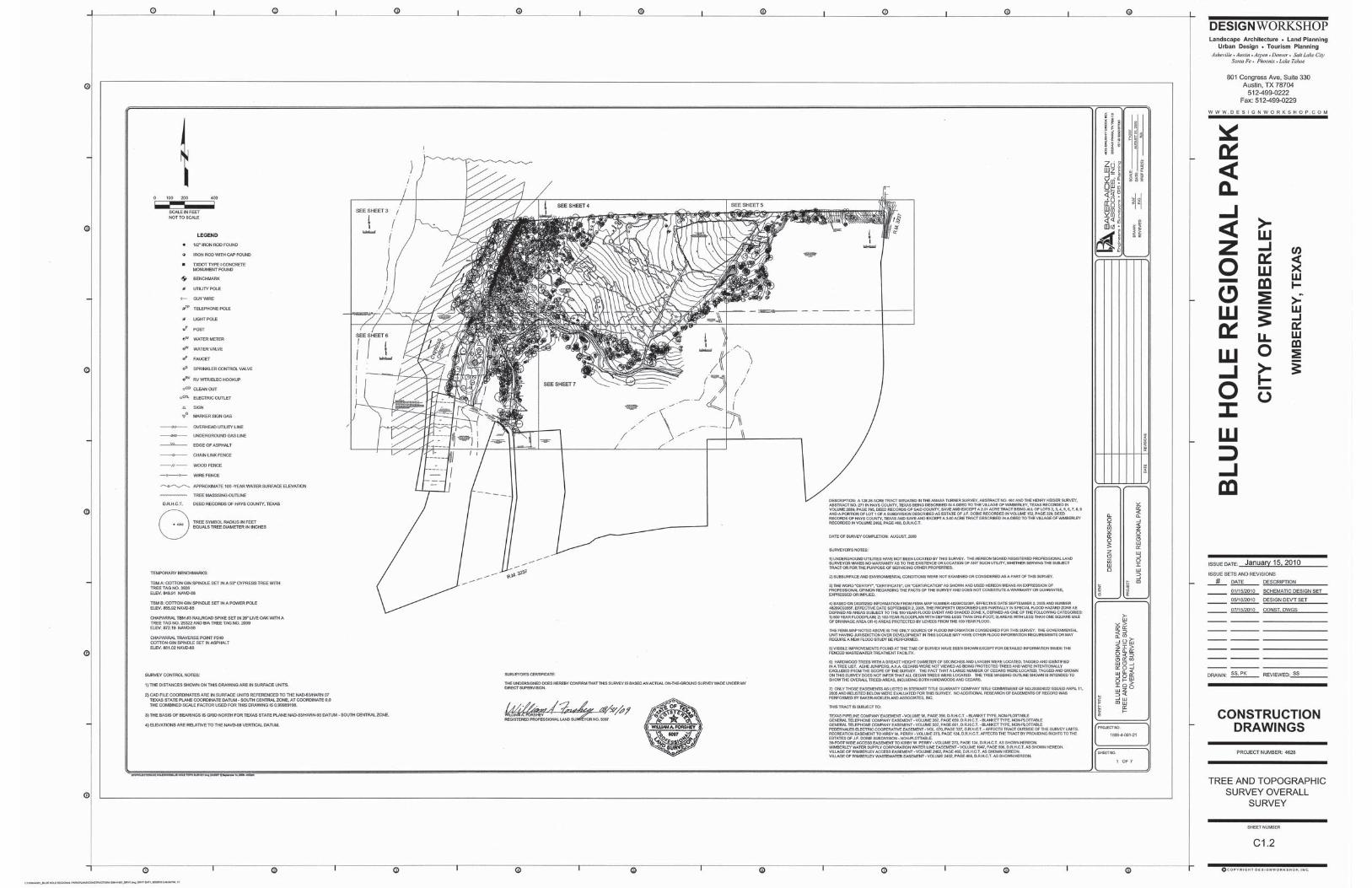
C1.2
Tree and Topographic Survey Tree List
Cover Sheet
C2.1 Overall Existing Conditions and Demolition PlanC2.2
Existing Conditions and Demolition Plan Sect. 1C2.3Existing Conditions and Demolition Plan Sect. 2C2.4Existing Conditions and Demolition Plan Sect. 3C2.5Existing Conditions and Demolition Plan Sect. 4C2.6Existing Conditions and Demolition Plan Sect. 5C2.7Existing Conditions and Demolition Plan Sect. 6C2.8Existing Conditions and Demolition Plan Sect. 7
C4.1 Overall SiteC4.2 Site Plan Section 1C4.3 Site Plan Section 2C4.4 Site Plan Section 3C4.5 Site Plan Section 4C4.6 Site Plan Section 5C4.7 Site Plan Section 6C4.8 Site Plan Section 7C5.1 Existing Drainage Area Map and CalculationC5.2 Proposed Drainage Area Map and Calculation
Grading Plan Section 3Grading Plan Section 4Grading Plan Section 5Grading Plan Section 6Grading Plan Section 7
C6.1
Overall Water, Wastewater, and Electrical Plan
C6.2
Water, Wastewater, and Electrical Plan Section 2
C6.3
Water, Wastewater, and Electrical Plan Section 3
C6.4
Water, Wastewater, and Electrical PlanSection 4
C6.5
Water, Wastewater, and Electrical Plan Section 5
C6.6
Water, Wastewater, and Electrical Plan Section 7
C6.7
LANDSCAPE SERIESL0-01 General InformationL3-00 Materials Reference PlanL3-01 Materials PlanL3-02 Materials PlanL3-03 Materials PlanL3-04 Materials PlanL3-05 Materials PlanL3-06 Materials PlanL3-07 Materials PlanL3-08 Materials PlanL3-09 Materials PlanL3-10 Materials PlanL3-11 Materials Plan
L8-00 Planting Reference PlanL8-01 Planting PlanL8-02L8-03L8-04L8-05L8-06L8-07L8-08L8-09L8-10L8-11
L9-01 Planting DetailsL9-02 Planting Details
Planting PlanPlanting PlanPlanting PlanPlanting PlanPlanting PlanPlanting PlanPlanting PlanPlanting PlanPlanting PlanPlanting Plan
L10-00 Irrigation Reference PlanL10-01 Irrigation PlanL10-02 Irrigation Plan
ARCHITECTURAL SERIESBH-A0.0 Bath House Cover SheetBH-A0.1 Bath House General NotesBH-A0.2 Bath House Schedules Wall TypesBH-A1.1 Bath House Floor PlanBH-A1.2 Bath House Finish PlanBH-A1.3 Bath House Roof PlanBH-A2.1BH-A3.1 Bath House Exterior ElevationsBH-A3.2BH-A4.1 Bath House Building Sections
Bath House Reflected Ceiling Plan
Bath House Exterior Elevations
STRUCTURAL SERIESS101 Structural NotesBH-S201 Bath House Foundation PlanBH-S202 Bath House Roof Framing Plan and DetailsCP-S201 Community Pavilion Foundation PlanCP-S202 Community Pavilion Roof Framing PlanCP-S301 Community Pavilion Structural Elev. & Details
MEP ENGINEER:F.E.U.L.S.13525 Pond Spring RoadAustin, TX 78729Tel: (512) 331-5181
July
15,
201
0- 1
00%
CO
NS
T. D
WG
. SE
T
MEP SERIES
E0.1 Electrical Notes, Abrreviations, Legend
E0.3 Electrical One-Lines and ScheduleE1.1 Electrical Plan - Ticket Office and Bath HouseE1.2 Electrical Plan - Community PavilionE1.3 Electrical Plan - Recreational Pavilion
E3.1
P0.1 General Notes, Abbreviations, LegendP0.2P1.1 Plumbing Plan and Riser - Bath House
Electrical Panel and Schedules
Plumbing Site Plan
P1.2 Plumbing Plan and Riser - Community PavilionP1.3 Plumbing Plan and Riser - Recreation PavilionP3.1 Plumbing Details
C3.1 Overall Erosion ControlC3.2 Temp. Erosion-Sed. Control & Tree Protection Sect. 1C3.3C3.4C3.5C3.6C3.7C3.8
Temp. Erosion-Sed. Control & Tree Protection Sect. 2Temp. Erosion-Sed. Control & Tree Protection Sect. 3Temp. Erosion-Sed. Control & Tree Protection Sect. 4Temp. Erosion-Sed. Control & Tree Protection Sect. 5Temp. Erosion-Sed. Control & Tree Protection Sect. 6Temp. Erosion-Sed. Control & Tree Protection Sect. 7
C6.8C7.1C7.2C7.3C7.4C7.5C7.6
Grading Plan Section 2Grading Plan Section 1Overall Grading
Site DetailsC8.1
Tree List
C2.9
C1.8
Tree and Topographic Survey/Overall Survey
LS-S202 Landscape StructuresRP-S201 Recreation Pavilion Structural Plans & Elev.S301 Typical Concrete Details
S401 Typical Framing Details
L10-03 Irrigation PlanL10-04 Irrigation Plan
C1.3Tree and Topographic SurveyC1.4Tree and Topographic SurveyC1.5Tree and Topographic SurveyC1.6Tree and Topographic SurveyC1.7Tree and Topographic Survey
C1.1 General Notes
L4-00 Layout Reference PlanL4-01 Layout PlanL4-02L4-03L4-04L4-05L4-06L4-07L4-08L4-09L4-10L4-11
Layout PlanLayout PlanLayout PlanLayout PlanLayout PlanLayout PlanLayout PlanLayout PlanLayout PlanLayout Plan
L7-01 Site DetailsL7-02 Site DetailsL7-03 Site DetailsL7-04 Site DetailsL7-05 Site DetailsL7-06 Site DetailsL7-07 Site DetailsL7-08 Site DetailsL7-09 Site DetailsL7-10 Site DetailsL7-11 Site DetailsL7-12 Site DetailsL7-13 Site DetailsL7-14 Site DetailsL7-15 Site DetailsL7-16 Site DetailsL7-17 Site DetailsL7-18 Site DetailsL7-19 Site Details
L8-12 Planting Plan
BH-A5.1BH-A5.2 Bath House Wall SectionsBH-A6.1BH-A6.2 Bath House Interior Elevations
Bath House Wall Sections
Bath House Interior Elevations
BH-A7.1BH-A7.2 Bath House Details
Bath House Details
CP-A0.0 Community Pavilion Cover SheetCP-A0.1 Community Pavilion General NotesCP-A0.2 Community Pavilion Schedules Wall TypesCP-A1.1 Community Pavilion Floor PlanCP-A1.2 Community Pavilion Finish PlanCP-A1.3 Community Pavilion Roof PlanCP-A2.1CP-A3.1 Community Pavilion Exterior ElevationsCP-A3.2CP-A4.1 Community Pavilion Building Sections
Community Pavilion Reflected Ceiling Plan
Community Pavilion Exterior Elevations
CP-A5.1CP-A6.1CP-A6.2 Community Pavilion Interior Elevations
Community Pavilion Wall SectionsCommunity Pavilion Interior Elevations
CP-A7.1CP-A7.2 Community Pavilion Details
Community Pavilion Details
RP-A0.0 Recreation Pavilion Cover SheetRP-A0.1 Recreation Pavilion General NotesRP-A0.2 Recreation Pavilion Schedules Wall TypesRP-A1.1 Recreation Pavilion Floor PlanRP-A1.2 Recreation Pavilion Finish PlanRP-A1.3 Recreation Pavilion Roof PlanRP-A2.1RP-A3.1 Recreation Pavilion Exterior ElevationsRP-A4.1 Recreation Pavilion Building Sections
Recreation Pavilion Reflected Ceiling Plan
RP-A5.1RP-A6.1
Recreation Pavilion Wall SectionsRecreation Pavilion Interior Elevations
RP-A7.1 Recreation Pavilion DetailsTS-A0.0 Tennis Storage Cover SheetTS-A0.1 Tennis Storage General NotesTS-A1.1 Tennis Storage Floor Plan and SchedulesTS-A1.2 Tennis Storage Roof Plan, Ref. Ceiling PlanTS-A3.1 Tennis Storage Ext. Elevations & Bdg SectionsTS-A5.1 Tennis Storage Wall Sections and Details
M1.1 Mechanical Plan - Ticket Office
E0.2 Electrical Site Plan
E1.4 Electrical Plan - Tennis Courts and BuildingE1.5 Electrical Plan - Amphitheatre
E3.2 Electrical SchedulesE3.3 Electrical Details
S302 Typical Masonry Details
LS-S201 Landscape Structures
July
15,
201
0- 1
00%
CO
NS
T. D
WG
. SE
T
WAYFINDING AND SIGNAGE
See Wayfinding and Signage Package for other information
GR1.01Signage and Wayfinding Location PlanGR1.02Signage and Wayfinding Location Plan

GENERALINFORMATION
L0-01
BC
ATYARD WELDED WIRE MESHWEIR LEVEL WEIGHT WITHOUT WITH VOLUME VEHICLE VERTICAL VARIES TYPICALTOP OF WALL TOP OF STEP TOP OF RAMP TRANSFORMER TOP OF SLAB TOPOGRAPHY TOP OF CONCRETE THICK TOP OF FOOTING TOP OF CURB TOP OF BACK CURB TOP AND BOTTOM SYMMETRICAL STRUCTURAL STEEL STANDARD STATION SQUARE YARD STORM SEWER SQUARE SPECIFICATIONS SEALANT SIMILAR STORM INLET SHEET SQUARE FOOT (FEET) SECTION STORM DRAIN SCHEDULE SANITARY SOUTH RIGHT RIGHT OF WAY REVISION, REVISED REQUIRED REMOVE REINFORCE(D) REFERENCE RECEPTACLE RADIUS QUANTITY PAVER PAVEMENT POLYVINYL CHLORIDE POINT, POINT OF TANGENCY PROPERTY LINE POINT OF INTERSECTION PEDESTRIAN PERFORATED POLYURETHANE POINT OF CURVATURE PARALLEL OPPOSITEOUTSIDE DIAMETER ON CENTER NOT TO SCALE NOMINAL NUMBER NOT IN CONTRACT NORTH METAL MOUNTEDMISCELLANEOUS MINIMUM MANHOLE
MEMBRANEMAXIMUM MATERIAL LIGHT LOW POINT LINEAR FEET LINEAR JOINT IRRIGATION INLET INCLUDE(D) INCH(ES) INVERT ELEVATION INSIDE DIAMETER HEIGHT HIGH POINT HORIZONTAL GENERAL GENERAL CONTRACT(OR) GALVANIZED GAUGE FOOTING FOOT (FEET) FACE OF CURB FLOW LINE FINISH FINISHED GRADE FINISHED FLOOR ELEVATION EXPANSION, EXPOSED EXISTING EACH WAY ESTIMATE EQUIPMENT EQUAL ENGINEER ELECTRICAL ELEVATION EXPANSION JOINT EACH EASTDRAWING DETAIL DIMENSION DIAMETER DEMOLISH, DEMOLITION DEGREEDIRECTION OF FLOW DOUBLE CUBIC YARD CUBIC CONTRACTOR CONTINUOUS CONSTRUCTION CONCRETE COMPACTED CLEAN OUT CENTIMETER CLEARANCE CENTER LINE CONTROL JOINT CAST IN PLACE CHAMFER CUBIC FEET CAPACITYCALIPERBOTTOM OF WALL BOTTOM OF STEP BEARING BOTTOM OF RAMP BACK OF CURB BENCHMARK BUILDING BOTTOM OF FOOTING BOTTOM OF CURB BALLED AND BURLAPPED AVERAGE ARCHITECT APPROXIMATE
@YD WWMWL WTW/O W/VOL VEH VERT VAR TYPTWTSTR TRASTSL TOPO TOC THK TFTC TBC T&BSYM STRL STL STD STASYSTSQSPECS SNT SIM SISHT SFSEC SD SCH SAN SRTROWREVREQ'D REM REINF REFRECEPRQTY PVR PVMT PVC PTPL PIPED PERF PEPC PAR OPPOD OC NTSNOM NONIC NMTL MTDMISC MINMH
MEMBMAXMATL LTLPLFLIN JTIRR INL INCL IN INV ID HTHPHORIZGEN GC GAL GAFTG FTFOC FL FIN FGFFEXPEXIST E.W. ESTEQUIP EQENG ELEC EL EJEAEDWGDTL DIM DIADEMODEGDFDBL CYCU CONTR CONTCONSTCONC COMPCOCM CLR CL CJCIPCHAM CFCAPCAL BWBSBRG BR BOC BM BLDG BF
B&BAVGARCH APPROX TABLE OF ABBREVIATIONS
820822
LINE SYMBOL LEGEND
Minor Contour
Cable TV Line
Buried Electric Line
Edge of Pavement
Storm Drain Line
Sanitary Sewer Line
Guardrail
Gas Line
Fiber Optic Line
Overhead Power Line
822
Water Edge/ Centerline
Top of Bank
Swale Centerline
100 Year Floodplain
Setback Line
Easement Line
Property Line
Floodway
Irrigation Sleeves
Curb and Gutter
Limit of Work
Chain Link Fence
Wetland
Tree Protection Fence
Custom Fence
Erosion Control Fence
Major Contour
Roof Overhang
Building Wall
Edge of Below Grade Structure
820
LAYOUT NOTES1. Layout and verify dimensions prior to construction. Bring discrepancies to the attention of the LandscapeArchitect.
2. For dimensions of the buildings, refer to the architectural drawings.
3. Written dimensions take precedence over scale. Do not scale drawings.
4. Where dimensions are called as "equal," space referenced items equally, measured to (their center lines).
5. Measurements are to face of building, wall or the fixed site improvement. Dimensions to center lines isindicated.
6. Install intersecting elements at 90 degree angles to each other unless otherwise noted.
7. Provide expansion joints where concrete flatwork meets vertical structures such as walls, curbs, steps andbuilding elements.
8. All walkways shall be located from finished face of buildings.
9. Trails without dimensions are to be staked in the field under the direction of the Landscape Architect.
10. A variety of minimal tree pruning will be necessary throughout this project in order to create road,pedestrian space and trail clearance. The contractor shall be responsible for providing a certified arborist forapplicable pruning areas under the direction of the landscape architect.
1. Source of base sheets is the Survey prepared by Baker Acklen Associates.
2. Refer to Civil Engineer's utility and precise grading plans for utility location and final grading. If actual siteconditions vary from what is shown on the plans, contact the Landscape Architect for direction as to how toproceed.
3. Verify locations of pertinent site improvements installed under other sections. If any part of this plancannot be followed due to site conditions, contact Landscape Architect for instructions prior to commencingwork.
4. Exact locations of plant materials to be approved by the Landscape Architect in the field prior to installation.Landscape Architect reserves the right to adjust plants to exact location in field.
5. Verify plant counts and square footages: Quantities are provided as Owner information only. If quantitieson plant list differ from graphic indications, then graphics shall prevail.
6. Contact the local underground utility services for utility location and identification.
7. Perform excavation in the vicinity of underground utilities with care and if necessary, by hand. TheContractor bears full responsibility for this work and disruption or damage to utilities shall be repairedimmediately at no expense to the Owner.
8. Trees shall bear same relation to finished grade as they bore to existing.
9. Trees to be planted a minimum of 1.5 feet from face of building, or pavement, except as approved byLandscape Architect.
10. Provide matching forms and sizes for plant materials within each species and size designated on thedrawings.
11. Prune newly planted trees only as directed by Landscape Architect.
12. Finish grades of shrub areas and lawns shall be 1 1/2 inches below adjacent paving or header. (Checkmulch depth and if seeded or sodded lawns).
13. Cut and remove burlap from top 1/3 of ball (if B&B material is specified or approved).
14. Landscape Architect to review plant materials at source or by photographs prior to digging or shipping ofplant materials.
LANDSCAPE PLANTING NOTES
1. Existing underground utilities are shown per available records. Verify the actual location and elevation inthe field prior to beginning construction of the new facilities. Contractor shall protect existing utilities and beresponsible for damage to utilities encountered during construction.
2. Request inspection as required 48 hours in advance of performing any work unless otherwise noted on thissheet.
3. Debris created by removal operations become the property of the Contractor and are to be legally disposedof away from the job site, unless otherwise approved by Landscape Architect.
4. Notify local underground service companies for utility finds 48 hours prior to any excavation.
5. Refer to Civil Engineer's drawings for subsurface drainage elements.
EXISTING CONDITIONS NOTES
1
F
E
D
2 3 4 5
C
B
A
1 2 3 4 5
6 7 8 9
6 7 8 9
C
DESIGN
DATENO. DESCRIPTION
ISSUE DATE:
SHEET NUMBER
REVIEWED:
PROJECT NUMBER:
DRAWN:
ISSUE SETS AND REVISIONS
4628
BLU
E H
OLE
REG
ION
AL
PAR
KC
ITY
OF
WIM
BER
LEY
WIM
BER
LEY,
TEX
AS
C O P Y R I G H T D E S I G N W O R K S H O P, I N C.
W W W . D E S I G N W O R K S H O P . C O M
Landscape Architecture � Land PlanningUrban Design � Tourism Planning
WORKSHOP
512-499-0222Fax: 512-499-0229
Austin, TX 78701801 Congress Ave, Suite 330
Asheville � Austin � Aspen � Denver� �Salt Lake City � Lake Tahoe
100%CONSTRUCTION
DOCUMENT
July 15, 2010
SS, PK, KW SS, PK
01/15/2010 SCHEMATIC DESIGN SET
05/18/2010 DESIGN DEV'T SET
07/15/2010 CONST./PERMIT SET
07�.�15�.�2010
9.0 PLANTING AND LANDSCAPINGTREE PLANTING
SITE DETAIL KEYNOTES:
9.1
TREE PLANTING IN STONE PAVING9.3
TREE PLANTING IN BOULDER WALL9.49.5
SHRUB PIT-PLANTING IN D.G.9.8
TREE PLANTING IN D.G.9.2
1/L9-01
3/L9-014/L9-015/L9-01
2/L9-02
2/L9-01329300
TREE PLANTING- SMALL TREE9.6 6/L9-01TREE PLANTING- MULTI TRUNK9.7 1/L9-02SHRUB PIT-PLANTING
PERENNIAL OR GROUNDCOVER PLANTING9.9 3/L9-029.10 4/L9-02
9.12 6/L9-02
DETAIL # SPEC #
TREE PLANTING ON SLOPE
STONE RUNNELPERENNIAL OR GROUNDCOVER PLANTING IN D.G.9.11 5/L9-02
PLANT LIST:TREES
Bald Cypress*TD1COMMON NAMESYM BOTANIC NAME SIZE NOTES
Taxodium distichum 1" calp. See noteBald Cypress*TD2 Taxodium distichum 2" calp.Bald Cypress*TD4 Taxodium distichum 4" calp.SycamorePO1 Platanus occidentalis Container grownSycamorePO2 Platanus occidentalis Container grownPecanCI2 Carya illinoinensis Container or b&bBurr OakQM1 Quercus macrocarpa Container grownBurr OakQM2 Quercus macrocarpa Container grownBurr OakQM4 Quercus macrocarpa Container or b&bTexas Red OakQB2 Quercus buckleyi Container grownTexas Red OakQB4 Quercus buckleyi Container or b&bChinqapin OakQMH2 Quercus muhlenbergii Container grownChinqapin OakQMH6 Container or b&bQuercus muhlenbergiiCedar ElmUC1 Container grownUlmus crassifoliaCedar ElmUC2 Container grownUlmus crassifoliaCedar ElmUC4 Container or b&bUlmus crassifoliaHoney MesquitePG2 Container or b&bProsopis glandulosaHuisacheAF1 Container or b&bAcacia farnesiana
1" calp.
1" calp.
1" calp.
1" calp. or mt.
2" calp.
2" calp.
2" calp.
2" calp.
2" calp.
2" calp.
4" calp.
4" calp.
4" calp.
6" calp.
2" calp.
Flame-leaf SumacRL Container grownRhus lanceolata 48"ht;30"w, mt.Red BuckeyeAP Container grownAesculus paviaYaupon HollyIV Container grownIlex vomitoria 4'ht; 3'w, mt.PossumhawID Container grownIlex deciduaTexas RedbudCCT Container grownCercis canadensis v texensisTexas PersimmonDT Container grownDiospyros texana
SHRUBS AND GRASSES
Bushy BluestemAGCOMMON NAMESYM BOTANIC NAME SIZE NOTES
Andropogon glomeratus 12" min. ht.Inland Sea OatsCL Chasmanthium latifolium 12" min. ht.Lindheimer MuhlyML Muhlenbergia lindheimeri 24"ht; 18"wSwitchgrassPV Panicum virgatumLittle BluestemSS Schizachyrium scopariumIndian GrassSN Sorghanstrum nutansEastern GamagrassTpD Tripsacum dactyloidesBunch GrassNL Nolina sp.Am. BeautyberryCA Callicarpa americanaTexas SotolDTx Dasylirion texanumAgaritaMT Mahonia trifolioataPrickly PearOT Opuntia sp.Twist-leaf YuccaYR Yucca rupicolaBlackhaw ViburnumVP Viburnum prunifoliumRoughleaf DogwoodCD Cornus drummondii
12"ht; 14"w
18"ht; 14"w
18-24"ht
24"ht; 24"w
18"ht; 18"w
16"ht; 12"w
24"ht; 24"w
10"ht; 12"w
12" min. ht.12" min. ht.12" min. ht.12" min. ht.
4" pots, 18" o.c.
3 gallon
3 gallon, 24" o.c.
1 gallon
mult. pads from base
3 gallon
3 gallon
1 gallon
3 gallon
1 gallon
PERRENIALS AND GROUNDCOVERS
Prarie VerbenaGBCOMMON NAMESYM BOTANIC NAME SIZE NOTES
Glandularia bipinnatifida 4"ht; 10"wTurk's CapMAvD Malvavisucs arboreus var.
drummondii8"ht; 12"w
Blackfoot DaisyMpL Melampodium leucanthum 6"ht; 6"wMealy Blue SageSF Salvia farinaceaDamianitaCM Chrysactinia mexicanaLyre-leaf SageSL Salvia lyrataCedar SageSR Salvia roemerianaYarrow (white)AM Achillea millefolium 6"ht; 4"w
8"ht; 4"w8"ht; 4"w8"ht; 4"w8"ht; 4"w
4" pots, 12" o.c.4" pots
SEED MIXES, TURF AND MULCHSYM TYPE SPEC #
Seed Mix- Type 1 329200
Seed Mix- Type 2
Seed Mix- Type 3
Seed Mix- Type 4
Turf- Type 1
Turf- Type 2 or 3 (refer to callouts)
Mulch Strip- Average 2'w on each side oftrails and 3'w on each side of roadway.
3292003/L7-03
4'ht; 3'w, mt.6'ht; 4'w, mt.6'ht; 4'w, mt.
KEY: calp (caliper), ht (height from base of plant to top of plant), w (width of plant at widest point), b&b (ball and burlap material) mt. (multiple trunks/canes,12"minimum caliper per cane), min. (minimum), o.c. (spacing between plants on-center)
5'ht; 3'w, mt.
4" pots, 18" o.c.
4" pots, 18" o.c.4" pots, 18" o.c.4" pots, 18" o.c.4" pots, 18" o.c.
4" pots, 18" o.c.
4" pots, 12" o.c.4" pots, 12" o.c.4" pots, 12" o.c.4" pots, 12" o.c.4" pots, 12" o.c.4" pots, 16" o.c.
* Material must be generated from seed collected on-site, or grown within 100 miles of site.
329200
329200
329200
329200
329200
329300
329300329300329300329300329300329300329300329300329300329300
See noteSee note