blow molding design guidlines
TRANSCRIPT

8/16/2019 Blow molding design guidlines
http://slidepdf.com/reader/full/blow-molding-design-guidlines 1/13
Blow-Molding Design Guide
Design & Engineering
The Custom-Pak blow molding design guide provides you with basic design tools for makingengineered blow molded parts. This guide focuses on the extrusion blow molding process. No
two designs are alike, so the mold and process must be adjusted to optimize each design.
Software products can help predict molding characteristics and our engineers are here to help
make your product great. Our design assistance is confidential and free.
A. Blow-Molding Process
B. Materials
C. Capturing the Parison
D. Exterior Cavity-Mold Design
E. Interior Core-Mold Design
F. Air Space G. Creating Structure
H. Finishing
Blow molding is a simple five-step
sequence.
A. Blow-Molding Process
1.
The first step involves mixing, melting and pushing plastic (extrusion) to form it into
a tube called a parison that will be used to make the part.
2.
A mold is used to make the part shape you desire. The mold has two halves that are
closed around the molten parison.3. Air is blown into the inside of the parison to expand the molten plastic against the
mold surface.
4. The mold is cooled to set the plastic to the new shape of the mold.
5. The molded plastic part is removed from the mold, separated from excess parison
material called flash, and finished. (Most finishing steps can be completed in-mold
but some involve secondary operations.)
B. Materials
Material selection is a critical aspect of design and should involve serious study of:

8/16/2019 Blow molding design guidlines
http://slidepdf.com/reader/full/blow-molding-design-guidlines 2/13
1. the plastic resin properties
2.
the material cost
3. the processing properties
4.
your finished-part objectives
Although there are thousands of plastic materials available, most won’t meet the needs ofyour product. Experience with blow molding grade materials is essential and we have
practical molding experience using every blow moldable material
Commodity Materials
Some of the least expensive materials are also the easiest to process. Polyethylene (PE) and
polypropylene (PP) are the most popular blow-molding resins. PE is currently less expensive
but PP tends to be stiffer which sometimes offsets the cost difference. These materials are
resistant to most chemicals. One difference is temperature performance with PE performing
better at -100 to +175 degrees F and PP performing well from -20 to +220 degrees F. These
materials usually form parts matching the principles discussed in this design guide.
Engineering Resins
Many engineering-grade resins can be blow molded. Some of the acronyms include PPO,
PC, PETG, ABS, TPE – you get the idea. These resins require special consideration prior to
molding. Most require drying before processing, specially designed extruder screws and
specific processing conditions.The design criteria in this guide may not apply to parts molded
from some engineering resins. Please obtain the correct design information for your specific
project directly from our engineering personnel.
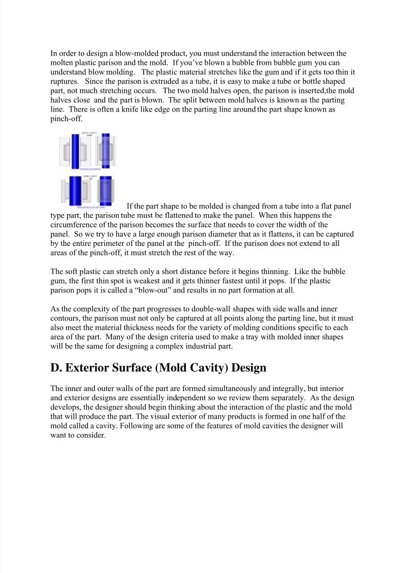
C. Capturing the Parison
8/16/2019 Blow molding design guidlines
http://slidepdf.com/reader/full/blow-molding-design-guidlines 3/13

8/16/2019 Blow molding design guidlines
http://slidepdf.com/reader/full/blow-molding-design-guidlines 4/13
Cavity – Cavity Blow Ratio = W>D
A bottle is a typical example of a blow molded part formed using 2 cavity mold halves. A
round bottle has a blow ratio that is comprised of a width=diameter and a depth=radius
(2:1). The result is excellent material distribution in a round bottle. But, not all parts will be
round. As designers start to push the limits of draw down into cavities, how far should they
go? The answer depends on the elongation elasticity of the material and how thin a wall you
are willing to accept. But as a rule of thumb, the material won’t stretch much further down
into a cavity (Depth=D) than than the width of material available to fit into the cavity(Width=W). So, try not to design your cavity-cavity part to be deeper than the width.
Cavity – Core Blow Ratio = W>2D
Many industrial parts are formed using a combination of cavity and core mold elements
where the core forms interior shapes. The core changes the blow ratio parameters.
The diameter of the cylindrical parison that forms a double wall part must allow enough
material to enter the mold to adequately form each half of the part. Half of the cylindrical
parison is used to form the exterior half (cavity) of the part and the other half of the
cylindrical parison forms the interior half (core) of the part. Since there is no flow of
material along the mold walls (only stretching), it follows that the depth of the cavity (D)
should be no more than one-half the length or width of the cavity(W). A part design utilizing
cavity depths that exceed this relationship will be subject to severe thinning or blow-out. So
like the relationship between diameter and radius, cavity-core parts should have overall blow
ratios of W>2D.
With multiple or divided cavities each cavity should meet this W>2D requirement.
The design of certain complex parts will require changes in the parting-line location in order
to stay within this relationship. These steps in the parting line must include clearance for
repeated opening and closing of the mold halves and be positioned so they do not shear the
parison during mold-close. A parting line angle of 10° draft or greater is generally designed
into mold parting line steps. When 10° draft is not possible, options like angling the mold in
the machine so that the parting lines form a positive draft relative to one another or movingmold sections can be used.
8/16/2019 Blow molding design guidlines
http://slidepdf.com/reader/full/blow-molding-design-guidlines 5/13
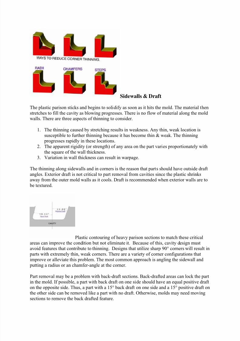
Sidewalls & Draft
The plastic parison sticks and begins to solidify as soon as it hits the mold. The material then
stretches to fill the cavity as blowing progresses. There is no flow of material along the mold
walls. There are three aspects of thinning to consider.
1. The thinning caused by stretching results in weakness. Any thin, weak location is
susceptible to further thinning because it has become thin & weak. The thinning
progresses rapidly in these locations.
2. The apparent rigidity (or strength) of any area on the part varies proportionately with
the square of the wall thickness.
3. Variation in wall thickness can result in warpage.
The thinning along sidewalls and in corners is the reason that parts should have outside draft
angles. Exterior draft is not critical to part removal from cavities since the plastic shrinks
away from the outer mold walls as it cools. Draft is recommended when exterior walls are to be textured.
Plastic contouring of heavy parison sections to match these criticalareas can improve the condition but not eliminate it. Because of this, cavity design must
avoid features that contribute to thinning. Designs that utilize sharp 90° corners will result in
parts with extremely thin, weak corners. There are a variety of corner configurations that
improve or alleviate this problem. The most common approach is angling the sidewall and
putting a radius or an chamfer-angle at the corner.
Part removal may be a problem with back-draft sections. Back-drafted areas can lock the part
in the mold. If possible, a part with back draft on one side should have an equal positive draft
on the opposite side. Thus, a part with a 15° back draft on one side and a 15° positive draft on
the other side can be removed like a part with no draft. Otherwise, molds may need moving
sections to remove the back drafted feature.
8/16/2019 Blow molding design guidlines
http://slidepdf.com/reader/full/blow-molding-design-guidlines 6/13
Shrinkage & Warpage
Shrinkage varies by material, the rate of temperature change and the thickness of the material.
For PP and PE materials, the material thickness is the best predictor. Thin wall parts may
shrink as little as 1% and thick parts in excess of 10%. A .060” thick part will shrink
approximately 1.65% as it cools and a .125” thick part will shrink about 1.85%. The
shrinkage expectation must be taken into consideration when setting the mold size.
Designs that allow wall thinning variation to occur in the part may result in warped parts. Thethin areas will shrink less before cooling than the thick areas. The variation in shrinkage rates
and distances can cause the part to warp. Some wall thickness & shrinkage variation occurs
in every molded product because the cooling rate of the plastic will vary. The skin of the
material against the mold metal will cool and take a set before the material not actually
touching the mold metal. The result is a tendency for outer walls to warp inward and is offset
by the tendency of the inner wall to warp outward. The use of structural ribs, welds between
walls, arcs or steps can create a structure that helps reduce warpage.
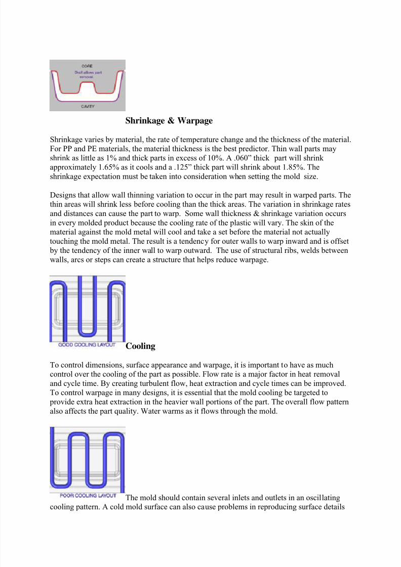
Cooling
To control dimensions, surface appearance and warpage, it is important to have as much
control over the cooling of the part as possible. Flow rate is a major factor in heat removal
and cycle time. By creating turbulent flow, heat extraction and cycle times can be improved.
To control warpage in many designs, it is essential that the mold cooling be targeted to
provide extra heat extraction in the heavier wall portions of the part. The overall flow pattern
also affects the part quality. Water warms as it flows through the mold.
The mold should contain several inlets and outlets in an oscillatingcooling pattern. A cold mold surface can also cause problems in reproducing surface details
8/16/2019 Blow molding design guidlines
http://slidepdf.com/reader/full/blow-molding-design-guidlines 7/13
such as texture. Tooling engineers can target water lines near each critical section of the mold
to provide the dimensional control and appearance you need.
Venting
When the mold closes the parison is captured at the pinch-off. A certain amount of air is
trapped between the outside of the parison and the mold cavity. When air is blown to expand
the parison, the trapped air becomes compressed by the expanding parison until an interior –
exterior pressure equilibrium is reached. When this occurs, the parison will not completelytouch the mold wall. The results are visible surface abnormalities, loss of texture &
engraving detail, the appearance of creases and drag-lines, and longer cycles from poor mold
cooling.
Venting can be easily located at the edge of any insert in the cavity. Slotted vent inserts or
porous metals can be purchased and fit into nearly any location. Some venting methods will
produce visible markings on the finished part. Texture, inserts and other techniques can be
employed to mask the markings made at the vent location.
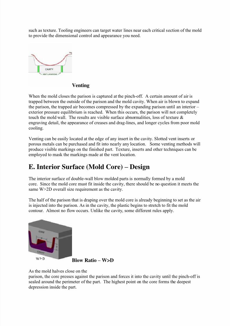
E. Interior Surface (Mold Core) – Design
The interior surface of double-wall blow molded parts is normally formed by a mold
core. Since the mold core must fit inside the cavity, there should be no question it meets the
same W>2D overall size requirement as the cavity.
The half of the parison that is draping over the mold core is already beginning to set as the air
is injected into the parison. As in the cavity, the plastic begins to stretch to fit the mold
contour. Almost no flow occurs. Unlike the cavity, some different rules apply.
Blow Ratio – W>D
As the mold halves close on the
parison, the core presses against the parison and forces it into the cavity until the pinch-off is
sealed around the perimeter of the part. The highest point on the core forms the deepest
depression inside the part.
8/16/2019 Blow molding design guidlines
http://slidepdf.com/reader/full/blow-molding-design-guidlines 8/13
If the double-wall part design has a dividing wall between two compartments, this wall is
formed by stretching the plastic into a groove in the mold core. As the plastic begins
stretching into a groove, it begins to thin. If the groove is too deep, the plastic quickly
reaches the point where it thins until the internal air blows-out through the wall to the outside
of the part. No part will form.
Because of this, there is one simple yet absolute rule, which governs the design of the ribs or
divisions between compartments. The depth (D) of the groove between core sections must not
exceed the width (W) of the rib W>D.
This rule also applies to other structural shapes. For example, a 1” tall, round post in the
center of a tray would have to be 1” or more in diameter.
If the part design requires a mold parting line which steps to various levels for the part to
function properly, then the core must have a positive draft on these steps at the pinch-off to
match the pinch-off on the cavity element of tooling. Varying pinch-off levels can change the
W-D relationships of nearby pockets or ribs. All of the levels within a part must pass the
W>D requirement in each direction.
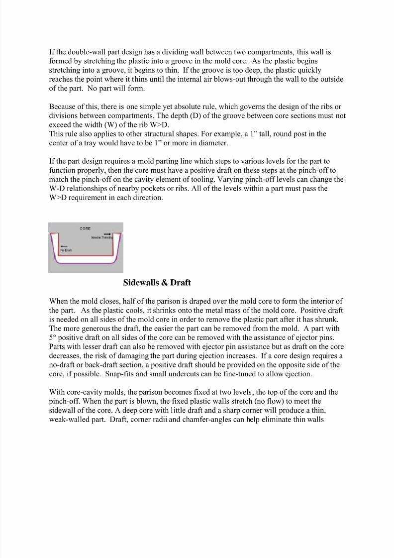
Sidewalls & Draft
When the mold closes, half of the parison is draped over the mold core to form the interior of
the part. As the plastic cools, it shrinks onto the metal mass of the mold core. Positive draft
is needed on all sides of the mold core in order to remove the plastic part after it has shrunk.
The more generous the draft, the easier the part can be removed from the mold. A part with
5° positive draft on all sides of the core can be removed with the assistance of ejector pins.
Parts with lesser draft can also be removed with ejector pin assistance but as draft on the core
decreases, the risk of damaging the part during ejection increases. If a core design requires a
no-draft or back-draft section, a positive draft should be provided on the opposite side of the
core, if possible. Snap-fits and small undercuts can be fine-tuned to allow ejection.
With core-cavity molds, the parison becomes fixed at two levels, the top of the core and the pinch-off. When the part is blown, the fixed plastic walls stretch (no flow) to meet the
sidewall of the core. A deep core with little draft and a sharp corner will produce a thin,
weak-walled part. Draft, corner radii and chamfer-angles can help eliminate thin walls
8/16/2019 Blow molding design guidlines
http://slidepdf.com/reader/full/blow-molding-design-guidlines 9/13
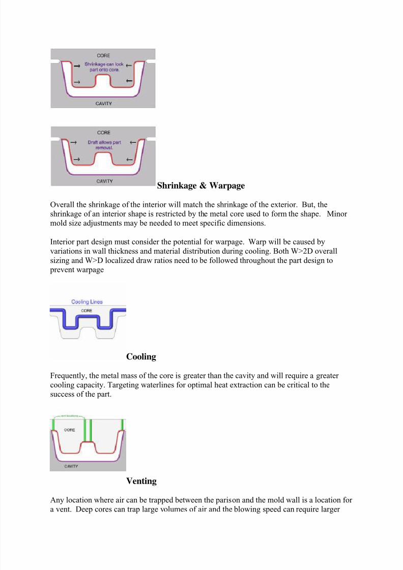
Shrinkage & Warpage
Overall the shrinkage of the interior will match the shrinkage of the exterior. But, the
shrinkage of an interior shape is restricted by the metal core used to form the shape. Minor
mold size adjustments may be needed to meet specific dimensions.
Interior part design must consider the potential for warpage. Warp will be caused by
variations in wall thickness and material distribution during cooling. Both W>2D overall
sizing and W>D localized draw ratios need to be followed throughout the part design to
prevent warpage
Cooling
Frequently, the metal mass of the core is greater than the cavity and will require a greater
cooling capacity. Targeting waterlines for optimal heat extraction can be critical to the
success of the part.
Venting
Any location where air can be trapped between the parison and the mold wall is a location fora vent. Deep cores can trap large volumes of air and the blowing speed can require larger

8/16/2019 Blow molding design guidlines
http://slidepdf.com/reader/full/blow-molding-design-guidlines 10/13

8/16/2019 Blow molding design guidlines
http://slidepdf.com/reader/full/blow-molding-design-guidlines 11/13
when the mold closes. It is a good idea to ask for a simulation test on deep parts that might
produce webbing.
Compression Molding
Many functional designs are greatly enhanced by the inclusion of compression-molded tabs,
locks or mounting surfaces.
Compression molded tabs can be added at any point along the mold parting line on the same plane as the pinch-off. To change the angle of a tab relative to the basic parting plane, you
must create a mold parting line at the desired angle. This can be done with angled parting line
steps or inserts along the perimeter of the part or moving inserts within the part.
When blow-molded parts are to be combined with other parts through the use of mounting
screws, bolts or rivets, an exceptionally strong mounting surface can be provided by
compressing the inner and outer walls together. The two walls can be compressed together at
nearly any angle or location as long as there is ample room surrounding the compression for
good airflow and as long as the mold halves can close without interference.
By compression molding inner and outer walls together, the part rigidity and straightness can be improved significantly. It is also an excellent way to provide stacking strength when
dealing with heavy loads
G. Creating Structure
The double walls in blow molded parts provide engineers with a tremendous opportunity to
create structure within the plastic part. A properly designed double-wall part will be
substantially stronger than a ribbed single-wall part of equal weight and can easily
outperform metals in many applications. There are several ways to add strength to blow
molded part designs.
Weld Cones & Tack-Offs
By designing the mold to close in specific locations to a distance that is less than thecombined thickness of inner and outer walls, a weld is formed. The amount of compression
8/16/2019 Blow molding design guidlines
http://slidepdf.com/reader/full/blow-molding-design-guidlines 12/13
sets the strength of the weld. By adjusting the distance between mold halves to between 60%
and 80% of the combined thickness of inner and outer walls, the weld can resist both
compression and separation forces.
The location of welds within a part will determine the stiffness and ability to support loads.
Designers must remember to pay attention to blow ratios between welds.
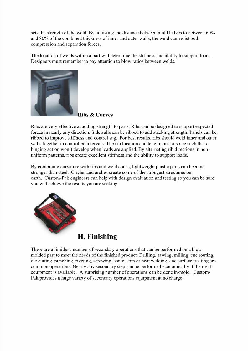
Ribs & Curves
Ribs are very effective at adding strength to parts. Ribs can be designed to support expected
forces in nearly any direction. Sidewalls can be ribbed to add stacking strength. Panels can be
ribbed to improve stiffness and control sag. For best results, ribs should weld inner and outer
walls together in controlled intervals. The rib location and length must also be such that a
hinging action won’t develop when loads are applied. By alternating rib directions in non-
uniform patterns, ribs create excellent stiffness and the ability to support loads.
By combining curvature with ribs and weld cones, lightweight plastic parts can become
stronger than steel. Circles and arches create some of the strongest structures on
earth. Custom-Pak engineers can help with design evaluation and testing so you can be sure
you will achieve the results you are seeking.
H. Finishing
There are a limitless number of secondary operations that can be performed on a blow-
molded part to meet the needs of the finished product. Drilling, sawing, milling, cnc routing,
die cutting, punching, riveting, screwing, sonic, spin or heat welding, and surface treating are
common operations. Nearly any secondary step can be performed economically if the right
equipment is available. A surprising number of operations can be done in-mold. Custom-
Pak provides a huge variety of secondary operations equipment at no charge.

8/16/2019 Blow molding design guidlines
http://slidepdf.com/reader/full/blow-molding-design-guidlines 13/13
Decorating molded parts requires planning in the design stage. For
heat transfer or hot stamp decorating, the part design must provide a means to support the
tonnage of the stamping process. For in-mold labels, magazines to hold the labels and mold
surface locators must be prepared. For embossed plaques, the attachment method should be
included in the part design.
Texture is commonly applied to mold surfaces. Blow molding textures are typically etched
.008” to .012” deep in the mold surface (much deeper than injection molding). Draft may be
needed to allow the texture to form and still release from the mold. There are many ways toget the appearance that you want in your blow molded parts. We can help you make sure your
design will look great long after the consumer has made their purchase.