blog.triadtechnologies.comblog.triadtechnologies.com/catalogs/electromechanical/parker_cat 8… ·...
TRANSCRIPT

Daedal Manually Driven Positioning Slides and Stages

Parker offers complete engineered systems.
Parker world headquarters in Cleveland, Ohio.
Training
Parker’s best-in-class technology training includes hands-on classes, Web-based instruction, and comprehensive texts for employees, distributors, and customers. Parker
also provides computer-based training, PowerPoint presentations, exams, drafting and simulation software, and trainer stands.
parkermotion.com
Our award-winning Web site is your single source for
• Product information• Downloadable catalogs• Motion-sizing software• 3D design files• Training materials• Product-configuration
software• RFQ capabilities• Videos and application
stories
24/7 Emergency Breakdown Support
The Parker product information center is available any time of the day or night at 1-800-C-Parker. Our operators will connect you with a live, on-call representative who will identify replacement parts or services for all motion technologies.
A Fortune 300 company with annual sales exceeding $12 billion and more than 400,000 customers in 43 countries, Parker Hannifin is the world’s leading supplier of innovative motion control components and system solutions serving the industrial, mobile, and aerospace markets. We are the only manufacturer offering customers a choice of electromechanical, hydraulic, pneumatic, or computer-controlled motion systems.
Total System Solutions
Parker’s team of highly qualified application engineers, product development engineers, and system specialists can turn pneumatic, structural, and electromechanical products into an integrated system solution. Moreover, our Selectable Levels of Integration™ allows you to choose the appropriate system, subsystem, or component to meet your specific need.
ParkerHannifin
Corporation
© Copyright 2009, Parker Hannifin Corporation. All rights reserved.
First in Delivery, Distribution, and Support
In today’s competitive, fast-moving economy, what good is an application that isn’t ready on time? This is especially true when compressed design cycles make the quick delivery of critical components essential. With factories strategically located on five continents, Parker offers an unrivaled delivery record, getting solutions out our door and onto your floor faster than ever.
Parker also has the industry’s largest global distribution network, with more than 8,600 distributors worldwide. Each of these locations maintains ample product inventory to keep your downtime to a minimum. And many distributors have in-house design capabilities to support your system and subsystem requirements.
Throughout the design process, Parker’s factory-trained electromechanical engineers work hand in hand with you and day or night at 1-800-C-Parker. Our operators will connect you with a live, on-call representative who will identify replacement parts or services for all motion technologies.

Parker Hannifin CorporationElectromechanical Automation DivisionIrwin, Pennsylvania �
www.parkermotion.com
Cro
ssed
Ro
ller
Pos
ition
ers
Bal
l Bea
ring
P
ositi
oner
sE
ngin
eeri
ng
Ref
eren
ceR
ota
ry
Pos
ition
ers
Cro
ssed
Ro
ller
Slid
esB
all B
eari
ng
Slid
esA
cces
sori
es
Welcome!For over forty years, Parker Daedal has been the leader in supplying manual positioners to industries and laboratories around the world. These positioners are utilized for applications that include laser beam directing, fiber optics alignment, assembly fixturing, tooling, microscope specimen positioning, camera focusing, and many others — even experiments in outer space.
• Precision quality • Budget friendly• Largest selection• Easy multi-axis configuration• No maintenance• Vacuum preparation and custom options
Parker Daedal has thousands of ball slides, crossed roller slides and linear and rotary manual positioning stages. All Parker Daedal slides and stages are precision grade products, offering low friction, accurate, and smooth linear motion.
Parker Daedal free-travel linear slides and precision point-to-point positioners are available in sizes ranging from less than half of an inch wide to 6 inches wide, travels from 1 to 30+ inches, and payload capacities to hundreds of pounds. They are available as single axis units or two and three axis systems — all offered by model number and delivered complete, with no assembly required. Rotary stages are also available for easy configuration of linear/rotary combinations.
Parker Electromechanical Automation offers one of the broadest manual positioning lines in the industry. The following pages of this product guide will help you find the best fit for every application. If you cannot find what you are looking for in these pages, please do not hesitate to call our application team at 724-861-8200. Parker Electromechanical Automation Division has extensive machining and testing capabilities to produce a solution for your application even if it is not shown in the product guide.
© Copyright 2009 Parker Hannifin Corporation
Table of ContentsIntroduction
2-3 Parker Partners in Automation & Support4-5 Selectable Levels of Integration™
6-7 Parker Products and Technologies8-�2 Parker Daedal Manual Products and Technologies
Ball Bearing Slides�3-�5 Overview�6-20 1.25” Wide or Less (3500, 3900)2�-22 1.75” Wide (4000, 4100, 4200, 4300)23-25 2.62” Wide (4500, 4600, 4700, 4800)26-27 5” Wide (4400)
28 6” Wide (4900)
Crossed Roller Slides35-38 Overview
39 1.496” (38 mm) Wide (SW038)40-4� 1.75” Wide (CR4000, CR4100, CR4200, CR4300)42-43 1.97” (50 mm) Wide (SE050, SP050)44-45 2.62” Wide (CR4500, CR4600, CR4700, CR4800)46-47 2.95” (75 mm) Wide (SE075, SP075)48-49 3.94” (100 mm) Wide (SE100, SP100)
50 5” Wide (CR4400)5� 6” Wide (CR4900)
Ball Bearing Positioners6�-63 Overview64-67 1.25” Wide or Less (MM-1/3, 3900)68-73 1.75” Wide (4000, 4100, 4200, 4300)74-79 2.62” Wide (4500, 4600, 4700, 4800)80-83 5” Wide (4400)84-86 6” Wide (4900)
Crossed Roller Positioners89-9� Overview92-96 1.75” Wide (CR4000, CR4100, CR4200, CR4300)
97 1.97” (50 mm) Wide (SC050, SK050)98-�0� 2.62” Wide (CR4500, CR4600, CR4700, CR4800)
�02 2.95” (75 mm) Wide (SC075, SK075)�03 3.94” (100 mm) Wide (SC100, SK100)
�04-�07 5” Wide (CR4400)�08-��0 6” Wide (CR4900)
Rotary Positioners��5-��6 Overview
��7 1.88 – 2.62” Diameter (2500)��8 2.38” Diameter (4575)��9 2.75 – 4.75” Diameter (10000, 20000 )
�20-�2� 5 – 12” Diameter (30000)
Accessories�23 Overview
�24-�27 Z-Axis Brackets�28-�29 Drive Mechanisms�30-�32 Optical Mounts
Engineering Reference�33-�35
Part Number Index�36-�42
Parker Daedal Manually Driven Slides and Positioners
To find a specific model, refer to the part number index on
pages 136-142.

Parker Hannifin CorporationElectromechanical Automation Division
Irwin, Pennsylvania2
www.parkermotion.com
Manual Positioners
Today’s positioning applications demand performance in quality, throughput, productivity and precision. Miniaturization of semiconductor, electronics and life science applications have created the need to partner with companies that have the experience and products to meet stringent specifications for smaller, more precise motion positioning solutions.
Parker’s dedicated electromechanical business leads the way for manual positioning to efficiently assist in many industries including:
• Semiconductor• Electronics• Packaging• Life science• Medical equipment• Laboratory research• Optical inspection & adjustments• Laser cutting & marking• Automotive manufacturing and assembly• Printing• Material handling• Military applications
Since 1969 Parker has been producing these precision slides in Pennsylvania. These slides are precision grade products, offering low friction, accurate, and smooth linear motion. The stages offer digital micrometers, imperial and metric micrometers, knobs, cranks, hand wheels, and fine lead screws for drives. Each of these precision machined assemblies is offered with either cross roller bearings for high load capacities or caged ball bearings for smooth motion.
Partners in Automation
2
www.parkermotion.com

Parker Hannifin CorporationElectromechanical Automation DivisionIrwin, Pennsylvania 3
www.parkermotion.com
Parker Automation Technology CentersParker Automation Technology Centers are a network of premier product and service providers who can serve you locally for your automation needs. Each Automation Technology Center is certified to have completed significant product training and has the ability to provide subsystem solutions with local support.
Industry’s Best Lead Times#1 rated, industry-leading, on-time delivery to customer-requested ship dates. For more than 3 years and over 100 thousand manual products, we have delivered 100% on-time to our agreed upon customer request delivery date for the Parker manual slide and stage product lines.
www.parkermotion.comThe Parker Electromechanical Automation site offers the most extensive online support tools in the industry, including:
• Complete online catalog• FAQ database with more than 500 answers to common
questions• Interactive product sizing and selection tool• Comprehensive CAD drawings and 3-D models for
electronic and mechanical products• User guides and detailed product specifications• Latest software and firmware revisions• Application case studies and videos• Custom solutions photo library• Innovative technology white papers
One-on-One with a Motion Control ExpertToll-Free Applications Engineering Assistance
When you have urgent questions, expert answers are only a phone call away. Our team of experienced engineers is ready to take your call. These engineers have practical field experience and can provide you with application and product assistance throughout the stages of your project and for the life of the product. For presale support, including sizing and selecting systems, call 800-245-6903 (724-861-8200 outside the US). For post-sale support with technical questions on programming and troubleshooting, call 800-358-9070 (707-584-7558 outside the US). Our staffing and support tools allow us to resolve most issues and get your project rolling in less than one hour.
Customization and ServicesParker has a Custom Systems Group staffed by experienced engineers and technicians who utilize systematic processes for handling component modifications or complete one-of-a-kind systems.
The System is the Product
Many of the components shown in this catalog are modified specifically to customer request and need. Parker system customers can receive many optional services such as:
• 3-D custom assembly drawings• Electronics integration• Finite element analysis• Life load testing• Integration with the breadth of
Parker product
Our advanced manufacturing and assembly process allows us to build quality and consistency into every element of your motion system. Each mechanical system is fully assembled prior to shipment and each component is properly handled to protect finish and appearance. Performance and specifications are verified with state-of-the-art testing, including:
Cleanroom Testing
Parker is equipped with particulate testing to certify materials for cleanroom ratings.
EMI Testing
Parker has an EMI test chamber, which allows us to test equipment to verify levels of electromagnetic interference.
Precision Metrology Lab
When precision is critical to your process, you need validated, proven performance data. Parker certifies all precision-grade positioners using state-of-the-art laser interferometers, and provides reports to validate accuracy and bidirectional repeatability.
24/7 Emergency Breakdown ReferralsThe Parker product information center at 800-C-PARKER offers live operators 24/7 to help identify replacement parts or services.
Parker Unrivaled Support

Parker Hannifin CorporationElectromechanical Automation Division
Irwin, Pennsylvania4
www.parkermotion.com
Manual Positioners
Motion ControllersCatalog #8500
Parker motion controllers are powerful designs that have the processing power to coordinate multiple axes of motion. Parker controllers have advanced features built in, such as kinematics transformation for the control of robots and other non-linear functions. Each Parker controller comes with free libraries for Visual Basic® and Visual C++®.
HMI (Human-Machine Interface)Catalog #8500
Parker offers HMI solutions for any application from simple pushbutton replacement to sophisticated networking, multimedia and data logging requirements. Parker pre-loads Interact or InteractX HMI software on PowerStation industrial computers to provide a ready-to-go HMI solution. This bundled approach reduces development and integration time for your HMI project.
Whether using one component or an entire system, Parker has the right solution. In addition to the Parker manual positioning slides and stages, Parker Electromechanical Automation Division offers a vast array of motion and control products including:
Parker Products and Technologies
To request a catalog or for complete on-line information, go to www.parkermotion.com

Parker Hannifin CorporationElectromechanical Automation DivisionIrwin, Pennsylvania 5
www.parkermotion.com
DrivesCatalog #8500
Parker drives are digital designs that deliver a maximum amount of power output and performance in minimal package size. These drives have industry-leading power density and smart digital designs with features to ease integration and start-up.
MotorsCatalog #8500
Using advanced technologies, Parker rotary motors provide maximum performance and value. Our exposed-lamination designs provide maximum torque per package size, and the motor designs provide cog-free rotary motion for the best low-speed smoothness. Patented linear motor designs provide the greatest winding uniformity and accuracy in the industry, and range from the smallest linear motor on the market to the largest force capacity.
GearheadsCatalog #1810
High-precision designs, Parker gearheads have less than three arc-min of backlash. They have an industry-leading two-year warranty.
Positioning TablesCatalog #8092
Parker multi-axis positioning tables integrate linear motors or ground ballscrews. The designs combine the low cost of extruded aluminum with machined bases allowing “out of the box” submicron precision. Our positioning tables are modular designs that easily accommodate flexible configurations such as XY and XYZ.
ActuatorsCatalog #AU03 1894-2/US
Parker actuators are modular single-axis actuators that can be easily configured in multi-axis systems. These actuators are screw- or belt-driven and give the designer a great deal of flexibility to apply the right actuator technology to meet the application needs for accuracy, speed and distance.
End EffectorsCatalog #0900P-4
With the broadest range of automation products in the industry, Parker provides pneumatic grippers, rotary actuators and vacuum components for a wide range of applications.
Structural FramingCatalog #1816-2
Parker Industrial Profile Systems provide full engineering, fabrication and assembly for any structural design. We provide the profiles, fasteners and accessories to complete any system. The only limitation is your imagination.
I/OCatalog #8500
The Parker I/O system is a modular and flexible remote I/O system designed to work with today’s common fieldbuses. The modular design of the Parker I/O allows the user to choose the number and type of I/O points that best suit each application.
SystemsCatalog #8092
Parker’s systems combine the breadth of our motion control solutions into XY systems, Cartesian robots, gantry systems, or completely custom configurations.
Parker Products and Technologies

Parker Hannifin CorporationElectromechanical Automation Division
Irwin, Pennsylvania6
www.parkermotion.com
Manual Positioners
SystemsMachine builders and OEMs often choose to integrate more than a manual slide or stage into their machine. They have confidence in knowing that our knowledge, experience, and support will ensure that their goals are met. Minimal design engineering ensures component compatibility from a single source.
Component ProductsParker Daedal has thousands of ball slides, cross roller slides and linear and rotary manual positioning stages. If you have the capability and experience to develop your own systems, our innovative, easy-to-use products will help you get the job done. Parker provides short lead times, large selection, and proven reliability. All Parker Daedal slides and stages are precision machined and easy to install.
Please review the next several pages for a technical overview of our manual product line.
Subsystems and Bundled ProductsFor a cost-effective and efficient solution, Parker offers bundled or kitted systems. We offer multi-axis solutions to deliver a configured subsystem ready for installation. If electromechanical motion is included, Parker configuration and setup software accommodates the rest of the product line, making start-up a snap. Combining this with our custom product modification capabilities gives the machine builder an economical custom-fit solution, with reduced engineering effort, straightforward integration, and modular compatibility.
Parker’s Selectable Levels of Integration™ is a philosophy of product development and management that allows the machine builder to select an appropriate system, subsystem, or component to meet a specific need.
Parker has solutions for machine builders of all types, from those who want a complete integrated system to those who want to build their own system from “best of breed” components.
Parker Selectable Levels of Integration™

Parker Hannifin CorporationElectromechanical Automation DivisionIrwin, Pennsylvania 7
www.parkermotion.com
Cro
ssed
Ro
ller
Pos
ition
ers
Bal
l Bea
ring
P
ositi
oner
sE
ngin
eeri
ng
Ref
eren
ceR
ota
ry
Pos
ition
ers
Cro
ssed
Ro
ller
Slid
esB
all B
eari
ng
Slid
esA
cces
sori
es
Where to find Parker Daedal Products and Technologies
Using our Catalog This catalog is divided into several sections based on primary distinguishing characteristics such as drive technology, degree of precision, travel range, and load capacity. A brief overview and selection is provided on the following pages.
If you don’t find exactly what you are looking for, please contact us for information on other suitable Daedal and Parker products.
Visit our WebsiteComplete up-to-date technical assistance can be found on the web at www.parkermotion.com. This includes all the latest information on current products, new product introductions, local assistance and support, plus a comprehensive “Engineering Reference Library.”
• Complete product catalogs• Product selection wizards• Performance charts and graphs• Engineering data and calculations• CAD drawings• Local service and support directory• On-line purchasing• Application stories and videos

Parker Hannifin CorporationElectromechanical Automation Division
Irwin, Pennsylvania8
www.parkermotion.com
Manual Positioners
Manual Slides Overview
Functional Comparison
Smoothness FrictionStraightness/
Flatness Accuracy Load Capacity
Ball Bearing Slide Exceptional Extremely Low Very Good Moderate
Crossed Roller Slide Very Good Very Low Very Good High
Ball Bearing SlidesPages 13-34
Parker Daedal ball slides are mechanically simple linear bearings, which are designed and assembled to provide exceptional smoothness and linear straight line accuracy. This is achieved by the ball and rod linear bearing design.
The ball and rod bearings on Parker Daedal ball slides consist of two rows of hardened steel balls, each preloaded between four hardened ground steel rods. This design provides ultra-smooth, extremely low-friction motion by reducing the contact area between the balls and the ways. Additionally this design provides extremely good straight line and flatness accuracy. All Parker Daedal ball bearing slides incorporate 440C hardened stainless steel ball and rods to ensure corrosion resistance and long life.
Both the top and base aluminum mounting surfaces are precision machined to ensure flatness. Most models are available in both Imperial and metric mounting configurations.
Ball slides are functionally much more reliable than simple dovetail slides, since there is no direct sliding contact of the top and bottom members. Ball slides eliminate the rapid wear problems, regular lubrication requirements, and “stiction” (skipping and jumping caused by the increased force needed to initiate movement) characteristic of dovetail slides.
Crossed Roller SlidesPages 35-60
Crossed roller slides are very similar to ball slides, except the ball and rod linear bearing is replaced with a crossed roller slide bearing system composed of two rows of rollers. Each roller is alternately crossed at 90° with the next and captured in “V” grooves, located on the base and top. Since rollers provide a larger (line) contact surface than ball bearings, a crossed roller slide has higher load carrying capability than a ball slide of comparable size. These changes also significantly increase the stiffness by increasing the contact area of each bearing.
Crossed roller slides are preloaded during the manufacturing process to eliminate any side play and to provide a uniform coefficient of friction. Like the ball slide, the crossed roller slide is not suggested for use in shock load applications.
The crossed roller slide top and base are designed the same as ball bearing slide. Crossed roller slides are constructed of corrosion-resistant black anodized aluminum and high carbon steel. These building materials provide optimized stiffness and thermal stability without excessive mass. Members are precision machined to assure flatness and parallelism for both top and bottom mounting surfaces. Crossed roller slides are available in imperial and metric mounting configurations depending on model selection.

Parker Hannifin CorporationElectromechanical Automation DivisionIrwin, Pennsylvania 9
www.parkermotion.com
Ball Bearing Slides Crossed Roller Slides
SeriesWidth Travel Normal Load Mounting
PageNormal Load Mounting
Pagein (mm) in (mm) lbs (kg) Imperial Metric lbs (kg) Imperial Metric
35003900
≤1.25 (≤31,8)
0.5 (12,7)
4.95.0
17.06.0
(2,2)(2,3)(7,6)(2,7)
•••• •
16171820
0.75 (19,1) 14.6 (6,6) • 19
1.00 (25,4) 10.329.0
(4,6)(13,1)
••
16-1718
1.50 (38,1) 24.3 (11,0) • 19
2.00 (50,8) 14.036.0
(6,3)(16,3)
••
16-1718-19
3.00 (76,2) 23.043.0
(10,3)(19,5)
••
16-1719
4.00 (101,6) 56.0 (25,4) • 19
SW038 1.496 (38,0)
0.98 (25) 175 (97) • 391.97 (50) 263 (119) • 392.95 (75) 351 (159) • 393.94 (100) 439 (199) • 394.92 (125) 528 (239) • 395.91 (150) 614 (278) • 397.87 (200) 789 (358) • 39
4000410042004300
1.75 (44,5)
1.00 (25,4) 2528
(11) (13)
••
••
2122
8181
(36)(36)
••
4041
2.00 (50,8) 40 (18) • • 22 121 (54) • 413.00 (76,2) 55 (25) • • 22 131 (59) • 41
SE050SP050
1.97 (50,0)
0.98 (25) 175 (80) • 42-431.97 (50) 263 (119) • 42-432.95 (75) 351 (159) • 42-433.94 (100) 439 (199) • 424.92 (125) 526 (239) • 425.91 (150) 614 (278) • 426.89 (200) 789 (358) • 42
4500460047004800
2.62 (66,5)
1.0 (25,4) 62 (28) • • 23 111 (50) • 442.0 (50,8) 88 (40) • • 24 151 (69) • 453.0 (76,2) 106 (48) • • 24 201 (91) • 454.0 (101,6) 123 (56) • • 24 252 (114) • 456.0 (152,4) 154 (70) • 259.0 (228,6) 192 (87) • 25
12.0 (304,8) 205 (93) • 2515.0 (381,0) 243 (110) • 2518.0 (457,2) 281 (128) • 2521.0 (533,4) 332 (151) • 2524.0 (609,6) 371 (168) • 2527.0 (685,8) 410 (186) • 2530.0 (762,0) 448 (203) • 25
SE075SP075
2.95 (75,0)
1.97 (50) 203351
(119)(159)
••
4647
2.95 (75) 351439
(159)(199)
••
4647
3.94 (100) 439 (199) • 464.92 (125) 526 (239) • 465.91 (150) 614 (278) • 466.89 (200) 789 (358) • 46
SE100SP100
3.94 (100,0)
0.98 (25) 439 (199) • 491.97 (50) 520 (239) • 49
2.95 (75) 795614
(361)(278)
••
4849
3.94 (100) 702 (318) • 494.92 (125) 1236 (561) • 487.87 (200) 2031 (921) • 4811.81 (300) 2738 (1242) • 48
44004900
5.0 (127,0)
2.0 (50,8) 77 (35) • • 273.0 (75,0) 106 (48) • • 26 201 (90) • 50
4900 6.0 (152,4)
4.0 101,6 100 (45) • • 28 423 (191) • 516.0 152,4 154 (70) • • 28 719 (350) • 518.0 203,2 205 (93) • • 28 1057 (475) • 51
10.0 254,0 243 (110) • • 28 1395 (633) • 5112.0 304,8 294 (133) • • 28 1733 (786) • 51
Manual Slides Selection

Parker Hannifin CorporationElectromechanical Automation Division
Irwin, Pennsylvania�0
www.parkermotion.com
Manual Positioners
Manual Linear Positioners/Stage Overview
Functional Comparison
Smoothness FrictionStraightness/
Flatness Accuracy Load Capacity
Ball Bearing Positioner Exceptional Extremely Low Very Good Moderate
Crossed Roller Positioner Very Good Very Low Very Good High
Ball Bearing PositionersPages 61-88
Parker Daedal ball bearing positioners combine a ball slide with a drive mechanism. The ball slide is spring loaded against the drive mechanism to provide a constant preload between the drive and the slide. These positioners are available with a number of different drive mechanisms including fine adjustment screw, differential screw, imperial and metric micrometer heads, and digital micrometer heads.
The ball and rod bearings on the ball bearing positioners consist of two rows of hardened steel balls, each preloaded between four hardened ground steel rods. This design provides ultra-smooth, extremely low-friction motion by reducing the contact area between the balls and the ways Additionally this design provides extremely good straight line and flatness accuracy. All Parker Daedal ball bearing slide positioners incorporate 440C hardened stainless steel ball and rods to ensure corrosion resistance and long life.
Both the top and base aluminum mounting surfaces are precision machined to ensure flatness. Most models are available in both imperial and metric mounting configurations.
Crossed Roller PositionersPages 89-114
Parker Daedal crossed roller positioners combine a crossed roller slide with a drive mechanism. The crossed roller slide is spring loaded against the drive mechanism to provide a constant preload between the drive and the slide. These positioners are available with a number of different drive mechanisms including fine adjustment screw, differential screw, imperial and metric micrometer heads, and digital micrometer heads.
The crossed roller bearing system is composed of two rows of rollers. Each roller is alternately crossed at 90° with the next and captured in “V” grooves, located on the base and top. Since rollers provide a larger (line) contact surface than ball bearings, a crossed roller positioner has higher load carrying capability than a ball bearing positioner of comparable size. These changes also significantly increase the stiffness by increasing the contact area of each bearing. Crossed roller positioners are preloaded to eliminate any side play and to provide a uniform coefficient of friction.
Crossed roller positioners are constructed of corrosion-resistant black anodized aluminum and high carbon steel. Members are precision machined to assure flatness and parallelism for both top and bottom mounting surfaces. Crossed roller positioners are available in imperial and metric mounting configurations depending on model selection.

Parker Hannifin CorporationElectromechanical Automation DivisionIrwin, Pennsylvania ��
www.parkermotion.com
Manual Linear Positioners/Stage Selection
Ball Bearing Positioners
Series
Width
in (mm)
Travel Normal LoadDrive
Orientation Special Configurations Mounting
Pagein (mm) lbs (kg) Center SideDigital
MicrometerMultiaxisCapability
Leadscrew Drive Imperial Metric
MM-1MM-33900
≤1.25 (≤31,8)
0.125 (3,2) 0.5 (0,25) • • • 64-65
0.50 (12,7) 0.75 6
(0,34) (2,7)
•• •
••
•• •
64-65 66-67
40004100 4200 4300
1.75(44,5) 1.00 (25,4)
25294255
(11)(13) (18) (25)
•• ••
•
••••
••••
•• ••
•• ••
68-69,72 70-71, 73 70-71, 73 70-71, 73
4500 4600 47004800
2.62(66,5) 1.00 (25,4)
6288166123
(28)(40) (48) (56)
• • • •
•
••••
••••
• • • •
• • • •
74-75, 78 76-77, 79 76-77, 79 76-77, 79
4400 5.0(127,0)
1.02.0
(25.4)(50,8)
106106
(48)(48)
••
••
••
••
••
••
80-8380-83
4900 6.0(152,4)
1.02.04.06.08.010.012.0
(25,4)(50,8)(100,0)(150,0)(200,0)(250,0)(300,0)
102102102154205243294
(46)(46)(46)(70)(93)
(110)(133)
•••••••
••••••••
•••••
•••••••
•••••••
84-8584-85
86 86 86 86 86
Crossed Roller Positioners
Series
Width
in (mm)
Travel Normal LoadDrive
Orientation Special Configurations Mounting
Pagein (mm) lbs (kg) Center SideDigital
MicrometerMultiaxisCapability
Leadscrew Drive Imperial Metric
CR4000CR4100CR4200CR4300
1.75(44,5) 1.00 (25,4)
8181
121131
(36)(36) (54) (59)
•• ••
•
•• ••
•• ••
•• ••
92-94 95-96 95-96 95-96
SC050SK050
1.97(50)
0.981.972.95
(25)(50)(75)
175263351
(80)(119)(159)
• • •
• • •
• • •
• • •
97
CR4500CR4600CR4700CR4800
2.62(66,5) 1.00 (25,4)
111151201252
(50)(69) (91)
(114)
• • • •
•
•• ••
•• ••
• • • •
98-99, 101 100-101 100-101 100-101
SC075SK075
2.95(75)
0.981.972.95
(25)(50)(75)
351439526
(159)(199)(239)
• • •
• • •
• • •
• • •
102
SC100SK100
3.94(100)
0.981.972.953.94
(25)(50)(75)(100)
439526614702
(199)(239)(278)(318)
• • • •
• • ••
• • ••
• • • •
103
CR4400 5.0(127,0)
1.002.00
(25,4)(50,8)
201201
(90)(90)
••
••
••
••
••
104-107104-107
CR4900 6.0(152,4)
1.002.004.006.008.0010.0012.00
(25,4)(50,8)
(100,0)(150,0)(200,0)(250,0)(300,0)
150220423719105713951733
(68)(100)(199)(318)(410)(635)(786)
•••••••
••••••••
•••••
•••••••
108-109108-109
110110110110110

Parker Hannifin CorporationElectromechanical Automation Division
Irwin, Pennsylvania�2
www.parkermotion.com
Manual Positioners
Parker Daedal Products and Technologies
Rotary PositionersPages 115-122
Parker Daedal rotary stages are designed to produce precision rotary motion. The basic components in these stages are a base, main bearing, drive mechanism and top (load platform). The base of all the units house the main bearing and drive mechanism and is designed to be mounted to a stationary surface. The main bearings provide low friction contact between the base and top. The drive mechanisms used are either tangent arms or worm gears. The table top provides a mounting surface for mounting payloads.
Tangent Arm DriveTangent arm drives produce very fine resolution over a limited rotary travel range. Angular rotation is controlled by three control knobs. The release knob disengages the shaft from the drive, freeing the table to be rotated by hand to a desired location. The release knob is then tightened to re-engage the drive mechanism and transfer control to the adjustment knob which, when rotated, produces precise angular positioning of the shaft and table top. The locking knob can then be used to positively lock the table at the desired setting.
AccessoriesPages 123-132
Z-Axis Brackets enable ball bearing and cross roller stages to be configured into a variety of three axis position-ing systems.
Drive Mechanisms are available in a choice of drive mechanisms including imperial and metric micrometer heads, digital micrometers, fine adjustment screws and differential screws
Optical Mounts are available as a ready made bolt down accessory compatible with most any manual positioning slide or stage.
Model Series Table Diameter Drive Mechanism Normal Load
Mounting
PageImperial Metric
2500M2500
1.88 –2.62 in47,7 – 66,5 mm
Tangent Arm10 lb
4,5 kg•
•117
4575*M4575*
2.38 in60,5 mm
Tangent Arm5 lbs
2,25 kg•
•118
10000-20000M10000-M20000
2.75 – 4.75 in69,8 – 120,6 mm
Worm Gear50 lbs
22,0 kg•
•119
30000M30000
5.00 – 12.00 in 127,0 – 305,0 mm
Worm Gear25 – 200 lbs
11,5 – 90,0 kg•
•120-121
* Models 4575/M4575 are combination rotary and linear stages which also provide 0.50 in (12,7 mm) of linear travel.
Worm Gear DriveA precision worm gear drive mechanism consists of a worm wheel (gear) and worm drive. Controlled rotation of the worm drive shaft creates precise angular rotation of the worm wheel and table top. The worm gear and shaft are matched sets and are preloaded to remove backlash. This type of drive provides high resolution (180:1) and continuous angular positioning over a full 360° range..

Contents14-15 Overview
16-20 1.25” (31,8 mm) Wide or Less
21-22 1.75” (44,5 mm) Wide
23-25 2.62” (66,5 mm) Wide
26-27 5.00” (127,0 mm) Wide
28 6.00” (152,4 mm) Wide
29-34 Performance Curves
13
Parker Daedal miniature and standard size ball bearing slides are a
popular solution for most applications requiring inexpensive yet accurate
and reliable linear motion. Parker Daedal ball slides are offered in many
different sizes and styles. Proper sizing and selection is based on
travel, load, dimensional and mounting requirements, open aperture or
solid top configurations, etc. Based on our large scale production and
inventory capabilities, Parker Daedal offers exclusively precision grade
ball slides at prices comparable to other brands of commercial quality
products.
Ball Bearing Slidesminiature and standard

Ball Bearing Slides
Parker Hannifin CorporationElectromechanical Automation Division
Irwin, Pennsylvania14
www.parkermotion.com
Miniature and Standard Size Ball Bearings Slides
• Precision quality • Budget friendly• Largest selection• Easy multi-axis configuration• No maintenance• Vacuum preparation and custom
options
Features and Overview
Ball Slide Design PrinciplesParker Daedal ball slides are mechanically simple linear motion devices comprised of a stationary base member with a mobile carriage riding on top. Two rows of hardened steel balls on both sides of the base provide the smooth, accurate, low friction sliding motion between the stationary base and the top slide. Each row of bearings is contained between four hardened and precision ground steel rods. These bearing assemblies are factory preloaded to eliminate wobble and unwanted play in the system.
Ball slides are functionally much more reliable than simple dovetail slides, since there is no direct sliding contact of the top and bottom members. Ball slides eliminate the rapid wear problems, regular lubrication requirements, and “stiction” (skipping and jumping caused by the increased force needed to initiate movement) characteristic of dovetail slides. Parker Daedal also offers a high load capacity, long life crossed roller slides for applications requiring maximum load and life performance.
Standard FeaturesAll models offer high quality construction features as standard:
• Straight line accuracy of 0.00008 inches per inch of travel (0.00025 inches per inch of travel for miniatures)
• Precision machined mounting surfaces to assure flatness and parallelism
• Factory preloaded to precision specifications to eliminate any side play and provide a uniform coefficient of friction
• Factory threaded mounting holes on the top for easy payload mounting
• Factory machining services for special hole configurations and custom modifications
• Locking thread inserts on preloaded screws for maintenance-free life without loss of preload
• Hardened and precision machined 440C stainless steel balls and rods
How to OrderUse the overview chart on the following page to select the appropriate ball slide. Refer to the individual specifications page for complete performance and mechanical specifications. To order ball slides, use the model number corresponding to the specific size and travel length selected. A variety of modifications to standard models are available to meet custom requirements. Contact our application engineering department with your design specifications.

Parker Hannifin CorporationElectromechanical Automation DivisionIrwin, Pennsylvania 15
Bal
l Bea
ring
S
lides
Features and Overview
Hardened and precision machined 440C stainless steel balls and rods
Hardened and ground preloaded gib
Steel locking inserts for preload
Threaded mounting holes
Precision machined aluminum top and base with black anodized finish
SeriesWidth
in (mm)Travel Normal Load Mounting
Pagein (mm) lbs (kg) Imperial Metric
35003900
≤1.25(≤31,8)
0.5 (12,7)
4.95.0
17.06.0
(2,2)(2,3)(7,6)(2,7)
••• •
16171820
0.75 (19,1) 14.6 (6,6) • 19
1.00 (25,4) 10.329.0
(4,6)(13,1)
••
16-1718
1.50 (38,1) 24.3 (11,0) • 19
2.00 (50,8) 14.036.0
(6,3)(16,3)
••
16-1718-19
3.00 (76,2) 23.043.0
(10,3)(19,5)
••
16-1719
4.00 (101,6) 56.0 (25,4) • 194000410042004300
1.75(44,5)
1.00 (25,4) 2528
(13)(13)
••
••
2122
2.00 (50,8) 40 (18) • • 223.00 (76,2) 55 (25) • • 22
4500460047004800
2.62(66,5)
1.0 (25,4) 62 (28) • • 232.0 (50,8) 88 (40) • • 243.0 (76,2) 106 (48) • • 244.0 (101,6) 123 (56) • • 246.0 (152,4) 154 (70) • 259.0 (228,6) 192 (87) • 25
12.0 (304,8) 205 (93) • 2515.0 (381,0) 243 (110) • 2518.0 (457,2) 281 (128) • 2521.0 (533,4) 332 (151) • 2524.0 (609,6) 391 (168) • 2527.0 (685,8) 410 (186) • 2530.0 (762,0) 448 (203) • 25
44004900
5.0(127,0)
2.0 (50,8) 77 (35) • • 273.0 (75,0) 106 (48) • • 26
4900 6.0(152,4)
4.0 (100,0) 100 (45) • • 286.0 (150,0) 154 (70) • • 288.0 (200,0) 205 (93) • • 28
10.0 (250,0) 243 (110) • • 2812.0 (300,0) 294 (133) • • 28
Selection

Ball Bearing Slides
Parker Hannifin CorporationElectromechanical Automation Division
Irwin, Pennsylvania16
www.parkermotion.com
Width: 0.59” (15,0 mm) Mounting: Imperial
3505 SeriesSpecifications
Travel: 0.5 – 3.0 in
Size: Width Length Height
0.59 in 1.12 – 4.12 in 0.32 in
Load: Normal Moment: Yaw, Pitch, Roll
4.9 – 23.0 lbs See page 29
Straight line accuracy: 0.00025 in/in of travel
Metric thread option: M2 x 0,4 (consult factory)
Construction: Aluminum top and base/ 440C stainless steel bearings
Mounting surface: Precision machined
Finish: Black anodize
Model
Travel Normal Load Weight
Dimensions
A B C
in (mm) lbs (kg) lbs (kg) in (mm) in (mm) in (mm)
Imp
eria
l 3505-05 0.5 (12,7) 4.9 (2,2) 0.03 (0,01) 1.12 (28,4) 0.63 (16,0) 0.75 (19,1)
3505-10 1.0 (25,4) 10.3 (4,6) 0.04 (0,02) 2.12 (53,8) 1.63 (41,4) 1.38 (35,1)
3505-20 2.0 (50,8) 14.0 (6,3) 0.06 (0,03) 3.12 (79,2) 2.63 (66,8) 2.38 (60,5)
3505-30 3.0 (76,2) 23.0 (10,3) 0.08 (0,04) 4.12 (104,6) 3.63 (92,2) 3.38 (85,9)
A
BCtr'd
CCtr'd
0.32(8,1)
0.218(5,5)
0.59(15,0)
0.24(6,1)
Qty. (4) Mtg. Holes (Top)#2-56 Thd.
Qty. (2) C'Bored Mtg. Holes (Base)for #2 S.H.C.S.
Dimensions in (mm)

Parker Hannifin CorporationElectromechanical Automation DivisionIrwin, Pennsylvania 17
Bal
l Bea
ring
S
lides
Width: 0.75” (19,1 mm) Mounting: Imperial
3507 SeriesSpecifications
Travel: 0.5 – 3.0 in
Size: Width Length Height
0.75 in 1.12 – 4.12 in 0.40 in
Load: Normal Moment: Yaw, Pitch, Roll
5.0 – 23.0 lbs See page 29
Straight line accuracy: 0.00025 in/in of travel
Metric thread option: M2 x 0,4 (consult factory)
Construction: Aluminum top and base/ 440C stainless steel bearings
Mounting surface: Precision machined
Finish: Black anodize
Model
Travel Normal Load Weight
Dimensions
A B C
in (mm) lbs (kg) lbs (kg) in (mm) in (mm) in (mm)
Imp
eria
l 3507-05 0.5 (12,7) 5.0 (2,3) 0.04 (0,02) 1.12 (28,4) 0.63 (16,0) 0.75 (19,1)
3507-10 1.0 (25,4) 10.3 (4,6) 0.06 (0,03) 2.12 (53,8) 1.63 (41,4) 1.38 (35,1)
3507-20 2.0 (50,8) 14.0 (6,3) 0.08 (0,04) 3.12 (79,2) 2.63 (66,8) 2.38 (60,5)
3507-30 3.0 (76,2) 23.0 (10,3) 0.10 (0,05) 4.12 (104,6) 3.63 (92,2) 3.38 (85,9)
A
BCtr'd
CCtr'd
0.40(10,2)
0.375(9,5)
0.75(19,1)
0.28(7,1)
Qty. (4) Mtg. Holes (Top)#2-56 Thd.
Qty. (2) C'Bored Mtg. Holes (Base)for #2 S.H.C.S.
Dimensions in (mm)

Ball Bearing Slides
Parker Hannifin CorporationElectromechanical Automation Division
Irwin, Pennsylvania18
www.parkermotion.com
3510 SeriesSpecifications
Travel: 0.5 – 2.0 in
Size: Width Length Height
1.00 in 1.68 – 3.68 in 0.50 in
Load: Normal Moment: Yaw, Pitch, Roll
17 – 36 lbs See page 30
Straight line accuracy: 0.00025 in/in of travel
Metric thread option: M2 x 0,4 (consult factory)
Construction: Aluminum top and base/ 440C stainless steel bearings
Mounting surface: Precision machined
Finish: Black anodize
Model
Travel Normal Load Weight
Dimensions
A B C
in (mm) lbs (kg) lbs (kg) in (mm) in (mm) in (mm)
Imp
eria
l 3510-05 0.5 (12,7) 17.0 (7,6) 0.10 (0,045) 1.68 (42,7) 1.25 (31,8) 1.25 (31,8)
3510-10 1.0 (25,4) 29.0 (13,1) 0.12 (0,054) 2.68 (68,1) 2.25 (57,2) 2.25 (57,2)
3510-20 2.0 (50,8) 36.0 (16,3) 0.14 (0,064) 3.68 (93,5) 3.25 (82,6) 3.25 (82,6)
A
BCtr'd
CCtr'd
0.50(12,7)
0.36(9,1)
0.438(11,1)
1.00(25,4)
Qty. (4) Mtg. Holes (Top)#6-32 Thd.
Qty. (2) C'Bored Mtg. Holes (Base)for #4 S.H.C.S.
Width: 1.00” (25,4 mm) Mounting: Imperial
Dimensions in (mm)

Parker Hannifin CorporationElectromechanical Automation DivisionIrwin, Pennsylvania 19
Bal
l Bea
ring
S
lides
3511 SeriesSpecifications
Travel: 0.75 – 4.0 in
Size: Width Length Height
1.06 in 1.68 – 6.68 in 0.53 in
Load: Normal Moment: Yaw, Pitch, Roll
14.6 – 56 lbs See page 30
Straight line accuracy: 0.00025 in/in of travel
Metric thread option: M2 x 0,4 (consult factory)
Construction: Aluminum top and base/ 440C stainless steel bearings
Mounting surface: Precision machined
Finish: Black anodize
Model
Travel Normal Load Weight
Dimensions
A B C
in (mm) lbs (kg) lbs (kg) in (mm) in (mm) in (mm)
Imp
eria
l
3511-07 0.75 (19,1) 14.6 (6,6) 0.08 (0,036) 1.68 (42,7) 1.25 (31,8) 1.13 (28,7)
3511-15 1.5 (38,1) 24.3 (11,0) 0.14 (0,064) 2.68 (68,1) 2.25 (57,2) 2.13 (54,1)
3511-20 2.0 (50,8) 36.0 (16,3) 0.20 (0,091) 3.68 (93,5) 3.25 (82,6) 3.13 (79,5)
3511-30 3.0 (76,2) 43.0 (19,5) 0.26 (0,118) 4.68 (118,9) 4.00 (101,6) 3.25 (82,6)
3511-40 4.0 (101,6) 56.0 (25,4) 0.32 (0,145) 6.68 (169,7) 5.50 (139,7) 4.00 (101,6)
A
BCtr'd
CCtr'd
0.53(13,5)
0.42(10,7)
0.438(11,1)
1.06(26,9)
Qty. (4) Mtg. Holes (Top)#6-32 Thd.
Qty. (2) C'Bored Mtg. Holes (Base)for #4 S.H.C.S.
Width: 1.06” (26,9 mm) Mounting: Imperial
Dimensions in (mm)

Ball Bearing Slides
Parker Hannifin CorporationElectromechanical Automation Division
Irwin, Pennsylvania20
www.parkermotion.com
3900/M3900 SeriesSpecifications Imperial Metric
Travel: 0.5 in 12,7 mm
Size: Width Length Height
1.25 in 1.25 in 0.50 in
31,8 mm 31,8 mm 12,7 mm
Load: Normal Moment: Yaw, Pitch, Roll
6 lbs See page 31
2,7 kg See page 31
Straight line accuracy: 0.00008 in/in of travel
2 µm/25 mm of travel
Weight: 0.1 lbs 0,05 kg
Construction: Aluminum top and base/ 440C stainless steel bearings
Mounting surface: Precision machined
Finish: Black anodize
Model Travel Aperture
Imperial3901 0.5 in 0.25 in
3905 0.5 in —
MetricM3901 12,7 mm 6,35 mm
M3905 12,7 mm —
Ctr'd
Ctr'd
1.25(31,8)
0.28(7,1)
0.59(15,0)
0.50(12,7)
1.25(31,8)
Imperial Models – 0.20Metric Models – (6,2)
Ctr'd
Aperture
Qty. (6) Mtg. Holes (Top)Imperial Models – #4-40 Thd.Metric Models – M3 Thd.
Imperial Models – 0.88Metric Models – (20,0)
Imperial Models – 0.75Metric Models – (20,0)
Qty. (2) C'Bored Mtg. Holes (Base) for:Imperial Models – #4 S.H.C.S.Metric Models – M3 S.H.C.S.
Imperial Models – 0.88Metric Models – (20,0)
Width: 1.25” (31,8 mm) Mounting: Imperial & Metric
Dimensions in (mm)

Parker Hannifin CorporationElectromechanical Automation DivisionIrwin, Pennsylvania 21
Bal
l Bea
ring
S
lides
4000/M4000 SeriesSpecifications Imperial Metric
Travel: 1.0 in 25,4 mm
Size: Width Length Height
1.75 in 1.75 in 0.75 in
44,5 mm 44,5 mm 19,0 mm
Load: Normal Moment: Yaw, Pitch, Roll
25 lbs See page 31
11 kg See page 31
Straight line accuracy: 0.00008 in/in of travel
2 µm/25 mm of travel
Weight: 0.2 lbs 0,09 kg
Construction: Aluminum top and base/ 440C stainless steel bearings
Mounting surface: Precision machined
Finish: Black anodize
Model Travel Aperture
Imperial4001 1.0 in 0.50 in
4005 1.0 in —
MetricM4001 25,4 mm 12,7 mm
M4005 25,4 mm —
Imperial Models – 1.00Metric Models – (25,0)
Aperture
Qty. (4) Mtg. Holes (Top)Imperial Models – #6-32 Thd.Metric Models – M4 Thd.
Qty. (4) Mtg. Holes (Top)Imperial Models – #6-32 Thd. on 1.12 Dia. B.C.Metric Models – M4 Thd. on (30,0) Dia. B.C.
Qty. (2) C'Bored Mtg. Holes (Base) for:Imperial Models – #6 S.H.C.S.Metric Models – M4 S.H.C.S.
0.40(10,2)
1.75(44,4)
1.75(44,4)
0.88(22,2)
Imperial Models – 1.12Metric Models – (30,0)
Imperial Models – 0.31Metric Models – (7,16)
0.75(19,0)
Ctr’d
Ctr’d
Width: 1.75” (44,5 mm) Mounting: Imperial & Metric
Dimensions in (mm)

Ball Bearing Slides
Parker Hannifin CorporationElectromechanical Automation Division
Irwin, Pennsylvania22
www.parkermotion.com
Specifications Imperial Metric
Travel: 1.0 – 3.0 in 25,4 – 76,2 mm
Size: Width Length Height
1.75 in 2.00 – 4.00 in 0.75 in
44,5 mm 50,8 – 101,6 mm 19,0 mm
Load: Normal Moment: Yaw, Pitch, Roll
28 – 55 lbs See page 31
13 – 25 kg See page 31
Straight line accuracy: 0.00008 in/in of travel
2 µm/25 mm of travel
Weight: 0.2 – 0.6 lbs 0,09 – 0,27 kg
Construction: Aluminum top and base/ 440C stainless steel bearings
Mounting surface: Precision machined
Finish: Black anodize
Model TravelNormal Load Weight
Dimensions
A B C D E F
Imperial
4101 1.0 in 28 lbs 0.2 lbs 2.00 in 1.38 in 0.31 in 0.25 in 8 3
4201 2.0 in 40 lbs 0.4 lbs 3.00 in 2.38 in 0.31 in 0.25 in 12 5
4301 3.0 in 55 lbs 0.6 lbs 4.00 in 3.38 in 0.31 in 0.25 in 16 7
Metric
M4101 25,4 mm 13 kg 0,09 kg 50,8 mm 35,0 mm 7,8 mm 12.9 mm 6 2
M4201 50,8 mm 18 kg 0,18 kg 76,2 mm 60,0 mm 8,1 mm 13,1 mm 10 4
M4301 76,2 mm 25 kg 0,27 kg 101,6 mm 85,0 mm 8,3 mm 13,3 mm 14 6
Imperial Models – 1.00Metric Models – (25,0)
1.75(44,4)
0.75(19,0)
0.88(22,3)
0.40(10,1)
D
A
C B
Qty. “F” Spaces @ Imperial Models – 0.50Metric Models – (12,5)
“E” Mtg. Holes (Top)Imperial Models – #6-32 Thd.Metric Models – M4 Thd.
Qty. (2) C’Bored Mtg. Holes (Base) for:Imperial Models = #6-32 S.H.C.S.Metric Models = M4 S.H.C.S.
Width: 1.75” (44,5 mm) Mounting: Imperial & Metric
4100/M4100, 4200/M4200, 4300/M4300 Series
Dimensions in (mm)

Parker Hannifin CorporationElectromechanical Automation DivisionIrwin, Pennsylvania 23
Bal
l Bea
ring
S
lides
4500/M4500 SeriesSpecifications Imperial Metric
Travel: 1.0 in 25,4 mm
Size: Width Length Height
2.62 in 2.62 in 1.00 in
66,5 mm 66,5 mm 25,4 mm
Load: Normal Moment: Yaw, Pitch, Roll
62 lbs See page 31
28 kg See page 31
Straight line accuracy: 0.00008 in/in of travel
2 µm/25 mm of travel
Weight: 4501 – 0.6 lbs 4505 – 0.5 lbs
M4501 – 0,27 kg M4505 – 0,23 kg
Construction: Aluminum top and base/ 440C stainless steel bearings
Mounting surface: Precision machined
Finish: Black anodize
Model Travel Aperture
Imperial4501 1.0 in —
4505 1.0 in 1.00 in
MetricM4501 25,4 mm —
M4505 25,4 mm 25,4 mm
Qty. (8) Mtg. Holes (Top)Imperial Models – #10-32 Thd. on 2.00 Dia. B.C.Metric Models – M5 Thd. on (50,0) Dia. B.C.
Qty. (2) C'Bored Mtg. Holes (Base) for:Imperial Models – 1/4” S.H.C.S.Metric Models – M6 S.H.C.S.
0.61(15,5)
1.48(37,6)
2.62(66,5)
2.62(66,5)
1.00(25,4)
Imperial Models – 2.00Metric Models – (50,0)
Imperial Models – 0.31Metric Models – (8,26)
Aperture
Width: 2.62” (66,5 mm) Mounting: Imperial & Metric
Dimensions in (mm)

Ball Bearing Slides
Parker Hannifin CorporationElectromechanical Automation Division
Irwin, Pennsylvania24
www.parkermotion.com
Specifications Imperial Metric
Travel: 2.0 – 4.0 in 50,8 – 101,6 mm
Size: Width Length Height
2.62 in 4.00 – 6.00 in 1.00 in
66,5 mm 101,6 – 152,4 mm 25,4 mm
Load: Normal Moment: Yaw, Pitch, Roll
88 – 123 lbs See page 32
40 – 56 kg See page 32
Straight line accuracy: 0.00008 in/in of travel
2 µm/25 mm of travel
Weight: 0.9 – 1.4 lbs 0,41 – 0,64 kg
Construction: Aluminum top and base/ 440C stainless steel bearings
Mounting surface: Precision machined
Finish: Black anodize
Model TravelNormal Load Weight
Dimensions
A B C D E F G
Imperial
4601 2.0 in 88 lbs 0.9 lbs 4.00 in 0.5 in — 6 2.00 in 0.69 in 0.31 in
4701 3.0 in 100 lbs 1.1 lbs 5.00 in 1.0 in — 6 2.00 in 1.19 in 0.31 in
4801 4.0 in 123 lbs 1.4 lbs 6.00 in 0.5 in 1.0 in 10 2.00 in 1.69 in 0.31 in
Metric
M4601 50,8 mm 40 kg 0,41 kg 101,6 mm 12,5 mm — 6 50,0 mm 12,5 mm 13,3 mm
M4701 76,2 mm 48 kg 0,50 kg 127,0 mm 25,0 mm — 6 50,0 mm 25,0 mm 13,5 mm
M4801 101,6 mm 56 kg 0,64 kg 152,4 mm 12,5 mm 25,0 mm 10 50,0 mm 25,0 mm 26,2 mm
Imperial Models – 2.00Metric Models – (50,0)
“D” Mtg. Holes (Top)Imperial Models – #10-32 Thd.Metric Models – M5 Thd.
1.00(25,4)
Qty. (4) C’Bored Mtg. Holes (Base) for:Imperial Models – 1/4” S.H.C.S.Metric Models – M6 S.H.C.S.
0.61(15,5)
2.62(66,5)
1.48(37,6)
A
BC
G F E F
C
1/2 A
B
Width: 2.62” (66,5 mm) Mounting: Imperial & Metric
4600/M4600, 4700/M4700, 4800/M4800 Series
Dimensions in (mm)

Parker Hannifin CorporationElectromechanical Automation DivisionIrwin, Pennsylvania 25
Bal
l Bea
ring
S
lides
4600 SeriesSpecifications
Travel: 6.0 – 30.0 in
Size: Width Length Height
2.62 in 9.00 –33.00 in 1.00 in
Load: Normal Moment: Yaw, Pitch, Roll
154 – 448 lbs See page 32-33
Straight line accuracy: 0.00008 in/in of travel
Weight: 2.3 – 8.9 lbs
Construction: Aluminum top and base/ 440C stainless steel bearings
Mounting surface: Precision machined
Finish: Black anodize
ModelTravel
in
Normal Load lbs
Weight lbs
Dimensions – in
A B C D E F G H J
Imp
eria
l
4606 6.0 154 2.3 9.00 3 2.00 1.50 8 2 3.50 1.00 3
4609 9.0 192 3.1 12.00 5 2.00 1.00 12 2 5.00 1.00 3
4612 12.0 205 3.9 15.00 6 2.00 1.50 14 4 3.25 1.00 5
4615 15.0 243 4.7 18.00 8 2.00 1.00 18 4 4.00 1.00 5
4618 18.0 281 5.6 21.00 9 2.00 1.50 20 4 4.75 1.00 5
4621 21.0 332 6.5 24.00 11 2.00 1.00 24 4 5.50 1.00 5
4624 24.0 371 7.3 27.00 6 4.00 1.50 14 6 4.00 1.50 7
4627 27.0 410 8.2 30.00 7 4.00 1.00 16 6 4.50 1.50 7
4630 30.0 448 8.9 33.00 8 4.00 0.50 18 6 5.00 1.50 7
2.62
2.00
0.69
0.94
Qty. “B” Spaces on “C” Hole Centers (Top)
Qty. “F” Spaces on “G” Hole Centers (Base)
Qty. “J” C’bored Mtg. Holes (Base)for 1/4” S.H.C.S.
A
D
H
Qty. “E” Mtg. Holes (Top)#10-32 thd.
Width: 2.62” (66,5 mm) Mounting: Imperial
Dimensions in (mm)

Ball Bearing Slides
Parker Hannifin CorporationElectromechanical Automation Division
Irwin, Pennsylvania26
www.parkermotion.com
4400/M4400 SeriesSpecifications Imperial Metric
Travel: 3.0 in 76,2 mm
Size: Width Length Height
5.00 in 5.00 in 1.00 in
127,0 mm 127,0 mm 25,4 mm
Load: Normal Moment: Yaw, Pitch, Roll
106 lbs See page 31
48 kg See page 31
Straight line accuracy: 0.00008 in/in of travel
2 µm/25 mm of travel
Weight: 4410 – 2.2 lbs 4450 – 1.7 lbs
M4410 – 1,00 kg M4450 – 0,77 kg
Construction: Aluminum top and base/ 440C stainless steel bearings
Mounting surface: Precision machined
Finish: Black anodize
Model Travel Aperture
Imperial4410 3.0 in —
4450 3.0 in 2.00 in
MetricM4410 76,2 mm —
M4450 76,2 mm 50,8 mm
Qty. (8) Mtg. Holes (Top)Imperial Models – 1/4-20 Thd. on 4.00 Dia. B.C.Metric Models – M6 Thd. on (100,0) Dia. B.C.
Qty. (4) Mtg. Holes (Top)Imperial Models – 1/4-20 Thd.Metric Models – M6 Thd.
Qty. (2) C'Bored Mtg. Holes (Base) for:Imperial Models – 1/4” S.H.C.S.Metric Models – M6 S.H.C.S.
0.61(15,5)
C’trd
C’trd
5.00(127,0)
5.00(127,0)
3.88(98,4)
1.00(25,4)
Imperial Models – 4.00Metric Models – (100,0)
Imperial Models – 0.50Metric Models – (13,5)
Imperial Models – 4.00Metric Models – (100,0)
Aperture
Width: 5.00” (127,0 mm) Mounting: Imperial & Metric
Dimensions in (mm)

Parker Hannifin CorporationElectromechanical Automation DivisionIrwin, Pennsylvania 27
Bal
l Bea
ring
S
lides
4900/M4900 SeriesSpecifications Imperial Metric
Travel: 2.0 in 50,8 mm
Size: Width Length Height
5.00 in 5.00 in 1.75 in
127,0 mm 127,0 mm 44,5 mm
Load: Normal Moment: Yaw, Pitch, Roll
77 lbs See page 34
35 kg See page 34
Straight line accuracy: 0.00008 in/in of travel
2 µm/25 mm of travel
Weight: 3.0 lbs 1,4 kg
Construction: Aluminum top and base/ 440C stainless steel bearings
Mounting surface: Precision machined
Finish: Black anodize
Model Travel
Imperial 4900-02 2.0 in
Metric M4900-02 50,8 mm
Qty. (6) Mtg. Holes (Top)Imperial Models – 1/4-20 Thd.Metric Models – M6 Thd.
Qty. (4) C'Bored Mtg. Holes (Base) for:Imperial Models – 1/4” S.H.C.S.Metric Models – M6 S.H.C.S.
C’trd
C’trd
5.00(127,0)
5.00(127,0)
1.75(44,5)
Imperial Models – 4.00Metric Models – (100,0)
Imperial Models – 4.00Metric Models – (100,0)
Imperial Models – 4.00Metric Models – (100,0)
0.50(12,7)
Width: 5.00” (127,0 mm) Mounting: Imperial & Metric
Dimensions in (mm)

Ball Bearing Slides
Parker Hannifin CorporationElectromechanical Automation Division
Irwin, Pennsylvania28
www.parkermotion.com
4900/M4900 SeriesSpecifications Imperial Metric
Travel: 4.0 – 12.0 in 101,6 – 304,8 mm
Size: Width Length Height
6.00 in 6.00 – 18.00 in 2.00 in
152,4 mm 152,4 – 457,2 mm 50,8 mm
Load: Normal Moment: Yaw, Pitch, Roll
100 – 294 lbs See page 34
45 – 133 kg See page 34
Straight line accuracy: 0.00008 in/in of travel
2 µm/25 mm of travel
Weight: 5.0 – 13.0 lbs 2,3 – 6,0 kg
Construction: Aluminum top and base/ 440C stainless steel bearings
Mounting surface: Precision machined
Finish: Black anodize
Model TravelNormal Load Weight
Dimensions
A B C D E F G
Imperial
4900-04 4.0 in 100 lbs 5.0 lbs 6.00 in — — 6 5.00 in — 4
4900-06 6.0 in 154 lbs 7.0 lbs 9.00 in 1.50 in — 10 5.00 in 1.50 in 8
4900-08 8.0 in 205 lbs 9.0 lbs 12.00 in 2.50 in — 10 5.00 in 3.00 in 8
4900-10 10.0 in 243 lbs 11.0 lbs 15.00 in 2.50 in 2.00 in 14 6.00 in 4.00 in 8
4900-12 12.0 in 294 lbs 13.0 lbs 18.00 in 5.00 in 1.00 in 14 7.00 in 5.00 in 8
Metric
4900-04 101,6 mm 45 kg 2,3 kg 152,4 mm — — 6 125,0 mm — 4
4900-06 152,4 mm 70 kg 3,0 kg 228,6 mm 37,5 mm — 10 125,0 mm 37,5 mm 8
4900-08 203,2 mm 93 kg 4,0 kg 304,8 mm 62,5 mm — 10 125,0 mm 75,0 mm 8
4900-10 254,0 mm 110 kg 5,0 kg 381,0 mm 62,5 mm 50,0 mm 14 150,0 mm 100,0 mm 8
4900-12 304,8 mm 133 kg 6,0 kg 457,2 mm 125,0 mm 25,0 mm 14 175,0 mm 125,0 mm 8
Qty. “D” Mtg. Holes (Top)Imperial Models – 1/4-20 Thd.Metric Models – M6 Thd.
Qty. “G” C'Bored Mtg. Holes (Base) for:Imperial Models – 1/4” S.H.C.S.Metric Models – M6 S.H.C.S.
Ctr’d4.00 x 0.010(101,6 x 0,3)
dp. relief
Ctr’d
A
B
ECtr’d
F F
C CB2.50(62,5)
2.50(62,5)
1/2 A
2.00(50,8)
Imperial Models – 5.00Metric Models – (125,0)
Imperial Models – 5.00Metric Models – (125,0)
0.50(12,7)
4.65(118,2)
6.00(152,4)
Width: 6.00” (152,4 mm) Mounting: Imperial & Metric
Dimensions in (mm)

Parker Hannifin CorporationElectromechanical Automation DivisionIrwin, Pennsylvania 29
Bal
l Bea
ring
S
lides
Yaw
Pitch
Roll
Ball Bearing Slides Performance
Yaw, Pitch, RollYaw & Pitch Roll
Moment Arm (mm)
Force (N)
Force (N)
Force (N)
Force (N)
Force (N)
Force (N)
Moment Arm (mm)
Moment Arm (mm)
Moment Arm (mm)
Moment Arm (mm)
Moment Arm (mm)
Moment Arm (mm)
3505-05
0
10
20
30
40
50
60
0 2 4 6 8 10
3505-10
0
10
20
30
40
50
60
0 5 10 15 20
3505-20
0
10
20
30
40
50
60
0 10 20 30
Force (N)
3505-30
0
10
20
30
40
50
60
0 10 20 30 40 50
3507-10
0
10
20
30
40
50
60
70
0 5 10 15 20 25
3507-05
0
10
20
30
40
50
60
70
0 5 10 15
3507-20
0
10
20
30
40
50
60
70
0 10 20 30
3507-30
0
10
20
30
40
50
60
70
0 10 20 30 40 50
Force (N)
Moment Arm (mm)

Ball Bearing Slides
Parker Hannifin CorporationElectromechanical Automation Division
Irwin, Pennsylvania30
www.parkermotion.com
Yaw, Pitch, Roll
Ball Bearing Slides Performance
Yaw & Pitch Roll
Moment Arm (mm)
Force (N)
Force (N)
Force (N)
Force (N)
Force (N)
Force (N)
Moment Arm (mm)
Moment Arm (mm)
Moment Arm (mm)
Moment Arm (mm)
Moment Arm (mm)
Moment Arm (mm)
Force (N)
Force (N)
Moment Arm (mm)
3510-05
0102030405060708090
0 10 20 30 40 50
3510-10
0102030405060708090
0 20 40 60 80
3510-20
0102030405060708090
0 20 40 60 80 100
3511-07
0102030405060708090
0 10 20 30 40
3511-15
0102030405060708090
0 20 40 60 80
3511-20
0102030405060708090
0 20 40 60 80 100
3511-30
0102030405060708090
0 50 100 150
3511-40
0102030405060708090
0 50 100 150

Parker Hannifin CorporationElectromechanical Automation DivisionIrwin, Pennsylvania 31
Bal
l Bea
ring
S
lides
Yaw
Pitch
Roll
Yaw, Pitch, Roll
Ball Bearing Slides Performance
Yaw & Pitch Roll
Moment Arm (mm)
Force (N)
Force (N)
Force (N)
Force (N)
Force (N)
Force (N)
Moment Arm (mm)
Moment Arm (mm)
Moment Arm (mm)
Moment Arm (mm)
Moment Arm (mm)
Moment Arm (mm)
Force (N)
3901/M3901 & 3905/M3905
0
20
40
60
80
100
120
140
0 5 10 15
4001/M4001 & 4005/M4005
0
50
100
150
200
0 20 40 60
4101/M4101 & 4005/M4005
0
50
100
150
200
0 20 40 60 80
4201/M4201
0
50
100
150
200
0 20 40 60 80 100
4301/M4301
0
50
100
150
200
0 50 100 150
4410/M4410 & 4450/M4450
0100200300400500600700800
0 50 100 150 200 250
4501/M4501 & 4505/M4505
0
50
100
150
200
250
300
350
0 50 100 150

Ball Bearing Slides
Parker Hannifin CorporationElectromechanical Automation Division
Irwin, Pennsylvania32
www.parkermotion.com
Yaw, Pitch, Roll
Ball Bearing Slides Performance
Yaw & Pitch Roll
Moment Arm (mm)
Force (N)
Force (N)
Force (N)
Force (N)
Force (N)
Force (N)
Moment Arm (mm)
Moment Arm (mm)
Moment Arm (mm)
Moment Arm (mm)
Moment Arm (mm)
Moment Arm (mm)
Force (N)
Force (N)
Moment Arm (mm)
4601/M4601
0
50
100
150
200
250
300
350
0 50 100 150 200
4606
0
50
100
150
200
250
0 100 200 300
4609
0
50
100
150
200
250
0 100 200 300 400
4612
0
50
100
150
200
250
0 100 200 300 400
4615
0
50
100
150
200
250
0 100 200 300 400 500
4618
0
50
100
150
200
250
0 100 200 300 400 500
4621
0
50
100
150
200
250
0 200 400 600
4624
0
50
100
150
200
250
0 200 400 600 800

Parker Hannifin CorporationElectromechanical Automation DivisionIrwin, Pennsylvania 33
Bal
l Bea
ring
S
lides
Yaw
Pitch
Roll
Yaw, Pitch, Roll
Ball Bearing Slides Performance
Yaw & Pitch Roll
Moment Arm (mm)
Force (N)
Force (N)
Force (N)
Moment Arm (mm)
Moment Arm (mm)
Moment Arm (mm)
Force (N)
4627
0
50
100
150
200
250
0 200 400 600 800
4630
0
50
100
150
200
250
0 200 400 600 800
4701/M4701
0
50
100
150
200
250
300
350
0 50 100 150 200 250
4801/M4801
0
50
100
150
200
250
300
350
0 100 200 300

Ball Bearing Slides
Parker Hannifin CorporationElectromechanical Automation Division
Irwin, Pennsylvania34
www.parkermotion.com
Yaw, Pitch, Roll
Ball Bearing Slides Performance
Yaw & Pitch Roll
Moment Arm (mm)
Force (N)
Force (N)
Force (N)
Force (N)
Force (N)
Moment Arm (mm)
Moment Arm (mm)
Moment Arm (mm)
Moment Arm (mm)
Moment Arm (mm)
Force (N)
4900-02/M4900-02
0
100
200
300
400
500
600
700
0 50 100 150 200
4900-04/M4900-04
0100200300400500600700800900
0 100 200 300
4900-06/M4900-06
0100200300400500600700800900
0 100 200 300 400
4900-08/M4900-08
0100200300400500600700800900
0 200 400 600
4900-10/M4900-10
0100200300400500600700800900
0 200 400 600 800
4900-12/M4900-12
0100200300400500600700800900
0 200 400 600 800

Contents36-38 Overview
39 1.496” (38,0 mm) Wide
40-41 1.75” (44,5 mm) Wide
42-43 1.97” (50,0 mm) Wide
44-45 2.62” (66,5 mm) Wide
46-47 2.95” (75,0 mm) Wide
48-49 3.94” (100,0 mm) Wide
50 5.00” (127,0 mm) Wide
51 6.00” (152,4 mm) Wide
52-60 Performance Curves
35
Crossed roller slides offer exceptional load carrying capability,
approximately twice that of comparably sized ball slides. Additionally,
crossed roller slides provide up to five times the life expectancy of ball
slides without degradation to performance. Parker Daedal crossed roller
slides are rated for over 100 million inches of travel at specified load.
Crossed Roller Slidesheavy load capacity, long life

Crossed Roller Slides
Parker Hannifin CorporationElectromechanical Automation Division
Irwin, Pennsylvania36
www.parkermotion.com
Heavy Load Capacity Crossed Roller Slides
• Precision quality • Budget friendly• Largest selection• Easy multi-axis configuration• No maintenance• Vacuum preparation and custom
options
Features and Overview
Crossed Roller Slide Design PrinciplesThe crossed roller slide bearing system is composed of two rows of rollers. Each roller is alternately crossed at 90° with the next and captured in “V” grooves, located on the base and top. Since rollers provide a larger (line) contact surface than ball bearings, a crossed roller slide has higher load carrying capability than a ball slide of comparable size.
Crossed roller slides are constructed of corrosion-resistant black anodized aluminum and high carbon steel. These building materials provide optimized stiffness and thermal stability without excessive mass. Members are precision machined to assure flatness and parallelism for both top and bottom mounting surfaces.
Crossed roller slides are preloaded during the manufacturing process to eliminate any side play and to provide a uniform coefficient of friction. Like the ball slide, the crossed roller slide is not suggested for use in shock load applications.
Our large-scale manufacturing enables us to offer precision quality crossed roller slides at commercial quality prices.
Standard Features All models offer high-quality construction features as standard:
• Straight line accuracy of 0.00008 inches per inch of travel (0.00025 inches per inch of travel for miniatures)
• Precision machined mounting surfaces to assure flatness and parallelism
• Factory preloaded to precision specifications to eliminate any side play and provide a uniform coefficient of friction
• Factory threaded mounting holes on the top for easy payload mounting
• Factory machining services for special hole configurations and custom modifications
• Locking thread inserts on preloaded screws for maintenance-free life without loss of preload
• Hardened and precision machined rollers and ways
How to Order Use the overview chart on the following page to select the appropriate crossed roller slide series with the appropriate load and travel. Refer to the series specification page for complete performance and mechanical information. To order, use the model number corresponding to the travel length required. A variety of modifications to standard models are available to meet custom requirements. Contact our application engineering department with your design specifications.

Parker Hannifin CorporationElectromechanical Automation DivisionIrwin, Pennsylvania 37
www.parkermotion.com
Cro
ssed
Ro
ller
Slid
es
Features and Overview
Hardened and precision machined rollers and ways
Hardened and ground preloaded gib
Steel locking inserts for preload
Threaded mounting holes
Precision machined aluminum top and base with black anodized finish
Mounting Orientations (see Accessory section for details for Z-brackets)
Product Configurations(see following page for selection overview)
CR and SE SeriesExtended Travel Slides Imperial Mounting (CR) Metric Mounting (SE)
SP SeriesLimited Travel Slides Metric Mounting Only
SW SeriesDouble “V” Low Profile Slides Metric Mounting Only

Crossed Roller Slides
Parker Hannifin CorporationElectromechanical Automation Division
Irwin, Pennsylvania38
www.parkermotion.com
SeriesWidth
in (mm)Travel Normal Load Mounting
Pagein (mm) lbs (kg) Imperial Metric
SW038 1.496 (38,0)
0.98 (25) 213 (97) • 39
1.97 (50) 263 (119) • 39
2.95 (75) 351 (159) • 39
3.94 (100) 439 (199) • 39
4.92 (125) 527 (239) • 39
5.91 (150) 614 (278) • 39
7.87 (200) 789 (358) • 39
CR4000CR4100CR4200CR4300
1.75(44,5)
1.00 (25,4) 81 (37) • 40-41
2.00 (50,8) 121 (55) • 41
3.00 (76,2) 131 (59) • 41
SE050SP050
1.97 (50,0)
0.98 (25) 175 (80) • 42-43
1.97 (50) 263 (119) • 42-43
2.95 (75) 351 (159) • 42-43
3.94 (100) 439 (199) • 42
4.92 (125) 527 (239) • 42
5.91 (150) 614 (278) • 42
7.87 (200) 789 (358) • 42
CR4500CR4600CR4700CR4800
2.62(66,5)
1.0 (25,4) 111 (50) • 44
2.0 (50,8) 151 (69) • 45
3.0 (76,2) 201 (91) • 45
4.0 (101,6) 252 (114) • 45
SE075SP075
2.95(75,0)
1.97 (50) 263348
(119)(158)
••
4647
2.95 (75) 351439
(159)(199)
••
4647
3.94 (100) 439 (199) • 46
4.92 (125) 527 (239) • 46
5.91 (150) 614 (278) • 46
7.87 (200) 789 (358) • 46
SE100SP100
3.94(100.0)
0.98 (25) 439 (199) • 49
1.97 (50) 527 (239) • 49
2.95 (75) 795614
(361)(278)
••
4849
3.94 (100) 702 (318) • 49
4.92 (125) 1236 (561) • 48
7.87 (200) 2031 (921) • 48
11.81 (300) 2738 (1242) • 48
CR4400 5.0(127,0) 3.0 (76,2) 201 (90) • 50
CR4900 6.0(152,4)
4.0 (101,6) 423 (192) • 51
6.0 (152,4) 719 (326) • 51
8.0 (203,2) 1052 (477) • 51
10.0 (254,0) 1395 (633) • 51
12.0 (304,8) 1733 (786) • 51
Selection
Features and Overview

Parker Hannifin CorporationElectromechanical Automation DivisionIrwin, Pennsylvania 39
www.parkermotion.com
Cro
ssed
Ro
ller
Slid
es
Width: 1.496” (38,0 mm) Mounting: Metric
SW038 SeriesSpecifications
Travel: 0.98 – 7.87 in (25 – 200 mm)
Size: Width Length Height
1.496 in (38,0 mm) 2.13 – 9.02 in (54,1 – 229,1 mm) 0.63 in (16,0 mm)
Load: Normal Moment: Yaw, Pitch, Roll
213 – 789 lbs (97 – 358 kg) See page 52
Straight line accuracy: 0.00008 in/in of travel 2 μm/25 mm of travel
Weight: 0.35 – 1.59 lbs(0,16 – 0,72 kg)
Construction: Aluminum top; steel crossed roller bearings
Mounting surface: Precision machined
Finish: Anodize
Model
Travel Normal Load Weight Dimension A QtyB
Qty Cin (mm) lbs (kg) lbs (kg) in (mm)
SW038A-050 0.98 (25) 213 (97) 0.35 (0,16) 1.97 (50,0) 4 2
SW038A-075 1.97 (50) 263 (119) 0.52 (0,24) 2.95 (75,0) 6 3
SW038A-100 2.95 (75) 351 (159) 0.71 (0,32) 3.94 (100,0) 8 4
SW038A-125 3.94 (100) 439 (199) 0.88 (0,40) 4.92 (125,0) 10 5
SW038A-150 4.92 (125) 527 (239) 1.06 (0,48) 5.91 (150,0) 12 6
SW038A-175 5.91 (150) 684 (298) 1.24 (0,56) 6.89 (175,0) 14 7
SW038A-225 7.87 (200) 789 (358) 1.59 (0,72) 8.86 (225,0) 18 9
0.64(16,3)
1.50(38,0)
Qty. (C) Mtg. Holes (Bottom)C’Bore 0.24 (6,0) x 0.13 (3.3) dp, M4 x 0,7 Tap
Qty. (B) Mtg. Holes (Top)M4 x 0,7 x 8,0 dp
0.98(25,0)
0.49(12,5)
A
0.08 (2,0)
0.59(15,0)
Dimensions in (mm)

Crossed Roller Slides
Parker Hannifin CorporationElectromechanical Automation Division
Irwin, Pennsylvania40
www.parkermotion.com
CR4000 SeriesSpecifications
Travel: 1.0 in (25,4 mm)
Size: Width Length Height
1.75 in (44,5 mm) 1.75 in (44,5 mm) 1.00 in (25,4 mm)
Load: Normal Moment: Yaw, Pitch, Roll
81 lbs (37 kg)See page 53
Straight line accuracy: 0.00008 in/in of travel2 μm/25 mm of travel
Weight: 0.2 lbs
Construction: Aluminum top and base; steel crossed roller bearings
Mounting surface: Precision machined
Finish: Black anodize
Model Travel
CR4001 1.0 in (25,4 mm)
Qty. (4) Mtg. Holes (Top)#6-32 Thd.
Qty. (4) Mtg. Holes (Top)#6-32 Thd. on 1.12 (28,4) Dia. B.C.
Qty. (2) C'Bored Mtg. Holes (Base)for #6-32 S.H.C.S.
0.50(12,7)
1.75(44,5)
1.75(44,5)
1.12(28,4)Ctr’d
1.00 (25,4)
0.31(7,9)
0.75(19,1)
1.00 (25,4)Ctr’d
1.00 (25,4)Ctr’d
Width: 1.75” (44,5 mm) Mounting: Imperial
Dimensions in (mm)

Parker Hannifin CorporationElectromechanical Automation DivisionIrwin, Pennsylvania 41
www.parkermotion.com
Cro
ssed
Ro
ller
Slid
es
CR4100, CR4200, CR4300 SeriesSpecifications
Travel: 1.0 – 3.0 in (25,4 – 76,2 mm)
Size: Width Length Height
1.75 in (44,5 mm) 2.00 – 4.00 in (50,8 – 101,6 mm) 1.00 in (25,4 mm)
Load: Normal Moment: Yaw, Pitch, Roll
81 – 131 lbs See page 53
Straight line accuracy: 0.00008 in/in of travel2 μm/25 mm of travel
Weight: 0.2 – 0.6 lbs
Construction: Aluminum top and base; steel crossed roller bearings
Mounting surface: Precision machined
Finish: Black anodize
ModelTravel
in (mm)Normal Load
lbs (kg)Weightlbs (kg)
Dimensions – in (mm) QtyCA B
CR4101 1.0 (25,4) 81 (37) 0.2 (0,09) 2.00 (50,8) 1.38 (35,1) 8
CR4201 2.0 (50,8) 121 (55) 0.4 (0,18) 3.00 (76,2) 2.38 (60,5) 12
CR4301 3.0 (76,2) 131 (59) 0.6 (0,27) 4.00 (101,4) 3.38 (85,9) 16
1.00 (25,4)Ctr’d
0.50(12,7)Typ.
1.75(44,5)
0.75(19,1)
0.50 (12,7)
1.00(25,4)
0.31(7,9)
A
B
“C” Mtg. Holes (Top)#6-32 Thd.
Qty. (2) C’Bored Mtg. Holes (Base)for #6-32 S.H.C.S.
Width: 1.75” (44,5 mm) Mounting: Imperial
Dimensions in (mm)

Crossed Roller Slides
Parker Hannifin CorporationElectromechanical Automation Division
Irwin, Pennsylvania42
www.parkermotion.com
SE050 SeriesSpecifications
Travel: 0.98 – 7.87 in (25 – 200 mm)
Size: Width Length Height
1.97 in (50,0 mm) 2.13 – 9.02 in (54,1 – 229,1 mm) 0.98 in (25,0 mm)
Load: Normal Moment: Yaw, Pitch, Roll
175 – 789 lbs (80 – 358 kg) See page 54
Straight line accuracy: 0.00008 in/in of travel 2 μm/25 mm of travel
Weight: 0.65 – 2.92 lbs(0,30 – 1,35 kg)
Construction: Aluminum top and base; steel crossed roller bearings
Mounting surface: Precision machined
Finish: Black anodize
Model
Travel Normal Load Weight Dimension A QtyB
Qty Cin (mm) lbs (kg) lbs (kg) in (mm)
SE050A-050 0.98 (25) 175 (80) 0.65 (0,30) 1.97 (50,0) 4 4
SE050A-075 1.97 (50) 263 (119) 0.97 (0,45) 2.95 (75,0) 6 6
SE050A-100 2.95 (75) 351 (159) 1.30 (0,60) 3.94 (100,0) 8 8
SE050A-125 3.94 (100) 439 (199) 1.62 (0,75) 4.92 (125,0) 10 8
SE050A-150 4.92 (125) 527 (239) 1.95 (0,90) 5.91 (150,0) 12 8
SE050A-175 5.91 (150) 614 (278) 2.21 (1,05) 6.89 (175,0) 14 8
SE050A-225 7.87 (200) 789 (358) 2.92 (1,35) 8.86 (225,0) 18 8
Qty. (B) Mtg. Holes (Top)M4 x 0,7 x 8 dp
0.98(25,0)
0.98(25,0)
0.98(25,0)
0.98(25,0)
1.97(50,0)
0.49(12,5)
0.49(12,5)
0.49(12,5)
A
0.71(18,0)
0.079(2,0)
1.38(35,0)
Qty. (C) Mtg. Holes (Bottom)Thru Hole – 0.2 (5)C’Bore – 0.32 x 0.2 dp (8 x 5 dp)
Width: 1.97” (50,0 mm) Mounting: Metric
Dimensions in (mm)

Parker Hannifin CorporationElectromechanical Automation DivisionIrwin, Pennsylvania 43
www.parkermotion.com
Cro
ssed
Ro
ller
Slid
es
SP050 SeriesSpecifications
Travel: 0.98 – 2.95 in(25 – 75 mm)
Size: Width Length Height
1.97 in (50,0 mm) 3.43 – 7.37 in (87,1 – 187,2 mm) 0.98 in (25,0 mm)
Load: Normal Moment: Yaw, Pitch, Roll
175 – 351 lbs (80 – 159 kg) See page 55
Straight line accuracy: 0.00008 in/in of travel 2 μm/25 mm of travel
Weight: 0.86 – 2.00 lbs(0,39 – 0,91 kg)
Construction: Aluminum top and base; steel crossed roller bearings
Mounting surface: Precision machined
Finish: Black anodize
Model
Travel Normal Load Weight Dimension A Dimension B QtyC
Qty Din (mm) lbs kg lbs (kg) in (mm) in (mm)
SP050A-075 0.98 (25) 175 (80) 0.86 (0,39) 1.97 (50,0) 2.95 (75,0) 4 6
SP050A-125 1.97 (50) 263 (119) 1.43 (0,65) 2.95 (75,0) 4.92 (125,0) 6 8
SP050A-175 2.95 (75) 351 (159) 2.00 (0,91) 3.94 (100,0) 6.89 (175,0) 8 8
Qty. (C) Mtg. Holes (Top)M4 x 0,7 x 8 dp
0.98(25,0)Typ.
A 1.97(50,0)
B
0.49(12,5)
0.98(25,0)
0.98(25,0)
0.49(12,5)
0.49(12,5)
0.24(6,0)Typ.
0.71(18,0)
0.98(25,0)
1.38(35,0)
Qty. (D) Mtg. Holes (Bottom)Thru Hole – 0.2 (5)C’Bore – 0.32 x 0.2 dp (8 x 5 dp)
Width: 1.97” (50,0 mm) Mounting: Metric
Dimensions in (mm)

Crossed Roller Slides
Parker Hannifin CorporationElectromechanical Automation Division
Irwin, Pennsylvania44
www.parkermotion.com
CR4500 SeriesSpecifications
Travel: 1.0 in (25,4)
Size: Width Length Height
2.62 in (66,5 mm)2.62 in (66,5 mm) 1.00 in (25,4 mm)
Load: Normal Moment: Yaw, Pitch, Roll
111 lbs (50 kg) See page 53
Straight line accuracy: 0.00008 in/in of travel 2 μm/25 mm of travel
Weight: CR4501 – 0.8 lbs (0,36 kg) CR4505 – 0.7 lbs (0,32 kg)
Construction: Aluminum top and base; steel crossed roller bearings
Mounting surface: Precision machined
Finish: Black anodize
ModelTravel
in (mm)Aperturein (mm)
CR4501 1.0 (25,4) —
CR4505 1.0 (25,4) 1.00 (25,4)
Qty. (8) Mtg. Holes (Top)#10-32 Thd. on 2.00 (50,8) Dia. B.C.
Qty. (2) C'Bored Mtg. Holes (Base)for 1/4” S.H.C.S.
0.61(15,5)
1.68(42,7)
2.62(66,5)
Aperture1.00 (25,4)
2.62(66,5)
2.00(50,8)Ctr’d
1.00(25,4)
0.31(7,9)
Width: 2.62” (66,5 mm) Mounting: Imperial
Dimensions in (mm)

Parker Hannifin CorporationElectromechanical Automation DivisionIrwin, Pennsylvania 45
www.parkermotion.com
Cro
ssed
Ro
ller
Slid
es
CR4600, CR4700, CR4800 SeriesSpecifications
Travel: 2.0 – 4.0 in (50,8 – 101,6 mm)
Size: Width Length Height
2.62 in (66,5 mm)4.00 – 6.00 in (101,6 – 152,4 mm) 1.00 in (25,4)
Load: Normal Moment: Yaw, Pitch, Roll
151 – 252 lbs (69 – 114 lg) See page 53
Straight line accuracy: 0.00008 in/in of travel 2 μm/25 mm of travel
Weight: 0.9 – 1.4 lbs (0,4 – 0,6 kg)
Construction: Aluminum top and base; steel crossed roller bearings
Mounting surface: Precision machined
Finish: Black anodize
ModelTravel
in (mm)Normal Load
lbs (kg)Weightlbs (kg)
Dimensions — in (mm)
A B C D E
CR4601 2.0 (50,8) 151 (69) 0.9 (0,4) 4.00 (101,6) 0.5 (12,7) — 6 0.69 (17,5)
CR4701 3.0 (76,2) 201 (91) 1.1 (0,5) 5.00 (127,0) 1.0 (25,4) — 6 1.19 (30,2)
CR4801 4.0 (101,6) 252 (114) 1.4 (0,6) 6.00 (152,4) 0.5 (12,7) 1.0 (12,7) 10 1.69 (42,9)
Qty. “D” Mtg. Holes (Top)#10-32 Thd.
Qty. (4) C'Bored Mtg. Holes (Base)for 1/4” S.H.C.S.
0.61(15,5)
1.00 (25,4)
1.68(42,7)
2.62(66,5)
A
BBC C
2.00(50,8)Ctr’d
2.00(50,8)Ctr’d
E E
Width: 2.62” (66,5 mm) Mounting: Imperial
Dimensions in (mm)

Crossed Roller Slides
Parker Hannifin CorporationElectromechanical Automation Division
Irwin, Pennsylvania46
www.parkermotion.com
SE075 SeriesSpecifications
Travel: 1.97 – 7.87 in (50 – 200 mm)
Size: Width Length Height
2.95 in (75,0 mm) 3.11 – 9.02 in (79,0 – 229,1 mm) 1.26 in (32,0 mm)
Load: Normal Moment: Yaw, Pitch, Roll
263 – 789 lbs (119 – 358 kg) See page 56
Straight line accuracy: 0.00008 in/in of travel 2 μm/25 mm of travel
Weight: 1.50 – 4.52 lbs(0,69 – 2,07 kg)
Construction: Aluminum top and base; steel crossed roller bearings
Mounting surface: Precision machined
Finish: Black anodize
Model
Travel Normal Load Weight Dimension A QtyB
Qty Cin (mm) lbs (kg) lbs (kg) in (mm)
SE075A-075 1.97 (50) 263 (119) 1.50 (0,69) 2.95 (75,0) 6 6
SE075A-100 2.95 (75) 351 (159) 2.01 (0,92) 3.94 (100,0) 8 8
SE075A-125 3.94 (100) 439 (199) 2.51 (1,15) 4.92 (125,0) 10 8
SE075A-150 4.92 (125) 527 (239) 3.01 (1,38) 5.91 (150,0) 12 8
SE075A-175 5.91 (150) 614 (278) 3.51 (1,61) 6.89 (175,0) 14 8
SE075A-225 7.87 (200) 789 (358) 4.52 (2,07) 8.86 (225,0) 18 8
Qty. (B) Mtg. Holes (Top)M4 x 0,7 x 8 dp
0.98(25,0)Typ.
0.98(25,0)
0.98(25,0)
1.26(32,0)
2.95(75,0)
0.49(12,5)
0.49(12,5)
0.49(12,5)
A
1.18(30,0)
0.079(2,0)
2.36(60,0)
Qty. (C) Mtg. Holes (Bottom)Thru Hole – 0.2 (5)C’Bore – 0.32 x 0.2 dp (8 x 5 dp)
Width: 2.95” (75,0 mm) Mounting: Metric
Dimensions in (mm)

Parker Hannifin CorporationElectromechanical Automation DivisionIrwin, Pennsylvania 47
www.parkermotion.com
Cro
ssed
Ro
ller
Slid
es
Qty. (C) Mtg. Holes (Top)M4 x 0,7 x 8 dp
0.98(25,0)Typ.
A 2.95(75,0)
B
0.49(12,5)
0.98(25,0)
0.49(12,5)
0.98(25,0)
0.49(12,5)
0.49(12,5)
0.24(6,0)Typ.
1.18(30,0)
1.26(32,0)
2.36(60,0)
Qty. (D) Mtg. Holes (Bottom)Thru Hole – 0.2 (5)C’Bore – 0.32 x 0.2 dp (8 x 5 dp)
SP075 SeriesSpecifications
Travel: 0.98 – 2.95 in (25 – 75 mm)
Size: Width Length Height
2.95 in (75,0 mm) 4.42 – 8,35 in (112.3 – 212,1 mm) 1.26 in (32,0 mm)
Load: Normal Moment: Yaw, Pitch, Roll
348 – 439 lbs (158 – 199 kg) See page 57
Straight line accuracy: 0.00008 in/in of travel 2 μm/25 mm of travel
Weight: 1.54 – 3.07 lbs(0,72 – 1,44 kg)
Construction: Aluminum top and base; steel crossed roller bearings
Mounting surface: Precision machined
Finish: Black anodize
Model
Travel Normal Load Weight Dimension A Dimension B QtyC
Qty Din (mm) lbs (kg) lbs (kg) in (mm) in (mm)
SP075A-150 1.97 (50) 348 (158) 2.30 (1,08) 3.94 (100,0) 5.91 (150,0) 8 8
SP075A-200 2.95 (75) 439 (199) 3.07 (1,44) 4.92 (125,0) 7.87 (200,0) 10 8
Width: 2.95” (75,0 mm) Mounting: Metric
Dimensions in (mm)

Crossed Roller Slides
Parker Hannifin CorporationElectromechanical Automation Division
Irwin, Pennsylvania48
www.parkermotion.com
SE100 SeriesSpecifications
Travel: 2.95 – 11.81 in (75 – 300 mm)
Size: Width Length Height
3.94 in (100,0 mm) 4.10 – 13.94 in (104,1 – 354,1 mm) 1.46 in (37,0 mm)
Load: Normal Moment: Yaw, Pitch, Roll
795 – 2758 lbs (631 – 1242 kg) See page 58
Straight line accuracy: 0.00008 in/in of travel 2 μm/25 mm of travel
Weight: 3.08 – 13.64 lbs(1,4 – 6,3 kg)
Construction: Aluminum top and base; steel crossed roller bearings
Mounting surface: Precision machined
Finish: Black anodize
Model
Travel Normal Load Weight Dimension A Dimension B QtyC
Qty Din (mm) lbs (kg) lbs (kg) in (mm) in (mm)
SE100A-100 2.95 (75) 795 (361) 3.08 (1,4) 3.94 (100,0) 1.97 (50,0) 4 4
SE100A-150 4.92 (125) 1236 (561) 4.55 (2,1) 5.91 (150,0) 1.97 (50,0) 6 6
SE100A-250 7.87 (200) 2031 (921) 7.58 (3,5) 9.84 (250,0) 1.97 (50,0) 10 8
SE100A-350 11.81 (300) 2738 (1242) 10.61 (4,9) 13.78 (350,0) 3.94 (100,0) 14 8
Qty. (C) Mtg. Holes (Top)M5 x 0,8 x 7 dp
1.97(50,0)Typ.
1.46(37,0)
3.94(100,0)
0.98(25,0)
0.98(25,0)
0.98(25,0)
BB
A
1.77(45,0)
0.118(3,0)
3.15(80,0)
Qty. (D) Mtg. Holes (Bottom)Thru Hole – 0.24 (6)C’Bore – 0.38 x 0.2 dp (9,75 x 5 dp)
Width: 3.94” (100,0 mm) Mounting: Metric
Dimensions in (mm)

Parker Hannifin CorporationElectromechanical Automation DivisionIrwin, Pennsylvania 49
www.parkermotion.com
Cro
ssed
Ro
ller
Slid
es
Qty. (C) Mtg. Holes (Top)M5 x 0,8 x 8 dp
0.98(25,0)Typ.
A 3.94(100,0)
B
0.49(12,5)
0.98(25,0)
0.49(12,5)
0.98(25,0)
0.49(12,5)
0.24(6,0)Typ.
2.16(55,0)
1.45(37,0)
3.15(80,0)
Qty. (8) Mtg. Holes (Bottom)Thru Hole – 0.24 (6,0)C’Bore – 0.38 x 0.20 dp (9,8 x 5,0 dp)
SP100 SeriesSpecifications
Travel: 0.98 – 3.94 in (25 – 100 mm)
Size: Width Length Height
3.94 in (100,0 mm) 6.39 – 12.29 in (162,3 – 312,2 mm) 1.46 in (37,0 mm)
Load: Normal Moment: Yaw, Pitch, Roll
439 – 702 lbs (149 – 318 kg) See page 59
Straight line accuracy: 0.00008 in/in of travel 2 μm/25 mm of travel
Weight: 3.66 – 7.32 lbs(1,68 – 3,38 kg)
Construction: Aluminum top and base; steel crossed roller bearings
Mounting surface: Precision machined
Finish: Black anodize
Model
Travel Normal Load Weight Dimension A Dimension B QtyCin (mm) lbs (kg) lbs (kg) in (mm) in (mm)
SP100A-150 0.98 (25) 439 (199) 3.66 (1,68) 4.92 (125,0) 5.91 (150,0) 10
SP100A-200 1.97 (50) 527 (239) 4.88 (2,24) 5.91 (150,0) 7.87 (200,0) 12
SP100A-250 2.95 (75) 614 (278) 6.10 (2,80) 6.89 (175,0) 9.84 (250,0) 14
SP100A-300 3.94 (100) 702 (318) 7.32 (3,36) 7.87 (200,0) 11.81 (300,0) 16
Width: 3.94” (100,0 mm) Mounting: Metric
Dimensions in (mm)

Crossed Roller Slides
Parker Hannifin CorporationElectromechanical Automation Division
Irwin, Pennsylvania50
www.parkermotion.com
CR4400 SeriesSpecifications
Travel: 3.0 in (76,2 mm)
Size: Width Length Height
5.00 in (127,0 mm) 5.00 in (127,0 mm) 1.00 in (25,4 mm)
Load: Normal Moment: Yaw, Pitch, Roll
201 lbs (90 kg) See page 60
Straight line accuracy: 0.00008 in/in of travel 2 μm/25 mm of travel
Weight: CR4410 – 2.2 lbs (l kg) CR4450 – 1.7 lbs (0,8 kg)
Construction: Aluminum top and base; steel crossed roller bearings
Mounting surface: Precision machined
Finish: Black anodize
ModelTravel
in (mm)Aperturein (mm)
CR4410 3.0 (76,2) —
CR4450 3.0 (76,2) 2.00 (50,8)
Qty. (8) Mtg. Holes (Top)1/4-20 Thd. on 4.00 Dia. B.C.
Qty. (4) Mtg. Holes (Top)1/4-20 Thd.
Qty. (2) C'Bored Mtg. Holes (Base)for 1/4” S.H.C.S.
0.61 (15,5)
4.00(101,6)Ctr’d
4.00(101,6)Ctr’d
4.00(101,6)Ctr’d
5.00(127,0)
5.00(127,0)
3.88(98,6)
1.00 (25,4)
0.50 (12,7)
Aperture2.00 (50,8)
Width: 5.00” (127,0 mm) Mounting: Imperial
Dimensions in (mm)

Parker Hannifin CorporationElectromechanical Automation DivisionIrwin, Pennsylvania 51
www.parkermotion.com
Cro
ssed
Ro
ller
Slid
es
CR4900 SeriesSpecifications
Travel: 4.0 – 12.0 in (101,6 – 304,8 mm)
Size: Width Length Height
6.00 in (152,4 mm) 6.00 – 18.00 in (152,4 –457,2 mm) 2.00 in
Load: Normal Moment: Yaw, Pitch, Roll
423 – 1733 lbs (192 – 786 kg) See page 60
Straight line accuracy: 0.00008 in/in of travel 2 μm/25 mm of travel
Weight: 5.0 – 13.0 lbs (2,3 – 5,9 kg)
Construction: Aluminum top and base; steel crossed roller bearings
Mounting surface: Precision machined
Finish: Black anodize
ModelTravel
in (mm)
Normal Load
lbs (kg)Weightlbs (kg)
Dimensions — in (mm)
A B C D E F G
CR4900-04 4.0 in 423 (192) 5.0 (2,3) 6.00 (152,4) — — 6 5.00 (127,0) — 4
CR4900-06 6.0 in 719 (326) 7.0 (3,2) 9.00 (228,6) 1.50 (38,1) — 10 5.00 (127,0) 1.50 (38,1) 8
CR4900-08 8.0 in 1052 (477) 9.0 (4,1) 12.00 (304,8) 2.50 (63,5) — 10 5.00 (127,0) 3.00 (76,2) 8
CR4900-10 10.0 in 1395 (633) 11.0 (5,0) 15.00 (381,0) 2.50 (63,5) 2.00 (50,8) 14 6.00 (152,4) 4.00 (101,6) 8
CR4900-12 12.0 in 1733 (786) 13.0 (5,9) 18.00 (457,2) 5.00 (127,0) 1.00 (25,4) 14 7.00 (177,8) 5.00 (127,0) 8
Qty. “D” Mtg. Holes (Top)1/4-20 Thd.
Qty. “G” C'Bored Mtg. Holes (Base)for 1/4” S.H.C.S.
5.00(127,0)
5.00(127,0)
4.00 x 0.010(101,6 x 0,25)
deep relief
A
B
ECtr’d
F F
C CB2.50(63,5)
2.50(63,5)
1/2 A
2.00 (50,8)
6.00(152,4)
Width: 6.00” (152,4mm) Mounting: Imperial
Dimensions in (mm)

Crossed Roller Slides
Parker Hannifin CorporationElectromechanical Automation Division
Irwin, Pennsylvania52
www.parkermotion.com
Crossed Roller Slides Performance
Yaw, Pitch, RollYaw & Pitch Roll
Moment Arm (mm)
Force (N)
Force (N)
Force (N)
Force (N)
Force (N)
Moment Arm (mm)
Moment Arm (mm)
Moment Arm (mm)
Moment Arm (mm)
Moment Arm (mm)
Moment Arm (mm)
Force (N)
SW038A-050
0
20
40
60
80
100
120
140
0 100 200 300 400
SW038A-075
0
20
40
60
80
100
120
140
0 200 400 600Force
(N)
SW038A-100
0
20
40
60
80
100
120
140
0 200 400 600 800
SW038A-125
0
20
40
60
80
100
120
140
0 200 400 600 800 1000
SW038A-150
0
20
40
60
80
100
120
140
0 500 1000 1500
SW038A-175
0
20
40
60
80
100
120
140
0 500 1000 1500
SW038A-225
0
20
40
60
80
100
120
140
0 500 1000 1500 2000

Parker Hannifin CorporationElectromechanical Automation DivisionIrwin, Pennsylvania 53
www.parkermotion.com
Cro
ssed
Ro
ller
Slid
es
Yaw
Crossed Roller Slides Performance
Yaw, Pitch, RollYaw & Pitch Roll
Moment Arm (mm)
Force (N)
Force (N)
Force (N)
Force (N)
Force (N)
Force (N)
Moment Arm (mm)
Moment Arm (mm)
Moment Arm (mm)
Moment Arm (mm)
Moment Arm (mm)
Moment Arm (mm)
Force (N)
Force (N)
Moment Arm (mm)
CR4001
0
20
40
60
80
100
120
140
160
0 50 100 150 200
CR4101
0
20
40
60
80
100
120
140
160
0 50 100 150 200
CR4201
0
20
40
60
80
100
120
140
160
0 100 200 300
CR4301
0
20
40
60
80
100
120
140
160
0 100 200 300 400
CR4501 & CR4505
0
50
100
150
200
250
300
350
0 100 200 300
CR4601
0
50
100
150
200
250
300
350
0 100 200 300 400
CR4701
0
50
100
150
200
250
300
350
0 100 200 300 400 500
CR4801
0
50
100
150
200
250
300
350
0 200 400 600

Crossed Roller Slides
Parker Hannifin CorporationElectromechanical Automation Division
Irwin, Pennsylvania54
www.parkermotion.com
Yaw, Pitch, RollYaw & Pitch Roll
Moment Arm (mm)
Force (N)
Force (N)
Force (N)
Force (N)
Force (N)
Force (N)
Moment Arm (mm)
Moment Arm (mm)
Moment Arm (mm)
Moment Arm (mm)
Moment Arm (mm)
Moment Arm (mm)
Force (N)
SE050A-050
020406080
100120140160180200
0 100 200 300
SE050A-075
0
50
100
150
200
0 200 400 600
SE050A-100
0
50
100
150
200
0 200 400 600
SE050A-125
0
50
100
150
200
0 100 200 300 400 500
SE050A-150
0
50
100
150
200
0 200 400 600 800 1000
SE050A-225
0
50
100
150
200
0 500 1000 1500
SE050A-175
020406080
100120140160180200
0 200 400 600 800 1000
Crossed Roller Slides Performance

Parker Hannifin CorporationElectromechanical Automation DivisionIrwin, Pennsylvania 55
www.parkermotion.com
Cro
ssed
Ro
ller
Slid
es
Yaw
Yaw, Pitch, RollYaw & Pitch Roll
Moment Arm (mm)
Force (N)
Force (N)
Moment Arm (mm)
Moment Arm (mm)
Force (N)
SP050A-175
020406080
100120140160180200
0 200 400 600
020406080
100120140160180200
0 100 200 300 400 500
SP050A-075
0
50
100
150
200
0 100 200 300
SP050A-125
Crossed Roller Slides Performance

Crossed Roller Slides
Parker Hannifin CorporationElectromechanical Automation Division
Irwin, Pennsylvania56
www.parkermotion.com
Yaw, Pitch, Roll
Yaw & Pitch Roll
Moment Arm (mm)
Force (N)
Force (N)
Force (N)
Force (N)
Force (N)
Moment Arm (mm)
Moment Arm (mm)
Moment Arm (mm)
Moment Arm (mm)
Moment Arm (mm)
Force (N)
SE075A-225
0
50
100
150
200
250
300
350
0 500 1000 1500 2000
SE075A-075
0
50
100
150
200
250
300
350
0 200 400 600
SE075A-100
0
50
100
150
200
250
300
350
0 200 400 600 800
SE075A-125
0
50
100
150
200
250
300
350
0 200 400 600 800 1000
SE075A-150
0
50
100
150
200
250
300
350
0 500 1000 1500
SE075A-175
0
50
100
150
200
250
300
350
0 500 1000 1500
Crossed Roller Slides Performance

Parker Hannifin CorporationElectromechanical Automation DivisionIrwin, Pennsylvania 57
www.parkermotion.com
Cro
ssed
Ro
ller
Slid
es
Yaw
Yaw, Pitch, Roll
Yaw & Pitch Roll
Force (N)
Moment Arm (mm)
Moment Arm (mm)
Force (N)
SP075A-150
0
50
100
150
200
250
300
350
0 200 400 600 800
SP075A-200
0
50
100
150
200
250
300
350
0 200 400 600 800 1000
Crossed Roller Slides Performance

Crossed Roller Slides
Parker Hannifin CorporationElectromechanical Automation Division
Irwin, Pennsylvania58
www.parkermotion.com
Yaw, Pitch, Roll
Yaw & Pitch Roll
Moment Arm (mm)
Force (N)
Force (N)
Force (N)
Moment Arm (mm)
Moment Arm (mm)
Moment Arm (mm)
Force (N)
SE100A-100
0
50
100
150
200
250
300
350
400
0 500 1000 1500 2000
SE100A-150
0
50
100
150
200
250
300
350
400
0 1000 2000 3000
SE100A-250
0
50
100
150
200
250
300
350
400
0 1000 2000 3000 4000 5000
SE100A-350
0
50
100
150
200
250
300
350
400
0 2000 4000 6000 8000
Crossed Roller Slides Performance

Parker Hannifin CorporationElectromechanical Automation DivisionIrwin, Pennsylvania 59
www.parkermotion.com
Cro
ssed
Ro
ller
Slid
es
Yaw
Yaw, Pitch, RollYaw & Pitch Roll
Force (N)
Force (N)
Force (N)
Moment Arm (mm)
Moment Arm (mm)
Moment Arm (mm)
Force (N)
Moment Arm (mm)
SP100A-150
0
100
200
300
400
500
0 200 400 600 800
SP100A-200
050
100150200250300350400450500
0 200 400 600 800 1000
SP100A-250
0
100
200
300
400
500
0 500 1000 1500
SP100A-300
0
100
200
300
400
500
0 500 1000 1500
Crossed Roller Slides Performance

Crossed Roller Slides
Parker Hannifin CorporationElectromechanical Automation Division
Irwin, Pennsylvania60
www.parkermotion.com
Crossed Roller Slides Specifications
Yaw, Pitch, RollYaw & Pitch Roll
Moment Arm (mm)
Force (N)
Force (N)
Force (N)
Force (N)
Force (N)
Moment Arm (mm)
Moment Arm (mm)
Moment Arm (mm)
Moment Arm (mm)
Moment Arm (mm)
Force (N)
CR4410 & CR4450
0
100
200
300
400
500
600
700
800
0 100 200 300 400 500
CR4900-04
0
100
200
300
400
500
600
700
0 200 400 600 800 1000
CR4900-06
0
100
200
300
400
500
600
700
0 500 1000 1500 2000
CR4900-08
0
100
200
300
400
500
600
700
0 500 1000 1500 2000 2500
CR4900-10
0
100
200
300
400
500
600
700
0 1000 2000 3000 4000
CR4900-12
0
100
200
300
400
500
600
700
0 1000 2000 3000 4000

Contents62-63 Overview
64-67 1.25” (31,8 mm) Wide or Less
68-73 1.75” (44,5 mm) Wide
74-79 2.62” (66,5 mm) Wide
80-83 5.00” (127,0 mm) Wide
84-86 6.00” (152,4 mm) Wide
87-88 Performance Curves
61
Parker Daedal precision linear stages provide controlled, precise point-
to-point positioning along a linear axis. Stages are comprised of two
basic components: a precision linear ball slide which serves as a linear
bearing and guide, and a drive mechanism which accurately moves and
positions the slide top along the linear axis.
Ball Bearing Positionersminiature and standard

Ball Bearing Positioners
Parker Hannifin CorporationElectromechanical Automation Division
Irwin, Pennsylvania62
www.parkermotion.com
Miniature and Standard Size Ball Bearings Positioners• PrecisionQuality• BudgetFriendly• LargestSelection• Easymulti-axisconfiguration• Nomaintenance• Vacuumpreparationandcustomoptions
Features and Overview
Ball Bearing Positioner Design PrinciplesParker Daedal precision linear stages provide controlled, precise point-to-point positioning along a linear axis. Stages are comprised of two basic components: a precision linear ball slide which serves as a linear bearing and guide, and a drive mechanism which accurately moves and positions the slide top along the linear axis.
Three types of drive mechanisms are available: a fine screw, a micrometer, and a differential screw. The fine screw is used for fine resolution positioning. The micrometer is used whenever a position readout is required. The differential screw is used for applications requiring extremely fine resolution positioning. Ball bearing positioning stages are available in a straight stage/drive configuration as well as a side-drive configuration.
The linear positioner operates in a simple manner: a bracket which supports the drive screw is attached to the slide base. The end of the drive screw rests against the end of the moveable top. There are two extended springs “pulling” the slide top toward the screw so that the top will always be held firmly against the screw end. When the screw is turned clockwise, it advances and pushes the slide top along the linear axis. When turned counter clockwise, the screw retracts and the slide top follows because of the spring pressure holding the top against the screw end. The result is a very smooth linear motion, accurately controlled by rotation of the drive mechanism.
Standard FeaturesExacting manufacturing techniques, combined with demanding quality control standards, permit Parker Daedal to offer precision stages of unsurpassed quality. Selection can be made easily, based on required travel, load, and mounting surface requirements. Stages are available in single or multi-axis configurations (XY, XZ, and XYZ), and all have built-in quality features including:
• Aluminumtopandbaseandstainlesssteelbearings• Low friction linear adjustment with no backlash or side play• Factorypreloadedtoprovidedynamicstabilityand
minimum runout• Bothtopandbottommountingsurfacesareprecision
machined to provide flat mounting surfaces• Lockingscrewtopositivelylockstagewithoutaffecting
position (standard on most models)• Straightlineaccuracyof0.00008in/inoftravel• Selectabledrivemechanisms:Micrometer(Imperialor
metric),Finescrew(64pitch),Differentialscrew,Digitalmicrometers(ImperialandMetric)
Digital MicrometersThe 1.0” (25 mm) travel micrometer provides an LCD readout to 0.00005 in (0,001 mm) resolution and features incremental and/or absolute positioning modes and automatic shutdown to conserve the integral battery. The battery will power the unit for 500 hours of use. The 2.0” (51 mm) micrometer is accurate to ±0.0001 in (±2 microns) with a resolution and LCD reading to 0.00005 in (1 micron). The batteries will power the unit up to 500 hours.
How to OrderUse the overview chart on the following page to select the appropriate ball bearing positioner. Refer to the individual specifications page for complete performance and mechanical specifications. To order ball bearing positioners, use the model number corresponding to the specific size andtravellengthselected.Avarietyofmodificationstostandard models are available to meet custom requirements. Contact our application engineering department with your design specifications.

Parker Hannifin CorporationElectromechanical Automation DivisionIrwin, Pennsylvania 63
www.parkermotion.com
Bal
l Bea
ring
P
ositi
oner
s
Features and Overview
Hardened and precision machined 440C stainless steel balls and rods
Hardened and ground preloaded gib
Steel locking inserts for preload
Threaded mountingholes
Precision machined aluminum top and base with black anodized finish
SeriesWidth
in (mm)
Travel Normal Load Drive Orientation Mounting
Pagein (mm) lbs (kg) Center Side Imperial Metric
MM-1MM-33900
≤1.25(≤31,8)
0.125 (3,2) 0.5 (0,25) • • 64-65
0.50 (12,7) 0.75 6
(0,34) (2,7)
•• •
•• •
64-65 66-67
4000410042004300
1.75(44,5)
0.50 or 1.00
(12,7 or 25,4)
25304255
(11)(13) (19) (25)
•• ••
•
•• ••
•• ••
68-69,72 70-71, 73 70-71, 73 70-71, 73
4500460047004800
2.62(66,5) 1.00 (25,4)
6288
106123
(28)(40) (48) (56)
• • • •
•
• • • •
• • • •
74-75, 78 76-77, 79 76-77, 79 76-77, 79
4400 5.0(127,0)
1.0 (25,4) 105 (48) • • • • 80-83
2.0 (50,8) 105 (48) • • • • 80-83
4900 6.0(152,4)
1.0 (25,4) 100 (45) • • • 84-85
2.0 (50,8) 100 (45) • • • 84-85
4.0 (100,0) 100 (45) • • • 86
6.0 (150,0) 154 (70) • • • 86
8.0 (200,0) 205 (93) • • • 86
10.0 (250,0) 243 (110) • • • 86
12.0 (300,0) 294 (133) • • • 86
Wide selection of drive mechanisms
Selection

Ball Bearing Positioners
Parker Hannifin CorporationElectromechanical Automation Division
Irwin, Pennsylvania64
www.parkermotion.com
Width: 0.44 – 0.66” (11,2 – 16,8 mm) Mounting: Imperial
MM-1 & MM-3 SeriesSpecifications MM-1 MM-3
Travel: 0.125 in (3,175 mm) 0.5 in (12,7 mm)
Size: Width Length(mid-travel) Height
0.44 in (11,2 mm) 1.405 in (35,7mm) 0.20 in (5,1 mm)
0.66 in (16,8 mm) 2.365 in (60,1 mm) 0.28 in (7,1 mm)
Load: Normal Moment: Yaw Pitch Roll
9 oz 1.5 in-oz 3.0 in-oz 3.0 in-oz
12 oz 3.0 in-oz 6.0 in-oz 6.0 in-oz
Straightlineaccuracy: 1 µm 1.5 µm
Maximumwobble: 0.01 mrad 0.01 mrad
Weight: 3 g/axis 16 g/axis
Construction: Aluminumbody,stainlesssteelrails
Mountingsurface: Precision machined
Finish: Black anodize
Series Model Configurarion
MM-1
MM-1 Single axis
MM-1X-Y Two axis
MM-1X-Y-Z Three axis
MM-1
MM-3 Single axis
MM-3X-Y Two axis
MM-3X-Y-Z Three axis
Parker Daedal precision miniature linear stages provide controlled, precise point-to-point positioning along a linear axisatamicronlevelofaccuracy.OursmallestMMSeriesare driven along stainless steel rails by a fine 2-80 thread drive screw. Parker Daedal miniature positioning stages are a dimensional breakthrough in miniature positioning. The 0.125”travelMM–1and0.5”travelMM–3areprecisioninstruments designed to eliminate many research and design problems for space limited applications.
Applications
Applicationsincludefrequentorone-timefineadjustments,pinhole micrometer positioning (piggyback on a larger work stage), adjustable slit construction, fiber optics, R & D optical and electro-optical equipment, spatial filters, positioning probes and fine gas purges, turrents, individual positioning of elements, suspending ends of small gas lasers, and axial alignment of tubes and rods.
Features
• Blackanodizedaluminumbodywithstainlesssteelrails• Precise,smoothmotion• Apertureaccommodatespinholeadapters• Nobacklash;positivespring-loadedcarriage• Fine80TPIscrewadjustmentwithAllensocket• Sturdyone-piecebase,three-piececonstruction• Includesballdriver• Compactsize:
MM–1singlestageisonly0.20”x0.44”x1.03”long;MM–3is0.28”x0.66”x1.74”long
• EasilyconfiguredintoX-Ysetupswithoutspecialadapters

Parker Hannifin CorporationElectromechanical Automation DivisionIrwin, Pennsylvania 65
www.parkermotion.com
Bal
l Bea
ring
P
ositi
oner
s
Width: 0.44 – 0.66” (11,2 – 16,8 mm) Mounting: Imperial
Dimensions in (mm)
0.44(11,2)
0.272(6,9)
0.272(6,9)
0.40(10,2)
2-56 thread2 places
1.03(26,2)
0.839(21,3)
0.20(5,1)
TThrustbTa
Knurl
0-80 thread2 places - far side
8-32 thread and0.155 (3,9) thru hole
0-80 clearc'bore4 places 2-80 drive screw
3/64 Allen socket
0.375 (9,5)carriage
at mid-travel
0.200(5,1)
0.20(5,1)
MM-3
MM-1
3/64 Allen socket
1.74(44,2)
6-80 drive screw
0-80 clearc'bore4 places
5/16-24 thread and 0.275 (7,0) thru hole
0.66(16,8)
1.350(34,3)
0.25(6,4) 0.28
(7,1)
0.58(14,7)
Knurl
0.428(10,9)
0.270(6,9)
2-56 thread2 places
0.625 (15,9)carriage
at mid-travel
0-80 thread2 places - far side
0.428(10,9)
TThrustbTa

Ball Bearing Positioners
Parker Hannifin CorporationElectromechanical Automation Division
Irwin, Pennsylvania66
www.parkermotion.com
3900/M3900 SeriesSpecifications Imperial Metric
Travel: 0.5 in 13 mm
Size: Width Length(mid-travel) Height
1.25 in3.34 in 0.50 in
31,8 mm84,8 mm 12,7 mm
Load: Normal Thrust – Ta Thrust – Tb Moment – Yaw, Pitch, Roll
6 lbs 10 lbs3 lbs See page 88
3 kg 4,5 kg1,4 kg See page 88
Straightlineaccuracy: 0.00008 in/in of travel
2 µm/25 mm of travel
Micrometergraduations: Finescrew:
0.001 in 64 pitch
0,01 mm 64 pitch
Weight: 0.16 lbs/axis 0,078 kg/axis
Z-Axisbracketoptions: (Seepage124-127) Centerdrivelowprofile Centerdrivestandard Sidedrivelowprofile Sidedrivestandard
3909 39103959 3960
M3909 M3910M3959 M3960
Construction: Aluminumtopandbase/440C stainless steel bearings
Mountingsurface: Precision machined
Finish: Black anodize
Style Drive Mechanism Travel
Center Drive Models Side Drive Models
Single Axis
Two Axis
X-Y-Z Low
ProfileX-Y-Z
StandardSingle Axis
Two Axis
X-Y-Z Low
ProfileX-Y-Z
Standard
Imp
eria
l SolidTopImperialMicrometer MetricMicrometer FineScrew
0.50 in13 mm 0.50 in
3902 3902M3903
3922 3922M3923
3932 3932M3933
3942 3942M3943
3952 3952M
–
3972 3972M
–
3982 3982M
–
3992 3992M
–
Aperture (0.5in)
ImperialMicrometer MetricMicrometer FineScrew
0.50 in13 mm 0.50 in
3906 3906M3907
3926 3926M3927
3936 3936M3937
3946 3946M3947
3956 3956M
–
3976 3976M
–
3986 3986M
–
3996 3996M
–
Met
ric
SolidTopMetricMicrometerImperialMicrometer FineScrew
13 mm 0.50 in12,7 mm
M3902M M3902M3903
M3922M M3922M3923
M3932M M3932M3933
M3942M M3942M3943
M3952M M3952
–
M3972M M3972
–
M3982M M3982
–
M3992M M3992
–
Aperture (12,7mm)
MetricMicrometerImperialMicrometer FineScrew
13 mm 0.50 in12,7 mm
M3906M M3906M3907
M3926M M3926M3927
M3936M M3936M3937
M3946M M3946M3947
M3956M M3956
–
M3976M M3976
–
M3986M M3986
–
M3996M M3996
–
Width: 1.25” (31,8 mm) Mounting: Imperial & Metric

Parker Hannifin CorporationElectromechanical Automation DivisionIrwin, Pennsylvania 67
www.parkermotion.com
Bal
l Bea
ring
P
ositi
oner
s
Imperial Model Dimensions — in Metric Model Dimensions — mm
Style Drive Mechanism Travel A B C A B C
SolidTop
ImperialMicrometer MetricMicrometer FineScrew
0.50 in13 mm 0.50 in
3.35 3.35 2.32
2.06 2.061.03
0.540.540.58
85,0 85,058,3
52,4 52,4 25,9
0.540.540.58
ApertureImperialMicrometer MetricMicrometer FineScrew
0.50 in13 mm 0.50 in
3.35 3.352.32
2.06 2.06 1.03
0.540.540.58
85,085,058,3
52,4 52,4 25,9
0.540.540.58
X-Y-Z StandardX-Y-Z Low-ProfileSingle-Axis
Bmid-travel
0.72(18,3)
1.28(32,5)
C
0.38(9,7)
0.64(16,3)
1.25(31,8)
Imperial Models – 0.88Metric Models – (20,0)
Imperial Models – 0.88Metric Models – (20,0)
0.38(9,5)
Amid-travel
0.28 x 0.59 (base)(7,1 X 15,0) (base)
0.50(12,7)
0.61(15,5)
A
0.86(21,8)
A
#3910 bracket(M3910)
1.32(33,5)
A
A
#3909 bracket(M3909)
Ta
Tb
Qty. (6) Mtg. Holes (Top)Imperial Models – #4-40 Thd.Metric Models – M3 Thd.
Aperture 0.25 (6,4) dia.
Qty. (2) C'Bored Mtg. Holes (Base) for:Imperial Models – #4 S.H.C.S.Metric Models – M3 S.H.C.S.
Imperial Models – 0.20Metric Models – (6,3)
Imperial Models – 0.75Metric Models – (20,0)
Single Axis X-Y-Z Low Profile X-Y-Z Standard
1.90(48,3)
0.38(9,7)
C
1.25(31,8)
Qty. (6) Mtg. Holes (Top)Imperial Models – #4-40 Thd.Metric Models – M3 Thd.
1.22(31,0)
2.20 (55,8)(mid-travel) 2.33 (59,1)
(mid-travel)
2.20 (55,8)(mid-travel)
2.20 (55,8)(mid-travel)
Aperture0.25 (6,4) dia.
0.50 (12,7)0.75(19,1)
Qty. (2) C'Bored Mtg. Holes (Base) for:Imperial Models – #4 S.H.C.S.Metric Models – M3 S.H.C.S.
Imperial Models – 0.20Metric Models – (6,3)
Imperial Models – 0.88Metric Models – (20,0)
Imperial Models – 0.88Metric Models – (20,0)
Imperial Models – 0.75Metric Models – (20,0)
1.13(28,7)
0.64(16,3)
2.33 (59,1)(mid-travel)
0.28(7,1)
3959 bracket(M3959)
1.40(35,6)
1.00(25,4)2.20
(55,8)
3960 bracket(M3960)
Ta
Tb
Side Drive
Center Drive
For additional end view dimensions, refer to the 3900/M3900 ball slide drawing, page 20. Consult factory for critical dimension concerns.
Dimensions in (mm)
Width: 1.25” (31,8 mm) Mounting: Imperial & Metric

Ball Bearing Positioners
Parker Hannifin CorporationElectromechanical Automation Division
Irwin, Pennsylvania68
www.parkermotion.com
4000/M4000 SeriesSpecifications Imperial Metric
Travel: 0.5–1.0in 12,7–25,4mm
Size: Width Length(mid-travel) Height
1.75 in 2.63–6.03in 0.75 in
44,4 mm 68–153mm 19,0 mm
Load: Normal Thrust – Ta Thrust – Tb Moment – Yaw, Pitch, Roll
25 lbs 10 lbs 5 lbs See page 87
11 kg 4,5 kg 2,3 kg See page 87
Straightlineaccuracy: 0.00008 in/in of travel
2 µm/25 mm of travel
Micrometergraduations: Differentialscrew: CoarseAdjustment FineAdjustment Finescrew:
0.001 in 48 pitch 336 pitch 64 pitch
0,01 mm 48 pitch 336 pitch 64 pitch
Weight: 0.5 lbs/axis 0,23 kg/axis
Z-Axisbracketoptions: (Seepage124-127) Centerdrivelowprofile Centerdrivestandard Sidedrivelowprofile Sidedrivestandard
4009 40104059 4060
M4009 M4010M4059 M4060
Construction: Aluminumtopandbase/ 440C stainless steel bearings
Mountingsurface: Precision machined
Finish: Black anodize
Style Drive Mechanism Travel
Center Drive Models Side Drive Models
Single Axis
Two Axis
X-Y-Z Low
ProfileX-Y-Z
StandardSingle Axis
Two Axis
X-Y-Z Low
ProfileX-Y-Z
Standard
Imp
eria
l SolidTop
ImperialMicrometer MetricMicrometer Differential Screw FineScrew
0.50 in1.0 in13 mm25 mm 0.08/0.3 in 0.75 in
4002 4004 4002M4004M 4002D 4003
4022 4024 4022M4024M 4022D 4023
4032 4034 4032M4034M 4032D 4033
4042 4044 4042M4044M 4042D 4043
4052 4054 4052M4054M 4052D 4053
4072 4074 4072M4074M 4072D 4073
4082 4084 4082M4084M 4082D 4083
4092 4094 4092M4094M 4092D 4093
Aperture (0.5in)
ImperialMicrometer MetricMicrometer Differential Screw FineScrew
0.50 in13 mm 0.08/0.3 in 0.75 in
4006 4006M4006D 4007
4026 4026M4026D 4027
4036 4036M4036D 4037
4046 4046M4046D 4047
4056 4056M4056D 4057
4076 4076M4076D 4077
4086 4086M4086D 4087
4096 4096M4096D 4097
Met
ric
SolidTop
MetricMicrometer ImperialMicrometer Differential Screw FineScrew
13 mm 25 mm 0.50 in1.0 in 2/8 mm 19 mm
M4002M M4004M M4002M4004 M4002D M4003
M4022M M4024M M4022M4024 M4022D M4023
M4032M M4034M M4032M4034 M4032D M4033
M4042M M4044M M4042M4044 M4042D M4043
M4052M M4054M M4052M4054 M4052D M4053
M4072M M4074M M4072M4074 M4072D M4073
M4082M M4084M M4082M4084 M4082D M4083
M4092M M4094M M4092M4094 M4092D M4093
Aperture (12,7mm)
MetricMicrometerImperialMicrometer Differential Screw FineScrew
13 mm 0.50 in2/8 mm 19 mm
M4006M M4006 M4006DM4007
M4026M M4026 M4026DM4027
M4036M M4036 M4036DM4037
M4046M M4046 M4046DM4047
M4056M M4056 M4056DM4057
M4076M M4076 M4076DM4077
M4086M M4086 M4086DM4087
M4096M M4096 M4096DM4097
Width: 1.75” (44,5 mm) Mounting: Imperial & Metric

Parker Hannifin CorporationElectromechanical Automation DivisionIrwin, Pennsylvania 69
www.parkermotion.com
Bal
l Bea
ring
P
ositi
oner
s
Center Drive Dimensions — in (mm) Side Drive Dimensions — in (mm)
Style Drive Mechanism Travel A B C D E A B C D E
Imp
eria
l
SolidTop
ImperialMicrometer
MetricMicrometer
Differential Screw FineScrew
0.50 in1.0 in
13 mm25 mm
0.08/0.3 in 0.75 in
4.426.034.426.034.124.33
2.684.282.684.282.372.57
0.901.180.901.180.880.88
1.882.131.882.131.881.88
0.540.710.540.710.620.58
2.974.532.974.532.972.69
1.783.101.783.101.441.62
1.191.441.191.441.191.19
1.881.631.881.631.881.88
0.540.710.540.710.620.58
Aperture
ImperialMicrometer MetricMicrometer Differential Screw
FineScrew
0.50 in13 mm
0.08/0.3 in 0.75 in
4.424.424.124.33
2.682.682.372.57
0.900.900.880.88
1.881.881.881.88
0.540.540.620.58
2.972.972.972.69
1.781.781.441.62
1.191.191.191.19
1.881.881.881.88
0.540.540.620.58
Met
ric
SolidTop
MetricMicrometer
ImperialMicrometer
Differential Screw FineScrew
13 mm25 mm 0.50 in1.0 in
2/8 mm 19 mm
(112)(153)(112)(153)(105)(110)
(68)(109)(68)
(109)(60)(65)
(23)(30)(23)(30)(22)(22)
(47,8)(54,1)(47,8)(54,1)(47,8)(47,8)
(13,6)(17,9)(13,6)(17,9)(15,7)(14,7)
(75,5)(115)(75,5)
(115,0)(75,5)(68,0)
(45,2)(79,0)(45,2)(79,0)(36,0)(41,0)
(30,2)(36,5)(30,2)(36,5)(30,0)(25,0)
(47,8)(40,8)(47,8)(40,8)(47,8)(47,8)
(13,6)(17,9)(13,6)(17,9)(15,7)(14,7)
Aperture
MetricMicrometer ImperialMicrometer Differential Screw
FineScrew
13 mm 0.50 in 2/8 mm 19 mm
(112)(112)(105)(110)
(68)(68)(60)(65)
(23)(23)(22)(22)
(47,8)(47,8)(47,8)(47,8)
(13,6)(13,6)(15,7)(14,7)
(75,5)(75,5)(75,5)(68,0)
(45,2)(45,2)(36,0)(41,0)
(30,0)(30,0)(30,0)(25,0)
(47,8)(47,8)(47,8)(47,8)
(13,6)(13,6)(15,7)(14,7)
Side Drive
Center Drive
C
1.75(44,5)
B(mid-travel)
1.75(44,5)
0.38(9,7)
Aperture0.50 (12,7)
0.54(13,8)
0.75(19,1)
A
0.89(22,6)
1.12(28,5)
A(mid-travel)
A(mid-travel)
A(mid-travel)
A(mid-travel)
D
0.12(3,1)
E
X-Y-Z StandardX-Y-Z Low-ProfileSingle-Axis
Ta
Tb
Qty. (4) Mtg. Holes (Top)Imperial Models – #6-32 Thd.Metric Models – M4 Thd.
Qty. (4) Mtg. Holes (Top)Imperial Models – #6-32 Thd. on 1.12” B.C.Metric Models – M4 Thd. on 30 mm B.C.
Imperial Models – 1.125Metric Models – (30,0)
Imperial Models – 1.12Metric Models – (30,0)
Qty. (4) C'Bored Mtg. Holes (Base) for:Imperial Models – #6 S.H.C.S.Metric Models – M4 S.H.C.S.
#4010 (M4010) bracket –with 0.50”/13 mm Micrometers#4020 (M4020) bracket –with 1.0”/25 mm Micrometers
#4009 bracket(M4009)
B(mid-travel)
A(mid-travel)
A(mid-travel)
A(mid-travel)
A(mid-travel)
A(mid-travel)
Ta
Tb#4059 (M4059) bracket with0.5” (13 mm) Micrometers#4059A (M4059A) bracket with1.0” (25 mm) Micrometers
#4060 bracket(M4060)
0.12(3,1)
D
C
1.13(28,6)
E
0.38 (9,7)
0.44 (11,1)
X-Y-Z StandardX-Y-Z Low-ProfileSingle-Axis
1.75(44,5)
1.75(44,5)
2.63(66,8)
1.29(32,8)
0.88(22,4)
Qty. (4) Mtg. Holes (Top)Imperial Models – #6-32 Thd.Metric Models – M4 Thd.
Qty. (4) Mtg. Holes (Top)Imperial Models – #6-32 Thd. on 1.12” B.C.Metric Models – M4 Thd. on 30 mm B.C.
Imperial Models – 1.125Metric Models – (30,0)
Imperial Models – 1.12Metric Models – (30,0)
Qty. (2) C'Bored Mtg. Holes (Base) for:Imperial Models – #6 S.H.C.S.Metric Models – M4 S.H.C.S.
0.75(19,1)
Aperture0.50 (12,7)
For additional end view dimensions, refer to the 4000/M4000 ball slide drawing, page 21. Consult factory for critical dimension concerns.
Dimensions in (mm)
Width: 1.75” (44,5 mm) Mounting: Imperial & Metric

Ball Bearing Positioners
Parker Hannifin CorporationElectromechanical Automation Division
Irwin, Pennsylvania70
www.parkermotion.com
Specifications Imperial Metric
Travel: 0.5–1.0in 13–25mm
Size: Width Length(mid-travel) Height
1.75 in 4.60–8.28in 0.75 in
44,4 mm 114,3–210,3mm19,0 mm
Load: Normal Thrust – Ta Thrust – Tb Moment – Yaw, Pitch, Roll
30–55lbs 10 lbs 3 lbs See page 87
13–25kg 4,5 kg 1,4 kg See page 87
Straightlineaccuracy: 0.00008 in/in of travel
2 µm/25 mm of travel
Micrometergraduations: Finescrew:
0.001 in 64 pitch
0,01 mm 64 pitch
Weight: 0.5–0.8lbs/axis
0,2–0,4kg/axis
Construction: Aluminumtopandbase/ 440C stainless steel bearings
Mountingsurface: Precision machined
Finish: Black anodize
4100/M4100, 4200/M4200, 4300/M4300 Series
Width: 1.75” (44,5 mm) Mounting: Imperial & Metric

Parker Hannifin CorporationElectromechanical Automation DivisionIrwin, Pennsylvania 71
www.parkermotion.com
Bal
l Bea
ring
P
ositi
oner
s
Drive Mechanism Travel Model Load Weight
Dimensions — in (mm) Qty HA B C D E F G
Imp
eria
l
ImperialMicrometer MetricMicrometer FineScrew
0.50 in1.0 in13 mm25 mm 0.75 in
41024104 4102M4104M4103
30 lbs 0.5 lbs 2.00
2.68 4.28 2.68 4.28 2.60
0.89 1.18 0.89 1.18 0.89
0.25 1.38 0.31
0.54 0.71 0.54 0.71 0.58
8
ImperialMicrometer MetricMicrometer FineScrew
0.50 in1.0 in13 mm25 mm 0.75 in
42024204 4202M4204M4203
42 lbs 0.6 lbs 3.00
2.68 4.28 2.68 4.28 2.60
0.89 1.18 0.89 1.18 0.89
0.25 2.38 0.31
0.54 0.71 0.54 0.71 0.58
12
ImperialMicrometer MetricMicrometer FineScrew
0.50 in1.0 in13 mm25 mm 0.75 in
43024304 4302M4304M4303
55 lbs 0.8 lbs 4.00
2.68 4.28 2.68 4.28 2.60
0.89 1.18 0.89 1.18 0.89
0.25 3.38 0.31
0.54 0.71 0.54 0.71 0.58
16
Met
ric
MetricMicrometer ImperialMicrometer FineScrew
13 mm25 mm 0.50 in1.0 in0.75 in
M4102MM4104MM4102M4104M4103
13 kg 0,2 kg (50,8)
(67,7) (108,7) (67,7)
(108,7) (63,5)
(22,6) (30,0) (22,6) (30,0) (22,6)
(12,9) (35,0) (7,8)
(13,6) (17,9) (13,6) (17,9) (14,7)
6
MetricMicrometer ImperialMicrometer FineScrew
13 mm25 mm 0.50 in1.0 in0.75 in
M4202MM4204MM4202M4204 M4203
19 kg 0,3 kg (76,2)
(67,7) (108,7) (67,7)
(108,7) (63,5) )
(22,6) (30,0) (22,6) (30,0) (22,6)
(13,1) (60,0) (8,1)
(13,6) (17,9) (13,6) (17,9) (14,7)
10
MetricMicrometer ImperialMicrometer FineScrew
13 mm25 mm 0.50 in1.0 in0.75 in
M4302MM4304MM4302M4304M4303
25 kg 0,4 kg (101,6)
(67,7) (108,7) (67,7)
(108,7) (63,5)
(22,6) (30,0) (22,6) (30,0) (22,6)
(13,3) (85,0) (8,3)
(13,6) (17,9) (13,6) (17,9) (14,7)
14
B(mid-travel)
G
C
A
TaTb
A
E F
0.38 (9,7)
1.75(44,4)
0.75(19,1)
D
Qty. "H" Mtg. Holes (Top)Imperial Models – #6-32 Thd.Metric Models – M4 Thd.
Imperial Models – 0.50Metric Models – (12,5)
Imperial Models – 1.00Metric Models – (25,4)
Qty. (2) C'bored Mtg. Holes (Base)Imperial Models – #6 S.H.C.S.Metric Models – M4 S.H.C.S.
For additional end view dimensions, refer to the 4100-4300/M4100-4300 ball slide drawing, page 22. Consult factory for critical dimension concerns.
Dimensions in (mm)
Width: 1.75” (44,5 mm) Mounting: Imperial & Metric

Ball Bearing Positioners
Parker Hannifin CorporationElectromechanical Automation Division
Irwin, Pennsylvania72
www.parkermotion.com
4000-DM/M4000-DM SeriesSpecifications Imperial Metric
Travel: 1.0 in 25,0 mm
Size: Width Length(mid-travel) Height
1.75 in in 0.75 in
44,4 mm mm 19,0 mm
Load: Normal Thrust – Ta Thrust – Tb Moment – Yaw, Pitch, Roll
25 lbs 10 lbs 5 lbs See page 87
11 kg 4,5 kg 2,3 kg See page 87
Straightlineaccuracy: 0.00008 in/in of travel
2 µm/25 mm of travel
Micrometergraduations: 0.00005 in 0,001 mm
Weight: SolidTop Aperture
1.0 lb0.8 lb
0,45 kg0,36 kg
Construction: Aluminumtopandbase/ 440C stainless steel bearings
Mountingsurface: Precision machined
Finish: Black anodize
Style Model
ImperialSolidTop 4004-DM
Aperture(0.50in) 4008-DM
MetricSolidTop M4004-DM
Aperture(12,7mm) M4008-DM
0.50000
OFF HOLD MODE
SETin/mm
TaTb
Qty. (4) Mtg. Holes (Top)Imperial Models – #6-32 Thd. on 1.12” B.C.Metric Models – M4 Thd. on 30 mm B.C.
1.75(44,5)
1.75(44,5)
1.75(44,5)
4.81 (122,2)(mid-travel)
1.18(30,0)
Qty. (4) Mtg. Holes (Top)Imperial Models – #6-32 Thd.Metric Models – M4 Thd.
0.875(22,2)
0.38 (9,7)
Qty. (2) C'Bored Mtg. Holes (Base) for:Imperial Models – #6 S.H.C.S.Metric Models – M4 S.H.C.S.Imperial Models – 1.12
Metric Models – (30,0)
0.75 (19,1) 0.40 (10,2)
Imperial Models – 0.31Metric Models – (7,2)
Imperial Models – 1.125Metric Models – (30,0) Aperture
0.50 (12,7)
For additional end view dimensions, refer to the 4000/M4000 ball slide drawing, page 21. Consult factory for critical dimension concerns.
Dimensions in (mm)
Width: 1.75” (44,5 mm) Mounting: Imperial & Metric

Parker Hannifin CorporationElectromechanical Automation DivisionIrwin, Pennsylvania 73
www.parkermotion.com
Bal
l Bea
ring
P
ositi
oner
s
Specifications Imperial Metric
Travel: 1.0 in 25 mm
Size: Width Length(mid-travel) Height
1.75 in 7.99–9.99in 0.75 in
44,4 mm 202,9–253,7mm19,0 mm
Load: Normal Thrust – Ta Thrust – Tb Moment – Yaw, Pitch, Roll
28–55lbs 10 lbs 3 lbs See page 87
13–25kg 4,5 kg 1,4 kg See page 87
Straightlineaccuracy: 0.00008 in/in of travel
2 µm/25 mm of travel
Micrometergraduations: 0.00005 in 0,001 mm
Weight: 0.9–1.3lbs/axis
0,4–0,6kg/axis
Construction: Aluminumtopandbase/ 440C stainless steel bearings
Mountingsurface: Precision machined
Finish: Black anodize
ModelNormal Load Weight
Dimensions — in (mm)
A B C D E
Imp
eria
l 4104-DM 30 lbs 0.9 lbs 2.0 0.25 8 1.38 0.31
4204-DM 42 lbs 1.0 lbs 3.0 0.25 12 2.38 0.31
4304-DM 50 lbs 1.3 lbs 4.0 0.25 16 3.38 0.31
Met
ric M4104-DM 13 kg 0,4 kg (50,8) (12,9) 6 (35,0) (7,8)
M4204-DM 19 kg 0,5 kg (76,2) (13,1) 10 (60,0) (8,1)
M4304-DM 25 kg 0,6 kg (101,6) (13,3) 14 (85,0) (8,3)
0.50000
OFF HOLD MODE
SET
in/mm
TaTb
Qty. “C” Mtg. Holes (Top)Imperial Models – #6-32 Thd.Metric Models – M4 Thd.
Imperial Models – 0.75Metric Models – (19,0)
Imperial Models – 0.40Metric Models – (10,2)
0.38 (9,7)
Imperial Models – 1.0Metric Models – (25,0)
Imperial Models – 0.50Metric Models – (12,5)
1.75(44,5)
Ctr’d
BA
DE
1.75(44,5)
Qty. (2) C'Bored Mtg. Holes (Base) for:Imperial Models – #6 S.H.C.S.Metric Models – M4 S.H.C.S.
1.18(30,0)
4.81 (122,2)(mid-travel)
0.875(22,2)
For additional end view dimensions, refer to the 4100-4300/M4100-4300 ball slide drawing, page 22. Consult factory for critical dimension concerns.
Dimensions in (mm)
Width: 1.75” (44,5 mm) Mounting: Imperial & Metric
4100-DM/M4100-DM, 4200-DM/M4200-DM, 4300-DM/M4300-DM Series

Ball Bearing Positioners
Parker Hannifin CorporationElectromechanical Automation Division
Irwin, Pennsylvania74
www.parkermotion.com
4500/M4500 SeriesSpecifications Imperial Metric
Travel: 0.5–1.0in 13–25mm
Size: Width Length(mid-travel) Height
2.62 in 3.75–6.88in 1.00 in
66,5 mm 95,5–174,4mm25,4 mm
Load: Normal Thrust – Ta Thrust – Tb Moment – Yaw, Pitch, Roll
62 lbs 10 lbs 2 lbs See page 87
28 kg 4,5 kg 0,9 kg See page 87
Straightlineaccuracy: 0.00008 in/in of travel
2 µm/25 mm of travel
Micrometergraduations: Differentialscrew: CoarseAdjustment FineAdjustment Finescrew:
0.001 in 48 pitch 336 pitch 64 pitch
0,01 mm 48 pitch 336 pitch 64 pitch
Weight: Centerdrive Sidedrive
0.72 lbs/axis 0.92 lbs/axis
0,33 kg/axis 0,42 kg/axis
Z-Axisbracketoptions: (Seepage124-127) Centerdrivelowprofile Centerdrivestandard Sidedrivelowprofile Sidedrivestandard
4509 45104559 4560
M4509 M4510M4559 M4560
Construction: Aluminumtopandbase/ 440C stainless steel bearings
Mountingsurface: Precision machined
Finish: Black anodize
Style Drive Mechanism Travel
Center Drive Models Side Drive Models
Single Axis
Two Axis
X-Y-Z Low
ProfileX-Y-Z
StandardSingle Axis
Two Axis
X-Y-Z Low
ProfileX-Y-Z
Standard
Imp
eria
l SolidTop
ImperialMicrometer MetricMicrometer Differential Screw FineScrew
0.50 in1.0 in13mm25 mm 0.08/0.3 in 0.75 in
4502 4504 4502M4504M 4502D 4503
4522 4524 4522M4524M 4522D 4523
4532 4534 4532M4534M 4532D 4533
4542 4544 4542M4544M 4542D 4543
4552 4554 4552M4554M 4552D 4553
4572 4574 4572M4574M 4572D 4573
4582 4584 4582M4584M 4582D 4583
4592 4594 4592M4594M 4592D 4593
Aperture (1.0in)
ImperialMicrometer MetricMicrometer Differential Screw FineScrew
0.50 in13 mm 0.08/0.3 in 0.75 in
4506 4506M4506D 4507
4526 4526M4526D 4527
4536 4536M4536D 4537
4546 4546M4546D 4547
4556 4556M4556D 4557
4576 4576M4576D 4577
4586 4586M4586D 4587
4596 4596M4596D 4597
Met
ric
SolidTop
MetricMicrometer ImperialMicrometer Differential Screw FineScrew
13 mm 25 mm 0.50 in1.0 in 2/8 mm 19 mm
M4502M M4504M M4502M4504 M4502D M4503
M4522M M4524M M4522M4524 M4522D M4523
M4532M M4534M M4532M4534 M4532D M4533
M4542M M4544M M4542M4544 M4542D M4543
M4552M M4554M M4552M4554 M4552D M4553
M4572M M4574M M4572M4574 M4572D M4573
M4582M M4584M M4582M4584 M4582D M4583
M4592M M4594M M4592M4594 M4592D M4593
Aperture (25,4mm)
MetricMicrometerImperialMicrometer Differential Screw FineScrew
13 mm 0.50 in2/8 mm 19 mm
M4506M M4506 M4506DM4507
M4526M M4526 M4526DM4527
M4536M M4536 M4536DM4537
M4546M M4546 M4546DM4547
M4556M M4556 M4556DM4557
M4576M M4576 M4576DM4577
M4586M M4586 M4586DM4587
M4596M M4596 M4596DM4597
Width: 2.62” (66,5 mm) Mounting: Imperial & Metric
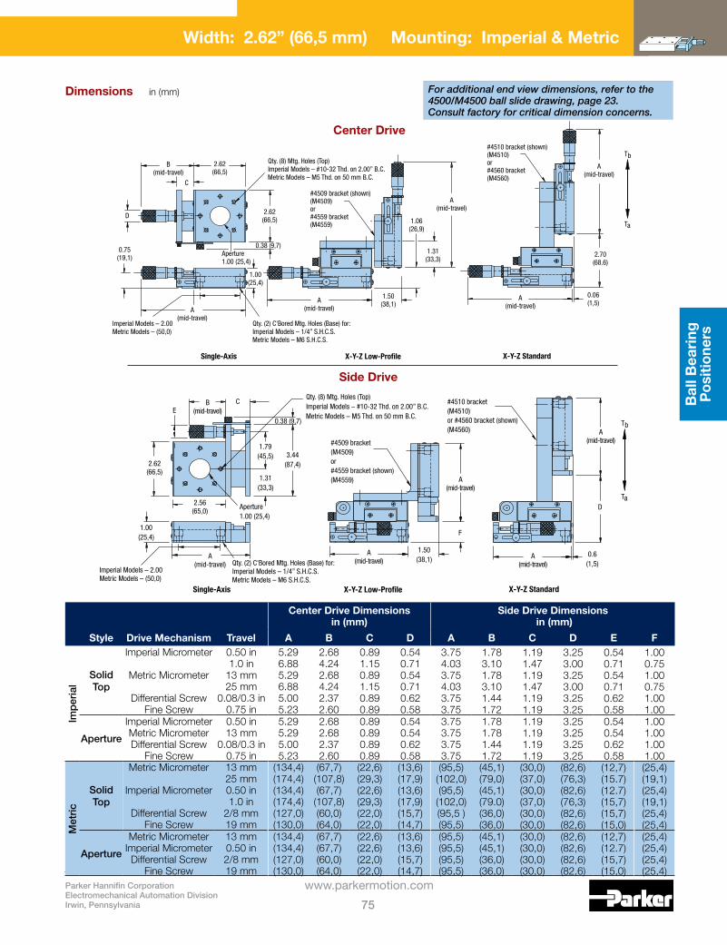
Parker Hannifin CorporationElectromechanical Automation DivisionIrwin, Pennsylvania 75
www.parkermotion.com
Bal
l Bea
ring
P
ositi
oner
s
Center Drive Dimensions in (mm)
Side Drive Dimensions in (mm)
Style Drive Mechanism Travel A B C D A B C D E F
Imp
eria
l
SolidTop
ImperialMicrometer
MetricMicrometer
Differential Screw FineScrew
0.50 in1.0 in
13 mm25 mm
0.08/0.3 in 0.75 in
5.296.885.296.885.005.23
2.684.242.684.242.372.60
0.891.150.891.150.890.89
0.540.710.540.710.620.58
3.754.033.754.033.753.75
1.783.101.783.101.441.72
1.191.471.191.471.191.19
3.253.003.253.003.253.25
0.540.710.540.710.620.58
1.000.751.000.751.001.00
Aperture
ImperialMicrometer MetricMicrometer Differential Screw
FineScrew
0.50 in13 mm
0.08/0.3 in 0.75 in
5.295.295.005.23
2.682.682.372.60
0.890.890.890.89
0.540.540.620.58
3.753.753.753.75
1.781.781.441.72
1.191.191.191.19
3.253.253.253.25
0.540.540.620.58
1.001.001.001.00
Met
ric
SolidTop
MetricMicrometer
ImperialMicrometer
Differential Screw FineScrew
13 mm25 mm 0.50 in1.0 in
2/8 mm 19 mm
(134,4)(174,4)(134,4)(174,4)(127,0)(130,0)
(67,7)(107,8)(67,7)
(107,8)(60,0)(64,0)
(22,6)(29,3)(22,6)(29,3)(22,0)(22,0)
(13,6)(17,9)(13,6)(17,9)(15,7)(14,7)
(95,5)(102,0) (95,5)
(102,0)(95,5 )(95,5)
(45,1)(79,0)(45,1)(79.0)(36,0)(36,0)
(30,0)(37,0)(30,0)(37,0)(30,0)(30,0)
(82,6)(76,3) (82,6)(76,3)(82,6)(82,6)
(12,7)(15.7)(12.7)(15,7)(15,7)(15,0)
(25,4)(19,1)(25,4)(19,1)(25,4)(25,4)
Aperture
MetricMicrometer ImperialMicrometer Differential Screw
FineScrew
13 mm 0.50 in 2/8 mm 19 mm
(134,4)(134,4)(127,0)(130,0)
(67,7)(67,7)(60,0)(64,0)
(22,6)(22,6)(22,0)(22,0)
(13,6)(13,6)(15,7)(14,7)
(95,5)(95,5)(95,5)(95,5)
(45,1)(45,1)(36,0)(36,0)
(30,0)(30,0)(30,0)(30,0)
(82,6)(82,6)(82,6)(82,6)
(12,7)(12.7)(15,7)(15,0)
(25,4)(25,4)(25,4)(25,4)
Side Drive
Center Drive
A(mid-travel)
A(mid-travel)
A(mid-travel)
A(mid-travel)
2.62(66,5)
2.56(65,0)
B(mid-travel)
X-Y-Z StandardX-Y-Z Low-ProfileSingle-Axis
C
DAperture1.00 (25,4)
Ta
Tb
Qty. (8) Mtg. Holes (Top)Imperial Models – #10-32 Thd. on 2.00” B.C.Metric Models – M5 Thd. on 50 mm B.C.
#4510 bracket(M4510)or #4560 bracket (shown)(M4560)
#4509 bracket(M4509)or#4559 bracket (shown)(M4559)
1.50(38,1)
1.31(33,3)
0.6(1,5)
1.79(45,5)
0.38 (9,7)
3.44(87,4)
A(mid-travel)
1.00(25,4)
F
Imperial Models – 2.00Metric Models – (50,0)
Qty. (2) C'Bored Mtg. Holes (Base) for:Imperial Models – 1/4” S.H.C.S.Metric Models – M6 S.H.C.S.
E
A(mid-travel)
A(mid-travel)
A(mid-travel)
A(mid-travel)A
(mid-travel)
Ta
TbQty. (8) Mtg. Holes (Top)Imperial Models – #10-32 Thd. on 2.00” B.C.Metric Models – M5 Thd. on 50 mm B.C.
0.75(19,1)
1.00(25,4)
0.38 (9,7)
1.50(38,1)
1.06(26,9)
1.31(33,3)
2.62(66,5)
2.62(66,5)
2.70(68.6)
0.06(1,5)
B(mid-travel)
D
C
Imperial Models – 2.00Metric Models – (50,0)
#4510 bracket (shown)(M4510)or#4560 bracket(M4560)
#4509 bracket (shown)(M4509)or#4559 bracket(M4559)
Aperture1.00 (25,4)
Qty. (2) C'Bored Mtg. Holes (Base) for:Imperial Models – 1/4” S.H.C.S.Metric Models – M6 S.H.C.S.
X-Y-Z StandardX-Y-Z Low-ProfileSingle-Axis
For additional end view dimensions, refer to the 4500/M4500 ball slide drawing, page 23. Consult factory for critical dimension concerns.
Dimensions in (mm)
Width: 2.62” (66,5 mm) Mounting: Imperial & Metric

Ball Bearing Positioners
Parker Hannifin CorporationElectromechanical Automation Division
Irwin, Pennsylvania76
www.parkermotion.com
Specifications Imperial Metric
Travel: 0.5–1.0in 13–25mm
Size: Width Length(mid-travel) Height
2.62 in 6.50–10.28in 1.00 in
66,5 mm 164,1–261,1mm25,4 mm
Load: Normal Thrust – Ta Thrust – Tb Moment – Yaw, Pitch, Roll
88–123lbs 30 lbs 2 lbs See page 87
40–56kg 13,6 kg 0,9 kg See page 87
Straightlineaccuracy: 0.00008 in/in of travel
2 µm/25 mm of travel
Micrometergraduations: Finescrew:
0.001 in 64 pitch
0,01 mm64 pitch
Weight: 1.1–1.5lbs/axis
0,5–0,7kg/axis
Construction: Aluminumtopandbase/ 440C stainless steel bearings
Mountingsurface: Precision machined
Finish: Black anodize
Width: 2.62” (66,5 mm) Mounting: Imperial & Metric
4600/M4600, 4700/M4700, 4800/M4800 Series

Parker Hannifin CorporationElectromechanical Automation DivisionIrwin, Pennsylvania 77
www.parkermotion.com
Bal
l Bea
ring
P
ositi
oner
s
Drive Mechanism Travel ModelLoadlb (kg)
Weightlb (kg)
Dimensions — in (mm) Qty JA B C D E F G
Imp
eria
l
ImperialMicrometer MetricMicrometer FineScrew
0.50 in1.0 in13 mm25 mm 0.75 in
46024604 4602M4604M4603
88 1.1 4.00
2.68 4.28 2.68 4.28 2.50
0.89 1.18 0.89 1.18 0.88
0.50 —
0.55 0.62 0.55 0.62 0.59
0.69 6
ImperialMicrometer MetricMicrometer FineScrew
0.50 in1.0 in13 mm25 mm 0.75 in
47024704 4702M4704M4703
106 1.2 5.00
2.68 4.28 2.68 4.28 2.50
0.89 1.18 0.89 1.18 0.88
1.00 —
0.55 0.62 0.55 0.62 0.59
1.19 6
ImperialMicrometer MetricMicrometer FineScrew
0.50 in1.0 in13 mm25 mm 0.75 in
48024804 4802M4804M4803
123 1.5 6.00
2.68 4.28 2.68 4.28 2.50
0.89 1.18 0.89 1.18 0.88
0.50 1.00
0.55 0.62 0.55 0.62 0.59
1.69 10
Met
ric
MetricMicrometer ImperialMicrometer FineScrew
13 mm25 mm 0.50 in1.0 in0.75 in
M4602MM4604MM4602M4604M4603
(40) (0,5) (101,6)
(67,7) (108,7) (67,7)
(108,7) (63,5)
(22,6) (29,9) (22,6) (29,9) (22,3)
(12,5) —
(14,0) (15,7) (14,0) (15,7) (15,0)
(12,5) 6
MetricMicrometer ImperialMicrometer FineScrew
13 mm25 mm 0.50 in1.0 in0.75 in
M4702MM4704MM4702M4704 M4703
(48) (0,6) (127,0)
(67,7) (108,7) (67,7)
(108,7) (63,5)
(22,6) (29,9) (22,6) (29,9) (22,3)
(25,0) —
(14,0) (15,7) (14,0) (15,7) (15,0)
(25,0) 6
MetricMicrometer ImperialMicrometer FineScrew
13 mm25 mm 0.50 in1.0 in0.75 in
M4802MM4804MM4802M4804M4803
(56) (0,7) (152,4)
(67,7) (108,7) (67,7)
(108,7) (63,5)
(22,6) (29,9) (22,6) (29,9) (22,3)
(12,5) (25,0)
(14,0) (15,7) (14,0) (15,7) (15,0)
(25,0) 10
2.62(66,5)
Ctr’d
Ctr’dImperial Models – 2.00Metric Models – (50,0)
GG
1.48(37,6)
Base Width
T aT b
B(mid-travel)
0.75(19,1)
1.00(25,4)
1/2 A
A
C
D D EE
F
Imperial Models – 2.00Metric Models – (50,0)
Qty. “J” Mtg. Holes (Top)Imperial Models – #10-32 thd.Metric Models – M5 thd.
Qty. (4) Mtg. Holes (Base)Imperial Models – 1/4” S.H.C.S.Metric Models – M6 S.H.C.S.
For additional end view dimensions, refer to the 4600-4800/M4600-4800 ball slide drawing, page 24. Consult factory for critical dimension concerns.
Dimensions in (mm)
Width: 2.62” (66,5 mm) Mounting: Imperial & Metric

Ball Bearing Positioners
Parker Hannifin CorporationElectromechanical Automation Division
Irwin, Pennsylvania78
www.parkermotion.com
4500-DM/M4500-DM SeriesSpecifications Imperial Metric
Travel: 1.0 in 25 mm
Size: Width Length(mid-travel) Height
2.62 in 8.58 in 1.00 in
66,5 mm 218,0 mm 25,4 mm
Load: Normal Thrust – Ta Thrust – Tb Moment – Yaw, Pitch, Roll
62 lbs 10 lbs 2 lbs See page 87
28 kg 4,5 kg 0,9 kg See page 87
Straightlineaccuracy: 0.00008 in/in of travel
2 µm/25 mm of travel
Micrometergraduations: 0.00005 in 0,001 mm
Weight: 1.4 lbs/axis 0,63 kg/axis
Construction: Aluminumtopandbase/ 440C stainless steel bearings
Mountingsurface: Precision machined
Finish: Black anodize
in/mm
SET
MODEHOLDOFF
0.50000
TaTb
0.38(9,7) 2.62
(66,5)1.15
(29,3)4.81 (122,2)(mid-travel)
1.31(33,3)
1.00(25,4)
Aperture1.00 (25,4)
1.31(33,4)
1.75(44,4)
Imperial Models – 2.00Metric Models – (50,0)
Qty. (8) Mtg. Holes (Top)Imperial Models – #10-32 Thd. on 2.00” B.C.Metric Models – M5 Thd. on 50 mm B.C.
Qty. (2) C'Bored Mtg. Holes (Base) for:Imperial Models – 1/4” S.H.C.S.Metric Models – M6 S.H.C.S.
Style Model
ImperialSolidTop 4504-DM
Aperture(1.0in) 4508-DM
MetricSolidTop M4504-DM
Aperture(25,4mm) M4508-DM
For additional end view dimensions, refer to the 4500/M4500 ball slide drawing, page 23. Consult factory for critical dimension concerns.
Dimensions in (mm)
Width: 2.62” (66,5 mm) Mounting: Imperial & Metric

Parker Hannifin CorporationElectromechanical Automation DivisionIrwin, Pennsylvania 79
www.parkermotion.com
Bal
l Bea
ring
P
ositi
oner
s
Specifications Imperial Metric
Travel: 1.0 in 25 mm
Size: Width Length(mid-travel) Height
2.62 in 9.96–11.96in 1.00 in
66,5 mm 253,1–303,9mm 25,4 mm
Load: Normal Thrust – Ta Thrust – Tb Moment – Yaw, Pitch, Roll
88–123lbs 30 lbs 2 lbs See page 87
40–56kg 13,6 kg 0,9 kg See page 87
Straightlineaccuracy: 0.00008 in/in of travel
2 µm/25 mm of travel
Micrometergraduations: 0.00005 in 0,001 mm
Weight: 1.6–2.0lbs/axis
0,73–0,91kg/axis
Construction: Aluminumtopandbase/ 440C stainless steel bearings
Mountingsurface: Precision machined
Finish: Black anodize
in/mmSET
MODEHOLDOFF
0.50000
Qty. “E” Mtg. Holes (Top)Imperial Models – #10-32 Thd.Metric Models – M5 Thd.
TaTb
1.15(29,3)
0.38(9,7) 4.81 (122,2)
(mid-travel)
1.75(44,4)
2.62(66,5) Ctr’d
Ctr’dImperial Models – 2.00Metric Models – (50,0)
B B
D D
A1/2 A
C C
1.00(25,4)
Imperial Models – 2.00Metric Models – (50,0)
Qty. (4) C'Bored Mtg. Holes (Base) for:Imperial Models – 1/4” S.H.C.S.Metric Models – M6 S.H.C.S.
Model Load Weight
Dimensions — in (mm) QtyEA B C D
Imp
eria
l 4604-DM 88 lbs 1.6 lbs 4.00 0.69 0.50 — 6
4704-DM 106 lbs 1.8 lbs 5.00 1.19 1.00 — 6
4804-DM 123 lbs 2.0 lbs 6.00 1.69 0.50 1.00 10
Met
ric M4604-DM 40 kg 0,73 kg (101,6) (12,5) (12,5) — 6
M4704-DM 48 kg 0,82 kg (127,0) (25,0) (25,0) — 6
M4804-DM 56 kg 0,91 kg (152,4) (25,0) (12,5) (25,0) 10
For additional end view dimensions, refer to the 4600-4800/M4600-4800 ball slide drawing, page 24. Consult factory for critical dimension concerns.
Dimensions in (mm)
Width: 2.62” (66,5 mm) Mounting: Imperial & Metric
4600-DM/M4600-DM, 4700-DM/M4700-DM, 4800-DM/M4800-DM Series

Ball Bearing Positioners
Parker Hannifin CorporationElectromechanical Automation Division
Irwin, Pennsylvania80
www.parkermotion.com
4400/M4400 SeriesSpecifications Imperial Metric
Travel: 1.0–2.0in 25–50mm
Size: Width Length(mid-travel) Height
5.00 in 6.0–11.28in 1.00 in
127,0 mm 152,4–286,0mm 25,4 mm
Load: Normal Thrust – Ta Thrust – Tb Moment – Yaw, Pitch, Roll
105 lbs 30 lbs 2.5 lbs See page 88
48 kg 13,6 kg 1,1 kg See page 88
Straightlineaccuracy: 0.00008 in/in of travel
2 µm/25 mm of travel
Micrometergraduations: 0.001 in 0,01 mm
Weight: 2.7 lbs/axis 1,2 kg/axis
Z-Axisbracketoptions: (Seepage124-127)
4499
M4499
Construction: Aluminumtopandbase/ 440C stainless steel bearings
Mountingsurface: Precision machined
Finish: Black anodize
Style Drive Mechanism Travel
Center Drive Models Side Drive Models
Single Axis
Two Axis Three Axis
Single Axis
Two Axis Three Axis
Imp
eria
l SolidTop
ImperialMicrometer MetricMicrometer
1.0 in2.0 in25 mm50 mm
4411441244134414
4421442244234424
4431443244334434
4416441744184419
4426442744284429
4436443744384439
Aperture (2.0in)
ImperialMicrometer MetricMicrometer
1.0 in2.0 in25 mm50 mm
4451445244534454
4461446244634464
4471447244734474
4456445744584459
4466446744684469
4476447744784479
Met
ric
SolidTop
MetricMicrometer ImperialMicrometer
25 mm 50 mm 1.0 in2.0 in
M4413M4414M4411M4412
M4423M4424M4421M4422
M4433M4434M4431M4432
M4418M4419M4416M4417
M4428M4429M4426M4427
M4438M4439M4436M4437
Aperture (50,8mm)
MetricMicrometer ImperialMicrometer
25 mm 50 mm 1.0 in2.0 in
M4453M4454M4451M4452
M4463M4464M4461M4462
M4473M4474M4471M4472
M4458M4459M4456M4457
M4468M4469M4466M4467
M4478M4479M4476M4477
Width: 5.00” (127,0 mm) Mounting: Imperial & Metric
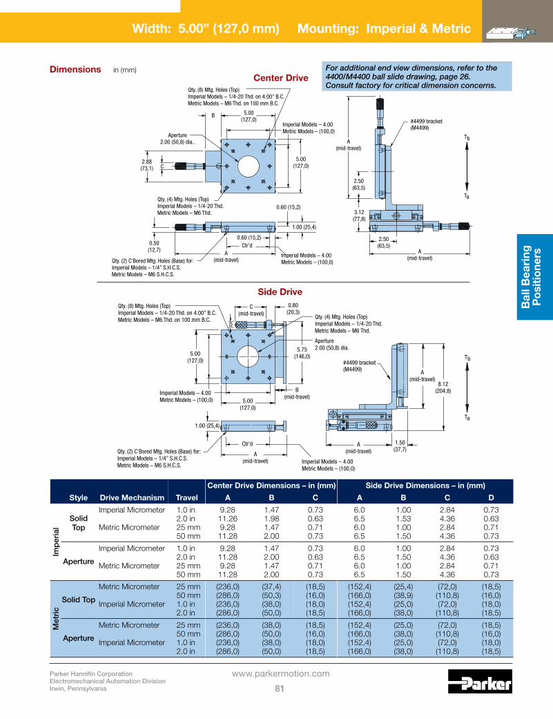
Parker Hannifin CorporationElectromechanical Automation DivisionIrwin, Pennsylvania 81
www.parkermotion.com
Bal
l Bea
ring
P
ositi
oner
s
Center Drive Dimensions – in (mm) Side Drive Dimensions – in (mm)
Style Drive Mechanism Travel A B C A B C D
Imp
eria
l
Solid Top
ImperialMicrometer MetricMicrometer
1.0 in2.0 in25 mm50 mm
9.2811.269.28
11.28
1.471.981.472.00
0.730.630.710.73
6.06.56.06.5
1.001.531.001.50
2.844.362.844.36
0.730.630.710.73
Aperture
ImperialMicrometer MetricMicrometer
1.0 in2.0 in25 mm50 mm
9.2811.289.28
11.28
1.472.001.472.00
0.730.630.710.73
6.06.56.06.5
1.001.501.001.50
2.844.362.844.36
0.730.630.710.73
Met
ric
SolidTop
MetricMicrometer ImperialMicrometer
25 mm 50 mm 1.0 in2.0 in
(236,0)(286,0)(236,0)(286,0)
(37,4)(50,3)(38,0)(50,0)
(18,5)(16,0)(18,0)(18,5)
(152,4)(166,0) (152,4)(166,0)
(25,4)(38,9)(25,0)(38,0)
(72,0)(110,8)(72,0)
(110,8)
(18,5)(16,0)(18,0)(18,5)
Aperture
MetricMicrometer ImperialMicrometer
25 mm 50 mm 1.0 in2.0 in
(236,0)(286,0)(236,0)(286,0)
(38,0)(50,0)(38,0)(50,0)
(18,5)(16,0)(18,0)(18,5)
(152,4)(166,0) (152,4)(166,0)
(25,0)(38,0)(25,0)(38,0)
(72,0)(110,8)(72,0)
(110,8)
(18,5)(16,0)(18,0)(18,5)
Side Drive
Center Drive
Ta
Tb
Imperial Models – 4.00Metric Models – (100,0)
Qty. (2) C'Bored Mtg. Holes (Base) for:Imperial Models – 1/4” S.H.C.S.Metric Models – M6 S.H.C.S.
Ctr’d
A(mid-travel)
B(mid-travel)
A(mid-travel)
A(mid-travel)
#4499 bracket(M4499)
5.00(127,0)
5.00(127,0)
1.00 (25,4)
8.12(204,8)
1.50(37,7)
0.80(20,3)
5.75(146,0)
C(mid-travel)
D
Imperial Models – 4.00Metric Models – (100,0)
Qty. (8) Mtg. Holes (Top)Imperial Models – 1/4-20 Thd. on 4.00” B.C.Metric Models – M6 Thd. on 100 mm B.C. Qty. (4) Mtg. Holes (Top)
Imperial Models – 1/4-20 Thd.Metric Models – M6 Thd.
Aperture2.00 (50,8) dia.
Imperial Models – 4.00Metric Models – (100,0)
Imperial Models – 4.00Metric Models – (100,0)
Aperture2.00 (50,8) dia..
B 5.00(127,0)
5.00(127,0)
Qty. (8) Mtg. Holes (Top)Imperial Models – 1/4-20 Thd. on 4.00” B.C.Metric Models – M6 Thd. on 100 mm B.C.
Qty. (4) Mtg. Holes (Top)Imperial Models – 1/4-20 Thd.Metric Models – M6 Thd.
Qty. (2) C'Bored Mtg. Holes (Base) for:Imperial Models – 1/4” S.H.C.S.Metric Models – M6 S.H.C.S.
A(mid-travel)
A(mid-travel)
A(mid-travel)
Ctr’d
2.88(73,1) C
1.00 (25,4)
0.60 (15,2)
0.60 (15,2)0.50
(12,7)
2.50(63,5)
3.12(77,8)
2.50(63,5)
#4499 bracket(M4499)
Ta
Tb
For additional end view dimensions, refer to the 4400/M4400 ball slide drawing, page 26. Consult factory for critical dimension concerns.
Dimensions in (mm)
Width: 5.00” (127,0 mm) Mounting: Imperial & Metric

Ball Bearing Positioners
Parker Hannifin CorporationElectromechanical Automation Division
Irwin, Pennsylvania82
www.parkermotion.com
4400-DM/M4400-DM SeriesSpecifications Imperial Metric
Travel: 1.0–2.0in 25–50mm
Size: Width Length(mid-travel) 1.0”(25mm)2.0”(50mm) Height
5.00 in
11.28 in14.16 in 1.00 in
127,0 mm
286.5 mm 542.1 mm25,4 mm
Load: Normal Thrust – Ta Thrust – Tb Moment – Yaw, Pitch, Roll
105 lbs 30 lbs 2.0 lbs See page 88
48 kg 13,6 kg 0,9 kg See page 88
Straightlineaccuracy: 0.00008 in/in of travel
2 µm/25 mm of travel
Micrometergraduations: 0.00005 in 0,001 mm
Weight: 3.1 lbs/axis 1,4 kg/axis
Construction: Aluminumtopandbase/ 440C stainless steel bearings
Mountingsurface: Precision machined
Finish: Black anodize
Style Model Travel
Imperial
SolidTop4410-DM 1.0 in
4412-DM 2.0 in
Aperture(1.0in)4450-DM 1.0 in
4452-DM 2.0 in
Metric
SolidTopM4410-DM 25 mm
M4412-DM 50 mm
Aperture(25,4mm)M4450-DM 25 mm
M4452-DM 50 mm
Width: 5.00” (127,0 mm) Mounting: Imperial & Metric

Parker Hannifin CorporationElectromechanical Automation DivisionIrwin, Pennsylvania 83
www.parkermotion.com
Bal
l Bea
ring
P
ositi
oner
s
2.0 in (50 mm) Travel Models
1.0 in (25 mm) Travel Models
in/mmSET
MODEHOLDOFF
0.50000
5.00(127,0)
Ctr’d
Ctr’d
5.00(127,0)
1.47(37,3)
4.81 (122,2)(mid-travel)
Ta Tb
Imperial Models – 4.00Metric Models – (100,0)
Imperial Models – 4.00Metric Models – (100,0)
Imperial Models – 0.50Metric Models – (13,5)
Qty. (8) Mtg. Holes (Top)Imperial Models – 1/4-20 Thd. on 4.00” B.C.Metric Models – M6 Thd. on 100 mm B.C.
Qty. (4) Mtg. Holes (Top)Imperial Models – 1/4-20 Thd. on 4.00” B.CMetric Models – M6 Thd. on 100 mm B.C.
0.74(18,8)
Aperture2.00 (50,8) dia.
Qty. (2) C'Bored Mtg. Holes (Base) for:Imperial Models – 1/4” S.H.C.S.Metric Models – M6 S.H.C.S.
1.00(25,4) 0.60
(15,2)
For additional end view dimensions, refer to the 4400/M4400 ball slide drawing, page 26. Consult factory for critical dimension concerns.
in/mmSET
MODEHOLDOFF
0.50000
5.00(127,0)
Ctr’d
Ctr’d
5.00(127,0)
1.98(50,3)
7.18 (182,4)(mid-travel)
Ta Tb
Imperial Models – 4.00Metric Models – (100,0)
Imperial Models – 4.00Metric Models – (100,0)
Imperial Models – 0.50Metric Models – (13,5)
Qty. (8) Mtg. Holes (Top)Imperial Models – 1/4-20 Thd. on 4.00” B.C.Metric Models – M6 Thd. on 100 mm B.C.
Qty. (4) Mtg. Holes (Top)Imperial Models – 1/4-20 Thd. on 4.00” B.CMetric Models – M6 Thd. on 100 mm B.C.
0.74(18,8)
Aperture2.00 (50,8) dia.
Qty. (2) C'Bored Mtg. Holes (Base) for:Imperial Models – 1/4” S.H.C.S.Metric Models – M6 S.H.C.S.
1.00(25,4) 0.60
(15,2)
Dimensions in (mm)
Width: 5.00” (127,0 mm) Mounting: Imperial & Metric

Ball Bearing Positioners
Parker Hannifin CorporationElectromechanical Automation Division
Irwin, Pennsylvania84
www.parkermotion.com
Imperial Models – 2.50Metric Models – (62,5)
Imperial Models – 0.50Metric Models – (13,7)
0.50(12,7)
0.50(12,7)
1.0 (25 mm) Travel Models: 0.63 (16,0)2.0 (50 mm) Travel Models: 0.73 (18,5)
0.75(19,0)
1.06(26,9)
6.00(152,4)
6.00(152,4)
Ctr’d
Imperial Models – 5.00Metric Models – (125,0)
Ctr’dImperial Models – 5.00Metric Models – (125,0)
Ctr’dImperial Models – 5.00Metric Models – (125,0)
TaTb
Qty. (6) Mtg. Holes (Top)Imperial Models – 1/4-20 Thd.Metric Models – M6 Thd.
A(mid-travel)
2.06(52,0)
0.75(19,0)
A(mid-travel)
2.00(50,8)
4.00 x 0.01(101,6 x 0,25)Relief Depth
Ctr’dImperial Models – 5.00Metric Models – (125,0)
4.00 x 0.01(101,6 x 0,25)Relief Depth
Qty. “(4) C'Bored Mtg. Holes (Base) for:Imperial Models – 1/4” S.H.C.S.Metric Models – M6 S.H.C.S.
Standard Thimble Large Thimble
1.69(43,0)
1.69(43,0)
4900/M4900 SeriesSpecifications Imperial Metric
Travel: 1.0–2.0in 25–50mm
Size: Width Length(mid-travel) Height
6.00 in 9.59–11.11in 2.00 in
152,4 mm 243,6–282,2mm50,8 mm
Load: Normal Thrust Ta(Std.thimble) Thrust – Tb(Std.thimble) Thrust Ta(Std.thimble) Thrust – Tb(Std.thimble) Moment – Yaw, Pitch, Roll
100 lbs 30 lbs 3.0 lbs 50 lbs 3.0 lbs See page 88
45 kg 13,6 kg 1,36 kg 23,0 kg 1,36 kg See page 88
Straightlineaccuracy: 0.00008 in/in of travel
2 µm/25 mm of travel
Micrometergraduations: Standardthimble Largethimble
0.001 in 0.0001 in
0,01 mm 0,001 mm
Weight: 7 lbs/axis 1,4 kg/axis
Construction: Aluminumtopandbase/ 440C stainless steel bearings
Mountingsurface: Precision machined
Finish: Black anodize
Standard Thimble Large Thimble
Drive Mechanism Travel Model* Dimension A – in (mm) Model* Dimension A – in (mm)
Imp
eria
l
ImperialMicrometer 1.0 in2.0 in
49144915
3.595.11
49104911
4.445.94
MetricMicrometer 25 mm50 mm
49164917
3.595.11
49124913
4.445.94
Met
ric MetricMicrometer 25 mm
50 mmM4916M4917
(91,2)(1289,8)
M4912M4913
(112.8)(150,9)
ImperialMicrometer 1.0 in2.0 in
M4914M4915
(91,2)(129,8)
M4910M4911
(112.8)(150,9)
*Add-Ltomodelnumberforoptionalpositionlock.
Consult factory for critical dimension concerns.
Large thimble (left) and standard thimble with optional position lock (right). To order the optional lock, add -L to the model number selected from the chart below.
Dimensions in (mm)
Width: 6.00” (152,4 mm) Mounting: Imperial & Metric

Parker Hannifin CorporationElectromechanical Automation DivisionIrwin, Pennsylvania 85
www.parkermotion.com
Bal
l Bea
ring
P
ositi
oner
s
4900-DM/M4900-DM SeriesSpecifications Imperial Metric
Travel: 2.0 in 50 mm
Size: Width Length(mid-travel) Height
6.00 in 13.93 in 2.00 in
152,4 mm 353,8 mm 50,8 mm
Load: Normal Thrust Ta Thrust – Tb Moment – Yaw, Pitch, Roll
100 lbs 50 lbs 3.0 lbs See page 88
45 kg 23,0 kg 1,36 kg See page 88
Straightlineaccuracy: 0.00008 in/in of travel
2 µm/25 mm of travel
Micrometergraduations: Largethimble
0.0001 in
0,001 mm
Weight: 7 lbs/axis 3,2 kg/axis
Z-Axisbracketoptions: (Seepage124-127)
4990-04
M4990-04
Construction: Aluminumtopandbase/ 440C stainless steel bearings
Mountingsurface: Precision machined
Finish: Black anodize
Model*
Imperial 4911-DM
Metric M4911-DM
Consult factory for critical dimension concerns.
Digital micrometer positioner shown with optional position lock. To order the optional lock, add -L to the model number selected from the chart below.
6.00(152,4)
Ctr’dImperial Models – 5.00Metric Models – (125,0)
Imperial Models – 5.00Metric Models – (125,0)
Ctr’d
2.00(50,8)
Qty. (4) C'Bored Mtg. Holes (Base) for:Imperial Models – 1/4” S.H.C.S.Metric Models – M6 S.H.C.S.
Imperial Models – 2.50Metric Models – (62,5)
Imperial Models – 0.50Metric Models – (13,7)
6.00(152,4)
Ctr’dImperial Models – 5.00Metric Models – (125,0)
0.50(12,7)
1.69(43,0)
4.00 x 0.01(101,6 x 0,25)Relief Depth
Qty. (6) Mtg. Holes (Top)Imperial Models – 1/4-20 Thd.Metric Models – M6 Thd.0.75
(19,0)
7.93 (201,4)(mid-travel)
Dimensions in (mm)
Width: 6.00” (152,4 mm) Mounting: Imperial & Metric
*Add-Ltomodelnumberforoptional position lock.

Ball Bearing Positioners
Parker Hannifin CorporationElectromechanical Automation Division
Irwin, Pennsylvania86
www.parkermotion.com
No Readout Model*
Imperial Readout Model*
Metric Readout Model*
Travelin (mm)
Loadlbs (kg)
Weightlbs (kg)
Dimensions – in (mm) Qty F
Qty GA B C D E
Imp
eria
l 4945-04 4955-04 4965-04 4.0 100 4.0 6.00 5.00 — — — 6 44945-06 4955-06 4965-06 6.0 154 6.0 9.00 5.00 1.50 1.50 — 10 84945-08 4955-08 4965-08 8.0 205 8.0 12.00 5.00 3.00 2.50 — 10 84945-10 4955-10 4965-10 10.0 243 10.0 15.00 6.00 4.00 2.50 2.00 14 84945-12 4955-12 4965-12 12.0 294 12.0 18.00 7.00 5.00 5.00 1.00 14 8
Met
ric
M4945-04 M4955-04 M4965-04 (100,0) (45) (1,8) (152,4) (125,0) — — — 6 4M4945-06 M4955-06 M4965-06 (150,0) (70) (2,7) (228,6) (125,0) (37,5) (37,5) — 10 8M4945-08 M4955-08 M4965-08 (200,0) (93) (3,6) (304,8) (125,0) (75,0) (62,5) — 10 8M4945-10 M4955-10 M4965-10 (250,0) (110) (4,5) (381,0) (150,0) (100,0) (62,5) (50,0) 14 8M4945-12 M4955-12 M4965-12 (300,0) (133) (5,4) (457,2) (175,0) (125,0) (125,0) (25,0) 14 8
4900/M4900 SeriesSpecifications Imperial Metric
Travel: 4.0–12.0in 100,0–300,0mm
Size: Width Length Height
6.00 in 9.39–in 2.00 in
152,4 mm mm 50,8 mm
Load: Normal Thrust Ta Thrust – Tb Moment – Yaw, Pitch, Roll
100–294lbs 30 lbs 30 lbs See page 88
45–133kg 13,6 kg 13,6 kg See page 88
Straightlineaccuracy: 0.00008 in/in of travel
2 µm/25 mm of travel
Readoutgraduations: 0.001 in 0,01 mm
Weight: 4–12lbs/axis 1,8–5,4kg/axis
Z-Axisbracketoptions: (Seepage124-127)
4990-04/-12
M4990-04/-12
Construction: Aluminumtopandbase/ 440C stainless steel bearings
Mountingsurface: Precision machined
Finish: Black anodize
BCtr’d
C C
Imperial Models – 5.00Metric Models – (125,0)
2.00(50,8)
With Readout Models:4955, 4965
M4955, M4965
No Readout Models:4945
M4945
Qty. “F” Mtg. Holes (Top)Imperial Models – 1/4-20 Thd.Metric Models – M6 Thd.
Qty. “G” C'Bored Mtg. Holes (Base) for:Imperial Models – 1/4” S.H.C.S.Metric Models – M6 S.H.C.S.
A(top & base lgth)
D ED
1/2 A
6.00(152,4)
Imperial Models – 5.00Metric Models – (125,0)
E
Imperial Models – 2.50Metric Models – (62,5)
TaTb
3.39(86.1)
2.00(50.8)
dia. typ.
6.00 (152.3)
0.97(24.6)
1.90(48.3)
1.69(43.0)
1.69(43.0)
3.25(82.5)
4.00 x 0.01(101,6 x 0,25)Relief Depth
Consult factory for critical dimension concerns.
Leadscrew drive positioner with readout (left); positioner with no readout and optional position lock (right). To order the optional lock, add -L to the model number selected from the chart below.
Dimensions in (mm)
*Add-Ltomodelnumberforoptionalpositionlock.
Width: 6.00” (152,4 mm) Mounting: Imperial & Metric
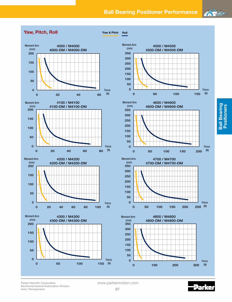
Parker Hannifin CorporationElectromechanical Automation DivisionIrwin, Pennsylvania 87
www.parkermotion.com
Bal
l Bea
ring
P
ositi
oner
s
Yaw
Pitch
Roll
Ball Bearing Positioner Performance
Yaw, Pitch, Roll Yaw & Pitch Roll
Force (N)
Force (N)
Force (N)
Force (N)
Moment Arm (mm)
Moment Arm (mm)
Moment Arm (mm)
Moment Arm (mm)
Moment Arm (mm)
Force (N)
4000 / M40004000-DM / M4000-DM
4100 / M41004100-DM / M4100-DM
4200 / M42004200-DM / M4200-DM
4300 / M43004300-DM / M4300-DM
4500 / M45004500-DM / M4500-DM
4600 / M46004600-DM / M4600-DM
4700 / M47004700-DM / M4700-DM
4800 / M48004800-DM / M4800-DM
0
50
100
150
200
0 20 40 60
0
50
100
150
200
0 20 40 60 80
0
50
100
150
200
0 20 40 60 80 100
0
50
100
150
200
0 50 100 150
0
50
100
150
200
250
300
350
0 50 100 150
Force (N)
Moment Arm (mm)
Moment Arm (mm)
Force (N)
0
50
100
150
200
250
300
350
0 50 100 150 200 250
0
50
100
150
200
250
300
350
0 100 200 300
Moment Arm (mm)
Force (N)
0
50
100
150
200
250
300
350
0 50 100 150 200

Ball Bearing Positioners
Parker Hannifin CorporationElectromechanical Automation Division
Irwin, Pennsylvania88
www.parkermotion.com
Yaw, Pitch, Roll
Ball Bearing Positioner Performance
Yaw & Pitch Roll
Force (N)
Moment Arm (mm)
0100200300400500600700800
0 50 100 150 200 250
Moment Arm (mm)
Force (N)
3900 / M3900
4400 / M44004400-DM / M4400-DM
4910-4917 / M4910-M49174911-DM / M4911-DM
4945-04 / M4945-044955-04 / M4955-044965-04 / M4965-04
4945-12 / M4945-124955-12 / M4955-124965-12 / M4965-12
4945-10 / M4945-104955-10 / M4955-104965-10 / M4965-10
4945-08 / M4945-084955-08 / M4955-084965-08 / M4965-08
4945-06 / M4945-064955-06 / M4955-064965-06 / M4965-06
0
20
40
60
80
100
120
140
0 5 10 15
Moment Arm (mm)
Force (N)
0
100
200
300
400
500
600
700
0 50 100 150 200
Force (N)
Moment Arm (mm)
0100200300400500600700800900
0 100 200 300
Force (N)
Force (N)
Moment Arm (mm)
Moment Arm (mm)
0100200300400500600700800900
0 100 200 300 400
0100200300400500600700800900
0 200 400 600 800
Force (N)
Moment Arm (mm)
Moment Arm (mm)
Force (N)
0100200300400500600700800900
0 200 400 600
0100200300400500600700800900
0 200 400 600 800

Contents90-91 Overview
92-96 1.75” (44,5 mm) Wide
97 1.97” (50,0 mm) Wide
98-101 2.62” (66,5 mm) Wide
102 2.95” (75,0 mm) Wide
103 3.94” (100,0 mm) Wide
104-107 5.00” (127,0 mm) Wide
108-110 6.00” (152,4 mm) Wide
111-114 Performance Curves
89
Parker Daedal precision crossed roller stages provide controlled, precise
point-to-point positioning along a linear axis. Stages are comprised
of two basic components: a precision linear crossed roller slide
which serves as a linear bearing and guide, and a drive mechanism
which accurately moves and positions the slide top along the linear
axis. Crossed roller positioning stages offer exceptional load carrying
capability, approximately 2 to 2 1/2 times that of comparably sized ball
bearing stages. Additionally, crossed roller stages provide up to five
times the life expectancy of the ball bearing stages without degradation
of performance. Parker Daedal crossed roller stages are rated for over
100 million inches of travel at specified load.
Crossed Roller Bearing Positioners

Crossed Roller Positioners
Parker Hannifin CorporationElectromechanical Automation Division
Irwin, Pennsylvania90
www.parkermotion.com
Crossed Roller Bearing Positioners• PrecisionQuality• BudgetFriendly• LargestSelection• Easymulti-axisconfiguration• Nomaintenance• Vacuumpreparationandcustomoptions
Features and Overview
Crossed Roller Positioner Design PrinciplesCrossed roller positioning stages offer exceptional load carrying capability, approximately 2 to 2 1/2 times that of comparably sized ball bearing stages. Additionally, crossed roller stages provide up to five times the life expectancy of the ball bearing stages without degradation of performance. Parker Daedal crossed roller stages are rated for over 100 million inches of travel at specified load. Three types of drive mechanisms are available: a fine screw, a micrometer, and a differential screw. The fine screw is used for fine resolution positioning. The micrometer is used whenever a position readout is required. The differential screw is used for applications requiring extremely fine resolution positioning. Crossed roller positioning stages are available in a straight stage/drive configuration as well as a side-drive configuration.
The linear positioner operates in a simple manner: a bracket which supports the drive screw is attached to the slide base. The end of the drive screw rests against the end of the moveable top. There are two extended springs “pulling” the slide top toward the screw so that the top will always be held firmly against the screw end. When the screw is turned clockwise, it advances and pushes the slide top along the linear axis. When turned counter clockwise, the screw retracts and the slide top follows because of the spring pressure holding the top against the screw end. The result is a very smooth linear motion, accurately controlled by rotation of the drive mechanism.
Standard FeaturesExacting manufacturing techniques, combined with demanding quality control standards, permit Parker Daedal to offer precision stages of unsurpassed quality. Selection can be made easily, based on required travel, load, and mounting surface requirements. Stages are available in single or multi-axis configurations (XY, XZ, and XYZ), and all have built-in quality features including:
• Aluminum/steelconstruction• Low friction linear adjustment with no backlash or side play• Factorypreloadedtoprovidedynamicstabilityand
minimum runout• Bothtopandbottommountingsurfacesareprecision
machined to provide micro-flat mounting surfaces• Lockingscrewtopositivelylockstagewithoutaffecting
position • Straightlineaccuracyof0.00008in/inoftravel• Selectabledrivemechanisms:Micrometer(Imperialor
metric),Finescrew(64pitch),Differentialscrew,Digitalmicrometers(ImperialandMetric)
Digital MicrometersThe 1.0” (25 mm) travel micrometer provides an LCD readout to 0.00005 in (0,001 mm) resolution and features incremental and/or absolute positioning modes and automatic shutdown to conserve the integral battery. The battery will power the unit for 500 hours of use. The 2.0” (51 mm) micrometer is accurate to ±0.0001 in (±2 microns) with a resolution and LCD reading to 0.00005 in (1 micron). The batteries will power the unit up to 5,000 hours.
How to OrderUse the overview chart on the following page to select the appropriate crossed roller positioner. Refer to the individual specifications page for complete performance and mechanical specifications. To order crossed roller bearing positioners, use the model number corresponding to the specific size and travel length selected. A variety of modifications to standard models are available to meet custom requirements. Contact our application engineering department with your design specifications.

Parker Hannifin CorporationElectromechanical Automation DivisionIrwin, Pennsylvania 91
www.parkermotion.com
Cro
ssed
Ro
ller
Pos
ition
ers
Features and Overview
Hardened and precision machined crossed rollers and ways
Hardened and machined preloaded gib
Steel locking inserts for preload
Steel threaded insertsPrecision machined
aluminum top and base with black anodized finish
Series
Widthin (mm)
Travel Normal Load Drive Orientation Mounting
Pagein (mm) lbs (kg) Center Side Imperial Metric
CR4000CR4100CR4200CR4300
1.75(44,5) 1.00 (25,4)
8181
121131
(37)(37) (55) (59)
•• ••
•
•• ••
92-94 95-96 95-96 95-96
SC050SK050
1.97 (50,0)
0.981.972.95
(25)(50)(75)
175263351
(80)(119)(159)
• • •
• • •
97
CR4500CR4600CR4700CR4800
2.62(66,5) 1.00 (25,4)
111151201251
(50)(69) (91)
(114)
• • • •
•
• • • •
98-99,101 100-101 100-101 100-101
SC075SK075
2.95(75,0)
0.981.972.95
(25)(50)(75)
351439527
(159)(199)(239)
• • •
• • •
102
SC100SK100
3.94(100.0)
0.981.972.953.94
(25)(50)(75)
(100)
439527614702
(199)(239)(278)(318)
• • • •
• • • •
103
CR4400 5.0(127,0)
1.002.00
(25,4)(50,8)
201201
(91)(91)
••
••
••
104-107104-107
CR4900 6.0(152,4)
1.002.004.006.008.00
10.0012.00
(50,8)(50,8)
(100,0)(150,0)(200,0)(250,0)(300,0)
423423423719
105213951735
(192)(192)(192)(326)(477)(633)(786)
•••••••
•••••••
108-109108-109
110110 110110110
Wide selection of drive mechanisms

Crossed Roller Positioners
Parker Hannifin CorporationElectromechanical Automation Division
Irwin, Pennsylvania92
www.parkermotion.com
CR4000 SeriesSpecifications
Travel: 0.5 in
Size: Width Length(mid-travel) Height
1.75 in 2.95 – 4.47 in 1.00 in
Load: Normal Thrust – Ta Thrust – Tb Moment – Yaw, Pitch, Roll
81lbs 10 lbs 5 lbs See page 111
Straightlineaccuracy: 0.00008in/inoftravel
Micrometergraduations: Differential screw: CoarseAdjustment FineAdjustment
0.001 in or 0,01 mm 48pitch336 pitch
Weight: 0.5 lbs/axis
Z-Axisbracketoptions: (Seepage124-127) Centerdrivelowprofile Centerdrivestandard Sidedrivelowprofile Sidedrivestandard
4009 40104059 4060
Construction: Aluminum top and base/ steel crossed roller bearings
Mountingsurface: Precision machined
Finish: Blackanodize
Width: 1.75” (44,5 mm) Mounting: Imperial
Drive Mechanism Travel
Center Drive Models Side Drive Models
Single Axis
Two Axis
X-Y-Z Low Profile
X-Y-Z Standard
Single Axis
Two Axis
X-Y-Z Low Profile
X-Y-Z Standard
ImperialMicrometer MetricMicrometer Differential Screw
0.50 in13 mm 2/8mm
CR4002 CR4002M CR4002D
CR4022 CR4022M CR4022D
CR4032 CR4032M CR4032D
CR4042 CR4042M CR4042D
CR4052 CR4052M CR4052D
CR4072 CR4072M CR4072D
CR4082 CR4082M CR4082D
CR4092 CR4092M CR4092D

Parker Hannifin CorporationElectromechanical Automation DivisionIrwin, Pennsylvania 93
www.parkermotion.com
Cro
ssed
Ro
ller
Pos
ition
ers
Center Drive Dimensions – in Side Drive Dimensions – inDrive Mechanism Travel A B C D A B C D
ImperialMicrometer MetricMicrometer Differential Screw
0.50 in13 mm 2/8mm
4.474.374.13
2.722.682.38
0.950.950.95
0.540.540.62
2.952.952.95
1.771.781.44
1.201.191.20
0.540.540.62
Dimensions Inches
Side Drive
Center Drive
1.12
1.121.12
0.87
2.30
#4059 bracket
#4060 bracket
X-Y-Z StandardX-Y-Z Low-ProfileSingle-Axis
Ta
Tb
Qty. (2) C'Bored Mtg. Holes (Base) for #6-32 S.H.C.S.
B(mid-travel)
C
D
1.00Ctr’d
1.00
1.00Ctr’d
1.75
1.75
0.88
1.292.50
Qty. (4) Mtg. Holes (Top)#6-32 Thd.
Qty. (4) Mtg. Holes (Top)#6-32 Thd. on 1.12 B.C.
0.38
A(mid-travel)
A(mid-travel)
A(mid-travel)
A(mid-travel)
A(mid-travel)
D
1.32
1.38
2.38
0.37
#4009 bracket
#4010 bracket
A(mid-travel)
A(mid-travel)
A(mid-travel)
A(mid-travel)
A(mid-travel)
B(mid-travel)
C0.38
1.75
1.75
1.00
1.12Ctr’d
1.00Ctr’d
1.00Ctr’d
Qty. (2) C'Bored Mtg. Holes (Base) for #6-32 S.H.C.S.
Qty. (4) Mtg. Holes (Top)#6-32 Thd.
Qty. (4) Mtg. Holes (Top)#6-32 Thd. on 1.12” B.C.
Ta
Tb
X-Y-Z StandardX-Y-Z Low-ProfileSingle-Axis
For additional end view dimensions, refer to the CR4000 crossed roller slide drawing, page 40. Consult factory for critical dimension concerns.
Width: 1.75” (44,5 mm) Mounting: Imperial

Crossed Roller Positioners
Parker Hannifin CorporationElectromechanical Automation Division
Irwin, Pennsylvania94
www.parkermotion.com
Dimensions Inches
CR4000-DM SeriesSpecifications
Travel: 1.0 in
Size: Width Length(mid-travel) Height
1.75 in 7.75 in 1.00 in
Load: Normal Thrust – Ta Thrust – Tb Moment – Yaw, Pitch, Roll
81lbs 10 lbs 3 lbs See page 111
Straightlineaccuracy: 0.00008in/inoftravel
Micrometergraduations: 0.00005 in
Weight: 0.8lbs
Construction: Aluminum top and base/ 440C stainless steel bearings
Mountingsurface: Precision machined
Finish: Blackanodize
Model
ImperialMounting CR4002-DM
0.50000
OFF HOLD MODE
SET
in/mm
1.00Ctr’d
1.00Ctr’d
Qty. (4) Mtg. Holes (Top)#6-32 Thd.
0.32
1.75
0.38
1.75
0.875
1.75 1.18 4.81(mid-travel)
Qty. (4) Mtg. Holes (Top)#6-32 Thd. on 1.12” B.C.
1.13Ctr’d
Qty. (2) C'Bored Mtg. Holes (Base) for #6-32 S.H.C.S.
0.501.00
TaTb
For additional end view dimensions, refer to the CR4000 crossed roller slide drawing, page 40. Consult factory for critical dimension concerns.
Width: 1.75” (44,5 mm) Mounting: Imperial

Parker Hannifin CorporationElectromechanical Automation DivisionIrwin, Pennsylvania 95
www.parkermotion.com
Cro
ssed
Ro
ller
Pos
ition
ers
CR4100, CR4200, CR4300 SeriesSpecifications
Travel: 0.5 – 1.0 in
Size: Width Length(mid-travel) Height
1.75 in 4.6–8.28in 0.75 in
Load: Normal Thrust – Ta Thrust – Tb Moment – Yaw, Pitch, Roll
81-131lbs 10 lbs 3 lbs See page 111
Straightlineaccuracy: 0.00008in/inoftravel
Micrometergraduations:Finescrew:
0.001 in or 0,01 mm64 pitch
Weight: 0.8–1.3lbs/axis
Construction: Aluminum top and base/ steel crossed roller bearings
Mountingsurface: Precision machined
Finish: Blackanodize
Dimensions Inches
1.00Ctr’d
1.75
0.25
0.50 typ.
0.50
0.75 0.31 D
AC
E
0.38
1.00
TaTb
Qty. “F” Mtg. Holes (Top)#6-32 Thd.
B(mid-travel)
1.75
Qty. (2) C'Bored Mtg. Holes (Base) for #6-32 S.H.C.S.
Drive Mechanism Travel Model Load Weight
Dimensions - in Qty FA B C D E
ImperialMicrometer MetricMicrometer FineScrew
0.50 in1.0 in13 mm25 mm 0.75 in
CR4102CR4104 CR4102MCR4104MCR4103
81lbs 0.5 lbs 2.00
2.72 4.28 2.72 4.28 2.50
0.94 1.18 0.94 1.18 0.94
1.38
0.55 0.71 0.55 0.71 0.58
8
ImperialMicrometer MetricMicrometer FineScrew
0.50 in1.0 in13 mm25 mm 0.75 in
CR4202CR4204 CR4202MCR4204MCR4203
121 lbs 0.8lbs 3.00
2.72 4.28 2.72 4.28 2.50
0.941.18 0.94 1.18 0.94
2.38
0.55 0.71 0.55 0.71 0.58
12
ImperialMicrometer MetricMicrometer FineScrew
0.50 in1.0 in13 mm25 mm 0.75 in
CR4302CR4304 CR4302MCR4304MCR4303
131 lbs 1.0 lbs 4.00
2.72 4.28 2.72 4.28 2.50
0.94 1.18 0.94 1.18 0.94
3.38
0.55 0.71 0.55 0.71 0.58
16
Consult factory for critical dimension concerns.
Width: 1.75” (44,5 mm) Mounting: Imperial

Crossed Roller Positioners
Parker Hannifin CorporationElectromechanical Automation Division
Irwin, Pennsylvania96
www.parkermotion.com
Dimensions Inches
CR4100-DM, CR4200-DM, CR4300-DM SeriesSpecifications
Travel: 1.0 in
Size: Width Length(mid-travel) Height
1.75 in 7.99 – 9.99 in 1.00 in
Load: Normal Thrust – Ta Thrust – Tb Moment – Yaw, Pitch, Roll
81–131lbs 10 lbs 3 lbs See page 111
Straightlineaccuracy: 0.00008in/inoftravel
Micrometergraduations: 0.00005 in
Weight: 0.9 – 1.3 lbs/axis
Construction: Aluminum top and base/ 440C stainless steel bearings
Mountingsurface: Precision machined
Finish: Blackanodize
ModelNormal Load Weight
Dimensions – in
A B C
CR4104-DM 81lbs 1.0 lbs 2.00 1.38 8
CR4204-DM 121 lbs 1.1 lbs 3.00 2.38 12
CR4304-DM 131 lbs 1.3 lbs 4.00 3.38 16
0.31
1.00 0.50
B
1.75
0.875
4.81(mid-travel)
1.18
1.751.00C’trd
A
0.500.25
0.50000
OFF HOLD MODE
SET
in/mm
0.38
TaTb
Qty. “C” Mtg. Holes (Top)#6-32 Thd.
Qty. (2) C’Bored Mtg. Holes (Base)for #6-32 S.H.C.S.
Consult factory for critical dimension concerns.
Width: 1.75” (44,5 mm) Mounting: Imperial

Parker Hannifin CorporationElectromechanical Automation DivisionIrwin, Pennsylvania 97
www.parkermotion.com
Cro
ssed
Ro
ller
Pos
ition
ers
SC050/SK050 SeriesSpecifications
Travel: 0.98–2.95in (25 – 75 mm)
Size: Width Length Height
1.97 in (50,0 mm) 5.55 – 10.04 in (141.0,0 – 255,0 mm) 0.98in(25,0mm)
Load: Normal Moment: Yaw, Pitch, Roll
175–351lbs(80–159kg) See page 112
Straightlineaccuracy: 0.00008in/inoftravel 2 μm/25 mm of travel
Weight: 0.9 – 2.0 lbs(0,4 – 0,9 kg)
Construction: Aluminum top and base/ steel crossed roller bearings
Mountingsurface: Precision machined
Finish: Blackanodize
ModelTravel
in (mm)Normal Load
lbs (kg)Weight lbs (kg)
Dimension – in (mm QtyD
Qty EA B C
SC050A-075SK050A-075
0.98 (25) 175 (80) 0.9 (0,4) 1.97 (50,0) 2.95 (75,0) 6.105.55
(155,0)(141,0) 4 6
SC050A-125SK050A-125
1.97 (50) 263 (119) 1.4 (0,7) 2.95 (75,0) 4.92 (125,0) 8.077.52
(205,0)(191,0) 6 8
SC050A-175SK050A-175
2.95 (75) 351 (159) 2.0 (0,9) 3.94 (100,0) 6.89 (175,0) 10.049.49
(255,0)(241,0) 8 8
SC Crank Lead Screw (left); SK Knob Lead Screw (right)
50
200.70(18,0)
0.24(6,0)
0.49(12,5)
A0.67 (17,0)
1.30(33,0)
0.98(25,0) typ.
Qty. “D” Mtg. Holes (Top)M4 x 0,7 x 8 dp
1.38(35,0)
SKSC
Qty. “E” Mtg. Holes (Base)Thru Hole – 0.2 (5)C’Bore – 0.32 x 0.2 dp (8 x 5 dp)
0.49(12,5)
0.98(25,0)
0.98(25,0)
B
0.49(12,5)
1.97(50,0)
TaTb
C(incl. crank or knob)
Dimensions in (mm)
Consult factory for critical dimension concerns.
Width: 1.97” (50,0 mm) Mounting: Metric

Crossed Roller Positioners
Parker Hannifin CorporationElectromechanical Automation Division
Irwin, Pennsylvania98
www.parkermotion.com
CR4500 SeriesSpecifications
Travel: 0.5 – 1.0 in
Size: Width Length(mid-travel) Height
2.62 in 5.01 – 6.93 in 1.00 in
Load: Normal Thrust – Ta Thrust – Tb Moment – Yaw, Pitch, Roll
111 lbs 10 lbs 2 lbs See page 111
Straightlineaccuracy: 0.00008in/inoftravel
Micrometergraduations: Differential screw: CoarseAdjustment FineAdjustment Finescrew:
0.001 in or 0,01 mm 48pitch336 pitch 64 pitch
Weight: Centerdrive Sidedrive
0.9 lbs/axis 1.0 lbs/axis
Z-Axisbracketoptions: (Seepage124-127) Centerdrivelowprofile Centerdrivestandard Sidedrivelowprofile Sidedrivestandard
4509 45104559 4560
Construction: Aluminum top and base/ steel crossed roller bearings
Mountingsurface: Precision machined
Finish: Blackanodize
Style Drive Mechanism Travel
Center Drive Models Side Drive Models
Single Axis
Two Axis
X-Y-Z Low
ProfileX-Y-Z
StandardSingle Axis
Two Axis
X-Y-Z Low
ProfileX-Y-Z
Standard
SolidTop
ImperialMicrometer MetricMicrometer Differential Screw FineScrew
0.50 in1.0 in13 mm25 mm 0.08/0.3in 0.75 in
CR4502 CR4504 CR4502MCR4504M CR4502D CR4503
CR4522 CR4524 CR4522MCR4524M CR4522D CR4523
CR4532 CR4534 CR4532MCR4534M CR4532D CR4533
CR4542 CR4544 CR4542MCR4544M CR4542D CR4543
CR4552 CR4554 CR4552MCR4554M CR4552D CR4553
CR4572 CR4574 CR4572MCR4574M CR4572D CR4573
CR4582 CR4584 CR4582MCR4584M CR4582D CR4583
CR4592 CR4594 CR4592MCR4594M CR4592D CR4593
Aperture (1.0in)
ImperialMicrometer MetricMicrometer Differential Screw FineScrew
0.50 in13 mm 0.08/0.3in 0.75 in
CR4506 CR4506MCR4506D CR4507
CR4526 CR4526MCR4526D CR4527
CR4536 CR4536MCR4536D CR4537
CR4546 CR4546MCR4546D CR4547
CR4556 CR4556MCR4556D CR4557
CR4576 CR4576MCR4576D CR4577
CR4586 CR4586MCR4586D CR4587
CR4596 CR4596MCR4596D CR4597
Width: 2.62” (66,5 mm) Mounting: Imperial

Parker Hannifin CorporationElectromechanical Automation DivisionIrwin, Pennsylvania 99
www.parkermotion.com
Cro
ssed
Ro
ller
Pos
ition
ers
Center Drive Dimensions – in Side Drive Dimensions – inStyle Drive Mechanism A B C D A B C D E F
SolidTop
ImperialMicrometer
MetricMicrometer
Differential Screw FineScrew
0.50 in1.0 in
13 mm25 mm
0.08/0.3in 0.75 in
5.356.935.356.935.015.24
2.734.312.734.312.392.62
0.951.220.951.220.950.95
0.540.710.540.710.620.58
3.824.073.824.073.823.82
1.783.101.783.101.441.72
1.201.451.201.451.201.20
0.540.710.540.710.620.58
0.930.680.930.680.930.93
3.182.933.182.933.183.18
Aperture(1.0in)
ImperialMicrometer MetricMicrometer Differential Screw
FineScrew
0.50 in13 mm
0.08/0.3in 0.75 in
5.355.355.015.24
2.732.732.392.62
0.950.950.950.95
0.540.540.620.58
3.823.823.823.82
1.781.781.441.72
1.201.201.201.20
0.540.540.620.58
0.930.93 0.930.93
3.183.183.183.18
Dimensions Inches
Side Drive
Center Drive
2.00Ctr'd
2.62
A(mid-travel)
0.801.00
2.62
0.38 B(mid-travel)
C
D
Qty. (8) Mtg. Holes (Top)#10-32 thd. on 2.00” dia. B.C.
1.00 (Aperturemodels only)
A(mid-travel)
1.44
A(mid-travel)
1.06
A(mid-travel)
0.06
A(mid-travel)
2.70
#4509 Bracket#4510 Bracket
Qty. (2) C'Bored Mtg. Holes (Base)for 1/4" S.H.C.S.
X-Y-Z StandardX-Y-Z Low-ProfileSingle-Axis
Ta
Tb
1.00
2.62
2.62
C
1.80
0.38
1.31
3.44
E
1.50
F
0.06
X-Y-Z StandardX-Y-Z Low-ProfileSingle-Axis
Ta
Tb
A(mid-travel)
A(mid-travel)
A(mid-travel)
A(mid-travel)
A(mid-travel)
#4559 Bracket
#4560 Bracket
B(mid-travel) 1.00 (Aperture
models only)
Qty. (8) Mtg. Holes (Top)#10-32 thd. on 2.00” dia. B.C.
Qty. (2) C'Bored Mtg. Holes (Base)for 1/4" S.H.C.S.
2.00Ctr'd
D
For additional end view dimensions, refer to the CR4500 crossed roller slide drawing, page 44. Consult factory for critical dimension concerns.
Width: 2.62” (66,5 mm) Mounting: Imperial

Crossed Roller Positioners
Parker Hannifin CorporationElectromechanical Automation Division
Irwin, Pennsylvania100
www.parkermotion.com
CR4600, CR4700, CR4800 SeriesSpecifications
Travel: 0.5 – 1.0 in
Size: Width Length(mid-travel) Height
2.62 in 6.62 – 10.31 in 1.00 in
Load: Normal Thrust – Ta Thrust – Tb Moment – Yaw, Pitch, Roll
151 – 252 lbs 30 lbs 2 lbs See page 111
Straightlineaccuracy: 0.00008in/inoftravel
Micrometergraduations: Finescrew:
0.001 in or 0,01 mm 64 pitch
Weight: 1.1 – 1.5 lbs/axis
Construction: Aluminum top and base/ steel crossed roller bearings
Mountingsurface: Precision machined
Finish: Blackanodize
Drive Mechanism Travel Model Load Weight
Dimensions - in Qty HA B C D E F G
ImperialMicrometer MetricMicrometer FineScrew
0.50 in1.0 in13 mm25 mm 0.75 in
CR4602CR4604 CR4602MCR4604MCR4603
151 lbs 1.1 lbs 4.00
2.73 4.31 2.73 4.31 2.62
0.95 1.22 0.95 1.22 0.95
0.54 0.71 0.54 0.71 0.58
0.50 — 0.69 6
ImperialMicrometer MetricMicrometer FineScrew
0.50 in1.0 in13 mm25 mm 0.75 in
CR4702CR4704 CR4702MCR4704MCR4703
201 lbs 1.3 lbs 5.00
2.73 4.31 2.73 4.31 2.62
0.95 1.22 0.95 1.22 0.95
0.54 0.71 0.54 0.71 0.58
1.00 — 1.19 6
ImperialMicrometer MetricMicrometer FineScrew
0.50 in1.0 in13 mm25 mm 0.75 in
CR4802CR4804 CR4802MCR4804MCR4803
252 lbs 1.5 lbs 6.00
2.73 4.31 2.73 4.31 2.62
0.95 1.22 0.95 1.22 0.95
0.54 0.71 0.54 0.71 0.58
0.50 1.00 1.69 10
Dimensions Inches
2.00C’trd
G G
1.00 0.80
E EF F1/2 A
A
C
B(mid-travel)
0.38
2.00Ctr’d2.62
Qty. “H” Mtg. Holes (Top)#10-32 Thd.
Qty. (4) C’bored Mtg. Holes (Base)for 1/4” S.H.C.S.
D
TaTb
For additional end view dimensions, refer to the CR4600-4800 crossed roller slide drawing, page 45. Consult factory for critical dimension concerns.
Width: 2.62” (66,5 mm) Mounting: Imperial

Parker Hannifin CorporationElectromechanical Automation DivisionIrwin, Pennsylvania 101
www.parkermotion.com
Cro
ssed
Ro
ller
Pos
ition
ers
CR4500-DM Series CR4600-DM, CR4700-DM, CR4800-DM SeriesSpecifications
Travel: 1.0 in
Size: Width Length(mid-travel) Height
2.62 in 8.65–12.03in 1.00 in
Load: Normal Thrust – Ta Thrust – Tb Moment – Yaw, Pitch, Roll
111 – 252 lbs 10 lbs 2 lbs See page 111
Straightlineaccuracy: 0.00008in/inoftravel
Micrometergraduations: 0.00005 in or 0,001 mm
Weight: 1.5 – 2.1 lbs/axis
Construction: Aluminum top and base/ steel crossed roller bearings
Mountingsurface: Precision machined
Finish: Blackanodize
Model Load Weight
Dimensions - in Qty EA B C D
CR4504-DM 111 lbs 1.5 lbs — — — — —
CR4604-DM 151 lbs 1.7 lbs 4.00 0.69 0.50 — 6
CR4704-DM 201 lbs 1.9 lbs 5.00 1.19 1.00 — 6
CR4804-DM 252 lbs 2.1 lbs 6.00 1.69 0.50 1.00 10
Dimensions Inches
CR4600-DM – CR4800-DMCR4500-DM
in/mmSET
MODEHOLDOFF
0.50000
4.81(mid-travel)
1.222.62
1.31
0.38
2.62
0.875
1.75
1.00 (Aperture models only)
Qty. (8) Mtg. Holes (Top)on 2.00” dia B.C. Tapped for #10-32 thd.
1.00
Qty. (2) C'bored Mtg. Holes (Base)for 1/4" S.H.C.S.
2.00
TaTb
in/mmSET
MODEHOLDOFF
0.50000
B B
1.00
2.00C’trd
2.00C’trd
2.62
D C C D
A1/2 A
1.22 4.81(mid-travel)
0.38
1.75
Qty. (4) C'bored Mtg. Holes (Base)for 1/4" S.H.C.S.
Qty. “E” Mtg. Holes (Top)#10-32 thd.
TaTb
For additional end view dimensions, refer to the CR4500 and CR4600-4800 crossed roller slide drawing, page 44-45. Consult factory for critical dimension concerns.
Width: 2.62” (66,5 mm) Mounting: Imperial

Crossed Roller Positioners
Parker Hannifin CorporationElectromechanical Automation Division
Irwin, Pennsylvania102
www.parkermotion.com
SC Crank Lead Screw (left); SK Knob Lead Screw (right)
50
201.18(30,0)
0.24(6,0)
0.49(12,5)
A0.67 (17,0)
1.30(33,0)
0.98(25,0) typ.
Qty. “D” Mtg. Holes (Top)M4 x 0,7 x 8 dp
2.36(60,0)
SKSC
Qty. “E” Mtg. Holes (Base)Thru Hole – 0.2 (5)C’Bore – 0.32 x 0.2 dp (8 x 5 dp)
0.49(12,5)
0.98(25,0)
1.26(32,0)
B
0.49(12,5)
2.95(75,0)
TaTb
C(incl. crank or knob)
SC075/SK075 SeriesSpecifications
Travel: 0.98–2.95in (25 – 75 mm)
Size: Width Length Height
2.95 in (75,0 mm) 3.94–7.87in (175,0–283,0mm) 1.26 in (32,0 mm)
Load: Normal Moment: Yaw, Pitch, Roll
351 – 527 lbs (159 – 239 kg) See page 112
Straightlineaccuracy: 0.00008in/inoftravel 2 μm/25 mm of travel
Weight: 1.7 – 3.5 lbs(0,8–1,6kg)
Construction: Aluminum top and base/ steel crossed roller bearings
Mountingsurface: Precision machined
Finish: Blackanodize
ModelTravel
in (mm)Normal Load
lbs (kg)Weightlbs (kg)
Dimension – in (mm) QtyD
Qty EA B C
SC075A-100SK075A-100
0.98 (25) 351 (159) 1.7 (0,8) 2.95 (75,0) 3.94 (100,0) 7.206.89
(183)(175) 6 8
SC075A-150SK075A-150
1.97 (50) 439 (199) 2.6 (1,2) 3.94 (100,0) 5.90 (150,0) 9.178.86
(233)(225) 8 8
SC075A-200SK075A-200
2.95 (75) 527 (239) 3.5 (1,6) 4.92 (125.0) 7.87 (200,0) 11.1410.83
(283)(275) 10 8
Dimensions in (mm)
Consult factory for critical dimension concerns.
Width: 2.95” (75,0 mm) Mounting: Metric

Parker Hannifin CorporationElectromechanical Automation DivisionIrwin, Pennsylvania 103
www.parkermotion.com
Cro
ssed
Ro
ller
Pos
ition
ers
SC Crank Lead Screw (left); SK Knob Lead Screw (right)
50
202.16(55,0)
0.24(6,0)
0.49(12,5)
A0.67 (17,0)
1.50(38,0)
0.98(25,0) typ.
Qty. “D” Mtg. Holes (Top)M5 x 0,8 x 8 dp
3.15(80,0)
SKSC
Qty. “E” Mtg. Holes (Base)Thru Hole – 0.24 (6)C’Bore – 0.38 x 0.2 dp (9.75 x 5 dp)
0.49(12,5)
0.98(25,0)
1.45(37,0)
B
0.49(12,5)
C(incl. crank or knob)
3.94(100,0)
TaTb
SC100/SK100 SeriesSpecifications
Travel: 0.98–3.94in (25 – 100 mm)
Size: Width Length Height
3.94 in (100,0 mm) 8.86–15.08in (225,0–383,0mm) 1.45 in (37,0 mm)
Load: Normal Moment: Yaw, Pitch, Roll
439–702lbs(199–318kg)See page 113
Straightlineaccuracy: 0.00008in/inoftravel 2 μm/25 mm of travel
Weight: 3.7 – 7.3 lbs(1,7 – 3,4 kg)
Construction: Aluminum top and base/ steel crossed roller bearings
Mountingsurface: Precision machined
Finish: Blackanodize
ModelTravel
in (mm)Normal Load
lbs (kg)Weightlbs (kg)
Dimension – in (mm) QtyD
Qty EA B C
SC100A-150SK100A-150
0.98 (25) 439 (199) 3.7 (1,7) 4.92 (125,0) 5.90 (150,0) 9.178.86
(233)(225) 10 8
SC100A-200SK100A-200
1.97 (50) 527 (239) 4.9 (2,2) 5.90 (150,0) 7.87 (200,0) 11.1410.83
(283)(275) 12 8
SC100A-250SK100A-250
2.95 (75) 614 (278) 6.1 (2,8) 6.89 (175,0) 9.84 (250,0) 13.1112.80
(333)325) 14 8
SC100A-300SK100A-300
3.94 (100) 702 (318) 7.3 (3,4) 7.87 (200,0) 11.81 (300,0) 15.0814.76
383)(375) 16 8
Dimensions in (mm)
Consult factory for critical dimension concerns.
Width: 3.94” (100,0 mm) Mounting: Metric

Crossed Roller Positioners
Parker Hannifin CorporationElectromechanical Automation Division
Irwin, Pennsylvania104
www.parkermotion.com
CR4400 SeriesSpecifications
Travel: 1.0 – 2.0 in
Size: Width Length(mid-travel) Height
5.00 in 6.0 – 11.34 in 1.00 in
Load: Normal Thrust – Ta Thrust – Tb Moment – Yaw, Pitch, Roll
201 lbs 30 lbs 3 lbs See page 114
Straightlineaccuracy: 0.00008in/inoftravel
Micrometergraduations: 0.001 in or 0,01 mm
Weight: 2.6 lbs/axis
Z-Axisbracketoptions: (Seepage124-127)
4499
Construction: Aluminum top and base/ steel crossed roller bearings
Mountingsurface: Precision machined
Finish: Blackanodize
Style Drive Mechanism Travel
Center Drive Models Side Drive Models
Single Axis
Two Axis Three Axis
Single Axis
Two Axis Three Axis
SolidTop
ImperialMicrometer MetricMicrometer
1.0 in2.0 in25 mm50 mm
CR4411CR4412CR4413CR4414
CR4421CR4422CR4423CR4424
CR4431CR4432CR4433CR4434
CR4416CR4417CR4418CR4419
CR4426CR4427CR4428CR4429
CR4436CR4437CR4438CR4439
Aperture (2.0in)
ImperialMicrometer MetricMicrometer
1.0 in2.0 in25 mm50 mm
CR4451CR4452CR4453CR4454
CR4461CR4462CR4463CR4464
CR4471CR4472CR4473CR4474
CR4456CR4457CR4458CR4459
CR4466CR4467CR4468CR4469
CR4476CR4477CR4478CR4479
Width: 5.00” (127,0 mm) Mounting: Imperial

Parker Hannifin CorporationElectromechanical Automation DivisionIrwin, Pennsylvania 105
www.parkermotion.com
Cro
ssed
Ro
ller
Pos
ition
ers
Center Drive Dimensions – in Side Drive Dimensions – inStyle Drive Mechanism Travel A B C A B C D
SolidTop
ImperialMicrometer
MetricMicrometer
1.0 in2.0 in
25 mm50 mm
9.3111.349.31
11.34
1.471.981.471.98
0.710.730.710.73
6.06.56.06.5
1.001.501.001.50
2.844.362.844.36
0.710.730.710.73
Aperture
ImperialMicrometer
MetricMicrometer
1.0 in2.0 in
25 mm50 mm
9.3111.349.31
11.34
1.471.981.471.98
0.710.730.710.73
6.06.56.06.5
1.001.501.001.50
2.844.362.844.36
0.710.730.710.73
Dimensions Inches
Side Drive
Center Drive
1.00
5.00
4.00C’trd
4.00C’trd
4.00C’trd
5.00
B
2.88C
3.12
0.50
#4499 Bracket
Ta
Tb
A(mid-travel)
A(mid-travel)
A(mid-travel)
2.00 (Aperturemodels only)
Qty. (4) Mtg. Holes (Top)1/4-20 thd.
Qty. (8) Mtg. Holes (Top)1/4-20 thd. on a 4.00” dia. B.C.
Qty. (2) C'Bored Mtg. Holes (Base)for 1/4" S.H.C.S.
X-Y-Z StandardSingle-Axis
1.00
D
5.00
0.80
5.00
1.50
8.12
0.12
8.12
A(mid-travel)
A(mid-travel)
B(mid-travel)
C(mid-travel)
4.00C’trd
4.00C’trd
4.00C’trd
2.00 (Aperturemodels only)
Qty. (8) Mtg. Holes (Top)1/4-20 thd. on a 4.00” dia. B.C.
Qty. (2) C'Bored Mtg. Holes (Base)for 1/4" S.H.C.S.
Qty. (4) Mtg. Holes (Top)1/4-20 thd.
#4499 Bracket
Ta
Tb
X-Y-Z StandardSingle-Axis
For additional end view dimensions, refer to the CR4400 crossed roller slide drawing, page 50. Consult factory for critical dimension concerns.
Width: 5.00” (127,0 mm) Mounting: Imperial

Crossed Roller Positioners
Parker Hannifin CorporationElectromechanical Automation Division
Irwin, Pennsylvania106
www.parkermotion.com
CR4400-DM SeriesSpecifications
Travel: 1.0 – 2.0 in
Size: Width Length(mid-travel) Height
5.00 in 11.28–14.16in 1.00 in
Load: Normal Thrust – Ta Thrust – Tb Moment – Yaw, Pitch, Roll
201 lbs 30 lbs 2.0 lbs See page 114
Straightlineaccuracy: 0.00008in/inoftravel
Micrometergraduations: 0.00005 in or 0,001 mm
Weight: 3.1 lbs/axis
Construction: Aluminum top and base/ steel crossed roller bearings
Mountingsurface: Precision machined
Finish: Blackanodize
Series Model Travel
SolidTopCR4411-DM 1.0 in
CR4412-DM 2.0 in
Aperture(2.0in)CR4451-DM 1.0 in
CR4452-DM 2.0 in
Width: 5.00” (127,0 mm) Mounting: Imperial

Parker Hannifin CorporationElectromechanical Automation DivisionIrwin, Pennsylvania 107
www.parkermotion.com
Cro
ssed
Ro
ller
Pos
ition
ers
Dimensions Inches
2.0 in (50 mm) Travel Models
1.0 in (25 mm) Travel Models
For additional end view dimensions, refer to the CR4400 crossed roller slide drawing, page 50. Consult factory for critical dimension concerns.
in/mm
SET
MODEHOLDOFF
0.50000
5.00
5.00
1.47
4.81(mid-travel)
1.00
4.00C’trd
4.00C’trd
4.00C’trd
2.00 (Aperturemodels only)
0.62
Qty. (8) Mtg. Holes (Top)1/4-20 thd. on a 4.00” dia. B.C.
Qty. (4) Mtg. Holes (Top)1/4-20 thd.
Qty. (2) C'Bored Mtg. Holes (Base)for 1/4" S.H.C.S.
in/mm
SET
MODEHOLDOFF
0.50000
5.00
5.00
1.98
7.18(mid-travel)
1.00
4.00C’trd
4.00C’trd
4.00C’trd
2.00 (Aperturemodels only)
0.62
Qty. (8) Mtg. Holes (Top)1/4-20 thd. on a 4.00” dia. B.C.
Qty. (4) Mtg. Holes (Top)1/4-20 thd.
Qty. (2) C'Bored Mtg. Holes (Base)for 1/4" S.H.C.S.
Width: 5.00” (127,0 mm) Mounting: Imperial

Crossed Roller Positioners
Parker Hannifin CorporationElectromechanical Automation Division
Irwin, Pennsylvania108
www.parkermotion.com
CR4900 SeriesSpecifications
Travel: 1.0 – 2.0 in
Size: Width Length(mid-travel) Height
6.00 in 9.59 – 11.94 in 2.00 in
Load: Normal Thrust Ta(Std.thimble) Thrust – Tb(Std.thimble) Thrust Ta(Std.thimble) Thrust – Tb(Std.thimble) Moment – Yaw, Pitch, Roll
423 lbs 30 lbs 5 lbs 50 lbs 5 lbs See page 114
Straightlineaccuracy: 0.00008in/inoftravel
Micrometergraduations: Standardthimble Largethimble
0.001 in or 0,01 mm 0.0001 in or 0,002 mm
Weight: 7 lbs/axis
Z-Axisbracketoptions: (Seepage124-127)
4990-04
Construction: Aluminum top and base/ steel crossed roller bearings
Mountingsurface: Precision machined
Finish: Blackanodize
Standard Thimble Size Large Thimble SizeDrive Mechanism Travel Model Graduations A – in Model Graduations A – in
ImperialMicrometer 1.0 in2.0 in
CR4914CR4915
0.001 in0.001 in
3.595.11
CR4910CR4911
0.0001 in0.0001 in
4.445.94
MetricMicrometer 25 mm50 mm
CR4916CR4917
0.01 mm0.01 mm
3.595.11
CR4912CR4913
0.002 mm0.002 mm
4.445.94
Dimensions Inches
1.691.691.06
4.00 x .010deep relief
0.75
2.06
A(mid-travel)
5.00C’trd
Large ThimbleStandard Thimble
2.00
6.00
1.062.50 2.50
6.00 0.735.00C’trd
5.00C’trd
5.00C’trd
4.00 x .010deep relief0.50
0.75
Qty. (6) Mtg. Holes (Top)1/4-20 thd.
A(mid-travel)
Qty. (4) C'Bored Mtg. Holes (Base)for 1/4" S.H.C.S.
TaTb
0.500.50
Consult factory for critical dimension concerns.
Standard thimble with optional position lock (left), and large thimble (right). To order the optional lock, add -L to the model number selected from the chart below.
Width: 6.00” (152,4 mm) Mounting: Imperial

Parker Hannifin CorporationElectromechanical Automation DivisionIrwin, Pennsylvania 109
www.parkermotion.com
Cro
ssed
Ro
ller
Pos
ition
ers
CR4900-DM SeriesSpecifications
Travel: 2.0 in
Size: Width Length(mid-travel) Height
6.00 in 13.93 in 2.00 in
Load: Normal Thrust Ta Thrust – Tb Moment – Yaw, Pitch, Roll
423 lbs 50 lbs 5 lbs See page 114
Straightlineaccuracy: 0.00008in/inoftravel
Micrometergraduations: Largethimble
0.00005 in or 0,001 mm
Weight: 8lbs/axis
Z-Axisbracketoptions: (Seepage124-127)
4990-04
Construction: Aluminum top and base/ steel crossed roller bearings
Mountingsurface: Precision machined
Finish: Blackanodize
Model
ImperialMounting CR4911-DM
Dimensions Inches
Consult factory for critical dimension concerns.
Digital micrometer positioner shown with optional position lock. To order the optional lock, add -L to the model number selected from the chart below.
Width: 6.00” (152,4 mm) Mounting: Imperial
2.00
6.00
1.062.50 2.50
6.00 5.00C’trd
5.00C’trd
5.00C’trd
1.69
4.00 x .010deep relief0.50
0.75
Qty. (6) Mtg. Holes (Top)1/4-20 thd.
7.93(mid-travel)
Qty. (4) C'Bored Mtg. Holes (Base)for 1/4" S.H.C.S.
TaTb
0.50
in/mm
SET
MODEHOLDOFF
0.50000
0.62

Crossed Roller Positioners
Parker Hannifin CorporationElectromechanical Automation Division
Irwin, Pennsylvania110
www.parkermotion.com
No Readout Model
Imperial Readout Model
Metric Readout Model Travel Load Weight
Dimensions – In (mm)Qty F
Qty GA B C D E
CR4945-04 CR4955-04 CR4965-04 4.0 in 423 lbs 4.0 lbs 6.00 5.00 — — — 6 4
CR4945-06 CR4955-06 CR4965-06 6.0 in 719 lbs 6.0 lbs 9.00 5.00 1.50 1.50 — 10 8
CR4945-08 CR4955-08 CR4965-08 8.0in 1052 lbs 8.0lbs 12.00 5.00 3.00 2.50 — 10 8
CR4945-10 CR4955-10 CR4965-10 10.0 in 1395 lbs 10.0 lbs 15.00 6.00 4.00 2.50 2.00 14 8
CR4945-12 CR4955-12 CR4965-12 12.0 in 1735 lbs 12.0 lbs 18.00 7.00 5.00 5.00 1.00 14 8
CR4900 Series (Leadscrew Drive)Specifications
Travel: 4.0 – 12.0 in
Size: Width Length(mid-travel) Height
6.00 in 10.04 – 23.04 in 2.00 in
Load: Normal Thrust Ta Thrust – Tb Moment – Yaw, Pitch, Roll
423 – 1733 lbs 30 lbs 30 lbs See page 114
Straightlineaccuracy: 0.00008in/inoftravel
Readoutgraduations: 0.001 in or 0,01 mm
Weight: 4 – 12 lbs/axis
Z-Axisbracketoptions: (Seepage124-127)
4990-04/-12
Construction: Aluminum top and base/ steel crossed roller bearings
Mountingsurface: Precision machined
Finish: Blackanodize
Dimensions Inches
BCtr’d
C C 5.005.00
2.00
With Readout Models:CR4955, CR4965
No Readout Models:CR4945
4.00 x 0.01Relief Depth
Qty. “F” Mtg. Holes (Top)I1/4-20 Thd.
Qty. “G” C'Bored Mtg. Holes (Base) for:1/4” S.H.C.S..
A(top & base lgth)
D ED
1/2 A
6.00 5.00
E
2.50
TaTb
3.39
2.00dia. typ.
6.00
0.97
1.90
1.69 1.69
3.25
Consult factory for critical dimension concerns.
Leadscrew drive positioner with readout (left); positioner with no readout and optional position lock (right). To order the optional lock, add -L to the model number selected from the chart below.
Width: 6.00” (152,4 mm) Mounting: Imperial

Parker Hannifin CorporationElectromechanical Automation DivisionIrwin, Pennsylvania 111
www.parkermotion.com
Cro
ssed
Ro
ller
Pos
ition
ers
Yaw
Pitch
Roll
Crossed Roller Positioner Performance
Yaw, Pitch, RollYaw & Pitch Roll
Moment Arm (mm)
Force (N)
Force (N)
Force (N)
Force (N)
Force (N)
Force (N)
Moment Arm (mm)
Moment Arm (mm)
Moment Arm (mm)
Moment Arm (mm)
Moment Arm (mm)
Moment Arm (mm)
Force (N)
Force (N)
Moment Arm (mm)
CR4000 / CR4000-DM
CR4100 / CR4100-DM
CR4200 / CR4200-DM
CR4300 / CR4300-DM
CR4500 / CR4500-DM
CR4600 00-DM
CR4700 / CR4700-DM
CR4800 / CR4800-DM
0
20
40
60
80
100
120
140
160
0 50 100 150 200
0
20
40
60
80
100
120
140
160
0 50 100 150 200
0
20
40
60
80
100
120
140
160
0 100 200 300
0
20
40
60
80
100
120
140
160
0 100 200 300 400
0
50
100
150
200
250
300
350
0 100 200 300
0
50
100
150
200
250
300
350
0 100 200 300 400
0
50
100
150
200
250
300
350
0 100 200 300 400 500
0
50
100
150
200
250
300
350
0 200 400 600

Crossed Roller Positioners
Parker Hannifin CorporationElectromechanical Automation Division
Irwin, Pennsylvania112
www.parkermotion.com
Yaw, Pitch, Roll
Crossed Roller Positioner Performance
Yaw & Pitch Roll
Moment Arm (mm)
Force (N)
Force (N)
Force (N)
Moment Arm (mm)
Moment Arm (mm)
SC050A-075 / SK050A-075
SC050A-125 / SK050A-125
SC050A-175 / SK050A-175
SC075A-100 / SK075A-100
SC075A-150 / SK075A-150
SC075A-200 / SK075A-200
020406080
100120140160180200
0 100 200 300
0
50
100
150
200
0 200 400 600
0
50
100
150
200
0 200 400 600
Force (N)
Moment Arm (mm)
Moment Arm (mm)
Force (N)
0
50
100
150
200
250
300
350
0 200 400 600 800
0
50
100
150
200
250
300
350
0 500 1000 1500
Force (N)
Moment Arm (mm)
0
50
100
150
200
250
300
350
0 200 400 600 800 1000

Parker Hannifin CorporationElectromechanical Automation DivisionIrwin, Pennsylvania 113
www.parkermotion.com
Cro
ssed
Ro
ller
Pos
ition
ers
Yaw
Pitch
Roll
Crossed Roller Positioner Performance
Yaw, Pitch, RollYaw & Pitch Roll
Force (N)
Force (N)
Force (N)
Moment Arm (mm)
Moment Arm (mm)
Moment Arm (mm)
Force (N)
Moment Arm (mm)
SC100A-150 / SK100A-150
0
100
200
300
400
500
0 200 400 600 800
SC100A-200 / SK100A-200
050
100150200250300350400450500
0 200 400 600 800 1000
SC100A-250 / SK100A-250
0
100
200
300
400
500
0 500 1000 1500
SC100A-300 / SK100A-300
0
100
200
300
400
500
0 500 1000 1500

Crossed Roller Positioners
Parker Hannifin CorporationElectromechanical Automation Division
Irwin, Pennsylvania114
www.parkermotion.com
Yaw, Pitch, Roll
Crossed Roller Positioner Performance
Yaw & Pitch Roll
Moment Arm (mm)
Force (N)
Force (N)
Force (N)
Force (N)
Force (N)
Moment Arm (mm)
Moment Arm (mm)
Moment Arm (mm)
Moment Arm (mm)
Moment Arm (mm)
Force (N)
CR4400 / CR4400-DM
0
100
200
300
400
500
600
700
800
0 100 200 300 400 500
CR4900-04 / CR4900-04
0
100
200
300
400
500
600
700
0 200 400 600 800 1000
Force (N)
Moment Arm (mm)
CR4945-04CR4955-04CR4965-04
CR4945-06CR4955-06CR4965-06
CR4945-08CR4955-08CR4965-08
CR4945-10CR4955-10CR4965-10
CR4945-12CR4955-12CR4965-12
0
100
200
300
400
500
600
700
0 200 400 600 800 1000
0
100
200
300
400
500
600
700
0 500 1000 1500 2000
0
100
200
300
400
500
600
700
0 500 1000 1500 2000 2500
CR4900-10
0
100
200
300
400
500
600
700
0 1000 2000 3000 4000
0
100
200
300
400
500
600
700
0 1000 2000 3000 4000

Contents116 Overview
117 1.88 – 2.62” (47,8 – 66,5 mm) Diameter Tables
118 2.38” (60,5 mm) Diameter Tables
119 2.75 – 4.75” Diameter Tables
120-121 5.0 – 12.0” Diameter Tables
122 Performance Curves
115
Parker Daedal rotary stages are designed to produce precision rotary
motion. The basic components in these stages are a base, main
bearing, drive mechanism and top (load platform). The base houses
the main bearing and drive mechanism and is design to be mounted
to a stationary surface. The main bearings provide low friction contact
between the base and top. The drive mechanisms used are either
tangent arms or worm gears. The table top provides a mounting surface
for mounting payloads.
Rotary Positionerstangent arm and worm gear drive

Rotary Positioners
Parker Hannifin CorporationElectromechanical Automation Division
Irwin, Pennsylvania116
www.parkermotion.com
Rotary Positioning Stages
• Precision quality • Budget friendly• Largest selection• Rotary-linear configurations• No maintenance• Vacuum preparation and custom
options
Features and Overview
Rotary Positioner PrinciplesParker Daedal rotary stages and tables produce controlled rotation and angular positioning.
Tangent Arm Drive
With some stages (models 2520, 2525, 4575), the drive mechanism is a tangent arm drive. Angular rotation, with this system, is controlled by three control knobs. The release knob disengages the shaft from the drive, freeing the table to be rotated by hand to a desired location. The release knob is then tightened to re-engage the drive mechanism and transfer control to the adjustment knob which, when rotated, produces precise angular positioning of the shaft and table top. The locking knob can then be used to positively lock the table at the desired setting.
Precision Worm Gear Drive
A precision worm gear drive is employed as the drive mechanism for the other Parker Daedal stages. A worm wheel (gear), which is attached to the table shaft, meshes with the worm drive, whose shaft extends out of the housing. Controlled rotation of the worm shaft creates precise angular rotation of the worm wheel and table shaft. The worm gear and shaft are matched sets and are preloaded to remove backlash. This type of drive provides high resolution (180:1) and continuous angular positioning over a full 360° range.
Standard FeaturesParker Daedal has engineered all of its rotary positioners with emphasis on construction and detail. The resulting stages exhibit outstanding quality and proven, reliable performance. All models are manufactured on the very best automated equipment, skillfully assembled, and thoroughly inspected and tested. This enables units manufactured in production quantities to satisfy critical performance specifications. All Parker Daedal rotary positioning devices feature:
• Aluminum/steel construction• Protective black anodize finish• Low-friction rotary adjustment• Precise/accurate movement• Trouble-free operation
How to OrderUse the Selection Chart below to determine the appropriate model series. Refer to individual series pages for complete performance and mechanical specifications. To order, use the model number specific to the selected table.
Model Series Table Diameter Drive Mechanism Normal Load
Mounting
PageImperial Metric
2500M2500
1.88 –2.62 in47,7 – 66,5 mm Tangent Arm 10 lb
4,5 kg•
• 117
4575*M4575*
2.38 in60,5 mm Tangent Arm 5 lbs
2,25 kg•
• 118
10000-20000M10000-M20000
2.75 – 4.75 in69,8 – 120,6 mm Worm Gear 50 lbs
22,0 kg•
• 119
30000M30000
5.00 – 12.00 in 127,0 – 305,0 mm Worm Gear 25 – 200 lbs
11,5 – 90,0 kg•
• 120-121
* Models 4575/M4575 are combination rotary and linear stages which also provide 0.50 in (12,7 mm) of linear travel.

Parker Hannifin CorporationElectromechanical Automation DivisionIrwin, Pennsylvania 117
Ro
tary
P
ositi
oner
s
2500/M2500 Series Specifications
Qty. (4) C'bored Mtg. Holes (Base)English models – #6 S.H.C.S.Metric models – M3 S.H.C.S.
1.75(44,4)
1.75(44,4)
1.00(25,4)
1.00(25,4)
0.88(25,3)
0.28(7,1)
0.38(9,7)
DC’trd
DC’trd
DC’trd
0.375 (9,53) dia. 32 UNF-2B tapped thru
0.50 (12,7) dia. thru2520/M2520: 1.88 (47,7) dia.2525/M2525: 2.00 (50,8) dia.
Qty. (2) Mtg. Holes (Base)English models – 1/4 S.H.C.S.Metric models – M6 S.H.C.S.
Qty. (4) Mtg. Holes (Top) on "E" dia. B.C.English models – 1/4-20 thd.Metric models – M6 thd.
Qty. (4) Mtg. Holes (Top) on "B" dia. B.C.English models – #6 thd.Metric models – M3 thd.
Qty. (4) Mtg. Holes (Ttop) equally spaced on "A", "B", & "C" dia. B.C.12 holes total:English models – #6-32 thd.Metric models – M3 thd.
1.31(33,3)
2.62(66,5)
2.62(66,5)
2520/M25202525/M2525
2530/M25302535/M2535
Series 2500 rotary positioners offer low-friction rotary positioning, quick manual table top rotation, precise angular adjustment at any selected position, and positive locking. These miniature units have a preloaded angular contact ball bearing system which provides smooth, continuous rotary movement.
Models 2525/M2525 and 2535/M2535 include a dial and vernier for direct position readout (readable to six arc-minutes). These stages can be mounted in a horizontal or vertical position, and can be combined with compatible linear stages for linear-rotary applications.
2500/M2500 SeriesSpecifications Imperial Models Metric Models
Load: Normal Moment
10 lbs See page 122
4,5 kg See page 122
Range: 360° (free rotation)10° (fine positioning)
360° (free rotation)10° (fine positioning)
Weight: 1.0 – 1.8 lbs 0,5 – 0,8 kg
Vernier Resolution: 12 arc-min 12 arc-min
Construction: Aluminum top and base; steel tangent arm drive
Aluminum top and base; steel tangent arm drive
Mounting surface: Precision machined Precision machined
Finish: Black anodize Black anodize
ModelDiameterin (mm)
Vernier Readout
Aperture Diameterin (mm)
Weight lbs (kg)
Dimensions – in (mm)A B C D E
Imperial
2520 1.88 No 0.25 1.0 0.625 1.125 1.50 1.00 –2525 2.00 Yes 0.25 1.0 0.625 1.125 1.50 1.00 –2530 2.62 No 0.50 1.8 – 1.125 – 2.00 2.002535 2.62 Yes 0.50 1.8 – 1.125 – 2.00 2.00
Metric
M2520 (47,7) No (6,3) (0,5) (15,0) (25,0) (35,0) (25,0) –M2525 (50,8) Yes (6,3) (0,5) (15,0) (25,0) (35,0) (25,0) –M2530 (66,5) No (12,7) (0,8) – (25,0) – (50,0) (50,0)M2535 (66,5) Yes (12,7) (0,8) – (25,0) – (50,0) (50,0)
Dimensions Inches (mm)

Rotary Positioners
Parker Hannifin CorporationElectromechanical Automation Division
Irwin, Pennsylvania118
www.parkermotion.com
Combination Linear/Rotary PositionerThe model 4575 combines both linear and rotary motion into one compact unit. It is designed for applications where space restrictions do not allow stacking a linear stage and a rotary stage. The mounting surface is 2.38” diameter with a 0.75” diameter thru hole, with (4) #10-32 threaded mounting holes on 2.00” centers. Linear travel is provided by a fine resolution micrometer. Rotary travel is provided with both a coarse and a fine adjustment. This feature allows quick rotation over a continuous 360° range, plus precise angular adjustment at any selected position.
4575/M4575 SeriesSpecifications Imperial Models Metric Models
Load: Normal Moment
15 lbs See page 122
2,25 kg See page 122
Range: Rotary
Linear
360° (free rotation)10° (fine positioning)0.50 in
360° (free rotation)10° (fine positioning)12,7 mm
Straight line accuracy: 0.0001 in 2,5 μm
Micrometer graduations: 0.001 in 0,01 mm
Weight: 1.0 lb 0,5 kg
Construction: Aluminum top and base; steel tangent arm drive
Aluminum top and base; steel tangent arm drive
Mounting surface: Precision machined Precision machined
Finish: Black anodize Black anodize
ModelDiameterin (mm)
Aperture Diameterin (mm)
Dimensions – in (mm)A B C
Imperial 4575 2.62 0.75 2.00 0.31 2.00Metric M4575 (66,5) (19,0) (50,0) (8,3) (50,0)
Dimensions Inches (mm)
4575/M4575 Series Specifications
0.38 (9,7)
2.62(66,5)
0.62 (15,7)
Qty. (4) Mtg. Holes (Top) on “C” dia. B.C.Imperial – #10-32 thd.Metric – M5 thd.
Qty. (2) C’bored Mtg. Holes (Base)Imperial – 1/4” S.H.C.S.Metric – M6 S.H.C.S.
0.75 (19,0) dia.
2.67 (67,8)(mid-travel)
2.62(66,5)
2.44 (62,0) dia.
1.25(31,7)
1.31(33,3)
AB

Parker Hannifin CorporationElectromechanical Automation DivisionIrwin, Pennsylvania 119
Ro
tary
P
ositi
oner
s
10000-20000/M10000-M20000 Series Specifications
The 10000-20000 and M10000-M20000 Series rotary positioning stages provide smooth, continuous adjustment over a full 360° travel range. The drive mechanism features a worm gear drive. A position locking knob allows the stage to be positively locked in place. The 10000 and 20000 models offer a 2.75 inch (69,8 mm) diameter stage with a calibrated dial and vernier, readable to 6.00 arc minutes. The 10001 and 20001 models, which do not include the vernier readout, offer a larger 4.75 inch (120,6 mm) diameter mounting surface. These versatile low cost units can be combined with linear positioning stages having 4.00 inch (Imperial) or 100,0 mm (Metric) mounting hole centers for multi-axis polar set-ups.
10000-20000/M10000-M20000 Series
Specifications
Imperial Models Metric Models
10000 10001 20000 20001 M10000 M10001 M20000 M20001
Table Diameter: 2.75 in 4.75 in 2.75 in 4.75 in 69,8 mm 120,7 mm 69,8 mm 120,7 mm
Vernier Resolution: 6 arc-min – 6 arc-min – 6 arc-min – 6 arc-min –
Aperture: 0.25 0.25 1.50 1.50 (6,3) (6,3) (38,1) (38,1)
Weight: 2.0 lbs 2.4 lbs 2.0 lbs 2.4 lbs 0,9 kg 1,9 kg 0,9 kg 1,9 kg
Load: Normal Moment
25 lbs
Not recommended for moment loads11,3 kg
Not recommended for moment loads
Range: 360° (continuous) 360° (continuous)
Drive Ratio: 120:1 120:1
Construction: Aluminum top and base; steel/bronze worm gear drive Aluminum top and base; steel/bronze worm gear drive
Mounting surface: Precision machined Precision machined
Finish: Black anodize Black anodize
Dimensions Inches (mm)
Models10000-20000
M10000-M20000
Models10001-20001
M10001-M20001
4.75(120,7)
4.75(120,7)
4.75(120,7)
4.75(120,7)
2.75(69.8)
1.16(29,5)
1.16(29,5)
Qty. (4) C'bored Mtg. Holes (Base)Imperial Models – 1/4 S.H.C.S.Metric Models – M6 S.H.C.S.
Qty. (4) Mtg. Holes (Top)Imperial Models – #10-32 thd. on a 2.00” dia. B.C.Metric Models – M4 thd. on a 50,0 mm dia. B.C.
Qty. (4) Mtg. Holes (Top)Imperial Models – #10-32 thd. on a 2.00” dia. B.C.Metric Models – M4 thd. on a 50,0 mm dia. B.C.
Qty. (4) C'bored Mtg. Holes (Base)Imperial Models – 1/4 S.H.C.S.Metric Models – M6 S.H.C.S.
1.00(25,4)
Qty. (8) Mtg. Holes (Top)Imperial Models – #10-32 thd. on a 4.00” dia. B.C.Metric Models – M4 thd. on a 100,0 mm dia. B.C.
10000/M10000: 0.25 (6,4) dia. Aperture20000/M20000: 1.50 (38,1) dia. Aperture
10001/M10001: 0.25 (6,4) dia. Aperture20001/M20001: 1.50 (38,1) dia. Aperture
1.25(31,8)
Imperial Models – 4.00 C’trdMetric Models – 100,0 C’trd
Imperial Models – 4.00 C’trdMetric Models – 100,0 C’trd

Rotary Positioners
Parker Hannifin CorporationElectromechanical Automation Division
Irwin, Pennsylvania120
www.parkermotion.com
Parker Daedal rotary indexing tables provide accurate rotational positioning with a heavy load-carrying capability. Tables feature a crossed roller bearing system which is stiffly pre-loaded to produce precise rotation of the table top. The drive mechanism is a precision worm gear drive which provides precise rotational positioning.
An angular readout—graduated in degrees—is provided around the circumference of the table top, while a finer position readout dial, found on the control knob, reads directly in 0.01° increments, with the vernier providing even higher (0.002°) resolution. A thumbscrew lock is included to lock the table at the desired setting.
For customer convenience, threaded mounting holes with locking threaded inserts are provided as well as a clearance hole through the center of the table to allow easy access from below.
If desired, the table top can easily be removed to permit custom modification. These units can be mounted in any orientation and are compatible with Parker Daedal linear tables.
30000/M30000 SeriesSpecifications Imperial Models Metric Models
Load: Normal Moment
25 – 200 lbs
See page 12211,5 – 90 kg
See page 122
Concentricity: Standard Precision
0.005 in0.001 in
127,0 μm25,4 μm
Runout: Standard Precision
0.003 in0.001 in
75 μm25 μm
Range: 360° (continuous) 360° (continuous)
Weight: 6.0 – 31.0 lbs 2,7– 14,1 kg
Vernier Resolution: 0.12 arc-min 0.12 arc-min
Construction: Aluminum top and base; steel/bronze worm gear drive
Aluminum top and base; steel/bronze worm gear drive
Mounting surface: Precision machined Precision machined
Finish: Black anodize Black anodize
Model Table Diameterin (mm)
Normal Load lbs (kg)
Output Torque in-lb (Nm)
Weight lbs (kg)Standard Precision
Imperial
30005-S 30005-P 5.00 25 25 6.030006-S 30006-P 6.00 150 40 8.030008-S 30008-P 8.00 75 40 15.030010-S 30010-P 10.00 200 190 27.030012-S 30012-P 12.00 200 190 31.0
Metric
M30005-S M30005-P (127,0) (11,5) (2,8) (2,7)M30006-S M30006-P (152,4) (68,0) (4,5) (3,6)M30008-S M30008-P (203,2) (34,0) (4,5) (6,8)M30010-S M30010-P (254,0) (90,0) (21,5) (12,2)M30012-S M30012-P (304,8) (90,0) (21,5) (14,1)
30000/M30000 Series Specifications

Parker Hannifin CorporationElectromechanical Automation DivisionIrwin, Pennsylvania 121
Ro
tary
P
ositi
oner
s
30000/M30000 Series Specifications
ModelDimensions – in (mm)
A B C D E F G H J K
Imperial
30005-S/P 5.00 1.00 5.00 4.00 1.82 0.38 1.13 1.67 3.00 4.0030006-S/P 6.00 1.75 6.00 5.00 2.00 0.38 1.23 2.04 4.00 5.0030008-S/P 8.00 1.75 8.00 6.00 2.50 0.50 1.57 2.04 4.00 6.0030010-S/P 10.00 2.00 10.00 9.00 3.00 0.75 1.81 3.03 6.00 8.0030012-S/P 12.00 2.00 10.00 9.00 3.00 0.75 1.81 3.03 8.00 10.00
Metric
M30005-S/P (127,0) (25,4) (127,0) (100,0) (46,2) (9,7) (28,7) (42,4) (75,0) (100,0)M30006-S/P (152,4) (44,5) (152,4) (125,0) (50,8) (9,7) (31,2) (51,8) (100,0) (125,0)M30008-S/P (203,2) (44,5) (203,2) (175,0) (63,5) (12,7) (39,9) (51,8) (100,0) (175,0)M30010-S/P (254,0) (50,8) (254,0) (225,0) (76,2) (19,1) (46,0) (77,0) (150,0) (200,0)M30012-S/P (304,8) (50,8) (254,0) (225,0) (76,2) (19,1) (46,0) (77,0) (200,0) (250,0)
Dimensions Inches (mm)
DC’trd
DC’trd
C
C
F
EG
2.25 (57,2)square
H
2.00(50,8)dia.
B dia. Aperture
A dia.1.50
(38,1)
1.13(28,7)
2.00(50,8)
Qty. (4) Mtg. Holes (Top) on "K" dia. B.C.Imperial models – 1/4-20 thd.Metric models – M6 thd.
Qty. (4) Mtg. Holes (Top) on "J" dia. B.C.Imperial models – 1/4-20 thd.Metric models – M6 thd.
Qty. (4) C'bored Mtg. Holes (Base)Imperial Models – 1/4 S.H.C.S.Metric Models – M6 S.H.C.S.

Rotary Positioners
Parker Hannifin CorporationElectromechanical Automation Division
Irwin, Pennsylvania122
www.parkermotion.com
Moment Load
Rotary Positioner Specifications
2520/M25202525/M2525incm
A(moment arm)
Load(force)
(lbs)(N)
218,94,5 13,4 17,8 22,3 26,7 31,2 35,6 40,0 44,5
0
8,89
0
3.50
7,62 3.00
6,35 2.50
5,08 2.00
3,81 1.50
2,54 1.00
1,27 0.50
2530/M25302535/M2535incm
A(moment arm)
Load(force)
(lbs)(N)
0
17,78
0
7.00
15,24 6.00
12,70 5.00
10,16 4.00
7,62 3.00
5,08 2.00
2,54 1.00
218,94,5 13,4 17,8 22,3 26,7 31,2 35,6 40,0 44,5
4575/M4575incm
A(moment arm)
Load(force)
(lbs)(N)
0
17,78
0
7.00
15,24 6.00
12,70 5.00
10,16 4.00
7,62 3.00
5,08 2.00
2,54 1.00
1.00.5 1.5 2.0 2.5 3.0 3.5 4.0 4.5 5.04,52,2 6,7 8,9 11,1 13,4 15,6 17,8 20,0 22,3
30005/M30005incm
A(moment arm)
2 259 111
418
627
836
1045
1253
1462
1671
1880
2089
2298
24107
Load(force)
(lbs)
(lbs)
(N)
2.00
0
4.00
6.00
8.00
10.00
12.00
5,08
0
10,16
15,24
20,32
25,40
30,48
30006/M30006in
5.00
0
25.00
cm
12,70
0
63,50
A(moment arm)
10.0025,40
15.0038,10
20.0050,80
Load(force)(N)
10 15045 668
2089
30134
40178
50223
60267
70312
80356
90401
100445
110490
120534
130579
140623
30008/M30008incm
A(moment arm)
30010 & 30012M30010 & M30012in
20 200
cm
A(moment arm)
89 89040
17860
26780
356100445
120534
140623
160712
180801
Load(force)
(lbs)(N)
2.00
0
16.00
0
4.00
6.00
8.00
10.00
12.00
14.00
40.64
35.56
30.48
25.40
20.32
15.24
10.16
5.08
0
3.50
incm
0 0
7.00
10,16 4.00
7,62 3.00
5,08 2.00
2,54 1.00
2 3 4 5 6 7 8 9
3 4 5 6 7 8 9
10
10
1
2,54 1.00
(lbs)
5.00
0
25.00
12,70
0
63,50
10.0025,40
15.0038,10
20.0050,80
Load(force)(N)
10 15045 668
2089
30134
40178
50223
60267
70312
80356
90401
100445
110490
120534
130579
140623

Contents124-127 Z-Axis Brackets
128-129 Micrometer Heads
130-132 Optical Mounts
123
Parker Daedal offers a complete line of Z-axis brackets to combine ball
bearing and cross roller stages into three axis positioning systems. We
also offer drive mechanisms in an assortment of standard and digital
micrometer heads, fine adjustment screws, and differential screws.
Optical components including beam directors, optical mounts, mirror
mounts and optical cells are also available.
Accessoriesfor linear and rotary positioners

Accessories
Parker Hannifin CorporationElectromechanical Automation Division
Irwin, Pennsylvania124
www.parkermotion.com
Z-Axis Brackets
Z-Axis Brackets
Dimensions – in (mm) Thd. NModel A B C D E F G H JJ K L M
Imp
eria
l 3909 1.25 1.25 0.25 1.38 0.25 0.156 0.62 0.19 0.38 0.88 0.44 0.88 #4-403959 1.25 1.25 0.25 1.38 0.25 0.156 0.62 0.19 0.04 0.88 0.44 0.88 #4-404009 1.75 1.69 0.25 1.88 — 0.156 0.88 0.31 0.63 1.12 — 1.12 #6-324509 2.44 2.62 0.38 2.75 — 0.218 1.22 0.31 0.93 2.00 — 2.00 #10-32
Met
ric
M3909 (31,8) (31,8) (6,4) (35,1) (6,4) (4,0) (15,7) (5,9) (9,7) (20,0) (10,0) (20,0) M3M3959 (31,8) (31,8) (6,4) (35,1) (6,4) (4,0) (15,7) (5,9) (1,0) (20,0) (10,0) (20,0) M3M4009 (44,5) (42,9) (6,4) (47,8) — (4,8) (22,4) (7,3) (16,0) (30,0) — (30,0) M4M4509 (62,0) (66,5) (9,7) (69,9) — (7,3) (31,0) (8,4) (23,6) (50,0) — (50,0) M6
K
H
AD
G
HM
L
J
B
C
C
Qty. (2) Mtg. Holes “N” thd.
Qty. (2) Mtg. Holes “F” dia.
“E” Dia. Thru Hole
1/2 A
Qty. (2) C’bored Mtg. HolesImperial Models – #4 S.H.C.S.Metric Models – M3 S.H.C.S.
Qty. (2) Mtg. HolesImperial Models – #4-40 thd.Metric Models – M3 thd.
A
B
CD
E
F
0.62(15,7)
0.31(7,9)
0.16(4,1)
1.25(31,8)
0.25(6,4)
BC’trd
Dimensions – in (mm)Model A B C D E F
Imperial3910 1.58
0.88 0.19 0.44 0.38 0.313960 2.33
MetricM3910 (40,1)
(20,0) (5,9) (12,3) (7,1) (6,4)M3960 (59,2)
4010/M4010:1.25 (31,8)
4020/M4020:1.50 (38,1)
4010/M4010:2.12 (53,9))
4020/M4020:2.37 (60,2)
0.12(3,0)
0.88(22,4)
1.75(44,5)
A
B
1/2 C
C
0.48(12,2)
0.75(19,0) dia. Aperture
Qty. (2) C’bored Mtg. HolesImperial models – #6 S.H.C.S.Metric models – M4 S.H.C.S.
Qty. (2) Mtg. HolesImperial models – #6-32 thd.Metric models – M4 thd.
Dimensions – in (mm)Model A B C
Imperial 4010 1.12 0.31 1.12Metric M4010 (30,0) (7,1) (30,0)
3909, 3959, 4009, 4509 M3909, M3959, M4009, M4509
3910, 3960 M3910, M3960
4010, 4020 M4010, M4020

Parker Hannifin CorporationElectromechanical Automation DivisionIrwin, Pennsylvania 125
www.parkermotion.com
Acc
esso
ries
Z-Axis Brackets
AC’trd
1/2 B
B
2.37(60,2)
1.75(44,5)
0.75 (19,1) dia.Aperture
0.88(22,4) 0.48
(12,2)
Qty. (2) C’bored Mtg. HolesImperial Models – #6 S.H.C.S.Metric Models – M4 S.H.C.S.
Qty. (2) C’bored Mtg. HolesImperial Models – #6-32 thd.Metric Models – M4 thd.
3.25(82,6)
0.12(3,0)
4059 M4059
4059A M4059A
4060 M4060
4510 M4510
BA
A
C
0.88(22,4)
1.75(44,5)
1.75(44,5)
2.12(53,9)
0.25(6,4)Ref.
0.88(22,4)
Qty. (2) Mtg. HolesImperial models = #6-32 thd.Metric models = M4 thd.
Qty. (2) Mtg. Holes"D" dia. Thru
Dimensions – in (mm)Model A B C D
Imperial 4059 1.12 0.68 0.38 0.16Metric M4059 (30,0) (16,8) (8,8) (4,8)
Dimensions – in (mm)Model A B C D
Imperial 4059A 1.12 0.68 0.62 0.16Metric M4059A (30,0) (16,8) (15,2) (4,8)
C
A
0.87(22,1)
2.00(50,8)
2.12(53,9)
0.25(6,4)Ref.
A
0.87(22,1)
1.75(44,5)
2.25(57,2)
Qty. (2) Mtg. HolesImperial models = #6-32 thd.Metric models = M4 thd.B
Qty. (2) Mtg. Holes“D” dia. Thru
For 1.00 inch (25,0 mm) Travel Micrometer Option
1/2 AA
2.62(66,6)
2.00(50,8)
B
C
0.25(6,4)
3.31(84,1)
0.74(18,8)
1.50 (38,1) dia.Aperture
Qty. (2) Mtg. HolesImperial models – #10-32 thd.Metric models – M6 thd.
Qty. (2) C’bored Mtg. HolesImperial models – #10 S.H.C.S.Metric models – M5 S.H.C.S.
Dimensions – in (mm)Model A B C
Imperial 4510 2.00 2.00 1.00Metric M4510 (50,0) (50,0) (25,8)
Dimensions – in (mm)Model A B
Imperial 4060 1.13 1.13Metric M4060 (30,0) (30,0)

Accessories
Parker Hannifin CorporationElectromechanical Automation Division
Irwin, Pennsylvania126
www.parkermotion.com
4499
M4499
Dimensions – in (mm)Model A B C D E
Imperial 4499 4.00 1.62 2.88 2.00 0.50Metric M4499 (100,0) (40,5) (71,4) (50,0) (13,1)
4559
M4559
4560 M4560
Dimensions – in (mm)Model A B
Imperial 4560 2.00 2.00Metric M4560 (50,0) (50,0)
Dimensions – in (mm)Model A B C D
Imperial 4559 2.00 0.81 0.44 0.22Metric M4559 (50,0) (20,9) (11,5) (5,5)
2.75(69,9)
3.12(79,2)
0.37(9,4)
BA
1.22(31,0)
2.44(62,0)
1.22(31,0)
C
A
Qty. (2) Mtg. Holes"D" dia. ThruImperial Model Spotface Ø 0.244 x 0.15 dp.Metric Model Spotface Ø 10,0 x 0,4 dp.
Qty. (2) Mtg. HolesImperial Models – #10-32 thd.Metric Models – M6 thd.
3.69(93,7)
0.25(6,4)
1/2 A
A
1/2 B
B
2.62(66,6)
0.74(18,8)
5.00(127,0)
Qty. (2) Mtg. HolesImperial Models – #10-32 thd.Metric Models – M6 thd.
Qty. (2) C’bored Mtg. HolesImperial Models – #10 S.H.C.S.Metric Models – M5 S.H.C.S.
1.50 (38,1) dia.Aperture
Z-Axis Brackets
AC’trd
5.00(127,0)
A
B
C
1.50(38,1)
2.50(63,5)
6.00(152,4)
0.47(11,9)Ref.
ED
3.50(88,9)
1.00 (25,4) R.
Qty. (6) Mtg. HolesImperial Models – 1/4-20 thd.Metric Models – M6 thd.
Qty. (4) Mtg. HolesImperial Models – 1/4 S.H.C.S.Metric Models – M6 S.H.C.S.

Parker Hannifin CorporationElectromechanical Automation DivisionIrwin, Pennsylvania 127
www.parkermotion.com
Acc
esso
ries
Dimensions – in (mm)Model A B C D E F G H J
Imp
eria
l
4990-02 6.00 1.50 – 4.00 2 5.50 1.00 4.00 1.004990-04 8.12 2.62 – 5.00 2 6.50 1.00 5.00 1.004990-06 12.12 5.12 1.5 5.00 4 6.50 1.00 5.00 1.004990-08 17.12 8.62 3.0 5.00 4 6.75 1.25 5.00 1.504990-10 20.50 10.00 4.0 6.00 4 6.75 1.25 5.00 1.504990-12 24.12 11.62 5.0 7.00 4 6.50 1.00 5.00 1.00
Met
ric
M4990-02 (152,4) (38,9) – (100,0) 2 (139,7) (26,2) (100,0) (25,4)M4990-04 (206,2) (67,6) – (125,0) 2 (165,1) (26,4) (125,0) (25,4)M4990-06 (307,8) (131,2) (37,5) (125,0) 4 (165,1) (26,4) (125,0) (25,4)M4990-08 (434,8) (220,0) (75,0) (125,0) 4 (171,5) (32,8) (125,0) (38,1)M4990-10 (520,7) (255,2) (100,0) (150,0) 4 (171,5) (32,8) (125,0) (38,1)M4990-12 (612,6) (296,6) (125,0) (175,0) 4 (171,5) (32,8) (125,0) (38,1)
G H
F
A
B
D
C
J
0.75(19,1)
0.50(12,7)
Qty. (2) Mtg. Thru Holes Imperial Models – 1/4 S.H.C.S.Metric Models – M6 S.H.C.S.
Qty. “E” Mtg. HolesImperial Models – 1/4-20 thd.Metric Models – M6 thd.
4990-02 – 4990-12
M4990-02 – M4990-12
Z-Axis Brackets

Accessories
Parker Hannifin CorporationElectromechanical Automation Division
Irwin, Pennsylvania128
www.parkermotion.com
Drive Mechanisms
9510-9530 Series Micrometer HeadsParker Daedal micrometer heads are recommended for any application requiring micrometer accuracy in settings and adjustment. These units feature a hardened and ground spindle, easy-to-read graduations, and an attractive non-glare satin chrome finish.
Model Number FigureTravel
in (mm)Graduations
in (mm)
Dimensions – in (mm)
A B C D
Imp
eria
l
9511E A 0.50 0.001 2.03 0.50 0.187 —
9512E B 0.50 0.001 2.63 0.50 0.375 0.54
9524E B 1.00 0.001 4,23 0.75 0.625 0.73
9526E B 2.00 0.001 6.16 1.25 0.625 0.739531E C 1.00 0.0001 5.18 0.94 0.56 —9532E C 2.00 0.0001 7.18 1.44 0.56 —
Met
ric
9511M A (13) (0,01) (51,6) (13,0) (4,7) —9512M B (13) (0,01) (66,8) (13,0) (9,5) (13,7)9524M B (25) (0,01) (107,4) (19,0) (15,9) (18,5)9526M B (50) (0,01) (156,5) (32,0) (15,9) (18,5)9531M C (25) (0,002) (131,6) (23,9) (14,2) —9532M C (50) (0,002) (182,4) (36,6) (14,2) —
0 1 2 3 4 2.06(52,4)dia.
1.00 (25,4) dia.
CB
A(mid-travel)
0.50 (12,7) dia.
0.31(7,9)dia.
0 1 2 0 1 2 3 4
B(mid-travel)
0.53 (13,5) dia.0.14 (3,5) dia.
0.31 (7,9) dia.
A
C
B (mid-travel)
0.38 (9,5) dia.
C
A
Dia. D
0.26 (6,6) dia.
9531E, 9532E
9531M, 9532M
Figure CLarge Thimble MIcrometer Head
9512E, 9524E, 9526E
9512M, 9524M, 9526M
Figure BStandard Thimble MIcrometer Head
9511E
9511M
Figure AMini Thimble MIcrometer Head

Parker Hannifin CorporationElectromechanical Automation DivisionIrwin, Pennsylvania 129
www.parkermotion.com
Acc
esso
ries
0 1 2
0 50000
3 4
6.18 (157,0)(mid-travel)
1.75(44,4)
0.375 - 40 threadOFF HOLD MODE
Drive Mechanisms
9550 Series Digital Micrometer HeadsModel 9551
The 9551 precision electronic digital micrometer head provides an LCD readout to 0.00005 inch resolution. The micrometer features:
• Incremental and/or absolute positioning modes• Zero set at any position, inch and millimeter readout
(0.001 mm resolution), display hold, and automatic shutdown after two hours to conserve the integral battery
• 1.00 inch micrometer travel• Battery powered for 500 hours of use
Model 9552
The 9552 precision electronic digital micrometer offers a 0 – 2 inch travel range with a 0.00005 inch resolution. Features include:
• 2 inch spindle• Display face swivels for easy reading at various angles• Non-rotating spindle• Pre-set, zero, and inch/mm• Carbide tipped measuring face• Battery powered for 5,000 hours of use
9560 Series Differential ScrewsModel 9560: 0.75 in Range
The 9560 differential screw offers two linear adjustment ranges in one unit: a coarse adjustment range of 0.31 in (8 mm) with a 48-pitch thread and a fine adjustment range of 0.078 in (2 mm) with a pitch equal to 336 threads per inch. The 9560 is interchangeable with 9511 – 9532 series micrometer heads.
9570 Series Fine Adjsutment ScrewsModel 9570: 0.75 in Range
Model 9575: 0.50 in Range
These steel adjustment screws feature a 64-pitch thread, making them ideal for applications where finer resolution is required, but positional readout is not. These screws are easily interchanged with the 9511 – 9532 series micrometer heads.
0 1 2
0 50000
3 4
4.81 (122,2)(mid-travel)
1.75(44,4)
0.375 - 40 threadOFF HOLD MODE
0.47(11,9)
0.47(11,9)
0.50 dia.(12,7)
1.10(27,9)
0.94(23,9)
0.374 dia(9,5)
10-64 thread
0.09 rad.(2,3)
0.374 dia(9,5)
10-64 thread
2.51(63,8)
1.39(35,3)
0.58 dia.(14,7)
Model 9570
Model 9575
2.31(58,7)
0.374 dia. (9,5)
0.31 max. (7,9)
0.76(19,3)
0.188 dia.(4,8)
0.48 dia.(12,2)
0.62 dia.(15,8)

Accessories
Parker Hannifin CorporationElectromechanical Automation Division
Irwin, Pennsylvania130
www.parkermotion.com
Optical Mounts
Optical Cell MountsModel 2350: 6.0” Diameter
Model 2355: 7.0” Diameter
Model 2360: 8.0” Diameter
Model 2365: 9.0” Diameter
Parker Daedal optical mounts are highly stable, adjustable mounts for optics up to 9” in diameter and 1.25” thick. These mounts feature precise kinematic ball pivot adjustment on two axes, with orthogonal three-point suspension.
Model 2350 Models 2355, 2360, 2365
Specifications 2350 2355 2360 2365
Optic Size Opening – in (mm) Dimension “A” Dia. max.: Thickness:
6.03 (153,1)1.00 (25,4)
7.06 (179,3)1.25 (31,75)
8.06 (204,7)1.25 (31,7)
9.06 (230,1)1.25 (31,7)
Optic Retention: Threaded retainer 3 mounting clips 3 mounting clips 3 mounting clips
Range: 5° 5° 5° 5°
Resolution: 0.5 arc-sec 0.5 arc-sec 0.5 arc-sec 0.5 arc-sec
Adjustment: 2 – 64-pitch screws 3 – 32-pitch screws 3 – 32-pitch screws 3 – 32-pitch screws
Weight: 7.5 lb (16,5 kg) 20 lb (44 kg) 20 lb (44 kg) 20 lb (44 kg)
Construction: Aluminum/stainless steel
Finish: Black anodize
5.75 (146,1)
8.00(203,2)
5.00 (127,0)
8.00 (203,2)
5.00 (127,0)Qty. (4) Mtg. Holes0.28 (7,1) dia.
Qty. (4) Mtg. Holes0.28 (7,1) dia.
4.50(114,3)
6.00 (152,4)
6.00 (152,4)
6.25(158,8)
11.25(285,8)
7.00 (177,8)
10.00 (254,0)
A
12.00 (304,8)
6.06 (153,2)

Parker Hannifin CorporationElectromechanical Automation DivisionIrwin, Pennsylvania 131
www.parkermotion.com
Acc
esso
ries
Optical Mounts
Optical Cell MountsModel 2370/2371: 10.0” Diameter
Model 2375/2376: 11.0” Diameter
Model 2380/2381: 12.0” Diameter
Parker Daedal optical mounts are highly stable, adjustable mounts for optics up to 12” in diameter and 2.0” thick. These mounts feature precise kinematic ball pivot adjustment on two axes, with orthogonal three-point suspension. Solid back models are designed to support reflective optics.
Models 2370, 2375, 2380 Models 2371, 2376, 2381
Solid Back Models Aperture Models
Specifications 2370 2375 2380 2371 2376 2381
Optic Size Opening – in (mm) Dimension “A” Dia. max.: Thickness:
10.02 (254,5)2.00 (50,8)
11.02 (379,9)2.00 (50,8)
12.02 (305,3)2.00 (50,8)
10.06 (255,5)2.00 (50,8
11.06 (280,9)2.00 (50,8
12.06 (306,3)2.00 (50,8
Optic Retention: 3 mounting clips 3 mounting clips
Range: 7° 7°
Resolution: 0.5 arc-sec 0.5 arc-sec
Adjustment: 3 – 32-pitch screws 3 – 32-pitch screws
Weight: 45 lb (99 kg) 41 lb (90 kg)
Construction: Aluminum/stainless steel Aluminum/stainless steel
Finish: Black anodize Black anodize
12.02 (203,2) 12.02 (203,2)
14.75(374,7)
14.75(374,7)
8.00(203,2)
8.00(203,2)
8.00(203,2)
12.00(304,8)
16.00(406,4)
12.00(304,8)
16.00(406,4)
6.00(152,4)
8.00(203,2)
6.00(152,4)
Qty (4) holes0.53 (13,5) dia.
Qty (4) holes0.53 (13,5) dia.

Accessories
Parker Hannifin CorporationElectromechanical Automation Division
Irwin, Pennsylvania132
www.parkermotion.com
Optical Mounts
Mirror MountsModel 5000/5100: 3.0” Square Mounting Surface
Model 5300/5700: 4.5” Square Mounting Surface
Model 5800/5900: 6.0” Square Mounting Surface
Parker Daedal mirror mounts are patterned with 1/4-20 holes on 0.5” or 1.0” centers to mount mirrors and other hardware. All models except the 5800 have two fine resolution 64-pitch adjustment screws to provide precise tilting of the mounting surface in two axes. The 5800 is equipped with three adjustment screws to provide precise tilting in two axes.
Models 5000, 5300 Models 5100, 5700, 5900
Angled Base Models Flat Base Models
Specifications 5000 5300 5800 5100 5700 5900Mounting Surface Size (Square) – in (mm) Holes – (Qty. x Center)
3.0 (76,2)21 x 0.50”
4.5 (114,3) 49 x 0.50”
6.0 (152,4)25 x 1.0”
3.0 (76,2)21 x 0.50”
4.5 (114,3) 49 x 0.50”
6.0 (152,4)25 x 1.0”
Range: 12° 8° 4° 12° 8° 4°Resolution: 1.0 arc-sec 0.75 arc-sec 0.5 arc-sec 1.0 arc-sec 0.75 arc-sec 0.5 arc-secWeight – lb (kg) 1 (2,2) 2 (4,4) 4.1 (9) 0.7 (1,5) 1.6 (3,5) 3 (6,6)
Adjustment: 2 – 64-pitch screws (3 screws on 5800) 2 – 64-pitch screws Construction: Aluminum/stainless steel Aluminum/stainless steelFinish: Black anodize Black anodize
Models 5800
Dimensions – in (mm)
Model A B D D E F G5000 2.00 (50,8) 3.00 (76,2) 0.75 (19,1) 2.00 (50,8) 3.75 (95,3) 2.00 (50,8) 3.50 (88,9)5300 3.00 (76,2) 4.50 (114,3) 1.25 (31,8) 4.00 (101,6) 4.50 (114,3) 2.88 (73,2) 5.12 (130,1)5100 0.69 (17,5) 3.00 (76,2) 1.50 (38,1) 2.25 (57,2) 2.00 (50,8) 3.50 (88,9) 0 . 2 5 ( 6 , 4 )5700 0.69 (17,5) 4.50 (114,3) 3.00 (76,2) 3.75 (95,3) 2.88 (73,2) 5.12 (130,1) 0 . 2 5 ( 6 , 4 )5900 0 . 8 8 ( 2 , 4 ) 6.00 (152,4) 4.00 (101,6) 5.38 (136,7) 3.25 (82,6) 6.25 (158,8) 0 . 3 1 ( 7 , 9 )
1/4-20 thd.
1/4-20 thd. 1/4-20 thd.
5/16-18 thd. Ctr’d (Model 5100 only)1/4-20 thd. Ctr’d (Model 5900 only)
Qty. (2) Mtg. Holes1/4-20 thd.
Qty. (2) Mtg. Holes0.28 (7,1) dia.
Qty. (2) Mtg. Holes0.28 (7,1) dia.
BSquare
BSquare
A
C
F
D
E
GG
A CD
EF
6.00(152,4)
6.00 (152,4)
3.00(76,2)
3.00(76,2)
4.00(101,6)
6.75(171,5)

Parker Hannifin CorporationElectromechanical Automation DivisionIrwin, Pennsylvania 133
www.parkermotion.com
Eng
inee
ring
R
efer
ence
Linear Slides and Positioners Product Specifications
TravelThe travel listed is the total travel of the positioner from hard stop to hard stop.
Bearing Load Capacity
Normal Load
This is the maximum downward (compression) load or force which can be applied to the positioner perpendicular to the mounting surface. The center of force or the C.G. of the load must be located in the center of the mounting surface. For loads which are offset from this position, refer to moment loads.
Inverted Load
Same as a normal load except in an upward (tension) direction.
Moment Load
This refers to forces which are offset (cantilevered) from the bearing centers and therefore producing uneven loading on the bearings. This uneven loading means that some bearings are supporting more of the load than others. For this reason it is very important to determine if the moment loading for a given positioner is within acceptable limits. These moment forces are categorized by the direction they act in Pitch, Roll or Yaw; see diagram at left. When loading results in moments acting in only one of the moment directions (pitch, roll or yaw) it is called a single direction moment. Examples of this type of loading are shown below. How to calculate the maximum allowable moment load is discussed on the following page.
Pitch Moment Roll Moment Compound Pitch/Roll Moment
LoadLoad
lloRhctiP
Yaw
Thrust Capacity Thrust capacity is the maximum force or load which can be applied in the direction of travel without damage to positioning stage components.
Ta and Tb Thrust Capacity for Micrometer, Fine Screw and Differential Screw Drives
With these types of drives the mounting surface or stage carriage is pressed against the drive mechanism by means of a spring. Because of this the maximum thrust which the stage assembly can maintain is different when pressing toward the spring or away from it. When pressing toward the spring, the force is taken up by the drive mechanism (i.e. micrometer). While pulling away, the force is being held in place by the spring. Stages with this type of mechanism have two thrust capacity specifications (Ta and Tb). Ta refers to the load capacity against the micrometer and Tb is the spring load capacity. Refer to specific product drawings for load direction.
Screw Drive Thrust Capacity
Stages which use screw drive assemblies will only have one thrust capacity rating. This rating is for either direction of travel.
Straight Line and Flatness Accuracy This is the amount of error a linear positioner deviates from an ideal straight line. The straight line accuracy is the error in the horizontal plane while flatness is the error in the vertical plane. Both the straight line and the flatness accuracy are measured at the moving carriage surface center.
Thrust (Force) Tb
Thrust (Force) Ta
Flatness
Straightness

Engineering Reference
Parker Hannifin CorporationElectromechanical Automation Division
Irwin, Pennsylvania134
www.parkermotion.com
Linear Slides and Positioners Product Specifications
Calculating Maximum Allowable Moment Loads on Linear Slides and StagesTo determine if a load or force is within acceptable moment load ranges follow the steps below:
1. Calculate maximum load and or force which will be applied to the positioner. Include brackets and other axes which are mounted to the positioner.
2. Locate the center of gravity of the load. 3. Determine if there is a single or compound moment. 4. Measure the distance from the center of force or C.G.
to the center of the linear stage carriage. This is the moment arm length and is designated As for single direction moments and Ac for compound moments.
5. Locate the moment load graph for the positioner you are interested in (located in back of individual product section, esee example below). The X axis of the graph is the Force, the Y axis is the allowable moment arm As for single direction moments.
6. Locate the moment curve(s) which your load is acting in (pitch, roll or yaw).
7. Locate your load force on the X axis of the graph. 8. Draw a vertical line from the Force location on the X axis
parallel with the Y axis.9. Find the moment arm distance on the Y axis. Draw a
horizontal line from this point parallel with the X axis until the vertical and horizontal lines intersect.
10.If the intersection point is below the moment curve in question then the stage is within acceptable limits. If the intersection point is above the moment curve, a positioner with a larger normal load capacity should be selected and the above steps repeated.
Yaw & Pitch Roll
Force (N)
Moment Arm (mm)
4500 / M45004500-DM / M4500-DM
0
50
100
150
200
250
300
350
0 50 100 150
Example #1: Single Direction Moment Load
A 2 pound load is mounted to a single axis linear stage. The diagram shows the load’s position in reference to the positioner carriage center. This shows that the load is offset 2 inches from the carriage center creating a roll moment.
The selected positioner is a 4502 ball stage. (The moment load curve for the 4502 is shown below.) First, find 2 pounds on the X axis and draw a vertical line. Next, draw a horizontal line starting at the 2 inches position on the As axis (single direction moment). Mark the intersection point.
In this example the intersection point is below the roll moment curve, indicating that the stage is acceptable for this application.
Yaw & Pitch Roll
Force (N)
Moment Arm (mm)
4500 / M45004500-DM / M4500-DM
0
2”
2 lbs
100
150
200
250
300
350
0 50 100 150
50
2.00Roll Arm
C.G.
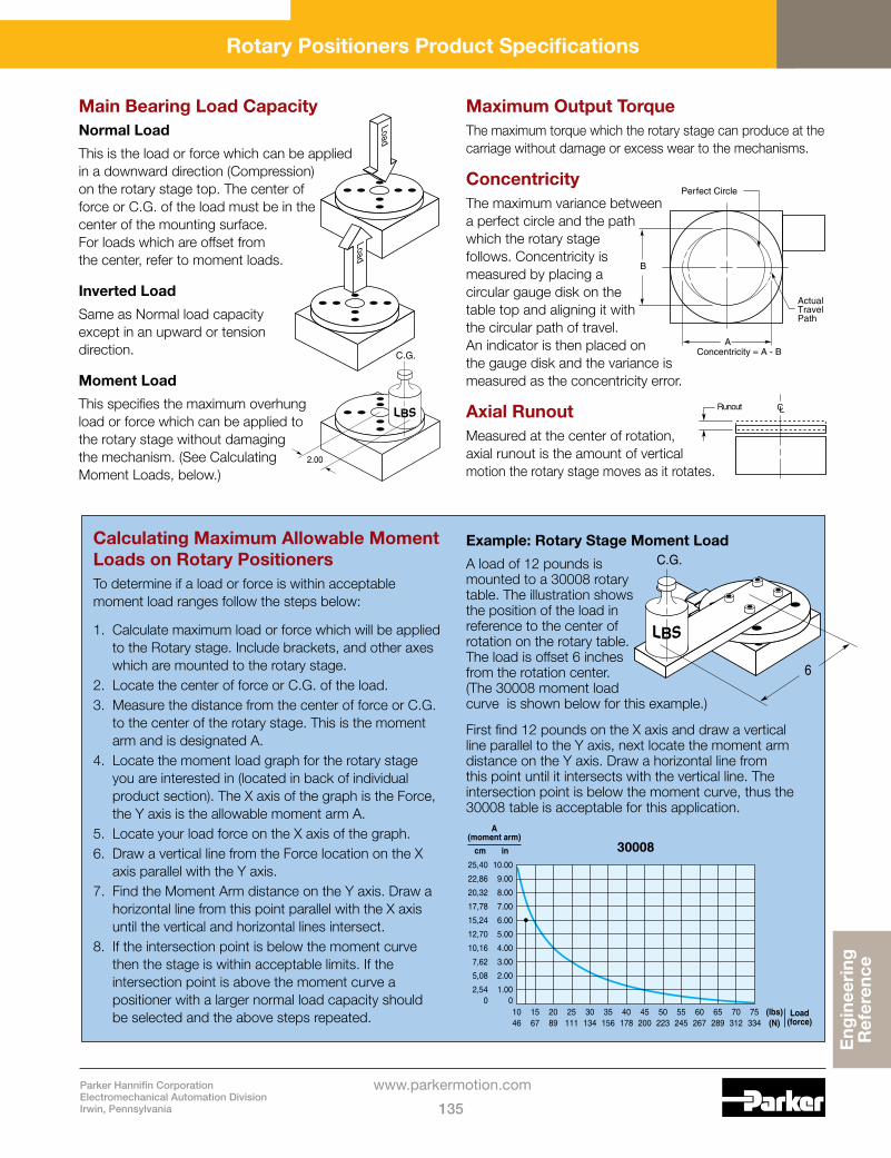
Parker Hannifin CorporationElectromechanical Automation DivisionIrwin, Pennsylvania 135
www.parkermotion.com
Eng
inee
ring
R
efer
ence
Rotary Positioners Product Specifications
Main Bearing Load CapacityNormal Load
This is the load or force which can be applied in a downward direction (Compression) on the rotary stage top. The center of force or C.G. of the load must be in the center of the mounting surface. For loads which are offset from the center, refer to moment loads.
Inverted Load
Same as Normal load capacity except in an upward or tension direction.
Moment Load
This specifies the maximum overhung load or force which can be applied to the rotary stage without damaging the mechanism. (See Calculating Moment Loads, below.)
Load
Load
2.00
C.G.
CLRunout
B
A
Perfect Circle
ActualTravelPath
Concentricity = A - B
Calculating Maximum Allowable Moment Loads on Rotary PositionersTo determine if a load or force is within acceptable moment load ranges follow the steps below:
1. Calculate maximum load or force which will be applied to the Rotary stage. Include brackets, and other axes which are mounted to the rotary stage.
2. Locate the center of force or C.G. of the load.3. Measure the distance from the center of force or C.G.
to the center of the rotary stage. This is the moment arm and is designated A.
4. Locate the moment load graph for the rotary stage you are interested in (located in back of individual product section). The X axis of the graph is the Force, the Y axis is the allowable moment arm A.
5. Locate your load force on the X axis of the graph.6. Draw a vertical line from the Force location on the X
axis parallel with the Y axis.7. Find the Moment Arm distance on the Y axis. Draw a
horizontal line from this point parallel with the X axis until the vertical and horizontal lines intersect.
8. If the intersection point is below the moment curve then the stage is within acceptable limits. If the intersection point is above the moment curve a positioner with a larger normal load capacity should be selected and the above steps repeated.
Example: Rotary Stage Moment Load
A load of 12 pounds is mounted to a 30008 rotary table. The illustration shows the position of the load in reference to the center of rotation on the rotary table. The load is offset 6 inches from the rotation center. (The 30008 moment load curve is shown below for this example.)
First find 12 pounds on the X axis and draw a vertical line parallel to the Y axis, next locate the moment arm distance on the Y axis. Draw a horizontal line from this point until it intersects with the vertical line. The intersection point is below the moment curve, thus the 30008 table is acceptable for this application.
30008in
0
10.00
cm
0
25,40
A(moment arm)
9.0022,86
8.0020,32
7.0017,78
6.0015,24
5.0012,70
4.0010,16
3.007,62
2.005,08
1.002,54
Load(force)
(lbs)(N)
1046
1567
2089
25111
30134
35156
40178
45200
50223
55245
60267
65289
70312
75334
6
C.G.
Maximum Output TorqueThe maximum torque which the rotary stage can produce at the carriage without damage or excess wear to the mechanisms.
ConcentricityThe maximum variance between a perfect circle and the path which the rotary stage follows. Concentricity is measured by placing a circular gauge disk on the table top and aligning it with the circular path of travel. An indicator is then placed on the gauge disk and the variance is measured as the concentricity error.
Axial RunoutMeasured at the center of rotation, axial runout is the amount of vertical motion the rotary stage moves as it rotates.

Model Number Index
Parker Hannifin CorporationElectromechanical Automation Division
Irwin, Pennsylvania136
www.parkermotion.com
105 Contact Factory106
2350 1302355 1302360 1302365 1302370 1312371 1312370 1312371 1312380 1312381 1312450 Contact
Factory2520 1172525 1172530 1172535 1172800
Contact Factory
28052810285029003505-05 163505-10 163505-20 163505-30 163507-05 173507-10 173507-20 173507-30 173510-05 183510-10 183510-20 183511-07 193511-15 193511-20 193511-30 193511-40 193901 203902 663902M 663903 663905 203906 663906M 663907 663909 1243910 124
3922 663922M 663923 663926 663926M 663927 663932 663932M 663933 663936 663936M 663937 663942 663942M 663943 663946 663946M 663947 663952 663952M 663956 663956M 663959 1243960 1243972 663972M 663976 663976M 663982 663982M 663986 663986M 663992 663992M 663996 663996M 664001 214002 684002D 684002M 684003 684004 684004-DM 724004M 684005 214006 684006D 684006M 684007 68
Model Number Page Model Number Page Model Number Page Model Number Page
4008-DM 724009 1244010 1244022 684022D 684022M 684023 684024 684024M 684026 684026D 684026M 684027 684032 684032D 684032M 684033 684034 684034M 684036 684036D 684036M 684037 684042 684042D 684042M 684043 684044 684044M 684046 684046D 684046M 684047 684052 684052D 684052M 684053 684054 684054M 684056 684056D 684056M 684057 684059 1254059A 1254060 1254072 684072D 684072M 68
4073 684074 684074M 684076 684076D 684076M 684077 684082 684082D 684082M 684083 684084 684084M 684086 684086D 684086M 684087 684092 684092D 684092M 684093 684094 684094M 684096 684096D 684096M 684097 684101 224102 704102M 704103 704104 704104-DM 734104M 704201 224202 704202M 704203 704204 704204-DM 734204M 704301 224302 704302M 704303 704304 704304-DM 734304M 704410 26

Parker Hannifin CorporationElectromechanical Automation DivisionIrwin, Pennsylvania 137
www.parkermotion.com
Mo
del
Num
ber
In
dex
Model Number Page Model Number Page Model Number Page Model Number Page
4410-DM 824410-DM-L 824411 804411-L 804412 804412-DM 824412-DM-L 824412-L 804413 804413-L 804414 804414-L 804416 804416-L 804417 804417-L 804418 804418-L 804419 804419-L 804421 804421-L 804422 804422-L 804423 804423-L 804424 804424-L 804426 804426-L 804427 804427-L 804428 804428-L 804429 804429-L 804431 804431-L 804432 804432-L 804433 804433-L 804434 804434-L 804436 804436-L 804437 804437-L 804438 80
4438-L 804439 804439-L 804450 264450-DM 824450-DM-L 824451 804451-L 804452 804452-DM 824452-DM-L 824452-L 804453 804453-L 804454 804454-L 804456 804456-L 804457 804457-L 804458 804458-L 804459 804459-L 804461 804461-L 804462 804462-L 804463 804463-L 804464 804464-L 804466 804466-L 804467 804467-L 804468 804468-L 804469 804469-L 804471 804471-L 804472 804472-L 804473 804473-L 804474 804474-L 804476 80
4476-L 804477 804477-L 804478 804478-L 804479 804479-L 804499 1264501 234502 744502D 744502M 744504-DM 784503 744504 744504M 744506 744506D 744507 744506M 744508-DM 784509 1244510 1254522 744522D 744522M 744523 744524 744524M 744526 744526D 744526M 744527 744532 744532D 744532M 744533 744534 744534M 744536 744536D 744536M 744537 744542 744542D 744542M 744543 744544 744544M 74
4546 744546D 744546M 744547 744552 744552D 744552M 744553 744554 744554M 744556 744556D 744556M 744557 744559 1264560 1264572 744572D 744572M 744573 744574 744574M 744575 1184576 744576D 744576M 744577 744582 744582D 744582M 744583 744584 744584M 744586 744586D 744586M 744587 744592 744592D 744592M 744593 744594 744594M 744596 744596D 744596M 744597 744601 244602 77

Model Number Index
Parker Hannifin CorporationElectromechanical Automation Division
Irwin, Pennsylvania138
www.parkermotion.com
Model Number Page Model Number Page Model Number Page Model Number Page
4602M 774603 774604 774604-DM 794604M 774606 254609 254612 254615 254618 254621 254624 254627 254630 254701 244702 774702M 774703 774704 774704-DM 794704M 774801 244802 774802M 774803 774804 774804-DM 794804M 774900-02 274900-04 284900-06 284900-08 284900-10 284900-12 284910 844910-L 844911 844911-DM 854911-DM-L 854911-L 844912 844912-L 844913 844913-L 844914 844914-L 844915 844915-L 844916 84
4916-L 844917 844917-L 844945-04 864945-04-L 864945-06 864945-06-L 864945-08 864945-08-L 864945-10 864945-10-L 864945-12 864945-12-L 864955-04 864955-04-L 864955-06 864955-06-L 864955-08 864955-08-L 864955-10 864955-10-L 864955-12 864955-12-L 864965-04 864965-04-L 864965-06 864965-06-L 864965-08 864965-08-L 864965-10 864965-10-L 864965-12 864965-12-L 864990-02 1274990-04 1274990-06 1274990-08 1274990-10 1274990-12 1275000 1325100 1325300 1325500
Contact Factory
55055510555056505700 1325800 132
5900 1325950
Contact Factory
9002900690079511E 1289511M 1289512E 1289512M 1289524E 1289524M 1289526E 1289526M 1289531E 1289531M 1289532E 1289532M 1289551 1299552 1299560 1299570 1299575 12910000 11910001 11920000 11920001 11930005-P 12030005-S 12030006-P 12030006-S 12030008-P 12030008-S 12030010-P 12030010-S 12030012-P 12030012-S 120CR4001 40CR4002 92CR4002D 92CR4002M 92CR4002-DM 94CR4022 92CR4022D 92CR4022M 92CR4032 92CR4032D 92CR4032M 92CR4042 92CR4042D 92
CR4042M 92CR4052 92CR4052D 92CR4052M 92CR4072 92CR4072D 92CR4072M 92CR4082 92CR4082D 92CR4082M 92CR4092 92CR4092D 92CR4092M 92CR4101 41CR4102 95CR4102M 95CR4103 95CR4104 95CR4104-DM 96CR4104M 95CR4201 41CR4202 95CR4202M 95CR4203 95CR4204 95CR4204-DM 96CR4204M 95CR4301 41CR4302 95CR4302M 95CR4303 95CR4304 95CR4304-DM 96CR4304M 95CR4410 50CR4411 104CR4411-DM 106CR4411-DM-L 106CR4411-L 104CR4412 104CR4412-DM 106CR4412-DM-L 106CR4412-L 104CR4413 104CR4413-L 104CR4414 104CR4414-L 104CR4416 104CR4416-L 104

Parker Hannifin CorporationElectromechanical Automation DivisionIrwin, Pennsylvania 139
www.parkermotion.com
Mo
del
Num
ber
In
dex
Model Number Page Model Number Page Model Number Page Model Number Page
CR4417 104CR4417-L 104CR4418 104CR4418-L 104CR4419 104CR4419-L 104CR4421 104CR4421-L 104CR4422 104CR4422-L 104CR4423 104CR4423-L 104CR4424 104CR4424-L 104CR4426 104CR4426-L 104CR4427 104CR4427-L 104CR4428 104CR4428-L 104CR4429 104CR4429-L 104CR4431 104CR4431-L 104CR4432 104CR4432-L 104CR4433 104CR4433-L 104CR4434 104CR4434-L 104CR4436 104CR4436-L 104CR4437 104CR4437-L 104CR4438 104CR4438-L 104CR4439 104CR4439-L 104CR4450 50CR4451 104CR4451-DM 106CR4451-DM-L 106CR4451-L 104CR4452 104CR4452-DM 106CR4452-DM-L 106CR4452-L 104CR4453 104CR4453-L 104
CR4454 104CR4454-L 104CR4456 104CR4456-L 104CR4457 104CR4457-L 104CR4458 104CR4458-L 104CR4459 104CR4459-L 104CR4461 104CR4461-L 104CR4462 104CR4462-L 104CR4463 104CR4463-L 104CR4464 104CR4464-L 104CR4466 104CR4466-L 104CR4467 104CR4467-L 104CR4468 104CR4468-L 104CR4469 104CR4469-L 104CR4471 104CR4471-L 104CR4472 104CR4472-L 104CR4473 104CR4473-L 104CR4474 104CR4474-L 104CR4476 104CR4476-L 104CR4477 104CR4477-L 104CR4478 104CR4478-L 104CR4479 104CR4479-L 104CR4501 44CR4502 98CR4502D 98CR4502M 98CR4503 98CR4504 98CR4504-DM 101
CR4504M 98CR4505 44CR4506 98CR4506D 98CR4506M 98CR4507 98CR4522 98CR4522D 98CR4522M 98CR4523 98CR4524 98CR4524M 98CR4526 98CR4526D 98CR4526M 98CR4527 98CR4532 98CR4532D 98CR4532M 98CR4533 98CR4534 98CR4534M 98CR4536 98CR4536D 98CR4536M 98CR4537 98CR4542 98CR4542D 98CR4542M 98CR4543 98CR4544 98CR4544M 98CR4546 98CR4546D 98CR4546M 98CR4547 98CR4552 98CR4552D 98CR4552M 98CR4553 98CR4554 98CR4554M 98CR4556 98CR4556D 98CR4556M 98CR4557 98CR4572 98CR4572D 98CR4572M 98
CR4573 98CR4574 98CR4574M 98CR4576 98CR4576D 98CR4576M 98CR4577 98CR4582 98CR4582D 98CR4582M 98CR4583 98CR4584 98CR4584M 98CR4586 98CR4586D 98CR4586M 98CR4587 98CR4592 98CR4592D 98CR4592M 98CR4593 98CR4594 98CR4594M 98CR4596 98CR4596D 98CR4596M 98CR4597 98CR4601 45CR4602 100CR4602M 100CR4603 100CR4604 100CR4604-DM 101CR4604M 100CR4701 45CR4702 100CR4702M 100CR4703 100CR4704 100CR4704-DM 101CR4704M 100CR4801 45CR4802 100CR4802M 100CR4803 100CR4804 100CR4804-DM 101CR4804M 100CR4900-04 51

Model Number Index
Parker Hannifin CorporationElectromechanical Automation Division
Irwin, Pennsylvania140
www.parkermotion.com
Model Number Page Model Number Page Model Number Page Model Number Page
CR4900-06 51CR4900-08 51CR4900-10 51CR4900-12 51CR4910 108CR4910-L 108CR4911 108CR4911-DM 109CR4911-DM-L 109CR4911-L 108CR4912 108CR4912-L 108CR4913 108CR4913-L 108CR4914 108CR4914-L 108CR4915 108CR4915-L 108CR4916 108CR4916-L 108CR4917 108CR4917-L 108CR4945-04 110CR4945-04-L 110CR4945-06 110CR4945-06-L 110CR4945-08 110CR4945-08-L 110CR4945-10 110CR4945-10-L 110CR4945-12 110CR4945-12-L 110CR4955-04 110CR4955-04-L 110CR4955-06 110CR4955-06-L 110CR4955-08 110CR4955-08-L 110CR4955-10 110CR4955-10-L 110CR4955-12 110CR4955-12-L 110CR4965-04 110CR4965-04-L 110CR4965-06 110CR4965-06-L 110CR4965-08 110CR4965-08-L 110CR4965-10 110
CR4965-10-L 110CR4965-12 110CR4965-12-L 110M2520 117M2525 117M2530 117M2535 117M3901 20M3902 66M3902M 66M3903 66M3905 20M3906 66M3906M 66M3907 66M3909 124M3910 124M3922 66M3922M 66M3923 66M3926 66M3926M 66M3927 66M3932 66M3932M 66M3933 66M3936 66M3936M 66M3937 66M3942 66M3942M 66M3943 66M3946 66M3946M 66M3947 66M3952 66M3952M 66M3956 66M3956M 66M3959 124M3960 124M3972 66M3972M 66M3976 66M3976M 66M3982 66M3982M 66M3986 66M3986M 66
M3992 66M3992M 66M3996 66M3996M 66M4001 21M4002 68M4002D 68M4002M 68M4003 68M4004 68M4004-DM 72M4004M 68M4005 21M4006 68M4006D 68M4006M 68M4007 68M4008-DM 72M4009 124M4010 124M4022 68M4022D 68M4022M 68M4023 68M4024 68M4024M 68M4026 68M4026D 68M4026M 68M4027 68M4032 68M4032D 68M4032M 68M4033 68M4034 68M4034M 68M4036 68M4036D 68M4036M 68M4037 68M4042 68M4042D 68M4042M 68M4043 68M4044 68M4044M 68M4046 68M4046D 68M4046M 68
M4047 68M4052 68M4052D 68M4052M 68M4053 68M4054 68M4054M 68M4056 68M4056D 68M4056M 68M4057 68M4059 125M4059A 125M4060 125M4072 68M4072D 68M4072M 68M4073 68M4074 68M4074M 68M4076 68M4076D 68M4076M 68M4077 68M4082 68M4082D 68M4082M 68M4083 68M4084 68M4084M 68M4086 68M4086D 68M4086M 68M4087 68M4092 68M4092D 68M4092M 68M4093 68M4094 68M4094M 68M4096 68M4096D 68M4096M 68M4097 68M4101 22M4102 70M4102M 70M4103 70M4104 70

Parker Hannifin CorporationElectromechanical Automation DivisionIrwin, Pennsylvania 141
www.parkermotion.com
Mo
del
Num
ber
In
dex
Model Number Page Model Number Page Model Number Page Model Number Page
M4104-DM 73M4104M 70M4201 22M4202 70M4202M 70M4203 70M4204 70M4204-DM 73M4204M 70M4301 22M4302 70M4302M 70M4303 70M4304 70M4304-DM 73M4304M 70M4410 26M4410-DM 82M4410-DM-L 82M4411 80M4411-L 80M4412 80M4412-DM 82M4412-DM-L 82M4412-L 80M4413 80M4413-L 80M4414 80M4414-L 80M4416 80M4416-L 80M4417 80M4417-L 80M4418 80M4418-L 80M4419 80M4419-L 80M4421 80M4421-L 80M4422 80M4422-L 80M4423 80M4423-L 80M4424 80M4424-L 80M4426 80M4426-L 80M4427 80M4427-L 80
M4428 80M4428-L 80M4429 80M4429-L 80M4431 80M4431-L 80M4432 80M4432-L 80M4433 80M4433-L 80M4434 80M4434-L 80M4436 80M4436-L 80M4437 80M4437-L 80M4438 80M4438-L 80M4439 80M4439-L 80M4450 26M4450-DM 82M4450-DM-L 82M4451 80M4451-L 80M4452 80M4452-DM 82M4452-DM-L 82M4452-L 80M4453 80M4453-L 80M4454 80M4454-L 80M4456 80M4456-L 80M4457 80M4457-L 80M4458 80M4458-L 80M4459 80M4459-L 80M4461 80M4461-L 80M4462 80M4462-L 80M4463 80M4463-L 80M4464 80M4464-L 80
M4466 80M4466-L 80M4467 80M4467-L 80M4468 80M4468-L 80M4469 80M4469-L 80M4471 80M4471-L 80M4472 80M4472-L 80M4473 80M4473-L 80M4474 80M4474-L 80M4476 80M4476-L 80M4477 80M4477-L 80M4478 80M4478-L 80M4479 80M4479-L 80M4499 126M4501 23M4502 74M4502D 74M4502M 74M4503 74M4504 74M4504-DM 78M4504M 74M4505 23M4506 74M4506D 74M4506M 74M4507 74M4508-DM 78M4509 124M4510 125M4522 74M4522D 74M4522M 74M4523 74M4524 74M4524M 74M4526 74M4526D 74
M4526M 74M4527 74M4532 74M4532D 74M4532M 74M4533 74M4534 74M4534M 74M4536 74M4536D 74M4536M 74M4537 74M4542 74M4542D 74M4542M 74M4543 74M4544 74M4544M 74M4546 74M4546D 74M4546M 74M4547 74M4552 74M4552D 74M4552M 74M4553 74M4554 74M4554M 74M4556 74M4556D 74M4556M 74M4557 74M4559 126M4560 126M4572 74M4572D 74M4572M 74M4573 74M4574 74M4574M 74M4575 118M4576 74M4576D 74M4576M 74M4577 74M4582 74M4582D 74M4582M 74M4583 74

Model Number Index
Parker Hannifin CorporationElectromechanical Automation Division
Irwin, Pennsylvania142
www.parkermotion.com
Model Number Page Model Number Page Model Number Page Model Number Page
M4584 74M4584M 74M4586 74M4586D 74M4586M 74M4587 74M4592 74M4592D 74M4592M 74M4593 74M4594 74M4594M 74M4596 74M4596D 74M4596M 74M4597 74M4601 24M4602 77M4602M 77M4603 77M4604 77M4604-DM 79M4604M 77M4701 24M4702 77M4702M 77M4703 77M4704 77M4704-DM 79M4704M 77M4801 24M4802 77M4802M 77M4803 77M4804 77M4804-DM 79M4804M 77M4900-02 27M4900-04 28M4900-06 28M4900-08 28M4900-10 28M4900-12 28M4910 84M4910-L 84M4911 84M4911-DM 85M4911-DM-L 85M4911-L 84
M4912 84M4912-L 84M4913 84M4913-L 84M4914 84M4914-L 84M4915 84M4915-L 84M4916 84M4916-L 84M4917 84M4917-L 84M4945-04 86M4945-04-L 86M4945-06 86M4945-06-L 86M4945-08 86M4945-08-L 86M4945-10 86M4945-10-L 86M4945-12 86M4945-12-L 86M4955-04 86M4955-04-L 86M4955-06 86M4955-06-L 86M4955-08 86M4955-08-L 86M4955-10 86M4955-10-L 86M4955-12 86M4955-12-L 86M4965-04 86M4965-04-L 86M4965-06 86M4965-06-L 86M4965-08 86M4965-08-L 86M4965-10 86M4965-10-L 86M4965-12 86M4965-12-L 86M4990-02 127M4990-04 127M4990-06 127M4990-08 127M4990-10 127M4990-12 127M10000 119
M10001 119M20000 119M20001 119M30005-P 120M30005-S 120M30006-P 120M30006-S 120M30008-P 120M30008-S 120M30010-P 120M30010-S 120M30012-P 120M30012-S 120MM-1 X 64MM-1 X-Y 64MM-1 X-Y-Z 64MM-3 X 64MM-3 X-Y 64MM-3 X-Y-Z 64SC050A-075 97SC050A-125 97SC050A-175 97SC075A-100 102SC075A-150 102SC075A-200 102SC100A-150 103SC100A-200 103SC100A-250 103SC100A-300 103SE050A-050 42SE050A-075 42SE050A-100 42SE050A-125 42SE050A-150 42SE050A-175 42SE050A-225 42SE075A-075 46SE075A-100 46SE075A-125 46SE075A-150 46SE075A-175 46SE075A-225 46SE100A-100 48SE100A-150 48SE100A-250 48SE100A-350 48
SK050A-075 97SK050A-125 97SK050A-175 97SK075A-100 102SK075A-150 102SK075A-200 102SK100A-150 103SK100A-200 103SK100A-250 103SK100A-300 103SP050A-075 43SP050A-125 43SP050A-175 43SP075A-150 47SP075A-200 47SP100A-150 49SP100A-200 49SP100A-250 49SP100A-300 49SW038A-050 39SW038A-075 39SW038A-100 39SW038A-125 39SW038A-150 39SW038A-175 39SW038A-225 39

Parker Hannifin CorporationElectromechanical Automation DivisionIrwin, Pennsylvania 143
www.parkermotion.com
Off
er o
f S
ale
1. Terms and Conditions of Sale: All descriptions, quotations, proposals, offers acknowledgments, acceptances and sales of Seller’s products are subject to and shall be governed exclusively by the terms and conditions stated herein. Buyer’s acceptance of any offer to sell is limited to these terms and conditions. Any terms or conditions in addition to, or inconsistent with those stated herein, proposed by Buyer in any acceptance of an offer by Seller, are hereby objected to. No such additional, different or inconsistent terms and conditions shall become part of the contract between, Buyer and Seller unless expressly accepted in writing by Seller. Seller’s acceptance of any offer to purchase by Buyer is expressly conditional upon Buyer’s assent to all the terms and conditions stated herein, including any terms in addition to, or inconsistent with those contained in Buyer’s offer. Acceptance of Seller’s products shall in all events constitute such assent.
2. Payment: Payment shall be made by Buyer net 30 days from the date of delivery of the items purchased hereunder. Amounts not timely paid shall bear interest at the maximum rate permitted by law for each month or portion thereof that the Buyer is late in making payment. Any claims by Buyer for omissions or shortages in a shipment shall be waived unless Seller receives notice thereof within 30 days after Buyer’s receipt of the shipment.
3. Delivery: Unless otherwise provided on the face hereof, delivery shall be made F.O.B. Seller’s plant. Regardless of the method of delivery, however, risk of loss shall pass to Buyer upon Seller’s delivery to a carrier. Any delivery dates shown are approximate only and Seller shall have no liability for any delays in delivery.
4. Warranty: Seller warrants that the items sold hereunder shall be free from defects in material or workmanship for a period of 12 months from date of shipment from Parker Daedal. THIS WARRANTY COMPRISES THE SOLE AND ENTIRE WARRANTY PERTAINING TO ITEMS PROVIDED HEREUNDER. SELLER MAKES NO OTHER WARRANTY, GUARANTEE, OR REPRESENTATION OF ANY KIND WHATSOEVER. ALL OTHER WAR-RANTIES, INCLUDING BUT NOT LIMITED TO, MERCHANTABILITY AND FITNESS FOR PURPOSE, WHETHER EXPRESS, IMPLIED, OR ARISING BY OPERATION OF LAW, TRADE USAGE, OR COURSE OF DEALING ARE HEREBY DISCLAIMED. NOTWITHSTANDING THE FOREGOING, THERE ARE NO WARRANTIES WHATSOEVER ON ITEMS BUILT OR ACQUIRED WHOLLY OR PARTIALLY, TO BUYER’S DESIGNS OR SPECIFICATIONS.
5. Limitation of Remedy: SELLER’S LIABILITY ARISING FROM OR IN ANY WAY CONNECTED WITH THE ITEMS SOLD OR THIS CONTRACT SHALL BE LIMITED EXCLUSIVELY TO REPAIR OR REPLACEMENT OF THE ITEMS SOLD OR REFUND OF THE PURCHASE PRICE PAID BY BUYER, AT SELLER’S SOLE OPTION. IN NO EVENT SHALL SELLER BE LIABLE FOR ANY INCIDENTAL, CONSEQUENTIAL OR SPECIAL DAMAGES OF ANY KIND OR NATURE WHATSOEVER, INCLUDING BUT NOT LIMITED TO LOST PROFITS ARISING FROM OR IN ANY WAY CONNECTED WITH THIS AGREEMENT OR ITEMS SOLD HEREUNDER, WHETHER ALLEGED TO ARISE FORM BREACH OF CONTRACT, EXPRESS OR IMPLIED WARRANTY, OR IN TORT, INCLUDING WITHOUT LIMITATION, NEGLIGENCE, FAILURE TO WARN OR STRICT LIABILITY.
6. Changes, Reschedules and Cancellations: Buyers may request to modify the designs or specifications for the items sold hereunder as well as the quantities and delivery dates thereof, or may request to cancel all or part of this order, however, no such requested modification or cancellation shall become part of the contract between Buyer and Seller unless accepted by Seller in a written amendment to this Agreement. Acceptance of any such requested modification of cancellation shall be at Seller’s discretion, and shall be upon such terms and conditions as Seller may require.
7. Special Tooling: A tooling charge may be imposed for any special tooling, including without limitation, dies, fixtures, molds and patterns, acquired to manufacture items sold pursuant to this contract. Such special tooling shall be and remain Seller’s property notwithstanding payment of any charges by Buyer. In no event will Buyer acquire any interest in apparatus belonging to Seller which is utilized in the manufacture of the items sold hereunder, even if such apparatus has been specially converted or adapted for such manufacture and not withstanding any charges paid by Buyer. Unless otherwise agreed, Seller shall have the right to alter, discard or otherwise dispose of any special tooling or other property in its sole discretion at any time.
8. Buyer’s Property: Any designs, tools, patterns, materials, drawings confidential information or equipment furnished by Buyer, or any other items which become Buyer’s property, may be considered obsolete and may be destroyed by Seller after two (2) consecutive years have elapsed without Buyer placing an order for the items which are manufactured using such property. Seller shall not be responsible for any loss or damage to such property while it is in Seller’s possession or control.
9. Taxes: Unless otherwise indicated on the face hereof, all prices and charges are exclusive of excise, sales, use, property, occupational or like taxes which may be imposed by any taxing authority upon the manufacture, sale or delivery of the items sold hereunder. If any such taxes must be paid by Seller or if Seller is liable for the collection of such tax, the amount thereof shall be in addition to the amounts for the items sold. Buyer agrees to pay all such taxes or to reimburse Seller therefore upon receipt of its invoice. If Buyer claims exemption from any sales, use or other tax imposed by any taxing authority, Buyer shall save Seller harmless from and against any such tax, together with any interest or penalties thereon which may be assessed if the items are held to be taxable.
10. Indemnity For Infringement of Intellectual Property Rights: Seller shall have no liability for infringement of any patents, trademarks, copyrights, trade dress, trade secrets or similar rights except as provided in this Part 10. Seller will defend and indemnify Buyer against allegations of infringement of U.S. patents, U.S. trademarks, copyrights, trade dress and trade secrets (hereinafter ‘Intellectual Property Rights’). Seller will defend at its expense and will pay the cost of any settlement or damages awarded in an action brought against Buyer based on an allegation that an item sold pursuant to this contract infringes the Intellectual Property Rights of a third party. Seller’s obligation to defend and indemnify Buyer is contingent on Buyer notifying Seller within ten (10) days after Buyer becomes aware of such allegations of infringement, and Seller having sole control over the defense of any allegations or actions including all negotiations for settlement or compromise. If an item sold hereunder is subject to a claim that it infringes the Intellectual Property Rights of a third party, Seller may, at its sole expense and option, procure for Buyer the right to continue using said item, replace or modify said item so as to make it non infringing, or offer to accept return of said item and return the purchase price less a reasonable allowance for depreciation. Notwithstanding the foregoing, Seller shall have no liability for claims of infringement based on information provided by Buyer, or directed to items delivered hereunder for which the designs are specified in whole or part by Buyer, or infringements resulting from the modification, combination or use in a system of any item sold hereunder. The foregoing provisions of this Part 10 shall constitute Seller’s sole and exclusive liability and Buyer’s sole and exclusive remedy for infringement of Intellectual Property Right. If a claim is based on information provided by Buyer or if the design for an item delivered hereunder is specified in whole or in part by Buyer, Buyer shall defend and indemnify Seller for all costs, expenses or judgments resulting from any claim that such item infringes any patent, trademark, copyright, trade dress, trade secret or any similar right.
11. Force Majeure: Seller does not assume the risk of and shall not be liable for delay or failure to perform any of Seller’s obligations by reason of circumstances beyond the reasonable control of Seller (hereinafter ‘Events of Force Majeure’). Events of Force Majeure shall include without limitation, accidents, acts of God, strikes or labor disputes, acts, laws, rules or regulations of any government or government agency, fires, floods, delays or failures in delivery of carriers or suppliers, shortages of materials and any other cause beyond Seller’s control.
12. Entire Agreement/Governing Law: The terms and conditions set forth herein, together with any amendments, modifications and any different terms or conditions expressly accepted by Seller in writing, shall constitute the entire Agreement concerning the items sold, and there are no oral or other representations or agreements which pertain thereto. This Agreement shall be governed in all respects by the law of the State of Ohio. No actions arising out of the sale of the items sold hereunder of this Agreement may be brought by either party more than two (2) years after the cause of action accrues.
The items described in this document and other documents or descriptions provided by Parker Daedal, its subsidiaries and its authorized distributors are hereby offered for sale at prices to be established by Parker Daedal, its subsidiaries and its authorized distributors. This offer and its acceptance by any customer (“Buyer”) shall be governed by all of the following Terms and Conditions. Buyer’s order for any such item, when communicated to Parker Daedal, its subsidiary or an authorized distributor (“Seller”) verbally or in writing, shall constitute acceptance of this offer.
Offer of Sale

Offer of Sale
Parker Hannifin CorporationElectromechanical Automation Division
Irwin, Pennsylvania144
www.parkermotion.com
FAILURE OR IMPROPER SELECTION OR IMPROPER USE OF THE PRODUCTS AND/OR SYSTEMS DESCRIBED HEREIN OR RELATED ITEMS CAN CAUSE DEATH,
PERSONAL INJURY AND PROPERTY DAMAGE.
This document and other information from Parker Hannifin Corporation, its subsidiaries and authorized distributors provide product and/or system options for further investigation by users having technical expertise. It is important that you analyze all aspects of your application and review the information concerning the product or system in the current product catalog. Due to the variety of operating conditions and applications for these products or systems, the user, through its own analysis and testing, is solely responsible for making the final selection of the products and systems and assuring that all performance, safety and warning requirements of the application are met.
The products described herein, including without limitation, product features, specifications, designs, availability and pricing, are subject to change by Parker Hannifin Corporation and its subsidiaries at any time without notice.
WARNING
The items described in this document are hereby offered for sale by Parker Hannifin Corporation, its subsidiaries or its authorized distributors. This offer and its acceptance are governed by the provisions stated in the “Offer of Sale” found on the last page of this publication.
© Copyright 2009, Parker Hannifin Corporation, All Rights Reserved
Offer of Sale

Rotary Actuators
Industry leader in the design and manufacture of pneu-matic rack and pinion, and vane-style rotary actuators.www.parker.com/pneu/rotary
Vacuum Products and Sensors
Vacuum solutions include a broad range of genera-tors (integrated/inline), cups, and pressure sensors.www.parker.com/pneu/vacsen
Airline Accessories
Airline accessories include silencers, flow controls, and mufflers to round out Parker’s pneumatic solution.www.parker.com/pneu/access
Parallel, angular, and three jaw grippers are available in over 1,000 configura-tions.www.parker.com/pneu/gripper
Motors and Drives
Parker’s family of innova-tive servo/stepper motors and drives continues to expand to meet the chal-lenges of new technologies.www.parkermotion.com/em/motordrive
Linear Actuators
Aluminum and steel pneumatic cylinders, guided cylinders, rodless cylinders, and short stroke thrusters from the industry leader.www.parkermotion.com/pneu/linear
Electric Actuators
Screw, belt-driven, and linear motor actuators for the complete range of industrial applications, offering precise motion and flexibility.
www.parkermotion.com/em/linear
Superior integration and support for machine control as well as HMI hardware and software.
www.parkermotion.com/em/hmicont
HMI and Controllers
Grippers
Extensive Automation Solutions
Parker IPS Structural Automation
More than 150 metric and inch profiles, integral motion components, and accessories for unlimited and flexible configurations. Pre-machined kits or complete assemblies.
www.parker.com/ips
Air Preparation
Parker, the industry leader in air preparation, offers a complete line of products to ensure clean, dry, oil-free air.www.parker.com/pneu/airprep
The most complete line of fluid connectors worldwide will meet virtually any automation application.
www.parker.com/pneu/fc
Connectors and Tubing
Valve technology that meets the most demanding requirements in any industrial application.
www.parker.com/pneu/valve
Air Control Valves
New Parker Daedal catalog. Call for your comprehensive guide today. 800-245-6903 Catalog 8092
Parker also has product ranges available for the
Precision Automation, Industrial Automation
and Pneumatic markets, each paired with an
interactive CD. Call 800-CPARKER.
Bulletin AU01-7500/US
Bulletin AU01-1000/US
Bulletin AU01-5000/US
Daedal Electromechanical Positioning Systems

Parker Hannifin CorporationElectromechanical Automation Div. 1140 Sandy Hill Road Irwin, PA 15642 Tel: 800-245-6903 Email: [email protected] [email protected]
Catalog 8099-M 6/09Printed in U.S.A
AustraliaParker Hannifin (Australia) Pty Limited9 Carrington RoadCastle Hill NSW 2154AustraliaTel: +61 (0) 2 9634-7777 Fax: +61 (0) 2 9634 3749
BrazilParker Hannifin Ind. Com Ltda.Av. Lucas Nogueira Garcez 2181Esperança12325-900 Jacareí, SPTel: 12 3954 5100Fax: 12 3954 5262Email: [email protected] CanadaParker Hannifin (Canada) Inc.160 Chisholm Dr Milton, Ontario L9T 3G9 Tel: 905-693-3000 Fax: 905-876-1958 Email: [email protected]
ChinaParker Hannifin Motion & Control (Shanghai) Co., Ltd280 Yunqiao Rd. Jin Qiao Export Processing ZoneShanghai 201206, ChinaTel: (86-21) 50312525Fax: (86-21) 64459717
FranceParker SSD Parvex8 avenue du LacB.P. 249F-21007 Dijon CedexTel: +33 (0) 3 80 42 41 40Fax: +33 (0) 3 80 42 41 23
GermanyElectromechanical EuropeParker Hannifin GmbH & Co KGRobert-Bosch-Strasse 22 D-77656 OffenburgGermanyTel: +49 (0) 781 509 0Fax: +49 (0) 781 509 98176
IndiaParker Hannifin India Pvt. Ltd Automation Group-SSD Drives Division133 & 151 Developed Plots EstatePerungudi, Chennai 600 096Tel: 044-4391-0799Fax: 044-4391-0700
ItalyParker Hannifin SpA Via Gounod 120092 Cinsello BalsamoMilano, ItalyTel: +39 02 361081Fax: +39 02 36108400
KoreaParker Hannifin Korea9th Floor KAMCO Yangjae Tower949-3 Dogok 1-dong Gangnam-guSeoul 135-860, KoreaTel: 82-2-559-0454Fax: 82-2-556-8187
MexicoParker Hannifin de MexicoEje uno Norte No.100 Parque Industrial Toluca 2000 Toluca, CP 50100 MéxicoTel: 52-722-275-4200Fax: 52-722-279-0316
SingaporeParker Hannifin Singapore Pte Ltd11, Fourth Chin Bee RoadSingapore 619702Tel: (65) 6887 6300Fax: (65) 6265 5125/6261 4929
TaiwanParker Hannifin Taiwan Co., LtdNo. 40, Wuchiuan 3rd RoadWuku Industrial ParkTaipei County, Taiwan 248ROCTel: 886 2 2298 8987Fax: 886 2 2298 8982
ThailandParker Hannifin (Thailand) Co., Ltd.1023, 3rd Floor, TPS Building, Pattanakarn Road, Suanluang, Bangkok 10250 Thailand Tel: (66) 02717 8140Fax: (66) 02717 8148
UK Parker Hannifin Ltd.Tachbrook Park DriveTachbrook ParkWarwick CV34 6TUTel: +44 (0) 1926 317970Fax: +44 (0) 1926 317980
USAParker Hannifin Electromechanical Automation Division Main Office/Compumotor/CTC5500 Business Park DriveRohnert Park, CA 94928 USATel: 707-584-7558 800-358-9070Fax: 707-584-8015Email: [email protected]
Parker Hannifin Electromechanical Automation Division/Bayside27 Seaview BoulevardPort Washington, NY 11050Tel: 707-584-7558 800-358-9070Fax: 707-584-8015Email: [email protected]
Parker Hannifin Electromechanical Automation Division/Daedal1140 Sandy Hill RoadIrwin, PA 15642Tel: 724-861-8200 800-245-6903Fax: 724-861-3330 Email: [email protected]
EM Sales Offices
This catalog is printed on 100% recycled paper;
30% post-consumer content.