blast load analysis of a concre te column … order to do the blast analysis in autodyn, ......
TRANSCRIPT

http://www.iaeme.com/IJCIET/index.
International Journal of Civil Engineering and Technology (IJCIET)Volume 8, Issue 4, April 2017, pp.
Available online at http://www.iaeme.com/IJCIET/issues.
ISSN Print: 0976-6308 and ISSN Online: 0976
© IAEME Publication
BLAST LOAD
COLUMN EMBEDDED WITH
M.Tech Student,
Mar Athanasius College of Engineering, Kothamangalam, Kerala, India
Associate Professor, Department of Civil Engineering
Toc-H College of Engineering, Ernakulam, Kerala, India
ABSTRACT
This study investigates the behaviour of a concrete column embedded with
pretwisted bars subjected to blast loading. Pretwisted bars are those that are twisted
along its central axis. It has been found out that the buckling capacity of the steel bars
increases as the angle of twist increases. As a preliminary step, we find the optimum
angle of twist for the steel bar by the buckling analysis of the bar over a set of twist
angles. The steel bar twisted at this optimum angle is embedded in the concrete
column. The column is of size 250 mm
ANSYS Workbench 16.0. Later on, it was subjected to Blast Loading. The Blast
analysis of the concrete column was done in ANSYS AUTODYN. The explosive was
placed at a stand-off distance of 1500 mm. The blast analysis was carried out for
5000 kg, 3000 kg, 300 kg and 10 kg of TNT
air box around the column to act as a medium for the blast. In order to reduce the
large time consumption of the blast analysis, a one dimensional wedge which is filled
with AIR and TNT materials was created in AUTODYN and it was remapped into the
3 D Air box. The blast analysis of the column is continued till the column failure or
the kinetic energy absorbed in the column diminishes. The results from blast analysis
shows that the column failed when subjected to
can withstand with minute damages when subjected to 300 kg and 10 kg. The current
study includes only blast analysis of columns that are unloaded.
Key word: Pretwisted bars, Buckling Analysis, Blast Analysis, TNT, AUTODYN, Re
mapping.
Cite this Article: AnuSneha John and Dr. Nivin Philip, Blast Load Analysis of a
Concrete Column with Pretwisted bars
and Technology ,8(4), 201
http://www.iaeme.com/IJCI
IJCIET/index.asp 1768 [email protected]
International Journal of Civil Engineering and Technology (IJCIET) 2017, pp. 1768–1777 Article ID: IJCIET_08_04_200
http://www.iaeme.com/IJCIET/issues.asp?JType=IJCIET&VType=8&IType=4
6308 and ISSN Online: 0976-6316
Scopus Indexed
LOAD ANALYSIS OF A CONCRE
COLUMN EMBEDDED WITH PRETWISTED
BARS
AnuSneha John
M.Tech Student, Computer Aided Structural Engineering
Mar Athanasius College of Engineering, Kothamangalam, Kerala, India
Dr. Nivin Philip
Associate Professor, Department of Civil Engineering
H College of Engineering, Ernakulam, Kerala, India
This study investigates the behaviour of a concrete column embedded with
pretwisted bars subjected to blast loading. Pretwisted bars are those that are twisted
along its central axis. It has been found out that the buckling capacity of the steel bars
ases as the angle of twist increases. As a preliminary step, we find the optimum
angle of twist for the steel bar by the buckling analysis of the bar over a set of twist
bar twisted at this optimum angle is embedded in the concrete
. The column is of size 250 mm×250 mm. The software used for mode
ANSYS Workbench 16.0. Later on, it was subjected to Blast Loading. The Blast
analysis of the concrete column was done in ANSYS AUTODYN. The explosive was
off distance of 1500 mm. The blast analysis was carried out for
, 3000 kg, 300 kg and 10 kg of TNT. For the blast analysis, we created a 3 D
air box around the column to act as a medium for the blast. In order to reduce the
consumption of the blast analysis, a one dimensional wedge which is filled
with AIR and TNT materials was created in AUTODYN and it was remapped into the
3 D Air box. The blast analysis of the column is continued till the column failure or
rgy absorbed in the column diminishes. The results from blast analysis
shows that the column failed when subjected to 5000 kg, 3000 kg TNT blast whereas it
can withstand with minute damages when subjected to 300 kg and 10 kg. The current
y blast analysis of columns that are unloaded.
Pretwisted bars, Buckling Analysis, Blast Analysis, TNT, AUTODYN, Re
AnuSneha John and Dr. Nivin Philip, Blast Load Analysis of a
Concrete Column with Pretwisted bars. International Journal of Civil Engineering
), 2017, pp. 1768-1777
CIET/issues.asp?JTypeIJCIET&VType=6&IType=
asp?JType=IJCIET&VType=8&IType=4
ANALYSIS OF A CONCRETE
PRETWISTED
Computer Aided Structural Engineering
Mar Athanasius College of Engineering, Kothamangalam, Kerala, India
H College of Engineering, Ernakulam, Kerala, India
This study investigates the behaviour of a concrete column embedded with
pretwisted bars subjected to blast loading. Pretwisted bars are those that are twisted
along its central axis. It has been found out that the buckling capacity of the steel bars
ases as the angle of twist increases. As a preliminary step, we find the optimum
angle of twist for the steel bar by the buckling analysis of the bar over a set of twist
bar twisted at this optimum angle is embedded in the concrete
mm. The software used for modeling was
ANSYS Workbench 16.0. Later on, it was subjected to Blast Loading. The Blast
analysis of the concrete column was done in ANSYS AUTODYN. The explosive was
off distance of 1500 mm. The blast analysis was carried out for
. For the blast analysis, we created a 3 D
air box around the column to act as a medium for the blast. In order to reduce the
consumption of the blast analysis, a one dimensional wedge which is filled
with AIR and TNT materials was created in AUTODYN and it was remapped into the
3 D Air box. The blast analysis of the column is continued till the column failure or
rgy absorbed in the column diminishes. The results from blast analysis
5000 kg, 3000 kg TNT blast whereas it
can withstand with minute damages when subjected to 300 kg and 10 kg. The current
Pretwisted bars, Buckling Analysis, Blast Analysis, TNT, AUTODYN, Re-
AnuSneha John and Dr. Nivin Philip, Blast Load Analysis of a
International Journal of Civil Engineering
&IType=7
Blast Load Analysis of A Concrete Column Embedded with Pretwisted Bars
http://www.iaeme.com/IJCIET/index.asp 1769 [email protected]
1. INTRODUCTION
Pretwisted bars are the steel bars that are twisted along its central axis. Many researchers have
found out that the buckling capacity of a steel bar increases with the increase of twist angle.
The concept is, an axially loaded compression member buckles about the section with least
resistance and for a pretwisted bar the direction of the least resistance varies along its central
axis. The coupling of the strong and weaker planes results in higher buckling capacity. On the
basis of this fact, we modeled a concrete column embedded with pretwisted bars and it was
subjected to blast loading. The blast loading is done for different explosive capacities. The
explosive capacities differ on the basis of the weight of TNT used.
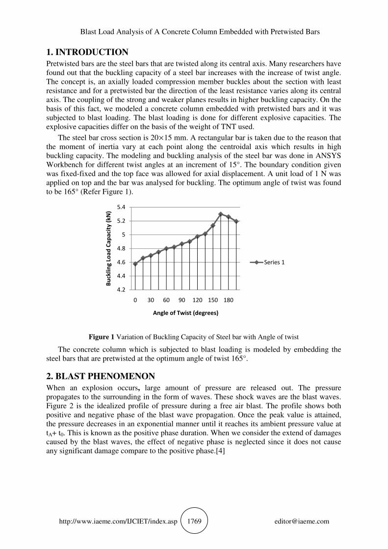
The steel bar cross section is 20×15 mm. A rectangular bar is taken due to the reason that
the moment of inertia vary at each point along the centroidal axis which results in high
buckling capacity. The modeling and buckling analysis of the steel bar was done in ANSYS
Workbench for different twist angles at an increment of 15°. The boundary condition given
was fixed-fixed and the top face was allowed for axial displacement. A unit load of 1 N was
applied on top and the bar was analysed for buckling. The optimum angle of twist was found
to be 165° (Refer Figure 1).
Figure 1 Variation of Buckling Capacity of Steel bar with Angle of twist
The concrete column which is subjected to blast loading is modeled by embedding the
steel bars that are pretwisted at the optimum angle of twist 165°.
2. BLAST PHENOMENON
When an explosion occurs, large amount of pressure are released out. The pressure
propagates to the surrounding in the form of waves. These shock waves are the blast waves.
Figure 2 is the idealized profile of pressure during a free air blast. The profile shows both
positive and negative phase of the blast wave propagation. Once the peak value is attained,
the pressure decreases in an exponential manner until it reaches its ambient pressure value at
tA+ t0. This is known as the positive phase duration. When we consider the extend of damages
caused by the blast waves, the effect of negative phase is neglected since it does not cause
any significant damage compare to the positive phase.[4]
4.2
4.4
4.6
4.8
5
5.2
5.4
0 30 60 90 120 150 180
Bu
ckli
ng
Lo
ad
Ca
pa
city
(k
N)
Angle of Twist (degrees)
Series 1

AnuSneha John and Dr. Nivin Philip
http://www.iaeme.com/IJCIET/index.asp 1770 [email protected]
Figure 2 Idealized Pressure Wave Profile [4]
3. METHODOLOGY
The concrete column is modeled in ANSYS Workbench 16.0. In order to do the blast analysis
in AUTODYN, the column has to be modelled in Explicit Dynamics. The materials of the
model should be explicit materials, otherwise AUTODYN solver cannot analyse the model.
3.1 Material Modelling
The material models for the Explicit dynamics materials are different. The concrete material
from explicit dynamics is M35 CONCRETE and its material model is a Riedel-Heirmaier-
Thoma (RHT) model. For the steel 4340, the material model is Johnson Cook (J-C) model.
Therefore, we have inputted the parameters of each model for the corresponding material.
The RHT (Riedel-Hiermaier-Thoma) model is very helpful in modelling concrete for
dynamic loading. It is a combination of both plasticity and shear damage model. The equation
for the RHT model is given in Equation 1. [4]
3( ( . ) ) ( ) ( ) (1)NHTL
fail c rate rate
c c
ppY f A F R F
f fθ ε= −
Where c
f is the compressive strength,HTL
p is the tensile strength, p is the hydrostatic pressure,
rateF is the strain rate factor, 3( )R θ is the internal resistance force and A , N are the constants
Johnson Cook (J-C) model is used for the material modelling of the steel reinforcement.
The coefficients of the J-C model improves the predictability of the response of the material
and also the strain rate effect on the stress flow grew higher. The mathematical expression for
the stress flow is given by the Equation 2. [4]
( )[ ( ) ][1 ln ][1 { } ] 2p n p mroom
flow
melt room
T TA B C
T Tσ ε ε
−= + + −
−
Where flowσ is the stress flow,
pε is the effective plastic strain,T is the actual temperature,
roomT is the room temperature, meltT is the melting temperature and A , B and C are constants
3.2. Meshing
After the modelling of the column, it is meshed. The mesh size for the concrete part is 25 mm
and that of the steel reinforcement is 4 mm.
Blast Load Analysis of A Concrete Column Embedded with Pretwisted Bars
http://www.iaeme.com/IJCIET/index.asp 1771 [email protected]
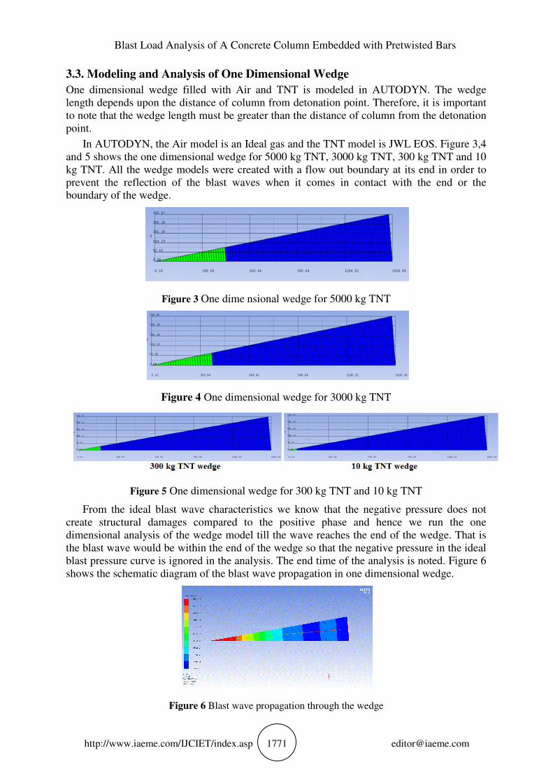
3.3. Modeling and Analysis of One Dimensional Wedge
One dimensional wedge filled with Air and TNT is modeled in AUTODYN. The wedge
length depends upon the distance of column from detonation point. Therefore, it is important
to note that the wedge length must be greater than the distance of column from the detonation
point.
In AUTODYN, the Air model is an Ideal gas and the TNT model is JWL EOS. Figure 3,4
and 5 shows the one dimensional wedge for 5000 kg TNT, 3000 kg TNT, 300 kg TNT and 10
kg TNT. All the wedge models were created with a flow out boundary at its end in order to
prevent the reflection of the blast waves when it comes in contact with the end or the
boundary of the wedge.
Figure 3 One dime nsional wedge for 5000 kg TNT
Figure 4 One dimensional wedge for 3000 kg TNT
Figure 5 One dimensional wedge for 300 kg TNT and 10 kg TNT
From the ideal blast wave characteristics we know that the negative pressure does not
create structural damages compared to the positive phase and hence we run the one
dimensional analysis of the wedge model till the wave reaches the end of the wedge. That is
the blast wave would be within the end of the wedge so that the negative pressure in the ideal
blast pressure curve is ignored in the analysis. The end time of the analysis is noted. Figure 6
shows the schematic diagram of the blast wave propagation in one dimensional wedge.
Figure 6 Blast wave propagation through the wedge

AnuSneha John and Dr. Nivin Philip
http://www.iaeme.com/IJCIET/index.asp 1772 [email protected]
3.4. Modeling Air box and Remapping
We import the column model into AUTODYN by linking the AUTODYN with the Explicit
Dynamics. In AUTODYN, an air box was created around the column to act as the medium to
transport the blast wave to the column. The size of the air box is 2000 mm width, 2000 mm
depth and 4000 mm height. The box is placed in such a way that the column is located at the
centre of the box. The analysed one dimensional wedge is remapped to one of the vertex of
the air box. And thus the one dimensional air and blast wave get transformed into three
dimension. The blast analysis starts from the end time of the one dimensional analysis of
wedge.
Column is a Lagrangian meshed element whereas Air is a Euler domain. Therefore,
Lagrangian – Euler interactions has to be provided which is done by defining the fully
coupled option between the air domain and the column. This makes the Lagrangian mesh to
interact dynamically with the Euler mesh. Also the cycle limit as well as the time limit should
be defined to set the analysis limit.
3.5. Boundary Conditions
The boundary condition provided for the column was fixed-fixed end condition. Therefore,
both the ends are restricted to rotations and translations. This is done by arresting the velocity
in the axial direction, so that the column does not move in the axial direction. Around the air
domain a boundary condition of flow out has been provided to prevent the blast wave
reflections when they come in contact with the end faces.
Figure 7 (a) Fixed End Condition of Column and (b) Flowout Boundary of Air box
3.6. Blast Analysis
When the blast energy got filled in the entire air box, the kinetic energy of the air in the box
diminishes to zero. The analysis was continued till the column fails or the kinetic energy
absorbed in the column diminishes. Once the absorbed energy in the column started falling,
there won’t be much distinguishable damages to the column.
4. RESULTS
4.1. 5000 kg TNT Blast
In this case, the weight of the TNT is 5000 kg. Figure 8 shows the kinetic energy variation
with respect to time of the air medium and it resembles ideal blast curve.

Blast Load Analysis of A Concrete Column Embedded with Pretwisted Bars
http://www.iaeme.com/IJCIET/index.asp 1773 [email protected]
Figure 8 Kinetic Energy – Time Graph of Air Domain for 5000 kg TNT
The maximum kinetic energy of concrete is 1.5×10¹¹
Jµ at 1.5 ms.The kinetic energy
absorbed by concrete at 0.45 ms is nearly 0.25×10¹⁰
Jµ (From Figure 9). After 7.1 ms, it
drops and thereafter there is not much effect of kinetic energy on the column.The highest
amount of kinetic energy absorbed by the steel bars is 1.3×10¹⁰
Jµ at 5 ms (From Figure 9).
The column fails at 7.3 ms as shown in Figure 10.
Figure 9 Absorbed Kinetic Energy in Concrete and Steel
Figure 10 Failure Pattern for 5000 kg TNT at 7.3 ms
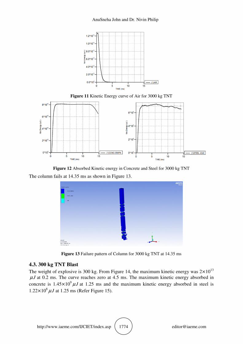
4.2. 3000 kg TNT Blast
The weight of explosive is 3000 kg. The maximum kinetic energy in the air domain is
1.3×10¹⁴
Jµ at 0.2 ms (Refer Figure 11).The maximum kinetic energy absorbed in concrete is
8×10¹⁰
Jµ at 2 ms. The maximum absorbed kinetic energy is 7.2×10⁹
Jµ at 6 ms (Refer
Figure 12).
AnuSneha John and Dr. Nivin Philip
http://www.iaeme.com/IJCIET/index.asp 1774 [email protected]
Figure 11 Kinetic Energy curve of Air for 3000 kg TNT
Figure 12 Absorbed Kinetic energy in Concrete and Steel for 3000 kg TNT
The column fails at 14.35 ms as shown in Figure 13.
Figure 13 Failure pattern of Column for 3000 kg TNT at 14.35 ms
4.3. 300 kg TNT Blast
The weight of explosive is 300 kg. From Figure 14, the maximum kinetic energy was 2×10¹³
Jµ at 0.2 ms. The curve reaches zero at 4.5 ms. The maximum kinetic energy absorbed in
concrete is 1.45×10⁹
Jµ at 1.25 ms and the maximum kinetic energy absorbed in steel is
1.22×10⁸
Jµ at 1.25 ms (Refer Figure 15).

Blast Load Analysis of A Concrete Column Embedded with Pretwisted Bars
http://www.iaeme.com/IJCIET/index.asp 1775 [email protected]
Figure 14 Kinetic Energy of Air for 300 kg TNT
The concrete column at 15.48 ms is shown in Figure 16. Since the kinetic energy absorbed is
diminished, further damage of the column is not possible. Therefore, the column survives the
300 kg blast with minimum damage.
Figure 15 Kinetic energy absorbed in Concrete and Steel for 300 kg TNT
Figure 16 Column at 15.48 ms
4.4. 10 kg TNT blast
The maximum kinetic energy was 16×1010
Jµ at 0.2 ms. The curve reaches zero at 8 ms. The
maximum kinetic energy absorbed in concrete is 1.4×10⁷
Jµ at 3 ms and the maximum
absorbed kinetic energy in steel is 1.22×10⁶
Jµ at 3 ms (Refer Figure 18). The column at
10.25 ms is shown in Figure 19. Thus, the column can withstand the 10 kg TNT blast.

AnuSneha John and Dr. Nivin Philip
http://www.iaeme.com/IJCIET/index.asp 1776 [email protected]
Figure 17 Kinetic Energy of Air for 10 kg TNT
Figure 18 Kinetic energy absorbed in Concrete and Steel for 10 kg TNT
Figure 19 Column at 10.25 ms
5. CONCLUSIONS
From the results of blast analysis we can conclude that the pretwisted bar embedded concrete
column for 5000 kg TNT does not show any kind of resistance against the force. The failure
of the column was observed at 7.3ms. 3000 kg TNT blast on the concrete column with
pretwisted bars also resulted in the failure of the column at a very fast rate. The failure of the
column was at 14.35ms. The column responded differently to the 300 kg TNT blast. The

Blast Load Analysis of A Concrete Column Embedded with Pretwisted Bars
http://www.iaeme.com/IJCIET/index.asp 1777 [email protected]
kinetic energy that was absorbed by the column get diminished so fast, so that the column
does not fail under 300 kg TNT. For the 10 kg TNT blast, the column was found to be safe,
does not even yielded. The kinetic energy that was absorbed by the column was diminished
fastly.
Therefore we can say the concrete column with pretwisted bars are safe under 300 kg and
below TNT blast loads. As the weight of TNT increases, the time for total damage decreases.
The study considered only unloaded column for blast analysis.
REFERENCES
[1] Samer A. Barakatand Farid H. Abed.Experimental Investigation of the Axial capacity of
Inelastically Pretwisted steel bars. Journal of Engineering Mechanics,136(8), 2010, pp.
1028-1035.
[2] Farid H. Abed, Mohammad H. AlHamaydehandSamer A. Barakat. Non-linear Finite
Element Analysis of Buckling capacity of pretwisted steel bars. Journal of Engineering
Mechanics, 139(7), 2013, pp. 791-801.
[3] Ahmed Samir Eisa. Finite Element Analysis of Reinforced Concrete Columns under
different range of Blast Loads. International Journal of Civil and Structural Engineering,
5(2), 2014, pp. 155-164.
[4] Mohammed Alias Yusof, RafikaNorhidayuRosdi, NorazmanMohamadNor, Ariffin
Ismail, Muhammad AzaniYahya and Ng Choy Peng. Simulation of Reinforced Concrete
Blast Wall Subjected to Air Blast Loading. Journal of Asian Scientific Research, 4(9),
2014, pp. 522-533.
[5] Fangui Zhang, Chengqing Wu, Hongwei Wang and Yun Zhou. Numerical Simulation of
Concrete filled Steel tube Columns against Blast Loads. Thin Walled Structures, 92, 2015,
pp. 82-92.
[6] Amr A. Nassr, A. GhaniRazaqpur, Michael J. Tait, Manuel Campidelli and Simon Foo.
Experimental Performance of Steel Beams under Blast Loading. Journal of Performance
of Constructed Facilities, 26(5), 2012, pp. 600-619.
[7] XiaoliBao and Bing Li. Residual strength of blast damaged reinforced concrete columns.
International Journal of Impact Engineering, 37, 2010, pp. 295-308.
[8] Ke Chiang Wu, Bing Li and Keh-Chyuan Tsai. Residual axial compression capacity of
localized blast damaged RC columns. International Journal of Impact Engineering, 38,
2011, pp. 29-40.
[9] NeetuJha and B. S. Kiran Kumar. Air Blast Validation using ANSYS/AUTODYN.
International Journal of Engineering Research and Technology, 3(1), 2014, pp. 1794-
1797.
[10] VasilisKarlos and George Solomos. Calculation of Bast Loads for Application to
Structural Components. JRC Technical Reports, 2013.
[11] Chengqing Wu and Hong Hao. Modeling of Simultaneous Ground Shock and Air Blast
Pressure on nearby Structures from Surface Explosion. International Journal of Impact
Engineering, 31, 2005, pp. 699-717.
[12] Guowei Ma, Hong Hao and Yingxin Zhou. Assessment of Structure Damage to Blasting
Induced Ground Motions. 22, 2000, pp.1378-1389.
[13] Kinney G. F and Graham K. J. Explosive Shocks in Air. Springer, 2nd
edition, Berlin.
1985.