blackrock research assemblies
TRANSCRIPT
Blackrock Research Assemblies Instruction for Use (IFU)
Electrophysiology, Simplified.
LB-0514 2.00 Blackrock Research Assemblies IFU
© 2014 Blackrock Microsystems™, LLC
p0
Blackrock Research Assemblies
Blackrock Microsystems, LLC
630 Komas Drive · Suite 200 Salt Lake City · UT 84108
T: (801) 582-5533 www.blackrockmicro.com
Blackrock Research Assemblies
Instruction for Use (IFU)
Electrophysiology, Simplified.
LB-0514 2.00 Blackrock Research Assemblies IFU
© 2014 Blackrock Microsystems™, LLC
p1
Blackrock Research Assemblies
Instruction for Use (IFU)
Electrophysiology, Simplified.
LB-0514 2.00 Blackrock Research Assemblies IFU
© 2014 Blackrock Microsystems™, LLC
p2
1. Introduction
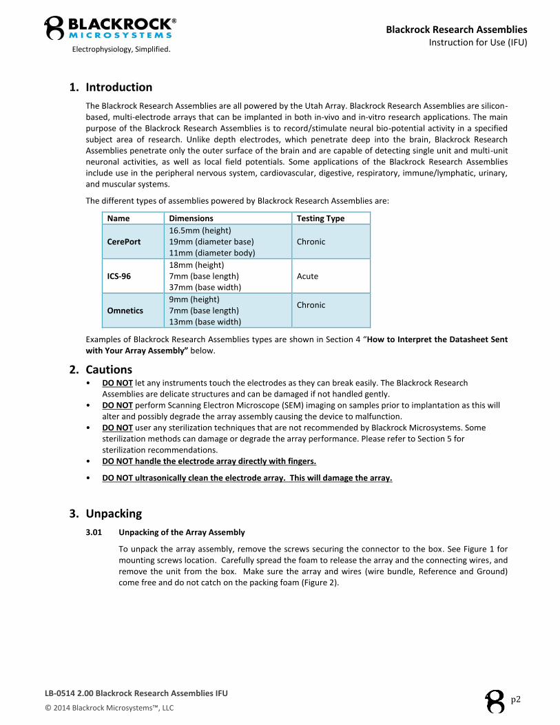
The Blackrock Research Assemblies are all powered by the Utah Array. Blackrock Research Assemblies are silicon-based, multi-electrode arrays that can be implanted in both in-vivo and in-vitro research applications. The main purpose of the Blackrock Research Assemblies is to record/stimulate neural bio-potential activity in a specified subject area of research. Unlike depth electrodes, which penetrate deep into the brain, Blackrock Research Assemblies penetrate only the outer surface of the brain and are capable of detecting single unit and multi-unit neuronal activities, as well as local field potentials. Some applications of the Blackrock Research Assemblies include use in the peripheral nervous system, cardiovascular, digestive, respiratory, immune/lymphatic, urinary, and muscular systems.
The different types of assemblies powered by Blackrock Research Assemblies are:
Name Dimensions Testing Type
CerePort 16.5mm (height) 19mm (diameter base) 11mm (diameter body)
Chronic
ICS-96 18mm (height) 7mm (base length) 37mm (base width)
Acute
Omnetics 9mm (height) 7mm (base length) 13mm (base width)
Chronic
Examples of Blackrock Research Assemblies types are shown in Section 4 “How to Interpret the Datasheet Sent with Your Array Assembly” below.
2. Cautions • DO NOT let any instruments touch the electrodes as they can break easily. The Blackrock Research
Assemblies are delicate structures and can be damaged if not handled gently. • DO NOT perform Scanning Electron Microscope (SEM) imaging on samples prior to implantation as this will
alter and possibly degrade the array assembly causing the device to malfunction. • DO NOT user any sterilization techniques that are not recommended by Blackrock Microsystems. Some
sterilization methods can damage or degrade the array performance. Please refer to Section 5 for sterilization recommendations.
• DO NOT handle the electrode array directly with fingers.
• DO NOT ultrasonically clean the electrode array. This will damage the array.
3. Unpacking
3.01 Unpacking of the Array Assembly
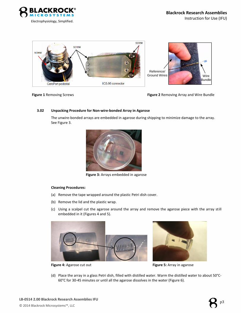
To unpack the array assembly, remove the screws securing the connector to the box. See Figure 1 for mounting screws location. Carefully spread the foam to release the array and the connecting wires, and remove the unit from the box. Make sure the array and wires (wire bundle, Reference and Ground) come free and do not catch on the packing foam (Figure 2).
Blackrock Research Assemblies
Instruction for Use (IFU)
Electrophysiology, Simplified.
LB-0514 2.00 Blackrock Research Assemblies IFU
© 2014 Blackrock Microsystems™, LLC
p3
Wire
Bundle
Reference/
Ground Wires
Figure 1 Removing Screws Figure 2 Removing Array and Wire Bundle
3.02 Unpacking Procedure for Non-wire-bonded Array in Agarose
The unwire-bonded arrays are embedded in agarose during shipping to minimize damage to the array. See Figure 3.
Figure 3: Arrays embedded in agarose
Cleaning Procedures:
(a) Remove the tape wrapped around the plastic Petri dish cover.
(b) Remove the lid and the plastic wrap.
(c) Using a scalpel cut the agarose around the array and remove the agarose piece with the array still embedded in it (Figures 4 and 5).
Figure 4: Agarose cut out Figure 5: Array in agarose
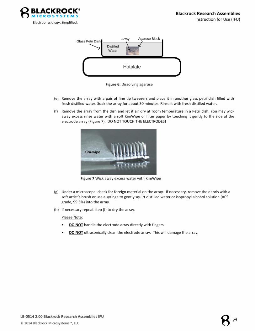
(d) Place the array in a glass Petri dish, filled with distilled water. Warm the distilled water to about 50°C-
60°C for 30-45 minutes or until all the agarose dissolves in the water (Figure 6).
Blackrock Research Assemblies
Instruction for Use (IFU)
Electrophysiology, Simplified.
LB-0514 2.00 Blackrock Research Assemblies IFU
© 2014 Blackrock Microsystems™, LLC
p4
Glass Petri Dish
Hotplate
Distilled
Water
Agarose BlockArray
Figure 6: Dissolving agarose
(e) Remove the array with a pair of fine tip tweezers and place it in another glass petri dish filled with fresh distilled water. Soak the array for about 30 minutes. Rinse it with fresh distilled water.
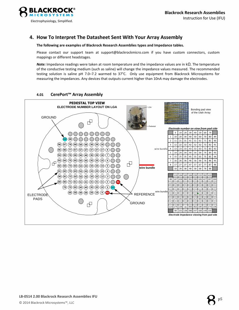
(f) Remove the array from the dish and let it air dry at room temperature in a Petri dish. You may wick away excess rinse water with a soft KimWipe or filter paper by touching it gently to the side of the electrode array (Figure 7). DO NOT TOUCH THE ELECTRODES!
Figure 7 Wick away excess water with KimWipe
(g) Under a microscope, check for foreign material on the array. If necessary, remove the debris with a soft artist’s brush or use a syringe to gently squirt distilled water or isopropyl alcohol solution (ACS grade, 99.5%) into the array.
(h) If necessary repeat step (f) to dry the array.
Please Note:
• DO NOT handle the electrode array directly with fingers.
• DO NOT ultrasonically clean the electrode array. This will damage the array.
Blackrock Research Assemblies
Instruction for Use (IFU)
Electrophysiology, Simplified.
LB-0514 2.00 Blackrock Research Assemblies IFU
© 2014 Blackrock Microsystems™, LLC
p5
4. How To Interpret The Datasheet Sent With Your Array Assembly
The following are examples of Blackrock Research Assemblies types and Impedance tables.
Please contact our support team at [email protected] if you have custom connectors, custom mappings or different headstages.
Note: Impedance readings were taken at room temperature and the impedance values are in kΩ. The temperature of the conductive testing medium (such as saline) will change the impedance values measured. The recommended testing solution is saline pH 7.0–7.2 warmed to 37°C. Only use equipment from Blackrock Microsystems for measuring the impedances. Any devices that outputs current higher than 10nA may damage the electrodes.
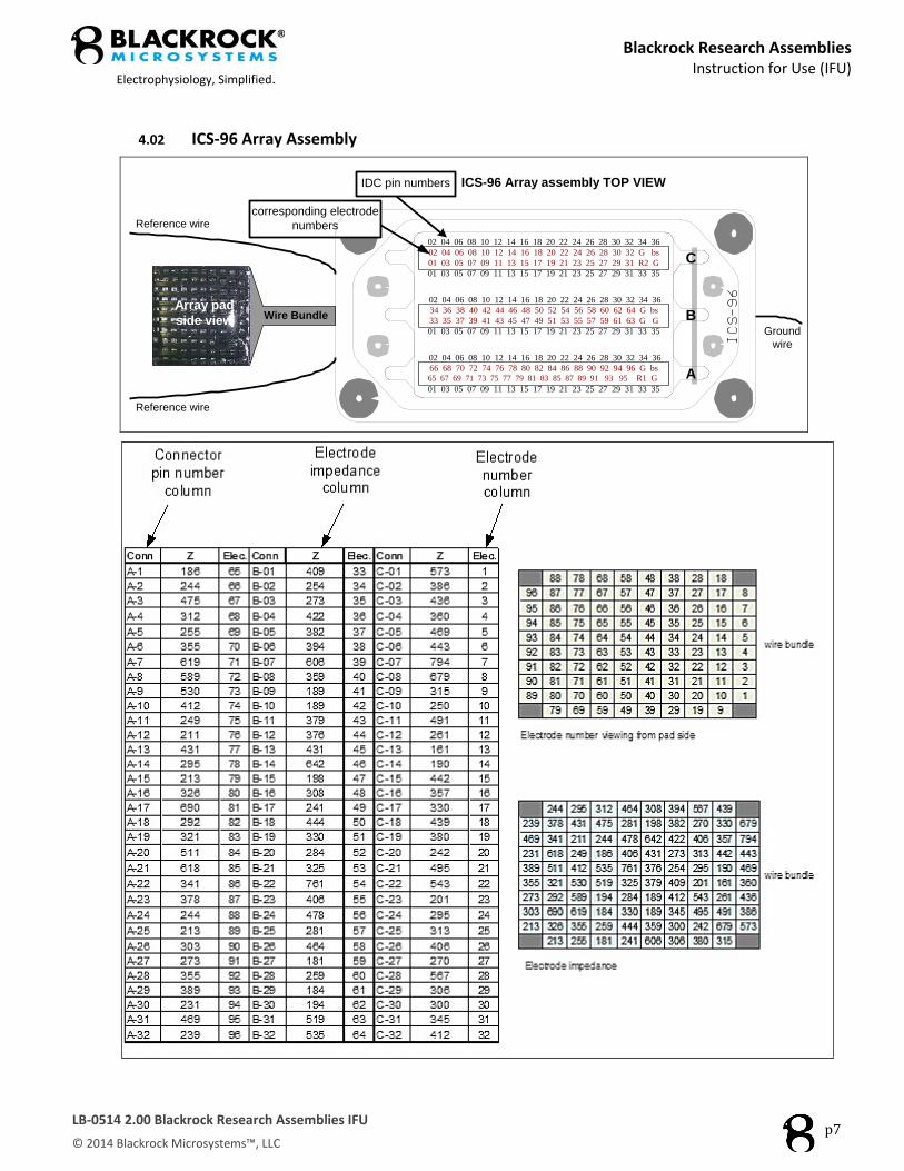
4.01 CerePort™ Array Assembly
PEDESTAL TOP VIEWELECTRODE NUMBER LAYOUT ON LGA
29
30
31
32
33
34
35
36
37
38
19
20
21
22
23
24
25
26
27
28
9
10
11
12
13
14
15
16
17
18
R2
11
2
3
4
5
6
7
8
G1
R189
90
91
92
93
94
95
96
79
80
81
82
83
84
85
86
87
G2
69
70
71
72
73
74
75
76
77
78
88
59
60
61
62
63
64
65
66
67
68
49
50
51
52
53
54
55
56
57
58
39
40
41
42
43
44
45
46
47
48
GROUND
REFERENCE
GROUND
ELECTRODE
PADS
Electrode number on view from pad side
9 19 29 39 49 59 69 79
1 10 20 30 40 50 60 70 80 89
2 11 21 31 41 51 61 71 81 90
3 12 22 32 42 52 62 72 82 91
wire bundle 4 13 23 33 43 53 63 73 83 92
5 14 24 34 44 54 64 74 84 93
6 15 25 35 45 55 65 75 85 94
7 16 26 36 46 56 66 76 86 95
8 17 27 37 47 57 67 77 87 96
18 28 38 48 58 68 78 88
119 194 165 184 239 215 392 419
88 167 436 390 391 330 326 427 397 269
120 242 298 324 334 283 280 309 329 350
143 193 158 213 425 219 274 366 278 210
wire bundle 155 175 183 169 239 211 290 442 317 275
150 205 238 241 442 266 309 470 286 173
117 170 191 169 346 212 365 452 306 171
124 622 628 245 429 339 226 302 216 161
114 175 136 1111 355 352 190 193 174 136
99 101 138 286 247 168 149 155
Electrode Impedance viewing from pad side
wire bundle
Pedestal
LGA
Bonding pad view
of the Utah Array

Blackrock Research Assemblies
Instruction for Use (IFU)
Electrophysiology, Simplified.
LB-0514 2.00 Blackrock Research Assemblies IFU
© 2014 Blackrock Microsystems™, LLC
p6
CerePort ™ Array Assembly (Cont.)
Blackrock Research Assemblies
Instruction for Use (IFU)
Electrophysiology, Simplified.
LB-0514 2.00 Blackrock Research Assemblies IFU
© 2014 Blackrock Microsystems™, LLC
p7
4.02 ICS-96 Array Assembly
Reference wire
Reference wire
Wire BundleArray pad
side viewGround
wire
ICS-96 Array assembly TOP VIEWIDC pin numbers
C
B
A
02 04 06 08 10 12 14 16 18 20 22 24 26 28 30 32 34 36
02 04 06 08 10 12 14 16 18 20 22 24 26 28 30 32 G bs
01 03 05 07 09 11 13 15 17 19 21 23 25 27 29 31 R2 G
01 03 05 07 09 11 13 15 17 19 21 23 25 27 29 31 33 35
02 04 06 08 10 12 14 16 18 20 22 24 26 28 30 32 34 36
34 36 38 40 42 44 46 48 50 52 54 56 58 60 62 64 G bs
33 35 37 39 41 43 45 47 49 51 53 55 57 59 61 63 G G
01 03 05 07 09 11 13 15 17 19 21 23 25 27 29 31 33 35
02 04 06 08 10 12 14 16 18 20 22 24 26 28 30 32 34 36
66 68 70 72 74 76 78 80 82 84 86 88 90 92 94 96 G bs
65 67 69 71 73 75 77 79 81 83 85 87 89 91 93 95 R1 G
01 03 05 07 09 11 13 15 17 19 21 23 25 27 29 31 33 35
corresponding electrode
numbers
Blackrock Research Assemblies
Instruction for Use (IFU)
Electrophysiology, Simplified.
LB-0514 2.00 Blackrock Research Assemblies IFU
© 2014 Blackrock Microsystems™, LLC
p8
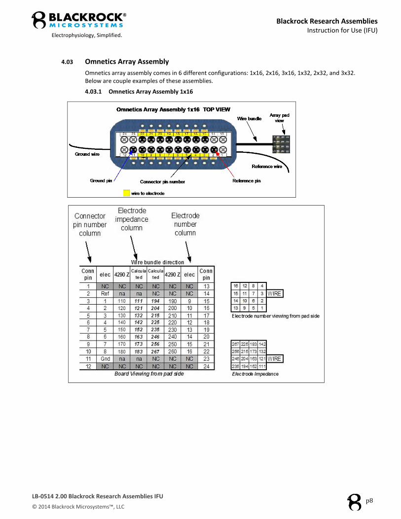
4.03 Omnetics Array Assembly
Omnetics array assembly comes in 6 different configurations: 1x16, 2x16, 3x16, 1x32, 2x32, and 3x32. Below are couple examples of these assemblies.
4.03.1 Omnetics Array Assembly 1x16

Blackrock Research Assemblies
Instruction for Use (IFU)
Electrophysiology, Simplified.
LB-0514 2.00 Blackrock Research Assemblies IFU
© 2014 Blackrock Microsystems™, LLC
p9
4.03.2 Omnetics Array Assembly 1x32
Ground 2
Reference 2
Omnetics Array Assembly 1x32 TOP VIEWReference
Ground
2122232425262728293031323334353637383940
1234567891011121314151617181920
Ground
Reference
Wire bundle
Array pad
view
Reference 1
Ground 1
Connector pin number wire to electrode
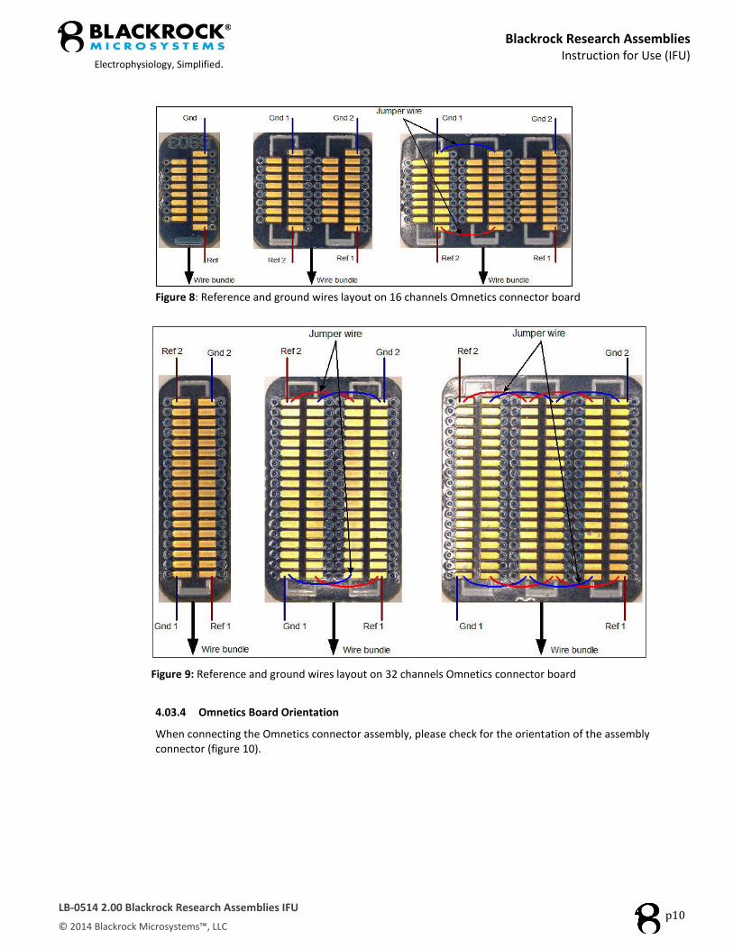
4.03.3 Reference and ground wires on Omnetics Array Assembly Board (Viewing From Pad Side)
Figures below show reference and ground wires layout on Omnetics assembly boards (figures 8 and 9).
Blackrock Research Assemblies
Instruction for Use (IFU)
Electrophysiology, Simplified.
LB-0514 2.00 Blackrock Research Assemblies IFU
© 2014 Blackrock Microsystems™, LLC
p10
Figure 8: Reference and ground wires layout on 16 channels Omnetics connector board
Figure 9: Reference and ground wires layout on 32 channels Omnetics connector board
4.03.4 Omnetics Board Orientation
When connecting the Omnetics connector assembly, please check for the orientation of the assembly connector (figure 10).

Blackrock Research Assemblies
Instruction for Use (IFU)
Electrophysiology, Simplified.
LB-0514 2.00 Blackrock Research Assemblies IFU
© 2014 Blackrock Microsystems™, LLC
p11
Figure 10: Omnetics Array Assembly
5. Sterilization
5.01 Blackrock recommends ETO sterilization according to the protocol below (Table 1). Do not use other methods of sterilization, as these may damage the integrity of the array. Contact Blackrock Support ([email protected]) with additional questions.
Table 1: ETO Processing Parameters
Preconditioning
Set Point Minimum Maximum
Temperature: 110°F 105°F 120°F
Relative Humidity: 65% 45% 75%
Time: 24Hrs 0Min 24Hrs 0Min 72Hrs 0Min
Process Temperature 125°F 115°F 135°F
Vacuum A Approx. Rate: 0.7”/min
Evacuate To: 5.8 inHgA 5.3 inHgA 6.3 inHgA
Nitrogen Dilution Approx. Rate: 0.7”/min
Humidity Pressure Rise: inHgA inHgA inHgA
N2 Inject To: 25.3 inHgA 24.8 inHgA 25.8inHgA
Evacuate To: 5.8 inHgA 5.3 inHgA 6.3 inHgA
Humidification Approx. Rate: 0.7”/min
Pressure Rise: 1.4 inHgA 0.9 inHgA 1.9 inHgA
Humidity Dwell Dwell Time: 30 Min 29 Min 35 Min
Maintain Pressure At: 7.2 inHgA 6.7 inHgA 7.7 inHgA
Gas A Approx. Rate: 0.7”/min
Gas Pressure-Inject To: 17.9 inHgA 17.4 inHgA 18.4 inHgA
Gas Dwell
Maintain Pressure: Yes
Sterilant / Inert: Sterilant
Temperature: 125°F 120°F 130°F
Time: 4hrs 0min 3hrs 59min 4hrs 40min
At: 17.9 inHgA 17.4 inHgA 18.4 inHgA
After Vacuum Approx. Rate: 0.7”/min
Evacuate To: 7.8 inHgA 7.3 inHgA 9.3 inHgA
Vacuum Hold Time: 1Hrs 00Min 0Hrs 59Min 1Hrs 4Min
Gas Wash A
Inject Type: Inert
Approx. Rate: 0.7”/min
Inject To: 24.8 inHgA 24.3 inHgA 25.3inHgA
Evacuate To: 5.8 inHgA 5.3 inHgA 7.3 inHgA
Vacuum Hold Time: 30Min 29 Min 34 Min
Number of Cycles 0 (1 total)
Gas Wash B Inject To: 24.8 inHgA 24.3 inHgA 25.3inHgA
Blackrock Research Assemblies
Instruction for Use (IFU)
Electrophysiology, Simplified.
LB-0514 2.00 Blackrock Research Assemblies IFU
© 2014 Blackrock Microsystems™, LLC
p12
Inject Type: Inert
Approx. Rate: 0.7”/min
Evacuate To: 5.8 inHgA 5.3 inHgA 6.3 inHgA
Number of Cycles 2 (3 total)
Release Approx. Rate: 0.7" / Min
Release To: 24.8 inHgA inHgA inHgA
Heated Aeration Temperature: 110°F 100°F 135°F
Time: 36 Hrs 36 Hrs N/A
6. Cleaning and Storage for Arrays Used in Acute Preparations
6.01 Remove the array from the subject and immediately place it in clean distilled water until it will be cleaned.
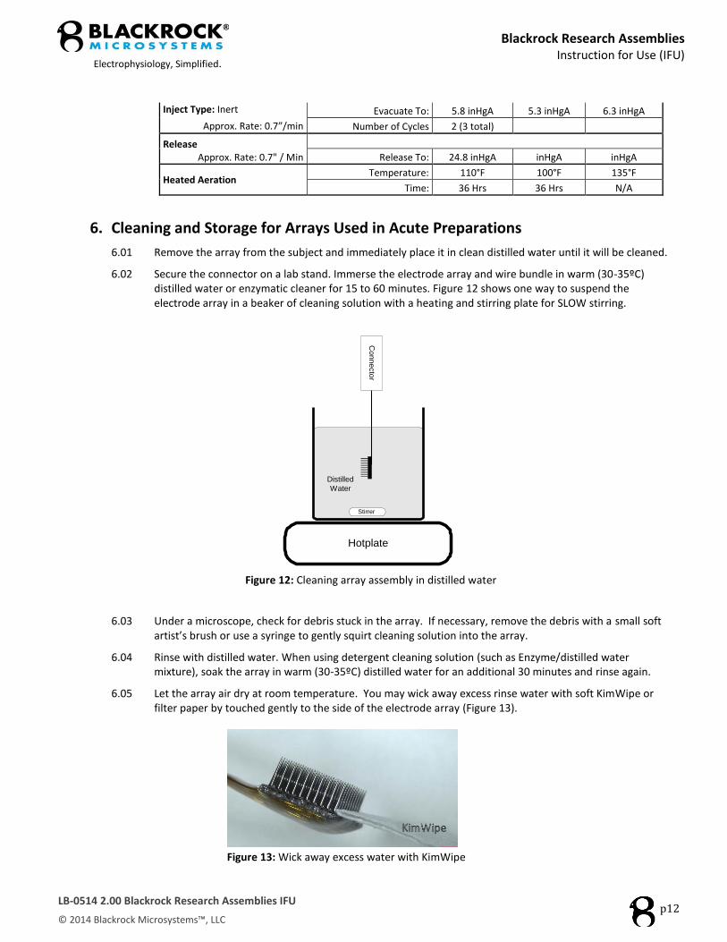
6.02 Secure the connector on a lab stand. Immerse the electrode array and wire bundle in warm (30-35ºC) distilled water or enzymatic cleaner for 15 to 60 minutes. Figure 12 shows one way to suspend the electrode array in a beaker of cleaning solution with a heating and stirring plate for SLOW stirring.
Hotplate
Distilled
Water
Connecto
r
Stirrer
Figure 12: Cleaning array assembly in distilled water
6.03 Under a microscope, check for debris stuck in the array. If necessary, remove the debris with a small soft artist’s brush or use a syringe to gently squirt cleaning solution into the array.
6.04 Rinse with distilled water. When using detergent cleaning solution (such as Enzyme/distilled water mixture), soak the array in warm (30-35ºC) distilled water for an additional 30 minutes and rinse again.
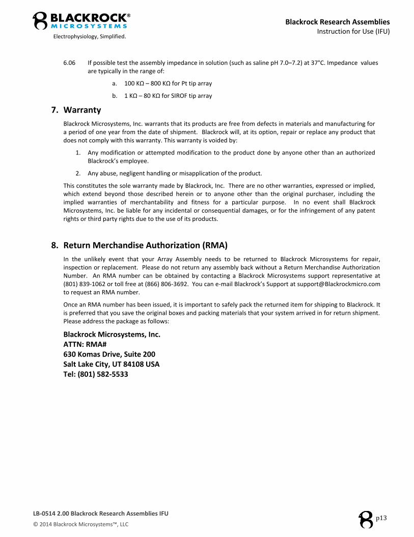
6.05 Let the array air dry at room temperature. You may wick away excess rinse water with soft KimWipe or filter paper by touched gently to the side of the electrode array (Figure 13).
Figure 13: Wick away excess water with KimWipe
Blackrock Research Assemblies
Instruction for Use (IFU)
Electrophysiology, Simplified.
LB-0514 2.00 Blackrock Research Assemblies IFU
© 2014 Blackrock Microsystems™, LLC
p13
6.06 If possible test the assembly impedance in solution (such as saline pH 7.0–7.2) at 37°C. Impedance values are typically in the range of:
a. 100 KΩ – 800 KΩ for Pt tip array
b. 1 KΩ – 80 KΩ for SIROF tip array
7. Warranty
Blackrock Microsystems, Inc. warrants that its products are free from defects in materials and manufacturing for a period of one year from the date of shipment. Blackrock will, at its option, repair or replace any product that does not comply with this warranty. This warranty is voided by:
1. Any modification or attempted modification to the product done by anyone other than an authorized Blackrock’s employee.
2. Any abuse, negligent handling or misapplication of the product.
This constitutes the sole warranty made by Blackrock, Inc. There are no other warranties, expressed or implied, which extend beyond those described herein or to anyone other than the original purchaser, including the implied warranties of merchantability and fitness for a particular purpose. In no event shall Blackrock Microsystems, Inc. be liable for any incidental or consequential damages, or for the infringement of any patent rights or third party rights due to the use of its products.
8. Return Merchandise Authorization (RMA)
In the unlikely event that your Array Assembly needs to be returned to Blackrock Microsystems for repair, inspection or replacement. Please do not return any assembly back without a Return Merchandise Authorization Number. An RMA number can be obtained by contacting a Blackrock Microsystems support representative at (801) 839-1062 or toll free at (866) 806-3692. You can e-mail Blackrock’s Support at [email protected] to request an RMA number.
Once an RMA number has been issued, it is important to safely pack the returned item for shipping to Blackrock. It is preferred that you save the original boxes and packing materials that your system arrived in for return shipment. Please address the package as follows:
Blackrock Microsystems, Inc. ATTN: RMA# 630 Komas Drive, Suite 200 Salt Lake City, UT 84108 USA Tel: (801) 582-5533