safe operation of critical assemblies and research reactors 1971
TRANSCRIPT

I A E A
S A F E T Y S T A N D A R D S
S A F E T Y SERIES
N o.35
Safe Operation of Critical Assemblies and Research Reactors
1971 Edition
Code of Practicesponsored by
IAEA and W H O
and Technical Appendix
IN T E R N A T IO N A L A T O M IC E N E R G Y A G E N C Y
V IE N N A , 1971
This publication is no longer valid Please see http://www-ns.iaea.org/standards/

This publication is no longer valid Please see http://www-ns.iaea.org/standards/

SAFE OPERATION OF CRITICAL ASSEMBLIES
AND RESEARCH REACTORS 1971 EDITION
This publication is no longer valid Please see http://www-ns.iaea.org/standards/

This publication is no longer valid Please see http://www-ns.iaea.org/standards/
S A F E T Y S E R IE S N o. 35
SAFE OPERATION OF CRITICAL ASSEMBLIES
AND RESEARCH REACTORS 1971 EDITION
CODE OF PRACTICE
SPO N SO RED BY THE IN TERN A TIO N AL ATOM IC ENERGY AGENCY
AND THE WORLD HEALTH O RG A N IZA TIO N
AND TECHNICAL APPENDIX
IN TERN A TIO N AL ATOM IC EN ERGY AGENCY VIENNA, 1971
This publication is no longer valid Please see http://www-ns.iaea.org/standards/

TH IS SAFETY SERIES WILL ALSO BE PUBLISHED IN FRENCH, RUSSIAN AND SPANISH
SAFE O PERA TIO N OF CRITICAL ASSEMBLIES AND RESEARCH REA CTO RS, 1971 ED ITIO N
IAEA, VIENNA, 1971 STI/PU B/ 225
Printed by the IAEA in Austria March 1971
This publication is no longer valid Please see http://www-ns.iaea.org/standards/

FOREWORDThis book is in two parts. The first is a Code of Practice for
the Safe Operation of Critical Assemblies and Research Reactors, prepared as a result of a meeting of experts which took place in Vienna on 20—24 May 1968.
The Code has been prepared by the International Atomic Energy Agency in co-operation with the World Health Organization, and its publication is sponsored by both organizations. In addition, the Code was approved by the Board of Governors of the International Atomic Energy Agency on 16 December 1968 as part of the Agency’s safety standards, which are applied to operations undertaken by Member States with the assistance of the Agency. The Board, in approving the publication of the present book, also recommended Member States to take the Code into account in the formulation of national regulations and recommendations.
The second part of the book is a Technical Appendix to give information and illustrative samples that would be helpful in implementing the Code of Practice. The Agency is very grateful to Dr. Jam es Cox of Oak Ridge National Laboratory for its preparation. This second part, although published under the same cover, is not part of the Code.
An extensive Bibliography, amplifying the Technical Appendix, is included at the end. This has also been compiled by D r. Cox.
This publication is no longer valid Please see http://www-ns.iaea.org/standards/

This publication is no longer valid Please see http://www-ns.iaea.org/standards/

C O N T E N T S
Introduction........................................................................................................ 1G eneral..................................................................................................... 1Purpose and Scope............................................................................... 1
1. External supervision.......................................................................... . 22. Safety rep orts.......................................................................................... 33. Limits and conditions.......................................................................... 44. Experiments and modifications........................................................ 65. Com m issioning...................................................................................... 76. Operating instructions.............................................. .......................... 77. Records and reports.............................................. ................. ............ 88. Management........................................... ................................................ 99. Maintenance................................................................................... ........ 10
10. Periodic testing and inspection ........................................................ 1011. Radiological protection........................................................................ 1112. Emergency precautions........................................................................ 12
PART II. TECHNICAL A P P EN D IX ...................................................... 13
Preface.................................................................................................................... 13D efinitions........................................................................................................... 13
Critical assemblies............................................................... ............................. 15
Subcritical assemblies......................................................................... 15Critical assembly hazards................................................................... 15General safety considerations.......................................................... 17Reactivity considerations................................................................... 22Neutron source..................................................................................... 30Commissioning and operation......................................................... 32Procedures for critical experiments................................................ 34
PART I. CODE OF PRACTICE
This publication is no longer valid Please see http://www-ns.iaea.org/standards/

Research reactors............................................................................................... 39
General safety considerations.......................................................... 39Research reactor hazards................................................................... 40Reactivity additions............................................................................. 44Cooling system s.................................................................................... 45Commissioning..................................................................................... 47Experiment review and approval..................................................... 52
Considerations applying to critical assemblies and research reactors.................................................................................... 63
Safety instrumentation considerations......................................... 63Control-rod considerations............................................................... 78Building and shielding considerations......................................... 85Safety considerations in fuel handling and storage.................. 90Precautions in use of m aterials....................................................... 95Radiological protection....................................................................... 98Procedures.............................................................................................. 100Maintenance........................................................................................... 103Safety com m ittee........................ ......................................................... 106Records..................................................................................................... I l lOrganization.......................................................................................... 113Staff qualifications and training....................................................... 116Emergencies......... ................................................................................. 120
B ibliography........................................................................................................ 129
This publication is no longer valid Please see http://www-ns.iaea.org/standards/

PART I CODE OF PRACTICE
IN TR O D U C TIO N
GENERAL
1. The safe operation of critical assemblies and research reactors postulates proper design, construction and management o f such assemblies and reactors.
2. Under the present Code of Practice for the Safe Operation of Critical Assemblies and Research Reactors, it is recommended that documentation dealing with the operation and experimental use of such assemblies and reactors and including safety analyses be prepared and submitted for review and approval to a regulatory body. Operation would be authorized on the understanding
, that it would comply with limits and conditions designed to ensure safety. The code may be subject to revision in the light of experience.
3. In the code the word "reactor” is used to mean “critical assembly” or "research reactor”. The code covers a wide range of reactor types which give rise to a variety of safety problems and, in many cases, a recommendation must be interpreted according to the type of reactor concerned. In such cases the words "adequate” and "appropriate” are used to mean "adequate (or appropriate) for the type of reactor under consideration”.
4. Recommendations relating to some of the topics dealt with in the code are set forth in the manual entitled "Safe Operation of Critical Assemblies and Research Reactors” (IAEA Safety Series N o .4 ) , which, however, does not cover fast critical assemblies and research reactors designed to operate continuously at high power.
PU RPO SE AND SCOPE
5. The recommendations in the code are designed to protect the general public and the reactor personnel from radiation hazards, and the code forms part of the Agency’s Safety Standards and should be followed in operations conducted or assisted by the
1
This publication is no longer valid Please see http://www-ns.iaea.org/standards/

Agency. The code also provides guidance and information to persons and authorities responsible for the operation and experimental use of critical assemblies or research reactors. It sets forth minimum requirements which, it is believed, in the light of experience, must be met in order to achieve safe operation and safe experimental use of critical assemblies and research reactors. It must be clearly understood, however, that fulfilment of those minimum requirements will not necessarily guarantee safe operation.
6. A Government which wishes to enter into an agreement with the Agency concerning the construction or the operation and experimental use of a critical assembly or research reactor will be asked to follow the recommendations in the code. It should be noted, however, that the code does not lay down the methods which should be employed to achieve that end.
7. Although the recommendations in the code are not intended to cover fast critical assemblies and research reactors designed to operate continuously at high power, some of them are applicable to such facilities.
1. EXTERNAL SU PERVISIO N
1.1. The reactor manager is directly responsible for the safe operation of the reactor.
1.2. In discharging its responsibility for public health and safety the Government should ensure that the safety of the reactor is subject to review by a regulatory body independent of the operating organization, or by a body or committee of the operating organization, provided that this body br committee is independent of the reactor operating group.1
1.3. It is essential to the achievement o f their common objective, safe reactor operation, that the relationship between the regulatory body and the operating organization should be based on mutual understanding and respect. Consequendy the operating
1 The regulatory body must discharge responsibilities of a special nature and in different fields. Most existing organizations will have had no previous experience of all tasks involved. It will probably be necessary to establish a new authority and entrust it with special functions. The composition of this body and also its position within the national governmental structure belongs to the discretion of the Government concerned, but should include the authorities responsible for public health and atomic energy.
2
This publication is no longer valid Please see http://www-ns.iaea.org/standards/

organization should regard the regulatory body as a valuable source of constructive criticism and technical and administrative assistance, and the latter should maintain a high level of understanding of the economic and technical problems of the operating organization.
1.4. The following procedures should be followed in the performance of regulatory functions:
(a ) A Safety Report relating to the reactor (see Section 2) should be submitted by the operating organization to the regulatory body for review and approval;
(b ) On the basis o f safety considerations set forth in the Safety Report, the operating organization should submit to the regulatory body for review and approval a document setting out the limits and conditions (see Section 3) in accordance with which, in the interest of safety, operations and experiments are to be conducted. The regulatory body may, however, waive the requirement for submission of a separate limits and conditions document provided that the relevant information is easily identifiable and readily available in the Safety Report;
( c ) The limits and conditions referred to in (b ) above may be revised in the light o f experience. Proposed changes in the limits and conditions should be approved by the regulatory body before their implementation;
(d) Detailed operating instructions (see Section 6 ) should be prepared by the operating group and be in keeping with the limits and conditions referred to in (b ) above;
(e ) Records should be maintained (see Sub-sections 7.1 and 7 .2 ) and be available to the regulatory body; and
( f ) The regulatory body should require that inspection of the reactor be carried out with the frequency necessary to ensure safety. The inspection should be aimed at both the technical and the management aspects o f safety (see Sub-section 10).
2. SAFETY REPO RTS
2.1. Safety Reports should contain information on the site and environment, reactor design information and safety analyses to the extent required by the regulatory body.
3
This publication is no longer valid Please see http://www-ns.iaea.org/standards/

2.2. Preliminary Safety Reports may be submitted to the regulatory body during the early stages of design and construction. A detailed Safety Report should, however, be submitted before operation of the reactor begins.
2.3. A Safety Report should include:
(a ) An adequate description of the reactor and its site and environment;
(b ) A statement of the safety principles governing the design and proposed operation and experimental use of the reactor;
( c ) An adequate description of the methods and procedures used to ensure that appropriate quality control practices will be followed during construction, and that applicable codes and standards will be followed in designing and constructing the reactor;
(d) A safety analysis of the proposed operating instructions containing the detailed information and calculations required to enable the regulatory body to make a full assessment of the safety o f the reactor. The safety analysis should, in particular, include an examination of the probable occurrence and the consequences of serious faults, having regard to all aspects of design, performance and operation; it should also indicate how the limits and conditions which apply to the operation of the reactor were arrived at; and
(e ) An examination of the safety aspects o f any experiment to be carried out in or adjacent to the reactor core.
3. LIM ITS AND C O N D ITIO N S
3.1. Before the operation of the reactor a set of proposed limits and conditions should be submitted to the regulatory body for review and approval. An official copy of the approved limits and conditions2 should be held by the reactor operating group.
2 In some countries provisions governing limits and conditions are not setout in specific documents; the relevant information should, however, be easily identifiable and readily available.
4
This publication is no longer valid Please see http://www-ns.iaea.org/standards/

3.2.
3.3.
3.4.
3.5.
3.6.
3.7.
3.8.
3.9.
The limits and conditions laid down for operation of the reactor should cover organizational and procedural, as well as technical, aspects of operation having a bearing on safety.Limits and conditions as applied to reactors and experiments (see Sub-section 2.3 (e )) should be established which cover the following:
(a ) Safety limits;(b ) Safety system settings where appropriate;(c ) Limiting conditions for safe operation; and(d) Surveillance requirements.
The selection of appropriate values for safety limits and conditions should be based on systematic analysis of the reactor and its environment. These limits and conditions should always be in keeping with the current state of the reactor and technological development.Safety limits are boundary values assigned to important parameters or process variables to provide protection against the uncontrolled release of undue amounts of radioactivity. Such safety limits should generally be defined in terms of maximum or minimum values (as appropriate) within which the variables or parameters should remain.Safety systems settings should be such as would actuate appropriate automatic protective devices to prevent violation of any safety limit. In cases where the limited variable is not directly measured, e.g. fuel temperature, safety system settings for other related variables should be specified as appropriate, to prevent violation of the limit.In specifying safety system settings, the necessary allowances should be made for inaccuracies in the measuring equipment. Such inaccuracies should be minimized during the design and subsequent maintenance of the equipment by taking particular account o f its operating characteristics in the whole range of possible safety system settings.Failure of equipment used for safety system settings should be followed, wherever practicable, by an increase in the safety of the reactor.Where a protective system, designed to ensure that a safety limit is not violated, fails to function as and when required, the situation should be reviewed and evaluated by the reactor
5
This publication is no longer valid Please see http://www-ns.iaea.org/standards/

operating group, and such corrective action as the technical staff may recommend should be taken. Should the defined limiting value of the variable, or its equivalent, be violated as i. result of the protective system’s malfunctioning or failure to function, the reactor should be shut down, a review should be carried out by the reactor operating group before resumption of operation and the regulatory body should be notified. When so required by the regulatory body, such a situation may be subject to review by it or by such technical review group as it may choose to designate before the resumption of operation is allowed. Should the regulatory body elect to review the matter, it should proceed expeditiously .
3.10. Limiting conditions for safe operation are conditions relating to the availability and performance of equipment systems and components which are required for all modes of reactor operation to prevent abnormal situations or mitigate their consequences. When the limiting conditions for safe operation are not met, the operating organization should take whatever steps are necessary to ensure safety, and the matter should be reported to the regulatory body.
3.11. Surveillance requirements include tests, calibrations and inspections necessary to ensure compliance with the limits and conditions defined above. Maximum intervals between periodic tests should be established .
4. EXPERIM EN TS AND M O D IFIC A TIO N S
4.1 . All proposals for experiments and modifications which involve changes in the approved limits and conditions, or which might have a bearing on the established safety principles, or which could entail hazards different in nature, greater in magnitude or more likely to occur than those previously associated with the reactor, should be subject to review and approval, in advance, by the regulatory body.
4 .2 . When the experiments and modifications referred to in Subsection 4.1 above are to be carried out, all safety documents and procedures should be reconsidered in accordance with the principles laid down in the code.
4 .3 . All proposals for experiments and modifications not covered in Sub-section 4.1 above should be reviewed by at least one person
6
This publication is no longer valid Please see http://www-ns.iaea.org/standards/

other than the originator and should then be subject to an independent review and approval by the appropriate, designated individuals.
4.4 . When absolutely necessary, urgent modifications may be carried out in the interest of safety. However, such modifications should be reviewed as indicated in Sub-sections 4.1 or 4.3 above, as appropriate.
5. CO M M ISSION IN G
5.1. Commissioning requires careful planning. Accordingly, an adequate program of tests should be prepared in advance by the operating organization and submitted to the regulatory body for review and approval; the responsibility for implementing and reporting on the various parts of the program should be agreed on with the regulatory body.
5.2. Documentation covering each test should be prepared in appropriate detail, unless the necessity for this documentation is waived by the regulatory body. Where documentation is required, it should include the following:
(a ) The purpose of the test and the results expected;(b ) The safety provisions required to be in force during the
test; and( c ) The test procedure.
5.3. Results of tests directly affecting safety should be made available to the regulatory body as soon as possible after the tests have been completed.
5.4. With regard to Sub-sections 5.1 and 5.2 above, close liaison should be maintained between the regulatory body and the operating organization throughout the whole commissioning program.
6. O PERA TIN G IN ST R U C T IO N S
6.1. For the guidance of the operating personnel, instructions should be set out in writing and should be available to the regulatory body. In the case of critical assemblies, the instructions may be of a general character only, but in all cases they should
7
This publication is no longer valid Please see http://www-ns.iaea.org/standards/
comply with the approved limits and conditions. It is essential that these instructions be followed in operating the reactor in all normal and foreseeable abnormal circumstances. To this end, operating personnel should make themselves conversant with the documents setting out the instructions.
6.2. Where it proves necessary to conduct an operation not covered by existing written instructions, an appropriate instruction should be drawn up before proceeding with the operation. This instruction should also be made available to the regulatory body. (Planned reactor modifications or experiments involving a significant change in the reactor characteristics or operation are considered separately in Section 4 .)
6 .3 . Adequate arrangements should be made in writing by the operating organization for the regular review of all instructions and for the communication of any revisions to the operating personnel and to other holders of the documents.
6.4. Written orders should be used for controlling all important operations. The use of such written orders should be clearly laid down as a requirement by the management in the operating organization.
6.5. Should unforeseen circumstances arise, operating personnel are expected to take such actions as they deem necessary to ensure safety.
7. RECO RD S AND REPO RTS
7.1. Records should be kept of all essential information concerning the design and operation of the reactor. Such information should include, as appropriate, information on the site and pertinent environmental data, details of equipment and material supplied, "as built” installation drawings, and other essential records of construction, commissioning, operation, fuel movements, testing, maintenance, modifications, inspection, radiation exposure control, radioactive waste discharge to the environment, and radioactive waste storage. The regulatory body should specify, when appropriate, adequate and reasonable retention periods for certain categories of records.
7.2. As one of the precautions against unwanted criticality or radiation damage to personnel, all significant movements of fissile and fertile material outside the reactor proper should be controlled and recorded, and due account should also be taken of the
8
This publication is no longer valid Please see http://www-ns.iaea.org/standards/
presence o f absorbers, reflectors or moderating materials in the vicinity.
7.3. Periodic summary reports on matters relating to safety, including reports on modifications, should be prepared by the operating organization and be available to the regulatory body. In addition, the regulatory body may specify certain categories of occurrences for which it will require separate reports. The scope and timing of the latter reports should be proposed by the operating organization and agreed on with the regulatory body.
8. MANAGEMENT
8.1. The management should ensure that each person concerned with the operation of a reactor is fully aware o f the part he plays in its safe operation.
8.2. In addition to fulfilling any requirements which may belaid down by the regulatory body, the management should periodically check and satisfy itself that individual members of the reactor operating staff have the appropriate knowledge of the reactor, skills and abilities. Staff selected for reactor operation should be given the necessary training and instruction to enable them to assess operational situations from the standpoint o f safety, and to deal with abnormal situations in accordance with appropriate operating procedures.
8.3. To ensure that the duties and responsibilities o f the members of the operating group in regard to safety are well known and fully understood, they should be clearly set out in writing. The authority vested in each staff member should be sufficient to ensure the effective discharge of his responsibilities.
8.4. Only staff members with the specific qualification requiredshould be authorized to control and supervise the operation ofthe reactor. A list o f currently authorized persons should be available at all times.
8.5. Any member of the reactor operating group should have fullauthority, in writing, to shut down the reactor at his own discretion in the interest o f safety, using one of the emergency shut-down buttons (or equivalent devices) provided for this purpose.
9
This publication is no longer valid Please see http://www-ns.iaea.org/standards/

8 . 6 .
9.1.
9.2.
9.3.
9.4.
10 . 1.
10.2
10.3
The management may, at its own discretion, call upon advisory groups to review safety problems arising in the commissioning, operation, maintenance and inspection of the reactor and also in the planning of experiments.
9. MAINTENANCE
For the guidance of reactor personnel, adequate instructions for maintenance should be set out in writing.The maintenance of all reactor equipment having a bearing on safety should be of such a standard and frequency as to ensure the reliability and effectiveness of all equipment in accordance with the principles laid down in the Safety Report.The decision to carry out maintenance work on installed equipment, or to remove equipment from operation for maintenance purposes, or to re-install equipment after maintenance, should be made with due regard to safety requirements and be the sole responsibility of the Operations Supervisor on duty.Following maintenance it is essential that equipment be inspected and, where necessary, tested before normal operation of such equipment is resumed.
10. PER IO D IC TE ST IN G AND IN SPEC TIO N
It is the responsibility, and in the interest of the operating organization, and one of the functions of the regulatory body, to.make sure that the safety status of the reactor, as described inthe Safety Report, has not been adversely affected since the time of initial commissioning. It is also one of the functions of the regulatory body to satisfy itself that the reactor is operated inconformity with the limits and conditions defined in Section 3.Before the reactor starts operating, the operating organization should prepare an adequate program of periodic testing and inspection of those components that are essential to safe operation. This program should be approved by the regulatory body.In determining the frequency of inspections due regard should be had to periodic tests carried out by and in the interest of the operating group. Advantage should be taken of times during which the reactor is shut down for other reasons.
10
This publication is no longer valid Please see http://www-ns.iaea.org/standards/

10.4. The periodic inspections should normally be carried out by the operating organization, the results being subject to review by the regulatory body. The regulatory body should reserve to itself the right to have inspections carried out by its own staff, or by groups of specialists working on its behalf, or under the supervision of one of these groups. Such inspections should normally be agreed on in advance with the operating organization.
10.5. The regulatory body should, before commencement of operation and at appropriate times thereafter, review the administrative records, operational records and records of safety tests performed by the operating organization.
10.6. The frequency of testing and inspection of individual parts or equipment should be determined by their relative importance and the likelihood of their failure to function properly. The frequency with which equipment not normally in use is tested should be such as to establish that its reliability is in keeping with the principles laid down in the Safety Report. As experience is gained, it may be possible to estimate more accurately the time which elapses between failures, and the testing frequency may be adjusted accordingly.
10.7. It should be noted that the requirements to test and inspect equipment and the frequency of such tests and inspections may have a significant influence on the system design. These requirements should therefore be formulated at an early stage and, when possible, be included in the design.
11. RADIOLOGICA L PR O TEC TIO N
11.1. Guidelines for radiological protection should be laid down by the competent authority, taking due account of economic and technical considerations. The amount o f exposure of reactor personnel and the public should be in conformity with these guidelines in normal operating conditions and should be kept as low as practicable.
11.2. On the basis of the above guidelines and taking into account the particular characteristics of the reactor and the site, working limits such as radiation dose limits and discharge concentrations for radioactive effluents, where appropriate, should be determined. These working limits should be in the proposed limits and conditions submitted to the regulatory body for approval (see Sub-section 3.1).
11
This publication is no longer valid Please see http://www-ns.iaea.org/standards/

12. EMERGENCY PRECAUTIO NS12.1. An emergency plan should be prepared by the operating orga
nization in co-operation with the appropriate governmental and local authorities or other bodies to ensure the effective co-ordi- nation of all site services and external aid in the event of an emergency. Such co-ordination is of special importance when several organizations are responsible for different parts of the plan.
12.2. The emergency plan should provide for the medical care of persons accidentally contaminated or irradiated, including the provision of medical facilities and qualified personnel at or near the reactor.
12.3. Provision should be made for emergency equipment, as required in the emergency plan, to be available at the reactor site and at other agreed places.
12.4. All personnel within the site should know what to do in the event o f an emergency. Instructions should be adequately displayed.
12.5. The emergency plan should be reviewed from time to time. There should be periodic practices, and the emergency equipment should be tested at appropriate intervals.
12
This publication is no longer valid Please see http://www-ns.iaea.org/standards/

PART II TECHNICAL APPENDIX
PREFACE
This appendix lists some of the safety rules and practices whichhave been developed at different installations. Often the rules andpractices differ because of differences in the design of the equipment, the nature of the work, or other factors and therefore may not apply at specific facilities. Because it is difficult to foresee every variation in design and every operational situation which may arise, it is important that these rules and practices be interpreted accordingly. The precautions described may be of assistance in focusing attention on the safety problems of different designs and operations; in determining how they should be applied, the manager must evaluate them in terms of the design of the system, the type of work involved, and the training and experience of his staff.
Most accidents are due to a combination of several failures ofequipment, mistakes in design, or lapses in procedures, and the accident would have been prevented had any of those not occurred. Many near-accidents, which usually are not reported, occur when one or more safeguards function properly or when fortuitous circumstances prevent the accident itself. The staff of a nuclear facility should be alert for any failure of safety equipment or errors in procedures even though no serious consequences would ensue. Whenever possible, several safeguards should be set up against any specific accident. The need for multiple safeguards is the reason for many of the rules which are proposed. Reactivity addition is limited by a number of equipment design and procedural rules all aimed at preventing unplanned criticality. Similarly, operating and maintenance rules are set up to ensure that the equipment is operating properly to monitor the condition of a reactor or of an assembly core and to ensure that safety devices function if safety action becomes necessary.
D EFIN IT IO N S
The definitions which follow are included in order to clarify the contents of this manual and are not necessarily exhaustive.
13
This publication is no longer valid Please see http://www-ns.iaea.org/standards/
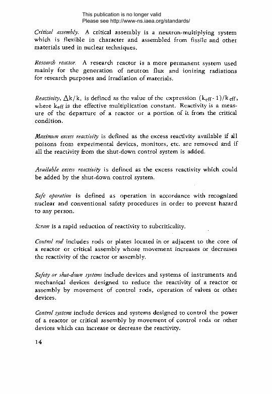
Critical assembly. A critical assembly is a neutron-multiplying system which is flexible in character and assembled from fissile and other materials used in nuclear techniques.
Research reactor. A research reactor is a more permanent system used mainly for the generation of neutron flux and ionizing radiations for research purposes and irradiation of materials.
Reactivity, Ak/k, is defined as the value of the expression (k eff- l)/ k eff, where keff is the effective multiplication constant. Reactivity is a measure of the departure of a reactor or a portion of it from the critical condition.
Maximum excess reactivity is defined as the excess reactivity available if all poisons from experimental devices, monitors, etc. are removed and if all the reactivity from the shut-down control system is added.
Available excess reactivity is defined as the excess reactivity which could be added by the shut-down control system.
Safe operation is defined as operation in accordance with recognized nuclear and conventional safety procedures in order to prevent hazard to any person.
Scram is a rapid reduction of reactivity to subcriticality.
Control rod includes rods or plates located in or adjacent to the core of a reactor or critical assembly whose movement increases or decreases the reactivity of the reactor or assembly.
Safety or shut-down systems include devices and systems of instruments and mechanical devices designed to reduce the reactivity of a reactor or assembly by movement of control rods, operation of valves or other devices.
Control systems include devices and systems designed to control the power of a reactor or critical assembly by movement of control rods or other devices which can increase or decrease the reactivity.
14
This publication is no longer valid Please see http://www-ns.iaea.org/standards/
Code o f practice is defined as the Code of Practice for the Safe Operation of Critical Assemblies and Research Reactors.
CRITICAL ASSEMBLIES
In this section some of the different practices and points of view in safety systems pertaining to critical assemblies will be discussed as far as possible and various precautions will be listed which have been developed, in most cases, through long experience. A series of design features are discussed which may be useful in the design of new facilities; in the case of existing facilities, these features may prove useful as a check-list against which those of any facility may be compared. Although a number of small nuclear excursions have occurred in critical assemblies, nearly all have been self-limiting at a level at which damage has been little or extremely moderate. The probability of a nuclear excursion in critical assemblies is certainly greater than in reactors because of the greater variety of.fuel and moderator arrangements investigated and the lack of detailed information about many of these.
SU BC RITIC A L ASSEMBLIES
In some facilities, a rule requiring the availability of one functioning safety system is applied when reactivity additions are made in which there is the possibility that the kao of the system will exceed unity. However, in many facilities, it is preferred to classify assemblies as critical if there is any possibility of exceeding criticality rather than introducing a restriction based on k « .
If the assembly is subcritical and can be kept subcritical through reasonable control of fuel and/or moderator and reflectors, many managers of facilities consider that this, as a subcritical assembly, should not require a fast safety device.
CRITICAL ASSEMBLY HAZARDS
Most of the hazards associated with critical assemblies are related to unsafe reactivity additions, involving adding too much reactivity or adding it too fast. Such uncontrolled additions may result from manual
15
This publication is no longer valid Please see http://www-ns.iaea.org/standards/

movement of fuel or poison, from mechanical instability or failure causing components to assume positions of higher reactivity worth, or from failure of monitoring instruments to provide a true indication of the multiplication so that sufficient warning was not given to reduce the rate of reactivity addition. Most accidents have happened because several simultaneous failures occurred because of design or misoperation or a combination of these.
Hazards offuel or poison movement
The hazards of reactivity addition increase considerably if reactivity is added either manually or mechanically to a system which is not subcritical to a sufficient degree, especially if the rate of addition cannot be closely controlled. In hand-loading under these conditions, care must be taken to add only a small fraction such as one-third of the reactivity which is estimated to make the assembly critical. Reactivity addition by a control system can be used to demonstrate that the amount to be manually added later is safe. While the manual addition is being performed, the control system should be in a shut-down condition (although, as noted later, sometimes a certain amount of negative reactivity is poised ready to be inserted if criticality should be inadvertently approached too closely).
Component instabilityA rather large number of accidents have occurred because com
ponents were not restrained or because of mechanical failures. Forces not anticipated in design, or damage from outside sources have caused movement of various components into positions of higher reactivity worth. This type of instability may occur with liquids as well as with solids, and consideration must be given to the effect of any such movement and to the safeguards required.
Monitoring failuresReactivity has been added excessively because the actual condi
tion of the core was not represented by the neutron monitoring instruments. Rules and checks for demonstrating that instruments are responding correctly are designed to prevent such accidents.
16
This publication is no longer valid Please see http://www-ns.iaea.org/standards/
If a critical assembly is unreflected or less than completely reflected, inadvertent criticality may occur because personnel may have to perform certain operations near the assembly, such as changing foils, and the body or hand may add considerable amounts of reactivity. If such a possibility exists, experiments should be carried out with material (such as plastics) simulating the body or part of the body such as a hand which will be near the assembly to determine whether it is safe for personnel to approach the assembly or to perform the operation.
Radiation hazards
In a critical assembly the chance of radiation exposure of personnel should not exist if precautions in reactivity addition are observed and if other safety precautions are followed. These include keeping personnel out of the assembly area or other unshielded areas during any approach to critical or, if entry is necessary, making certain that no reactivity is added while personnel are staying there. Any entry to an assembly area when the assembly is near criticality should be considered very carefully and, if it is necessary, safe rules should be developed and strictly enforced.
GENERAL SAFETY CO N SID ERA TIO N S
In critical experiments the equipment should be designed and the procedures and, most important, the attitude of the personnel should be directed towards treating each experimental assembly as an unknown mixture of fuel and moderator. Without reliance on assumptions of fuel enrichment or composition or of moderator or reflector effects the experiment should be conducted in a safe and controlled manner by adding reactivity in increments until criticality is achieved while monitoring and controlling the multiplication at all times.
Critical assemblies can be grouped under several categories. They range from those resembling reactors, often having solid fuel lattices and control rods and often being used for long series of only slightly varied experiments to get information about particular arrangements, to a generalized type used for investigating the criticality of any
Reflection hazards
17
This publication is no longer valid Please see http://www-ns.iaea.org/standards/
unknown assembly. This type of experiment is not usually concerned with such detailed investigations o f a particular lattice as would be required for reactor design. Also, in this type of experiment less information than in the first type is usually available from similar prior experiments.
In both types of critical experiments and particularly in the second, safety depends to a much greater degree on the instrumentation and safety devices and on a careful experimental approach to criticality than on calculated values which may be in error.
In cases in which an assembly is investigated intensively over a considerable number of parameter variations, it may be possible to develop very good estimates of the excess reactivity, reactivity values of safety devices, and other important safety information; however, in experiments in which considerable differences exist between assemblies, it may be almost meaningless to attempt to estimate these values in advance. Because of the variety of experimental conditions, critical assemblies do not lend themselves to routine procedures nearly as well as do research reactors, and it is necessary to place great dependence on the good judgement of the operating group. Neither safety circuits, interlocks, mechanical design, nor administrative control can possibly be sufficient to ensure the safe operation of critical assemblies or — to a somewhat lesser degree — research reactors. There can be no substitute for intelligence, alertness, discipline and training of the operating staff.
Many of the considerations pertaining to critical assemblies have obvious application to research reactors and will not be repeated in the section on research reactors.
Safety features of critical assembliesIt is probably impossible to specify all safety features of the
design so that they would apply equally to all types of critical assemblies. Those listed in this section should, however, prove useful in evaluating the design of a new or existing facility in comparison with the practices and designs used elsewhere. This comparison should enable the manager of a facility to determine those features in his facility which may need to be modified or those where stronger administrative control should be applied if this appears to be a preferable way of ensuring safety. Some features are, o f course, not applicable to a given facility.
18
This publication is no longer valid Please see http://www-ns.iaea.org/standards/

It should be borne in mind that there are a number of different design and operating philosophies, no single one of which can be defined as being the best. This can only be determined by the manager of the facility after considering the training and background of his staff, the design of his facility, and the types of experiments to be performed. Many of the practices which are sometimes set forth as standards are arbitrary, and it is very important to differentiate the fundamental safety factors from those which are merely arbitrary. These basic factors are as follows:
(a) The equipment must be able to remove reactivity more rapidly than it can be inserted by any normal operation.
(b ) The equipment must detect changes in neutron level in the core.
(c) The equipment must initiate the action of safety devices quickly and reliably when necessary to prevent the core from exceeding safety limits.
(d) The manager must establish and enforce procedures to ensure proper functioning of equipment and to prevent inadvertent or unauthorized actions which might cause unplanned criticality or overexposure of personnel to radiation. It is appropriate that the manager consider the probability of an incident or unusual occurrence and its possible consequences in determining the nature and extent of measures to be taken.
Specifications for critical assemblies
Some critical assembly designers hold the view that very complete specifications for a critical assembly should be prepared including estimates of the excess reactivity, values of the maximum rate of reactivity- addition, temperature coefficient, void coefficient, rate of heat transfer from fuel to moderator, etc. These quantities should be incorporated in the design of the core and the safety system. Actually, only the maximum safe rate of reactivity addition usually affects the design of critical assemblies since the objective is to measure assembly para-, meters even if temperature and void coefficients are positive and may therefore be inherently dangerous. The heat-transfer coefficient is important mainly for estimating the limiting value of an excursion; however, this is important primarily in considering the siting or contain
19
This publication is no longer valid Please see http://www-ns.iaea.org/standards/
ment of an assembly — matters which have already been established in most cases.
Other designers are of a somewhat different opinion, namely, that the calculation of many of these quantities is too inexact to be worth while, especially for new assemblies about which little is known. Furthermore, these designers feel that such an effort is unjustifiable in terms of cost and possible incremental safety. Accordingly, the approach is more experimental and the major emphasis is on conducting the experiment in a safe manner, without relying upon specified or calculated values of core parameters. During the course of the experiment important parameters, including those of potential safety significance, are sometimes determined and this information may then be applied to similar experiments.
The design of critical assemblies must ensure that they cannot become prompt critical. To this end it is important to ensure that any reactivity addition can be detected and that reactivity can be removed much more rapidly than it can be added by any normal operation. These detection and shut-down capabilities are probably the most important safety factors associated with critical assemblies.
Number o f shut-down systems
Many types o f safety systems are used in critical assemblies. A partial list would include moderator height, split tables with either horizontal or vertical displacement, and solid fuel "lattices with or without control rods.
It is desirable to have several different shut-down systems dissimilar enough in design to make simultaneous failure unlikely, such as control rods and moderator level; however, in some designs it is difficult to have more than one primary shut-down safety mechanism. Systems such as split-table or moderator-level assemblies in which the safety action depends upon moving the table or dropping the moderator level do not fit this criterion. Such systems generally have two ways of initiating safety action, such as two paralleled automatic valves or two separate means for moving the table. In these cases, it is necessary to make certain that the several individual, but similar, safety devices are actually independent and that a single failure cannot cause all devices to fail at the same time. At least one shut-down device having two or more independent means of initiating action of the safety device
20
This publication is no longer valid Please see http://www-ns.iaea.org/standards/

should be operative when reactivity is being increased to the point where the critical value might be exceeded. Some facilities require two independent shut-down devices.
When control rods are used, more than one is nearly always required since it is assumed that any one rod might jam or, under certain circumstances, that the rod drive might malfunction in such a way as to add its maximum reactivity. With control rods, again, there are many variations.
There are several points of view regarding the number of shutdown systems.
(a) At least two types of primary shut-down devices of different design, with one or more of each type, should be used. By having devices of different design, the chance of a common fault which causes all devices to fail simultaneously is reduced. Under this criterion, each device must be able to absorb more than the maximum credible reactivity addition.
(b) If only one type of primary shut-down device is used, the individual reliability should be increased by improved design, intensive testing, and careful operation and maintenance to the point that the failure of more than one unit out of the complement (at least two and sometimes three or more) is considered incredible. Great pains must be taken to ensure that no single failure can cause more than one of the units to fail to operate. No single device should be capable of making the assembly critical if the others are fully inserted.
Shut-down devices — time of operation
Shut-down devices must, of course, operate quickly enough to allow safety systems to become effective. One approach is to specify that the time of operation, including detection and operating time before the safety devices are fully effective, should be less than 50% of the reactor period resulting when the maximum permissible single addition of reactivity is made above the critical value. However, this specification is difficult to administer in critical assemblies in which the values are not known.
As a practical matter it is desirable to make shut-down devices and their initiating instrumentation operate as quickly as possible within reasonable limits. Nearly all devices can be made to begin their initial movement within a few tens of milliseconds and to complete their
21
This publication is no longer valid Please see http://www-ns.iaea.org/standards/

action within less than one second. Gravity-driven control rods, for example, will generally complete a stroke of two feet within 400—600 ms.
Some assemblies have secondary shut-down devices in which the time of operation is longer than that of the primary device. This may give added reliability from the point of view of having a separate device of different design; however, this must be balanced against the desirability of adding another primary device which operates more rapidly, rather than relying upon the slower secondary device.
R EA C TIV ITY CO N SID ERA TIO N S
Excess reactivity
The value of excess reactivity to be used in setting the worth of the safety or shut-down system has several interpretations. In one, the maximum excess reactivity is used and includes all reactivity which might be held down by experimental equipment, monitors, capsules, etc., as well as that compensated for by the shut-down or safety system. An alternative interpretation considers only that amount of reactivity which is actually available from the movement of the safety and control devices in determining the necessary reactivity worth of the safety system. Under this second method the worth of the shut-down system is usually made considerably larger (such as a factor of two) than the available excess reactivity. Under the first method, a smaller margin is generally used over the maximum excess reactivity (such as a factor of 1.25 or 1 .5); however, depending on the worth of experimental rigs and other poisons, the available excess reactivity may be equal to the maximum excess reactivity or it may be much smaller. If equal, the ratio of shut-down margin to the available excess reactivity may be as low as 1.25— 1.5, whereas, if the available excess reactivity is much smaller than the maximum excess reactivity, the shut-down margin becomes much larger. With the second method, adequate procedural and mechanical precautions are taken to prevent inadvertent removal or insertion of any objects which might increase reactivity, and it is assumed that the shut-down margin, being large, could compensate for any accident affecting one or two experimental rigs, monitors, etc.
Such considerations become important primarily in systems having control-safety. rods which must have worths exceeding the
22
This publication is no longer valid Please see http://www-ns.iaea.org/standards/
maximum or available excess reactivity by some prescribed margin. With moderator-height or split-table assemblies, it is usually possible to make the system subcritical by much larger shut-down margins.
Reactivity addition from equipment failures
It is worth while to expend a great deal of effort in design to minimize the possibility of electrical or other equipment failures, which might cause the unintentional addition of reactivity. However, it should be clear that such failures have occurred in the past in spite of the best efforts of operators and designers. Operators of critical assemblies should be aware o f the possibility of failures and remain alert to the hazards which might ensue in spite of the use of safety features in the design. Electric-motor-driven safety and control devices should be carefully examined for mechanical failures which cause the motors to fail to reverse, or for failures other than mechanical which cause the motors to continue withdrawing negative or inserting positive reactivity.
Reactivity worth o f safety systemsThe basic requirement of a safety system is that it detect un
acceptable additions of reactivity and remove reactivity much more rapidly than can be added by normal means. The shut-down worth of the safety system is usually ample in the case of split-table or moderator-level assemblies which can be made subcritical by a very large amount. With control-rod safety devices, however, there is sometimes a question of how to evaluate the amount of excess reactivity and the way it should be controlled by the safety system. A common approach to this question is to assume that, should at least one control rod be withdrawn from the reactor completely through some malfunction in the driving or instrument system, the assembly would still be subcritical with the other rods inserted. Coupled with this criterion is one that each safety system be composed of at least two separate shut-down systems. Each shut-down system, representing one or more control rods, should be capable of absorbing 125% of the maximum reactivity release. In this case, maximum reactivity release is presumably the reactivity which might be available if all absorbers in the core were removed and all normal positive reactivity were added.
23
This publication is no longer valid Please see http://www-ns.iaea.org/standards/
A somewhat different approach to this problem is one in which the criterion that no single control rod should be capable of making the assembly critical is coupled with one that the available reactivity, that is, the reactivity actually held down by the control rods but not including any reactivity absorbed in the experiments or other devices, should not represent more than one-half the total value of the safety system. Experimental rigs and objects which might be withdrawn or added in ways to increase reactivity should also be limited to safe values so that no single one being moved could cause a serious accident. One such rule is that no single, movable experimental rig should be worth more than 0.5% Ak/k or other appropriate value less than the delayed neutron fraction. This rule limits reactivity which might be added from an inadvertent movement of a sample or experimental rig while the reactor is critical or supercritical. It also provides a constant ratio of the shut-down margin to the available excess reactivity and assumes that administrative control can be used to prevent inadvertent additions of reactivity beyond the capability of the safety system.
Reactivity addition — temperature coefficient
Since a positive temperature coefficient could increase the severity of a nuclear excursion, it is desirable that all assemblies have a negative temperature coefficient; however, this is often not a practical solution as it is sometimes necessary to proceed with the investigation of assemblies even if they should have positive temperature coefficients. When much is known about a certain type of assembly, it may be possible to improve the effective temperature coefficient through appropriate design modifications; however, in many assemblies this is not possible and the staff should remain alert for a positive temperature coefficient and exercise due care in proceeding with the experiment.
Reactivity addition — void coefficient
Void effects should be determined where these may affect, safety and, of course, any operation which creates or removes a void should be carefully studied from the reactivity standpoint, since the void coefficient may be either positive or negative and may also be dependent on its location within the assembly.
24
This publication is no longer valid Please see http://www-ns.iaea.org/standards/

Accidents which should always be considered are those which follow from reactivity increases due to some sort of mechanical failure, accidental fuel movement, flooding of void regions, etc. All components and materials whose displacement could result in a change of reactivity greater than about half the delayed neutron fraction should be securely restrained by mechanical devices to prevent their being displaced. This requires careful attention to structural factors, such as stresses and deflection, design of fasteners, methods of attachment of devices such as neutron detectors to the assembly, and to the physical and chemical stability of all core components. Fluids, voids, plastics, and brittle materials may require careful consideration.
In most solid fuel cores it is possible to lock or load the fuel in such a way that no subsequent accidental movement can take place which might cause a change in reactivity. If this cannot be done, as, for example, in a core where the fuel is suspended and free to move from side to side, the maximum reactivity change which might occur should be examined to make certain that a dangerous situation cannot arise.
Cases have occurred in which a fuel element has been raised by the motion of an adjacent control rod. Although no serious accident has occurred through such an element falling back into the core, most designs now provide for mechanical grids to hold the fuel in place so that it cannot be affected by the movement of a control rod.
Cavities which can be filled with water or drained may have considerable reactivity worth. Such situations often exist in the beam holes of research reactors. Furthermore, any such Cavity, if located near the neutron-detecting chambers, may cause large variations in the number of neutrons detected by the chambers.
Incidents have occurred from such causes and should warn operators of the need for good structural stability and for administrative control of any change. It is difficult to anticipate every possible hazard of this type, but personnel should be continually alert for the possibility of trouble from such matters.
One of the chief reasons for restrictions on personnel access to critical assembly areas is to prevent the inadvertent or unauthorized movement of components in such ways as to increase the reactivity or to otherwise increase the hazard.
Reactivity addition — displacement of core components
25
This publication is no longer valid Please see http://www-ns.iaea.org/standards/

The way in which reactivity is added varies, of course, with the design of the critical assembly. When moderator height is the means of reactivity addition, the design generally permits the moderator to be raised slowly but more or less continuously. In split-table assemblies the movable table may be brought towards the other half of the assembly slowly but again continuously. The possibility of continuous addition of reactivity again holds when addition is by the removal of control rods. In every case the addition should be controlled by the response of the neutron instruments and limited by the safety system. Instead of reactivity being added continuously, it may be (and usually is) added in discrete amounts followed by a period of time during which the effect of the addition is observed. The additions must become progressively smaller as criticality is approached.
Even more care than usual should, of course, be taken when making an initial approach to criticality with a new assembly. Under these conditions, reactivity addition should not be made unless the effects of any preceding addition have been observed and understood. When the assembly is shut down in order to load additional fuel, as in the case o f a lattice experiment using control rods, the reactivity worth of fuel added in each increment should be much less than the reactivity worth of the control rods.
In experiments with assemblies containing variable amounts of fuel where the purpose is to determine the amount of fuel or other reactivity-producing factors which will make the assembly critical, it is customary to begin with a much smaller fuel loading than is expected to be critical and to conduct a series of approach-to-critical experiments with fuel being added after each until the assembly is critical. In this procedure reactivity is added during the approach to critical in different ways according to the design of the assembly. The addition is often by withdrawal of control rods, although other types of reactivity addition could be used, such as moderator height, table displacement, etc.
With moderator-height or split-table assemblies, when the core configuration is fixed and the purpose is to determine whether a configuration is critical or not, the reactivity addition during an approach to critical will usually be done by raising the moderator height or moving the table while watching the effect on the neutron level. After each incremental addition of reactivity, movement should be stopped to allow transients to decay.
Reactivity addition rate during approach to critical
26
This publication is no longer valid Please see http://www-ns.iaea.org/standards/

Critical assemblies about which little is known in advance of experiments, such as assemblies of fuel and moderator which have not been operated previously, cannot be calculated with enough certainty to fix reactivity addition rates. The experimenter should always consider the fundamental question of whether reactivity additions can be detected promptly and whether reactivity can be removed at a faster rate than it can be added by any normal operation, at the same time taking into account any credible malfunction of equipment. The experiment should be planned and carried out carefully enough for criticality to be reached safely even though the experimenter may not know many of the safety parameters.
With assemblies about which much is known, such as those whose purpose is to explore a specific reactor design, it is often possible to estimate the reactivity addition rate in advance of the experiment. For this type of assembly the rate used varies with different design and safety philosophies. Although the generally accepted safe rate of 0.02% Ak/k per second is sometimes used, a more appropriate rate may be chosen to correspond with the results of a safety analysis of a particular system in which consideration is given to the detection level, the trip level, the response time of the safety system, and the time required for the safety system to become fully effective. Values as high as 0.1% Ak/k per second are used in reactors which are designed for such rates.
Reactivity addition rate — speed of devicesCritical assembly reactivity addition devices, such as split-table
movement, moderator-height control, and control rods, are sometimes moved at a higher rate during the early part of the approach to critical than can be sustained safely as criticality is neared.
The protection scheme should include means of detecting the increase in neutron multiplication and limiting the rate of reactivity addition accordingly. If this is achieved by instrument interlocks, some designers feel that the interlocks should meet all the criteria for reliability and performance required of the rest of the safety system.
Other designers prefer to consider such devices as part of the control system which is kept entirely separate from the safety system. The safety system is designed to have the highest reliability and to handle safely any excursion caused by a failure of the control system.
27
This publication is no longer valid Please see http://www-ns.iaea.org/standards/
If reactivity is added manually by the operator, the rate of addition should be guided by the response of the neutron-detecting instruments.
Procedure for adding fuel in a rod-controlled system
I f a control-rod system is used, there are a number of variations in the procedure for adding fuel. One practice requires that a 'cocked rod' procedure be used during any fuel addition in which there is a possibility of the assembly becoming critical. A different practice is to have all rods inserted when the addition is made but to require that the amount added be small in relation to the shut-down margin. A third variation sometimes used is to dump the moderator before any fuel addition, making the assembly considerably subcritical. Following this the shut-down rods are cocked before raising the moderator level, and the final criticality is achieved ( if estimates are correct) by the movement of the shim rods.
Another rule for fuel addition frequently used in an assembly having control rods is to make estimates of the worth of shut-down and control devices and to limit the reactivity added in each increment to less than 50% of the worth of the control device. With safety-shim rod systems, this would ensure that criticality is reached while withdrawing the shim rods. The rule as stated is not directly applicable to a control-rod system in which all rods have safety and shim features and in which all rods are withdrawn together. As noted in the section on control rods, however, the fuel added in each increment should be only a small fraction of the shut-down margin so that criticality will be reached when the rod complement is fairly well withdrawn.
Reactivity addition — positioning and indication o f devices
In order for the operator to control exactly the location of the device providing the reactivity addition, such as the control rods or moderator height, the control mechanism should incorporate features to make possible the regulation of the rod position from the control console and should provide an accurate reading of the rod position. The mechanism should not only position the addition-device accurately, but the positioning should be repeatable. The device must also be capable of remaining fixed in any desired position so that forces other than the drive mechanism acting upon the device cannot move i t This
28
This publication is no longer valid Please see http://www-ns.iaea.org/standards/

may require that the motors used to drive the mechanism have brakes or gear trains to stop the drive within very short distances after the power is turned off or it may require fast acting valves to control the flow of moderator, etc.
Failure of a position indication in an assembly with control rods might result in one rod being fully inserted, with other rods being moved more than usual to compensate. This would bring about a confusing indication in the control room since neutron detectors might respond quite differently, depending upon their position relative to that of the control rods. In the case of a reactor, such a situation might result in the power density being abnormally high in part of the core.
Reactivity addition — inverse multiplication curve
An inverse multiplication (or flux counting rate) graph may be a useful guide for the addition of reactivity and is sometimes used in approach-to-criticality operations to predict the point at which criticality will be reached. This is especially suited for lattice-type cores to which fuel is added in increments in the presence of moderator and reflector and where the assembly is shut down by control rods between additions of fuel. The inverse flux curve is then a useful guide in determining the amount of fuel to be added. Some facilities hold to a rule of adding a maximum of about one-third of the estimated amount of fuel needed for criticality. A further limitation often adopted when loading fuel or other sources of reactivity in moderated assemblies’ or reactors having control devices is that the amount added should be less than half the worth of the control devices. In control-rod systems having shut-down, shim, and regulating rods this would represent half the worth of the shim and regulating rods; in a rod system where all rods have safety and shim functions, the amount added at one time should be a small fraction of the whole rod complement.
Critical experiments with a fixed lattice to which reactivity is added by moderator height, split table or vertical displacement are often done without the use of an inverse flux curve; instead, reactivity is added in small increments depending on the response of the neutron detectors with , a pause after each addition until the transient effects have decayed.
29
This publication is no longer valid Please see http://www-ns.iaea.org/standards/
For the investigation of a fixed-quantity core assembly, reactivity would normally be added by raising moderator height, moving split tables, etc.; the purpose is generally to determine whether a particular configuration is critical, subcritical, or supercritical. With this type of experiment, there is generally no question of adding fuel until after the particular approach to critical has been completed, at which time the assembly would be completely shut down before any fuel changes are made. If, however, a variable-size assembly is to be investigated, the question arises as to how much fuel should be added for the first subcritical core before performing an approach to critical. In this type of assembly solid fuel elements are often used and the first assembly should be chosen so as to be subcritical — usually about one third of the predicted critical mass. I f no information is available on the criticality aspects of a particular type of fuel, it is necessary to proceed cautiously until information is gained to ensure that the first core assembled does not have too much reactivity. When sufficient experience is available, it may be possible to perform calculations to give the estimated critical mass sufficiently accurately to permit the start of critical experiments with about one-third of the predicted critical mass.
Staff responsibility for reactivity addition
In performing critical experiments, the staff who are authorized to decide on each reactivity addition should be designated by the manager. Some facilities have a rule that two senior staff members, such as the manager and his chief assistant, should agree before any reactivity addition. In any case, those authorized to make such a decision should agree and, in fact, it is a generally accepted rule that if anyone expresses doubt about a particular action the operation should be suspended until the doubt is resolved.
N EU TRO N SOURCE
Use of neutron source
The use of a neutron source is always required during an approach to critical or on any start-up of a critical assembly or reactor
Fuel addition in variable-size assembly
30
This publication is no longer valid Please see http://www-ns.iaea.org/standards/
or when safety rods are at a suspended position in the cocked-rod procedure unless there are sufficient neutrons from spontaneous fission or from neutron generation which may occur with certain materials, such as those which give sufficient (a ,n ) or (y, n) reactions to provide an adequate number of neutrons. The strength of the neutron source should be sufficient to provide an indication on the neutron-detection instrumentation before a significant quantity of fissionable materials is added to the assembly. The source and detector should be positioned so that most of the neutrons reaching the detector after fissionable materials are added come from the core rather than directly from the source. Special experiments in which reactivity effects are known and limited may be performed without a neutron source.
When the neutron source is removable, it is common practice to remove and reinsert the source before starting the approach to criticality to make sure that the movement is indicated by response of the neutron detectors. Alternately, it may be preferable to move the detectors.
Since it may be necessary to remove the neutron source from a critical assembly after it is critical, the reactivity effect should be considered. For example, the neutron source is often removed when criticality is reached and this may have approximately the same effect as removal of a void. The reactivity effect of this should be determined by some safe procedure.
Source position before start-up
The neutron source, if one is required, should be within or adjacent to the core in its designated position and neutrons should be indicated by detectors.
The position of the source relative to the position of the detectors is very important since an improper arrangement may cause neutrons from the source, rather than neutrons multiplied by the core, to be detected by the detectors. For this reason it is sometimes desirable to have the source inside the core and the detectors outside. Until a particular arrangement has been demonstrated to give the proper response, reactivity should be added very carefully.
31
This publication is no longer valid Please see http://www-ns.iaea.org/standards/

Neutron source interlocks
Mechanical and/or instrument interlocks are sometimes provided to ensure the presence of the neutron source by means of a minimum value of counting rate or neutron flux level before reactivity addition is permitted. However, there is not uniform agreement on this point, and some facilities take the position that with a well-trained staff it is safer to rely upon administrative control rather than upon interlocks which may be intentionally or inadvertently deactivated. Also, a mechanical or instrument interlock is sometimes used to ensure that the source is in a safe, shielded position when the assembly area is entered by personnel. Here again, however, some managers feel that if personnel are always required to monitor radiation they are less likely to be endangered should the interlock fail to operate.
C O M M ISSION IN G AND OPERATION
Pre-commissioning approval for a critical assembly or research reactor
Approval by the regulatory body is required .of the safety report, the limits and conditions, commissioning tests and results, operating instructions and program of periodic testing, as provided in Sections2, 3, 5, 6, and 10 of the Code of Practice. Since these must be prepared in advance o f actual operation and since changes in the limits and conditions and operating instructions require regulatory body approval or surveillance, the manager should* prepare these with great care. I f possible, he should compare how they have been prepared and changed at other sites. In addition, the Code of Practice requires that maintenance and emergency procedures should be prepared.
Pre-commissioning tests
Tests prior to initial start-up of a critical assembly or reactor should be planned and compiled and the program and results should be submitted to the regulatory body as provided in Section 5 of the Code of Practice. The tests should be designed to ensure that all mechanical, electrical and electronic equipment is in working order. Although every aspect and function of every system cannot usually be checked before criticality is achieved, many systems can be operated
32
This publication is no longer valid Please see http://www-ns.iaea.org/standards/

to give useful functional tests. It is advisable to put each system into operation as soon as it is completed and to continue operation of the individual systems as long as possible. During these tests, any malfunction or unusual changes should be noted and any remedies required should be performed. During this time, also, the procedures for system operation, start-up, and any other special operations, together with the necessary tools may be developed.
Approach to critical with a new core in a critical assembly
The safety approval of new experiments proposed for a critical assembly facility, which itself has the necessary approvals, is one of the first steps to be undertaken in preparation for any new experiment.
An experiment procedure should be prepared with a section which specifically evaluates the effect of the experiment on each of the limits and conditions which were approved for the critical assembly under Section 3.1 of the Code of Practice.
Approach- to-critical precautions
The neutron detectors should respond to removal and insertion of the source ( if a removable source is used it may be removed and reinserted to make certain that the neutron-detecting instruments are detecting neutrons), and the safety or control instrumentation channels should be on scale, indicating that they detect neutrons. Additions of reactivity should be indicated by the neutron-level instrumentation (power instruments should show an increased reading and period meters should also respond). I f the addition of reactivity is not indicated by a change in neutron level, the situation should be carefully evaluated before proceeding. A possible hazard of this type of situation is that through some malfunction the instruments are not indicating the neutron level properly or the neutrons reaching the sensors come mostly from the neutron source instead of from the core, indicating that the source or detectors are positioned improperly. The hazard of continued reactivity addition lies in the possibility of suddenly exceeding criticality without the neutron-level safety devices giving adequate response until some undesirably high power is reached.
If any anomalous behaviour occurs in the neutron-level instrumentation, further addition should be stopped until this is understood.
33
This publication is no longer valid Please see http://www-ns.iaea.org/standards/

During any change in the instrumentation, such as scale changing, or change in equipment, such as changing the position of a detector, no reactivity should be added.
If control rods are used as the means of adding reactivity and special limitations exist in their rate of movement, these limitations should be carefully observed, especially in the last part of their stroke near criticality. Similar speed limitations, usually a design feature automatically activated, exist with split-table, vertical-movement, or moderator-height assemblies.
Shut-down
At the conclusion of a critical experiment, it is generally desirable to shut down the system by removing reactivity by draining the moderator, or separating the parts of the assembly, or inserting control rods, or whatever combination of these is available. The procedures for safe shut-down should be specified. If fuel must be unloaded the procedure should be specified if there is a possibility of increasing reactivity from the operation by increasing the lattice pitch or by some other mechanism.
PRO CED U RES FO R CRITICAL EXPERIM ENTS
- Critical experiment procedures or core certificates are widely used, where appropriate, to ensure that all personnel connected with the critical assembly >knows at any time the state of the assembly and the operations which may be performed. Such a procedure is used to ensure that the manager approves all such operations and that the required safety review is performed; it also prevents unauthorized changes which, may not have been properly reviewed.
Whenever a new experiment is to be performed or an important design change has been made, the manager should determine whether adequate procedures have been prepared and whether the staff has been adequately trained in the operation of the equipment and the associated procedures. Written procedures, if properly used, can be of material assistance in ensuring safe operation. Procedures should be written for each operation and should apply to whomever performs the operation; and, in general, they should not specify that particular staff members perform certain operations, although this may be done
3 4
This publication is no longer valid Please see http://www-ns.iaea.org/standards/

for very important operations. In critical experiment facilities, completely detailed general procedures are difficult to prepare, since critical experiments are often designed to measure unknowns and may produce unexpected developments. The procedures should comply with the approved limits and conditions as provided in Section 6.1 of the Code of Practice, and they should be made available to the regulatory body. In cases where critical assemblies are operated for long periods of time with the same core or similar cores, especially where control-rod systems are used, the procedures may be of the more detailed type used for research reactors.
Format for critical experimentA suggested critical experiment procedure would include:(a) The purpose and general description of the experiment.(b ) A core description with a complete pattern of fuel,
moderator and reflector.( c ) Safety and control system description. The tests required
to give confidence in the safety action prior to and during the experiment should be specified and the safety system settings should be shown.
(d) Description of the devices for adding reactivity. The point of criticality and the maximum reactivity addition rate should be estimated if enough is known about the assembly to make reasonably accurate estimates. For generalized critical experiments these values may not be known; however, for critical experiments on reactor lattices in which a large number of experiments are performed on the same or similar cores there may be enough information available to give confidence in such estimates. After the experiment, the measured values should be noted for comparison with the estimates and for improvement of future estimates.
(e) The procedures to be used during the experiment. These should include procedures for fuel loading, for step-by-step operations, and for dismantling or unloading.
( f ) Any special precautions or emergency procedures.(g) An evaluation of the effect of the experiment upon the
limits and conditions which govern the critical assembly facility. Experiments which cause any of these to be exceeded require further approval, as noted in Section 4.1 of the Code of Practice. If changes
35
This publication is no longer valid Please see http://www-ns.iaea.org/standards/

in the limits and conditions are required, the reasons should be noted and the proper approvals should be obtained.
(It should be noted that several of the items above including(c) and (d) should be mostly covered in the system description which is normally written to accompany a safety report for the facility. It should only be necessary to refer to the safety report to provide most of the description.)
Approval o f critical experiments
In fixing the level of approval required for a critical experiment, it must be determined how the experiment affects the limits and conditions approved for the facility by the regulatory body and how it affects any limits imposed by the safety committee. Three different levels of approval are likely to occur in a typical situation.
1. Regulatory body approval
If the experiment may cause the approved limits and conditions to be exceeded or have a bearing on the established safety principles or if it will entail hazards different in nature, greater in magnitude or more likely to occur than those previously associated with the facility, then regulatory body approval (as noted in Section 4.1 of the Code of Practice) would be required in advance of the experiment. In practice the original limits and conditions might be sufficiently broad to permit most experiments to be done within this framework. If a review is required, safety documents should be submitted, usually through the safety committee (see Section 4.1 of the Code of Practice).
2. Safety committee approval
If the experiment is within the approved limits and conditions, it still may require safety committee approval depending upon the scope for the approval of experiments which has been accorded the manager. If safety committee approval is required, the documentation should be agreed upon between the manager and the committee. In- many cases an experiment procedure together with an analysis of the hazards and their consequences should be sufficient at least for an initial review.
36
This publication is no longer valid Please see http://www-ns.iaea.org/standards/

If the experiment is within the limits set by the regulatory body and the safety committee, the manager may approve it. Since the manager is the person having direct knowledge of the experiment and its possible exception to Section 4.1 of the Code of Practice as well as any exception to limits imposed by the safety committee, he must decide whether an experiment should be submitted for higher review. In practice, the manager usually refers an experiment to the safety committee if he has any doubt about its acceptability, and the safety committee determines whether it should be referred to the regulatory body.
Consideration should also be given to the approval of repetitive experiments which differ only slightly from ones previously approved, since the problems of review may be simplified. To avoid misunderstandings it is advisable for the safety committee to agree on the criteria under which the manager can approve such experiments.
Equipment and procedural checksBy the time the facility is ready for operation, detailed check-lists
should have been prepared which prescribe the tests of the essential equipment, especially safety systems. The check-lists should specify the maximum and minimum acceptable results where applicable; any result outside these limits should be cause to have the system repaired. After being completed, the check-lists should be signed by the person in charge of the start-up. In general, these should ensure that the core is prepared according to approved instructions, that any experimental facilities are in a safe condition for start-up, that all maintenance has been completed and properly checked, that all auxiliary systems are in working order and ready for start-up, and that all safety systems are in working order. This will generally include a check of the functioning of the safety devices and may also include the time for the devices to operate.
A check-list may contain, for example, detailed checks as follows:Log-book for condition of equipmentMaintenance checks to ensure that all maintenance of essential
equipment is complete and that tests have demonstrated the operability of the equipment
3. Approval by manager
37
This publication is no longer valid Please see http://www-ns.iaea.org/standards/

Safety device checksSpecial instructionsVariable-range instruments in the correct rangeInterlock block or cut-out checksInstrument functional checksCritical experiment procedure approved, if required.
The following checks are often performed at regular but less frequent-intervals:
Radiological instrument checksCommunication equipment checksCalibration checksEmergency and accident equipment and procedural checks.
Final safety approval and checks before approach to criticalThe manager must ensure that the required safety approvals are
obtained and that the preliminary checks are completed before permission is given for an approach to critical with a new core. Subsequent start-ups may require no further approval but the conditions requiring further safety approval should be specified; the checks and safety precautions to be followed before each start-up should, likewise, be clearly designated. When the check-lists have been completed to ensure that all systems are calibrated and operating and the necessary approvals have been received (including an approval of the critical procedure), the assembly of the core may begin.
The manager is responsible for making certain that one responsible person is designated to be in charge of any start-up. This person should supervise all further steps during start-up, enforce all safety precautions, and ensure that personnel perform their designated functions. For example, if procedures require that a certain number of people participate in certain operations, such as in loading fuel when it is sometimes required that two persons be present, these requirements should be enforced. It is also a good practice to make certain that the control room does not become so crowded that the person in charge of the start-up may have his attention distracted.
Familiarizing the staff with proceduresMembers of the operating team must be given adequate time
before an experiment is carried out to study the instructions and pro
38
This publication is no longer valid Please see http://www-ns.iaea.org/standards/

cedures thoroughly, and the necessary members of the staff should be assigned specific tasks. They should be examined in these procedures before working on the assembly and,, in addition, re-examined at regular intervals and after long absences from the assembly. This examination, which may be carried out by the manager, should cover, in addition to the normal operating procedures, the procedures necessary in an incident or emergency. At many facilities these examinations are written and filed as a record of the adequacy of training.
RESEARCH REACTORS ’
GENERAL SAFETY C O N SID ERA TIO N S
One of the major safety differences between research reactors and critical assemblies is, of course, the considerably larger inventory of fission products carried in research reactors which have operated long enough to achieve some burn-up of their fuel. Research reactors are, however, usually more stable ,in their design and in their core arrangements than critical assemblies. They are, therefore, more amenable to the development of routine procedures and specialized safety devices.
The nuclear excursions which have occurred bear out the significance of this difference. Most excursions have occurred in critical assemblies; however, the few reactor incidents which have occurred have, on the average, caused more damage than critical assembly incidents in which there has usually been little, if any, damage to equipment, although radiation injury o f personnel has occurred in a few cases.
Although the safety precautions and the limits and conditions of operation can be specified much m6re readily for a research reactor than for a critical assembly where different assemblies may be tested frequently, the relative stability of a research reactor should not cause the staff to become complacent. The equipment, the procedures, and the training and qualification of the personnel must be under constant review; all are important safety factors. .
Many safety principles apply to both critical assemblies and research reactors; however,: it is proposed to emphasize here those features and operations having special significance to research reactors.
39
This publication is no longer valid Please see http://www-ns.iaea.org/standards/

RESEARCH REACTOR HAZARDS
Safety problems at research reactors more often involve radioactive contamination resulting from the higher neutron and heat fluxes than those related to critical assemblies. On the other hand, the cores of research reactors are usually more or less fixed so the hazards of inadvertent criticality are easier to control. A number of different types of accident have occurred in research reactors but the majority fall into only a few categories. In designing protection systems and in formulating procedures, the safety procedures and the safety equipment should be made to supplement each other so that any probable accident has several defences, any one of which would prevent the accident from actually occurring. The manager should always be vigilant for potential accidents which do not have several defences and should take appropriate measures to improve such defences. Any probable accident with only one defence may have a rather high probability of occurring, and this is often higher than an acceptable risk, whereas the probability can be greatly reduced by providing a second defence. Most accidents which have occurred have resulted from more than one (and often four or five) malfunctions of equipment, improper procedures, and personnel errors.
Fuel melting incidents
Most fuel melting incidents have occurred when some extraneous object, such as a plastic sheet or shoe covers or a gasket, has restricted coolant flow in one or more fuel elements. This type of accident is not so likely to occur in a low-power research reactor in which the heat fluxes are low; a more likely accident is the melting of an uncooled irradiation sample containing too much fissile or other heat- producing material. These incidents often result in considerable spread of contamination, especially of fission gases.
Maintenance-related incidents
Mistakes made during maintenance operations have Occurred fairly frequently and have made necessary the adoption of rules for ensuring that the core is subcritical with any single rod removed if the others are inserted, for checking safety systems before start-up, for forbidding
40
This publication is no longer valid Please see http://www-ns.iaea.org/standards/

maintenance on safety-related systems during operation, and for controlling maintenance by close surveillance, formal work permits, and extensive checks before the operation of any equipment on which maintenance has been performed.
Contamination incidentsRadioactive contamination may be spread by any process which
allows radioactive gases or particles to escape. Such accidental releases have usually occurred because of improper encapsulation of materials to be irradiated, pressure build-up, or improper design of the capsule. Materials properties are a very important consideration and, until the personnel involved have gained experience, it is best to proceed cautiously. Materials which appear to be resistant to corrosion on the basis of published properties may release enough radioactivity from their surfaces to cause contamination problems. Contamination which escapes the reactor system (including the coolant system) is most serious since this may require an evacuation of the building or, at best, many restrictions including the use of protective clothing, traffic control, frequent monitoring, and clean-up. Gases are the most likely materials to escape; but, on the other hand, fission gases have relatively short half-lives and are quickly dissipated. Radioactive contamination dissolved in water systems can be removed easily by clean-up systems except for a small fraction which deposits on surfaces of the coolant and reactor systems and which then requires contamination control during maintenance. Particulate contamination of water systems can be difficult to remove since particles may settle on surfaces instead of being drawn into the clean-up system from which they can be filtered out. A second type of contamination incident is frequently caused by handling in air objects carrying many radioactive particles. The particles often become airborne and are spread over the reactor building. Careful surveillance is necessary to detect this situation before the contamination is widely spread.
Instrumentation-related incidents
Incidents related to instrumentation generally result from one of two causes. Either the instrumentation is faulty and does not perform its function, or the instrumentation gives indication of some abnormal
4 1
This publication is no longer valid Please see http://www-ns.iaea.org/standards/
condition and is misinterpreted. The possibility of faulty instrumentation necessitates such precautions as checking the positioning of neutron sources and detectors, checks to ensure that reactivity additions are properly indicated by the instrumentation, and testing the safety system frequently. Neutron detectors may have become saturated or insensitive to further increases of power; this is a reason why start-ups, especially initial start-ups and those after maintenance has been performed, should be done in careful steps with cross-checking between the neutron level (power) and an independent parameter. Accidents such as the filling of voids with water can cause anomalous instrument response. The second type of accident, which is due to misinterpretation of instrument signals, can only be prevented by vigilance on the part of the operating staff. Similarly, unreliable safety or control instrumentation may be a safety hazard, since frequent instrument trouble is liable to cause the operator to disbelieve an instrument signal when it indicates a truly abnormal condition.
Reactivity addition incidents
Although few serious incidents have occurred in low-power research reactors, there is always the possibility of an incident occurring from fuel handling, from movement of high-reactivity-worth components, or from a malfunction of the reactivity-addition system. As mentioned above, the limitation preventing criticality being achieved with any one control rod withdrawn (if others are inserted) is intended to preclude a reactivity accident if one rod should be withdrawn manually or by a malfunction of the rod-withdrawal mechanism. The administrative controls recommended in performing work in the core provide a line of defence for such accidents. The possibility of a reactivity accident from a movement of fuel, moderator, or reflector is the reason for limiting such movement by good mechanical design and maintenance, for loading fuel in such a manner that high-worth additions are avoided, and for limiting the reactivity worth, whenever possible, of components, experimental rigs, and voids which might add reactivity. An adequate shut-down margin is one of the most important safeguards against reactivity incidents, and the need for guaranteeing an adequate shutdown margin is the reason for many of the recommendations regarding the worth o f the shut-down system in relation to the available and maximum excess reactivity. Limiting the reactivity addition rate is
42
This publication is no longer valid Please see http://www-ns.iaea.org/standards/

another very important safeguard against accidents, and the precautions on adding reactivity, when an assembly is near criticality, by any means other than the designed reactivity addition devices are for this purpose.
Radiation incidentsSerious radiation incidents have not occurred very frequently in
research reactors but they are potentially very serious since they may involve the exposure of personnel. All of the safety precautions are basically aimed at preventing the release of radioactive contamination or avoiding high-radiation fields which might endanger personnel. Shielding requirements, control o f access to zones of high radiation, and precautions aimed at preventing reactivity excursions all provide related lines of defence. Building containment is another line of defence to prevent radioactive materials released inside a building from escaping and causing a much more serious incident.
Strong administrative control o f work in radiation fields, good records of the exposure accumulated by each person, and a limitation on the maximum radiation field to be entered without special permission are precautions which, when taken together, can successfully prevent exposures beyond a safe limit. The use of adequate radiological instrumentation installed at various points in the building together with rules which require personnel to monitor for themselves are precautions aimed at preventing personnel from entering radiation fields without being aware of it.
Experiment incidentsAlthough experiment incidents are likely to fall in one of the
above-mentioned categories, it is worth while to mention some of the reasons why they are apt to occur. Experiment incidents are usually caused by improper design, often due to unfamiliarity of the designers with reactor and radioactivity problems, or due to lack of communication between different groups involved in the design. These are some of the reasons for the safety review of experiments and for careful attention to the organization and co-operation of the various groups.
43
This publication is no longer valid Please see http://www-ns.iaea.org/standards/
REACTIVITY ADDITIONS
Most of the reactivity addition considerations are covered under 'Critical Assemblies'. However, a number of special problems apply to research reactors.
Limitation o f reactivity addition by design
It is sometimes attempted to make a reactivity accident impossible by design features which limit the amount of reactivity which can be added at one time. It is almost impossible to eliminate all hazards by design; even if this were attempted, a disadvantage would ensue, in that the flexibility and utility of the reactor would be severely limited. As in most other safety matters, there is no substitute for an alert, well-trained staff and adequate administrative control. Except through severe limitations in the fuel supply, it is difficult to completely prevent, by design features, situations in which a reactivity accident might occur in a research reactor through the addition of fuel. For example, a core could be loaded leaving a central position vacant which might, under some circumstances, have enough reactivity worth on the addition of a fuel element to cause- a severe accident. In order to entirely eliminate such a possibility, it might be desirable to make each fuel assembly worth very small; however, this would be difficult and expensive since the fuel o f most research reactors is already designed. Administrative control should require that, when reactor cores are being loaded, the fuel should be loaded compactly without leaving vacant positions which have high reactivity worths. I f such a position is needed for an experiment, some physical structure should be provided to prevent the inadvertent addition of a fuel element. The reactivity worth of such experimental facilities should always be considered in relation to the shut-down margin and strict administrative controls should be used.
Reactivity variations caused by fuel or control-rod vibrationCoolant flow in reactors will sometimes cause fuel or control
rods to vibrate with consequent changes of reactivity. This is undesirable because the safety and control instruments often indicate rather large variations in power and period which may mask other more
44
This publication is no longer valid Please see http://www-ns.iaea.org/standards/
serious irregularities. It is generally possible to devise mechanical guides or other means of restricting the lateral movement of control rods and to provide grid plates with small clearances and spacing tabs at the upper end of fuel elements to reduce vibration.
Reactivity addition from experiments
The reactivity worth of an experimental rig should be kept below some value which is determined to be safe considering the shut-down system worth, response, and actuating time (such as 0.5% A k/k). If an experiment with more reactivity worth than this must be performed, special safeguards of either equipment or procedures should be considered. Samples inserted into and removed from the reactor core by a pneumatic or hydraulic tube are a possible source of reactivity addition, especially if the tube should be inside the core. I f such a tube is installed, the reactivity worth of samples containing neutron poison should be measured by careful start-ups of the reactor with and without the samples. I f the reactivity effect is large, special safeguards should be considered, such as limiting the size of samples containing poison, moving the tube to a less important position, etc.
COO LIN G SYSTEMS
A cooling system is required if a reactor is to be operated at any appreciable power. Pool reactors can be operated up to several hundred kilowatts without forced cooling and even higher without safety problems, but above about 500 kW the heat added to the pool becomes a problem and it is necessary to allow the water time to cool after each run. If coolant flow is required, a loss of flow should cause a shut-down of the reactor or at least a reduction in power to a level at which forced cooling is not required. High-powered research or power reactors must also be provided with means for removal of the heat resulting from the fission products decaying in the fuel elements after the reactor has been shut down. Many tests have been done on low-power research reactors which indicate that, at least for the common pool-type reactors which operate below 2 MW, no afterheat protection is required as long as natural convection cooling is available.
A very important part of the coolant loop of water-cooled reactors is the clean-up system used to keep the coolant free of fission products
45
This publication is no longer valid Please see http://www-ns.iaea.org/standards/
and other radioisotopes and to render it less corrosive. Very good reactor water clean-up systems have been constructed of filters and ion-exchange resin columns (often called demineralizers) which can remove most of the radioactive materials from the water. Long-lived radioisotopes especially should be removed because they contaminate the surfaces of the reactor coolant system and may be carried out on tools or other objects. Particulate contamination which is not dissolved in the water is more difficult to remove because the particles often tend to settle rather than being drawn into the clean-up system where filters would remove them. Such a clean-up system will also keep the specific resistance of the water at a high level with a consequent reduction in corrosion rate. It is desirable to keep the specific resistance of reactor primary water above 300 000 ohm/cm.
A further operational problem often occurring in research reactors is that of fissile material contamination of the surface of fuel elements. With modern manufacturing methods, this contamination can generally be kept at a low, acceptable level. Occasionally, it is high enough, however, to cause fission gases to be released into the coolant when the reactor is operated. In a sealed system, such as a pressurized-water or gas system, this may not be a problem; but in a pool reactor the gas diffuses through the water to the surface and into the air above. Considerable cleaning of this gas from the water can be achieved with a vacuum degasifier; however, this is not ordinarily necessary for small, water-cooled research reactors. Another design feature which has proved useful in reducing the amount of fission gases released from the coolant is a hot-water layer at the surface of open pools. These can be quite stable when sufficient attention is given to reducing convection currents.
Cooling system provision for fuel meltingIf only a few grams of fuel in a fuel element or experimental
sample should melt, considerable quantities of fission products may be released. In a pool reactor the fission gases released would undoubtedly be sufficient to require evacuation of the building for some hours. It would be desirable, however, if the demineralizers continue to operate during this time to remove fission products from the reactor water. In cases in which aluminium-clad fuel has melted, it is generally possible to remove most of the fission products from the reactor water within a day or so (depending on the size of the clean-up system with
46
This publication is no longer valid Please see http://www-ns.iaea.org/standards/

relation to the system volume); the most important operating problem under such circumstances is how the clean-up demineralizers can be kept in operation. In any case, it is generally not advisable to release large quantities of contaminated water to disposal systems in an attempt to remove radioactive contamination since this may severely overload the disposal system. Cleaning the water with a demineralizer can both save the water and reduce the disposal problem to that of disposing of the. filters, ion-exchange resin, or the regenerating solution (if the ion-exchange resin is regenerated).
Particles resulting from the rupture of certain types of irradiation samples or fuel may be easily removed by the conventional filter- demineralizer systems because they do not remain in suspension long enough to be swept into the intake of the clean-up system. Connections to the intake piping of the clean-up system or a separate pumping system can sometimes be arranged so that a movable pipe attached to the pump suction can be moved over the underwater surfaces to suck water and particles into the clean-up system. The action is very similar to that o f a vacuum cleaner and enables silt containing radioactive particles to be drawn into the filters. A brush attached to the end of the movable pipe is also helpful in dislodging particles so that they can be drawn into the system.
COM M ISSION IN G
Preparation for start-up of a new reactor
The most convenient time to complete training and qualifications of the operating staff is during the period of equipment testing which normally precedes the start-up of a new facility. The staff, as part of their training, should prepare or help prepare the training and operating manuals; this will ensure that the staff is completely familiar with the reactor and the auxiliary equipment. The preparation of the start-up procedure, the start-up check-lists, and the operation and testing of equipment should ensure that all the necessary systems and safety devices are calibrated and functionally checked. The safety review and other requirements of the Code of Practice should be completed; if changes in design and procedures are necessary as a result of the safety review, they should also be completed.
47
This publication is no longer valid Please see http://www-ns.iaea.org/standards/

Pre-start-up checks
The preliminary tests of reactor systems can be conducted most effectively by putting the control and safety instrumentation, coolant and other systems into operation as early as possible and continuing their operation while making whatever regular functional tests are possible. This enables the reactor manager to obtain data on the reliability and operating characteristics of the systems, to give practical training, and to test and improve operating procedures. Instrument systems, for example, can be put into operation and checked regularly, preferably several times a day, while being kept continuously activated. During this time calibration tests and functional tests of the instrument system, designed to ensure that the system is functioning properly, can be developed and various problems can be identified and solved. Similarly, the reactor cooling system can be kept in operation and the operating procedures which have been written can be evaluated, the procedures and forms for recording operating data can be developed, and the staff can obtain invaluable training. After the reactor manager is satisfied that all of the necessary procedures are available, that the staff is adequately trained, arid that all systems and equipment are in satisfactory operating condition, the reactor should be ready for the first start-up.
First approach to criticalityThe first approach to criticality should be carried out in a very
similar manner to the procedure recommended for critical assemblies. It is recommended that written procedures be prepared in advance specifying the tests and operations to be done before commencing each step. Any changes in the procedures should be approved by the same staff who approved the start-up procedures.
Low-power testsAs soon as the reactor is made critical, all possible safety equip
ment, especially any which could not be tested before start-up, should be tested at a low power level (one to ten per cent of full power). A certain period of low-power operation is advisable for the training
48
This publication is no longer valid Please see http://www-ns.iaea.org/standards/

of personnel. During this time it is recommended that the safety devices have their trip levels set at a power only slighdy above the value chosen for tests.
Power tests
After successful operation of the reactor at low power, the power' level may be increased in steps. As soon as the power becomes appreciable, a complete shielding survey should be made and this should be repeated as the power is increased. The cooling system can also be checked best at higher power levels and observations of radioactive contamination in the coolant, temperature of coolant, fuel temperature ( if measured), etc. should be started as soon as an appreciable power is obtained. If forced cooling is required for the reactor, a heat balance should be made as soon as a measurable temperature difference across the core is /attained to calibrate the power instruments properly. If forced cooling is not required, a neutron-flux mapping of the core at a low power level can be used to calibrate the power instruments.
Most research reactor types have well-known characteristics. These should be checked in a new research reactor early in the start-up program. Important safety measurements such as the worth of control rods, effects of fuel addition, effect of voids, etc. are examples of such information.
In raising the power it is advisable to consider the possibility of a failure of neutron detectors such as a saturation effect which renders them insensitive to power increase. To guard against this sort of failure, frequent cross-checks with an independent parameter such as gamma radiation, heat, power, temperature, etc. should be made.
Staff required for normal start-up
Normal reactor start-ups should require onl> a shift supervisor and whatever number of operators is specified for the minimum operating staff. In some establishments, it is the rule that health physicists also be present; however, this is not a general requirement and in many establishments the health physicists need only be available on call. Start-up for special experiments or with some unusual conditions may necessitate the presence of the manager or other additional personnel.
49
This publication is no longer valid Please see http://www-ns.iaea.org/standards/
A start-up check-list is always helpful to ensure that important tests and operations are not overlooked. Any fault found during completion of the check-list should be remedied before the start-up begins. Each item of the check-list should be initialled to signify completion.
Prediction o f criticality
It is customary to predict the position of the control rods at criticality, especially with a new core or after experiments or fuel changes in the core, in order to give a safeguard against some mistake or change unknown to the operator which either would add more reactivity than planned or temporarily remove reactivity (as might be caused by an unexpected movement of fuel or an experiment) which could suddenly be returned. An example of this is an accident in which a control rod is raised and, at the same time, raises along with it an adjacent fuel element or experiment which later drops back into the core adding reactivity. If xenon is present in the core, as it would be for about two days after shut-down, estimates of critical positions of the control rods are liable to be inaccurate although it should be possible to make a reasonably close estimate of the xenon effect after some experience has been gained.
Normal shut-down check-lists
When the reactor is shut down, it is usually desirable to make a shut-down check-list to ensure that the system is put into a safe condition. This, like other check-lists, should be signed, usually by the shift supervisor to indicate successful completion.
Start-up after unexplained shut-donms
To decide whether the reactor should be started up promptly after an unexplained shut-down may be difficult since there is always the possibility that some hazardous condition which caused the shutdown may have been overlooked. This is also a reason why large numbers of spurious shut-downs are very undesirable as these are liable to cause the operator to become too easily convinced that every
Check-lists for normal start-up
50
This publication is no longer valid Please see http://www-ns.iaea.org/standards/

shut-down is due to instrument or other non-hazardous failure and thus overlook some real safety problem. It should be made plain to each supervisor and operator that if there is any doubt in his mind about the safety of the reactor or the reliability of the safety system he should call for additional advice before starting up a reactor. The reactor manager should specify in considerable detail the conditions under which the reactor can be started up after an unexplained shutdown. The conditions would depend somewhat on the design of the reactor and the safety instrumentation; however, sufficient tests should be done to ensure that the safety system is operating properly before a start-up is made.
Start-up precautions
There is always some possibility of a mistake being made during a shut-down either during maintenance, refuelling, or other service operations; therefore, start-ups after such work should be controlled even more carefully than others. For example, if the reactivity is considerably greater than expected, it would be good practice to shut down and attempt to find out the reason. Objects may have fallen into the core in such a manner as to block fuel element cooling channels; several fuel melting accidents have been caused by this. With low- power research reactors, the danger of melting from blocked channels is not so great; however, a blocked fuel element might cause boiling which would show as increased fluctuations on the reactor safety and period instruments. Keeping the normal fluctuation of these instruments, due to electronic noise, as low as possible without affecting the normal functioning is highly desirable so that such effects as boiling, movement of core components, and other changes which produce reactivity fluctuation can be readily detected. A radiation survey and an inspection of all the instrumentation should be made immediately after start-up to attempt to detect any irregularity. Again, these precautions are especially necessary after shut-downs during which changes are made or maintenance is performed.
After being refuelled, the core should be visually inspected as the power is increased. At about 100 kW the Cerenkov radiation from a pool reactor gives enough light to allow any objects lying on the core to be seen. Clear plastic articles such, as sheets, foot covers, etc., if
51
This publication is no longer valid Please see http://www-ns.iaea.org/standards/

lying on the core, become almost invisible, however, and reactor fuel- melting accidents have occurred due to such plastic materials lodging in the tops of the fuel elements and blocking the coolant flow.
EXPERIM EN T REVIEW AND APPROVAL
As noted previously, the experiments proposed for research reactors are subject to restrictions as listed in Sections 3 and 4 of the Code of Practice. Experiments which conflict with these provisions must be documented in considerable detail and submitted for approval to the regulatory body as provided by the Code.
The following mainly concerns the internal review of experiments by the manager or the safety committee of a research reactor.
Experiment review
The approval of experiments is subject to Section 4.1 of the Code of Practice and the other limitations usually encountered relating to safety committees as described in the section on Procedures of Critical Experiments. Assuming that an experiment does not exceed the limits and conditions, the approval becomes a matter to be decided by the manager and the safety Committee.
The rules under which different types of irradiation samples and experimental rigs can be inserted into a research reactor and the authorization therefor should be worked out in detail between the reactor manager and the safety committee. The purpose is to prevent materials or rigs from being inserted, which might cause hazards, without at the same time making the administrative procedures so cumbersome that small innocuous samples cannot be irradiated without undue delay. Generally, experimental rigs and samples can be. divided into two categories. Large, complicated rigs which are more liable to difficulties in operation as compared with small rigs, generally receive considerable scrutiny from at least one safety committee. The second category of small irradiation samples usually represents, in numbers, a far greater percentage of the experimental work; these should be approved by the manager or a member of the operating staff according to criteria previously agreed to by the safety committee and the reactor manager. Some types of samples usually requiring special review include those having cross-sections large enough to cause an appreciable
52
This publication is no longer valid Please see http://www-ns.iaea.org/standards/

reactivity effect or fissile material which may melt or become dangerously radioactive. Other materials to be avoided or to be irradiated only with special precautions include organic material which, if enclosed in tight containers, may develop high pressure and explode; material such as graphite, copper, and mercury which may cause corrosion of aluminium or other material; plastics which decompose after a certain amount of irradiation and may therefore be unsuitable, except for short irradiations, for containers for pneumatic sample holders (rabbits) or for objects requiring structural strength; some chemical compounds which decompose upon irradiation and give off gases; magnesium which -corrodes rapidly in aliuninium-water systems; material such as rhenium which corrodes sufficiently in water to release considerable quantities of radioactive contamination; and many other materials which are unsuitable in one way or another (see section on Precautions in Use of Materials). Some materials may be irradiated for short periods but should not be irradiated to very high neutron dosages.
In general, reviews of samples should be made to determine that they will not cause an undesirable reactivity effect, release radioactive material, swell or explode, or cause corrosion. They should not be dangerously radioactive when removed nor have high pressure inside capsules which might later explode in a laboratory. Tables of suitable amounts o f materials and criteria for encapsulating and testing can be developed to make the review of small samples easy both for the proposer and for the reviewer.
When large numbers of very small samples arfe irradiated, as for activation analysis, it is sometimes desirable to arrive at even more simplified rules which may permit the analyst to submit his samples to the reactor shift engineer and have them irradiated without additional approvals. An arrangement of this type requires, however, mutual co-operation by both groups involved to ensure that care will be exercised in determining suitable material, sample size, and method of encapsulation.
Safety report for experiments
Since experimental equipment is, in general, likely to be less standard and to receive less design attention and safety review than the reactor, it is important that the reactor manager and other personnel involved in safety work, as well as the experimenter himself, keep in mind that a safety review of some sort should be carried out
5 3
This publication is no longer valid Please see http://www-ns.iaea.org/standards/

on every experiment. In most cases the review may require only one person. This is likely to be the best procedure for the irradiation of samples and similar simple experiments. However, it is advisable for. the conditions requiring more extensive review to be set forth in writing. For experiments requiring special review a safety report should be prepared which contains a description of the design, an evaluation of hazards, and a description of the safety features. This material can often be assembled by the use o f a questionnaire to ensure that all hazards usually associated with reactor experiments are considered.
The experiment safety questionnaire or safety report should contain a rather complete and detailed description of the experiment facility design and construction, as well as evaluations of the experiments to be performed and an analysis of the functional characteristics of the entire system under the various conditions to which it may be subjected. In addition, the probable results of all credible incidents such as reactor power excursions, loss of utilities, and equipment failure must be established. Safety procedures and/or equipment must be provided to prevent damaging accidents in cases in which the above analyses indicate that hazardous conditions may develop or are inherently associated with the system. The questionnaire or safety report should contain information on staff responsibility for the experiment, any special assistance required from other groups, such as the operating group, and a list of any safety devices connected to the reactor which might cause the reactor to be shut down or the power to be reduced. Information needed for evaluation and corrective action under emergency conditions should also be included. Finally, the safety report or questionnaire should contain a specific evaluation of effects on the limits and conditions and other restrictive provisions of Section 4.1 of the Code of Practice.
Usually, such a questionnaire or safety report should be approved first by the manager with respect to safety, operability, and compatibility with other experiments in the reactor before being sent to the safety committee. The safety committee, being advisory in nature, usually addresses its approval to the director with copies to other interested parties. In most cases no further correspondence is necessary.
Requirements o f approval procedureIt should not be forgotten that the number of experiments for
which a questionnaire or safety document might be required is likely
5 4
This publication is no longer valid Please see http://www-ns.iaea.org/standards/

to be small compared with the simple, innocuous experiments. Most of the experiments in a reactor would normally consist of the irradiation of small samples or the repetition of experiments that have previously been approved and in which only small changes have been made. For most of these it is possible to grant approval based on prior experience without special approval by a safety committee. It is desirable for a simple approval procedure to be adopted for such experiments so that lengthy delays may be avoided.
In a typical arrangement, the reactor manager or a staff member designated by him approves certain types of experiments while more complicated or hazardous experiments are reviewed by the safety committee. It is necessary for someone to determine whether experiments should be approved by the manager or the safety committee, and this can usually be done most expeditiously by the manager. The safety committee may also approve several general types of experiments rather than one specific experiment, allowing the manager discretion within this range. Records of experiments approved by the manager are sometimes reviewed at intervals by the safety committee to ensure that no disagreement exists in the interpretation of the criteria for approval.
Experiment safety in research reactors
Most of the safety incidents which occur in research reactors (and also in critical assemblies) are not due to lack of knowledge but to the fact that the staff or groups of staff involved fail to co-ordinate their efforts in the design, maintenance, or operation of the experiment. It is necessary to analyse the effects of all the different modes of reactor operation on the experiment and the effects of all possible failures of the experiment on the reactor and on personnel. The organization of the operating group is an important factor in ensuring the co-ordination necessary in design and operation of experimental equipment.
Considerations in experiment design
In the design of experiments, consideration should be given to any hazards which might ensue from the failure of components, from radiation and contamination, from materials, and other factors. The
55
This publication is no longer valid Please see http://www-ns.iaea.org/standards/

basic requirements of an experiment design are that it can provide the desired information, that it can be operated safely, that it will not endanger the reactor or personnel, and that it will not interfere to any great extent with the operation of the reactor. Some specific design criteria which have been widely used are listed below.
(a) Whenever possible, experiments should be made inherently safe so that no hazard will result from any failure of the experiment or of the reactor.
(b ) If an experiment cannot be made inherently safe, it shouldbe provided with safety devices to protect the reactor and personnel.
(c ) When protection for the reactor and personnel is necessary,high reliability should be provided in the design of the safety devices.
(d) If safety devices used to protect only the experiment itself can fail without creating a hazard to the reactor or to personnel, they may have a lower order of reliability. These are not usually arranged to shut the reactor down as are those under item (c), above; nevertheless, if it were decided that the experiment is valuable enough to justify shutting down the reactor, this might be done.
(e) Provision should be made for containment of any materialwhich might create a hazard if released.
(f ) Consideration should be given to unusual situations oroperations, such as the removal of samples or experimental equipment, in which contamination or high radiation fields are likely to be encountered.
(g) In addition to the normal reactor operations, other situations, such as start-ups, unscheduled shut-downs followed by immediate start-up, maintenance, extended shut-downs, fuel changes, core con7 figuration changes, rate-of-power changes, and failure of electric power and other utilities, should be considered for their effects on the experiment.
(h) As far as possible, experiments should be designed so that they will not cause the reactor to be shut down unnecessarily. The time of installing and removing the experiment should be considered so that the reactor will not be held down for long periods. Consideration should be given to putting the experiment in a safe condition, if certain failures occur, rather than shutting down the reactor. This might be done, for example, by withdrawing the experimental rig to a position above the core if unsafe reactivity or other undesirable effects would not ensue.
5 6
This publication is no longer valid Please see http://www-ns.iaea.org/standards/

(i) The effects of the experiment on the core should be considered, such as: reactivity effects due to installing and removing the rig and failure of the experiment; the perturbation of the neutron flux in the vicinity of the experiment and on any neutron detectors in the adjacent regions of the core or outside the core; any heat-removal problems in the experimental rig due either to. neutron or gamma heating; and problems of removing the experimental rig in view of the hazards of radiation, spread of contamination, and subsequent storage and shipment.
(j) The reactivity worth of an experiment apparatus should be determined and hazards must always be considered. The worth is usually determined by measuring the worth of the experimental rig or a mock-up of the rig in the reactor using a critical experiment procedure. It is generally advisable to keep the reactivity worth of experiments lower than 0.5% A k / k or whatever value can be handled safely by the reactor control system.
(k) If temperature is a problem in an experiment, it should be monitored and provision made to limit it to a safe value by shutting down the reactor, reducing reactor power, or by some other means.
(1) The interaction of an experiment with others may cause additional problems because of interferences in insertion or removal, changes of reactivity worths, or neutron flux perturbation effects.
Common types o f hazards from experiments
In general, experiments are apt to have several types of hazards. Some common ones are listed:
(a) Hazards may result from failure of components, including such failures as mechanical breakage, instrument failure, and rupture or leakage of capsules. The consequences of the failure of each component should be reviewed and it should be determined either that the consequences are acceptable or that further design provisions should be made to limit the consequences in some manner.
(b ) Radiation and contamination hazards often occur through the release of radioactive gases, liquids, or solids or from high radiation when equipment is removed from the reactor. Materials which release finely divided radioactive particles are sometimes the most troublesome because the particles are difficult to remove from air or water since they may setde rather than being drawn into clean-up systems, whereas
57
This publication is no longer valid Please see http://www-ns.iaea.org/standards/

gases (except rare gases) in air and dissolved material in water can generally be removed by clean-up systems.
(c) Material problems are discussed elsewhere in regard to radioactivity and corrosion hazards. Reactivity problems may also result from a bad choice of materials.
(d) Hazards may be caused by overheating from fission and gamma heating and from loss of coolant. (The last two should seldom become hazards in low-power reactors.) Thermal stresses may result from rapid changes of reactor power.
(e) Open holes in the shield emitting radiation directly from the reactor or experimental equipment having high radiation may cause dangerous radiation fields.
(f) High pressure in experimental apparatus may cause damage if the primary containment should fail. In such cases it is customary to provide a second containment and to monitor the space between the first and second containment. If the primary containment should fail, warning would be given and the reactor would be shut down while the experimental rig was being depressurized. Other protective devices may be used for pressurized experiments including pressure-relief valves or rupture discs. The material released from a pressurized system should be vented in such a manner that it does not cause any hazard inside or outside the reactor building. Filters arid other devices are generally required in venting systems to remove radioactive or other harmful material. Pneumatic tubes for inserting samples into the reactor are common pressurized devices; although some are operated by vacuum, more are probably operated by gas pressure. Leaks in the tubing of pressurized systems may release radioactive gases. When possible, such tubes, or at least the flanged joints and the charging station, should be off-gassed by enclosing the tube or joint and applying negative pressure to the enclosure. The effluent of the enclosure should be discharged through a system equipped with filters.
(g) Electric power failure or failure of other utilities may result in hazards if such failures are not provided for in the design. Some alternative source of power may be required.
Experiments with fissile material
Small amounts of fissile material may be irradiated safely provided not too much heat is produced. If too much material is irradiated it may melt, especially when heat removal is not provided as in the
5 8
This publication is no longer valid Please see http://www-ns.iaea.org/standards/
usual design of a pneumatic tube. Although a few milligrams of fissile material might be irradiated safely, large amounts, in the order of a gram, might melt (depending on the neutron flux) and melt the adjacent materials also. When encapsulated fissile material is irradiated in the core of a reactor, some consideration should be given to how the rupture of the capsule might be detected. It may be that sufficient radiation monitoring equipment is provided for the circulating coolant to detect such an event. Although the monitors used to measure 16N in water cooling systems may be sensitive enough to detect small amounts of fission products released from melted fissile material, other instruments at downstream positions where the 16N has decayed should usually be even more sensitive. Irradiation of fissile material in a form which disperses as a powder if exposed to water may be a problem. Some uranium compounds, for example, if exposed to water may become widely distributed and cause widespread contamination of a reactor. Such material is much more hazardous than, for example, uranium-aluminium alloy which, when melted in water-cooled reactors, generally releases only fission gases outside the water system. Particulate contamination is much more troublesome than dissolved contamination which can be removed by ion-exchangers. Particles are apt to settle out on both vertical and hori2 ontal surfaces where they may contaminate anything which touches the surface.
Experiment safety systems
If an experiment might cause a hazard to the reactor or to personnel, it is customary to connect the experiment safety circuit to the reactor safety circuits to shut down the reactor (or reduce reactor power) when safe operating limits for the experiment are exceeded, especially if reducing the reactor power will alleviate the situation. The method of effecting this connection deserves careful design since it is a possible source of trouble. Unless the experiment safety circuit is connected in such a manner that all the modes of operation of the experiment are provided for, it may be necessary to connect and disconnect wires or perform other operations which are apt to result in errors. It may be necessary to disconnect the experiment from the reactor safety system if, for example, the experimental rig is to be removed from the reactor. At other times the rig may be in a condition in which it is desirable to test the rig’s safety system without causing a reactor shut-down. A switch with different positions permitting all
59
This publication is no longer valid Please see http://www-ns.iaea.org/standards/

of these operations to be performed will often be a great convenience and will eliminate the need for disconnecting wires or taking other temporary measures which might leave the system unprotected. Usually such switches are locked to prevent inadvertent or unauthorized changes.
R eliability o f safety systems for experiments
The safety instrumentation of experiments should, in general, have approximately the same reliability standards as that for reactors if the failure o f the experiment will jeopardize the reactor. In case the experiment can be allowed to fail without damaging the reactor or endangering personnel, the reliability of safety instrumentation is usually permitted to be considerably less. This condition is the one most frequently encountered.
Experiment safety devices annunciation
When experiments have safety problems which require connection to the reactor safety system, it is a common practice to have annunciators or other devices in the control room to notify the operator whenever safety action occurs after a safety limit has been exceeded. Alarms are also usually provided when an alarm point somewhat below the safety limit is reached. This may enable the reactor operator to take whatever action is possible to assist the experimenter or to prevent a reactor shut-down.
Experiment information required fo r operation
It is important that the operating staff has available for every experiment certain information which may be needed in the event of safety or operating problems with the experiment or with the reactor. Where a separate experiment staff is in charge of experiments, this applies to them rather than the reactor operations staff. At many reactors, however, experiments have no separate staff, especially during nights and weekends when only the reactor staff is present. A complete safety report on each experiment is not usually required for this purpose, but the information supplied should depend upon the types of hazard which might be encountered. In nearly every case, however, the required information should include a short description of the
6 0
This publication is no longer valid Please see http://www-ns.iaea.org/standards/

experimental rig, a list of hazards foreseen for the experiment, and a list of any connections to the reactor safety system which may cause the reactor to be shut down. Furthermore, any operating limits for the experiment, such as maximum temperatures, pressures, etc., should be listed and the action to be taken in the event of these limits being exceeded should be clearly stated. A list of the personnel associated with the experiment, who should be called in the event of trouble, should also be furnished. At most reactors, it is customary for the reactor operating group to be responsible for safety, including all safety aspects of experiments, to the extent that they enforce safety rules and apply safety limitations related to experiments as well as those related to the reactor.
Shielding and radiation
Care should be given to eliminating possible sources of high radiation around an experiment installation where radiation beams or high radiation from sources such as the circulating coolant in an experiment system may create personnel hazards. Empty tubes or pipes placed in or adjacent to the reactor core of pool reactors will allow high-intensity beams of neutron and gamma radiation to emerge. These may be shielded effectively by curving the pipe so that it is offset by several diameters from a straight line. Any hole penetrating the reactorshield to the reactor core, such as beam holes provided for experiments, are dangerous sources of radiation if they are open while thereactor is operating. Great care must be exercised both by experimenters and operators in making sure that specified precautions are observed to prevent personnel being exposed to radiation beams and to ensure that all maintenance and changes at beam holes are completed before the reactor is started up. A radiation survey should be made immediately after a reactor start-up following the installation of any new experiment and, in fact, a radiation survey should be made after any start-up when changes have been made in any experiment or in any other equipment.
Testing o f experimental equipment
Experimental rigs should be tested before being put into a reactor to find any defects, to reduce the chance of irregularities
6 1
This publication is no longer valid Please see http://www-ns.iaea.org/standards/
developing during operation, and to avoid having to hold the reactor down while such defects are being rectified. Shortcomings in the equipment can usually be remedied much easier before a rig becomes radioactive; if problems arise after a rig is in the reactor, they are apt to result in increased hazards as well as excessive delays both for the reactor and for the experiment. It is advisable to plan the tests during the original design of an experiment to avoid additional design work later which may be required to make the tests possible. The test plan should be reviewed by the reactor manager (or his representative) to make sure that it includes checking the various operating conditions which can be simulated outside the reactor.
Co-operation between experimenters and operators
The safe operation of experimental equipment requires that the experimenter and the operating group work together closely. Coordination is especially important during non-routine operation of either the experimental rig or the reactor. Start-up of the reactor or the rig, removal of radioactive equipment from the reactor, and other operations are apt to cause trouble if the experimenters and operators do not keep each other informed. Reactor start-up is frequently an occasion for trouble; for example, the experimenter may be performing some operation which renders him liable to exposure to radiation. Special efforts should be made, therefore, to improve communication at such times. Announcements that the reactor is starting up should be made over a public-address system, the operator should check all experiments, and warning lights or other visible signs should be placed in experiment areas to indicate that the reactor is operating.
Changes in experimental equipment
For large experiments it is sometimes necessary to alter the operating conditions in some manner such as changing the safety-trip limit agreed to when the experiment was originally approved. A procedure should be worked out in advance describing how much approval such an eventuality should require. If the change is minor it might be approved by the operations manager or a person designated by him, whereas if it is very far-reaching it might have to be submitted to the safety committee or even the regulatory body, especially if it exceeds the provisions of Section 4.1 of the Code of Practice.
6 2
This publication is no longer valid Please see http://www-ns.iaea.org/standards/

Responsibility fo r safe operation o f experimental equipment\
The experiment staff, if separate from the operating group, should assume responsibility for the safe operation of their equipment. This requires that the limits agreed upon in the safety review must be observed. The reactor manager should make certain that each experiment has had a safety review and has been approved by his group and by the safety committee, if necessary.
The operations group must have ultimate responsibility for the safety of the reactor. Accordingly, if the need should arise, the reactor manager and his staff should direct any operation of experimental equipment needed to ensure the safety of the reactor and personnel. Since many scientists have little background in reactor operations, they cannot always be expected to assess all hazards of their experiments. Therefore, the reactor manager is usually expected to stop any experiment which he considers hazardous, even if it has been previously approved. In actual practice, such occasions seldom arise; however, experimenters should be aware of the responsibility of the operations group and of their authority over safety matters. Operating groups, on the other hand, should endeavour to help experimenters in every possible way since the interest of each group is best served by making the experiments successful. It is necessary that the reactor manager, or a person appointed by him, have the responsibility for co-ordinating the different experiments with the operation of the reactor to ensure that all the points discussed in this section will be considered during the design of the experimental equipment. This co-ordination should also continue during the operation of the equipment.
C O N SID E R A TIO N S APPLYING TO CRITICAL ASSEMBLIES A N D RESEARCH REACTORS
SAFETY IN STR U M E N TA TIO N C O N SID ER ATIO N S
Safety instrumentation
The purpose of safety instrumentation is to prevent the critical assembly from reaching an unsafe operating power level and to help terminate excursions before damage results. It has been found from
63
This publication is no longer valid Please see http://www-ns.iaea.org/standards/
experience that it is preferable to have a number of separate, independent, isolated safety channels. Each channel should depend only on automatic instrumentation; no human action should be required in any portion of the safety chain. Human reaction time is much slower than that of instruments and human attention cannot be constantly focused on all safety parameters. On the other hand, instruments can be made to have adequately fast reaction times and their monitoring of any parameter is continuous. Safety instrumentation should be as reliable as possible; it should be designed fail-safe in the event of electrical power failure and, insofar as practical, in the event of component failure; it should be possible to verify its operability by testing; and it must be separated into completely independent channels so that no single component failure is likely to produce a failure of more than the one channel. Safety instrumentation may also be used to help prevent personnel from being exposed to radiation, by giving alarm when there is high radiation and by stopping reactivity additions while personnel are in a critical assembly area.
Control instrumentation is sometimes considered part of the safety instrumentation, but many groups prefer to keep it in a separate category because it is difficult to make it as reliable as safety instrumentation. Also, the safety instrumentation, if properly designed, will protect the assembly or reactor against any malfunction of the control instruments.
Safety trips
Although a certain number of safety trips is generally necessary, only those essential to safety should be used in a protection scheme. When the safety channels indicate that the reactor or critical assembly reaches predetermined power or radiation or other limits, the safety devices should be actuated to cause a shut-down. If the period meter (some critical assemblies use period meters in their control instrumentation rather than their safety systems), for example, indicates a period shorter than the predetermined trip value, the channel should effect an automatic shut-down. Typically a safety system includes linear neutron- level channels and radiation channels. Some facilities include period channels in their safety system, while others only use period information for control purposes because of difficulty with noise. Other parameters such as temperature may be in the safety system if deemed important to safety; however, it is undesirable to include more safety parameters
6 4
This publication is no longer valid Please see http://www-ns.iaea.org/standards/
than necessary. In some cases, combinations o f alarm devices are arranged to produce a scram. For example, two radiological instruments or one radiological instrument and a high ventilation duct radioactivity alarm might initiate a shut-down.
Safety trips should not be self-resetting; that is, nothing should stop the safety action once it is initiated.
Detection o f basic information
The primary safety features in the safety system of critical experiments and reactors are safety devices capable of removing reactivity faster than it Can be added, of detecting reactivity increases quickly and reliably, and of initiating action of the shut-down devices if required. Accordingly, every critical assembly or reactor should have equipment or instrumentation which will supply all necessary information on the parameters which describe and define the conditions under which the core is operating. This equipment normally consists of detectors or sensors, such as neutron-sensitive and gamma-sensitive ionization chambers positioned to detect the neutron and gamma levels reliably, together with electronic channels to transmit the information to the control room. On the basis of this information, automatic action to control or shut down the assembly or reactor is taken by the control or safety instrumentation or, if time permits, the operator may be able to adjust the assembly before safety or control action is required. Those parameters which have' little or no time delay, such as the neutron level or gamma-radiation level, are most suitable for primary safety purposes. Further, neutron level can be measured over the complete range from start-up to criticality thus making it the most reliable safety parameter.
Interference with safety instrumentation
Experiments to be performed with a critical assembly or a reactor may call for information on parameters other than the basic parameters describing operating conditions. In some cases, additional instrumentation may be needed to provide this information, but most often the basic instrumentation supplying the working parameter data will adequately cover these additional needs as well. When this is the case, the methods used to obtain such additional experimental information
65
This publication is no longer valid Please see http://www-ns.iaea.org/standards/

from the basic control or safety instrumentation must not be permitted to affect its proper functioning or to induce changes which are not compatible with safe operation.
Minimum safety instrumentation
A hazard which causes much concern is the inadvertent start-up of a critical assembly or a reactor without sufficient operating instrumentation to provide adequate information to the operator or to initiate operation of the safety devices. Although administrative control, such as start-up check-lists and frequent operational tests of instruments, are useful and should certainly be made, a number of design features have been generally adopted to provide additional safeguards.
The minimum number of operating instruments required for safe operation should be specified, that is, the number of channels of safety instrumentation and whatever control instruments are deemed to be necessary. Fail-safe features are usually incorporated in the safety instrumentation (and sometimes also in the control instrumentation), and interlocks are sometimes used to help ensure that certain instruments are operating. Additional channels of instrumentation are sometimes provided beyond the minimum required so that the facility need not be shut down simply because one channel of instrumentation is not operating properly. The facility should not be operated if the minimum complement is not in operating condition.
The safety instrumentation should consist of a minimum of two safety channels for every parameter deemed of primary importance to the safety of the facility. The two channels should be independent of each other; in practice, this generally means two separate neutron-level channels which can be used to shut down the assembly independently through actuation of the safety devices at some predetermined neutron level. In addition, there are sometimes at least two other radiation monitors also capable of independently initiating a shut-down of the assembly at a predetermined radiation level. Other instrumentation channels may also be part of the safety system if deemed necessary.
Range o f neutron detection
It is important that the instrumentation be indicating the neutron level before reactivity additions begin so that the effect of each addition is clearly indicated. . This is one of the most important safety factors
6 6
This publication is no longer valid Please see http://www-ns.iaea.org/standards/
in protecting against an unexpected excursion. The operator should have an indication of neutrons in the core, and he must be sure that he does not mistake instrument noise or some other effect for a neutron-level indication when perhaps the neutron source remained in its shield or was not in the proper position in relation to the core and the detectors. If, in such a situation, reactivity additions were to be made without a measurable neutron level in the assembly, it would be possible for reactivity to be added until a self-sustaining chain reaction was initiated causing the power to rise very quickly, perhaps to a point where damage might occur.
Control instrumentation should cover every neutron level at which the assembly may be operating. If necessary, two control instrument channels with overlapping ranges should be used. It is advisable that safety instruments also have as wide a range as possible, but in some designs it is difficult to make safety instruments cover the whole range without introducing scale-changing features which are undesirable for a safety channel. In a design in which the scale of a safety channel is changed, there is danger that the scale may be inadvertently changed in the wrong direction, leaving the core unprotected.
Safety system redundant channels
All the reactor instrumentation required for safety systems should be duplicated in at least two separate channels. Any single safety system should shut down the reactor whenever values exceed predetermined limits unless a coincidence system is used. Preferably, signals should warn the operator well before the limit is reached. Process instrumentation or other instrumentation which does not have safety significance may be provided in only one channel; however, multiple channels for control and process instrumentation may be used to improve operating efficiency.
Safety system checks during operations
There is considerable controversy about the amount of safety circuit checking that should be performed during operation. In cases where this is liable to cause unscheduled shut-downs, it is usually omitted and safety checks are performed only before start-up. It is
6 7
This publication is no longer valid Please see http://www-ns.iaea.org/standards/

preferable for reliability data on the safety system to be obtained before operation; however, if this has not been done and if there is any doubt about reliability, the system should, of course, be tested even if a reactor shut-down might result.
Safety system tests
Many safety channel checks are made by introducing a signal to simulate the limit of power, period, temperature, etc. being monitored. Since this does not test the entire channel, it is usually desirable to test the channel occasionally by actually reaching the limit or by lowering the trip level. Neutron-level safety channels can sometimes be tested by moving the neutron chambers closer to the core so that the trip level is reached at low power. If this method of changing safety- trip levels is used, great care must be given to ensuring that the trips are reset properly since it is possible to leave them at some incorrect setting. Each safety trip should be checked before start-up or at least once a day if the start-ups are frequent and, at some regular interval, the operating time of the shut-down mechanisms should be measured. This should include measuring the time required for the mechanism to begin moving, the time to remove approximately one dollar of reactivity, and the time for the action to be completed.
Control system
In addition to the safety system which provides safety by shutting down the reactor or the assembly, it is necessary to have a control system for the purpose of measuring and controlling the neutron level from the start of the approach-to-critical to the time that criticality or full power is achieved and for maintaining the desired neutron or power level. Automatic reactivity addition by the control system is generally limited to less than one dollar to prevent significant interference with safety action.
R eliability o f instrumentation
In cases where safety instrumentation is not reliable enough to give the desired freedom from spurious shut-downs, there are several possible alternatives. One is the use of a two-out-of-three coincidence
68
This publication is no longer valid Please see http://www-ns.iaea.org/standards/
system in which three independent safety channels are used and two of the three channels are required to agree before a shut-down can occur. This type of instrumentation is quite costly, involves considerable design effort, introduces new problems, and, in general, would not be justified in preference to the one-out-of-two or -three instrumentation system in which any one safety channel can shut down the assembly. If the instrumentation becomes so unreliable that it cannot be operated with only a few spurious shut-downs, this is generally an indication that improvements should be made either in the instrumentation or in its maintenance.
For low-power research reactors and critical assemblies, one-out- of-n type instrumentation is usually adequate to provide safe and sufficiently reliable operation. In this type of system, there are at least two independent channels for each parameter monitored for safety and any single channel can cause the reactor to be shut down. Coincidence circuits, in which two out of three safety channels are required to agree before the safety action is initiated, are not ordinarily considered necessary since low-power reactors can be shut down and restarted if a spurious trip occurs, without much concern for xenon poisoning. Coincidence circuits might be required in cases where spurious shutdown cannot be tolerated during an experiment, but such a case would be most unusual. In addition to preventing many spurious shut-downs, coincidence circuits give the advantage of on-line testing and maintenance since one channel may remain in the scram mode while repairs are being made and a safety scram will not occur unless one of the other channels also trips.
Indication o f criticality in work areas
Some form of indication that the reactor or assembly is critical or about to be made critical should be displayed in the areas of the reactor building where personnel require such information for their safety, as in the reactor or assembly area and in experiment areas. This has been found to be very important since mistakes have been made occasionally by personnel assuming that the reactor was shut down when it had actually been started up.
6 9
This publication is no longer valid Please see http://www-ns.iaea.org/standards/

As far as possible, all safety instrumentation should be 'fail-safe'. This means that in any common failure, such as that of electrical power or of a component which could result in a dangerous condition or in failure to detect such a condition, the instrumentation should assume the condition of maximum safety which generally results in actuating the safety devices to shut down the reactor or assembly. This may cause some inadvertent shut-downs.
A failure analysis of the important safety systems is usually made to determine the effects of various component failures. The results are used to make the necessary changes to ensure that no single failure of a component or instrument module could result in an unsafe condition. The 'no-single-failure' philosophy requires careful attention to isolation of separate safety channels so that a single failure could not cause all of the safety channels (which actuate the safety devices) to fail at the same time. An example of such a failure is given in gas-flow neutron chambers (now outmoded) with a safety system having a single gas supply for all chambers. Failure of the supply might cause all the safety channels to become inoperative. Draining or filling of beam holes or other voids near safety chambers may have large effects on all the chambers. Such common failures could be prevented or minimized in the first case by having separate gas supplies for each chamber and, in the second case, by having the chambers arranged in different positions around the assembly rather than close together.
It should be noted that a fail-safe design does not always mean that instrumentation is one hundred per cent fail-safe. Personnel are liable to become very dependent on this feature and forget that it is not always possible to foresee or protect against all o f the failures which may occur.
Fail-safe instrumentation — types of failure guarded against
Typical examples of the failures which should cause a safety channel to trip include loss of ion-chamber power supply, loss of power supply to instrumentation, open circuits in cables or instruments, short circuits (including those to ground) in cables and instruments, and any other failure which can be foreseen. Any failure should initiate safety action.
Fail-safe instrumentation
7 0
This publication is no longer valid Please see http://www-ns.iaea.org/standards/

The fail-safe feature is desirable in radiological protection monitoring instrumentation, especially for such common failures as loss of electrical power.
Fail-safe control instrumentation
Some designers attempt to keep control instrumentation as failsafe as safety instrumentation. Others take the position that the safety system must be able to protect against any malfunction of the control system and the major effort should be expended on this. In this latter type of design, only one channel of control instrumentation is generally required compared to two or more safety channels.
Fail-safe experiment instrumentation
The fail-safe feature is normally not incorporated in instrumentation used for experiments since it is generally considered that no harm can ensue from experiment failure provided reactor safety is guaranteed. O f course, if this were not so and the experiment could itself cause a nuclear excursion, it should be treated in the same manner as the reactor safety system.
Separation of safety and control systems
It is important that the safety instrumentation be kept separate from the control instrumentation since, if connected, a failure in the control instruments might cause an unsafe failure in the safety instrumentation. The problem of analysing the fail-safe properties of the instruments would be much more difficult if the two types were connected and the control instrumentation would have to be made as failsafe and reliable as the safety instrumentation. Many designers feel, therefore, that it is easier and safer to concentrate on making the safety instrumentation fail-safe and able to safely protect against any failure in the control system.
Failures of fail-safe devices
If a failure of a safety circuit or device should occur which is not fail-safe, prompt action should be taken to correct the fault, and
Fail-safe radiological instrumentation
71
This publication is no longer valid Please see http://www-ns.iaea.org/standards/

the assembly or reactor should not be operated until corrections have been made.
Reactivity worth o f in-core instrumentation
In certain cases, in-core sensors or sources or other instrumentation may have considerable reactivity worth. In such cases the movement of the sensors or sources might cause a considerable change of reactivity, and care should be taken to ensure that no such movement occurs when the reactor is critical or approaching critical.
Position o f neutron detectors
Neutron detectors attached to the safety instrumentation should be so placed with relation to the core that they will give reliable information concerning changes in the neutron level in the core. Detectors should be placed in such positions that most o f the neutrons reaching them come from the core rather than from the neutron source. Incidents have occurred because of improper placement of the neutron detectors, especially when the source is outside the core in a position where, through reflections on other mechanism, many neutrons can reach the detector without passing through the core. (Possible arrangements are either to place the source inside the core and the detectors outside or to place the source and detectors on opposite sides of the core. Since sources are usually smaller than detectors, they can usually be placed inside cores with less difficulty.) It is desirable to place detectors in a position where no void can occur nearby or where no existing void can become filled with water since either change can affect the number of neutrons reaching the detector. Also, the chambers should not be placed near a movable poison, such as a control rod, since movement o f the rod may have a strong effect on the local neutron flux.
Any neutron-absorbing material placed between a neutron detector and the core may have a large effect — enough to seriously alter the output of the detector; any change in the position and quantity of such material should be carefully evaluated before the reactor or assembly is started up if any dependence must be placed on the channel connected to such a sensor.
7 2
This publication is no longer valid Please see http://www-ns.iaea.org/standards/

Instrumentation can usually be made more reliable by keeping the circuitry as simple as possible; however, some designs incorporate monitoring and test circuits which facilitate the checking procedures o f the start-up and which may improve the chances of detecting incipient failures in the instrumentation. Care must be taken, however, to ensure that such auxiliary circuits do not introduce new problems..
Reliability o f instrumentation circuits
Standardization o f components and circuits to improve reliability
Reliability and operability can often be much improved by using standard components and circuitry for safety instrumentation. The use o f standard equipment for each safety and control system will make the maintenance, operation, and testing easier. The reliability o f standard systems can be studied and statistics kept in a more meaningful manner than is possible for a number of different types of systems or components. Also, operating experience with such standard systems will enable the designers or service personnel to discover faults and remedy them quickly. Components such as relays are sometimes the source of much trouble and records of failures should be kept since they may indicate that a more reliable component should be used. Components can be selected by subjecting each of several types under consideration to laboratory tests to measure their useful life and their reliability. A program of testing components together with recording and investigating in-service failures will add greatly to improving the reliability o f instrumentation.
R eliability o f independent power supply
Whenever loss of electric power might produce a dangerous situation or result in failure to reveal it, it is necessary to provide an independent source of power such as batteries. Normally, however, only a few monitoring devices to inform the operator o f the safety situation of the reactor or assembly need to be provided with emergency power. If batteries are used, a good maintenance program is required to ensure that power will be available when needed.
7 3
This publication is no longer valid Please see http://www-ns.iaea.org/standards/

Warning devices may be very useful for alerting the operator that a safety level is being approached or that some action is required. The radiological monitoring systems are typical examples. It is customary to have visual and audible warnings both at the console and in the high-radiation area.
It is generally desirable to have audible and visual alarms preceding the trip level on any safety monitor. These should sound in the control room since this alerting signal may give the operator time to perform whatever remedial procedure is available to him. Warning signals are often given on power level, period, radiation, safety devices o f experiments, and, in general, any safety device concerned with a critical assembly, a reactor, or an experiment.
It is usually not necessary to require safety-system reliability or duplication in alarm systems. However, it is necessary to keep warning systems independent of safety systems. Cases have occurred in which the need of independence was not recognized, with the result that the reliability o f the safety system was reduced.
Safety system recorders
It is desirable to have recorders to record certain safety-related conditions of the reactor or assembly. It should be noted that safety, alarm, or interlock actions initiated by recorders will not be available if the recorders are not in operation; and, in general, it is considered unwise to depend on recorders for safety action. Good administrative control is required to ensure that they are operating.
Safety system control panel
Considerable improvement in the effectiveness of the operator may be gained by laying out the control panel or console in such a way as to display the most essential indicators, alarms, and controls in the central portion with the less important instrumentation arranged on either side. Also, all control and safety-action manual switches on the console should be within comfortable reach of the operator. If there is a multiplicity of switches, safety action switches and perhaps others should have distinctive colours or shapes.
Safety system and control system alarms
7 4
This publication is no longer valid Please see http://www-ns.iaea.org/standards/
Radiological protection instrumentation which may be installed around a critical assembly should be kept separate from radiation instruments which are part of the safety systems used to initiate scrams when some predetermined radiation level is reached. The two types of instrumentation have different purposes — one to scram the assembly, while the radiological monitoring instrumentation is meant to warn personnel if the radiation level increases beyond the working tolerance.
Radiological protection instrumentation in assembly or reactor area
Installed radiological instrumentation around an assembly should be designed to be reliable. Several independent channels of radiological monitoring instrumentation are generally placed at various points around the assembly or reactor to ensure that no single instrument failure will leave this area unmonitored and perhaps result in personnel entering while the radiation is too high. Furthermore, many facility managers require that personnel use portable monitoring instruments under certain conditions.
Manual scram switches
Manually operated scram switches should be available at the control console and at other strategic locations about the building so that the assembly or reactor can be shut down quickly during an emergency. The manual scram should override any other action of the safety system.
Interlocks — uses
Attainment of high power or fast periods is often prevented by interlocks which stop or reverse the addition of reactivity so that the power and period can be kept under control without the safety limits being reached. Interlocks are also used to ensure that reactivity is added by only one system at a time and to enforce the proper sequence of events during start-up and other operations. For example, a low- flux or source signal interlock is often used in reactor instrumentation during start-up to ensure that one or more instrument channels detect
Separation of radiological instrumentation from safety instrumentation
75
This publication is no longer valid Please see http://www-ns.iaea.org/standards/

neutrons. Another common usage is the provision for the source to be inserted before start-up in zero-power or critical assembly reactors. At reactors or critical assemblies having separate safety and shim rods, interlocks are often used to ensure that the safety rods are withdrawn before the shim rods and to ensure that the servo-controlled regulating rod (if one is used) is in its proper position or mode before moving the shim or safety rods.
Interlocks against addition of reactivity
It is a common practice to use interlocking devices to ensure against the simultaneous addition of reactivity by more than one distinct method at a time, such as by rod motion and by moderator addition, unless the effect of such additions has been measured and is considered safe.
Interlocks against inadvertent entry
A special and important use of interlocks is for access doors to a critical assembly area so that it is impossible to gain entry without shutting down the assembly. This practice is, however, not generally adopted; at some facilities it is believed that entry of 'recognized' personnel into assembly areas is permissible, often necessary, and safe under carefully prescribed conditions. These include no reactivity addition during, or as a consequence of, the entry; monitored, low-radiation field; direction of manager of the area, etc. Some managers feel that it is safer to rely on such administrative controls, especially when frequent access to the area is necessary, since it is difficult to be certain that inadvertent bypassing of the interlocks will not occur. Some managers also feel that such interlocks as door switches are difficult to make completely reliable and may cause personnel to rely too heavily on them rather than on monitoring for themselves when entering the assembly area.
Interlock systems
A common form of interlock system is a line containing a number of switches in series, all of which have to be closed before the required operation may commence or continue. These usually include
7 6
This publication is no longer valid Please see http://www-ns.iaea.org/standards/

key-operated permissive switches located in the control room; the keys to operate these switches are kept under administrative surveillance by the manager or his designee. Other interlocks are built into the control instrumentation to ensure that the proper conditions exist before certain operations can be performed; an example is one requiring a minimum neutron indication by the control instrumentation before reactivity can be added to the system.
Interlock cut-outs or blocks
In those cases where interlock cut-outs or blocks are necessary, these should be designed into the system so that they do not have to be made in an informal manner such as by clip leads or temporary wiring. It is much to be preferred to have key-operated switches which can be administratively controlled or to have automatic cut-out switches which come into effect under certain conditions of the safety or control system. The danger in temporary wiring or clip leads is, of course, the possibility that they might be left in place inadvertently and lead to future troubles. When interlocks are under administrative control, generally in the form of key-operated switches, these should preferably be located in the control room and connected to annunciators on a special panel to indicate any blocks or cut-outs which are in effect. To prevent the safety blocks or cut-outs used in one operation from being inadvertently carried over to another, it is advisable to have strict administrative surveillance of the aspect of the blocks before each start-up of the reactor or assembly, to design an automatic removal of the blocks, or to prevent a start-up until all blocks have been removed.
Keys for key-operated switches are usually kept in a locked repository from which they can be removed only by authorized personnel. If deemed necessary, a double key-operated switch may be used so that a key must be supplied by each of two authorized persons. Prior to every startup, the status of the safety-block keys should be determined as part of the check-list.
Precautions in use of interlocks
While interlocks are extremely useful, their use should not be overdone and their actions should be reviewed under all possible conditions, including emergencies. Also, they should, in general, not be
7 7
This publication is no longer valid Please see http://www-ns.iaea.org/standards/

employed if non-automatic blocks or cut-outs must be used frequently to take them out of service.
Those opposing the widespread use of interlocks feel that it is difficult to prevent interlock failure which, under some conditions, will increase the hazards to the reactor and personnel.
Once an interlock is installed it should be maintained and its use should be enforced. An interlock which does not operate may lead to serious mistakes since personnel may have come to depend on it.
CO N TR O L-R O D C O N SID ER ATIO N S
Control rods are discussed in a separate section because their use is common to many critical experiments and to practically all research reactors. Only solid-fuel, lattice-type cores are discussed because it did not appear necessary to complicate the subject in view of the small number of cores using control rods but not solid fuel. In discussing control rods the term 'withdraw' is taken to mean movement of the rod to add reactivity and the term 'insert' to remove reactivity. Although some reactors may have fuelled control rods where the fuel section of the rod is inserted to add reactivity, it is believed that the discussion will be simplified if this convention is adopted. The term 'seated' is taken to mean the control rods are completely inserted.
Safety design features
The safety action of control rods is usually dependent upon the force of gravity; if another means of scramming the rods is used, the different rods should be made as independent of one another as possible so that no failure of the motive force on one rod can affect other rods. The reliability of the drive mechanism should be considered with respect to avoiding a failure to stop or to reverse due to single phasing of electric motors, switch failures, or other malfunctions. Means should be provided for measuring the time required, after initiation of a scram signal, for initial movement to begin, for approximately one dollar of reactivity to be removed, and for complete safety action to be accomplished.
Control rods which scram generally have shock absorbers to stop their movement over approximately the last 10% of their travel, thus reducing the stresses in the rod and the structure upon which they
7 8
This publication is no longer valid Please see http://www-ns.iaea.org/standards/

come to rest. If practicable, it is desirable that the rod and shock absorbers have compressive rather than tensile stresses; designs having tensile stresses should be carefully evaluated. Also it is desirable that the rods come to rest without rebounding.
Seat switches or other devices should be available to indicate at the console when the rods are seated, and position indicators should give the positions of the rods at all times. The seating mechanism should be strong enough to prevent the rods falling through the core through a failure of the grid or other structure.
Safety-shim-regulating rod system
In this system there are generally safety rods, shim rods, and regulating rods. The safety rods are usually operated either single or in banks, that is, several may be moved to add reactivity at one time; they are usually either completely withdrawn or completely inserted. It is generally required that the assembly remain subcritical when only the safety rods are withdrawn since it is desired that criticality be attained by moving the shim rods which generally have better monitoring and control features than the safety rods. Also the safety rods sometimes have higher withdrawal speeds than shim rods. Critical assemblies or reactors operated under this system are generally made critical with all the safety rods completely withdrawn and with the shim rods partly withdrawn. The regulating rod (if one is used) in this system is normally a control rod which has a low reactivity worth and usually a low speed so that it can be used to control the power. It is moved either by an automatic servo system or manually. Under this system, scram signals cause the safety rods to be inserted and usually cause the shim rods to be inserted also, while the regulating rod is either disconnected from the servo system so that it remains stationary or, if not disconnected, is withdrawn by the servo system. Start-ups with this type of system are accomplished by first withdrawing the safety rods either all together in banks (several rods per bank) or one safety rod at a time. After the safety rods are at their position of maximum withdrawal, the shim rods are moved to add reactivity until the reactor or assembly becomes critical, at which time the regulating rod may be used to maintain the power at a constant value.
The rule that criticality should not be reached on withdrawal of the shut-down rods may be somewhat difficult to administer when
7 9
This publication is no longer valid Please see http://www-ns.iaea.org/standards/

exp erim en t and fuel changes are m ad e frequently. T h e alternative m eth od o f rod design w hereby all rods have shut-down and shim action (con tro l-rod system ) is sim pler; fu rtherm ore, in such an arrangem ent, the con trol rods are usually operated partly w ithdrawn w here their w orth during the initial m ovem ent in the event o f a scram is greater than if they w ere com pletely w ithdraw n. This can be overcom e som ew hat by changing the w ithdrawal lim it o f the shut-dow n rods to leave them inserted slightly at all tim es.
Control-rod system
Under this system all rods have the functions of safety and shim rods, as noted in the preceding paragraph, and one or more rods may be equipped to serve as regulating rod. This system is suitable for assemblies or reactors in which, the space is limited and where it is desired to make utmost use of it to obtain the highest possible degree of safety. Since criticality is generally reached with the rods at some intermediate position, they are more effective for removing reactivity during their first movement in case of a scram than are safety rods which, at their withdrawal limit, have little negative reactivity effect during their initial movement. All rods moving together should add reactivity at a safe rate. The rods may be operated by the operator, either singly or all together, and usually at least one has a small part of its operating travel assigned to a servo system which can adjust the rod over this short distance to maintain the power constant. This short distance is usually set to correspond to a reactivity worth of less than 0.5% A k / k (in water-moderated reactors or assemblies).
The basic criterion in determining the reactivity to be assigned to the regulating system is to limit the possible reactivity addition to that which can be safely tolerated by the core and safety system if added all at once. Upon the initiation of a scram signal, all control rods are inserted to reduce reactivity. During start-ups all rods are moved to add reactivity, usually all together, until criticality is neared, at which time they may be operated singly.
Minimum number o f control rods
If control rods are the only shut-down device, there must be at least two which scram in order to provide at least two separate and
8 0
This publication is no longer valid Please see http://www-ns.iaea.org/standards/

reliable devices for shutting down the reactor. Each of the two must be capable o f making the reactor subcritical. Generally, there are three or more rods.
Reactivity worth o f control rods
A general safety rule is that the reactor should not be critical when any single rod is withdrawn completely while the others are fully inserted and when separate shut-down and shim rods are used; it is usually required that criticality should not be reached on withdrawal of the shut-down rods.
A num ber of rules have been m ade concerning the total ■ reactivity w orth required o f the control rods. O ne such rule is that the con trol rods (th o se which scram ) should be w orth 50% m ore than the total or m axim u m excess reactivity available within the core. This rule assum es th at the m axim um excess reactivity m ight be suddenly m ade available and provides sufficient shut-dow n m argin for such an event, but it is som ew hat difficult to adm inister, and the m inim um control-rod w orth m ight vary depending on the am ount o f excess reactivity associated with exp erim en ts, sam ples, etc.
An alternative method of specifying the required reactivity worth of the control rods uses the available excess reactivity (i.e. that suppressed by the control rods) as the basis. The minimum control rod worth is generally chosen as twice the available excess reactivity. This is justified on the grounds that experiment, equipment, samples, and other materials in the core can be administratively controlled and no single experimental rig or sample should have a reactivity worth which is a large fraction of the shut-down margin. Thus, even if, through some inadvertence, one rig or sample were removed, the shut-down margin would be adequate. This method is easy to administer since the shut-down margin over the available excess reactivity is measured at every start-up.
Reactivity addition with control rods
To limit the reactivity addition so that the assembly or reactor does not reach a dangerous power level before the safety system becomes effective, several procedures are used. One of the most widely employed, the 'cocked-rod' procedure, applies to the way the rods are used during fuel addition to a moderated core.
8 1
This publication is no longer valid Please see http://www-ns.iaea.org/standards/
Cocked rods
The so-called cocked-rod procedure requires that all or some of the shut-down rods be withdrawn so that they are available to scram. This is advantageous if fuel is added when there is any chance of the core becoming critical, since criticality can be detected and a scram produced with the negative reactivity available in the shut-down rods providing a safety margin. The shim and regulating rods remain in their normal shut-down positions.
It is important to note that the cocked rods would be more effective during their initial movement if they were not completely withdrawn. The cocked-rod procedure provides a warning in the event that more reactivity is added than planned and thus prevents the addition of sufficient reactivity to exceed the shut-down margin.
If the cocked-rod procedure is used, the shut-down margin is reduced by the worth of the rods which are cocked, and the remaining margin is sometimes called 'partial shut-down reactivity'. A rule which is sometimes applied requires that this should not be allowed to become as low as the value of the most effective safety or control rod.
If the cocked-rod procedure is used, the safety system must be able to detect neutron flux changes. The fuel should be loaded under the same limitations of reactivity addition rate as apply to any reactivity addition so that the protective system will be able to act with adequate rapidity if criticality should be exceeded. In the case of safety action occurring, the fuel addition should, of course, be stopped.
During the manual loading of fuel under a cocked-rod procedure, if the assembly exceeds criticality causing the cocked rods to scram, the operator might release the fuel element being inserted. If the fuel is loaded vertically, this might then fall by the action of gravity into a position of considerably greater effectiveness and, unless the worth of the fuel element were exceeded by the negative reactivity added by the rods, a reactivity excursion might ensue. In most cases the reactivity added by such an event would not exceed the worth of the shut-down rods; however, the two worths should always be kept in mind and the estimated worth of the individual fuel element compared with that of the cocked shut-down rods.
8 2
This publication is no longer valid Please see http://www-ns.iaea.org/standards/
Seated rods
An alternative practice is to make fuel additions with all rods inserted. Fuel is added in sufficiently small increments so that the total worth of the shut-down reactivity in the control rods will be at least twice as great as the available excess reactivity after any fuel addition. In this practice an approach-to-critical test is usually made with the rods after each fuel addition in a new core.
Furthermore, in this procedure the low-range instrumentation is generally made sensitive enough to indicate, by a change in the neutron level, each addition of fuel even though the control rods are fully inserted, so that additional warning would be given long before enough fuel was added to cause the core to be critical.
Control-rod speed
When control rods are used to add it, reactivity must not be added too rapidly as criticality is approached. This may require that the speed of the rods be reduced in some manner, either administratively or automatically. An automatic design is typically an interlock with the period which stops rod withdrawal whenever a short period (such as less than 10 s) is reached; however, the control may be administrative in that the operator may observe the period or the rate of change of power and limit rod motion accordingly.
Reactivity addition rate
V arious rates are p roposed for reactivity addition by control-rod withdraw al. O ne such rule is th at the reactivity addition should not exceed a rate of 2 X 10~2% A k / k per second, although som e designs p erm it rates as high as 0 . 1 % A k / k per second. W hichever system is used should be dependent upon the capabilities of the safety system and the need for higher reactivity addition rates; low -pow er research reactors do n o t generally require a high rate. Since xen on is usually o f m inor con cern with low-power reactors, the tim e available for restarting follow ing a shut-dow n is generally am ple; how ever, this obviously does n ot apply to research reactors of the pow er-burst type w here a con tro l rod is w ithdraw n very quickly to produce a pow er b u rst which is lim ited to a safe value by the self-quenching characteristics of the
8 3
This publication is no longer valid Please see http://www-ns.iaea.org/standards/

core. Shut-down rods are sometimes given higher withdrawal speeds than shim or control rods to enable the start-up to be completed in a reasonable time; however, this adds a complicating safety factor since, if their withdrawal of reactivity is at a higher rate than is considered permissible,' special efforts must be made to ensure that the core is subcritical with the safety rods withdrawn. A loading mistake or some other event might cause the core to become critical while shut-down rods were being withdrawn.' If these were being withdrawn at a high speed, the accident might be considerably worse than if the rods had the same speed as the shim rods.
If there is any possibility of a fuel addition or other change increasing the excess reactivity of the core and that criticality might be achieved by withdrawing the shut-down rods, some procedure should be devised to determine the point of criticality in a safe manner. For example, in an assembly equipped with a moderator-height safety device, the shut-down rods could be withdrawn with the moderator drained and an approach to critical made by raising the moderator. If criticality was not reached with the moderator, the approach would then be completed by withdrawing the shim rods. In a system not equipped with a moderator-height safety device, the shim rods (assuming they could scram) could be withdrawn and then inserted, after which the safety rods could be withdrawn a distance which would give an equivalent worth. Some procedure such as this should be used to prevent the addition of reactivity, near the point of criticality, at too high a rate or with rods not having the required features.
Operation o f control rods
Important safety specifications for the operation of control rods include limits for the time initiating the operation of the latch (often an electromagnet), time for initial movement of the control rod, time for removing the first dollar of reactivity, and time for complete movement of the rod during a scram.
The reliability of the safety action must be very high. During the checking of a new system it should be tested a fairly large number of times (but not so many times as to be a large fraction of its expected life) and any malfunction should be carefully evaluated and the reasons for this clearly understood. Any malfunction occurring after the safety report has been approved might require a report to the
8 4
This publication is no longer valid Please see http://www-ns.iaea.org/standards/

regulatory body if any safety limit is violated (see Section 3.9 of the Code of Practice).
During routine operation, regular tests of the safety action should be made to ensure that the control rods are operating within their design limits. Any failure, especially a long action time or a failure to seat after a scram, should be investigated immediately since this often portends serious mechanical trouble due to galling, misalignment, dama'ge, etc. to the rod or its surroundings. The reactor or assembly should not be operated until all troubles are understood and corrected.
When it is necessary to remove a control rod from a core, the available reactivity of the core should be reduced by removing fuel or moderator. If fuel is unloaded, the locations from which it is removed should be considered carefully to avoid creating high reactivity worth positions as far as possible.
B U IL D IN G A N D SH IELDING C O N SID ER ATIO N S
Shielding fo r critical assemblies
Personnel in the vicinity of critical assemblies should be protected from the consequences of possible nuclear excursions. Such excursions have generally been in the range of 1016— 1 0 17 fissions, except in a few cases in which they have exceeded 1018 fissions. The shielding should be thick enough to safeguard personnel at any location where they are likely to be at the time of an incident. In some facilities, shielding is designed to allow a maximum dose of 25 rem (suggested as a once-in-a-lifetime dose); however, this should be considered carefully in view of the future employment of the personnel.
When temporary shielding is stacked around an assembly, consideration should be given to possible instability which might add reactivity or damage the assembly.
Shielding fo r reactors
Shielding around a reactor and its coolant system should be sufficient to reduce radiation levels at the highest operating power of the reactor in areas which may be frequented by personnel to values
8 5
This publication is no longer valid Please see http://www-ns.iaea.org/standards/
recommended for continuous exposure. In the case of low-power research reactors, it is very unlikely that the shielding would have to be cooled because of radiation absorption.
Building arrangement
A research reactor control room should provide for good visibility of the reactor and experiment areas; in a critical assembly the control room should have a shielded window viewing the assembly area. A television monitoring system may sometimes be useful if other means of surveillance are inadequate.
The floor loading capacity should be considered in areas where heavy objects might have to be used.
The surfaces of walls, ceiling, floors, shelves, equipment, etc. should be designed for easy cleaning in the event of contamination. Equipment, piping, etc. in the areas likely to be contaminated should be kept to a minimum so that decontamination should not be so difficult. Much of this can often be placed in adjacent areas, pipe chases, etc.
Radioactive wastes
Provision should be made for safely disposing of solid, liquid, and gaseous radioactive waste. Liquid waste at a water reactor may come from the reactor, the regeneration of demineralizers, decontamination of equipment, and radiochemical laboratories. Although less waste may be produced in a critical experiment facility, some may be generated from the decontamination of the assembly area and other areas where undad fuel or fuel solutions are handled or stored. Means should be provided for collecting all liquid waste in a central storage tank. This is most conveniently done by shielded drainage pipes or, if the amount of waste is small, it may be transferred to a central storage in movable tanks; in cases when freshly irradiated fissile material or fission products are sent to the waste system, it is necessary that the system be off-gassed (kept under negative pressure) through charcoal beds to prevent fission gases diffusing to other parts of the building through the waste drainage system or escaping from- the collection tank. Provision should be made for sampling to make radioactivity analyses, for monitoring the level of liquid in tanks, and for keeping the system
86
This publication is no longer valid Please see http://www-ns.iaea.org/standards/

in a non-corrosive state. If wastes are acid, for example, it may be necessary to add caustic to prevent corrosion.
When the wastes have been collected in a central tank, it is usually necessary to make some further disposal, such as dilution and release or concentration and storage. If the wastes are very low in radioactive contamination, it may be possible to dilute and release them in some convenient location. If they must be concentrated, it is convenient to use an evaporator and then to permanently store the concentrate in some form.
Gaseous wastes are usually handled by keeping those areas or equipment considered most likely to release gases at a negative pressure with respect to the surroundings. An off-gas or negative-pressure system is often desirable in research reactors or in any operation where radioactive gases or particles may be released. Piping for such a system is provided in experiment areas, decontamination areas, waste tanks, laboratories, hoods, etc. The gas flow in the disposal system is generally through particulate filters and charcoal beds. Provision should be made for monitoring the release of radioactive particles, radioactive iodine, and radioactive noble gases.
Both liquid and gaseous waste systems should be equipped with monitors that are sufficiently accurate to measure the amounts of radioisotopes released to the environment and to give warning if unsafe amounts should be released.
The control of solid wastes involves collecting, packaging, and disposal, complicated by the problems of contamination and radiation. One of the most valuable techniques is to segregate high-level from low-level wastes. Minimizing the volume of high-level waste reduces the handling problems considerably and compaction or incineration may be used to further reduce volumes. However, a very good system for containing the radioactive ash from incineration is necessary. Only contaminated solid waste should be collected since the addition of uncontaminated wastes increases volumes and costs. The handling of high-level waste should be planned carefully to control the spread of contamination and exposure of personnel.
Containment ventilation
Since, in the event of an accident, it is possible that the containment area around a reactor or an assembly might contain radioactive gas, the safety analysis report generally specifies the action to be taken
8 7
This publication is no longer valid Please see http://www-ns.iaea.org/standards/

in such an event. Usually the action consists of discharging the contaminated gas through suitable clean-up systems or sealing the containment and either allowing the gas to decay in the containment or, in some cases, recirculating it through a clean-up system inside the containment. The first arrangement is the easiest to operate since it requires no change from normal ventilation conditions (being already in operation) even in the event of an accident and the system needs only to continue operation.
Where a clean-up system is used either in an exhaust or recirculating ventilation system, particulate filters and activated charcoal beds are placed in the ducts. There is some evidence that the charcoal becomes less effective for the removal of elemental iodine after about three or four years and within a shorter time for the removal of methyl iodide. Humidity appears to have some effect on the efficiency of the charcoal; therefore, it has been the practice in some locations to arrange the installation so that the charcoal is not subjected to very low temperatures which would increase its moisture content.
The particulate filters likewise should be protected from high humidity since condensation of moisture on them is detrimental.
In planning a filter-charcoal bed installation, it is helpful to provide access ports for injecting iodine and particulate test materials upstream of the filters and for removing gas samples, both upstream and downstream.
In containment systems designed to close when there is a release of radioactive material, the principal problems are the leak-tightness of the building and the tests which are generally required at some regular interval.
Unless the building was originally designed to be leak-tight, it is very difficult to make it tight at a later date. There are-so many construction joints and cracks where air can escape in a conventionally designed building that it is almost impossible to find and seal all of them. In buildings which are or originally were leak-tight it is necessary to control all maintenance so that any holes.cut in the walls are properly sealed and that the seals around the doors and around cable and pipe penetrations are kept in good conditions. To be sure that the building remains leak-tight, however, it is necessary to test it at some regular interval such as annually or biannually. This usually involves pressurizing the building and measuring pressure changes, after equilibrium temperatures have been reached, long enough to estimate a leak
88
This publication is no longer valid Please see http://www-ns.iaea.org/standards/

rate. If the leak rate is too high, the outside of the containment must be examined to find the leaks. These are most apt to occur at construction joints, at doors, or at points where pipes, cables, etc. penetrate the wall. It is, of course, helpful if methods of repairing such leaks have been provided for in the design.
Communications
Equipment should be provided for communication between personnel at the control console and those who may be at the critical assembly. Some type of public-address system is advisable so that the console operator can make announcements which may be heard all over the building. An emergency microphone is sometimes provided in an area not likely to be affected if the control room should have to be evacuated. Also an evacuation horn or siren is usually provided to warn personnel that they should leave the building.
Construction, modification and fabrication
Many facilities are already in existence and, in these, design considerations must apply largely to alterations, although they may indicate features which need improvement. General non-nuclear safety rules should apply to the design and construction of any critical facility or reactor, including fire prevention, building codes, welding and other metal-working codes, many of which are prescribed by the country in which the facility is constructed. It is usually important to maintain the original standards of construction and fabrication in any subsequent modifications.
Building design
The hazards resulting from accidents releasing large amounts of radioactive materials and the possibility of contamination due to radioactive materials generated or released during routine operation should be considered in designing the building and the ventilation and containment systems.
Some general safety problems should be considered in the building design for critical facilities and reactors. These include such factors as routes enabling personnel to evacuate the building in the case of an
8 9
This publication is no longer valid Please see http://www-ns.iaea.org/standards/

accident, and a ventilation system which exhausts air from the area most likely to become contaminated, thus causing air to move through the building from the clean to contaminated areas. The building should be designed to reduce traffic in areas which may be contaminated; offices, shops, control room, and other clean areas should be in a part of the building separate from the reactor and it should be unnecessary to pass through the reactor areas to reach the clean areas. An area in the part of the building likely to be contaminated may be set aside for decontaminating small items which have become contaminated.
Access for bringing heavy objects to the assembly or reactor area may be important. The hoist used for handling heavy equipment should not have excessively high speeds, and it should be provided with an emergency disconnect switch in case one of the control relays should jam. Brakes which act automatically on loss of power are a necessary feature. During the lifting of objects in or near the reactor or assembly it might be possible to exert excessively high forces with the hoist. To safeguard against such an accident a load-indicating device is often interposed between the hook of the hoist and the load to provide an indication of the force being exerted.
Personnel clothing change rooms and shower facilities should be located conveniently near the entrance of the contamination areas. Consideration should be given to the method of access to the reactor or assembly areas if they should be heavily contaminated. The storage of equipment for emergencies should be in areas not likely to be contaminated.
SAFETY CO N SID E R A TIO N S IN FUEL H A N D L IN G A N D STORAGE
Designation o f fuel
When different types of solid fuel of varying enrichments or composition are available, it may be difficult to ensure that a mistake will not be made by loading the incorrect fuel into an assembly or reactor core. Under some conditions, this may be prevented by designing each type of fuel with some mechanical difference so that a mistake could not be made, but such a requirement becomes very difficult to enforce in every type of design and operational situation. This would interfere with the performance of an experiment, for example, when it is desired
9 0
This publication is no longer valid Please see http://www-ns.iaea.org/standards/

to change the size o f the enrichment zones in a core. In such cases, the fuel must be made so that it is interchangeable and the only practical means of differentiation is by some method of marking. In practice, this problem is almost always controlled by administrative methods and by marking the fuel foils or elements. Prepared loading patterns and procedures which provide surveillance and enforcement help ensure that the correct loading pattern is followed. Naturally, it is important that a clear way of marking each fuel piece be used. Colour coding of each piece of fuel or a number or code etched on the surface are typical markings.
It should be recognized that in most critical experiments the experimenter should plan his experiment as if he had no knowledge of the content of each piece of fuel, and the approach to criticality should be made with sufficient caution for the worst mistake to have no serious consequences. The worst consequence of a loading error would then be the accumulation of misleading data.
Storage o f fu el
Fuel should be stored in a safe repository in which it will be protected from corrosion, unauthorized movement, or accidental criticality. The last is generally prevented by racks which provide safe spacing between elements or by racks fabricated of neutron-absorbing materials. It is generally required that the spacing or neutron-absorbing racks be safe even against flooding; however, it is certainly undesirable that such a repository be flooded since certain types of fuel or clad materials corrode easily. Unclad uranium, for example, corrodes readily even in air and the oxide may cause troublesome contamination.
Contamination
Contamination by fissile material is undesirable for health reasons although uranium is much less toxic than other fuels. Contamination is also undesirable because it may be spread to laboratories having a counting experiment.
The most likely sources of fissile material contamination are the surfaces o f unclad fuel, especially bare uranium metal or other bare fissile material; any item handled in an area where loose fissile material is present is likely to become contaminated. To prevent such conta
9 1
This publication is no longer valid Please see http://www-ns.iaea.org/standards/

mination, all work with loose fissionable material should be concentrated in an area where the spread of contamination can be controlled. Strict control of traffic through such areas is necessary, as is frequent monitoring by counting smears followed by cleaning when necessary. Another measure which is helpful in preventing contamination is wrapping fuel pieces in plastic or waterproof paper after they have been cleaned so that they will not become recontaminated if clad, or scatter contamination if unclad. Clad fuel elements which ordinarily are not expected to be contaminated should be inspected before use by smearing and counting techniques to make sure that no significant amount of loose contamination is on the surfaces. Small amounts of uranium contamination are generally present on the surface of most clad fuels; such contaminated fuel, if operated in a research reactor, is a source of fission products.
C ontam ination is a problem after a critical exp erim en t if the fissile m aterial is p resent in solution since the inside surfaces of test and storage vessels and piping b ecom e contam inated . T h ese surfaces m u st be cleaned after the exp erim en t, a t least to an acceptable level from the view point of personnel hazards, to prevent alpha contam ination o f oth er areas since dry surfaces som etim es allow contam ination to b ecom e airborne, so careful m onitorin g procedures should be followed to ensure p rom p t detection.
Storage o f irradiated fu el
Requirements for fuel storage facilities depend upon the type of reactor. At a pool reactor it is convenient to store the irradiated fuel elements in racks on the floor of the pool some distance away from the reactor. Transfer of the elements from the reactor to the rack is easily accomplished by moving the elements through the water which provides adequate shielding. Whenever possible, it is convenient to store elements in the tank of tank-type reactors for some time, such as 3— 4 months, after they have been removed from the core before attempting to remove them from the tank in a shielded cask. This considerably lessens the amount of shielding which is necessary and reduces cooling requirements.
If it should be necessary to move fuel elements soon after shutdown of the reactor in an uncooled cask, some consideration should be given to the fission-product decay heat, although with low-power
9 2
This publication is no longer valid Please see http://www-ns.iaea.org/standards/
research reactors this is unlikely to be a problem. Nevertheless, it is advisable to provide means for cooling such a cask by spraying water, blowing air, or other means and to conduct a test by inserting a thermocouple in the first fuel removed. If the thermocouple has good contact with the fuel, it should give ample warning if the temperature rises to an unsafe value and cooling can be initiated.
Storage o f defective fu el
Concern is often expressed for those occasions when a defective fuel element must be stored since there may be a possibility that fission products continue to be released from it during the time it is in storage. Experience has shown this to be a not very serious problem, at least with aluminium alloy fuel; however, a number of schemes have been used for storing such elements. An aluminium or stainless-steel tube with a gasketed, flanged closure can be built to store the defective element until it can be shipped to a recovery plant. Another type of storage facility which 'has been used in some locations consists of a storage rack arranged so that water is sucked either from the bottom or top of the storage rack holding the element and routed to a clean-up system, usually a demineralizer. The cleaned water from the demineralizer can generally be returned to the storage pool. Even in cases where aluminium-cl ad fuel plates have melted, the contamination appears to have been mostly released at the time of the incident and only small amounts of fission products were released afterwards.
Procedures fo r safe handling o f fu el
Good control over fissile material and nuclear materials in general is essential. If the amounts to be handled and stored are sufficient to cause an assembly in the storage area to become supercritical under any condition, the manager should establish rules to ensure that the fuel is handled only under safe and approved conditions. These should include the safety principles and procedures to be observed for handling and storing such fuel. The procedure should specify the amounts of fuel which may be handled or stored, the methods for handling, and the safe conditions for storage.
To avoid unnecessarily complicating the use of small amounts of fissionable materials, however, it is common practice to allow small
93
This publication is no longer valid Please see http://www-ns.iaea.org/standards/

amounts to be handled without much formality. Although the hazard of criticality may not be great with small amounts, there is considerable hazard in contaminating clad fuel and other materials with uranium or other fissionable material; this may cause considerably worse contamination (from 239Np and fission products) if the fuel is operated at any appreciable power in a reactor after being contaminated. Accordingly, an approval procedure for even small amounts of nuclear fuel is considered an advisable precaution and the approvals should require that the recipient take reasonable precautions to prevent the loss or spread of the fissionable material in such a way as to cause a contamination problem later.
Fuel loading procedures
Some facilities follow rather formal procedures in loading fuel into a critical assembly or reactor. An accounting system is kept by the supervisor or other responsible person to ensure that the fuel is loaded as designated and that only the required amount is withdrawn from storage. Similar precautions are taken during fuel unloading procedures during which the fuel may be returned to fuel storage if it is not radioactive or into hot storage racks if it is too radioactive for the new fuel storage area. Some critical assemblies, however, rely on procedures specifying the safety principles to be followed but with less formal accounting. Procedures should not become so informal, however, that control over the location and use of the material is lost
In most facilities heavy dependence must be placed on administrative control to prevent more rapid fuel addition than specified or errors in the type of fuel used. It is important to make certain that fuel elements are identified as they are being handled to ensure that the correct elements are loaded or unloaded.
Fuel loading - neutron level
Since there is always concern that some mistake made during manual fuel handling at a reactor or at a moderated assembly may result in a reactivity incident, strict controls are generally set up to ensure that the specified fuel is loaded in the specified positions in the lattice and that a low-range neutron instrument channel be visually or audibly indicating the condition of the core. Such a channel should be sensitive enough to indicate the addition of each fuel element.
9 4
This publication is no longer valid Please see http://www-ns.iaea.org/standards/
Fuel or moderator unloading procedures should be specified to ensure that no inadvertent change causes reactivity additions. The possibilities for errors which might have this effect should be impressed upon the staff. For example, a change in the lattice pitch during unloading operations might add reactivity. The number of personnel required for unloading, as for any special operation, should be specified.
Fuel element movement
One of the hazards sometimes postulated is that of a control rod raising, through friction, one or more adjacent fuel elements. After criticality has been achieved, the raised fuel elements fall back into place creating a power excursion. For this reason most lattices separate fuel and rods by a mechanical arrangement to prevent adjacent fuel elements being affected by control-rod movement.
Precautions fo r handling tools
Handling of fuel elements with strings, ropes, or other flexible tools may be unsafe. These strings are sometimes tied to the bridge or pool reactors and it is possible that the bridge or some object might be moved in such a manner that the string might become entangled and the element raised slightly above the core. For this reason, many operators feel that fuel elements should only be moved with long- handled metal tools which cannot be left connected to the fuel element.
Precautions for unloading fuel or moderator
PRECAUTIONS IN USE OF MATERIALS
Materials used in the structure, core, and other components of a reactor or critical assembly which are required to be reliable for the continued operation of the facility should be considered during design or, if the facility is already built, at regular intervals from the point of view of corrosion, wear, stress, or irradiation effects, although in critical facilities the radiation effects would normally not be large enough to be of much significance. However, some organic materials frequently used in critical assemblies (including plastics) are rather sensitive to radiation.
9 5
This publication is no longer valid Please see http://www-ns.iaea.org/standards/

A great many materials may create hazards during their irradiation in a reactor. For example, sodium-containing equipment may leak, allowing water to react with the sodium, and organic materials may decompose under irradiation and give off gases which may cause containers to explode or the material may become very brittle. Low-temper- ature liquids, such as liquid nitrogen or helium, may be hazardous under certain conditions. During irradiation of liquid nitrogen, oxygen may condense on cold surfaces and form ozone which can explode if brought in contact with organic materials.
Organic materials generally must be used with care in reactors. When it is necessary or desirable to use organics, samples should be irradiated for different times to determine how long they can be used safely. Plastic sample holders for pneumatic tubes are very desirable because their low radioactivity after removal from the reactor permits them to be unloaded with minimum radiation exposure of personnel. Sometimes, after experience has been gained with a plastics material, the radiation damage in it can be estimated by a colour change so that its use can be discontinued before brittleness becomes a problem. Wood is an example of organic material which does not withstand irradiation well; it swells, cracks, becomes brittle, and eventually resembles charcoal powder. Graphite will swell upon irradiation with fast neutrons and should not be irradiated for long periods without an inspection program to detect swelling before it becomes serious.
Tantalum and rhenium are normally not thought to corrode rapidly; however, under some conditions enough radioactive material comes off their surfaces to cause contamination.
Chemical compounds in general should be irradiated with care. Unless their stability under radiation is known, the possibility of decomposition with an attendant pressure increase should be considered.
Equipment fabricated for experiments should be carefully cleaned of extraneous materials before being inserted into a reactor. An example of the consequence of failing to observe this rule occurred in the fabrication of a pneumatic tube. The tubing had to be bent; in order to bend the tubing while preventing it from collapsing, it was filled with a low-temperature-melting alloy which contained a considerable amount of bismuth. After the bending was completed, the alloy was melted out of the tube; however, the tubing walls were contam-
Material problems from radiation
96
This publication is no longer valid Please see http://www-ns.iaea.org/standards/

inated with small amounts of bismuth which, upon irradiation, formed polonium, and severe alpha contamination resulted.
Radiation damage occurs in structural materials such as beryllium, aluminium, and stainless steel. However, most of these require very high neutron doses for the degree of damage to become significant; it is unlikely that any problem of this sort would occur in a low-power research reactor. Other problems are more likely to be serious, such as corrosion associated with magnesium, graphite, rhenium, and mercury; decomposition of organic materials; contamination and heating of fissionable materials; and high radiation doses from material after it has been removed from the reactor. Materials which corrode rapidly in the environment, such as cast iron and carbon steel in water, are generally undesirable since the heavy rust layer becomes radioactive and can be a source of contamination. Experience has demonstrated, however, that it is possible to use many iron alloys, including cast- iron, successfully as long as there is sufficient clean-up of the water to remove radioactive particles or ions. Trouble has been encountered with silver solder when radioactive silver became widely spread. Brazing fluxes may leave behind undesirable material which may cause radioactive contamination or corrosion.
There are so many problems associated with materials that it is impossible to foresee every one. The only protection against such problems is a careful evaluation of every material and every operation involving the material.
Corrosion
Corrosion of stainless steel has occasionally occurred because small remnants of cleaning solutions have been left on the surfaces. Degreasing solutions containing chlorine, for example, have sometimes remained in cracks where they have caused stress corrosion of stainless steel; in general, any chloride is undesirable. Unclad metallic fissile material corrodes readily in a damp atmosphere and should be kept as dry as possible.
Aluminium is a common material widely used in critical assemblies and reactors because of its low neutron absorption cross-section. If used with fissile solutions, it may have to be coated with appropriate corrosion-resisting material.
9 7
This publication is no longer valid Please see http://www-ns.iaea.org/standards/

Graphite may cause corrosion of other materials if exposed in water systems. Magnesium, exposed in water systems, corrodes very rapidly. Copper and copper alloys have caused corrosion of aluminium in water systems; however, this effect can be minimized by keeping the resistivity of the water above 300 000 ohm-cm.
Mercury can cause pitting corrosion of aluminium and should be kept out of areas where this might be a problem.
Where corrosion is or may be a problem, it is a good safety precaution to maintain a series of samples under the same condition as the system so that the samples can be removed regularly for examination.
Corrosion control in water systems
Although many critical assemblies are not normally filled with or submerged in water much of the time, a positive program of corrosion control and regular inspection may be necessary for cases when the assembly or reactor is submerged in water for long periods. As a practical matter, it has been found that control of the pH and resistivity of the water will generally limit the corrosion of aluminium to very acceptable values. Maintaining the resistivity above 300 000 ohm-cm and the pH between 5 .0 and 6.5 has, in the past, provided ample protection. These conditions are generally maintained by the use of a recirculating ion-exchange system with a capacity of about one to two system volumes per day.
R A D IO LO G IC A L PROTECTION
The radiation protection group, which may consist of only one person, should conduct regular surveys around the reactor to ascertain that radiation and contamination are being maintained at safe levels. Any hazard or incipient hazard should be brought to the attention of the operating group and safety precautions should be worked out by mutual agreement. It is also important that all personnel exposures be tabulated currently so that every person working at the reactor or critical assembly knows his accumulated exposure for the current time period (usually monthly or quarterly). Since film badges are generally developed rather infrequently, this measurement can best be performed with instruments such as pocket electrometers which can be read daily.
9 8
This publication is no longer valid Please see http://www-ns.iaea.org/standards/

If this system is maintained and enforced by the reactor manager, it is generally possible'to avoid overexposure of personnel.
The health physicist should keep a number of radiation monitoring instruments in good calibration so that they may be used at any time by any member of the staff who may need them. The installed radiation monitoring instruments, such as gamma-radiation monitors and continuous air monitors, should be checked from time to time to determine that they are operating properly, and the material deposited on continuous air monitor filters should be analysed occasionally. Other services normally supplied are film monitoring and body fluid analyses, although these services may be furnished from another laboratory. A system of radiation safety procedures should be worked out with the reactor manager to enforce safe conditions for working with radiation and contaminated materials. Failure to do this may result in contamination being spread all over the reactor building, and personnel exposures may become frequent. A system of radiation work permits should be developed, in co-operation with the reactor manager, in which all work in areas likely to. be affected by radiation or contamination is subject to the precautions indicated on the permit. The precautions may include such variations as limited entry to the work area, restricting the time spent in a radiation field, requiring protective clothing, monitoring all personnel leaving a zone, preventing the spread of radioactive dust by frequent monitoring and cleaning, and covering the floor with paper which is removed frequently.
At a small facility there might be only one radiological staff person so that during much of the operation a great deal of radiological safety monitoring might have to be performed by the operating personnel. It is important that the operating group and the health physicist co-operate fully, otherwise serious lapses in radiation safety are likely to occur. The basic interest of both health physicist and the operating group are the same — complete radiation safety for personnel.
Access to critical assembly area
Protection for personnel from radiation must be considered a most important matter. Normally, protection is expected to be provided by shielding; however, there is always a possibility that personnel may be inside the shielded area or in some other area where an accident resulting in high radiation may occur. Radiation warning signals and
99
This publication is no longer valid Please see http://www-ns.iaea.org/standards/

interlocks are sometimes used to prevent the assembly being started up while personnel are in an unshielded area. Administrative procedures also should be used to ensure that all personnel are in their proper locations before start-up. In some facilities complete dependence is placed on administrative control in clearing personnel from the assembly area on the assumption that personnel are more safety-conscious if made responsible for their own safety, whereas an interlock may fail with the result that personnel are more likely to be exposed because they depended on the interlock for protection.
Restriction o f areas
It is often forbidden to smoke, eat, or drink in the vicinity of the reactor or in an area in which radioactive contamination may be a hazard. This rule is not applied universally, however; at some reactors smoking is permitted but eating is restricted to certain areas. Many other variations of these rules have been established. This, of course, is a matter to be decided by the health physicist and reactor manager. It should be determined which areas are sufficiently clean for eating, smoking, drinking, etc., and which are not; the areas should be marked and the rules should be enforced once they have been established.
PROCEDURES
Operating procedures or instructions as discussed here are taken to be detailed procedures prepared for controlling the operation at a facility as described in Section 6 of the Code of Practice. The operating instructions must be prepared and submitted to the regulatory body prior to operation of a facility and changes which are found to be desirable or necessary after operation begins must also be submitted to the regulatory body.
Research reactor operating procedures
Procedures for research reactors can usually be written in more detail than those for critical experiments where each experiment may be quite different from previous ones. With research reactors the core arrangement is generally fairly stable and it is possible to prepare
1 0 0
This publication is no longer valid Please see http://www-ns.iaea.org/standards/

detailed procedures which will apply for a considerable time. Furthermore, a great deal is usually known about the safety parameters such as maximum reactivity addition rates and the effects of fuel additions. Procedures should be prepared for all the normal operations and checklists (which are signed as each operation is performed) should be used in cases in which these will improve safety or reliability.
Scope o f procedures
Procedures should be written in conjunction with, and refer to, a good facility description which includes every important system in the facility. They should be written for each operation without regard to who performs it and should include:
(a) Start-up procedures together with a check-list.(b) Shut-down procedures also usually with a check-list.(c) Procedures for loading fuel.(d) Procedures for storing fuel.(e) Procedures for fuel handling.(f) Procedures for testing safety systems prior to start-up.(g) Maintenance procedures.(h) Emergency procedures for such emergencies as fire, loss of
containment, loss o f electric power, rupture of coolingsystems, contamination of building or of areas outside the building, high radiation, malfunction of safety system, and other emergencies which are considered credible.
(i) Operating procedures for the auxiliary systems.(j) Other procedures pertaining to specific facilities or systems.
•The members of the staff who should receive copies of the proce
dures and of procedure changes should be specified. One copy is generally kept in the control room and all copies should occasionally be checked against a master copy to be sure that they are complete.
Changes in procedures
It is almost inevitable that from time to time it will be desirable to institute new procedures or to make changes in the original procedures. This may be due to equipment being changed or better ways
1 0 1
This publication is no longer valid Please see http://www-ns.iaea.org/standards/
being found for performing certain operations. A scheme should be devised at the very outset so that these changes can be incorporated in the original procedures as promptly as they are developed and in such a manner that the procedures are kept current and all personnel are promptly notified of the change. A change memorandum may be issued temporarily, but all changes should be incorporated into the formal procedures without undue delay. All new and revised procedures should be given a formal review and signatures should indicate the approval of the reviewers.
Changes in equipment and instrumentation
It is sometimes necessary to make changes in the equipment and instrumentation that depart from the original design. In such cases it is advisable to use a standard procedure for recording the reasons for the change, the nature of the change, the safety review of the change, and the engineering drawings which have been changed. Unless this is done, changes may accumulate until, after a time, the equipment or instrumentation has a number of differences from that of the original design and is no longer adequately described by the drawings or the safety analysis report and/or design report. Cases have occurred where these changes accumulated until the design drawings were very different from the instrumentation and equipment actually installed. Such a condition may prejudice safety and lead to trouble in designing further changes and in performing maintenance. Such a situation is often considered an indication of poor safety conditions.
Before a change is made, the drawings should be updated and a change memorandum written which lists the drawings affected and gives a short description of the change and the reasons for making it A safety review should also be made to determine that the change does not worsen any of the safety problems reviewed in the safety analysis report or create new problems.
Improvements often appear to be wholly good and faults are not always apparent during design. It is good practice, when the safety system is involved, to make improvements in only one channel at a time, allowing some time for observation of the results of the change before similar changes are made in other channels.
A specific check should be m ade to determ ine that none of the lim its and conditions or oth er restrictive provisions of Section 4 .1 of
1 0 2
This publication is no longer valid Please see http://www-ns.iaea.org/standards/

the Code of Practice have been violated. The manager is usually expected to decide if he should refer the change to the safety committee or regulatory body.
Approval o f procedures
Procedures are nearly always approved by at least two or three members of the operating staff including the manager; in some establishments it is customary to have them also approved by a safety committee.
Simplification o f procedures
Care should be taken that the procedures applying to the safety system do not become so burdensome as to restrict the efficient operation and usefulness of the critical assembly or reactor. After experience has been gained in the operation of a new facility, procedures and systems should be reviewed and any unnecessary procedures eliminated or reduced in scope; any unnecessary interlocks or trip devices should be removed after whatever safety approval required has been obtained. The procedures and rules should be made as simple as possible; those for approval of experiments should be straightforward and the number of required documents should be kept to a minimum.
Familiarity o f sta ff with procedures
It is important that the operating staff become thoroughly familiar with all regular and emergency operating procedures. The process of qualifying the operating staff should include examinations on the procedures, especially those procedures written for emergency conditions.
M AINTEN AN CE
Maintenance program
Good maintenance is one of the keys to safe operation and to reliability of equipment whether in reactors, critical assemblies or reactor experiments. It can be best achieved by a program which ensures
1 0 3
This publication is no longer valid Please see http://www-ns.iaea.org/standards/
that each piece of equipment is serviced and inspected regularly and repaired before it breaks down. The alternative is to operate until equipment fails before making repairs; this does not provide the degree of reliability required at most nuclear installations. To develop a good maintenance program, certain general preparations are necessary. First, good maintenance procedures must be drawn up. This can be done most efficiently during the checking and starting of different systems prior to the start-up of the assembly or reactor. The procedures should specify the preventive maintenance checks and inspections, their frequency and, where applicable, the acceptable limits of the values checked. Check-lists incorporating these points are useful to prevent errors and to furnish a record of the condition of the equipment and any corrective actions required. The procedures should be supplemented with manufacturers’ manuals and other information which enables the maintenance personnel to become completely familiar with the equipment. All this material should be arranged in convenient form for ready access and use.
Once the preventive maintenance procedures have been developed, a system should be set up to ensure that they are performed on schedule. There are many satisfactory methods ranging from programmed maintenance, with the scheduled operations printed out by a computer, to a simple card file used to indicate the time of each operation. Either of these two systems can be perfectly satisfactory and only in very large installations is computer-programmed scheduling usually necessary.
A third important factor in good maintenance is a stock of spare parts. These may most easily be listed at the time the maintenance procedures are being formulated; however, as experience is gained, it is generally found that various components are more subject to failure or wear than had first been anticipated and such items should be added to the spare parts stock.
A fourth important factor in maintenance is good records. These should be kept in sufficient detail on each major piece of equipment so that records of the previous failures and a description of the corrective actions taken are available both to help give guidance in the event of new failures and to provide a means of identifying high failure rates which may indicate the need for improvement either in design or maintenance or both.
1 0 4
This publication is no longer valid Please see http://www-ns.iaea.org/standards/

Short summaries of all maintenance operations should be included in the log-book kept in the control room so that information on completed maintenance or on maintenance in progress is accessible to all personnel.
Maintenance improvement
Maintenance of reactor and critical assembly systems can be made easier by designing equipment in units or modules so that these can be easily replaced, for example, modular instruments, motors, pumps, etc., which may-be replaced by spare units. Also, a review of the maintenance history during replacement or modification of equipment can sometimes suggest changes which will improve or simplify future maintenance, testing, and other operations.
Maintenance permits
There is always a hazard that maintenance may be under way without the knowledge of an operator who proceeds with operations which cannot be performed or which are unsafe because of equipment rendered inoperative by the maintenance operation. Furthermore, very serious accidents have occurred due to mistakes made by maintenance personnel working without the knowledge of the operations staff. To prevent incidents o f this sort, it is generally customary to require some formality in approval of maintenance. Some form of work permit, signed by the manager or a member of the operations staff as well as the health physicist, is generally used to authorize maintenance. The work permits for incompleted jobs are kept in the control room so that all work in progress is known by the operating staff. After the maintenance is completed and tests performed to ensure that the system is in good order, the maintenance permit should be signed by the person in charge of the maintenance and by a member of the operations staff.
It is also important that operations personnel supervise maintenance operations closely when they concern safety or control systems or any other system which might affect safety or endanger personnel. Temporary locks on switches, valves, pumps, control-rod drives, etc. and other precautions are often used to ensure that no mistake or accident can cause an inadvertent reactivity addition. Those work per
1 0 5
This publication is no longer valid Please see http://www-ns.iaea.org/standards/
mits which affect reactor operation must be completed before the reactor starts up in order to avoid the possibility of important systems being disabled. Work permits not affecting the reactor operation should be clearly separated from those that do.
Construction and fabrication — quality control
It is usually necessary to set up some sort of quality control procedure to ensure that construction and fabrication meet the design requirements. While this need not require a large effort, considerable advance planning and intelligent application of inspection procedures are necessary. The different systems should be accorded a level of quality control corresponding to their importance; in other words, the reactor core and the safety system require the highest level of quality control while many other systems and components could be of a lower quality. A high degree of quality control should also be applied to items not easily accessible for replacement or repairs. During the design and preparation of specifications, the points to be inspected and requirements for certification of material should be set forth in considerable detail. The inspections should be performed at the proper time so that mistakes or defects may be detected as early as possible to permit corrections to be made economically and to give increased assurance that the completed product will be acceptable.
SAFETY COMMITTEE
Safety committee system
Safety committees in nuclear centres generally operate as advisory groups and report their findings to the director of the establishment. Their chief purpose is to ensure that no safety matter is overlooked and that an independent examination is given to the safety problems of new designs, changes in design, procedures, operations, etc., which otherwise might be reviewed only by the group immediately involved with the design or operation. Many safety committees require that the operating group submit their separate findings and recommendations on any subject which is sent to the committee for review. The committee then makes its own recommendation. The responsibility of the safety
1 0 6
This publication is no longer valid Please see http://www-ns.iaea.org/standards/

committee is discharged when it reports its findings to the director who must determine whether the recommendations are to be followed. Sometimes this requires further correspondence with the operating group to determine whether any disagreement exists, and finally a decision must be made by the director.
Safety questions reviewed
The subjects to which a safety committee would ordinarily address itself are generally determined by the director of, a nuclear installation. During the course of design and construction, the safety committee may be called upon to review designs and to give opinions on problems which arise. At an operating reactor or critical experiment facility, the safety committee is generally called upon to review experiments and changes in the equipment or operation. During the design, construction, preoperational testing, and start-up of a facility, some establishments also have regular meetings of the safety committee during which the committee is informed of the current state of affairs so that it can offer any suggestions it may have. The final safety report is always reviewed by the safety committee after which it may be reviewed by other groups, such as government regulatory groups. Significant changes in systems, especially safety systems, are also usually referred to the committee and, after this, to any other groups which may be prescribed. In all these matters it is obviously incumbent upon the reactor manager to refer to the committee those changes which are sufficiently important to justify committee review. Some changes in the facility or in experiments are obviously too insignificant to justify committee review; on the other hand, it would be considered a breach of safety to omit committee review of any new or unreviewed safety question or any change which increases an existing hazard. Safety committees may also inspect the records of all changes made without their approval and of all innocuous or repetitive experiments performed without reference to the committee and approved by the operating group. The question is often raised whether a series of minor modifications not normally referred to the committee has not, when all the items are taken together, resulted in a more important change than was suspected when any single modification was approved. If any disagreement exists between the committee and the reactor manager on the approvals made by the operating group, the differences should be resolved.
1 0 7
This publication is no longer valid Please see http://www-ns.iaea.org/standards/

The safety committee may also be required to advise the director on site emergency procedures and preparations, although at large establishments a separate site emergency organization may be formed. Such an organization should maintain close liaison with the safety committee.
General topics o f safety review
The general topics of safety reviews are listed below.
Review prior to operation
A safety committee generally reviews critical assemblies, research reactors, and experimental rigs to ascertain whether the design and operating procedures appear to be safe. When some doubt exists as to whether a subcritical assembly is actually subcritical under all situations (that is, when it might be possible to assemble enough fuel and moderator to achieve criticality), it should be reviewed in the same manner as a critical assembly or reactor and rules for safe operation should be established. In some cases the staff qualifications and the training program are also reviewed.
Annual review of operations
A safety committee usually reviews the operation of critical assemblies, reactors or other nuclear facilities at least once a year. Regularly published operation reports, incident reports, and other reports and records form an excellent basis for such reviews.
Review of criticality
In addition to reviewing the operation of the various facilities, safety committees are also usually given the responsibility for reviewing the storage of fissile material in the establishment to avoid hazards from an accidental accumulation of material due to the coincidence of different activities or due to the storage of too much material in one location without properly designed safeguards.
Investigation of incidents
Safety incidents at a nuclear installation are usually reported to the director immediately. The safety committee is generally authorized
1 0 8
This publication is no longer valid Please see http://www-ns.iaea.org/standards/

by the director to investigate such incidents, to find out the cause and the probable effects and to make recommendations for improvements in equipment and/or procedures to prevent similar incidents.
Miscellaneous responsibilities
Some safety committees provide preliminary reviews in which designers and operators are given the opinion of the committee thus enabling them to change their design or to eliminate features which the committee feels are not acceptable. Others attempt to avoid preliminary reviews of experiments or reactors for the reason that, once advice is given, the committee may be prejudiced and can no longer be unbiased at future final reviews. Some establishments add to the advisory duties of committees such regulatory functions as programming the use of the reactor and prescribing or reviewing the training and examination of the reactor staff; however, there is no overall agreement on this and at many centres such functions are performed almost entirely by the reactor manager and his staff. In some establishments it is customary to appoint an operations committee in addition to a safety committee for the purpose of ensuring efficient use of the reactor in the experimental program. Members of both operations and experiment groups are usually represented. Other establishments, however, prefer to rely upon the reactor manager and his staff for the efficient use of the reactor and to refer to committees only where necessary in the interest of safety.
Safety committee procedures
Although the safety committee procedures vary to some degree in various establishments, in general the committee considers proposals submitted to it by operators of critical assemblies or reactors or proposals for experiments in reactors or assemblies. These proposals are generally submitted in sufficient number for each member to have a copy. After review of the proposal, which may represent a final or an early stage of design, and possibly a meeting with the proposer to clarify questions, the committee submits a report to the director, copies of which are given to the proposer and other interested persons. If the proposer’s report is approved, he is generally authorized to proceed without further reference to the director of the establishment. In case
1 0 9
This publication is no longer valid Please see http://www-ns.iaea.org/standards/

of differences between the views of the proposer and those of the committee which cannot be reconciled, the director generally makes the decision.
Safety committee organization
The basic rationale in safety committees involves the collection of many diverse disciplines and technologies. All of these disciplines and technologies may be brought to bear upon specific safety problems thus providing a broad and independent scrutiny of safety matters which might be impossible to obtain in a design or operating group. It is highly desirable that each member of the committee be currently practising in his professional field, preferably in the nuclear application of his profession.
Members of the safety committee are usually drawn from groups not directly associated with the operation of the facility or experiments being performed; however, in some cases members are appointed from the operating group if a shortage exists of personnel with reactor experience.
The safety committee members as a group are generally expected to have skills in reactor physics, health physics, instrumentation and control engineering, and reactor chemistry. Other skills can be obtained by appointing temporary members if needed.
In small establishments where it is difficult to obtain a sufficient number of independent members with the necessary skills for a safety committee, it is sometimes possible to recruit committee members from other nuclear establishments, international organizations can sometimes furnish experts, and experienced engineers and scientists not connected with the nuclear profession can sometimes offer temporary assistance.
A single safety committee may perform all committee functions required for a critical experiment facility or a reactor and its experiments, although some establishments, especially the larger ones, may have several committees. For example, a separate design review committee may be appointed and separate committees for operations, experiment review, and criticality safety may be constituted; however, for small establishments there should be no need for more than a single committee.
Committee members are generally appointed by the director of the establishment. Since the committee and the operating group must
1 1 0
This publication is no longer valid Please see http://www-ns.iaea.org/standards/

work together closely, it is important that members be chosen who will work in a spirit of mutual confidence and co-operation with the reactor manager.
The chairman of the committee generally reports to the director of the establishment and, like most members of the safety committee, should not be otherwise associated directly with the design or operation of critical assemblies or reactors or with their experiments.
Safety committees often have a full- or part-time secretary whose duties include organization of the meetings, assistance to proposers in preparing safety documents to be presented, and the preparation of minutes and reports for the committee, subject, of course, to the chairman’s approval.
Duration o f safety committee approvals
In some establishments it is customary that the safety committee authorization to operate a facility or experimental equipment be of limited duration, such as one year, after which time a resubmission should be made to the committee. In other centres the authorization to operate is continuing until revoked by the director.
Responsibility o f the safety committee versus line organization
The operation of a safety committee and the issuance of authorization to operate should not diminish the responsibility of the manager for the safety of the reactor or assembly. Recommendations of the committee merely inform the director that in the opinion of the committee the reactor, assembly, or experiment described in the safety report is safe or that certain changes are considered desirable and provide the director with an independent, unbiased opinion. The line organization, which extends from the director to the manager of the facility and through him to his staff, cannot be infringed upon without jeopardizing the whole administrative basis upon which a great part of safety depends.
RECORDS
The records specified in Section 1 of the Code of Practice must be provided for and procedures should be set up so that these records
1 1 1
This publication is no longer valid Please see http://www-ns.iaea.org/standards/

will be prepared as a routine part o f operation. A few other records are necessary for the efficient conduct of operation. The important factor in setting up records is to identify and concentrate the necessary information in a sufficiently small volume to enable the operation to be conducted safely and efficiently and so that personnel can be kept aware of the current condition in the reactor or assembly, including maintenance and other operations, without having to read a large volume of reports.
The manager should be responsible for ensuring that an accurate and complete log-book of all operations in the critical assembly or reactor is kept current with operations. In addition to the log-book certain special data sheets, change memoranda, and recorder charts should be kept for certain lengths of time. The records should indicate the reactor or assembly condition at all times, all changes in the reactor or experiments, insertion and removal of flux monitors or samples, core pattern, all important maintenance operations, all malfunctions, trips and trouble of any kind. Care should be exercised in avoiding accumulation of excessive data since this might obscure those data which are important. Recorder charts usually may, for example, be kept only a month or so before being discarded.
Records o f normal operation
During continuous operation of the reactor, it is advisable to use a data form to record the information to be retained. A form is convenient and efficient for recording data and helps to ensure that the desired data are recorded.
Reports o f operation
Operational reports prepared monthly, quarterly, or semiannually are sometimes required by the management of an establishment. Such reports are useful, not only to apprise other groups, such as safety committees, of the condition of the reactor and the history of its operation, but also to ensure that the operating staff review their operations and record their actions on important safety problems.
The difficulties encountered with equipment are sometimes shown more clearly if summarized regularly, and a listing of troubles including equipment malfunctions and radiation and contamination incidents is
1 1 2
This publication is no longer valid Please see http://www-ns.iaea.org/standards/

useful in pointing out deficiencies in equipment, procedures, and personnel training.
Radiation safety records
Records of radiation surveys and exposures of personnel should be kept since these often are referred to for health purposes. Any significant increases in the radiation exposures may be detected if daily records of radiation exposures are kept and inspected regularly (when posted in the. control room they are readily available). Records of radioactive waste effluents should also be retained and included in the report of operations to make certain that the management compares the current and past effluent rates regularly.
O R G A N IZ A T IO N
Responsibility o f line organization
It is generally agreed that the assembly or reactor manager and his line organization should be responsible for the safety of a reactor or critical assembly and nothing should be done to diminish this responsibility either directly or by inference. The responsibility of each individual should be clearly defined; otherwise, the reaction of the staff to situations requiring prompt decisions cannot be depended upon and conflicting orders and confusion are likely to ensue.
Responsibility to safety committee
Although the reactor or assembly manager should be solely responsible for his facility, any special responsibilities of a safety committee or other staff groups should be clearly defined so that the manager and his staff will have a clear understanding of their relationship and obligations. This responsibility is generally limited to the manager being required to co-operate with the safety committee in conducting reviews.
S ta ff responsibilities
A table of organization should be prepared which clearly shows the responsibilities and relative authority of each person. Operating,
1 1 3
This publication is no longer valid Please see http://www-ns.iaea.org/standards/

experiment, and maintenance functions may be provided for either in one group or in several groups and all should report to the manager; however, when a separate experiment group exists, it may only report to the manager as far as safety is concerned (this type of organization is often used in research reactors). Usually one or more health physicists will be part of the staff; lines of responsibility of health physicists vary considerably in different installations. Some, for example, have the health physicist in a separate organization.
At times when the manager is not at the facility, either during the day or at night, most organizations specify that one staff member should be in charge, perhaps with limited authority. Other organizations require that the manager remain in charge even when not at the facility. The staff of the facility should-never be left in doubt about who is actually in charge. Even if a person senior to the reactor manager should be present, the manager or his designated assistant should remain in authority, since persons of higher authority normally might not be trained or qualified to make decisions requiring intimate knowledge of the reactor or critical assembly and of their safety features, etc.
Number ofpersonnel
It is impossible to specify the number of personnel or a detailed organization which could apply in all cases; however, certain functions must be provided, including operations, experiments, maintenance, and radiation protection. A sufficient number of personnel should be available to provide for these ; however, the number need not be large and in many facilities it might be quite small.
S ta ff during normal operation
In most establishments it is required that at least two persons be present at all times in case one person might lose consciousness, sustain injury, or encounter other difficulties.
S ta ff fo r experiments
There are several ways in which the staff for the conduct of experiments in the reactor may be organized. At critical assemblies both operations and experiments are often performed by the operating
114
This publication is no longer valid Please see http://www-ns.iaea.org/standards/

staff; at research reactors, however, more often separate staff are required for performing experiments. These persons may be partly or completely responsible to the reactor manager. For example, they may be responsible to the reactor manager in matters of safety pertaining to the reactor, but responsible to one or more scientific groups for technical matters pertaining to the experiment. Another type of organization is one that permits experimenters from other parts of the establishment or from other establishments to perform experiments at the reactor. Under this organization, such personnel are again usually responsible to the reactor manager in matters of safety but are rather independent in other technical matters. In either case it is usually necessary to make one or more members of the operating staff responsible for co-ordinating the safety review of experiments with the safety committee and supervising cold tests before experimental rigs are installed in the reactor. Whichever type of organization is chosen, a clear understanding should be reached between the operating staff and the experimenters to make certain that each person understands his responsibility.
The operator and the experimenter may look at the assembly or reactor from different points of view and disagreements may occur. When a disagreement exists between personnel involved in an experiment and the operator, the operator should be responsible for safety with full authority to shut down the assembly or the reactor.
Radiation safety organization
Many organizations have a health physicist or a health physics group which operates somewhat independently of the reactor or facility manager in that the health physicist may have authority to shut down the reactor if he deems this necessary in the interest of safety. This arrangement is based upon the premise that operating groups may continue to operate in situations which might be unsafe; however, many organizations have operated for years without serious disagreement between operators and health physicists. In fact, both groups have a common interest in safety and in mutual co-operation. In case the health physics group is independent, it normally reports to some authority higher in the establishment than the reactor manager; other organizations have operated very successfully with the health physicists reporting directly to the reactor manager.
115
This publication is no longer valid Please see http://www-ns.iaea.org/standards/
STA FF Q U A LIFIC A TIO N S AND TR A IN IN G
The training and good judgement of the personnel engaged in critical assembly, or research reactor operation are probably the most important factors in safety, even more important than design or any of the formalized procedures which are often emphasized. Although these are important, they cannot guarantee safe operation in the hands of an inexperienced or otherwise unqualified staff.
Two of the earliest responsibilities of the manager are to provide for the proper training of his staff and to ensure that the training has been assimilated. In addition to acquired training of an academic nature designed to familiarize personnel with nuclear safety principles, they should become completely familiar with the facility itself, with its safety systems, and with the operating procedures.
Qualifications o f senior staff
The criteria used for licensing and qualifying a reactor operating staff generally specify minimum requirements; however, it is essential that the senior staff, especially the manager, be more highly trained than required by many of these criteria. The manager generally has the major responsibility for determining how much responsibility can be safely delegated to the subordinate staff and to evaluate the degree of training of the staff; the senior staff should be both experienced and well trained. The senior staff, in addition to an adequate educational background, should have one to two years of experience at an operating facility as similar as possible to the one which they will operate.
Training in operational discipline
One of the objectives of a training program should be the inculcation of discipline in following safety regulations and instructions. The staff must be convinced of the wisdom of a procedural approach to safety as opposed to making quick decisions which may afterwards turn out to be ill-advised. A methodical use of procedures which have been carefully reviewed and designed to ensure safe operation is always preferred to the use of hurriedly improvised procedures. Unless the staff is convinced that it is preferable to follow procedures rather than to disregard them, the procedures are apt to be ignored, and under
1 1 6
This publication is no longer valid Please see http://www-ns.iaea.org/standards/
such conditions it is very difficult to guarantee safe operation. Emergency conditions especially can nearly always be handled best by procedures which have been carefully planned in advance and practised frequently. In emergency situations, there is likely to be a great deal of confusion which makes it difficult to plan the best course of action in an impromptu manner; because of this and because accidents occur so rarely, emergency training of the operating staff is very important.
Educational requirements
Although it is impossible to define exactly the educational requirements for each member of the staff, it is generally customary that the manager and other senior staff have a university or equivalent level of education in engineering or science and that certain staff members have special training in radiation safety, reactor physics, instrumentation, nuclear physics, and in heat transfer and fluid flow. Subordinate staff members may have received the equivalent of a high-school education; however, these should receive training by the senior staff members in the above-mentioned subjects at an elementary level.
Practical training
The senior staff members should have spent one to two years at another facility similar to the one which they plan to operate. The senior staff in maintenance, especially the electronics engineer, should have received a training course in reactor instrumentation. Subordinate members of the staff generally require about six months’ to a year’s training provided a good training course has been organized and training material in available. Organizing this will require the efforts of two or three senior staff members for a number of months.
Training material
At the time the original staff training is done, it is advisable to spend some additional effort in organizing the material used in training so that it can be used later in training replacement staff members. Design reports, the safety analysis report, descriptive reports of the facility and the associated systems, and any other material giving information about the design and operation are very valuable. This material
1 1 7
This publication is no longer valid Please see http://www-ns.iaea.org/standards/

should be assembled in an organized study manual for the trainees. This study manual may be supplemented, if necessary, with lectures by members of the senior staff.
Programmed instructionsSome operating groups have written programmed instruction
material for most of the courses required by subordinate staff members. This material has considerable advantage in that it helps the student to study independently and at his own pace. The technique of programmed instruction is based upon giving the student a single idea or concept at a time and testing to ensure that each idea is understood. Although considerable effort is required to prepare such material, it is very useful for training staff replacements since it enables the instruction to be done largely with a self-study program instead of a lecture course. This is an advantage since a lecture course requires a great deal of the time of the senior staff members.
Operational trainingPractical or on-the-job training is probably the most important
part of the training for the subordinate staff. Since practical training usually consists of performing many different operations under the guidance of an experienced operator or supervisor, a training check-list is helpful. This should outline in detail all the different operations to be studied so that, as the training on each system or procedure is completed, it can be noted. The procedures and system descriptions should also be studied by the trainee in conjunction with his on-the-job training. After the trainee has studied each section or system, he should be allowed to demonstrate his knowledge either by performing the operation or by explaining the system to a supervisor. Radiation safety can be taught effectively by having the trainee work with the health physicist for several weeks in addition to a self-study or lecture course. The trainee is generally allowed to operate the control console with guidance from a qualified operator until he can perform all of the operations in the control room proficiently. Similar remarks apply to all of the other operations, particularly start-up and shut-down procedures, fuel handling, emergency procedures, etc.118
This publication is no longer valid Please see http://www-ns.iaea.org/standards/

Examinations
To ensure that the staff is adequately trained, it is customary in many operating groups to give an examination in both theory and practice and for regulatory groups in some countries to give operating licences on the basis of such examinations. A more comprehensive examination is given to the senior staff members than to junior staff members. Heavy emphasis is placed in both cases on familiarity with procedures and with the equipment. An examination has a very important purpose in ensuring that replacements are adequately trained since, without an examination, it is difficult to make certain that personnel who are trained as replacements meet the same qualifications as the original staff. It is difficult to give as much attention to the training of a single replacement operator or supervisor as to the training of an entire crew since lectures have to be given and much effort by the senior staff must be devoted to this unless programmed instruction material is used to allow most of the training to be done by self-study.
RetrainingA routine retraining program is conducted at many establishments
to ensure that personnel do not forget the material which they originally studied since operators, for example, may not have occasion to use much of this material and may tend to lose proficiency unless they are retrained. In particular, retraining in emergency procedures should be given regularly.
In setting up the original training course for the junior staff, the reactor manager may wish to consider the desirability of a continuing retraining program. The training material, if organized properly, may be used in a routine retraining program in which the staff studies, at a rate of about one section a month, all of the material concerning the facility, procedures, etc. and completes the whole retraining course approximately every two years. This improves the proficiency of the staff and is especially important in matters of radiation safety and emergency procedures which should be reviewed regularly. New material may profitably be added, from time to time, including recent reactor accident studies, new information about or changes in the facility and its characteristics, equipment, etc.
119
This publication is no longer valid Please see http://www-ns.iaea.org/standards/
Health jequirem ents are generally established for operating personnel, especially personnel who are likely to be in charge of the console or to perform or supervise operations with safety implications. The main concern is that a person who is operating an assembly, reactor or some important system should not lose consciousness or suffer impairment of eyesight, hearing, mental acuity or other functions while he is performing important operations. Emotional stability and character are important in any staff member who is likely to have such duties. If likely to be exposed to radiation, the staff m em ber’s previous radiation exposure should also be considered.
Responsibility for qualifying staffThe responsibility for determining the qualification for each level
of staff and for giving the examinations may be handled in a number of different ways.
In some establishments the safety committee is given the task of drawing up standards regarding training and qualifications for reactor and critical assembly staffs. However, in many establishments such responsibility is given entirely to the manager, and the committee retains its usual advisory role in informing the director of any shortcomings in these matters which it may find. In some countries the general requirements for qualifying examinations are set forth by a regulatory body and, in some cases, this body administers the examinations.
Health qualifications
EMERGENCIESIn developing plans for emergencies, it is necessary to assume a
number of different conditions of varying severity. The worst of these may never occur, but it is customary to at least consider the steps which might have to be taken. Most emergencies are small contamination or radiation incidents confined to the building in which they occur; however, for planning purposes, it is customary to consider accidents of greater severity.120
This publication is no longer valid Please see http://www-ns.iaea.org/standards/

Local authorities may be expected to become involved with an emergency situation if personnel are seriously injured, if radioactive material is released in an uncontrolled manner so as to contaminate areas outside the site, or if the regular, controlled releases of radioactive material approach or exceed the maximum permissible concentration (MPC) which has been adopted for the site. In order that local authorities may be prepared and able to assist in such emergencies, it is recommended (Section 12.1 of the Code of Practice) that plans be developed for the various situations and that these be reviewed with the representative of the government who would have to become involved in the event of an accident occurring. In developing such plans, the question arises as to whether to consider the maximum credible accident, which is sometimes considered in safety reports, or to consider more probable accidents such as have actually occurred. This is a very important question since it is desirable to avoid causing undue alarm. The m ost probable incident is the inadvertent release of small quantities of radioactive noble gas possibly contaminated with radioactive iodine, although iodine would normally be removed by containment systems. If the release does not exceed the MPC at the site boundaries, it would not ordinarily be necessary to declare a public emergency or to inform local authorities. However, the procedure to be followed should be developed by deliberations with the authorities since it might be desirable for them to receive notice of any site emergencies.Monitoring and assessment
The keys to a quick recognition of the existence of an emergency and of its magnitude lie in the monitoring system and the emergency procedures. In many cases it is known that an incident has occurred, but its magnitude cannot be assessed for some time because information is not available. Monitoring instruments should be installed in ducts, stacks, or pipes through which the air or water is released from the reactor or critical assembly b.uilding and these should be calibrated to give alarm whenever concentrations approach the MPC. More accurate integrating samplers for particulate and iodine radioactivity in air are usually provided which can be removed and analysed to determine the total amount released. Since considerable dilution might be
Co-ordination with government authorities
121
This publication is no longer valid Please see http://www-ns.iaea.org/standards/
expected at the site boundary, this concentration would normally be estimated using previously prepared tables and the meteorological conditions at the time of the accident. (Note that meteorological monitoring instruments are needed.) If iodine or particulate activity is released, immediate monitoring downwind from the point of release should be begun to determine whether sufficient ground contamination exists to require further action.
Responsibility for declaring an emergencyIt is obvious that a plan should be developed whereby someone
is available at all times who has the qualification, responsibility, and authority to evaluate any incident promptly and to take the necessary action. Prompt evaluation and action is often important in reducing the effects of an incident. In most cases temporary direction would be assumed by the senior person at the site; however, a specially trained emergency director would usually be appointed to assume control if the emergency were very serious.Local incidents
Incidents confined within the building, although they may be serious from the viewpoint of the inhabitants and from interference with operations, require mostly the application of well-understood rules. The actions normally required include evacuating personnel from affected areas, evaluating and monitoring to locate zones of high radiation and /o r contamination, carrying out careful recovery procedures including necessary salvage or repair operations, and decontaminating the less affected areas first, while keeping strict contamination and radiation control to prevent overexposure of personnel or recontamination of areas already cleaned. By this type of procedure, the affected zones can be restored to operable condition without overexposing personnel or allowing the original incident to be magnified.
Site incidentsIf the incident causes damage, high radiation, or contamination
outside the reactor building but not outside the site boundary, it is generally classified as a site incident. This might require evacuation122
This publication is no longer valid Please see http://www-ns.iaea.org/standards/

of parts of the site, and it naturally calls for additional help by site personnel, including engineering services to assist in decontamination operations, setting up road blocks, providing transportation, etc.Public emergency
If the effects of the incident spread beyond the boundaries of the site, the local authorities would become involved, and the potential consequences are likely to be more serious. As noted above, plans should be developed in advance for the actions required to protect the local population from overexposure by direct radiation or by ingestion through food or water. The population may have to be evacuated from contaminated areas and decontamination of any of the population who have become contaminated may be required. It is to be expected that administering these operations should become complicated since authority would no longer reside in the site management but in a representative of the government.Contamination incidents
Contamination incidents when contaminated materials escape from a reactor system into the building or outside the building are the most likely type of serious accident to occur at a reactor, and experience has shown that they can be handled in ways which limit their effect; on the other hand, poorly chosen remedial measures can make them considerably worse. The person in charge should first determine whether to begin decontamination immediately or to wait until the work can be better organized. Often it is preferable to perform some emergency action while organizing the main body of the work, but care must be taken that any emergency action does not make matters worse.
The contaminated area should be identified and roped off with appropriate signs to prevent personnel traffic spreading the material further. Access to the area should be controlled to ensure that personnel do not receive excess radiation exposure or perform any act to worsen the problem. Spread of contamination should be controlled by requiring removal of protective clothing and by carefully monitoring people as they leave the area. Monitoring should be continued in the areas outside the contaminated zone to determine whether the cleaning methods or some other mechanism may be spreading the contamination— a condition which occurs fairly frequently.
123
This publication is no longer valid Please see http://www-ns.iaea.org/standards/

Careful consideration should be given to the methods of decontamination to ensure the greatest efficiency and to prevent spreading of the contamination. The condition of the ventilation system inside buildings should be considered since, with certain types of contamination, it is an agency for spreading the contamination very widely. As mentioned before, there are several types of containment systems; if these were equipped with filters as recommended, the contaminated material would be filtered out of the air. Nevertheless, ventilation may set up air currents which spread the contamination and it may be preferable to shut off circulating systems. If the contaminated surfaces can be kept wet, this will often prevent material becoming airborne; however, this may be difficult to achieve inside a building. Outdoors, wetting is of great assistance. If the material is particulate, it may be easily drawn into a vacuum system equipped with filters. Ordinary vacuum cleaners sometimes work very well for this; however, care must be taken that the exhaust does not set up strong air currents which spread the contamination. An off-gas system (equipped with filters) may be used as the source of vacuum or it may be attached to the exhaust of vacuum cleaners.
If the contamination cannot be removed by vacuum cleaning (for example, if it contains radioiodine), it still may be advisable to use vacuum cleaning first and to follow this with a second type of cleaning. Washing surfaces with wet cloths, using soaps and detergents if necessary, is often an effective method. Contaminated liquids may be sucked or pumped into tanks and transported to the waste storage tank. If liquids are present in small amounts, they may be absorbed on blotting paper or other absorbent material.
Sometimes strippable paints can be used to remove contamination from dry surfaces, and oiled sawdust often is very effective in picking up small particles. .O ther mo're destructive methods can be used successfully on surfaces such as floors, walls, etc., but they become impracticable on such items as instrument racks which have many wires, components, etc. With such items it is usually best to vacuum- clean as well as possible, wipe those surfaces which are accessible if necessary, and cover with plastic or paper to prevent recontamination. Since the significant radioiodine isotopes have half-lives not longer than about 8 days, they will soon decay; in most cases these are the longest- lived radioisotopes released in reactor incidents.
If more destructive methods are necessary, floor surfaces can be ground or chipped (wet methods should be used), but this should be124
This publication is no longer valid Please see http://www-ns.iaea.org/standards/

necessary only if contamination was absorbed into porous surfaces. Paints may be removed if removal methods can be used safely, and certain decontaminating solutions which complex certain fission products can be applied if they will not be absorbed into the surfaces.
When surfaces have been cleaned as thoroughly as seems practical, there may be a residual contamination which cannot be removed by any reasonable means which would not destroy the component or structure. Under these conditions, it is sometimes possible to simply paint the surface to fix the remaining contamination, which of course must be below any radiation-hazard level, to prevent the possible smearing or wiping of contamination by personnel.
If contaminated material should escape from a building and contaminate the ground, serious consideration should be given to allowing the contamination to decay. In most accidents it has been possible to do this, although occasionally there may be a need to remove the surface of small areas of soil if long-lived radioisotopes are present. Removal might be necessary, for example, if heavily contaminated liquids seeped into the ground. In any case the contaminated area should be roped off promptly and appropriate signs should be posted to prevent traffic through the area. If there is a hazard of the contamination being spread by animals, some preventive measure should be considered.Preparation and plans for emergencies
A number of plans and preparations can be made to limit the consequences and to improve the effectiveness of the organization in coping with emergencies. First, the organizational structure should be clarified. Some person at the site should always understand that he has the immediate responsibility in an emergency. This might be a shift supervisor at the reactor or the critical assembly, and his responsibility might be to take only the immediately necessary action of evacuating personnel and assessing the magnitude of the incident while calling a person who would assume the chief responsibility. The immediate problem, after personnel are safe, is to take whatever action is needed to prevent the accident from becoming worse and to monitor intensively to determine its extent.
In preparing for emergencies, valves and switches which might have to be operated should be located and clearly marked, and monitoring instruments should be stored in some area not likely to be
125
This publication is no longer valid Please see http://www-ns.iaea.org/standards/
affected by a contamination incident since, if contaminated, they would be useless. The materials likely to be useful should be stored such as vacuum cleaners (equipped with filters), blotting paper, detergents, cloths, protective clothing, respirators, sawdust, plastic bags, plastic sheet, tape for fastening plastic covers, and warning signs and labels.
The evacuation of personnel from buildings likely to be contaminated should be practised regularly, and occasionally the evacuation of the site should be done without any more prior announcement than necessary. Many essential services, such as steam, water, compressed air, electricity, etc., which if lost might cause damage to equipment, should be kept in operation unless their shut-down was absolutely required. Communications in real emergencies are often faulty; practice evacuations enable deficiencies to be identified and remedied.
Monitoring and evaluation procedures deserve good advance planning. In an accident where radioactive material escaped from a building, it would be difficult to determine how much had escaped or where it might have gone. If all the material had left via a stack which was monitored, the problem would be somewhat simplified since presumably a monitoring system would be available to measure the release. In either case, however, there remains the problem of whether radioactive contamination may have gotten outside the boundaries of the site. Immediate monitoring procedures, including collection, of samples of vegetation may be the only means available for this determination. In case the material escaped in such a manner as to be carried by the wind, as from a stack, meteorological information should be available to estimate the direction and probable diffusion.
After the incident has been evaluated at least in a preliminary fashion, the criteria for notifying different levels of authority should be determined. This might involve a notification of local authorities if the incident effects extended beyond site boundaries (but did not appear to be very serious) or, if the incident had caused a very serious spread of contamination, full emergency plans previously developed might have to be instituted. These would include warning to the population of the affected areas to do whatever was required, such as allowing or preventing use of local foodstuffs, purifying water, limiting traffic, or even evacuation if this were necessary.
Medical treatment may be necessary with every degree of incident, ranging from the case of casualties with slight radioactive contamination to the very heavily contaminated casualty where the contamination may
126
This publication is no longer valid Please see http://www-ns.iaea.org/standards/

be spread about hospitals and where the radiation exposure of physicians and nurses may be serious. Although the latter type of casualty is very unusual, it has occurred and should be considered.
If serious personnel injury should occur in conjunction with contamination, a general plan should be available as to the technique to be used. In the few cases in which such an event has occurred, problems have arisen when highly contaminated personnel were treated directly by standard medical techniques. The treatment room and equipment, as well as the physicians, have become contaminated. Some sites have developed techniques whereby the injured person could be treated in a special room by a semi-glove-box technique where some decontamination could be done prior to surgery. In any case it would be worth while to consider this problem along with the local physicians who might be called upon for help in an emergency.
A special system of record-keeping should be developed for emergency conditions, since the local health physicists would probably be too busy and because the mass of monitoring data developed would soon overtax the system normally used.
An emergency control centre should be planned to co-ordinate activities and to keep an up-to-date assessment of the situation. This should be adequately staffed so that recovery operations can be directed at all times. The emergency directors (several should be prepared to assume control) should help prepare the various plans as part of their preparation and training. They would normally be senior personnel experienced in decontamination operations; they should naturally participate in practice exercises and help to prepare critiques of such exercises.
127
This publication is no longer valid Please see http://www-ns.iaea.org/standards/

This publication is no longer valid Please see http://www-ns.iaea.org/standards/
BIBLIOGRAPHY
In this Bibliography, the references are designed to amplify certain sections of the Technical Appendix, as indicated
Sequence N os. Page N os. ofof the Heading or sub-heading in Technical Appendix Technical
applicable Appendixreferences
C RITIC A L A SSEM BLIES
1— 16 Critical assembly hazards................................................................ 15— 1717— 18 General safety considerations........................................................ 17— 2219— 25 Reactivity considerations................................................................ 22— 3026— 28 Neutron so urce ................................................................................... 30— 3229 Commissioning and operation...................................................... 32— 3430— 32 Procedures for critical experim ents............................................. 34— 39
RESEARCH REA CTO RS
33— 67 Research reactor hazards................................................................ 40— 4368— 71 Reactivity additions........................................................................... 44— 4572— 85 Cooling system s.................................................................................. 45 — 478 6 ^ 1 1 5 Experiment review and approval.................................................. 52— 63
C O N SID ER A TIO N S APPLYIN G TO CRITICA L ASSEM BLIES AND RESEARCH REA CTO RS
116— 132 Safety instrumentation considerations...................................... 63— 78133— 146 Control-rod considerations........................ .................................... 78— 85147 Building and shielding considerations...................................... 85— 90
Safety considerations in148— 150 fuel handling and storage.......................................................... 90— 95151— 155 Precautions in use o f m aterials..................................................... 95— 98156— 163 Radiological protection.................................................................... 98— 100164— 167 Procedures............................................................................................ 100— 103168— 170 M aintenance......................................................................................... 103— 106171— 172 R ecords.................................................................................................. 111— 113173— 177 Emergencies......................................................................................... 120— 127
129
This publication is no longer valid Please see http://www-ns.iaea.org/standards/

1 Accidental Radiation Excursion at the Y- 12 Plant, June 16, 1958, Union Carbide Corp., Oak Ridge, Tenn., Y-1234 (29 July 1958).An accidental nuclear excursion occurred in the Y-1 2 plant at Oak Ridge on 16 June 1958. Normally, enriched fissile material in solution is kept in containers of small diameter to prevent inadvertent criticality; in this case, a 55 -gallon stainless-steel drum was accidentally filled (partially) with enriched-uranium solution containing approximately 50 g uranium-235/litre. The initial nuclear burst did not discharge the contents of the drum and the system apparently oscillated until the reaction was ultimately stopped by additional water flowing into the drum. The nuclear reaction lasted approximately 20 min. Eight employees received estimated doses ranging from 28.8 to 461 rem. All received medical attention but were released by 30 July 1 9 5 8 .
2 Criticality accident while changing control rods in a critical experiment, January 1, 1966, Centre d ’etude de l’energie nucleaire, Mol, Nucleonics Week (13 Jan. 1966) 8 .A reactor technician at Belgium’s Mol centre suffered an 800-rem exposure over the New-Year weekend when changing absorber rods in Venus, a critical experiment for the Vulcain spectral-shift reactor. The accident was the result of the victim’s not having strictly followed written orders for the operation. The physicians report that a 'wall protected the lower part of his body from radiation, leaving him with a supply of healthy blood cells. While a bone-marrow graft at first seemed imperative, a decision has been withheld pending further developments, since the healthy blood cells themselves might attack any grafts.
3 Failure of halves to separate in a split table type critical assembly, Div. of Operational Safety, USAEC, Reactor Safety Operating Experiences 67-6 (3 May 1967) 3p.The halves of a split-table critical assembly failed to separate on shut-down. The overloads in the electric motors that drive the halves apart tripped out twice. The only fault found was
130
This publication is no longer valid Please see http://www-ns.iaea.org/standards/

excessive end play in the drive-screw mechanism. Bearing replacement and lubrication corrected the problem. Increased maintenance checks were started.
4 Venus accident, Nucl. Engng 1̂ 2 128 (Jan. 1967) 36.A criticality accident occurred in the Venus critical assembly on 31 December 1965, when a control rod was withdrawn while at least one other control rod remained partially withdrawn. A prom pt critical excursion occurred with an energy release of about 15 MWs. The safety rules which were violated include having three safety rods poised for dropping and having water in the core during movement of a control rod. The technician was estimated to have received a gamma dose in the chest of 550 R, 55 rad of fast neutrons, 1 rad of intermediate-energy neutrons, and 0 .6 rad of thermal neutrons. Subsequent investigation revealed that the dose varied widely over the body with the left foot receiving 4000-5000 rad.
5 CALLIHAN, D., Criticality Excursion of November 10, 1961,Oak Ridge National Lab., Tenn., ORNL-TM-139 (13 Feb. 1962) 6p., 4 Refs. (CFSTI)An unscheduled burst in the shielded critical experiments laboratory occurred because of improper hydraulic assembly of anexperiment. The assembly was slowed down at a certain separation distance, but the reactor was already critical. A 1016 burst occurred; although the reactor may not have reached prom pt criticality because of scram action. This loading (of a large reflector) was the last, proceeded by increments of uranium, moderator or reflector. The occurrence was the result of errors in judgement by those performing the experiment, in the setting of the speed reduction device. No equipment or personnel damage resulted.
6 CALLIHAN, D., Excursion at the Oak Ridge Critical Experiments Facility, January 30, 1 9 6 8 , Oak Ridge National Lab., Tenn., ORNL-TM-2207 (June 1 9 6 8 ) 13p., 1 Fig.
131
This publication is no longer valid Please see http://www-ns.iaea.org/standards/
A volume of an aqueous solution of uranyl nitrate, in which the uranium-233 content of the uranium was 97.6%, was inadvertently made super-prompt critical in the Oak Ridge critical experiments facility. The fission yield was 1.1 X 1 0 16. There was neither internal nor external measurable exposure of any individual to radiation. There was no property damage or material loss. Fission products decayed sufficiently within 24 h to allow unrestricted occupancy of the affected room. Solution containing an estimated 15 g of uranium was spilled into the reflector-water tank as the result of a dislodged rubber stopper.
7 HANKINS, D.E., HANSEN, G.E., Revised Dose Estimates for the Criticality Excursion at Los Alamos Scientific Laboratory, May 2 1 , 1946, Los Alamos Scientific Lab., N.Mex., LA-3861 (Dec. 1967) 13p., 7 Figs, 3 Tabs.The report presents revised estimates of the doses received by personnel exposed in the Los Alamos criticality excursion that occurred on 21 May 1946. The revised doses are based on a calculation of the leakage neutron spectrum from the critical system and the results obtained from a recent study of blood- sodium activation.
8 KIER, P.H., "Initial critical experiments of the Experimental Boiling Water Reactor (EBWR) plutonium recycle program”, Argonne National Lab., 111., ANL-7210. ANL Reactor Physics Division Annual Report, July 1, 1965 to June 30, 1966 (Dec.1 9 6 6 ) 29-34, 6 Tabs, 10 Refs.In the plutonium-loaded EBWR, determinations were made of control-rod worth, boric acid worth, and uniform temperature coefficient of the un-rodded critical and of the full-loading and operating constraint and shift-down margin. Mostly experimental, with checks by calculations. An inverse rod-worth effect was found, which is, under some conditions of reactivity, increased with rod insertion.
132
This publication is no longer valid Please see http://www-ns.iaea.org/standards/

9 LONG, R.L. (White Sands Missile Range), Report of reactor excursion during test of modified WSMR fast-burst reactor core, Trans. Am. nucl. Soc. 8 ̂ 2 (1965) 603, presented at ANS 1965 Winter Meeting, Washington, D.C., 15-18 Nov. 1965.The unintentional prompt-burst excursion resulted in three U-Mo core-assembly bolt-heads snapping off and two breaking in the threaded end of the bolt, resulting in a partial disassembly of the core. Two fuel sections were observed flying from the top of the fuel assembly out of view of the closed-circuit television camera. Damage was estimated at $ 1 0 0 0 . The factors were:( 1 ) the supervisor made errors in evaluating the reactivity condition and several safety interlocks were bypassed, and ( 2 ) two other persons were not properly informed of the experimental situation to provide the human-errors interlock.
10 McCOOL, W.J., Nuclear excursion at the LRL critical facility, Div. of Operational Safety, USAEC, Reactor Safety Operating Experiences 63-9 (26 Mar. 1963) 2 p.The excursion took place during the eighth step of an approach to critical. The hypothesis is that the movable central cylinder was slightly out of centre and lifted a concentric uranium-235 cylinder on the preceeding three steps. On the eighth step, the lifted cylinder fell back causing the excursion. The structure of the assembly was such that the motion of the concentric cylinder could not be observed on the TV. No personnel over- exposures nor radioactivity releases resulted.
11 PARMENTIER, N „ BOULENGER, R., PORTAL, G., Dosimetry Problems Encountered During the Criticality Accident which Occurred in the Venus Reactor at Mol, on December 30, 1965, Centre d ’etudes nucleaires, Fontenay-aux-Roses and Centre d ’etude de Pfeergie nucleaire, Mol, 49p., 26 Figs, 6 Refs, presented at First Int. Congr. of the International Radiation Protection Association, Rome, Italy, 5-10 Sep. 1966.
133
This publication is no longer valid Please see http://www-ns.iaea.org/standards/

A person was squatting above the reactor tank with one foot on the edge of the core, raising the control rod. His gamma dosimeter (chest) read 550 R. One foot was estimated to have received 470 rad (neutrons) and the other 49 rad. Irradiation of plastic dummies equipped with dosimeter revealed the inhomogeneity of the various kinds of dose.
12 PAXTON, H.C., Critical-assembly booby traps, Nucleonics 163 (1967) 80.Four examples of critical-assembly accidents are described:( 1 ) Unanticipated motions caused an assembly to become critical.( 2 ) An error in calculating criticality along with too rapid assembly of fuel caused an incident. (3) Too rapid approach to criticality in moving one portion of an assembly closer to another caused a burst. (4) An assembly gradually evolved in which the first six inches of safety motion of beryllium and fuel safety rods actually gave a gain instead of a decrease in reactivity.
13 PENELLE, G., Description and Analysis of the Criticality Accident which Affected the Venus Reactor at Mol, on December 30th, 1965, Centre d ’etude de l’energie nucleaire, Mol, 13p.,4 Figs, presented at First Int. Congr. of the International Radiation Protection Association, Rome, Italy, 5-10 Sep. 1966.The incident was caused by the technician, who manually withdrew a control rod, applying in a mistaken way an operating order which did not comply with the operating procedures. Moderator draining was automatically begun on the high-radiation alarm, but shut-down resulted from the operator dropping the rod. The paper traces the cause and course of the incident, the energy release, and presents conclusions.
14 STRATTON, W.R., Review of Criticality Accidents, Los Alamos Scientific Lab., N.Mex., LA-3611 (Jan. 1967) l l l p . , 9 Figs,2 Tabs, 70 Refs.
134
This publication is no longer valid Please see http://www-ns.iaea.org/standards/

The third edition of the 1960-61 reviews, current to January 1967, gives brief summaries and references to 34 accidents (ten with water solutions, nine with unmoderated metal assemblies, nine with moderated reactors, and five with miscellaneous assemblies). The descriptions are good basic training material for those who will design and operate similar systems.
15 THOMAS, J.T ., CALLIHAN, D., Radiation Excursions at the ORNL Critical Experiments Laboratory. I. May 26, 1954. II. February 1 , 1956, Oak Ridge National Lab., Tenn.,ORNL-2452 (27 May 1 9 5 8 ) 4-27, 12 Figs, 5 Tabs.U O 2F2 liquid fuel was in a lO-in.-diam. cylinder, with a 2-in.- diam. cadmium cylinder, held in the centre by a spider at the top. A pin on the liquid-level probe, raised when at near-critical volume, raised the spider, allowing the central tube to tip over, creating a more favourable geometry and moving the absorber from a region of high importance. The resulting excess reactivity ($ 2 .8 ) released about 0 .8 kWh. The ventilation system was allowed to run for 15 min, and the truck door was open, allowing fission-product escape. The largest exposure was 0.9 R, to a guard at the nearby gate. The radiation level 30 min later at the truck door was 2.65 R /h . Skyshine was a problem because of the thin ceiling. The maximum internal dosage was about 0.3 (xCi.
16 THOMAS, J.T ., CALLIHAN, D., Radiation Excursions at the ORNL Critical Experiments Laboratory. I. May 26, 1954. II. February 1, 1956, Oak Ridge National Lab., Tenn., ORNL-2452 (27 May 1958) 28-33, 1 Fig.A cylindrical core of U O 2F2 liquid fuel was brought critical by adding small amounts of fuel, but the operator added too much in the last increment, which resulted in 30-s period. The operator then scrammed the experiment. The scram-blade fall set up waves which created a prom pt critical assembly and a 1.4-kWh release. Considerable solution was ejected, and the
135
This publication is no longer valid Please see http://www-ns.iaea.org/standards/

bottom of the cylinder was noticeably distorted. Since fuel addition and draining were through the same valve, fuel was probably added even after the switch was turned to drain because of the time necessary to vent the air pressure.
17 CLARK, H. K., Computational Techniques and Resources, Du Pont de Nemours (E.I.) and Co., Aiken, S.C., Savannah River Lab., DP-MS-66-70, CONF-661206-6 ( 1 9 6 6 ) 2 0 p., 16 Refs. From American Nuclear Society National Topical Meeting, Nuclear Criticality Safety, Las Vegas, Nev., 3 Oct. 1 9 6 6 .The types of problems encountered in nuclear criticality safety are discussed, along with the requirements of a computational technique, and approximations for simplifying computations.
18 UCHIDA, T., ISO, Y., "Containment design and study for the fast critical assembly of JAERI”, Containment and Siting of Nuclear Power Plants (Proc. Symp. Vienna, 1967), IAEA, Vienna (1967) 473-86, 18 Figs, 10 Refs.The fast critical assembly (FCA) of the Japan Atomic Energy Research Institute was built at Tokai to obtain the reactor physics data as the first step of the fast-breeder reactor development schedule in Japan. The containment of FCA is required to meet the Japanese site criteria for the hypothetical accident, which is assumed as gross melt-down, and the resulting critical power excursion. Nuclear energy of about 1020 fissions and a chemical energy of 3 X 10⁷ cal resulting from the rapid' metal-air reaction are estimated to be released in the hypothetical accident.
19 INTERNATIONAL ATOMIC ENERGY AGENCY, Criticality Control of Fissile Materials (Proc. Conf. Stockholm, 1965), IAEA, Vienna (1966). Nucl. Engng 10 115 (Dec. 1965) 453.A symposium on the criticality control of fissile materials was held by the International Atomic Energy Agency in Stockholm from 1-5 November 1965. The subjects treated: (1) basic
136
This publication is no longer valid Please see http://www-ns.iaea.org/standards/
criticality or the assessment of reactivities and ( 2 ) criticality control or the methods of maintaining subcriticality in operations. Basic criticality included both computational techniques for the calculations of critical parameters and experimental techniques and determination of criticality parameters. The papers on criticality control dealt with the administrative and managerial aspects of ensuring subcriticality in processes involving fissile materials.
20 Criticality Guide. I. Introduction to Criticality. II. Practical Rules, Commissariat k l ’energie atomique, Centre d ’etudes nucleaires, Saclay, CEA-R-3114 (Feb. 1967) 78p. (In French)Some elements of neutronics are presented in a simple and often intuitive way. The k-infinite and k-effective formulae are derived and discussed. The limiting solid-angle method is explained and some simple formulae proposed for evaluating the interaction between fissile units. The general principles used in studying the safety of nuclear installations using fissile matter are given. Practical rules, critical mass and critical geometry curves as well as all the numerical values required for normal criticality calculations are given for plutonium and uranium at various degrees of enrichment.
21 BRUNA, J.G ., BRUNET, J.P., CAIZERGUES, R., CLOUET,D., ORVAL, C., KREMSER, J., TELLIER, H., VERRIERE, P., ALECTO — Results Obtained with Homogeneous Critical Experiments on Plutonium-239, Uranium-235 and Uranium-233, Commissariat a l ’energie atomique, Centre d ’etudes nucleaires, Saclay, CEA-R-2814 (Oct. 1965) 130p., 37 Figs, 24 Tabs. (DEP, MN)In this report the results of the homogeneous criticality experiments ALECTO, made on plutonium-239, uranium-235 and uranium-233, are given. After a brief description of the equipment, the critical masses for cylinders of diameters varying from25 to 42 cm are given and compared with other values (foreign results, criticality guide). Experiments relating to cross-sections
137
This publication is no longer valid Please see http://www-ns.iaea.org/standards/
and constants to be used on these materials are presented. Lastly, kinetic experiments allow one to compare pulsed-neutron methods with fluctuation methods.
22 CHALMERS, J.H ., WALKER, G., PUG H, J., Handbook of Criticality Data, Vol. I, UKAEA, Risley, AHSB(S)-HANDBK -1 (1st. Rev.) (1965) 142p., 3 Refs.Criticality data on uranium systems, plutonium systems, mixed plutonium systems, and miscellaneous data are collected.
23 CLARK, H .K ., Computer Codes for Nuclear Criticality Safety Calculations, Du Pont de Nem ours (E.I.) and Co., Aiken, S.C., Savannah River Lab., DP-1121 (Nov. 1967) 8 8 p., 18 Tabs, 51 Refs.Several computer codes for nuclear criticality safety evaluations are described along with their input requirements. The two basic codes are a code for computing the buckling of fissile material and a two-group diffusion theory code, which uses parameters calculated by the buckling code, for computing critical sizes. The other codes generate cross-sections for the buckling code, modify two-group parameters for special cases, compute keff, and compute the effect of special shapes. Numerous correlations of the codes with data obtained in exponential and critical experiments are given.
24 MORRISON, W.G., BUCKHAM, J.A., AYERS, A.L. (Phillips Petroleum Company, Idaho Falls, Idaho), Soluble poison for nuclear safety control during fuel processing, Trans. Am. nucl. Soc. 9 1 (June 1966) 23. Presented at ANS Annual Meeting,20-23 June 1966, Denver, Colo.Borated water experiments on dissolver solutions at the Idaho chemical processing plant confirmed the critical experiments performed at the ORNL critical mass laboratory.
138
This publication is no longer valid Please see http://www-ns.iaea.org/standards/
25 PAXTON, H.C., Critical Data for Nuclear Safety Guidance, Los Alamos Scientific Lab., N.Mex., LAMS-2415 (16 May I960) 6 8 p., 44 Figs, 61 Refs. (CFSTI, CY)Criticality data (masses, volumes, diameters, etc.) for watermoderated plutonium-239, uranium-235 and uranium-233 are collected, pertaining to metals and solutions.
26 CALLIHAN, D., ROSS, D., A Review of a Polonium Contamination Problem, Oak Ridge National Lab., Tenn., ORNL-1381 (Rev.) ( 1 2 Aug. 1 9 5 2 ).This report describes an incident in which about 7 Ci of Po from a Po-Be neutron source were spilled in an Oak Ridge laboratory. The decontamination procedures which were followed are described and the clinical findings of one person who was significantly exposed to Po are given. There is no evidence of any permanent personal damage.
27 McCOOL, W.J., Equipment malfunction at the Bettis Surface Ship Critical Facility, Div. of Operational Safety, USAEC, Reactor Safety Operating Experiences 65-4 (5 Mar. 1965) 2p.During the first run of the day, the movable source had fallen out of the guide tube. Delayed neutrons provided more neutrons than the normally positioned source for subsequent start-ups. The last start-up was delayed and the neutron level died to its normal start-up level. The operators noticed the absence of subcritical multiplication on start-up, and stopped. They found the source fallen in a position to provide the same instrument reading as that provided by neutrons bypassing the core.
28 McCOOL, W.J., Failure of Pu-Be source container, Div. of Operational Safety, USAEC, Reactor Safety Operating Experiences 65-16 (11 Oct. 1965) lp .The source being used in the initial start-up testing was left in the reactor to obviate opening the core tank. Test operations
139
This publication is no longer valid Please see http://www-ns.iaea.org/standards/
were performed up to 2 MW(th) for a month without failure. After 3 days exposure at 101J thermal neutrons/6m2 per second the source failed. The source cylinder had a discoloured longitudinal crack with no appearance of bulging. Apparently the source failed from excessive heat and pressure, developed in a high neutron flux with inadequate cooling.
29 A Safety Analysis of the Oak Ridge Critical Experiments Facility, , Oak Ridge National Lab. Tenn., ORNL-TM-349, Rev.l (Feb.
1967) 85p., Figs.The building, the shielding and the ventilation system are described. The facility includes three cells with individual control rooms and ventilation systems. The general history from 1945 is discussed (16 500 start-ups, 1 5 8 emergency shut-downs, three of which were from unplanned high radiation fields). The equipment and procedures for vertical-displacement, horizontal- displacement, and liquid-critical assemblies are described in general. Serious radiation incidents since 1945 are listed, the most serious of which (ORNL 1381) was the failure of a Po-Be source capsule caused by security-imposed restrictions on communications between fabricator and user.
30 H U N T, D.C., TUCK, G., Plutonium Handling Safety Analysis of the Rocky Flats Nuclear Safety Facility, Dow Chemical Co., Golden, Colo., REP-977 (8 Nov. 1967) 29p.As a sequel to REP-334 (classified) (safety review of the Rocky Flats proposed nuclear safety facility), this report emphasizes operational safety with respect to critical mass experiments involving plutonium.
31 JO H N SO N , E.B., REEDY, R.K., Jr., Critical Experiments with SPERT-D Fuel Elements, Oak Ridge National Lab., Tenn., ORNL-TM-1207 (14 Jul. 1965).
140
This publication is no longer valid Please see http://www-ns.iaea.org/standards/
The critical dimensions of lattices of SPERT-D fuel elements in several non-reactor environments were determined to establish specifications .for use in storage, transportation, and chemical processing operations. Each fuel element contained about 300 g of uranium-235 in 22 aluminium-clad flat plates. In addition to lattices with water moderator and reflector, a dilute aqueous solution of uranyl nitrate was used in some experiments to simulate a dissolver. In still other experiments, varying amounts of boron were added to the uranyl nitrate solution to determine its effect as a soluble neutron absorber in chemical process equipment. It was shown, for example, that a minimum of about 3.5 kg of uranium-235 is required in a critical lattice moderated and reflected by water. This mass is reduced to 2.8 kg (contained in the elements) when U (9 2 .6 ) solution having a uranium-235 concentration of 3.99 g /litre was substituted for water. It was increased to 13.6 kg when 1.118 g of natural boron was added to each litre of the uranyl nitrate solution.
32 KNAPP, R.W., CEND Critical Facilities Operations Manual. BONUS Critical Equipment, Combustion Engineering, Inc., Windsor, Conn., CEND-111 (21 Nov. I960) 80p.The report discusses 13 principles for ensuring safe operation, personnel, the facility proper, and operating, health physics, and emergency procedures.
33 Abnormal Reactor Operating Experiences, Oak Ridge National Lab., Tenn., ORNL-NSIC-17 (Aug. 1 9 6 6 ) 99p., 11 Figs,28 Refs. (CFSTI, CY, MN)Fifty incidents of varying safety significance occurring during 1963-65 are reported. Brief descriptions of cause, course of incident, and corrective action are included.
34 Compendium of Unusual Reactor and Criticality Incidents and Experiments, Div. of Operational Safety, USAEC (1965) 60p., 6 6 Refs.
141
This publication is no longer valid Please see http://www-ns.iaea.org/standards/

Very brief summaries of 90 incidents at various reactors and process plants, beginning in 1945, are given with no fixed reporting criteria.
35 Do be careful, Nucl. Engng Int. 1_4 154 (Mar. 1969) 161.At the ANS Meeting in November 1968, Washington, D.C., the UKAEA chairman urged whole-hearted international exchange of information on troubles in order to preserve the good reputation of the atomic industry. The note lists four recent incidents of which little public report was made and suggests an IAEA fund investigation of the incidents: (Lucens, Switzerland) pressure-tube rupture and loss of coolant, release stopped by containment, underground; (AVOGADO, Spain) fog-cooled loop blew its top, decontamination very effective; (SILOE, France) fuel melt-down in an open pool reactor, decontamination experience; and (Chapelcross, UK) experimental fuel melt-down, difficult fuel recovery.
36 Failed Fuel Element Identified and Removed from ORR, Oak Ridge National Lab., Tenn., ORNL-70-9, Incident Report (17 Feb. 1970) 4p.The radioactivity of the primary coolant had increased to twice normal. Water samples contained fission products. After shutting the reactor down and removing the top, water samples were pumped from five suspected fuel elements and checked for activity, revealing the faulty element. This was stored in a special can vented to the off-gas system. The probable cause was a breach in the cladding resulting from weakness or imperfection. During the final cycle, the coolant activity rose to 135% of normal. The element had accumulated about 90 g of fission products.
37 Incidents related to nuclear safety in AEC operations, Div. of Operational Safety, USAEC, Nucl. Saf. 7 4 ( 1 9 6 6 ) 495-98,1 Tab., 6 Refs.
142
This publication is no longer valid Please see http://www-ns.iaea.org/standards/

Incidents are compiled for the calendar year 1965. Reporting criteria are personnel dose greater than 1 quarter or cost greater than 5000 dollars. Various X-ray and radiography incidents were due to poor technique and component failure, and various chemical processing incidents released radioactive materials in the working area. Some incidents have been reviewed in detail in various AEC bulletins.
38 "Liquid-metal-cooled reactors — chemical explosion of December 1965”, Argonne National Lab., 111., ANL-7152, ANL Reactor Development Progress Report (Jan. 1966) 1-2. (CFSTI)A detailed investigation has been made of the conditions leading to the chemical explosion. The explosion was traced to the accumulation and ignition of hydrogen and oxygen liberated from the interbuilding-coffin batteries which had inadvertently been left on a high charge-rate. The pressure developed was calculated to be less than 50 lb / in 2 abs. before relief was obtained by the lifting of the inner door. The transfer coffin will be allowed in the airlock only for actual transfers. The electrical circuit was revised to prevent battery charging in the airlock.
39 Operational Accidents and Radiation Exposure Experience within the USAEC, 1943-1964, Div. of Operational Safety, USAEC, TID-22268 (Apr. 1965) 55p. (G PO )From time to time, information has been disseminated pertaining to this subject in AEC publications. However, it has long been believed that a publication such as this, centralizing as much of AEC’s accident and radiation exposure incident experience as feasible, would be of help to those interested in the atomic energy program. Therefore, available information, descriptions, and statistics regarding disabling injuries, radiation exposures, contaminations, criticalities, fatalities, and property damage accidents have been gathered and these and other relevant data presented under one cover. (This material reflects only the experience of the operational activities of the AEC and not the regulatory activities.) It is only as we are fully aware of the
143
This publication is no longer valid Please see http://www-ns.iaea.org/standards/

history of the AEC’s accident and radiation exposure incident experience that we can profit thereby. Because of the AEC’s singular involvement in radiation hazards, we are prone to emphasize occurrences resulting in exposures, contamination, and criticalities, which are in the minority in the overall picture. Actually, by far the majority of the occurrences within the AEC are comparable, in kind, to occurrences within any industrial organization.
40 "Radiation incident on transferring BONUS fuel element”, Puerto Rico Water Resources Authority, San Juan and Combustion Engineering Inc., Windsor, Conn., BONUS Nuclear Power Plant DRL Monthly Report No. 26 (May 1966) 17-18, Docket-115-4, Sect. IX-A. (AEC Public Document Room)A three-foot extension cable was not used at the first fuel removal, so part of the fuel was above the thick portion of the fuel shield. High radiation (10 R /h ) was detected after the coffin was in transit to the pool, and the transfer continued despite the 1.2-R/h field at the operating station. During the19 minutes between the fuel assembly’s rise into the coffin and its descent into the pool chute, the coffin operator and a technician received 180 and 110 mrem, respectively. The procedure now requires the use of a chirpie (pocket dosimeter with audible alarm).
41 Report on WTR Fuel Element Failure, April 3, I 9 6 0 , ALCO Products, Inc., WTR-49 (7 July I960) 127p., 42 Figs, 5 Tabs. (CFSTI)A fuel element failure occurred in the Westinghouse Testing Reactor, accompanied by a release of fission products to the primary coolant system and a discharge of some gaseous fission products to the atmosphere. The report describes the occurrence in detail, including a description of the operating conditions and the sequence of events before, during and after the occurrence. A thermal and hydraulic analysis of the incident is pre
144
This publication is no longer valid Please see http://www-ns.iaea.org/standards/

sented together with an interpretation of the observed data and a determination of burn-out heat flux for the operating conditions. Clad non-bonds were observed, and the tentative conclusion is that a non-bond area greater than 1 / 2 in. in diam. failed. The results of the inspection of cold fuel elements on hand and the progress to date in the examination of the failed fuel element are also included in the report.
42 Report on the Nuclear Incident at the SL-1 Reactor on Jan. 3, 1 9 6 1 , USAEC, Washington, D.C., ID O - 1 9 3 0 2 (Jan. 1962) 197p., 59 Figs, 17 Tabs.The report summarizes the activities which took place after the nuclear accident at SL-1, which resulted in three fatalities and extensive damage to the reactor core. A brief description of the reactor and training program used before the incident is given. The events which took place after the incident are reviewed and details of post-incident developments given. Personnel monitoring and decontamination, environmental monitoring, casualty report, and administration are also discussed.
43 Final Report on SL-1 Recovery Operation, General Electric Co., Idaho Test Station, Idaho Falls, Idaho, ID O -193H (27 July1 9 6 2 ) 306p., 181 Figs, 19 Tabs.The recovery consisted in removing the pressure vessel to the hot shop for examination, which revealed that it had been subjected to extremely high pressures. Problems included radiation levels up to 2 0 0 R /h . The analysis indicated that the central control rod was manually withdrawn 20 in., introducing 2.4% excess reactivity, the power rose on a 4-ms period to a level of 1.9 X 10¹⁰ W. The total nuclear energy generated was 130 MWs and the chemical reaction added 25% more energy. Rapid steam formation resulted in water-impact pressure of 10 0 0 0 lb /in 2. The shield plugs were ejected, the pressure vessel sheared the piping and was lifted 9 ft; 5% of gross fission products were
- ejected from the vessel.145
This publication is no longer valid Please see http://www-ns.iaea.org/standards/

44 Additional Analysis of the SL-1 Excursion, General Electric Co., Flight Propulsion Laboratory Department, Idaho Falls, Idaho, IDO-19313 (2 1 Nov. 1 9 6 2 ) 169p., 94 Figs, 24 Tabs, 10 Refs.The report presents results of extensive laboratory tests on the pressure vessel and core and discusses their significance. A mathematical model of reactor excursion is reviewed. Implications of the incident on future design and operation are considered. Items are: criticality with movement of single control rod, manual movement of control-rod blade for maintenance, fuel-clad-thickness effect on excursion, vessel structure anchors, core-material integrity, plant design, and plant operations.
45 Report of two radiation overexposures, General Electric Co., Pleasanton, Calif., Letter, General Electric Co. to AEC Div. of Compliance, 27 Jan. 1970, 2p.Two employees received exposures of 2800 and 3700 mrem while working in the reactor pool at GETR. The cause was the unplanned movement of 15 0 0 0 Ci of iridium - 192 from the irradiation position, up through the pool via the shuttle hydraulic system to the canal. The procedures had called for securing the shuttle, before lowering the pool water, by manually closing two valves which control the water supply to the shuttle. A checklist indicated that this had been done. Other personnel later were attempting to locate an electrical fault and as part of this investigation de-energized and then re-energized the shuttle control circuit. This action resulted in water flow through the shuttle and transfer of samples.
46 A Summary of Transportation Incidents in Atomic Energy Activities, 1949-1956, Div. of Organization and Personnel, USAEC, AECU-3613 (Dec. 1957) 29p.Transportation incidents reported in the operations of the Atomic Energy Commission and its contractors from 1949 through 1956 are summarized and illustrated photographically. Most incidents involved the transportation of radioactive materials.
146
This publication is no longer valid Please see http://www-ns.iaea.org/standards/

47 Transmittal of incident report ORNL-69-5 on cutting shim rods, Oak Ridge National Lab., Tenn., Letter to M. Shaw, 23 July 1969, 4p.On 20 July 1969, a shim rod (being sectioned to remove the fuel element) was improperly positioned in the saw, and the fuel was cut. Activity escaped past the water sweep and contaminated the tools. Area radiation monitors and cams did not alarm. Apparently repairs on the saw had caused the rod- positioning stops to be replaced. A second independent check of rod position before sawing is now required.
48 BARKLEY, H.B., Significant Experiences of the NASA Plum Brook Reactor Facility, National Aeronautics and Space Administration, Washington, D.C., NASA-TM-X- 1 8 5 3 (Aug. 1969) 14p., 3 Figs, 4 Refs.A brief description and summary of experimental programs is given. Problems encountered and discussed include ( 1 ) swelling and bowing of beryllium due to fast neutron flux, ( 2 ) loss-of- forced-cooling-flow incident and corrective action taken, ( 3 ) containment leakage of electrical penetrations and the application of commercial seals, and (4) increased rod-drop times due to fuel- element interference because of worn aluminium-positioning tabs on the guide structure.
49 BLATZ, H., Transportation of large quantities of radioactive materials, Am. med. Assoc. Arch. ind. Hlth l4_(July 1956) 1-6.The history and problems of the transportation of radioactive material are discussed. Several transport incidents are presented.
50 COTTRELL, W.B., Accidents in nuclear energy operations, Nucl. Saf. 2.4 (1961) 55-63.A chronological listing of serious accidents in AEC plants, incidents involving radiation at licensees’ plants, and incidents at AEC operations are presented. (80 incidents in compilation)
147
This publication is no longer valid Please see http://www-ns.iaea.org/standards/

51 CRAMER, E.N., Safety-related occurrences in reactor and radioactivity: handling operations as reported in 1966, Oak Ridge National Lab., Tenn., Nucl. Saf. 9 (May-June 1968) 249-67.130 occurrences that were reported in 1 966 had particular safety- related significance and are categorized as happening in production and utilization facilities or in radioisotope production or usage. A brief description is given of each occurrence, together with principles of operation and /o r design that might have prevented such occurrences.
52 CRAMER, E.N., CASTO, W.R., Safety-Related Occurrences in Nuclear Facilities as Reported in 1967 and 1968, Oak Ridge National Lab., Tenn., ORNL-NSIC-69 (July 1970).463 occurrences that were reported in 1967 and 1968 in material entering the AEC Public Document Room, Washington, D.C., or the Nuclear Safety Information Center, Oak Ridge, Tenn., are abstracted. Occurrences were selected with the subjective judgement that a given happening may indicate the need for better administrative control or hardware. For convenience, the information was arranged under the following headings: reactor occurrences - BWR, PWR, non-water power reactors, research and test reactors; radiography occurrences; other facilities occurrences; miscellaneous occurrences.
53 DUNSTER, H.J., LEGGE, I.K ., "Paper N o .l — Lessons to be derived from some irradiation accidents in the United Kingdom”, UKAEA, Harwell and Ministry of Labour, AHSB (RP) R-71, Accidental Exposures to Ionizing Radiations (1966) 1-9, presented at EURATOM Symp. on Accidental Irradiation at Place of Work, UKAEA, 1966.27 lessons on safety principles are presented, which are more than mere descriptions of accidents that have happened. They are illustrated with brief descriptions of 20 incidents caused by exposures to X-ray equipment, large radioactive sources, contamination, removal of irradiated material from reactors, and fires and explosions.
148
This publication is no longer valid Please see http://www-ns.iaea.org/standards/

54 GARRICK, B.J., COSTLEY, W.J., GEKLER, W.C., A Study of Test Reactor Operating and Safety Experience, Vols I and II, Holmes and Narver, Inc., Los Angeles, Calif., H N -1 7 2 (13 Nov.1 9 6 3 ) 5 0 0 p.The organization of operations and maintenance for several reactors (GETR, WTR, ORR, MTR, ETR) are given and unscheduled power reductions analysed. Many summary data on radiation- and experiment-safety organization and types of experiments are given. It is not attempted to make incident compilations, but design changes are explained.
55 GREENWOOD, J.W., Contamination of the NRU Reactor in May 1958, Atomic Energy of Canada Ltd., Chalk River, Ont., AECL-8 5 0 (1 2 Mar. 1964) 49p., 19 Figs, 2 Tabs.After a week of steady operation, an automatic shut-down occurred from power-rate-of-rise. Upon restart, shut-down occurred again. Later analysis showed a pressure transient due to violent fuel-rod failure, with damage to one rod which required a non-standard procedure for rod removal. On removal, the rod jammed in the removal flask without cooling for 10 min. Then the rod was freed, probably through tearing or melting, allowing pieces to fall into the bottom of the vessel. As the flask moved towards the storage, a 3-ft piece of fuel fell out and burned in the open air before being extinguished with wet sand. The entire reactor area was extensively contaminated. Clean-up with long- handled tools required the work of over 600 men. The maximum exposure dose was 19 R. The report describes the reactor behaviour on water-logging failure but concentrates on health physics and recovery problems (surface coatings, respirators, discretionary power of operating crew).
56 HURST, D .G ., The Accident to the NRX Reactor, Part II, Atomic Energy of Canada Ltd., Chalk River, Ont., AECL-233, GPI-14 (23 Oct. 1953) l ip . , 9 Figs.
149
This publication is no longer valid Please see http://www-ns.iaea.org/standards/

The action in the first few weeks following the NRX incident of 12 December 1 9 5 2 is described. The most serious problems were handling the contaminated D 2O, cooling the broken fuel rods, and planning calandria repair. A little more excess reactivity would have produced dire consequences locally. No new reactor-technology phenomena were found.
57 KELLER, F.R., Fuel Element Flow Blockage in the Engineering Test Reactor, Phillips Petroleum Company, Idaho Falls, Idaho, ID O -16780 (1 0 May 1962) 40p., 7 Tabs, 41 Figs, 3 Refs. (CFSTI)A slow steady drop in flow (100 gal/m in per min for I 35 min) after 45 min at half power preceeded a melt-down caused by a plastic sight box, reducing the coolant flow in the six affected elements to some 35% of normal. The reactor was shut down, reloaded and purged. The affected fuel had not been previously irradiated. Calculations indicate that the plates did not collapse by pressure differential but were film-blanketed by steam vapour in chugging action.
58 MARCINOWSKI, H., Accidents during the transportation of radioactive materials, Versicherungswirtschaft 16 (Aug. 1963) 3-7. (In German)Information is given on accidents that have taken place in the Federal Republic of Germany during the transportation of radioactive materials by rail, road, air, and water. The materials are arranged in groups according to their radiation characteristics and activities, and the accidents during transportation are classified according to the radioactive materials that fall into two main groups, fission products and radionuclides.
59 McCOOL, W.J., Minor fuel element rupture at the Oak Ridge Research Reactor (ORR), Div. of Operational Safety, USAEC, Reactor Safety Operating Experiences 63-6 (July 1963) lp.
150
This publication is no longer valid Please see http://www-ns.iaea.org/standards/

During a start-up following maintenance, a fuel plate melted when a rubber gasket obstructed the coolant flow to a fuel element. (For a fuller description see ORNL-TM-627, Report on Fuel-Plate Melting at the Oak Ridge Research Reactor, July 1, 1963.)
60 PATTERSON, D.E., DEFATTA, V.P., A Summary of Incidents Involving USAEC Shipments of Radioactive Material, 1957-1961, Div. of Operational Safety, USAEC, TID-16764 (1962) 80p.Data are summarized on incidents that have been sustained by the AEC in the transportation of radioactive materials from 1957 through 1961. In the period covered there were 47 incidents reported; 29 did not result in the release of radioactive materials. O f the remaining 18 cases there was none that involved any serious radiological consequences or costly clean-up. Six of the incidents involved on-site movements of materials. The incidents are classified according to the type of incident. Photographs are included for a number of the incidents.
61 SCHUBERT, J., LAPP, R.E., Atomic Incidents, Viking Press, New York (1957) 135-53.This chapter of the book is a popularized account of radiation injury due to criticality accidents, reactor accidents, accelerator accidents, accidents due to handling highly radioactive soil at bomb-test sites, etc. Historical range: 1946-1955.
62 SCHULZ, E.H., Incidents and Radiation Accidents in Nuclear Plants (20 Years of World-wide Experience), Karl Thiemig KG, Munich (1966) 416p. (In German)39 000 facts from 15 countries (1943-63) were analysed. After a brief discussion of current problems (e.g. metal-water reaction, criticality control), the main part is a tabulation of incidents, with half-page discussions of the more significant ones (e.g.
151
This publication is no longer valid Please see http://www-ns.iaea.org/standards/

Rongelap fallout, Fermi controlled-atmosphere working suit, startup experience at Dresden). (Mostly a translation of TID -5 360 and journal summaries; a few incidents outside the United States.)
63 SMETS, H.B., "A review of nuclear incidents”, Reactor Safety and Hazards Evaluation Techniques (Proc. Conf. Vienna, 1962)1, IAEA, Vienna (1962) 89-110.Almost 400 case histories of nuclear incidents are tabulated. These histories indicate the site, date, and nature of the incident and, wherever possible, give details of the extent of personal injury, property damage, and financial consequences. The record covers the period 1943 through 1 9 6 1 .
64 SUTRA-FOURCADE, Y., List of Incidents which have Occurred in Reactors and in Nuclear Installations, Commissariat a l’energie atomique, Centre d ’etudes nucleaires, Saclay, CEA-BIB-48 (1964) 109p. (DEP, MN)This report lists 126 case histories of nuclear incidents. These histories indicate the site, date, and nature of the incident and, wherever possible, give details of the extent of personal injury, property damage, and financial consequences. The more notable accidents are treated in more detail with all the essential information known about them.
65 SUTRA-FOURCADE, Y., Nuclear Energy — Accidents and Incidents, Commissariat a l ’energie atomique, Centre d ’etudes nucleaires, Saclay, CEA-BIB-164 (Oct. 1969) 154p. (In French)Represents, with supplementary information, a 1964 report on incidents in reactors and in nuclear installations. First are listed the known incidents and accidents which occurred in nuclear installations up to 1968. Incidents occurring during transport of radioactive materials, in hospitals or private establishments, and incidents which involved radioactive materials (nuclear submarines, bombers carrying nuclear war-heads, bomb tests, etc.) have been added.
152
This publication is no longer valid Please see http://www-ns.iaea.org/standards/

66 TARDIFF, A.N. (USAEC, Washington, D.C.), "Some aspects of the WTR and SL-1 accidents”, Reactor Safety and Hazards Evaluation Techniques (Proc. Symp. Vienna, 1962) 1_ IAEA, Vienna (1962) 43-88, 44 Figs, 9 Refs. ID O -19308, 85p.A fuel melt-down in the WTR on 3 April I960 was probably caused by clad failure at a bonding defect. The SL-1 accident occurred on 3 January 1961. Selected aspects of direct interest to the power industry are discussed (excerpted from reports already published) and also pre-accident condition and probable initiation and course of the accident.
67 THOMPSON, T.J. (Massachusetts Inst, of Tech., Cambridge), "Accidents and destructive tests”, The Technology of Nuclear Reactor Safety, V ol.l. Reactor Physics and Control, MIT Press (1964) 608-708, 94 Refs.The author states that the Windscale and Chalk River accident reports were particularly outstanding, presenting what happened in a logical manner and drawing frank conclusions. They were informative enough to supply the reader with an artificial backlog of experience to be forewarned of certain problems. The author presents abstracted reviews of various major accidents and has extended these by further study with personal conclusions. His intent is to record the facts, emphasizing the causes of the accidents and the lessons to be learned, in order for similar occurrences to be avoided in the future.
68 Displaced engineering test reactor fuel element, Idaho Operations Office, USAEC, Reactor Safety Operating Experiences 67-2 (27 Feb. 1967) 2p.The reactor was taken critical with one fuel element inserted only 9 in., leaving the entire fuelled portion above the core. One shift logged the element as being properly seated, and the next shift checked the seating as a part of the pre-start-up checklist. The cause of the incident was attributed to operator errors.
153
This publication is no longer valid Please see http://www-ns.iaea.org/standards/

The power level never exceeded 1 % of full power, and the scram was initiated following the inability to explain rod-position (reactivity) discrepancies.
69 GARRICK, B.J. et al., "High power operation at Stanford pool reactor, 1961”, Holmes and Narver, Inc., Los Angeles, Calif., HN-180, A Study of Research Reactor Operating and Safety Experience (12 June 1964) 8.37-8.39. (CFSTI)A minor power transient occurred when the operator began inserting the regulating rod and safety rods for routine shutdown. Turning the regulating rod handle the wrong way caused the transient, apparently because the safety rods were in a low- worth position. The analysis of the failure to scram at the preset 1 2 .8-kW level showed that the current necessary to cause a scram was 1 0 % higher than the scram current when a neutron source was used, apparently due to statistical fluctuation.
70 Lead plate shift to core adds 0.168% reactivity, Pennsylvania State Univ., Atomic Energy Clearinghouse 14 35 (26 Aug. 1 9 6 8 ) 12-14. Letter to AEC Div. of Reactor Licensing, 9 Aug. 1968.On 24 July 1 9 6 8 , the reactor operator was observing the xenon behaviour and plotting rod position versus time. He noted a 37-unit regulating rod withdrawal in a few seconds, a slight log increase, and a 1 0 °C fuel temperature decrease. The reactor was shut down. The cause was a thick lead plate (mounted between core and thermal column) which had swung towards the core as the nylon ropes sagged. The lead added 0.084% and reflected more neutrons towards the servochamber, causing a 40-kW power decrease, with this fuel cooling adding 0.084%.
71 FILLMORE, F.L., Analysis of SRE Power Excursion ofJuly 13, 1959, Atomics International, Canoga Park, Calif.,NAA-SR- 5 8 9 8 (15 Sep. 1961) 42p., 8 Figs, 9 Tabs, 8 Refs.(CFSTI, CY)
154
This publication is no longer valid Please see http://www-ns.iaea.org/standards/

The reactor acted abnormally at 1 0 %, but a power increase was started which continued (despite control-rod insertion) to about 25% power, when the power rapidly dropped (due to transient sodium-boiling decreasing). The reactor was brought back to power and increased until, despite rod insertion, a 7.5-s transient to 70% power occurred when ten fuel channels progressively voided sodium. The report presents an analogue simulation to determine the magnitudes and rates of reactivity changes in order to find the true cause from several possibilities. The Doppler effect was shown to be too small (and followed voiding) to restrain the accident.
72 Engineering test reactor fuel element rupture, Div. of Operational Safety, USAEC, Reactor Safety Operating Experiences 67-5 (2 May 1967) 2p.Fuel element melting occurred because of coolant-flow blockage by a piece of silvered tape. The tape was used during the pre- ceeding shut-down for placing the radiographic film. The tank had been inspected four times before start-up, but the tape was not observed then nor seen until the element was removed from the reactor. Portions of nine plates melted. Four were fused together, with 50% of the plate area melted. A clearly visible
. yellow tape will be used in the future.
73 Heat exchanger leak in the BMRR from the primary to the secondary cooling system, Div. of Operational Safety, USAEC, Reactor Safety Operating Experiences 63-3 (Jan. 1963) 2p.Corrosion of the BNL medical research reactor heat exchanger allowed radioactive primary water to enter the secondary system, despite the higher pressure maintained in the secondary system to prevent this. Later tests showed that the high-velocity secondary water acted as an aspirator at any leakage point, and that a 20 -lb /in 2 minimum differential was necessary to prevent this aspirator effect.
155
This publication is no longer valid Please see http://www-ns.iaea.org/standards/

74 Loss-of-flow incident without damage at Plum Brook testing reactor, November 2 2 , 1 9 6 6 , National Aeronautics and Space Administration, Washington, D.C., DOCKET-50-30, Atomic Energy Clearinghouse 1_2 51 (19 Dec. 1 9 6 6 ) 8 .After 7 days at full power (60 MW(th)), the control power breaker was accidentally opened, interrupting the direct current to both the main and shut-down pump breakers and scramming the reactor. The flow coast-down lasted 30 s, forced flow was restored within an additional 45 s. All components examined showed no thermal damage. The d.c. circuits have been rewired to provide separate breakers and power sources for shut-down pumps.
75 Pipe rupture causes University of Virginia pool to be partially drained, Virginia Univ., Charlottesville, UVAR-17, DOCKET- 50-62, Safety Analysis Report in Support of Amendment to License R-66 for Two-Megawatt Operation of the University of Virginia Reactor ( 1 0 Jan. 1965) 1 0 .The outlet pipe from the demineralizer pump broke, and the pump continued to run for a few hours at 10 gal/m in until cut off by a student. If allowed to run, it could have pumped the pool (80 000 gal) low enough to expose the core. A float valve was added under the bridge to cut off the pump when the pool level is low.
76 "Pool water loss from University of Arizona TRIGA, January 1 9 6 2 ”, Holmes and Narver, Inc., Los Angeles, Calif., HN-180, A Study of Research Reactor Operating and Safety Experience (12 June 1964) p. 9.21. (CFSTI)Freezing weather caused the demineralizer rotameter to break. The leak was located in a basement window well, and provided a syphon to drain four feet of water before it was discovered. The leak was detected by chance and could have drained half the water from the tank. Syphon breaks were then provided.
156
This publication is no longer valid Please see http://www-ns.iaea.org/standards/
77 "Pool water loss from WPI, June 1963”, Holmes and Narver, Inc., Los Angeles, Calif., HN-180, A Study of Research Reactor Operating and Safety Experience (1 2 June 1964) p. 10.18-10.19. (CFSTI)A seal failure on the operating demineralizer pump caused a loss of half the pool water in 17 h. The leakage eventually reached the floor drains, but without increasing radiation levels. The reactor core could have been eventually uncovered. The low- water level detection and alarm system did not actuate because the system operates only when the console key is in the test- or on-position.
78 Water loss at University of Florida Reactor, Feb. 5, 1965, Univ. of Florida, Atomic Energy Clearinghouse 1_1 13 (29 Mar. 1965) 26.One of the operators noticed water seeping out of the sand under the reactor. It had been observed that the reactor lost 1 gal/h of water at 100 kW, ascribed to evaporation. Subsequent investigation showed that there was some expulsion of water over the top of the fuel boxes and plugs at 100 kW, perhaps due to local boiling. The possibility of unequal flow-rates in fuel elements is investigated.
79 DYKES, J.W., MTR Progress Report, Cycle N o .219. December 21, 1964 — January 18, 1965, Phillips Petroleum Company, Idaho Falls, Idaho, IDO-17072 (26 Feb. 1965) 36p. (DTIE)A scram from the fuel element Delta-P system occurred some12 h after a reloading start-up. A piece of debris was found in the final assembly located in core position L-14. No fuel damage was mentioned in the report.
80 FORD, J.D ., MTR Progress Report, Cycle N o .244, June 5 — June 26, 1966, Phillips Petroleum Company, Idaho Falls, Idaho, IDO-172QO (25 July 1966) 38p., Figs, Tabs. (DTIE)
157
This publication is no longer valid Please see http://www-ns.iaea.org/standards/
The reactor was shut down several times to remove a brown fibre, resembling a hemp rope, from the 8-in. bypass filter. A refuelling was necessary when one fuel-element pressure differential dropped because of several small pieces of a rubber-like material in the element.
81 GARRARD, C.W., RANDALL, J.D ., A Survey of Pool Linings for Swimming Pool Reactors, Nuclear Science Center, Texas Engineering Experiment Station, Texas A and M Univ., College Station, Texas, NP-17600, Technical Report No. 15 (Apr. 1965) 25p.After several years of unsuccessful chemical- and pressure- grouting of the aluminium liner, a survey made of nine other pool reactors showed that metal liners were preferable to ceramic tile or epoxy. Survey replies showed which epoxy linings had been satisfactory and indicated good construction/testing practices for the various linings.
82 KEGLEY, T.M., Evaluation of Aluminum Fuel Element Corrosion Sample from Pakistan Research Reactor, Oak Ridge National Lab., Tenn., ORNL-TM-1507 (June 1966) 10p., 3 Figs, 3 Tabs. (CFSTI, CY, MN)A three-layer corrosion-product film was analysed after an early- 1 9 6 6 misoperation. Although the material was analysed, the exact cause of the rather extreme corrosion cannot be determined because of lack of details on the misoperation (pH, temperature, time, flow-rate, etc.). Chlorine was present.
83 McCool, W.J., Low water in reactor vessel during shutdown, Div. of Operational Safety, USAEC, Reactor Safety Operating Experiences 6 5 -12 (30 June 1 9 6 5 ) lp .During a shut-down, the reactor pool level was changed while installing irradiation experiments. Upon completion of the work,
158
This publication is no longer valid Please see http://www-ns.iaea.org/standards/

an operator was stationed at the top of the pool to observe the water level in the reactor vessel while subsequent work involved filling another facility. Observations from the top of the pool indicated a normal pool level. A radiation survey by health physicists made at the beginning of the next day revealed that ( 1 ) the water level had dropped about 2 ft in the reactor vessel,( 2 ) the pool level was low, (3) the radiation level had increased from approximately 100 m R /h to approximately 1 R /h immediately above the open access flange of the reactor vessel, and (4) the high-level area radiation monitor had not been replaced on the reactor vessel. Malfunction of the pool sump pump and filling of the other facility and associated piping probably caused the drop in the water level. The absence of a high-level area radiation monitor and failure of the poolside monitor to detect the localized increased radiation level delayed finding this condition until the next radiation check. A sequence of small failures, each individually insignificant, almost summed up to a hazardous condition which was discovered only in a routine check.
84 SMITH, E. H., LIEBENTHAL, J. L., KILLIAN, H. D., HOOPINGARNER, K.R., MOEN, R.A., Crack in the Engineering Test Reactor Primary Cooling System, Phillips Petroleum Company, Idaho Falls, Idaho, IDO-17158 (March 1966) 42p.,1 Tab., 36 Figs. (CFSTI, CY, MN)On 28 August 1965, primary water was found coming from a fatigue crack where a 1 .5-in. coupling was welded to the 36-in. 304L reactor outlet line. The reactor had been shut down because of excessive leakage from the threads of a half-inch pipe coming from the same coupling. A relatively long gas-sampling probe in the coupling added to the cyclic stress. Repairs and examinations are thoroughly described.
85 TICHLER, P., BAKER, L., ISLER, R., METZ, D., Investigating Committee Report of the Nitrate Resin Bed Accident at the Brookhaven High Flux Beam Reactor, Brookhaven National Lab., Upton, N.Y., BNL-12460 (7 May 1 9 6 8 ) 31 p.
159
This publication is no longer valid Please see http://www-ns.iaea.org/standards/

Prior to initial reactor operation, the anion exchange column exploded on 23 July 1965, during re-nitrification of the aliphatic amine resin Duolite A30B with 2N H N O 3. Conclusions: ( 1 ) Inadequate mixing in a 55-gal drum resulted in the use of acid stronger than 2N, while 0.1N would have been adequate for regeneration; ( 2 ) aliphatic-based resin should not be treated with nitric acid; (3) compressed gas should not be used to transfer hazardous materials (danger of overpressure).
86 The BR-2 accident, Nucl. Engng 1̂ 2 137 (Oct. 1 9 6 7 ) 730.Alpha contamination (curium-242) was spread throughout the containment building when ruptured capsules of americium-241 were removed after 46 days of irradiation. Decontamination of the primary circuit presented two problems: the material was in the form of an insoluble metallic oxide, and ion-exchange columns had no effect. Also, the material which plated out on the surfaces was very tightly bound. Lanthanum nitrate was added to the system (pH 6 ), aiding the removal by the ion- exchange columns. The lanthanum plus a low system pH had some surface-stripping effect.
87 Explosions Involving Metallic Potassium, Div. of Operational Safety, USAEC, Health and Safety Information N o .251 (13 Mar.1 9 6 7 )4p.The hazards associated with handling potassium include the presence of potassium superoxide, formed by air oxidation, which is capable of exploding when in contact with potassium, alcohol, kerosene, and many other inflammable materials. Eight incidents are presented which attest to this additional potassium hazard resulting from prior reaction with air. Recommendations for minimizing the hazards are given.
88 High-pressure release in an eight-inch tube of the Puerto Rico research reactor, Div. of Operational Safety, USAEC, Reactor Safety Operating Experiences 66-3 (25 Oct. 1966) 3p. (D PI)
160
This publication is no longer valid Please see http://www-ns.iaea.org/standards/

A beam-tube shield-plug near the reactor core ruptured as a result of internal pressure and blew off the end of the beam tube. The plug was solid barytes concrete encased in ^--in.-thick aluminium. The welded end-disk of the beam tube was forced against the fuel elements. No damage to the elements occurred. An identical plug located in a second beam tube was removed. No swelling or evidence of internal pressure was found. The cause of the pressure build-up is not known, but possibilities are: ( 1 ) hydrogen and oxygen gas formation due to radiolysis of water from hydration of the concrete or leakage from a pin hole, and( 2 ) gas formation by corrosion at the aluminium-concrete interface. Plugs are now located at the outer end of the beam tubes and secured.
89 Minor incident at TRIGA, San Diego, California, March 1, 1965, Atomic Energy Clearinghouse 1J. 16 (19 Apr. 1965) 31.With the reactor shut down, a weighted irradiation tube being moved in the reactor pool ruptured a Freon cooling pipe. Since Freon-12 is insoluble in water, and conductivity was good, the reactor was briefly run to get an activation analysis of the water. At 100 kW, the conductivity tripled in about 3 min, and chlorine-38 was found. Increased demineralizer radiation readings indicated that some Freon was being ionized and removed. The reactor was intermittently operated to keep the Freon ionized, but clean-up went on slowly until the pool water was aerated to remove the volatile substances.
90 Na-24 spill, Oct. 24, 1 9 6 8 , Cornell Univ., Letter to AEC Div.of Compliance, 22 Nov. 1 9 6 8 , DOCKET-50-157, 21p.Powdered stone placed in polyethylene and then in polystyrene for 8 h at 100 kW was blown out when the plastic was broken during sample removal (in a plastic bag). The contaminant was sodium-24, 500 m rem /h, 3 in. from the floor. Fast flux estimates were 50% low. H 2 evolution gave an 8.4-atm. pressure in the capsule. Procedures now require opening unvented samples in fume hoods, limiting polystyrene capsule irradiation to
161
This publication is no longer valid Please see http://www-ns.iaea.org/standards/

200 kWh to prevent embrittlement, and using a polyethylene gas evolution rate of 0.14 m l/g per megarad of fast-neutron exposure for estimating the pressure build-up.
91 BANE, R.W., CARNALL, W.T., STEWART, D.C., Lanthanum contamination at CP5, Argonne National Lab., 111., Nucl. Applies 3 5 (1967) 270, 1 Fig.A half-gram sample of lanthanum oxide, oven-dried at 1 1 0 °C and sealed in a quartz capsule, was irradiated for 1.5 X 10¹⁹ n /cm 2. Previous samples had been successfully irradiated. When the sample was removed, the container was discovered ruptured, and considerable contamination occurred. The studies showed a drastic weight loss in lanthanum-203 at 300°C (as two waters per molecule were lost) and at 450°C (one water per molecule lost), and a net 14% weight loss. The accident probably was caused by radiolytic gas decomposition during irradiation, rupturing an imperfect tube.
92 CASTO, W.R., TABOR, W.H., HURT, S.S., Oak Ridge Research Reactor Quarterly Report, January, February, and March of 1965, Oak Ridge National Lab., Tenn., ORNL-TM-1181 (25 May 1965) 39p-, 4 Figs, 16 Tabs, 1 Ref. (CFSTI, CY)A manual scram was made when an experiment tube was removed from the west pool, giving 50 m R /h in the control room. Lightning caused high voltage which damaged the windings on two primary coolant pump motors. The first 240-g elements were loaded. Charcoal removed from the off-gas system after 2 years (approximately 14 m onths’ service of each filter) showed no change in iodine-131 removal efficiency, a slight increase in ignition temperature and a slight decrease in combustion rate at low temperatures.
93 COTTRELL, W.B., Ozone Explosion in Irradiated Cryogenic Apparatus and Implications Upon N.S. Savannah Gaseous Waste Disposal System, Oak Ridge National Lab., Tenn., ORNL-CF- 58-7-97 (24 July 1 9 5 8 ) 9p., 2 Tabs, 13 Refs. (CFSTI, FS, MF)
162
This publication is no longer valid Please see http://www-ns.iaea.org/standards/
The several incidents of ozone explosions in cryogenic apparatus in radiation fields are reviewed. It is concluded that the explosions may be avoided if oxygen and /o r ozone are excluded from the low-temperature regions where, in static systems, they tend to concentrate by liquefaction. Such provisions would make the proposed circulating N2-cooled trap for the N.S. Savannah off-gas system acceptable if the initial oxygen content of the nitrogen coolant were less than 200 ppm. Higher concentrations are undoubtedly safe but the lack of information on such facets of the phenomena as quantities of ozone, required radiation exposure, and explosion-inciting agents does not permit a quantitative definition of the limiting conditions for an explosion.
94 COX, J.A., Operating Experience with In-Pile Loops at ORNL, Oak Ridge National Lab., Tenn., Preprint N o .28 of 3rd Nuclear Science and Engineering Conf., New York, 4-7 April I960, 62p.,16 Figs, 5 Tabs, 12 Refs.The loops and their purpose are described and some of the causes of incidents and corrective measures listed. Safety standards are given for containment, temperature and pressure monitoring, shielding, and radioactivity release.
95 McCOOL, W.J., Loop fuel element removal, Div. of Operational Safety, USAEC, Reactor Safety Operating Experiences 65-11 ( 30 June 1965) lp .During the removal of fuel specimens from an in-pile loop, it was decided not to use a shroud for containment even though the removal procedure called for one. After raising the experiment a few inches, a number of gas bubbles escaped and rose to the surface of the water causing monitor alarms. All personnel in the immediate area evacuated the building. Upon building re-entry, one employee was found in the change house. It was only after this that the evacuation alarm was sounded. All personnel involved during the incident were checked by health physics and found free of contamination.
163
This publication is no longer valid Please see http://www-ns.iaea.org/standards/

96 McCOOL, W.J., Unusual radiation occurrence, Div. of Operational Safety, USAEC, Reactor Safety Operating Experiences 65-9 (30 June 1965) lp .During a cutting operation in a pool, the lower section of a long pipe flipped over so that the very radioactive efld protruded about 1 in. above the water. It was not immediately seen by the workers because of water turbulence. Radiation monitor alarm bells sounded immediately, and the personnel left the scene as soon as the health physics surveyor confirmed that his portable monitoring instrument reading was off scale. The reactor was shut down immediately, and the building evacuated. The two workers received an exposure dose of 910 and 530 mrad. The long delay in making the decision to evacuate resulted in unnecessary exposure. Alarms frequently encountered on the low- level-alarming instrumentation become so routine that often neither the operators nor health physicists consider immediate evacuation necessary until an instrument reading is made and the alarm confirmed. High-level monitors with a distinctive alarm should be provided to warn personnel of the existence of radiation levels above those normally encountered.
97 McCOOL, W.J., Increase in airborne activity in reactor building, Div. of Operational Safety, USAEC, Reactor Safety Operating Experiences 65-7 (30 June 1965) lp .High-radiation alarms were cleared by placing two in-pile capsule experiments on a continuous purge. Shortly thereafter, the air activity increased at the hot cell and pool and the gas purges were immediately terminated. The building was evacuated and normal operations were resumed after the air activity had decreased. Although the source of the radioactivity has not been determined, contamination surveys showed that the increase in air activity was from a radioactive gas rather than an airborne contamination and, in all probability, the result of purging one of the two experiments. Serious inhalation hazards can be avoided by assuring the integrity of in-pile capsule systems at all times.
164
This publication is no longer valid Please see http://www-ns.iaea.org/standards/

98 McCOOL, W.J., Hallam nuclear power facility carbon trap cell fire, Div. of Operational Safety, USAEC, Reactor Safety Operating Experiences 63-2 (26 Dec. 1962) 2p.A sodium fire occurred when the carbon trap was opened for inspection. The maintenance personnel read the inlet and outlet temperatures, and overlooked the trap preheat oven indications that the sodium was still liquid. Protective clothing saved one individual who was literally sprayed. The fire was finally extinguished by closing the cell and flooding with nitrogen. No radiation exposure or damage resulted.
99 McCOOL, W.J., PM-3A nuclear power plant fire, Div. of Operational Safety, USAEC, Reactor Safety Operating Experiences 63-1 (7 Oct. 1962) 2p.A hydrogen explosion occurred on 7 October 1962, apparently as a result of vapour phase leakage from the pressurizer being ignited by a short circuit. Superficial damage resulted.
100 SMITH, E.H., ETR Operations Branch Progress Report for Cycle N o .76, October 24, 1965 — December 5, 1965, Phillips Petroleum Company, Idaho Falls, Idaho, IDO-17144 (21 Jan. 1966) 25p., Tabs, Figs. (DTIE)On start-up to 175 MW, the power was limited when an experiment in the southwest corner of the reactor reached its predicted allowable temperature at 1 5 0 MW. The investigation showed that the criticality-experiment flux run had been done with one control-rod fuel follower (unlatched from the control rod) below the core, reducing the flux locally.
101 SNEPVANGERS, J.J.M., Incident Following Failure of a Fuel Irradiation Capsule in the HFR, Reactor Centrum Nederland, The Hague, RCN-99 (July 1968) 52p.On 7 May 1968, airborne activity during special nuclear heating experiments with the experiments out of the core led to finding
165
This publication is no longer valid Please see http://www-ns.iaea.org/standards/

an irradiation facility in a high-flux region (position not verified during start-up check) without cooling or instrumentation (turned off on shut-down, supposedly after withdrawing the experiment).
102 STANFORD, L.E., COSTNER, R.A., Jr., Design Review and Safety Analysis of Experiments in ORNL Research Reactors, Oak Ridge National Lab., Tenn., CONF-243-36 (June 1963) 47p., presented at ANS Conf. on Problems of Operating Research and Power Reactors, 21-23 October 1963, Ottawa, Canada.The objectives, principles and rules of design, and limitations of design and safety reviews are discussed. 19 incidents associated with experiments are discussed in detail to show the causes and the lessons learned. The failures are mostly caused by improper personnel action, when procedures are not followed or when it is not realized that the procedure is inadequate because of an unexpected situation. Essentially all the incidents at the ORR, LITR, and OGR during I960, 1961 and 1962 are reported.
103 STANFORD, L.E., COSTNER, R.A., Jr., "Incident 1, contamination during decoupling of air-cooled experiment, 11 June I960”, p. 8-11 of Ref. 1 0 2 .When a coupling could not be uncoupled, metal hoses were severed with cable cutters. The cutting was done without off-gas protection and the cutters were clumsily handled after cutting. Although the cut ends were covered, considerable contamination was spread. Some changes were made: double blotting paper covering for the poolside area, double protective clothing for pool area work, change and monitor station on exit from the pool area, standard form for immediate dose recording, limitation on number of personnel, training file of incident reports.
104 STANFORD, L.E., COSTNER, R.A., Jr., "Incident 3, leakage from an experiment capsule after removal from the reactor,23 Aug. 1960”, p. 12-16 of Ref. 1 0 2 .
166
This publication is no longer valid Please see http://www-ns.iaea.org/standards/

Extra force was needed to remove an air-cooled capsule from the LITR, and slight increases in airborne activity were recorded, returning to normal when the capsule was in the shield. A little later other air monitors alarmed, but by then the shielded capsule had been moved to the ORR. When ORR air monitors alarmed, the capsule was known to be leaking, covered with plastic, and placed under off-gas. Increased control over such movements resulted with a new standard form. Similar containers must now have a valved access for monitoring and off-gas protection.
105 STANFORD, L.E., COSTNER, R.A., Jr., "Incident 4, inadequate glove box ventilation system, 25 Aug. I960”, p. 16-17 of Ref.1 0 2 .A sample box was used to monitor the plate-out of radioactive material from air-cooling an experiment. On removing a sampler, the inlet valve failed to seat properly. The full flow of air discharging into the box was more than the off-gas was designed to handle. A leaky glove allowed activity to escape. The hand valving system was replaced by solenoids so electrical interlocks could be used. Two valves were used at each end of the test section. The off-gas capacity was increased to take the full cooling flow of the experiment.
106 STANFORD, L.E., COSTNER, R.A., Jr., "Incident 5, contamination from ruptured pneumatic tube sample”, p. 18-19 of Ref. 1 0 2 .A sodium carbonate sample ruptured after being removed from the rabbit, giving local contamination as high as 10 R /h inside the unloading station hood and 4 m R /h on the stairway immediately outside the room. The laboratory had no installed radiation instruments, only portable survey instruments. A combination air monitor and area monitor was installed. The primary cause was inexperience of the temporary researcher and it was therefore concluded that replacement personnel are required to undergo training and qualification procedures.
167
This publication is no longer valid Please see http://www-ns.iaea.org/standards/

107 STANFORD, L.E., COSTNER, R.A., Jr., "Incident 6 , inadequate transfer shield design, 15 Dec. I9 6 0 ”, p. 19-21 of Ref. 102.For the removal of an air-cooled experiment a new transfer shield was used which was four feet shorter than the old one. While there was better containment and more shielding at floor level, there was none for four feet of very radioactive metal hose (10 R /h ). When this hose was severed, particulate matter was scattered. Wet rags should have been used to remove the contamination during the removal operation.
108 STANFORD, L.E., COSTNER, R.A., Jr., "Incident 7, mistakenhose purges facility to room rather than off-gas, 21 Oct. I 9 6 0 ”, p. 2 1-22 of Ref. 1 0 2 .An air-cooled facility had not been in use for several months. Before use it was to be flushed by drawing room air through to an off-gas connection. The experimenter, however, connected momentarily a 50-lb/in2 air line, which blew contamination into the room. Personnel contamination was as high as 8 m R /h. The contamination was tracked into the ORR change house. The hoses were being re-routed and had not yet been properly identified. A system of colour coding and check-lists was chosen rather than different fittings for inlet and outlet.
109 STANFORD, L.E., COSTNER, R.A., Jr., "Incident 9, waterleakage into gas-cooled loop, 3 May 1 9 6 1 ”, p. 24-27 of Ref. 1 0 2 .In response to an area-radiation alarm the poolside area was checked and a water spray from a thermqcouple-header box connected to a gas-cooled loop was detected. The fuel sample had been withdrawn from the flux region for several months to be stored under off-gas. The experiment had been temporarily removed two months before. Water had apparently enteredduring the shut-down of the reactor. Water, under pressure from radiolytic gas, was spraying from the disconnected purge gas vacuum line which had been taped shut. A valve located on the inlet to the filter was found closed; this had also isolated the
168
This publication is no longer valid Please see http://www-ns.iaea.org/standards/

experiment from the off-gas system. Experimenters are now required to complete formal check-lists following any shut-down when work is performed in the reactor pool and to give the reactor supervisor a copy.
110 STANFORD, L.E., COSTNER, R.A., Jr., "Incident 12, leak of experiment atmosphere into experiment control room, 26 Sep. 1961”, p. 31 ofRef. 1 0 2 .The can atmosphere diffused into the experiment control room through a leaking back-pressure regulator and into the room atmosphere. Higher than normal experiment pressure was caused by specimen rupture during re-pressurization. Radiation levels approached 3 R /h at the regulator. The circuitry was modified to remove this regulator. Bleed-type pressure regulators are no longer allowed.
111 STANFORD, L.E., COSTNER, R.A., J r . , ' "Incident 13, radiogas leakage from experiment without monitoring system alarm,26 Sep. 1961”, p. 31-32 ofRef. 1 0 2 .An installed area radiation monitor alarm follow-up showed an experiment junction box reading 1 R /h . Cooling gas, leaking through the primary containment, carried fission products from a leaking capsule. Both leaks had been undetected by the experiment instrumentation.
112 STANFORD, L.E., COSTNER, R.A., Jr., "Incident 15, contamination during opening of supposedly unpressurized loop piping,28 Oct. 1 9 6 1 ”, p. 34-35 ofRef. 1 0 2 .A cloud of gas was released when a blank flange was removed from a previously opened experiment loop which was supposedly unpressurized. Minor contamination, primarily of chromium-51, resulted. Normal procedures require removal under off-gas protection.
169
This publication is no longer valid Please see http://www-ns.iaea.org/standards/
113 STANFORD, L.E., COSTNER, R.A., Jr., "Incident 19, radiogas release during experiment removal, 31 Oct. 1 9 6 2 ”, p. 39-44 of Ref. 1 0 2 .Water samples indicated that a water-cooled loop had a leaking fuel element and the reactor was shut down to remove it. At the beginning of the removal, gas bubbles which had collected at the top of the loop escaped. The building was evacuated, and then re-entered to warn two men in remote parts of the building. A containment shroud had not been used owing to data misinterpretation. A public-address system and an evacuation button were installed outside the building.
114 THOMAS, C.C., HALL, W.F., LUMB, R.F., The Research Reactor as a Gamma Source, Western New York Nuclear Research Center, Inc., Buffalo, DOCKET-50-57, CONF-243-43, GMELIN-AED-CONF-63-168-42 (Oct. 1963) p. 15, presented at Regional Meeting American Nuclear Society Conf. Problems of Operating Research and Power Reactors, Ottawa, Canada,21-22 Oct. 1963. (CFSTI)One gamma source is a circulating loop of indium sulphate. The first run was terminated after 54 h because bursts of radio- lytic gas were interfering with pumping and were driving radioactive material out of the vent of the loop.
115 ZIEMER, P.I., Radioactive europium inhalation at Purdue University, December 28, 1965, Purdue Univ., Lafayette, Ind., Atomic Energy Clearinghouse 12 9 (28 Feb. 1966) 35-37.2.3 mg of irradiated europium oxide was received in a quartz ampoule without the customary break-off tip, and was not wrapped as usual for opening. After the experimenter had tapped the ampoule to shake the powder away from the end, the capsule ruptured before he scratched it. General gamma background was 0.04 R /h , with beta-gamma hotspots of 0.7 R /h contact. Airborne material led to a maximum estimated 11.78 rad beta dose. Procedures now require that all such openings be performed in a glove-box or equivalent.
170
This publication is no longer valid Please see http://www-ns.iaea.org/standards/
116 "BONUS poison injection, control rod calibration”, Puerto Rico Water Resources Authority, DOCKET-115-4, DRL Monthly Report N o .3, March 1967 (27 July 1967) 2 0 p., 3 Figs, 7 Tabs.24 gal of liquid poison were accidentally injected during a system- operability test. To lower the boron content in the reactor water, the water system was partially drained and refilled with demineralized water several times, and demineralizers were used. A xenon- transient experiment is described in which control-rod banks were calibrated using the xenon change in the core following power reduction from 50 to 14.5 MW in 50 min by inserting the blade rod bank.
117 Description and analysis of incident of March 10, 1968, at University of Virginia Reactor, Reactor Facility, School of Engineering and Applied Science, Virginia Univ., Charlottesville, attached to Letter to USAEC Div. of Reactor Licensing from W.R. Johnson, DOCKET-50-62, 14p., 3 Figs, 2 Tabs.An aluminium weld failed on a b'eam-port moderator box containing graphite powder, as a result of pressure build-up. Trapped gas escaped and bubbles rose through the cluster of instruments, decreasing the neutron signal to the safety circuits. Shut-down resulted from apparent high power (117-161%) and short period. The operator erroneously assumed the shut-down to be caused by servo-system failure which had occurred previously, and tried to restart. He did not notify the senior operator. The moderator box was redesigned with internal stiffeners, and solid graphite bars are to be used.
118 Emergency Generator Failure at IRL, Industrial Reactor Laboratories, Inc., Plainsboro, N. J., DOCKET-50-17 (14 July 1967) 3p.A generator ( 3-phase, 50 kW, 62.5 kVA, 174 A /phase) failed to start automatically after a power outage ( 2 2 June 1967) because of overloading (phase A — 2 1 0 A; B — 190 A; C — 200 A). The load was reduced to 166, 134, and 146 A, re-
171
This publication is no longer valid Please see http://www-ns.iaea.org/standards/

spectively. The equipment had been tested six times in the last13 months (three times in the last month) — four times there were actual power outages — with satisfactory results.
119 HTGR Critical Facility Reports Component Failure in Scram Circuit, Gulf General Atomic Inc., San Diego, Calif., DOCKET- 50-240 ( 2 2 Nov. 1967) lp.On 1 November 1967, during the monthly safety equipment check, it was discovered that the optical meter relay in the fuel- element temperature-gradient scram channel was inoperative. It was replaced by a spare one and a test circuit allowing weekly checks was installed.
120 Improper utilization of a BF-3 sensor for linear power measurement, Div. of Operational Safety, USAEC, Reactor Safety Operating Experiences 67-10 (2 Oct. 1967) 2p.BF-3 proportional counters, installed as linear power detectors, were discovered during a start-up to 200 W when the log-N channels read 100 W but the linear recorders read 50 W. The reactor was shut down. Detector currents (plotted power up to 15 W) revealed that the linear power channels were non-linear. The detectors had been obtained from another critical facility with the assurance that they were ionization chambers (the other facility had only operated in the milliwatt range, so the non-linear effect was non-existent).
121 Noise mistaken for neutrons during startup, Texas A and M Univ., College Station, Texas, DOCKET-50-128, Letter to USAEC Div. of Reactor Licensing (28 May 1969).For eight months, there had been noise in the start-up channel. N o record was made in the log-book when the fission chamber was removed from its normal position for maintenance. The next morning the operator completed the start-up check-list, verifying
172
This publication is no longer valid Please see http://www-ns.iaea.org/standards/
that the fission chamber was in the operating position, and started up. No increased neutron multiplication was indicated on the start-up channel but a power increase was noted on the log-n and linear power recorders. After reaching full power (1 MW), an investigation revealed that the fission chamber was not attached to the start-up channel. The initial count-rate of2 counts/s (which operates the interlock prohibiting rod withdrawals without source indication) had been noise, not neutrons.
122 CLARK, R.H., CARSON, J.F ., "Equipment malfunctions and modifications”, Combustion Engineering, Inc., BAW-337, DOCKET-50-30, The Babcock and Wilcox Test Reactor License TR-4 Eighth Report to USAEC Div. of Reactor Licensing (May1968) 2p.Small plastic tubes supplying N 2-He to a detector experiment came in contact with heater wires of another experiment. The gas-supply valves were closed before the incident, so only gas in tubes escaped. Some increase in the containment particulate monitor was noted. Numerous scrams have been caused by short-term power interruptions of fluctuations initiated by a quick- acting scram relay. In the primary pump circuit there is a second relay which serves the same purpose but. is slower acting. The quick-acting relay was less safe since it necessitated more startups, and was provided with a delay of 1 to 2 s.
123 COCHRAN, J.C., L-77 scram circuit incapacitated, AtomicsInternational, Canoga Park, Calif., DOCKET-50-94, Letter to R.L. Doan, USAEC Div. of Reactor Licensing (19 June 1964) 2p.On a start-up check-out with a low water level, the only way of scramming was by turning off the console power. The mercury switch on the water level float made contacts at the same time owing to the slow drop of the water level, allowing the current to flow through both scram and annunciator circuits. Thus the annunciator current kept the scram relay energized. Isolating diodes were added to the annunciator circuits. Scram relays and contacts were modified.
173
This publication is no longer valid Please see http://www-ns.iaea.org/standards/
124 CREUTZ, E., Servo system causes reactor transient when recorder information misinterpreted atTRIGA, Gulf General Atomic, Inc., San Diego, Calif., DOCKET-50-227, AtomicEnergy Clearinghouse 12 31 (1 Aug. 1966) 15-16.After fuel movements, the signal lead to the linear power channel was not re-connected. During the start-up, blue ink from the linear channel mingled with red ink from the log-n channel, causing the log-n to start drawing a trace resembling the linear channel response. The operator switched to servo with the reactor nearly critical, and the transient resulted because the servo was fed a zero-signal from the linear channel. The excess reactivity added was less than 1.1 dollars, the minimum period less than 0.23 s, and the excursion less than 1.3 MWs. In addition, a bypass was found, rendering the auxiliary scram channel ineffective. Apparently the one high-range scram channel was effective and scrammed.
125 CROFT, J.F ., The safety of research reactors, Nucl. Pwr 6 (Aug. 1 9 6 1 ) 76.Fission-product containment, reactivity safeguards, safety instrumentation reliability, emergency power supplies, safety philosophy for the design of new experiments or changes to the reactor, and an outline of a program for conducting a safety analysis are discussed.
126 HALLS, D .P ., "ATR instrumentation and control startup problem s”, Idaho Nuclear Corp., Idaho Falls, presented at ANS Meeting on Reactor Operating Experience, San Juan, Puerto Rico, 1-3 Oct. 1969, l i p . , 1 Fig.Four of the problems experienced with the I and C components are discussed. ( 1 ) During the single-failure analysis of the protection system, one bus was found susceptible to short-circuits between sections of the same bus. One mile of excess wire was removed from the circuit. ( 2 ) During the initial start-up after stable power, the reactor was placed in the automatic mode;
174
This publication is no longer valid Please see http://www-ns.iaea.org/standards/
30 min later both log-n channels showed a 15% increase in power and the period channels gave a 22 -s period. The cause was attributed to faulty operation of the zero reference voltage system. (3) A scram, at 3 MW, was caused by excessive temperature on ion-chamber cables, causing polyethylene to melt, allowing the signal wire to ground to the shield. (4) While raising the level on the slow-period level, one recorder went down. Coaxial cables had been connected to wrong connectors with the signal lead to the high-voltage connector.
127 H O U STO N , R.W., Solenoid and Sequential Failure Cause High Air Activity in IRL Reactor Building, Industrial Reactor Laboratories, Inc., Plainsboro, N .J., DOCKET-50-17 ( 1 0 July 1967) 4p.At the IRL reactor a faulty solenoid coil caused the holdup- tank vent valve to close. A common circuit breaker then caused the building-ventilation valves to close. Air activity normally released through the holdup-tank vent was diverted through the pool, and two air monitors tripped. The reactor was shut down and the building evacuated. No personnel doses exceeded the permissible limits.
128 KANN, W.J., SHAFTMAN, D .H., SPINRAD, B.I. (Argonne National Lab., 111. and Oak Ridge National Lab., Tenn.), Postincident analysis of some aspects of the SL-1 design, - Nucl. Saf.4 3 (1963) 39-48, 2 Figs.The role of the control system in the SL-1 incident is reviewed. The core and control components, pre-incident control malfunctions and assembly of drive to control rod are described, and a critique of the control-system-design philosophy is given. Two design decisions made the incident possible: (1) allowing supercriticality by removal of a single control element and ( 2 ) designing the control-rod drive such that manual manipulation was necessary to effect assembly or disassembly. The accident illustrated an inadequate communication between designer and operator.
175
This publication is no longer valid Please see http://www-ns.iaea.org/standards/

129 McCOOL, W.J., Failure of safety rods to scram at the K reactor (additional information), Div. of Operational Safety, USAEC, Reactor Safety Operating Experiences 64-6 (25 Sep. 1964) 6p., 6 Figs.On the scheduled shut-down of 24 May 1964, a manual scram failed to drop all the safety rods. The rods dropped where the power supply was disconnected. One of the wires in the safety- rod electrical circuit had rubbed until its insulation failed. The resultant short-circuit heated other thermoplastic insulation until two wires contacted, shorting the contacts from the safety circuits. Tight lacing of wires in pairs pulled the wires together. While the rods could move, none of the automatic protective scram functions could have caused any safety rod to drop.
130 McCOOL, W.J., Relay failure at Bettis LSBR critical facility, Div. of Operational Safety, USAEC, Reactor Safety Operating Experiences 65-20 (8 Dec. 1965) 5p., 1 Fig.This facility has two reactor assemblies, each in a separate tank with but one set of controls. The control is transferred by pairs of transfer relays in the rod drive, source drive, water fill and other control systems. The relays are not mechanically interlocked. When one transfer relay stuck in the energized position, a deliberate water-filling of one reactor tank caused an unscheduled water-fill of the other reactor tank. No harm resulted, as the rods had an adequate shut-down margin. The relay failure occurred because thermoplastic cement (used in attaching a mylar shim to reduce residual magnetism effects) oozed into contact with the moving part and dried. The relay vendor had become aware of the problem and corrected the design, but did not notify previous purchasers.
131 McCOOL, W.J., Loss of control power at the ML-1 reactor, Div. of Operational Safety, USAEC, Reactor Safety Operating Experiences 64-3 (29 May 1964) 2p.Because of an electrical power fluctuation during a storm, the ML-1 reactor scrammed and was transferred to diesel power.
176
This publication is no longer valid Please see http://www-ns.iaea.org/standards/

The auxiliary turbine-compressor start motor could not be started to remove the decay heat. Although two men independently checked the circuit breakers, one breaker was later found off, interrupting the control power to the start motor. The emergency-nitrogen-injection system functioned to remove the decay heat, but the turbine bearings were overheated when the lubrication-oil pump would not start. Conclusion: the critical components should have annunciators to indicate when they are turned off.
132 ZANOT, J.R., "GETR start-up range instrument anomalies”, General Electric Co., Vallecitos Nuclear Center, Pleasanton, Calif., p. 9-10 of Relating Operating Experience, Preventive Maintenance and Reliability Analyses, presented at ANS Conf. on Reactor Operating Experience, 23-26 July 1967, Atlantic City, N.J.On 7 October 1966, during the initial start-up to 50 MW, the control rods were withdrawn to the upper limit of the estimated critical position, with no significant change in count-rate because of a loose connection. An S.O.P. now requires a count-rate increase of 5 before criticality. The fission chamber was lowered manually into the pool near the core until the count-rate was judged acceptable by the control-room operator. No fixed reference position was provided. The circuit was subject to noise-only indication or to helpful re-adjustment of the discriminator. A reference position is needed for the cycle-to-cycle start-up check.
133 Cladding failed at geological survey Triga during performance of 2.5 dollar transient experiment, U.S. Dept, of the Interior, Atomic Energy Clearinghouse 15 47 (24 Nov. 1969) 4.Stainless-steel fuel cladding, on the regulating-rod fuel section, developed pinhole leaks near the vertical centre of the fuel section. No apparent wear or mechanical damage was evident. The regulating rod was transferred to the fuel storage well, and a new rod was installed. Argon-41 was discovered in the reactor water. 2003 /xCi of activity were released up the stack. The
177
This publication is no longer valid Please see http://www-ns.iaea.org/standards/
activity was from Rb, Cs, and Xe. This incident was unpredictable. It pointed out the need for review of the low-level alarm set-point. The low-level alarm should include an audible as well as visible indication.
134 "EBR-II”, Argonne National Lab., 111., ANL-7003, Reactor Development Program Progress Report, January 1965 (18 Feb. 1965) 25-27. (CFSTI)A report on the removal of the oscillator rod and thimble and the inadvertent raising of the safety rods is given.
135 Safety Evaluation by DRL of GETR, General Electric Co., San Jose, Calif., DOCKET-50-70 (30 Aug. 1966) 2 . (AEC Public Document Room)A poison rod was found unlatched from its fuel-follower section after the reactor had operated 14 days in this condition. This was due to two operator errors — ( 1 ) the poison section had been installed upside down, and ( 2 ) the wrong tool had been used in the pre-start-up pull-test, giving an erroneous indication of a successful test. Procedures were changed to define the proper lifting tool and to require that the rod-seat light is observed to go out when the lift is made.
136 Saxton Reports Control Rod Stuck in Core, Saxton Nuclear Experimental Corporation, Saxton, Pa., DOCKET-50-146 ( 1 2 Oct. 1967) 2 1 p.Control rod 5 failed to rise more than 0.4 in. during start-up. A manually operated gear hoist was used to free the rod with 162 lb force. It was lowered, and the rod operated properly. Visual inspection showed grooves (about 1 /8 in. X 3 /8 in. by 1 /16 in. deep) in the rod opposite the control-rod guide block. The block had been scored on the vertical edge, indicating that an object had jammed between the rod and the guide block. The rod was operated successfully.
178
This publication is no longer valid Please see http://www-ns.iaea.org/standards/

137 "Sticking of control rod and oscillator drive mechanisms”, Argonne National Lab., 111., ANL-6977, Reactor Development Program Progress Report, November 1964 (21 Dec. 1964) 28- 30. (CFSTI)Ball bearings were found in the drive shafts and the shafts were scored. Many balls were not found.
138 Stuck control rod at GETR, February 1967, General Electric Co., San Jose, Calif., DOCKET-50-20, Atomic Energy Clearinghouse 15 10 (6 Mar. 1967) 23-24.A short bolt from a fuel tool fell into a control-rod guide during reloading and was discovered on start-up checks when rod 5 stuck at 22 in. withdrawn. Only self-locking nuts will be used from now on.
139 MARSHALL, R.P., SELBY, C.L., Failure Analyses and Propertiesof Safety Rod Guide Tubes from the HWCTR, Du Pont deNemours (E.I.) and Co., Aiken, S.C., Savannah Rirer Lab.,DP-1077 (Apr. 1967) 2 1 p., 7 Figs, 8 Tabs, 8 Refs.In 1964, after 6000 h at 200°C, four of six rod-guide tubesdeveloped longitudinal and transverse cracks which were found when the rod-drop time increased. The Zircaloy failures were caused by stress pulses generated in the tubes during hydraulic deceleration of the falling safety rods. The cracks were caused by low-cycle fatigue, due to repeated drops at elevated temperatures, and were propagated by drops at low temperatures. Residual stresses and high hydrogen contents, both from fabrication and from high in-pile corrosion rates, were significant contributing factors. In-pile corrosion rates were three to ten times the rates expected from autoclave tests.
140 MARSHAM, T .N .,FIR TH , A.,EVANS, A.D. (UKAEA,Harwell), Unplanned power decrease at Windscale AGR, J. Br. nucl. Energy Soc. .2 (Apr. 1963) 214.
179
This publication is no longer valid Please see http://www-ns.iaea.org/standards/
The presence of individual channel instrumentation has enabled the radial power distribution to be obtained rapidly and directly during operation, as was well demonstrated during the early period of power operation when an unexplained drop in power of about 10% occurred. A detailed analysis of the temperature distribution while operation continued traced the fault to a control-rod channel, although the control rod itself was not the cause, and from the calculated reactivity change the size of the unwanted perturber was predicted. A subsequent examination of the channel confirmed the expectations that a piece of the control-rod mechanism sleeve valve casing had become detached and fallen into the channel.
141 M ARTIN , R .D ., Responses to questionnaire research reactor control rod material problems, Univ. of Michigan (O ct. 1 9 6 8 ) 30p.
84 questionnaires were sent, 38 replies received with 23 indicating no problems or minor ones. Seven reported problems were primarily mechanical, two reported problems concerned primarily corrosion, and six problems were primarily related to dimensional change. Corrosion problems occurred with rods made using cadmium sheet, and dimensional change was associated with B 4C powder rods. The compilation consists of the 38 replies, without other analysis.
142 M cCOOL, W .J., Control blade hang-up at the AARR critical facility, Div. of Operational Safety, USAEC, Reactor Safety Operating Experiences 65-5 (2 0 May 1 9 6 5 ) 2 p.
Swelling of the stainless-steel jacket of a fuel foil resulted in the hang-up of a control/safety blade because of friction. This resulted from hydrogen build-up and bulging to 4 0 times normal thickness. The fuel plate was two plates away from the rod. The origin of the hydrogen has not yet been determined.
180
This publication is no longer valid Please see http://www-ns.iaea.org/standards/

143 M cCOOL, W .J., Discrepancy from predicted flux distribution in the Engineering Test Reactor (E T R ), Div. of Operational Safety, USA EC, Reactor Safety Operating Experiences 65-21 (3 0 Dec. 1 9 6 5 ) 2 p.
The critical rod position for cycle 76 was 0.7% different from the predicted one. At 90% power, an experim ent’s temperature restricted further increase. A faulty seat switch in the critical facility had failed to show a separation between poison section and fuel section for one rod, lowering flux measurements in this area. The fuel section had to be rotated 90 degrees to unlatch from the fuel.
14 4 M cCOOL, W .J., Fault in rod release clutch at the BN L minimum reflection critical assembly, Div. of Operational Safety, USAEC, Reactor Safety Operating Experiences 63-11 (2 5 July 1 9 6 3 ) lp .
A routine shut-down revealed that one of four control rods did not scram even though the magnet current had been removed. A light tap on the clutch housing released the rod, repeated tests showed that the rod worked properly. The cause was postulated to be a partial vacuum in rivet holes of the clutch faces, where air might be heated by clutch face friction prior to closure and trapped if the clutch face were very clean and smooth. One face of the clutch was grooved to allow an air leakage path.
145 O R O R K E , E.W ., Scram rod impairment at G ETR , July 1, 1 965 , Vallecitos Atomic Lab., Pleasanton, Calif., Atomic Energy Clearinghouse 11 33 (1 6 Aug. 1 9 6 5 ) 16. (A EC Public Document R oom )
Following a reactor scram, one of the rod-seated lights failed to light. Subsequent examination showed that the rod was6 5 / 1 6 in. from the full-in position. The reactor was defuelled and the guide tube including the rod was removed. A 1-in.- long cap screw was found in the shock absorber section of the receiver. The position of the screw clearly established why the
181
This publication is no longer valid Please see http://www-ns.iaea.org/standards/
rod failed to drop full-in. Cap screws of this type are not used in the reactor. Inspection at the only known place of use near the reactor indicated that all screws were present and properly tightened. The reactor is covered during pool work and a strainer in the primary system (between reactor and heat exchanger) should remove items of this type. It is conceivable, however, that the screw had been in the vessel for some time or was recently inadvertently dropped during a short period when the cover had to be removed for core loading. Personnel have been instructed that utm ost care should be directed towards keeping the reactor vessel clean and covered whenever possible.
146 VER PLA N C K , D.W ., TRIG A stuck rod at General Atomic, September 8 , 1 9 6 7 , General Dynamics Corp., San Diego, Calif., D O C K E T -50-163 , Atomic Energy Clearinghouse 1_3 42 (1 9 Oct. 1 9 6 7 ) 1 7 .
The incident occurred while making reactivity-excess measurements prior to $ 4 .6 0 pulsing. The transient rod was worth $ 2 .5 0 , but the other three were worth $ 6 .0 0 , leaving $ 1 . 2 0
shut-down margin. Lubricant was sprayed onto the teflon slide. Drop times were the same as before. It is believed that dirt and dust got into the open system, so a cover will now be provided.
147 Explosion in EBR -II containment vessel equipment airlock, Atomic Energy Clearinghouse 1 2 1 (3 Jan. 1 9 6 6 ) 2 2 . (A EC Public Document R oom )
A minor chemical explosion occurred in the equipment air-lock between the EBR -II reactor building and the attached fuel cycle facility, causing some damage to the air-lock covers. No injuries were sustained and no radioactive material was involved. The reactor was not in operation at the time of the explosion, which is now believed to have been caused by an accumulation of combustible gas from batteries in the air-lock.
182
This publication is no longer valid Please see http://www-ns.iaea.org/standards/
148 Fuel handling hoist runaway, Div. of Operational Safety, USAEC, Reactor Safety Operating Experiences 67-9 (1 8 Aug. 19 6 7 )2 p .
A grapple hoist ran away while rechannelling new fuel elements, when two electrical grounds shorted out the raise contact and the limit switch (to prevent withdrawing the hook above the 10-ft depth). By the time the power was disconnected, the hoist reached the maximum up-travel and stalled. Fortunately, the hoist was not loaded. Mechanical stops were added to prevent hook withdrawal above the 5-ft depth, and another limit switch was added to stop the hook at 6 ft.
149 G U TM A N , T . (Westinghouse Electric Corp., Pittsburgh, P a .), A surface density evaluation of critical array data, Nucl. Applies4 2 (Feb . 1 9 6 8 ) 1 2 1 -25 , 5 Figs, 12 Refs.
Correlations of data characterizing arrays of subcritical units that interact to render whole arrays critical show that the resulting thickness of fissile material solution contained in an array, when smeared over the base area of that array, can be compared to the thickness of a single homogeneous unit having a composition and shape similar to that of the array. The correlations resulted in curves that can be used to predict critical arrays of solutions or to determine safe spacing using appropriate safety factors. Although the same relationship between array-smeared thickness and single-unit thickness does not appear to apply to metal systems, a useful curve that guides the determination of criteria for adequate spacing is developed.
1 5 0 TO M LIN SO N , R .L ., Fuel failure at A G N IR , October 1 5 ,1 9 6 5 , Aerojet-General Nucleonics, San Ram on, Calif., D O C K ET -50-
' 2 2 8 , Atom ic Energy Clearinghouse 1_1 4 8 (2 9 Nov. 1 9 6 5 ) 19. (A EC Public Document R oom )
High water radioactivity in the pool purification loop initiated surveys which disclosed short-lived fission products in air and water. The leak was found to be a pin-hole in a scratch on the Triga-type fuel element cladding.
183
This publication is no longer valid Please see http://www-ns.iaea.org/standards/
151 STA N FO R D , L .E ., C O STN ER , R .A ., Jr ., "Incident 8 , release of activity from irradiated tetrabromobutane, 3 Feb. 1 9 6 1 ”, p. 22-24 of Ref. 1 0 2 .
Four samples had been irradiated in O G R stringers. Despite routine precautions gas release and contamination resulted when the second sample was removed. The original requirement of withdrawing samples directly into shielded, sealable containers had been compromised by lack of equipment in favour of a double (but pierced) containment scheme as all gaseous material was assumed to have been released prior to sample handling. The operation crew had not been warned to wear gas masks.
152 STA N FO R D , L .E ., C O STN ER , R .A., Jr ., "Incident 14, tantalum contamination of hot cell and liquid waste systems, Sep.-Oct. 1 9 6 1 ”, p. 32-34 of Ref. 102.
A poolside experim ent contained a tantalum thermal shield. During disassembly an O R R hot cell was highly contaminated with tantalum -182. The first wash distributed insoluble tantalum- pentoxide powder throughout the ILW liquid waste system. Later some was carried through the off-gas system to the sub-pile room water seal tank. An experim ent satisfactory for reactor use may cause problems for other groups. The reviewers overlooked the oxidation of tantalum by the non-inert experim ent atmosphere at higher temperatures. The decontamination attempt was poorly conceived.
153 STA N FO R D , L .E ., C O STN ER , R .A .,J r ., "Incident 17, rhenium contamination of pool water, 5 Mar. 1 9 6 2 ”, p. 36-38 of R ef.1 0 2 .
B are metallic rhenium was irradiated in an in-core facility which was cooled by pool-water natural convection. Apparently the sample was undercooled and reached temperatures which formed soluble rhenium oxide. When the analysis of the multi-channel analyser indicated rhenium-188 , the sample was moved to a hot cell. H ere the sample was uncooled, and self-heating caused
184
This publication is no longer valid Please see http://www-ns.iaea.org/standards/

sublimation of the oxide which passed through the filters to the off-gas system. Subsequent irradiation of bare metallic rhenium has been safely made with forced convection cooling.
154 T A B O R , W .H ., H U R T , S.S., "Selected ORR operating experience”, Oak Ridge National Lab., T enn., O R N L-T M -1843, Oak Ridge Research Reactor Quarterly Report, October, November, and Decem ber of 19 6 6 (2 8 Apr. 1 9 6 7 ) 54p ., 13 Figs, 17 Tabs.
Aluminium sections of Al-Cd shim rods were found to be bowed as much as 3 8 mils towards the high-neutron-flux region (due to neutron dam age). Two contamination releases occurred, both related to experim ents, without overexposures. Tungsten-187 in the form of oxide particles from a thermocouple was spilled and resulted in contamination throughout the building complicating clean-up operations. The second release was xen on-138 from a failed fuel element experiment. 1 2 hours after the release the activity decayed sufficiently to permit unrestricted access to the building.'
155 W EIN T R A U B , A.A ., Control of Liquid Hydrogen Hazards at Experimental Facilities — A Review, New York Operations Office, USAEC, New York, H A SL-160 (May 1 9 6 5 ) 2 5 7p. (C F S T I)
The hazards of liquid hydrogen at experimental facilities are described and current techniques are presented for their control. As background, the uses of hydrogen, its general properties (Appendix A notes specific properties) a!nd the design and materials for liquid-hydrogen systems are discussed. Flame propagation, deflagration and detonation, ignition in free space and under confined conditions are considered under fire and explosion hazards. The techniques of hazard control are examined in relation to hydrogen detection systems, ventilation, liquid- hydrogen dump systems, flaring, ignition sources, explosion suppression, inerting, fire control and personnel exposures. Storage, transfer and transportation are also discussed. Appendix
185
This publication is no longer valid Please see http://www-ns.iaea.org/standards/

B contains case histories of hydrogen accidents. Two of the liquid-hydrogen safety guides, cited among the 60 references, are reproduced in Appendix C.
156 "Health physics incidents at Ford nuclear reactor”, Holmes and Narver, Inc., Los Angeles, Calif., H N -180 , A Study of Research R eactor Operating and Safety Experience ( 1 2 June 1 9 6 4 ) p .5.50- 5 .5 6 . (C F S T I)
Exceedingly well-kept records of all health physics incidents involving radiation or contamination, however minor, provide an interesting insight into FN R operations. Some 20 of the more significant or recurring types of these events are described in chronological order. It should be noted that the material presented is considered to reflect very well-kept records and facts- of-life events rather than abnormal operations.
157 A Summary of Industrial Accidents in USAEC Facilities, Div. of Technical Information Extension, USA EC, Oak Ridge, Term., T ID -5 3 6 0 (Suppl.2 ) (Sep. 1 9 5 9 ) 30p. (C F S T I)
Descriptions of accidents involving radiation during 1957 and 1 9 5 8 , and statistics for 19 4 3 -5 8 are given. Included in the descriptions are several glove-box incidents, two criticality incidents in fuel processing plants (one fatality) and more minor incidents.
158 B ILES, M .B. (U SA E C , Washington, D .C .), “Characteristics of radiation exposure accidents”, Handling of Radiation Accidents (Proc. Symp. Vienna, 1 9 6 9 ) , IAEA, Vienna (1 9 6 9 ) 3 -1 8 ,6 Figs, 1 2 Tabs.
The types of radiation exposure accidents that can be anticipated in atom ic energy activities are characterized. The results of this characterization, including the U .S . radiation-accident statistics are also presented in order to provide a foundation for the subsequent discussions of the symposium.
186
This publication is no longer valid Please see http://www-ns.iaea.org/standards/

159 CALLIHAN, D ., ROSS, D ., A Review of a Polonium Contamination Problem , Oak Ridge National Lab., Tenn., ORNL- 1 3 8 1 (R ev .) ( 1 2 Aug. 1 9 5 2 ) 15p ., 2 Figs, 1 Graph.
A Po-Be source was ordered to be of a particular size and to yield 3 X 1 0 7 n /s . An estimated polonium content was included. The manufacturer replaced the steel capsule with beryllium to keep the polonium content, and sprayed the source with nickel. The user, not knowing the change, used the source without further encapsulation. During use (spring 1 9 5 1 ) the capsule snagged, and the beryllium plug pulled out. The operator, seeing the instruments not responding to source movement, entered the room and was contaminated. The report describes the extensive decontamination that followed.
160 H A YES, D .F ., A Summary of Incidents Involving Radioactive Material in Atomic Energy Activities, January-December 1 956 , Div. of Organization and Personnel, USAEC, T ID -5360(S u p p l.) (Aug. 1 9 5 7 ) 25p. (C F S T I)
Short descriptions of 2 1 incidents of varying causes and in general of minor results are given. Whole-body doses were less than 38 rem and property damage was less than $125 000 .
161 PA T T ER SO N , D .E ., M EH N , A., A Summary of Incidents Involving USAEC Shipments of Radioactive Material, 1 962 , Div. of Operational Safety, USA EC, T ID -l6 7 6 4 (S u p p l.l) (N ov. 1 9 6 3 ) 27p ., 8 Tabs. (C FS T I)
Fourteen incidents are reported. Nine resulted in no damage to the shipping container despite a truck or a railroad collision, etc. Two involved minor leakages of radioactive solution from trucks; two more involved minor contamination within the trucks. None of these incidents presented any serious consequences.
162 STA N FO R D , L .E ., C O STN ER , R .A., Jr ., "Incident 2 , air contamination during maintenance of gas-cooled loop, 27 July I 9 6 0 ”, p. 11-12 of Ref. 1 0 2 .
187
This publication is no longer valid Please see http://www-ns.iaea.org/standards/

Two researchers entered a shielded experiment cubicle without gas masks to do instrument checks. During valve manipulations, radiation survey meter readings increased from 20 to 60 m R /h . Upon leaving the cubicle, the air monitor was found off scale but no alarm had sounded. Changes: operations personnel must be notified, gas masks used, and entrance requirements posted at the cubicle door.
163 STA N FO R D , L .E ., C O STN ER , R .A ., Jr ., "Incident 16, contamination during pressure transmitter maintenance, 3 Nov. 1 9 6 1 ”, p. 35 -36 of Ref. 102.
A D P cell which had not been used for 2 years was removed from a liquid fuel loop for maintenance. In the process, radioactive liquid leaked out in several .locations at the O R R and LIT R . Necessary health physic permits had not been obtained.
164 Radiation exposure at University of California, Berkeley, Reactor, March 5, 1 9 6 5 , Univ. of California, Berkeley, Atomic Energy Clearinghouse 1 1 21 (2 4 May 1 9 6 5 ) 30.
A complicated experim ent was being loaded into an open beam port with the reactor shut down. The dose-rate in the beam was known to be 50 R /h . Because of the complicated operation, the health physicist actually participated in the work. For several minutes there was no overall supervision by someone not directly engaged in the work, and during this time one individual intercepted the beam long enough to get a gamma dose to his midsection of approximately 4 rem. In the future, all operations in high-radiation areas will be under the direction of a qualified supervisor who is not engaged in participating in the work.
165 Reactor power increases 7.5 percent above rated power because of lack of communication, Army Materials and Mechanics Research Center, Watertown, Mass., Atomic Energy Clearinghouse 15 50 (15 Dec. 1 9 6 9 ) 10.
188
This publication is no longer valid Please see http://www-ns.iaea.org/standards/

The shift supervisor was repositioning the linear chamber which he thought to be the log-n-compensated ionization chamber (the chambers had been interchanged and so noted in the logbook). The power increased to 2.15 M W (th), whereupon the operator at the console notified the shift supervisor, who secured the chamber and proceeded to shut down the reactor. N o hazardous consequences followed. Future requirements: ( 1 ) red tag as well as log changes, ( 2 ) supervisor recheck of the logbook before non-routine action.
166 C O X , J .A . (O ak Ridge National Lab., T enn .), Operations, Nucl. News S> 5 ( 1 9 6 6 ) 35-36 .
The ANS Reactor Operations Division publishes reactor incidents (without attribution) which would not ordinarily be published. This is the first such report: Heliarc welding cables lying near instrumentation cables caused the start-up count-rate to increase a hundredfold. This occurred in a power reactor that had been fuelled but had not yet been made critical. Welders instructions were improved.
167 M cCOOL, W .J., Radiation hazard caused by pool water overflowing into experim ent piping, Div. of Operational Safety, USA EC, Reactor Safety Operating Experiences 65-6 (3 0 June 1 9 6 5 ) lp .
The pool water level was being raised to provide shielding for the removal of a reactor experiment. At shift change, the relief operator was not instructed to stop the water at a certain point. As a result, water overflowed into the experim ent facility off-gas sweep system, collected radioactive particles from the experiment facility, and created a radiation level of 4 R /h at one point in the off-gas line. Under other circumstances, this situation could have caused serious radiation overexposure. The incident was due to a lack of co-ordination between the oncoming and outgoing shifts on both the operator and supervisor side and due to inadequacies in the written procedure. An operator should not leave the scene of an assignment until his relief has been adequately informed on the status of the operation.
189
This publication is no longer valid Please see http://www-ns.iaea.org/standards/

168 G ET R Loss of Pool Water During Maintenance, General Electric C o., San Jo se , Calif., D O C K E T -50-70 , General Electric Test Reactor (1 9 Sep. 1 9 6 7 ) 3p.
A temporary plug was installed to prevent leakage on maintenance of a pipe penetrating the pool wall 5 ft below the reactor-vessel top. However, a transfer of an experim ent from pool to canal was begun on schedule, even though the piping job was not finished. The water level was raised 6 m ore feet to allow the removal of the first of three pool-canal gates. The temporary plug failed, and the canal water level dropped. Radiation levels reached 2 R /h , but doses were not greater than 100 mR. An investigation determined the direct cause (failure of the temporary plug at a higher head than designed) and the basic cause (inadequate review of work procedures).
169 Seek and ye shall find, Euronuclear 2 5 ( 1 9 6 5 ) 2 2 2 -2 3 , 5 Figs,1 Tab.
Because of incorrect operation of handling equipment during recharging Calder Hall N o .4 , a 3 5 -mm cam era and flash gun were lost inside the pressure vessel. The reactor fuel was completely discharged, and radiation levels of 50 R /h were measured at the probable camera location. A three-m an team entered through the coolant outlet duct to retrieve the camera. The highest exposure was about 1 . 5 rad received in about 3 min.
170 M O O R E ,J.C . (U K A EA , Harwell), Research reactor fault analysis — Part 1, Nuclear Engng 1J. 118 (Mar. 1 9 6 6 ) 195 -2 0 2 , 1 Tab., 6 Figs.
A fault-reporting and analysis scheme established in I9 6 0 at Harwell is reviewed. The article describes the mathematical treatment of data, using LID O as an example. In general, ( 1 ) an examination of minor faults (nuisance) could often be used to assess the likelihood of major faults (potentially unsafe) arising, ( 2 ) more effective preventive maintenance obtains if based on fault-reporting data to determine where to concentrate
190
This publication is no longer valid Please see http://www-ns.iaea.org/standards/

the effort, ( 3 ) a precursor relationship between minor faults and various major faults should not be ignored.
171 A B LIT T , J .F . (Authority Health and Safety Branch, U K AEA , Harwell), Contribution of systematic incident evaluation to the achievement of reactor safety, Nucl. Saf. ]_ 3 ( 1 9 6 6 ) 2 7 9 -92 , 6 Figs, 5 Tabs, 10 Refs.
The U K A EA procedure for collecting fault data from operating sites and then recording, analysing, and disseminating the data
•is described. This procedure is a means for extracting the maximum practical value from the safety aspects of experience in reactor design and operation. Faults are classified into four categories: plant type, com ponent type, fault importance, and fault type. These categories and the degree of detail involved in each are illustrated by extracts from the U K A EA fault code. Thus far, some 6 0 0 data items have been collected from 2 5 reactors in a six-month period. Six per cent of events reported adversely affected the safety status of a reactor. The fault data are applied to a numerical evaluation of reliability, and several typical faults are described.
1 7 2 A B L IT T , J .F . , The Contribution of Systematic Incident Evaluation to the Achievement of Reactor Safety, Authority Health and Safety Branch, U K A EA , Harwell, A H S B (S )R - 8 9 (1 9 6 5 ) 24p ., 1 1 Figs, 1 T ab., 1 0 Refs.
This report points out that while the MCA concept allowed the reactor designer freedom from undue restriction upon his designs, adequate experience has been developed to shift reactor safety work towards the cause of accidents. A comprehensive fault- reporting system for U K A EA reactors established in 1961 has allowed ( 1 ) computation of an individual component failure rate, ( 2 ) detection of failure trends, and ( 3 ) spotting glaring com ponent defects (exam ples are given). The report suggests that reliability experience should not be wasted by unorganized dissemination and that there has been a commercial tendency to play down com ponent defects, which must be changed before real progress can be made. Many m ore avoidable incidents of
191
This publication is no longer valid Please see http://www-ns.iaea.org/standards/
varying magnitude will be bound to occur unless an international fault data exchange is established. (A slightly fuller version is in Nucl. Saf. 1_ 1 ( 1 9 6 5 ) .)
173 A Review of Recent Criticality and Reactor Incidents at USAEC Installations, Div. of Operational Safety, USAEC, C O N F -660412 , presented at Int. Symp., Accidental Irradiation at Place of Work, Nice, France, 2 6 - 2 9 April 1 9 6 6 , 2 1 p., 2 2 Refs, 4 Tabs.
The review tabulates 60 incidents (1 9 6 1 through 1 9 6 5 ), many not at reactors but of importance. The lessons to be learned from recovery operations are discussed. SL- 1 incident: conventional ambulances with dust-tight driver compartments and provision for shielding are adequate. Hospital staff trained in handling contaminated victims is important. Emergency-dose criteria and monitors are needed.
174 Radiological Emergency Operations, Students Manual, Reynolds Electrical and Engineering C o., Inc., Mercury, Nev., T ID -24919 ( 1 9 6 9 ) 425p .
This manual for an 80-h course to train a radiological emergency team at an AEC installation includes information on terminology, health physics instrumentation, safe handling of isotopes, protective equipment and decontamination, emergency-operations philosophy and S .O .P ., press releases. It is a good reference book for any nuclear-facility library.
175 H O LLA N D , R.W ., Planning a medical unit for handling contaminated persons following a radiation accident, Nucl. Saf.10 1 (1 9 6 9 ) 72 -84 .
Injuries sustained at a radiation accident are relatively rare in the United States, but as the use of nuclear energy expands, there may be more of them. In the years since the SL-1 incident in which three workers died, there has been much private discussion about the advisability of constructing decontamination
192
This publication is no longer valid Please see http://www-ns.iaea.org/standards/

facilities at sites where radiation accidents are possible, but little has been written for publication. In this article, ideas and recomm endations are presented on the design of such a decontamination facility. These ideas were formed by both industrial medical practice at Oak Ridge National Lab., T enn., and by discussion with personnel at various other sites.
176 H O RA N , J . , Health Physics at SL-1 , USAEC, Washington, D .C ., ID O -12021 ( 2 1 May 1 9 6 2 ) 186p ., 73 Figs, 5 Tabs, 14 Refs.
The SL- 1 incident provided experience for rescue and clean-up crews working in a highly contaminated environment and experience in the management of corpses contaminated with massive amounts of fission products. The lessons were incorporated in medical emergency plans. Computer programs were compiled for interpretation of film badge results. A special burial ground was established for dismantling SL-1. Other topics include termination of A N P program, ecology, m eteorology, and environmental monitoring.
177 H O RA N , J.R . (U SA EC , Idaho Operations Office, Idaho Falls), "A review of decontamination and waste disposal concepts applicable to a major reactor accident”, Handling of Radiation Accidents (P roc. Symp. Vienna, 1 9 6 9 ) , IAEA, Vienna (1 9 6 9 ) 3 4 3 -6 2 , 15 Refs.
Possible releases to the reactor building and to the surrounding environment are anticipated and the available countermeasures evaluated.
193
This publication is no longer valid Please see http://www-ns.iaea.org/standards/

This publication is no longer valid Please see http://www-ns.iaea.org/standards/

IAEA SALES AGENTS AND BOOKSELLERSOrders for Agency publications can be placed with your bookseller or any of the addresses listed below:
ARGENTINAComisiGn Nacional de Energfa Attfmica Avenida del Libertador 8250 Buenos Aires
A U S T R A L I AHunter Publications 23 M cKillop Street Melbourne, C . l
A U S T R I APublishing SectionInternational Atom ic Energy Agency Karntner Ring 11 P .O . Box 590 A -1011 Vienna
B E L G I U MO ffice International de Librairie 30 , Avenue Marnix Brussels 5
C A N A D A
I n f o r m a t i o n C a n a d a
O t t a w a , C a n a d a
H U N G A R YKulturaHungarian Trading Company for Books and Newspapers P .O . Box 149 Budapest 62
I N D I AOxford Book & Stationery Comp. 17, Park Street Calcutta 16
I S R A E LHeiliger & Co.3 , Nathan Strauss Str.Jerusalem
I T A L YAgenzia Editoriale Commissionaria A. E. I .O .U .Via M eravigli 16 1-20123 Milan
J A P A NMaruzen Company, Ltd.P .O . Box 5050,100*31 Tokyo International
S .N .T .L .Spolena 51 Nov£ Mesto Prague 1
D E N M A R KEjnar Munksgaard Ltd.6 Norregade D K -1165 Copenhagen K
F R A N C EO ffice International de Documentation et Librairie 48 , Rue Gay-Lussac F -75 Paris 5e .
M EX IC OLibrerfa Intem acional, S . A. Av. Sonora 206 M exico 11 , D .F .
N E T H E R L A N D SMartinus Nijhoff N. V.Lange Voorhout 9 P .O . Box 269 The Hague
P A K I S T A NMirza Book Agency 65, Shahrah Q uaid-E-Azam P .O . Box 729 Lahore - 3
This publication is no longer valid Please see http://www-ns.iaea.org/standards/

P O L A N D Ars PolonaCentrala Handlu Zagranicznego Krakowskie Przedm iescie 7 Warsaw
ROM A N I A Cartimex3 -5 13 D ecem brie Street P .O . Box 134-135 Bucarest
S P A I NLibreria Bosch Ronda Universidad 11 Barcelona - 7
U . S . S . R .Mezhdunarodnaya Kniga Sm olenskaya-Sennaya 3 2 -3 4 Moscow G -200
U. K.Her M ajesty's Stationery O ffice P .O . Box 569 London S .E . 1
U. S. A.UNIPUB, In c.P .O . Box 433New York, N. Y . 10016
SWEDENa W . Y U G O S L A V I AC . E. Fritzes Kunel. Hovbokhandel T , , „ ..6 Jugoslovenska K njieaFredsgatan 2 T era z ije 2?
Stockholm 16 Belgrade
S W I T Z E R L AND Librairie Payot Rue Grenus 6 CH -1211-Geneva 11
IAEA Publications can also be purchased re ta il at the United Nations Bookshop at United Nations Headquarters, New York, from the news-stand at the Agency's Headquarters, Vienna, and at most conferences, symposia and seminars organized by the Agency.
In order to fa c ilita te the distribution of its publications, the Agency is prepared to accept payment in UNESCO coupons or in lo ca l currencies.
Orders and inquiries from countries not listed above may be sent to*
Publishing SectionInternational Atom ic Energy AgencyKarntner Ring 11P .O . Box 590A -1011 V ienna; Austria
This publication is no longer valid Please see http://www-ns.iaea.org/standards/

This publication is no longer valid Please see http://www-ns.iaea.org/standards/

PRICE:
INTERNATIONAL ATOMIC ENERGY AGENCY VIENNA, 1971US $5 00Austrian Schillings 130,- (£2.08; F.Fr. 27,60; DM 18,30)
SUBJECT GROUP: IIHealth, Safety and Waste Management/ Radiation Protection and Standards
This publication is no longer valid Please see http://www-ns.iaea.org/standards/