biogas plants in animal husbandry (1989) (gtz-gate) · biogas plants in animal husbandry (1989)...
TRANSCRIPT
Biogas plants in animal husbandry (1989) (GTZ-Gate)
(introductory text)
Foreword
1. An introduction to biogas technology
2. A planning guide
2.1 Introduction
2.3 Checklist for building a biogas plant
3. The agricultural setting
3.1 Natural parameters for biogas plants ofsimple design
3.2 Suitable types of biomass and theircharacteristics
3.3 Agricultural/operational prerequisites andstock-farming requirements
3.4 Fertilizing with digested slurry
3.5 Integral agriculture
4. Balancing the energy demand with the biogasproduction
(introductory text)
4.2 Determining the biogas production
4.3 Sizing the plant
4.4 Balancing the gas production and gas demandby iteration
4.5 Sample calculations
5. Biogas technique
(introductory text)
5.1 Fundamental principles, parameters, terms
5.2 Design principles of simple biogas plants
5.3 Biogas plants of simple design
5.4 Design and construction of plant components
5.5 Biogas utilization
5.6 Measuring methods and devices for biogasplants
6. Large-scale biogas plants
7. Plant operation, maintenance and repair
(introductory text)
7.1 Commissioning of biogas plants
7.2 Plant operation
7.3 Plant maintenance
7.4 Plant repair
1 af 183 11-01-02 17:34
Humanity Development Library: Document text http://127.0.0.1:1027/cgi-bin/gw?e=t1c...-O.21.B.132.1-11-100-20-00&q=&n=1&g=11
7.5 Safety measures
8. Economic analysis and socioeconomic evaluation
8.1 Procedures and target groups
8.2 Working-time balance
8.3 Micro-economic analysis for the user
8.4 Use of complex dynamic methods
8.5 Qualitative evaluation by the user
8.6 Macro-economic analysis and evaluation
9. Social acceptance and dissemination
(introductory text)
9.1 Determining factors of acceptance for biogasplants
9.2 Dissemination strategies
9.3 Implementing agencies
9.4 Artisan involvement
9.5 Training
9.6 Financing
10. Appendix
10.1 Design calculations and drawings
10.2 Gas-law calculations
10.3 Conversion tables
10.4 Charts and tables for use in performingmicro-economic
10.5 List of pertinent suppliers and institutions
10.6 Selected literature
10.7 Lists and indexes
Biogas plants in animal husbandry (1989) (GTZ-Gate)
Uli Werner/Ulrich Stöhr/Nicolai Hees
A Publication of the Deutsches Zentrum für Entwicklungstechnologien - GATE , a Division of theDeutsche Gesellschaft für Technische Zusammenarbeit (GTZ) GmbH - 1989
Foreword
Biogas plants have become something of a permanent fixture in Technical Cooperation between theFederal Republic of Germany and partners in developing countries. Dating back to 1977, the firstsuch projects were incorporated into cooperative efforts with Indian and Ethiopian organizations. Atabout the same time, the first GTZ project dealing solely with the transfer of biogas technology andthe construction of biogas plants was launched in Cameroon.
In the meantime, GTZ has assisted in building and commissioning several hundred biogas plants inAsia, Africa, South and Central America. While most of the systems, in question are on a small scaleintended to supply family farms with energy and organic fertilizer, some large-scale systems with the
2 af 183 11-01-02 17:34
Humanity Development Library: Document text http://127.0.0.1:1027/cgi-bin/gw?e=t1c...-O.21.B.132.1-11-100-20-00&q=&n=1&g=11
capacity to generate more than 100 m³ of biogas daily have been installed on large stock farms andagroindustrial estates.
In general, biogas technology is for rural areas. In addition to generating energy, biogas systems helpstimulate ecologically beneficial closed-loop systems in the agricultural sector while serving toimprove soil quality and promote progress in animal husbandry. Consequently, the promotion ofbiogas technology is regarded as an integral part of technical cooperation in rural areas and, hence, asa key sector of development cooperation on the part of the Federal Republic of Germany.
Within the GTZ, biogas activities center on
- the Biogas Extension Program (GATE), with interdisciplinary teams of extension officers presentlyworking in four different countries:
- the Special Energy Program (Mineral and Energy Resources Division), with rural energy-supplyprojects now ongoing in ten countries, and
- projects engaged in by Division 14(animal production, animal health and fisheries), within whichthe importance of biogas technology as a flanking measure in animal husbandry is steadilyincreasing.
By concentrating the engineering and operational experience gained in numerous biogas projects, thishandbook is intended to serve project practicians and advisors as a valuable practical guideline withregard to technical, agricultural and socioeconomic aspects.
Deutsche Gesellachaft fur Technische
Zusammenarbeit (GTZ) GmbH
Authors' Foreword
Biogas plants constitute a widely disseminated branch of technology that came into use more than 30years ago in Third World countries. There are hundreds of thousands of simple biogas plants now inoperation, and each one of them helps improve the living and working conditions of people in ruralareas.
While this guide deals only with biogas systems of simple design, the technology is nonethelesssufficiently complex and rewarding to warrant one's close attention to its proper application, planningand construction. The only good biogas system is a well-planned, carefully executed and properlyfunctioning one that fulfills its purpose.
This guide addresses the planners and providers of stock-farming and agricultural-extension servicesin developing countries. It is intended to serve as:
- a source of information on the potentials of and prerequisites for biogas technology,
- a decision-making and planning aid for the construction and dissemination of biogas plants
- a book of reference for information on practical experience and detailed data.
While consulting experts, extension officers and advisors with little experience in biogas technologywill find this guideline useful as an initial source of information, biogas practicians can use it as ahands-on manual. The tables and engineering drawings contained herein provide standard values forpractical application. They were compiled from numerous extraneous and proprietary works of
3 af 183 11-01-02 17:34
Humanity Development Library: Document text http://127.0.0.1:1027/cgi-bin/gw?e=t1c...-O.21.B.132.1-11-100-20-00&q=&n=1&g=11

reference and then modified as necessary for practical use. The informational content draws chieflyon the latest know-how and experience of numerous associates involved in the various biogasprojects of the GTZ Special Energy Program and the GATE/GTZ Biogas Extension Program, of L.Sasse and a great many Third World colleagues and, last but not least, OEKOTOP's own projectexperience.
We would like to take this opportunity to thank all of our colleagues for their cooperation and theconstructive criticism that attended the writing of this handbook. Our appreciation also to GATE andthe GTZ division Animal Production, Animal Health and Fisheries, who made this guidelinepossible. Special thanks also to Klaus von Mitzlaff for the section on gas-driven engines and to UtaBorges for her special elaboration of the aspects economic evaluation, social acceptance anddissemination.
We wish every success to all users of this guide. Feedback in the form of suggestions and criticism isgratefully welcomed.
The OEKOTOP Authors
1. An introduction to biogas technology
Biogas technology
. . . is a modern, ecology-oriented form of appropriate technology based on the decomposition oforganic materials by putrefactive bacteria at suitable, stable temperatures. A combustible mixture ofmethane and carbon dioxide, commonly referred to as biogas, develops under air exclusion (leavingbehind digested slurry) in the digester - the heart of - any biogas plant.
To ensure continuous gas production, the biogas plant must be fed daily with an ample supply ofsubstrate, preferably in liquid and chopped or crushed form. The slurry is fed into the digester by wayof the mixing pit. If possible, the mixing pit should be directly connected to the livestock housing bya manure gutter. Suitable substrates include:
- dung from cattle, pigs, chickens, etc.,
- green plants and plant waste,
- agroindustrial waste and wastewater.
Wood and ligneous substances are unsuitable.
4 af 183 11-01-02 17:34
Humanity Development Library: Document text http://127.0.0.1:1027/cgi-bin/gw?e=t1c...-O.21.B.132.1-11-100-20-00&q=&n=1&g=11

Fig. 1.1: A typical biogas-system configuration (Source: OEKOTOP)
Biogas guideline data
Suitable digestingtemperature:
20 - 35 °C
Retention time: 40 - 100 days
Biogas energy content: 6 kWh/m³ = 0.61 diesel fuel
Biogas generation: 0.3-0.5 m³ gas/m³ digester volume xday
1 cow yields: 9-15 kg dung/day = 0.4m³ gas/day
1 pig yields: 2-3 kg dung/day = 0.15 m³ gas/day
Gas requirement forcooking:
0.1-0.3 m³ /person
for 1 lamp: 0.1-0.15 m³ /h
for engines: 0.6 m³/kWh
A simple 8 - 10 m³ biogas plant produces 1.5-2 m³ and 1001 digested-slurry fertilizer per day ondung from 3-5 head of cattle or 8 - 12 pigs. With that much biogas, a 6 - 8 person family can:
- cook 2-3 meals or
- operate one refrigerator all day and two lamps for 3 hours or
- operate a 3 kW motor generator for 1 hour.
5 af 183 11-01-02 17:34
Humanity Development Library: Document text http://127.0.0.1:1027/cgi-bin/gw?e=t1c...-O.21.B.132.1-11-100-20-00&q=&n=1&g=11
Of the many alternative forms of agricultural biogas systems, two basic types have gained widespreadacceptance by reason of their time-tested reliability and propagability:
- floating-drum plants with a floating metal gasholder,
- fixed-dome plants with gas storage according to the displacement principle.
The main difference between the two is that the biogas generated in a fixed-dome plant collects in thedomed roof of the digester, while that produced in a floating-drum plant collects in a metal gasholder.The gasholder, the purpose of which is to cover peak demand, is directly hooked up to the consumers(kitchen, living quarters, refrigerator, motor generator, . . .) by way of pipes.
Plant construction is effected with as much local material as possible, i.e.:
- bricks, rocks, sand, cement for the digester,
- metal or plastic tubes for the gas pipes,
- metal for the gasholder,
- gas valves, fittings and appliances.
Target groups and applications
The prime field of application for biogas plants is family farms, particularly those engaging in animalhusbandry. Also, biogas plants are a proven successful means of disposal for wastewater and organicwaste. Differentiation is made between the following groups of users:
- Small and medium-sized farms equipped with family-size plants (6-25 m³ digester) use biogas forcooking and lighting. The installation of a biogas plant usually goes hand in hand with a transition toeither overnight stabling or zero grazing. The modified stabling, coupled with the more intensive caregiven to the animals, improves the quality of animal husbandry as an inherent advantage of biogastechnology.
- Specialized stock-farming operations involving the medium to large-scale production of cattle, pigsand/or poultry can use medium-to-large biogas systems with digester volumes ranging from 50 m³upward. The resultant safe disposal of fresh manure is a real contribution toward environmentalprotection, particularly with regard to the prevention of water pollution. Moreover, that contributionis rewarding for the farmer, too, since the biogas constitutes an autonomous source of energy forproduction processes.
- For agroindustrial estates and slaughterhouses, the pro-biogas arguments are similar to thosementioned above in connection with stock farms: safe disposal of potentially hazardous solid andliquid waste materials, coupled with a private, independent source of energy for generatingelectricity, powering coolers, etc.
- Biogas plants in schools, hospitals and other public institutions provide a hygienic means oftoilet/kitchen-waste disposal and a low-cost alternative source of energy. Schools in particular canserve as multipliers for the dissemination of information on biogas.
Gas appliances
A number of Third World manufacturers offer specially designed cooking burners and lamps that
6 af 183 11-01-02 17:34
Humanity Development Library: Document text http://127.0.0.1:1027/cgi-bin/gw?e=t1c...-O.21.B.132.1-11-100-20-00&q=&n=1&g=11

operate on biogas. Standard commercial cookers and lamps can also be converted to run on biogas.
Diesels and spark-ignition engines can be fueled with biogas following proper modification; dieselengines prefer a mixture of biogas and diesel fuel. Biogas-fueled refrigerators, though not veryefficient, are attractive alternatives for hospitals, schools and restaurants without electrification.
Slurry utilization
The digested slurry from biogas plants is a valuable organic fertilizer, since most of the mainnutrients (N, P, K) are preserved. In areas where regular fertilizing is uncommon, the use of digestedslurry for that purpose requires intensive counseling of the farmer. Biogas technology can play animportant role in self-sustaining ecofarming.
The advantages of biogas technology
. . . for the user consist chiefly of direct monetary returns, less work and various qualitative benefits.
The monetary returns consist mainly of:
- savings on kerosene, diesel fuel, bottled gas and, possibly, wood or charcoal,
- an additional energy supply for commercial activities,
- savings on chemical fertilizers and/or additional income from higher agricultural yields.
The qualitative benefits are:
- easier, cleaner cooking and better hygiene,
- better lighting during the evening hours,
- energy independence,
- improved stock-farming practice,
- good soil structure thanks to fertilization with digested sludge.
The regional and overall domestic significance derives from the following merits and aspects:
- development of a reliable, decentralized source of energy operated and monitored by the usersthemselves,
- less local deforestation,
- improved conditions of agricultural production,
- more work and income for local craftsmen,
- infrastructural development,
- expanded indigenous technological know-how.
While the absolute figures corresponding to the above effects may often be marginal as compared tothe overall economy; they nonetheless have a noticeable impact within the project region.
7 af 183 11-01-02 17:34
Humanity Development Library: Document text http://127.0.0.1:1027/cgi-bin/gw?e=t1c...-O.21.B.132.1-11-100-20-00&q=&n=1&g=11

Cost of construction, amortization
As a rule, it costs DM 1000 or more to install a masonry biogas plant, including all peripheralequipment, i.e. improved stabling, gas appliances, piping, etc. A favorable payback period of lessthan 5 years can be anticipated for such an investment, if the biogas is used in place of a commercialenergy source like kerosene or firewood, but not if it is used as a substitute for "free" firewood.
Dissemination of biogas technology
Thanks to the broad scale of potential uses for biogas, in conjunction with an increasingly advancedstate of technical development' numerous developing countries are intensively promoting thedissemination of biogas plants. The undisputed leaders are the PR China (4.5 million plants), India(200 000 plants) and Brazil (10 000 plants). Other countries also have launched biogas disseminationprograms with some or all of the following components:
- development of appropriate appliances and plants,
- establishment of technology and advisory-service centers,
- continuous support for the users,
- training of biogas practicians,
- advertising and promotional activities,
- assistance for private craftsmen,
- provision of financing assistance.
Criteria for the utilization of biogas technology
Building a biogas plant is not the kind of project that can be taken care of "on the side" by anyone,least of all by a future user with no experience in biogas technology. The finished plant wouldprobably turn out to be poorly planned, too expensive and, at best, marginally functionable - all ofwhich would disappoint the user and spoil the prospects for the construction of additional plants.Consequently, the following rules of thumb should be observed:
- There are workable alternatives to biogas technology:
Regarding energy: energy-saving cookstoves, afforestation, wind/solar energy, small-scalehydropower, etc.; better access to commercial energy supplies
Regarding fertilization: spreading or composting of fresh dung
Regarding animal husbandry: pasturing instead of stabling in combination with a biogas plant.
Any decision in favor of or against the installation of a biogas plant should be based on dueconsideration of how it compares to other alternatives according to technical, economic, ecologicaland socioeconomic criteria.
- Both the available supply of substrate and the energy requirements must be accurately calculated,because the biogas plant would not be worth the effort if its energy yield did not cover a substantialshare of the energy requirements.
8 af 183 11-01-02 17:34
Humanity Development Library: Document text http://127.0.0.1:1027/cgi-bin/gw?e=t1c...-O.21.B.132.1-11-100-20-00&q=&n=1&g=11

- The system must be properly built in order to minimize the maintenance & repair effort.
- Siting alternatives must be painstakingly compared, and only a really suitable location should beselected for the biogas plant.
The financial means of the plant's user must not be overextended (risk of excessive indebtedness).
2. A planning guide
2.1 Introduction
This guide to planning is intended to serve agricultural extension officers as a comprehensive tool forarriving at decisions concerning the suitability of locations for family-size biogas plants. Theessential siting con-ditions capable of influencing the decision for or against a biogas plant arecovered (cf. figure 2.1 for a summary survey). The detailed planning outline (table 2.1) has a `'data"column for entering the pertinent information and a "rating" column for noting the results ofevaluation.
Evaluation criteria
+ Siting condition favorable
o Siting condition unfavorable, but
a) compensable by project activities,
b) not serious enough to cause ultimate failure,
- Siting condition not satisfied / not satisfiable
Information on how to obtain and evaluate the individual data can be found in the correspondingchapters of this manual by following the pointers provided in the "reference" column. .
Despite its detailed nature, this planning guide is, as intended, nothing more than a framework withinwhich the extension officer should proceed to conduct a careful investigation and give dueconsideration, however subjectively, to the individual conditions in order to arrive at a locallypractical solution. By no means is this planning guide intended to relieve the agricultural extensionofficer of his responsibility to thoroughly familiarize himself with the on the-spot situation and tojudge the overall value of a given location on the basis of the knowledge thus gained.
9 af 183 11-01-02 17:34
Humanity Development Library: Document text http://127.0.0.1:1027/cgi-bin/gw?e=t1c...-O.21.B.132.1-11-100-20-00&q=&n=1&g=11

Fig. 2.1: Biogas planning modules (Source: OEKOTOP)
2.2 Detailed Planning Guide
Table 2.1: Detailed planning guide for biogas plants
Item Reference Data Rating
0. Initial situation
Addresses/project characterization
10 af 183 11-01-02 17:34
Humanity Development Library: Document text http://127.0.0.1:1027/cgi-bin/gw?e=t1c...-O.21.B.132.1-11-100-20-00&q=&n=1&g=11

Plant acronym: .......
Address of operator/customer: .......
Place/region/counky: .......
Indigenous proj. org./executing org.: .......
Extension officer/advisor: .......
General user data
Household structure and no. of persons: .......
User's economic situation: .......
Animals: kind, quantity, housing: .......
Crops: types, areas, manner of cultivation: .......
Non-agricultural activity: .......
Household/farmincome: .......
Cultural and social characteristics of user: .......
Problems leading to the "biogas" approach
Energy-supply bottlenecks: .......
Workload for prior source of energy: .......
Poor soil structure/yields: .......
Erosion/deforestation: .......
Poor hygiene . . ., other factors: .......
Objectives of the measure "biogas plant"
User interests: .......
Project interests: .......
Other interests: .......
1. Natural / Agricultural conditions
Natural conditions Chapter 3.1
Mean annual temperature: .......
Seasonal fluctuations: .......
11 af 183 11-01-02 17:34
Humanity Development Library: Document text http://127.0.0.1:1027/cgi-bin/gw?e=t1c...-O.21.B.132.1-11-100-20-00&q=&n=1&g=11

Diurnal variation: .......
Rating: ....... +
Subsoil Chapter 3.1
Type of soil: .......
Groundwater table, potable water catchment area: .......
Rating: +
Ratings: + Siting condition favorable
o Siting condition unfavorable but compensable and/or not tooserious
- Siting condition not satisfied / not satisfable
Water conditions Chapter 3.1
Climate zone: Table 3.1 .......
Annual precipitation: .......
Dry season (months): .......
Distance to source of water: .......
Rating: +
Livestock inventory, useful for biogas Chapter3.2/3.3
production .......
Animals: kind and quantity: .......
Type and purpose of housing: .......
Use of dung: .......
Persons responsible for animals: .......
Rating:
Vegetable waste, useful for biogas production Chapter3.2/3.3
Types and quantities: .......
Prior use: .......
Rating: +
12 af 183 11-01-02 17:34
Humanity Development Library: Document text http://127.0.0.1:1027/cgi-bin/gw?e=t1c...-O.21.B.132.1-11-100-20-00&q=&n=1&g=11

Fertilization Chapter 3.4
Customary types and quantities of fertilizer/areas fertilized: .......
Organic fertilizer familiar/in use: .......
Rating: +
Potential sites for biogas plant Chapter 3.3
Combined stabling/biogas plant possible: .......
Distance between biogas plant and livestock housing: .......
Distance between biogas plant and place of gas consumption: .......
Rating: +
Overall rating 4 +
2. Balancing the energy demand with the biogas production Chapter 4
Prior energy supply Chapter 4
Uses, source of energy, consumption: .......
Anticipated biogas demand (kWh/day or l/d) Chapter 5.5.3
for cooking: Table 5.17 .......
for lighting: Table 5.20 .......
for cooling: Table 5.22 .......
for engines: Chapter 5.5.4 .......
Total gas demand Chapter 4.1
a) percentage that must be provided by the biogas plant: .......
b) desired demand coverage: .......
Ratings: + Siting condition favorable
o Siting condition unfavorable but compensable and/or not tooserious
- Siting condition not satisfied / not satisfiable
Available biomass (kg/d) and potential gas production (l/d) Chapter 3/4
from animal husbandry Table 3.2 .......
13 af 183 11-01-02 17:34
Humanity Development Library: Document text http://127.0.0.1:1027/cgi-bin/gw?e=t1c...-O.21.B.132.1-11-100-20-00&q=&n=1&g=11

...pigs: Table 3.5 .......
...poultry: Table 4.3 .......
...cattle: Figure 5.2 .......
Night soil Table 3.2 .......
Vegetable waste (quantities and potential gas yield) Table 3.3
1............................... Table 3.5 .......
2...............................
Totals: biomass and potential gas production Chapter 4.2
a) easy to procure: .......
b) less easy to procure: .......
Balancing Chapter 4.4
Gas production clearly greater than gas demand = positiverating (+)
.......
Gas demand larger than gas production
= negative rating (-); but review of results in order regarding: .......
a) possible reduction of gas demand by the following measures .......
b) possible increase in biogas production by the followingmeasures
.......
If the measures take hold: .......
= qualified positive rating for the plant location (o)
If the measures do not take hold: .......
= site rating remains negative (-)
Overall rating 2 +
3. Plant Design and Construction Chapter 5
Selection of plant design Chapter 5.3
Locally customary type of plant: .......
Arguments in favor of floating-drum plant: Chapter 5.3.1 .......
Arguments in favor of fixed-dome plant: Chapter 5.3.2 .......
14 af 183 11-01-02 17:34
Humanity Development Library: Document text http://127.0.0.1:1027/cgi-bin/gw?e=t1c...-O.21.B.132.1-11-100-20-00&q=&n=1&g=11
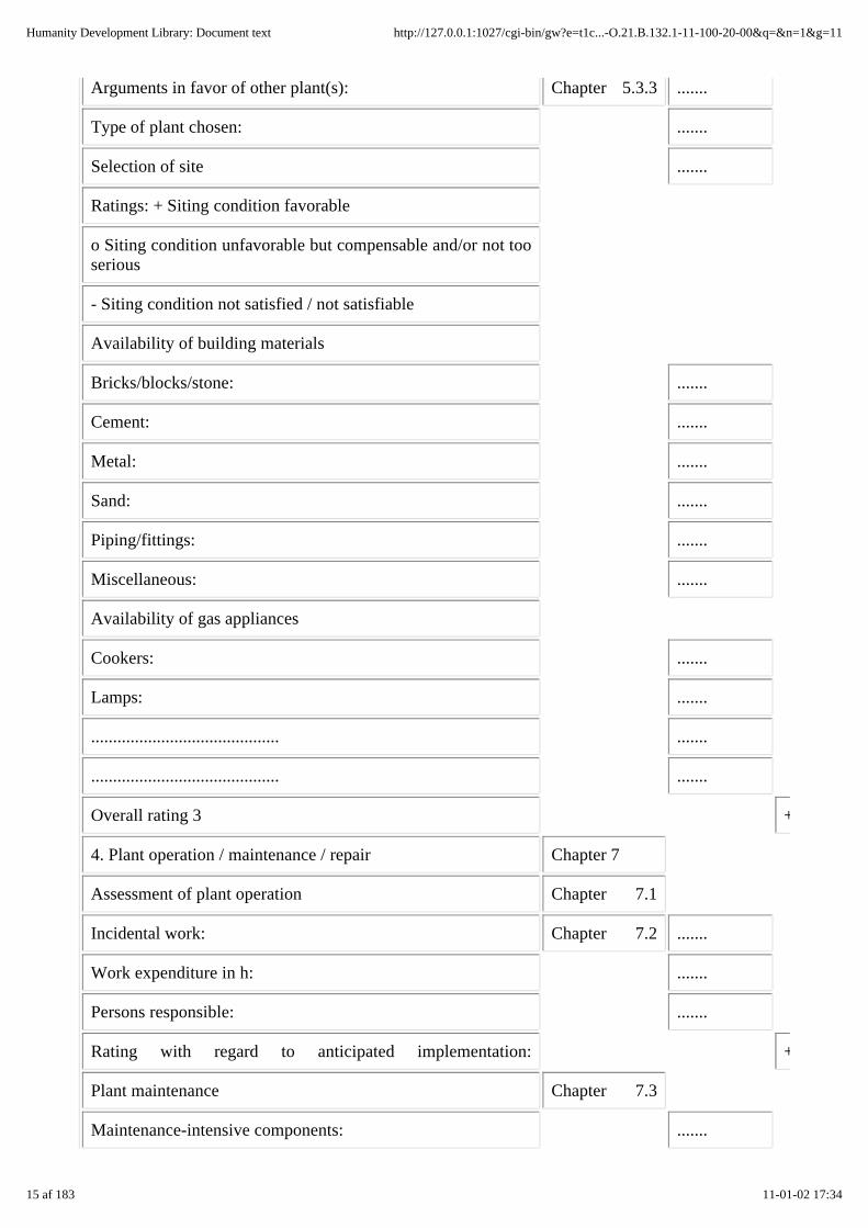
Arguments in favor of other plant(s): Chapter 5.3.3 .......
Type of plant chosen: .......
Selection of site .......
Ratings: + Siting condition favorable
o Siting condition unfavorable but compensable and/or not tooserious
- Siting condition not satisfied / not satisfiable
Availability of building materials
Bricks/blocks/stone: .......
Cement: .......
Metal: .......
Sand: .......
Piping/fittings: .......
Miscellaneous: .......
Availability of gas appliances
Cookers: .......
Lamps: .......
........................................... .......
........................................... .......
Overall rating 3 +
4. Plant operation / maintenance / repair Chapter 7
Assessment of plant operation Chapter 7.1
Incidental work: Chapter 7.2 .......
Work expenditure in h: .......
Persons responsible: .......
Rating with regard to anticipated implementation: +
Plant maintenance Chapter 7.3
Maintenance-intensive components: .......
15 af 183 11-01-02 17:34
Humanity Development Library: Document text http://127.0.0.1:1027/cgi-bin/gw?e=t1c...-O.21.B.132.1-11-100-20-00&q=&n=1&g=11

Maintenance work by user: Table 7.2 .......
Maintenance work by external assistance: .......
Rating with regard to anticipated implementation: +
Plant repair Chapter 7.4
Components liable to need repair: .......
Repairs that can be made by the user: .......
Repairs requiring external assistance: .......
Requisite materials and spare parts:
Rating with regard to expected
repair services: +
Overall rating 4 +
5. Economic analysis Chapter 8
Time-expenditure accounting Chapter 8.2
Time saved with biogas plant Table 8.1 .......
Time lost due to biogas plant .......
Rating:
Ratings: + Siting condition favorable
o Siting condition unfavorable but compensable and/or not tooserious
- Siting condition not satisfied / not satisfiable
Microeconomic analysis Chapter 8.3
Initial investment: Table 8.2 .......
Cost of operation/maintenance/repair: .......
Return on investment:energy, fertilizer, otherwise: .......
Payback time (static): Table 8.3 .......
Productiveness (static): .......
Rating: +
16 af 183 11-01-02 17:34
Humanity Development Library: Document text http://127.0.0.1:1027/cgi-bin/gw?e=t1c...-O.21.B.132.1-11-100-20-00&q=&n=1&g=11

Quality factors, useful socioeconomic effects and costs Chapter 8.5
Useful effects: hygiene, autonomous energy, better
lighting, better working conditions, prestige: .......
Drawbacks: need to handle night soil, negative social impact: .......
Rating: +
Overall rating 5 +
6. Social acceptance and potential for dissemination Chapter 9
Anticipated acceptance Chapter 9.1
Participation in planning and construction: .......
Integration into agricultural setting: .......
Integration into household: . .......
Sociocultural acceptance: .......
Rating: .......
Establishing a dessemination strategy Chapter 9.2
Conditions for and chances of the professional craftsmanapproach:
....... +
Conditions for and chances of the self-help oriented approach: ....... +
General conditions for dissemination
Project-executing organization and its staffing: Chapter 9.3 .......
Organizational structure: .......
interest and prior experience in biogas technology: .......
Regional infrastructure for transportation and communication: .......
material procurement: .......
Craftsman involvement, i.e. Chapter 9.4
which activities: .......
minimum qualifications: .......
tools and machines: .......
Training for engineers, craftsman and users: Chapter 9.5 .......
17 af 183 11-01-02 17:34
Humanity Development Library: Document text http://127.0.0.1:1027/cgi-bin/gw?e=t1c...-O.21.B.132.1-11-100-20-00&q=&n=1&g=11

Ratings: + Siting condition favorable
o Siting condition unfavorable but compensable and/or not tooserious
- Siting condition not satisfied/not satisfiable
Proprietary capital, subsidy/credit requirement
on the part of Chapter 9.6
user: .......
craftsmen: .......
Rating: ....... +
Overall rating 6 ....... +
7. Summarization
Siting conditions No. Rating
Natural/agricultural conditions 1 +
Balancing the energy demand and the biogas production 2 +
Plant design and construction 3 +
Plant operation/maintenance/repair 4 +
Economic analysis 5 +
Social acceptance and potential for dissemination 6 +
Overall rating of siting conditions +
Ratings: + Siting condition favorable
o Siting condition unfavorable but compensable and/or not tooserious
- Siting condition not satisfied / not satisfiable
Following assessment as in table 2.1, the biogas-plant site in question can only be regarded assuitable, if most of the siting factors have a favorable (+) rating. This applies in particularly to item 2,the positive energy balance, meaning that the potential biogas production must cover the gas demand.
If the favorable and unfavorable ratings are fairly well balanced, the more decisive factors should bere-evaluated to determine the extent to which supplementary measures could provide the missingconditions for building and operating a biogas plant despite some reservations but withoutinjustifiable effort. Then, if the overall evaluation does not swing toward the positive side, the plantshould not be built. If the site is given a favorable rating, further planning hints can be taken from the
18 af 183 11-01-02 17:34
Humanity Development Library: Document text http://127.0.0.1:1027/cgi-bin/gw?e=t1c...-O.21.B.132.1-11-100-20-00&q=&n=1&g=11
following checklist.
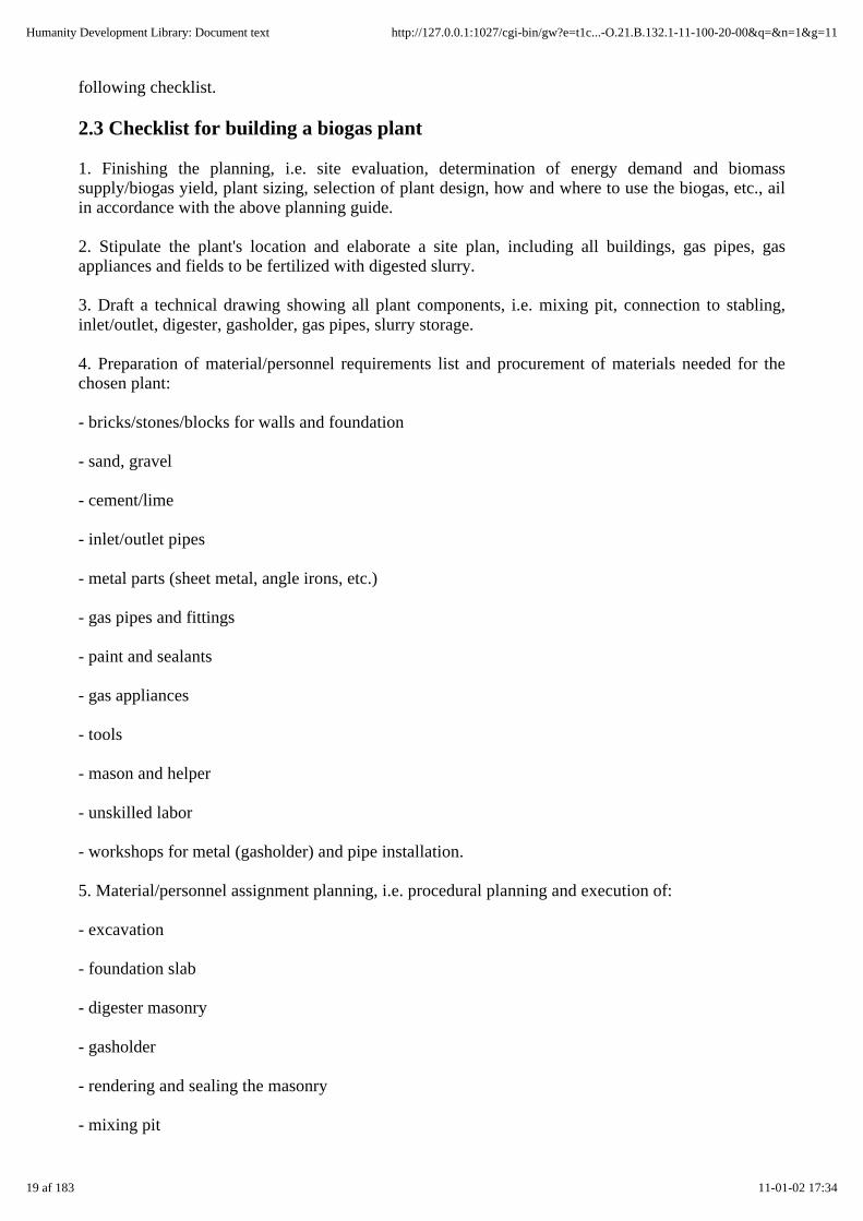
2.3 Checklist for building a biogas plant
1. Finishing the planning, i.e. site evaluation, determination of energy demand and biomasssupply/biogas yield, plant sizing, selection of plant design, how and where to use the biogas, etc., ailin accordance with the above planning guide.
2. Stipulate the plant's location and elaborate a site plan, including all buildings, gas pipes, gasappliances and fields to be fertilized with digested slurry.
3. Draft a technical drawing showing all plant components, i.e. mixing pit, connection to stabling,inlet/outlet, digester, gasholder, gas pipes, slurry storage.
4. Preparation of material/personnel requirements list and procurement of materials needed for thechosen plant:
- bricks/stones/blocks for walls and foundation
- sand, gravel
- cement/lime
- inlet/outlet pipes
- metal parts (sheet metal, angle irons, etc.)
- gas pipes and fittings
- paint and sealants
- gas appliances
- tools
- mason and helper
- unskilled labor
- workshops for metal (gasholder) and pipe installation.
5. Material/personnel assignment planning, i.e. procedural planning and execution of:
- excavation
- foundation slab
- digester masonry
- gasholder
- rendering and sealing the masonry
- mixing pit
19 af 183 11-01-02 17:34
Humanity Development Library: Document text http://127.0.0.1:1027/cgi-bin/gw?e=t1c...-O.21.B.132.1-11-100-20-00&q=&n=1&g=11

- slurry storage pit
- drying out the plant
- installing the gas pipe
- acceptance inspection.
6. Regular building supervision.
7. Commissioning
- functional inspection of the biogas plant and its components - starting the plant
8. Filling the plant.
9. Training the user.
3. The agricultural setting
3.1 Natural parameters for biogas plants of simple design
Climate zones
A minimum temperature of 15 °C is required for anaerobic fermentation of organic material (cf.chapter 5.1). Since simple biogas plants are unheated, they can only be used in climatic zones inwhich the minimum temperature is not fallen short of for any substantial length of time. In general,this is true of the area located between the two tropics, i.e. in the geographic region referred to as the"Tropics".
In the climatic sense, however, the Tropics are inhomogeneous, containing various climatic zoneswith their own typical forms of vegetation and agricultural practices. Proceeding on that basis, it maybe said that a particular zone does or does not qualify as a "biogas zone'' (cf. table 3.1).
With the exception of subtropical arid regions (deserts and semideserts), all tropical climates arecharacterized by:
- increasingly small diurnal and seasonal temperature variation in the direction of the equator,
- decreasing annual rainfall and number of humid months with increasing distance from the equator.
This basic zonal breakdown, though, is altered in several ways by other climatic factors such as wind,elevation and ocean currents. Consequently, the climatic zones serve only as a basis for roughorientation with regard to the climatic evaluation of potential sites for biogas plants. The locallyprevailing climatic conditions are decisive and must be ascertained on the spot.
20 af 183 11-01-02 17:34
Humanity Development Library: Document text http://127.0.0.1:1027/cgi-bin/gw?e=t1c...-O.21.B.132.1-11-100-20-00&q=&n=1&g=11
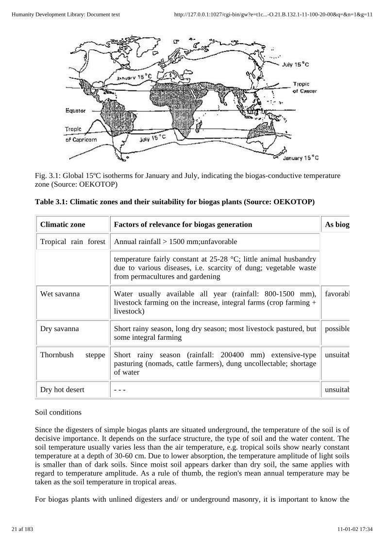
Fig. 3.1: Global 15ºC isotherms for January and July, indicating the biogas-conductive temperaturezone (Source: OEKOTOP)
Table 3.1: Climatic zones and their suitability for biogas plants (Source: OEKOTOP)
Climatic zone Factors of relevance for biogas generation As biogas
Tropical rain forest Annual rainfall > 1500 mm;unfavorable
temperature fairly constant at 25-28 °C; little animal husbandrydue to various diseases, i.e. scarcity of dung; vegetable wastefrom permacultures and gardening
Wet savanna Water usually available all year (rainfall: 800-1500 mm),livestock farming on the increase, integral farms (crop farming +livestock)
favorable
Dry savanna Short rainy season, long dry season; most livestock pastured, butsome integral farming
possible
Thornbush steppe Short rainy season (rainfall: 200400 mm) extensive-typepasturing (nomads, cattle farmers), dung uncollectable; shortageof water
unsuitable
Dry hot desert - - - unsuitable
Soil conditions
Since the digesters of simple biogas plants are situated underground, the temperature of the soil is ofdecisive importance. It depends on the surface structure, the type of soil and the water content. Thesoil temperature usually varies less than the air temperature, e.g. tropical soils show nearly constanttemperature at a depth of 30-60 cm. Due to lower absorption, the temperature amplitude of light soilsis smaller than of dark soils. Since moist soil appears darker than dry soil, the same applies withregard to temperature amplitude. As a rule of thumb, the region's mean annual temperature may betaken as the soil temperature in tropical areas.
For biogas plants with unlined digesters and/ or underground masonry, it is important to know the
21 af 183 11-01-02 17:34
Humanity Development Library: Document text http://127.0.0.1:1027/cgi-bin/gw?e=t1c...-O.21.B.132.1-11-100-20-00&q=&n=1&g=11

stability of the soil structure. The stability of a given soil increases along with the bedding density.Natural soils are generally stable enough for biogas plants. Caution is called for, however, in the caseof alluvial and wet, silty soils. Most of the laterite soil prevailing in the tropics shows high structuralstability and is therefore quite suitable for biogas plants with unlined digesters. Unlined earth pitsusually become more or less impermeable within a short time, but preparatory seepage trials shouldbe conducted in exploratory holes, just to make sure. Previous experience has shown that seepage candrop to below 5% of the initial rate within a week. In the case of large-scale biogas plants, it is alwaysadvisable to have an expert check the soil stability.
Biogas plants should never be located in groundwater, areas subject to flooding, or near wells. On theother hand, an adequate supply of water must be available in the immediate vicinity of the biogasplant, because the substrate must be diluted. If the direction of groundwater flow is known, the biogasplant should be placed downstream of the well.
3.2 Suitable types of biomass and their characteristics
Practically any kind of watery organic substance is suitable for anaerobic digestion. The agriculturalresidues and waste materials that can be used as substrate for biogas plants consist chiefly of:
- waste from animal husbandry, e.g. dung, urine, fodder residue and manure, .
- vegetable waste, e.g. straw, grass, garden residue, etc. (though such materials do not ferment wellalone),
- household waste like night soil, garbage, wastewater, etc.
Solid and liquid agroindustrial waste materials, from slaughterhouses for example, and wastewaterfrom sugar/starch processing are not gone into here, since small-scale biogas plants of simple designwould not suffice in that connection (cf. chapter 6).
Waste from animal husbandry
Most simple biogas plants are "fueled" with manure (dung and urine), because such substratesusually ferment well and produce good biogas yields. Quantity and composition of manure areprimarily dependent on:
- the amount of fodder eaten and its digestibility; on average, 40 - 80% of the organic contentreappears as manure (cattle, for example, excrete approximately 1/3 of their fibrous fodder),
- quality of fodder utilization and the liveweight of the animals.
It is difficult to offer approximate excrement-yield values, because they are subject to wide variation.In the case of cattle, for example, the yield can amount to anywhere from 8 to 40 kg per head and day,depending on the strain in question and the housing intensity. Manure yields should therefore beeither measured or calculated on a liveweight basis, since there is relatively good correlation betweenthe two methods.
The quantities of manure listed in table 3.2 are only then fully available, if all of the anirnals are keptin stables all of the time and if the stables are designed for catching urine as well as dung (cf. chapter3.3).
Thus, the stated values will be in need of correction in most cases. If cattle are only kept in nightstables, only about 1/3 to 1/2 as much manure can be collected. For cattle stalls with litter, the totalyields will include 2 - 3 kg litter per animal and day.
22 af 183 11-01-02 17:34
Humanity Development Library: Document text http://127.0.0.1:1027/cgi-bin/gw?e=t1c...-O.21.B.132.1-11-100-20-00&q=&n=1&g=11
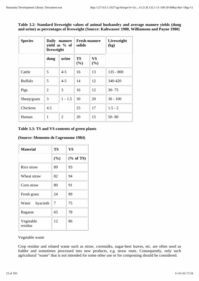
Table 3.2: Standard liveweight values of animal husbandry and average manure yields (dungand urine) as percentages of liveweight (Source: Kaltwasser 1980, Williamson and Payne 1980)
Species Daily manureyield as % ofliveweight
Fresh-manuresolids
Liveweight(kg)
dung urine TS(%)
VS(%)
Cattle 5 4-5 16 13 135 - 800
Buffalo 5 4-5 14 12 340-420
Pigs 2 3 16 12 30- 75
Sheep/goats 3 1 - 1.5 30 20 30 - 100
Chickens 4.5 25 17 1.5 - 2
Human 1 2 20 15 50- 80
Table 3.3: TS and VS-contents of green plants
(Source: Memento de l'agronome 1984)
Material TS VS
(%) (% of TS)
Rice straw 89 93
Wheat straw 82 94
Corn straw 80 91
Fresh grass 24 89
Water hyacinth 7 75
Bagasse 65 78
Vegetableresidue
12 86
Vegetable waste
Crop residue and related waste such as straw, cornstalks, sugar-beet leaves, etc. are often used asfodder and sometimes processed into new products, e.g. straw rnats. Consequently, only suchagricultural "waste" that is not intended for some other use or for composting should be considered.
23 af 183 11-01-02 17:34
Humanity Development Library: Document text http://127.0.0.1:1027/cgi-bin/gw?e=t1c...-O.21.B.132.1-11-100-20-00&q=&n=1&g=11

Most green plants are well-suited for anaerobic fermentation. Their gas yields are high, usually abovethat of manure (cf. table 3.5). Wood and woody parts of plants resist anaerobic fermentation andshould therefore not be used in biogas plants. Due to the poor flow properties of plant material and itstendency to form floating scum, it can only be used alone in a batch-type plant. In practice, however,batch plants are unpopular because of the need for intermittent charging and emptying.
In continuous-type family-size biogas plants, crop residue therefore should only be used as anaddition to animal excrements. Any fibrous material like straw has to be chopped up to 2 - 6cm - andeven that does not fully preclude scum formation.
Table 3.4: Digestion characteristics of animal-husbandry residues (Source: OEKOTOP)
Substrate Scum formation/sedimentation
Digestion Recommendedretention time(days)
Gas yieldcomparedcattle
Cattle manure none none very stable 60- 80 100%
ditto, plus 10%straw
heavy slight very stable 60-100 120%
Pig manure slight toheavy
heavy toslight
Danger of "tilting",i.e. acidification, atthe beginning; slowrun-up with cattlemanure necessary
40 - 60 200%
ditto, plus 10%straw
heavy slight ditto 60 - 80 . . .
Chicken manure slight toheavy
heavy Slow run-upwithcattle manureadvisable; danger of"tilting"
80 200%
Sheep/gcat manuremanure
mediumto heavy
none stable 80-100 80%
Table 3.5: Mean gas yields from various types of agricultural biomass (Source: OEKOTOP,compiled from various sources)
24 af 183 11-01-02 17:34
Humanity Development Library: Document text http://127.0.0.1:1027/cgi-bin/gw?e=t1c...-O.21.B.132.1-11-100-20-00&q=&n=1&g=11

Substrate Gas-yield range (1/kg VS) Average gas yield (1/kgVS)
Pig manure 340-550 450
Cow manure 150-350 250
Poultry manure 310-620 460
Horse manure 200-350 250
Sheep manure 100-310 200
Stable manure 175-320 225
Grain skew 180-320 250
Corn straw 350-480 410
Rice straw 170-280 220
Grass 280-550 410
Elephant grass 330-560 445
Bagasse 140-190 160
Vegetable residue 300-400 350
Water hyacinth 300-350 325
Algae 380-550 460
Sewage sludge 310-640 450
Table 3.6: C/N-ratios of varios substrates (Source: Barnett 1978)
25 af 183 11-01-02 17:34
Humanity Development Library: Document text http://127.0.0.1:1027/cgi-bin/gw?e=t1c...-O.21.B.132.1-11-100-20-00&q=&n=1&g=11

Substrate C/N
Urine 0.8
Cattle dung 10-20
Pig dung 9-13
Chicken manure 5-8
Sheep/goat dung 30
Human excrements 8
Grain straw 80-140
Corn straw 30-65
Fresh grass 12
Water hyacinth 20-30
Vegetable residue 35
Digestion characteristics and gas yields
As long as the total solids content of the substrate does not substantially exceed 10%, simple biogasplants can be expected to operate smoothly on a mixture of animal excrements and plant material(straw, fodder waste).
Manure from ruminants, particularly cattle, is very useful for starting the fermentation process,because it already contains the necessary methanogenic bacteria. On the other hand, the gas yieldfrom cattle dung is lower than that obtained from chickens or pigs, since cattle draw a higherpercentage of nutrients out of the fodder' and the leftover lignin complexes from high-fiber fodder arevery resistant to anaerobic fermentation. Urine, with its low organic content, contributes little to theultimate gas yield but substantially improves the fertilizing effect of the digested slurry and serves indiluting the substrate.
The carbon(C)/nitrogen(N)-ratio of animal and human excrements is normally favorable for thepurposes of anaerobic fermentation (9 - 25:1), while that of plant material usually indicates anexcessive carbon content.
In many cases, various substrates should be mixed together in order to ensure a favorable gas yieldwhile stabilizing the fermentation process and promoting gas production. The following formulae canbe used to calculate the C/N-ratio and total-solids content of a given mixture:
MC/N = [(C/N1 x Wl) + (C/N2 x W2) + . . . + (C/Nn x Wn)]/(W1 + W2 + . . . + Wn)
MTS = [(TSI x Wl) + (TS2 x W2) + . . . + (TSn x Wn)]/(W1 +W2 + ... + Wn)
MC/N = C/N-ratio of mixed substrate, MTS = TS-content of mixed substrate, C/N = C/N-ratio ofindividual substrate, W = weight of individual substrate, TS = TS-content of fresh material.
26 af 183 11-01-02 17:34
Humanity Development Library: Document text http://127.0.0.1:1027/cgi-bin/gw?e=t1c...-O.21.B.132.1-11-100-20-00&q=&n=1&g=11
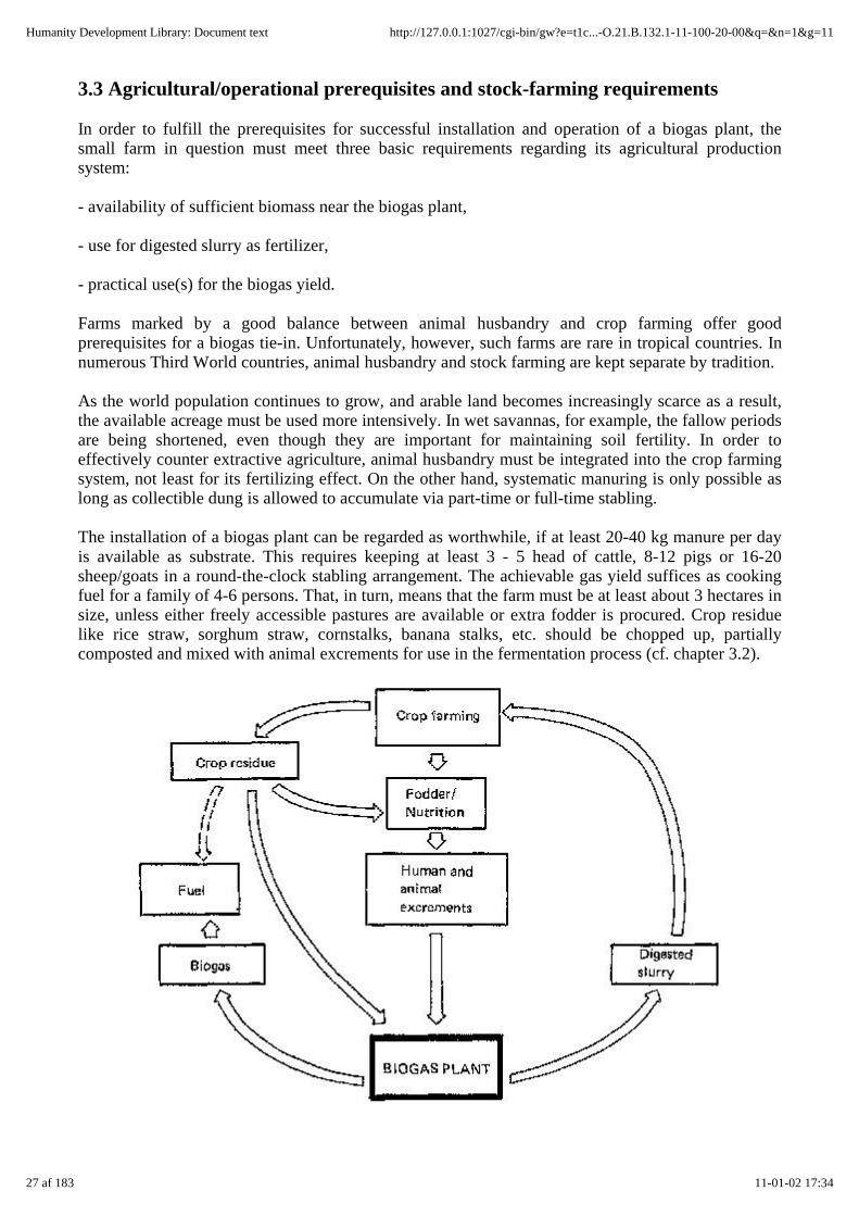
3.3 Agricultural/operational prerequisites and stock-farming requirements
In order to fulfill the prerequisites for successful installation and operation of a biogas plant, thesmall farm in question must meet three basic requirements regarding its agricultural productionsystem:
- availability of sufficient biomass near the biogas plant,
- use for digested slurry as fertilizer,
- practical use(s) for the biogas yield.
Farms marked by a good balance between animal husbandry and crop farming offer goodprerequisites for a biogas tie-in. Unfortunately, however, such farms are rare in tropical countries. Innumerous Third World countries, animal husbandry and stock farming are kept separate by tradition.
As the world population continues to grow, and arable land becomes increasingly scarce as a result,the available acreage must be used more intensively. In wet savannas, for example, the fallow periodsare being shortened, even though they are important for maintaining soil fertility. In order toeffectively counter extractive agriculture, animal husbandry must be integrated into the crop farmingsystem, not least for its fertilizing effect. On the other hand, systematic manuring is only possible aslong as collectible dung is allowed to accumulate via part-time or full-time stabling.
The installation of a biogas plant can be regarded as worthwhile, if at least 20-40 kg manure per dayis available as substrate. This requires keeping at least 3 - 5 head of cattle, 8-12 pigs or 16-20sheep/goats in a round-the-clock stabling arrangement. The achievable gas yield suffices as cookingfuel for a family of 4-6 persons. That, in turn, means that the farm must be at least about 3 hectares insize, unless either freely accessible pastures are available or extra fodder is procured. Crop residuelike rice straw, sorghum straw, cornstalks, banana stalks, etc. should be chopped up, partiallycomposted and mixed with animal excrements for use in the fermentation process (cf. chapter 3.2).
27 af 183 11-01-02 17:34
Humanity Development Library: Document text http://127.0.0.1:1027/cgi-bin/gw?e=t1c...-O.21.B.132.1-11-100-20-00&q=&n=1&g=11

Fig. 3.2: Integration of a biogas plant into the agricultural production cycle (Source: OEKOTOP)
Table 3.7: Biogas compatibility of farm types (Source: OEKOTOP)
Type of farm Characteristics of relevance to biogasgeneration
Rating as site for biogas
Stock farming only Pasturing (nomadic, ranching, etc.) Intensive stationary fattening
unsuitable suitable
Crop farming only Crop residue only; fermentation difficult normally unsuitable
Mixed Agriculture
Stock farming for:
- animal power Mostly nighttime stabling; only a few animals;50% of dung collectible
possible
- meat production
extensive Pasturing; no stabling; dung wasted unsuitable
intensive Fattening in stables; dung directly usable suitable
- milk production Frequently permanent stabling; all dung andurine usable
suitable
Crop farming:
- vegetables Near house; crop residue and water availableyear-round
possible!
- field-tilling
unirrigated 1 harvest per year, scarcity of fodder,long-distance hauling of water and manure
unsuitable
irrigated 2-3 harvests per year; water available, smallfields
possible
Adding a biogas plant to an integrated agricultural production system not only helps save firewoodand preserve forests, but also contributes toward sustained soil fertility through organic fertilizationand ensures the long-term crop-bearing capacity of the soil. Work involving the dissemination ofbiogas. technologies must account for and call attention to that complex relationship. If no organicfertilizing has been done before, a biogas plant will mean more work. Organic waste has to becollected and afterwards spread on the fields. Only if the owner is willing to invest the extra effortcan the biogas plant be expected to serve well in the long term.
There are two central demands to be placed on the stock-farming system in relation to biogasutilization:
- permanent or part-time stabling or penning and
28 af 183 11-01-02 17:34
Humanity Development Library: Document text http://127.0.0.1:1027/cgi-bin/gw?e=t1c...-O.21.B.132.1-11-100-20-00&q=&n=1&g=11
- proximity of the stables or pens to the place of gas utilization (usually the farmhouse).
If the distance between the stables/pens and the place of gas utilization is considerable, either thesubstrate must be hauled to the biogas plant (extra work) or the gas must be transferred to the place ofuse (cost of installing a supply pipe). Either of the two would probably doom the biogas plant tofailure. The best set of circumstances is given, when
- the animal excrements can flow directly into the biogas plant by exploiting a natural gradient,
- the distance of flow is short, and
- the stables have a concrete floor to keep contamination like soil and sand from getting into the plantwhile allowing collection of urine.
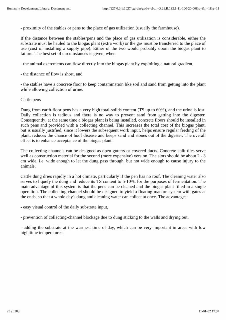
Cattle pens
Dung from earth-floor pens has a very high total-solids content (TS up to 60%), and the urine is lost.Daily collection is tedious and there is no way to prevent sand from getting into the digester.Consequently, at the same time a biogas plant is being installed, concrete floors should be installed insuch pens and provided with a collecting channel. This increases the total cost of the biogas plant,but is usually justified, since it lowers the subsequent work input, helps ensure regular feeding of theplant, reduces the chance of hoof disease and keeps sand and stones out of the digester. The overalleffect is to enhance acceptance of the biogas plant.
The collecting channels can be designed as open gutters or covered ducts. Concrete split tiles servewell as construction material for the second (more expensive) version. The slots should be about 2 - 3cm wide, i.e. wide enough to let the dung pass through, but not wide enough to cause injury to theanimals.
Cattle dung dries rapidly in a hot climate, particularly if the pen has no roof. The cleaning water alsoserves to liquefy the dung and reduce its TS content to 5-10%. for the purposes of fermentation. Themain advantage of this system is that the pens can be cleaned and the biogas plant filled in a singleoperation. The collecting channel should be designed to yield a floating-manure system with gates atthe ends, so that a whole day's dung and cleaning water can collect at once. The advantages:
- easy visual control of the daily substrate input,
- prevention of collecting-channel blockage due to dung sticking to the walls and drying out,
- adding the substrate at the warmest time of day, which can be very important in areas with lownighttime temperatures.
29 af 183 11-01-02 17:34
Humanity Development Library: Document text http://127.0.0.1:1027/cgi-bin/gw?e=t1c...-O.21.B.132.1-11-100-20-00&q=&n=1&g=11
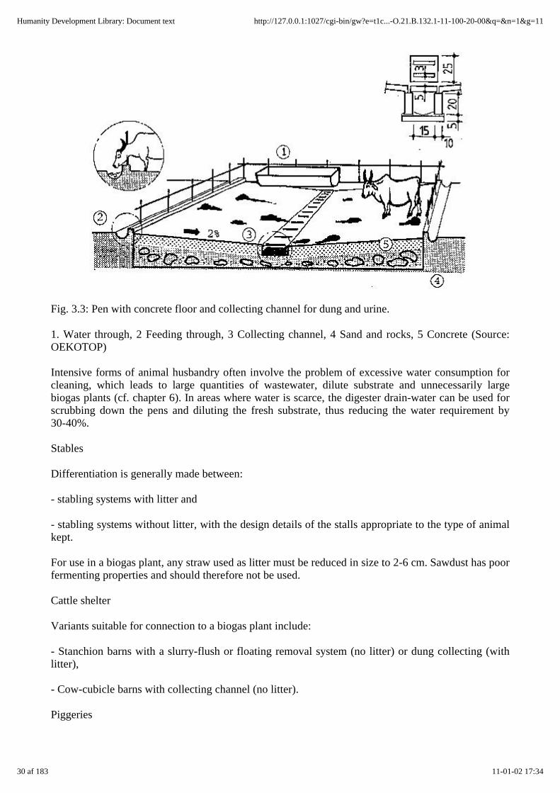
Fig. 3.3: Pen with concrete floor and collecting channel for dung and urine.
1. Water through, 2 Feeding through, 3 Collecting channel, 4 Sand and rocks, 5 Concrete (Source:OEKOTOP)
Intensive forms of animal husbandry often involve the problem of excessive water consumption forcleaning, which leads to large quantities of wastewater, dilute substrate and unnecessarily largebiogas plants (cf. chapter 6). In areas where water is scarce, the digester drain-water can be used forscrubbing down the pens and diluting the fresh substrate, thus reducing the water requirement by30-40%.
Stables
Differentiation is generally made between:
- stabling systems with litter and
- stabling systems without litter, with the design details of the stalls appropriate to the type of animalkept.
For use in a biogas plant, any straw used as litter must be reduced in size to 2-6 cm. Sawdust has poorfermenting properties and should therefore not be used.
Cattle shelter
Variants suitable for connection to a biogas plant include:
- Stanchion barns with a slurry-flush or floating removal system (no litter) or dung collecting (withlitter),
- Cow-cubicle barns with collecting channel (no litter).
Piggeries
30 af 183 11-01-02 17:34
Humanity Development Library: Document text http://127.0.0.1:1027/cgi-bin/gw?e=t1c...-O.21.B.132.1-11-100-20-00&q=&n=1&g=11
The following options are well-suited for combination with a biogas plant:
- barns with fully or partially slotted floors (no litter),
- lying bays with manure gutter (no litter),
- group bays (with or without litter).
Fig. 3.4: Stanchion barn with floating gutter. 1 Collecting channel, 2 Stable, 3 Floating gutter leadingto the biogas plant, 4 feeding aisle, 5 Feeding trough (Source: OEKOTOP)
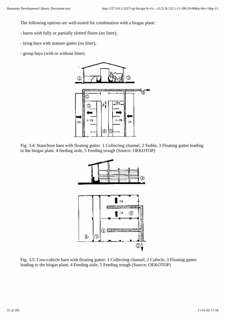
Fig. 3.5: Cow-cubicle barn with floating gutter. 1 Collecting channel, 2 Cubicle, 3 Floating gutterleading to the biogas plant, 4 Feeding aisle, 5 Feeding trough (Source: OEKOTOP)
31 af 183 11-01-02 17:34
Humanity Development Library: Document text http://127.0.0.1:1027/cgi-bin/gw?e=t1c...-O.21.B.132.1-11-100-20-00&q=&n=1&g=11

Fig. 3.6: Piggery with group bays (no litter). 1 Feeding aisle, 2 Feeding trough, 3 Floating gutterleading to the biogas plant, 4 Bay (pigpen) (Source: Manuel et Preas D levage No. 3, 1977)
Liquid manure from swine normally has better flow properties than liquid manure from cattle, themain reason being that swine eat less fibrous material. Additionally, though, swine drop more urinethan dung.
In tropical countries, few pigsties have fully or partially slotted floors. Most pigs are kept in groupbays. Figure 3.6 shows a schematic representation of a piggery with bays of different size toaccommodate animals of various weight categories. The animals are moved in groups from one bayto the next as they grow.
Chicken coops
Hens kept in battery-brooding cages never have litter. Despite the name, straw yards can be managedwith or without litter.
In either system, the dry droppings are collected, transferred to the biogas plant and diluted to makethem flowable. Feathers and sand are always problematic, since they successfully resist removal fromthe substrate. In many cases, the coop is only cleaned and disinfected once after the entire populationis slaughtered. As a rule such systems are not suitable as a source of substrate for biogas plants.
3.4 Fertilizing with digested slurry
The practice of regular organic fertilizing is still extensively unknown in most tropical andsubtropical countries. Due, however, to steady intensification of agricultural methods, e.g.abbreviated fallow intervals, some form of purposeful organic fertilizing, naturally including the useof digested slurry as fertilizer, would be particularly useful as a means of maintaining tropical soilfertility. Since Third World farmers have little knowledge of or experience in organic fertilizingmethods, particularly with regard to the use of digested slurry, the scope of the following discussionis limited to the general plantgrowth efficiency factors of digested slurry.
Fermentation-induced modification of substrate
- Anaerobic digestion draws carbon, hydrogen and oxygen out of the substrate. The essential plantnutrients (N, P, K) remain, at least in principle, in place. The composition of fertilizing agents indigested slurry depends on the source material and therefore can be manipulated within certain limits.
- For all practical purposes, the volume of the source material remains unchanged, since only some35 - 50% of the organic substances (corresponding to 5 - 10% of the total volume) is converted togas.
32 af 183 11-01-02 17:35
Humanity Development Library: Document text http://127.0.0.1:1027/cgi-bin/gw?e=t1c...-O.21.B.132.1-11-100-20-00&q=&n=1&g=11

- Fermentation reduces the C/N-ratio by removing some of the carbon, which has the advantage ofincreasing the fertilizing effect. Another favorable effect is that organically fixed nitrogen and otherplant nutrients become mineralized and, hence, more readily available to the plants.
- Well-digested slurry is practically oderless and does not attract flies.
- Anaerobic digestion kills off or at least deactivates pathogens and worm ova, though the effectcannot necessarily be referred to as hygienization (cf. Table 3.8). Ninety-five percent of the ova andpathogens accumulate in the scum and sediment. Plant seeds normally remain more or lessunaffected.
- Compared to the source material, digested slurry has a finer, more homogeneous structure, whichmakes it easier to spread.
Table 3.8: Survival time of pathogens in biogas plants (Source: Anaerobic Digestion 1985)
Bacteria Thermophilicfermentation
Mesophilicfermentation
Psycrophilicfermentation
53-55 °C 35-37°C
8-25 °C
Fatality Fatality Fatality
Days Rate Days Rate Days Rate
(%) (%) (%)
Salmonella 1-2 100.0 7 100.0 44 100.0
Shigella 1 100.0 5 100.0 30 100.0
Poliviruses 9 100.0
Schistosomaova
hours 100.0 7 100.0 7-22 100.0
Hookworm ova 1 100.0 10 100.0 30 90.0
Ascaris ova 2 100.0 36 98.8 100 53.0
Colititre 2 10-1 - 10-2 21 10-4 40-60 10-5 -10-4
Table 3.9: Concentration of nutrients in the digested slurry of various substrates!
(Source: OEKOTOP, compiled from various sources)
33 af 183 11-01-02 17:35
Humanity Development Library: Document text http://127.0.0.1:1027/cgi-bin/gw?e=t1c...-O.21.B.132.1-11-100-20-00&q=&n=1&g=11

Type ofsubstrate
N P2O5 K2O CaO MgO
—% TS—
Cattle dung 2.3 - 4.7 0.9 - 2.1 4.2 - 7.6 1.0 - 4.2 0.6 - 1.1
Pig dung 4.1 - 8.4 2.6 - 6.9 1.6 - 5.1 2.5 - 5.7 0.8 - 1.1
Chickenmanure
4.3 - 9.5 2.8 - 8.1 2.1 - 5.3 7.3 - 13.2 1.1 - 1.6
Fertilizing properties
The fertilizing properties of digested slurry are determined by how much mineral substances andtrace elements it contains; in tropical soil, the nitrogen content is not necessarily of primeimportance—lateritic soils, for example, are more likely to suffer from a lack of phosphorus. Theorganic content of digested slurry improves the soil's texture, stabilizes its humic content, intensifiesits rate of nutrient-depot formation and increases its water-holding capacity. It should be noted that agood water balance is very important in organically fertilized soil, i.e. a shortage of water can wipeout the fertilizing effect.
Very few data on yields and doses are presently available with regard to fertilizing with digestedslurry, mainly because sound scientific knowledge and information on practical experience arelacking in this very broad domain. Table 3.10 lists some yield data on digested-slurry fertilizing inthe People's Republic of China.
For a practician faced with the task of putting digested slurry to good use, the following tendentialobservations may be helpful:
- While the nitrogen content of digested slurry is made more readily available to the plants throughthe mineralization process, the yield effect of digested slurry differs only slightly from that of freshsubstrate (liquid manure). This is chiefly attributable to nitrogen losses occurring at the time ofdistribution.
- Digested slurry is most effective when it is spread on the fields just prior to the beginning of thevegetation period. Additional doses can be given periodically during the growth phase, with theamounts and timing depending on the crop in question. For reasons of hygiene, however, lettuce andvegetables should not be top-dressed.
- The recommended quantities of application are roughly equal for digested slurry and stored liquidmanure.
- The requisite amount of digested-slurry fertilizer per unit area can be determined as a mineralequivalent, e.g. N-equivalent fertilization. The N, P and K doses depend on specific croprequirements as listed in the appropriate regional fertilizing tables.
With a view to improving the overall effect of slurry fertilizer under the prevailing local boundaryconditions, the implementation of a biogas project should include demonstration trials aimed atdeveloping a regionally appropriate mode of digested-slurry application. For information onexperimental systems, please refer to chapter 10.6 - Selected Literature.
Proceeding on the assumption that the soil should receive as much fertilizer as needed to replace the
34 af 183 11-01-02 17:35
Humanity Development Library: Document text http://127.0.0.1:1027/cgi-bin/gw?e=t1c...-O.21.B.132.1-11-100-20-00&q=&n=1&g=11

nutrients that were extracted at harvesting time, each hectare will require an average dose of about 33kg N, 11 kg P2O5 and 48 kg K2O to compensate for an annual yield of 1 - 1.2 tons of, say, sorghumor peanuts. Depending on the nutritive content of the digested slurry, 3-6 t of solid substance perhectare will be required to cover the deficit. For slurry with a moisture content of 90%, the requiredquantity comes to 30-60 t per hectare and year. That roughly corresponds to the annual capacity of a6-8 m³ biogas plant.
Like all other forms of organic fertilizing, digested slurry increases the humic content of the soil, andthat is especially important in low-humus tropical soils. Humus improves the soil's physicalproperties, e.g. its aeration, water retention capacity, permeability, cation-exchange capacity, etc.Moreover, digested slurry is a source of energy and nutrients for soil-inhabiting microorganisms,which in turn make essential nutrients more available to the plants. Organic fertilizers areindispensable for maintaining soil fertility, most particularly in tropical areas.
Table 3.10: Effects of digested slurry on crop yields (Source: Chengdu 1980)
Plants tested Quantity of digestedslurry
Yield Increase
withdigestedslurry
withliquidmanure
(m³ /ha) (kg/ha) (kg/ha) (%)
Sweet potatoes 17 24000 21500 21500 12
Rice 15 6500 6000 500 8
corn (maize) 22.5 5000 4600 400 9
Cotton 22.5 1300 1200 100 8
The importance of digested slurry as a fertilizer is underlined by the answers to the followingquestions:
- How much chemical fertilizer cap be saved with no drop in yield?
- Which yield levels can be achieved by fertilizing with digested slurry, as compared to the sameamount of undigested material, e.g. stored or fermented liquid manure?
- By how much can yields be increased over those from previously unfertilized soil? Depending onthose answers, a certain monetary value can be attached to digested slurry, whereas the laborinvolved in preparing and applying the fertilizer must be given due consideration.
Storing and application of digested slurry
With a view to retaining the fertilizing quality of digested slurry, it should be stored only briefly inliquid form in a closed pit or tank and then applied to the fields. Liquid storage involves a certain lossof nitrogen due to the evaporation of ammonia. For that reason, and in order to limit the size of therequired storage vessels (a 30-day supply corresponds to about 50% of the biogas plant volume), thestorage period should be limited to 2-4 weeks. The resultant quasi-continuous mode of fieldfertilization (each 2-4 weeks), however, is in opposition to the standing criteria of optimum
35 af 183 11-01-02 17:35
Humanity Development Library: Document text http://127.0.0.1:1027/cgi-bin/gw?e=t1c...-O.21.B.132.1-11-100-20-00&q=&n=1&g=11

application, according to which fertilizer should only be applied 2-4 times per year, and then onlyduring the plants' growth phase, when they are able to best exploit the additional nutrient supply.
Fig. 3.7: Slurry storage and composting. 1 Biogas plant, 2 Slurry composting pit with green cover 3Masonry storage pit (V = 10 Sd), 31 Sturdy wooden cover, 32 Overflow (Source: OEKOTOP)
The practice of spreading liquid digested slurry also presents problems in that not only storage tanksare needed, but transport vessels as well, and the amount of work involved depends in part on howfar the digested slurry has to be transported. For example, transporting 1 ton of dung a distance of500 m in an oxcart takes about 5 hours (200 kg per trip). Distributing the dung over the fieldsrequires another 3 hours or so.
If, for reasons of economy and efficiency, liquid fertilizing should appear impractical' the digestedslurry can be mixed with green material and composted. This would involve nitrogen lossesamounting to 30 - 70%. On the other hand, the finished compost would be soil-moist, compact (spadeable) and much easier to transport.
If irrigated fields are located nearby, the digested slurry could be introduced into the irrigating systemso that it is distributed periodically along with the irrigating water.
3.5 Integral agriculture
Integral agriculture, also referred to as biological or ecological farming, aims to achieve effective,low-cost production within a system of integrated cycles. Here, biogas technology can provide thelink between animal husbandry and crop farming.
36 af 183 11-01-02 17:35
Humanity Development Library: Document text http://127.0.0.1:1027/cgi-bin/gw?e=t1c...-O.21.B.132.1-11-100-20-00&q=&n=1&g=11
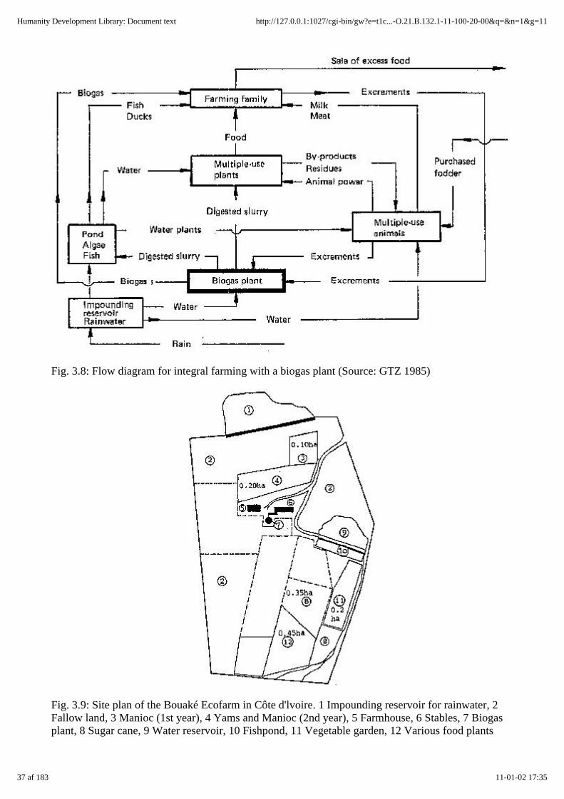
Fig. 3.8: Flow diagram for integral farming with a biogas plant (Source: GTZ 1985)
Fig. 3.9: Site plan of the Bouaké Ecofarm in Côte d'lvoire. 1 Impounding reservoir for rainwater, 2Fallow land, 3 Manioc (1st year), 4 Yams and Manioc (2nd year), 5 Farmhouse, 6 Stables, 7 Biogasplant, 8 Sugar cane, 9 Water reservoir, 10 Fishpond, 11 Vegetable garden, 12 Various food plants
37 af 183 11-01-02 17:35
Humanity Development Library: Document text http://127.0.0.1:1027/cgi-bin/gw?e=t1c...-O.21.B.132.1-11-100-20-00&q=&n=1&g=11

(Source: GTZ 1985)
Consider, for example, the planning of a GTZ project in Cote d'Ivoire. The project included thedevelopment of a model farm intended to exploit as efficiently as possible the natural resources soil,water, solar energy and airborne nitrogen.
The integral agricultural system "Eco-ferme" (ecofarm) comprises the production elements gardening,crop farming (for food and animal fodder), stock farming (for meat and milk) and a fishpond. Acentral component of such closed-loop agricultural production is the biogas plant, which producesboth household energy and digested slurry for use in the fishpond and as a fertilizer.
The average family-size "eco-ferme" has 3 ha of farmland with the following crops:
Fodder plants
Panicum (for the rainy season) 0.15 ha
Sugar cane (for the dry season) 0.50 ha
Leucaena and brachiaria (mixed culture) 0.50 ha
Panicum, brachiaria and centrosema (mixedculture)
0.50 ha
Food plants
Manioc 0.20 ha
Corn 0.40 ha
Yams 0.10 ha
Potatoes - beans 0.10 ha
Vegetables 0.20 ha
Rice and miscellaneous crops 0.17 ha
Four milk cows and three calves are kept year-round in stables. The cattle dung flows via collectingchannels directly into a 13 m³ biogas plant. The biogas plant produces 3.5-4 m³ biogas daily forcooking and lighting. Part of the digested slurry is allowed to flow down the natural gradient into an800 m² fishpond in order to promote the growth of algae, which serves as fish food. The remainingdigested slurry is used as crop fertilizer.
4. Balancing the energy demand with the biogas production
All extension-service advice concerning agricultural biogas plants must begin with an estimation ofthe quantitative and qualitative energy requirements of the interested party. Then, thebiogas-generating potential must be calculated on the basis of the given biomass incidence andcompared to the energy demand. Both the energy demand and the gas-generating potential, however,are variables that cannot be very accurately determined in the planning phase.
In the case of a family-size biogas plant intended primarily as a source of energy, implementation
38 af 183 11-01-02 17:35
Humanity Development Library: Document text http://127.0.0.1:1027/cgi-bin/gw?e=t1c...-O.21.B.132.1-11-100-20-00&q=&n=1&g=11

should only be recommended, if the plant can be expected to cover the calculated energy demand.
Since determination of the biogas production volume depends in part on the size of' the biogas plant,that aspect is included in this chapter.
Fig. 4.1: Balancing the energy demand with the biogas production (Source: OEKOTOP)
4.1 Determining the Energy Demand
The energy demand of any given farm is equal to the sum of all present and future consumptionsituations, i.e. cooking, lighting, cooling, power generation, etc. With deference to the generalorientation of this manual, emphasis is placed on determining the energy demand of a typical familyfarm.
Experience shows that parallel calculations according to different methods can be useful in avoidingerrors in calculating the gas/ energy demand.
Table 4.1: Outline for determining biogas demand (Source: OEKOTOP)
Energy consumers data Biogas demand
(l/d)
1. Gas for cooking (Chapter 5.5.3)
Number of persons .............
Number of meals .............
39 af 183 11-01-02 17:35
Humanity Development Library: Document text http://127.0.0.1:1027/cgi-bin/gw?e=t1c...-O.21.B.132.1-11-100-20-00&q=&n=1&g=11

Present energy consumption .............
Present source of energy .............
Gas demand per person and meal (Table 5.17) .............
Gas demand per meal .............
Anticipated gas demand ...............
Specific consumption rate of burner .............
Number of burners - .............
Duration of burner operation .............
Anticipated gas demand ...............
Total anticipated cooking-gas demand ...............
2. Lighting (Chapter 5.5.3)
Specific gas consumption per lamp (Table 5.20) .............
Number of lamps .............
Duration of lamp operation .............
Gas demand ...............
3. Cooling (Chapter 5.5.3)
Specific gas consumption X 24 h (Table 5.22) ............. ...............
4. Engines (Chapter 5.5.4)
Specific gas consumption per kWh .............
Engine output .............
Operating time .............
Gas demand ...............
5. Miscellaneous consumers
Gas demand ............. ...............
Anticipated increase in consumption (%) ...............
Total biogas demand ...............
1st-priority consumers ...............
40 af 183 11-01-02 17:35
Humanity Development Library: Document text http://127.0.0.1:1027/cgi-bin/gw?e=t1c...-O.21.B.132.1-11-100-20-00&q=&n=1&g=11
2nd-priority consumers ...............
3rd-priority consumers ...............
The following alternative modes of calculation are useful:
Determining biogas demand on the basis of present consumption
. . ., e.g. for ascertaining the cooking-energy demand. This involves either measuring or inquiring asto the present rate of energy consumption in the form of wood/charcoal, kerosene and/or bottled gas.
Calculating biogas demand via comparable-use data
Such data may consist of:
- empirical values from neighboring systems, e.g. biogas consumption per person and meal,
- reference data taken from pertinent literature (cf. chapter 5.5), although this approach involvesconsiderable uncertainty, since cooking-energy consumption depends on local culture-dependentcooking and eating habits and can therefore differ substantially from case to case.
Estimating biogas demand by way of appliance consumption data and assumed periods of use
This approach can only work to the extent that the appliances to be used are known in advance, e.g. abiogas lamp with a specific gas consumption of 1201/h and a planned operating period of 3 in/d,resulting in a gas demand of 360 l/d.
Then, the interested party's energy demand should be tabulated in the form of a requirements list (cf.table 4.1). In that connection, it is very important to attach relative priority values to the variousconsumers, e.g.:
1st priority: applies only when the biogas plant will cover the demand.
2nd priority: coverage is desirable, since it would promote plant usage.
3rd priority: excess biogas can be put to these uses.
4.2 Determining the biogas production
The quantity, quality and type of biomass available for use in the biogas plant constitutes the basicfactor of biogas generation. The biogas incidence can and should also be calculated according todifferent methods applied in parallel.
Measuring the biomass incidence (quantities of excrement and green substrate)
This is a time-consuming, somewhat tedious approach, but it is also a necessary means of adaptingvalues from pertinent literature to unknown regions. The method is rather inaccurate if no total-solidsmeasuring is included. Direct measurement can, however, provide indication of seasonal orfodder-related variance if sufficiently long series of measurements are conducted.
Determining the biomass supply via pertinent-literature data
(cf. tables 3.2/3.3)
41 af 183 11-01-02 17:35
Humanity Development Library: Document text http://127.0.0.1:1027/cgi-bin/gw?e=t1c...-O.21.B.132.1-11-100-20-00&q=&n=1&g=11
According to this method, the biomass incidence can be determined at once on the basis of thelivestock inventory. Data concerning how much manure is produced by different species and perliveweight of the livestock unit are considered preferable.
Dung yield = liveweight (kg) x no. of animals x specific quantity of excrements (in % of liveweightper day, in the form of moist mass, TS or VS).
Determining the biomass incidence via regional reference data
This approach leads to relatively accurate information, as long as other biogas plants are already inoperation within the area in question.
Determining biomass incidence via user survey
This approach is necessary if green matter is to be included as substrate.
It should be kept in mind that the various methods of calculation can yield quite disparate results thatnot only require averaging by the planner, but which are also subject to seasonal variation.
The biomass supply should be divided into two categories:
Category 1: quick and easy to procure,
Category 2: procurement difficult, involving a substantial amount of extra work.
Table 4.2: Outline for determining biomass incidence (Source: OEKOTOP)
42 af 183 11-01-02 17:35
Humanity Development Library: Document text http://127.0.0.1:1027/cgi-bin/gw?e=t1c...-O.21.B.132.1-11-100-20-00&q=&n=1&g=11
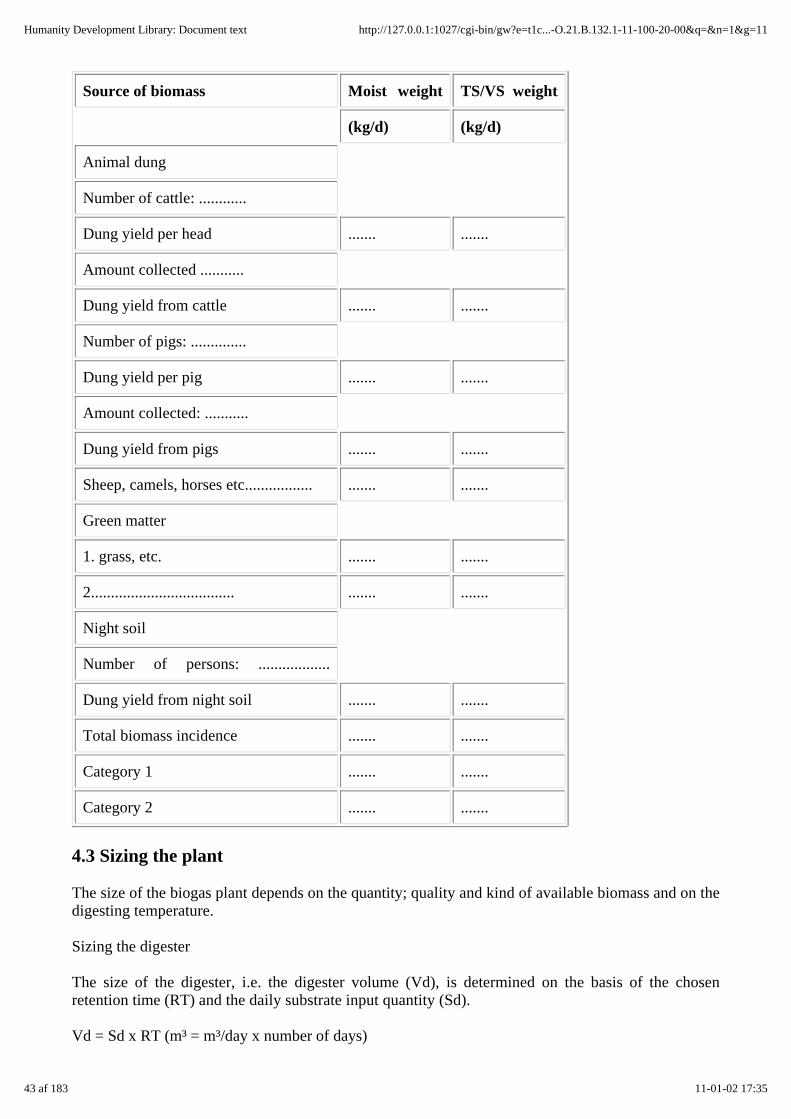
Source of biomass Moist weight TS/VS weight
(kg/d) (kg/d)
Animal dung
Number of cattle: ............
Dung yield per head ....... .......
Amount collected ...........
Dung yield from cattle ....... .......
Number of pigs: ..............
Dung yield per pig ....... .......
Amount collected: ...........
Dung yield from pigs ....... .......
Sheep, camels, horses etc................. ....... .......
Green matter
1. grass, etc. ....... .......
2.................................... ....... .......
Night soil
Number of persons: ..................
Dung yield from night soil ....... .......
Total biomass incidence ....... .......
Category 1 ....... .......
Category 2 ....... .......
4.3 Sizing the plant
The size of the biogas plant depends on the quantity; quality and kind of available biomass and on thedigesting temperature.
Sizing the digester
The size of the digester, i.e. the digester volume (Vd), is determined on the basis of the chosenretention time (RT) and the daily substrate input quantity (Sd).
Vd = Sd x RT (m³ = m³/day x number of days)
43 af 183 11-01-02 17:35
Humanity Development Library: Document text http://127.0.0.1:1027/cgi-bin/gw?e=t1c...-O.21.B.132.1-11-100-20-00&q=&n=1&g=11
The retention time, in turn, is determined by the chosen/given digesting temperature (cf. fig 5.2).
For an unheated biogas plant, the temperature prevailing in the digester can be assumed as 1-2 Kabove the soil temperature. Seasonal variation must be given due consideration, however, i.e. thedigester must be sized for the least favorable season of the year. For a plant of simple design, theretention time should amount to at least 40 days. Practical experience shows that retention times of60-80 days, or even 100 days or more, are no rarity when there is a shortage of substrate. On the otherhand, extra-long retention times can increase the gas yield by as much as 40%.
The substrate input depends on how much water has to be added to the substrate in order to arrive ata solids content of 4-8%.
Substrate input (Sd) = biomass (B) + water (W) (m³/d)
In most agricultural biogas plants, the mixing ratio for dung (cattle and/or pigs) and water (B: W)amounts to between 1: 3 and 2: 1 (cf. table 5.7).
Calculating the daily gas production (G)
The amount of biogas generated each day (G, m³ gas/d), is calculated on the basis of the specific gasyield (Gy) of the substrate and the daily substrate input (Sd).
The calculation can be based on:
a) The volatile-solids content
G = kg VS-input x spec. Gy (solids)
b) the weight of the moist mass
G = kg biomass x spec. Gy (moist mass)
c) standard gas-yield values per livestock unit (LSU)
G = no. of LSU x spec. Gy (species)
Table 4.3 lists simplified gas-yield values for cattle and pigs. A more accurate estimate can be arrivedat by combining the gas-yield values from, say, table 3.5 with the correction factors for digestertemperature and retention time shown in figure 5.2.
GYT,RT = mGy x fT,RT
GYT,RT = gas yield as a function of digester temperature and retention time
mGy = average specific gas yield, e.g. 1/kg VS (table 3.5)
fT,RT = multiplier for the gas yield as a function of digester temperature and retention time (cf. fig.5.2)
As a rule, it is advisable to calculate according to several different methods, since the available basicdata are usually very imprecise, so that a higher degree of sizing certainty can be achieved bycomparing and averaging the results.
44 af 183 11-01-02 17:35
Humanity Development Library: Document text http://127.0.0.1:1027/cgi-bin/gw?e=t1c...-O.21.B.132.1-11-100-20-00&q=&n=1&g=11

Establishing the plant parameters
The degree of safe-sizing certainty can be increased by defining a number of plant parameters:
Specific gas production (Gp)
i.e. the daily gas-generation rate per m³ digester volume (Vd), is calculated according to the followingequation:
Gp = G: Vd (m³ gas/m³ Vd x d)
Digester loading (Ld)
Ld - TS (VS) input/m³ digester volume (kg TS (VS)/m³ Vd x d)
Then, a calculated parameter should be checked against data from comparable plants in the region orfrom pertinent literature.
Table 4.3: Simplified gas-yield values for substrate from cattle and pigs (digesting temperature:22-27 °C) (Source: OEKOTOP)
Type of housing/manure
Cattle, live wt. 200 - 300 kg Buffalo, live wt. 300 - 450 kg
manureyield
Gas yield (I/d) manureyield
Gas yield (I/d)
(kg/d) RT=60 RT=80 (kg/d) RT=60 RRT=80
24-h stabling
- dung only(moist),unpaved floor(10% losses)
9-13 300-450 350-500 14-18 450-540 300-620
- dung andurine,concrete floor
20-30 350-510 450-610 30-40 450-600 5440-710
- stable manure (dung +2 kg litter), concretefloor
22-32 450-630 530-730 32-42 550-740 630-890
Overnight stabling
- dung only (10%losses)
5-8 180-270 220-310 8-10 240-300 2290-360
- dung andurine,concrete floor
11-16 220-320 260-380 16-20 260-330 330-410
1 kg/d moist dung ~35 ~40 ~34 ~40
1 l/d manure ~20 ~25 ~20 ~24
45 af 183 11-01-02 17:35
Humanity Development Library: Document text http://127.0.0.1:1027/cgi-bin/gw?e=t1c...-O.21.B.132.1-11-100-20-00&q=&n=1&g=11

1 kg/d manure ~22 ~27 ~22 ~26
1 kg TS/d ~200 ~240 ~200 ~240
1 kg VS/d ~250 ~300 ~250 ~300
Sizing the gasholder
The size of the gasholder, i.e. the gasholder volume (Vg), depends on the relative rates of gasgeneration and gas consumption. The gasholder must be designed to:
- cover the peak consumption rate (Vg 1) and
- hold the gas produced during the longest zero-consumption period (Vg 2).
Vg1 = gc, max x tc, max = vc, max
Vg2 = G x tz, max
gc, max = maximum hourly gas consumption (m³/h)
tc, max = time of maximum consumption (h)
vc, max = maximum gas consumption (m³)
G = gas production (m³/h)
tz, max = maximum zero-consumption time (h)
The larger Vg-value (Vgl or Vg2) determines the size of the gasholder. A safety margin of 10-20%should be added. Practical experience shows that 40-60% of the daily gas production normally has tobe stored. Digester volume vs. gasholder volume. (Vd: Vg) The ratio
Vd : Vg
is a major factor with regard to the basic design of the biogas plant. For a typical agricultural biogasplant, the Vd/Vg-ratio amounts to somewhere between 3: 1 and 10: 1, with 5: 1 - 6: 1 occurring mostfrequently.
4.4 Balancing the gas production and gas demand by iteration
As described in subsection 4.1, the biogas/ energy production (P) must be greater than the energydemand (D).
P>D
This central requirement of biogas utilization frequently leads to problems, because small farms withonly a few head of livestock usually suffer from a shortage of biomass. In case of a negative balance,the planner must check both sides - production and demand - against the following criteria:
Energy demand (D)
Investigate the following possibilities:
46 af 183 11-01-02 17:35
Humanity Development Library: Document text http://127.0.0.1:1027/cgi-bin/gw?e=t1c...-O.21.B.132.1-11-100-20-00&q=&n=1&g=11
- shorter use of gas-fueled appliances, e.g. burning time of lamps,
- omitting certain appliances, e.g. radiant heater, second lamp,
- reduction to a partial-supply level that would probably make operation of the biogas plant moreworthwhile.
The aim of such considerations is to reduce the energy demand, but only to such an extent that it doesnot diminish the degree of motivation for using biogas technology.
Energy supply - biogas production (P)
Examine/calculate the following options/ factors:
- the extent to which the useful biomass volume can be increased (better collecting methods, use ofdung from other livestock inventories, including more agricultural waste, night soil, etc.), though anyform of biomass that would unduly increase the necessary labor input should be avoided;
- the extent to which prolonged retention times, i.e. a larger digester volume, would increase the gasyield, e.g. the gas yield from cattle manure can be increased from roughly 200 1/kg VS for an RT of40 days to as much as 320 1/kg VS for an RT of 80-100 days;
- the extent to which the digesting temperature could be increased by modifying the structure.
The aim of such measures is to determine the maximum biogas-production level that can be achievedfor a reasonable amount of work and an acceptable cost of investment.
If the gas production is still smaller than the gas demand (P < D), no biogas plant should be installed.
If, however, the above measures succeed in fairly well matching up the production to the demand, theplant must be resized according to subsection 4.3.
4.5 Sample calculations
Energy demand (D)
Basic data
8-person family, 2 meals per day. Present rate of energy consumption: 1.8 1 kerosene per day forcooking and fueling 1 lamp (0.6 1 kerosene = 1 m³ biogas).
Desired degree of coverage with biogas
Cooking: all
Lighting: 2 lamps, 3 hours each
Cooling: 60 I refrigerator
Daily gas demand (D)
Cooking
47 af 183 11-01-02 17:35
Humanity Development Library: Document text http://127.0.0.1:1027/cgi-bin/gw?e=t1c...-O.21.B.132.1-11-100-20-00&q=&n=1&g=11

1. Present fuel demand for cooking:
1.21 kerosene = 2 m³ gas
2. Gas demand per person and meal:
0.15 m³ biogas
Gas demand per meal: 1.2 m³ biogas
Cooking-energy demand: 2.4 m³ biogas
3. Consumption rate of gas burner:
175 l/h per flame (2-flame cooker)
Operating time: 2 x 3 h + 1 h for tea
Biogas demand: 7 h x 3501 = 2.5 m³
Defined cooking-energy demand:
2.5 m³ biogas/d
Lighting
Gas consumption of lamp: 120 1/h
Operating time: 2 x 3 h = 6 h
Biogas demand: 0.7 m³/day
Cooling (60 l refrigerator)
Specific gas demand: 30 1/h
Biogas demand: 0.7 m³/day
Total biogas demand: 3.9 m³/d
1st priority: cooking 2.5 m³
2nd priority: 1 lamp 0.35 m³
3rd priority: 1lamp/refigerator
1.05 m³
Biomass supply/Biogas production (P)
Basic data
9 head of cattle, 230 kg each, 24-h stabling,
48 af 183 11-01-02 17:35
Humanity Development Library: Document text http://127.0.0.1:1027/cgi-bin/gw?e=t1c...-O.21.B.132.1-11-100-20-00&q=&n=1&g=11

green matter from garden as supplement.
Daily biomass incidence
Animal dung, calculated as % liveweight (as per 1.) or as daily yield per head (as per 2.) as listed inpertinent literature..
1. Dung as % liveweight
Daily yield per head of cattle: 10% of
230 kg = 23 kg/d
Volatile solids/d: 1.8 kg VS per day and animal
Total yield: 207 kg/d (16 kg VS/d)
2. Manure yield on per-head basis
Dung yield per head of cattle: 15 kg/d
Urine: 9 1/d
Volatile solids: 9% = 2.1 kg VS/d
Total yield: 216 kg/d (19 kg VS/d)
Useful percentage: 75%
The lowest values are used as the basis of calculation.
Green matter: 20 kg agricultural waste with 30% VS.
Total biomass incidence 170 kg/d (18 kg VS/d)
Category 1: cattle 150 kg (12 kg)
Category 2: green matter 20 kg ( 6 kg)
Sizing the plant
Basic data (calculation for category 1)
Daily biomass: 150 kg/d
VS: 12kg/d
TS-content: 12%
Soil temperature: max 31 °C, min. 22 °C, average 25 °C
Digester volume (Vd)
Retention time (chosen): RT = 60 d (at
49 af 183 11-01-02 17:35
Humanity Development Library: Document text http://127.0.0.1:1027/cgi-bin/gw?e=t1c...-O.21.B.132.1-11-100-20-00&q=&n=1&g=11
25 °C, i.e. f = 1.0)
Substrate input: Sd = biomass + water
Digester TS-content: = 7% (chosen)
Daily water input: Wd = 100 kg
Sd= 100+ 150=250 l
Digester volume: Vd = 250 1 x 60 d = 15 000 = 15 m³
Daily biogas yield
G = kg/d VS x Gy,vs .
= 12 kg/d x 0.25 = 3.0 m³/d
G = kgid biomass x Gy (moist)
= 150 x 0.02 = 3.0 m³/d
G = number of animals x Gy per animal x d
= 9 x 0.35 = 3.2 m³/d
Anticipated daily biogas yield = 3.0 m³/d
Balancing the biogas production and demand
Demand: 3.9 m³/d
Production: 3.0 m³/d
Changes/accommodations
On the demand side: 1 less lamp, reducing the demand to 3.55 m³
Production side: increasing the digester volume to 18 m³, resulting in a retention time of 75 days (f =1.2) and a daily gas yield of 3.6 m³
Plant parameters
Digester volume: Vd = 18m³
Daily gas production: G = 3.6 m³
Daily substrate input: Sd = 2501
Specific gas production:
Gp = G : Vd
50 af 183 11-01-02 17:35
Humanity Development Library: Document text http://127.0.0.1:1027/cgi-bin/gw?e=t1c...-O.21.B.132.1-11-100-20-00&q=&n=1&g=11
Gp = 3.6 (m³/d): 18 m³ = 0.2 m³/m³ Vd x d
Digester loading:
Ld = TS/VS-input: Vd
Ld = 18: 18 = 1.0 kgTS/m³ Vd
Ld = 12: 18 = 0.7 kg VS/m³ Vd
Gasholder volume:
Vg = 1.6 m³, as calculated on the basis of:
consumption volume:
Vg1 = 0.175 m³/h x 2 flames x 3 h = 1.05 m3
Storage volume:
Vg2 = 10 h x 0.15 m³ gas/h = 1.5 m³
Vd:Vg=18: 1.6=11 :1
5. Biogas technique
The design aspects dealt with below concentrate solely on the principles of construction andexamples of simple biogas plants, i.e. plants:
- for small family farms requiring digester volumes of between 5 m³ and 30 m³,
- with no heating or temperature control,
- with no motor-driven agitators or slurry handling equipment,
- with simple process control,
- built with (at least mostly) local materials,
- built by local craftsmen.
51 af 183 11-01-02 17:35
Humanity Development Library: Document text http://127.0.0.1:1027/cgi-bin/gw?e=t1c...-O.21.B.132.1-11-100-20-00&q=&n=1&g=11

Fig. 5.1: Three-stage anaerobic fermentation (Source: Baader et. al 1978)
5.1 Fundamental principles, parameters, terms
Biochemical principles
The generation of biogas by organic conversion (anaerobic fermentation) is a natural biologicalprocess that occurs in swamps, in fermenting biomass and in intestinal tracts, particularly those ofruminants.
The symbiotic relationships existing between a wide variety of microorganisms leads, under airexclusion, to the degradation and mineralization of complex biomass in a sequence of intermeshingstages. The resultant biogas, consisting primarily of methane (CH4) and carbon dioxide (CO2) andthe mineralized slurry constitute the ultimate catabolites of the participating bacteria and residualsubstances.
The process of anaerobic fermentation can be illustrated in the form of a three-stage model, as shownin figure 5.1.
Table 5.1: Basic criteria for acetobaeters (acid-forming bacteria) and methanobacters(methane-forming bacteria) (Source: OEKOTOP, compiled from various sources)
52 af 183 11-01-02 17:35
Humanity Development Library: Document text http://127.0.0.1:1027/cgi-bin/gw?e=t1c...-O.21.B.132.1-11-100-20-00&q=&n=1&g=11

Criterion Acetobacter Methanobacter
Dominant microorganisms facultative anaerobes obligate anaerobes
Temperature range 3 °C - 70 °C 3 °C - 80 °C
Optimum temperature approx. 30 °C approx. 35 °C (sensitivefluctuations of 2-3 °C or more)
pH range acidic (3.0) 5.0-6.5 relativelyshort duplication period, usuallyless than 24 hours
alkaline, 6.5-7.6 relatively longperiod (20 - 10 days)
End metabolites org. acids, H2, CO2 CO2, CH4
Mass transfer by . . . intensive mixing gentle circulation
Medium aqueous (water content > 60%)
Sensitivity to cytotoxins low substantial
Requirements regarding nutrientcomposition
well-balanced supply ofnutrients
Special features viable with or without freeoxygen
viable only in darkness and inoxygen
Table 5.2: Energy potential of organic compounds (Source: Kaltwasser 1980)
Material biogas(I/kg)
CH4 CO2 Energy content
vol. fraction % (Wh/g)
Carbohydrates 790 50 50 3.78
Organic fats 1270 68 32 8.58
Protein 704 71 29 4.96
Anaerobic fermentation converts the "volatile solids" (proteins, carbohydrates, fats). The "nonvolatilesolids" are essential to the bacteria as "roughage" and minerals. Water serves simultaneously as thevital medium, solvent and transport vehicle.
Theoretical/laboratory data on maximum gas yields from various organic materials show thatanaerobic fermentation is just as capable of achieving complete mineralization as is the process ofaerobic fermentation. Note: The theoretical maximum biogas yield can be ascertained by way of thebasic composition of the biomass.
Table 5.3: Energetical comparison of aerobic and anaerobic fermentation (Source: Inden 1978)
53 af 183 11-01-02 17:35
Humanity Development Library: Document text http://127.0.0.1:1027/cgi-bin/gw?e=t1c...-O.21.B.132.1-11-100-20-00&q=&n=1&g=11

Metaboliteaerobic anaerobic
energy fraction (%)
Cytogenesis 60% 10%
Heat 40% -
Methane - 90%
Characteristics that set anaerobic fermentation apart from aerobic fermentation (e.g.composting) include:
- fixation of biochemical energy in biogas
- little formation of new biomass
- low heat development
- fixation of minerals in the digested slurry.
It is important to know that anaerobic fermentation involves a steady-state flux of acetobactersand methanobacters, with the methanobacters, being more specialized and, hence, moresensitive, constituting the defining element. Any biogas plant can develop problems during thestarting phase and in the case of overloading or uneven loading of the digester, and as a resultof poisoning. This underlines the importance of cattle dung, which is rich in methanobactersand therefore serves as a good "starter" and "therapeutic instrument" in case of a disturbance.
With regard to technical exploitation, anaerobic fermentation must be regarded from a holisticpoint of view, since the "organism" is only capable of operating at optimum efficiency under acertain set of conditions. The process of anaerobic fermentation is quite variable and capable ofstabilizing itself as long as a few basic parameters are adhered to.
Parameters and terminology of biomethanation
Feedstock/substrate:
As a rule, all watery types of biomass such as animal and human excrements, plants andorganic wastewater are suitable for use in generating biogas. Wood and woody substances aregenerally unsuitable.
The two most important defining quantities of the biomethanation process are the substrate'ssolids content, i.e. total solids (TS, measured in kg TS/m³) and its total organic solids content,i.e. volatile solids (VS, measured in kg VS/m³ ). Both quantities are frequently stated as weightpercentages.
The total-solids and water contents vary widely from substrate to substrate (cf. table 3.2 forempirical values). The most advantageous TS for the digester of a continuoustype biogas plantis 5-10%, compared to as much as 25% for a batch-operated plant. A TS of 15% or more tendsto inhibit metabolism. Consequently, most substrates are diluted with water before being fedinto the digester.
Substrate composition
54 af 183 11-01-02 17:35
Humanity Development Library: Document text http://127.0.0.1:1027/cgi-bin/gw?e=t1c...-O.21.B.132.1-11-100-20-00&q=&n=1&g=11

All natural substrates may be assumed to have a nutritive composition that is adequatelyconducive to fermentation. Fresh green plants and agroindustrial wastewater, however,sometimes display a nutritive imbalance.
An important operating parameter is the ratio between carbon content (C) and nitrogencontent (N), i.e. the C/N-ratio, which is considered favorable within the range 30 :1 to 10: 1. AC/N-ratio of less than 8: 1 inhibits bacterial activity due to an excessive ammonia content.
Fermentation/digester temperature
As in all other microbial processes, the rate of metabolism increases along with thetemperature. The fermentation/digester temperature is of interest primarily in connection withthe time required for complete fermentation, i.e. the retention time: the higher the temperature,the shorter the retention time. It has no effect on the absolute biogas yield, which is a constantthat depends only on the type of biomass in the digester.
For reasons of operating economy, a somewhat shorter period of fermentation, the technicalretention time (RT, t, measured in days) is selected such as to achieve an advantageous,temperature-dependent relative digestion rate (Dr, measured in Yo), also referred to as theyield ratio, since it defines the ratio between the actual biogas yield and the theoreticalmaximum. The average agricultural biogas system reaches a Dr-value of 30-60%..
Fig. 5.2: Gas yield as a function of temperature and retention time (fT,RT-curves). 1 fT,RT:relative gas yield, serving as a multiplier for the average gas yields, e.g. those listed in table 3.5,2 retention time (RT), 3 digester temperature (T), measured in °C (Source: OEKOTOP)
Table 5.4: Temperature ranges for anaerobic fermentation (Source: OEKOTOP, compiledfrom various sources)
55 af 183 11-01-02 17:35
Humanity Development Library: Document text http://127.0.0.1:1027/cgi-bin/gw?e=t1c...-O.21.B.132.1-11-100-20-00&q=&n=1&g=11

Fermentation Minimum Optimum Maximum Retentiontime
Psycrophilic 4-10 °C 15-18 °C 25-30 °c over 100days
Mesophilic 15 - 20 °C 28-33 °C 35-45 °C 30-60days
Thermophilic 25-45 °C 50-60 °C 75-80 °C 10-16days
Volumetric digester charge/digester load
The volumetric charge, i.e. how much substrate is added per unit of digester volume each day(Vc, measured in m³/m³ Vd x d), is given by the chosen (technical) retention time (RT).
The digester load (Ld, measured in kg digested TS (VS)/m³ Vd x day) serves as a measure ofdigester efficiency. The digester load is primarily dependent on four factors: substrate,temperature, volumetric burden and type of plant. For a typical agricultural biogas plant ofsimple design, the upper limit for Ld is situated at roughly 1.5 kg VS/m³ x day. Excessivedigester loading can lead to plant disturbances, e.g. a lower pH. In practice, the amount ofTS/VS being added is frequently equated to the digester load.
Specific biogas yields / specific biogas production
The specific gas yield (Gy, measured in m³ gas/kg TS (VS)) tells how much biogas can be drawnfrom a certain amount of biomass (cf. table 3.5 for empirical values). The rate of gas generationis naturally dependent on the digester temperature and retention time (cf. fig. 5.2).
The term specific gas production (Gp, measured in m³ gas/m³ Vd x day) supplements the aboveexpression by defining the digester's biogas output.
pH/volatile acids
The pH is the central parameter of the biochemical bacterial environment.
As soon as the pH departs from the optimum range, bacterial activity is seriously impaired,resulting in lower gas yields, inferior gas composition (excessive CO2 content) and obnoxiousodor (H2S - like rotten eggs).
Table 5.5: pH ranges for biomethanation (Source: OEKOTOP, compiled from various sources)
pH 7-7.2 optimum
pH < 6.2 acid inhibition
pH > 7.6 ammoniainhibition
Table 5.6: Substances with an inhibiting effect on biomethanation (Source: OEKOTOP,compiled from various sources)
56 af 183 11-01-02 17:35
Humanity Development Library: Document text http://127.0.0.1:1027/cgi-bin/gw?e=t1c...-O.21.B.132.1-11-100-20-00&q=&n=1&g=11
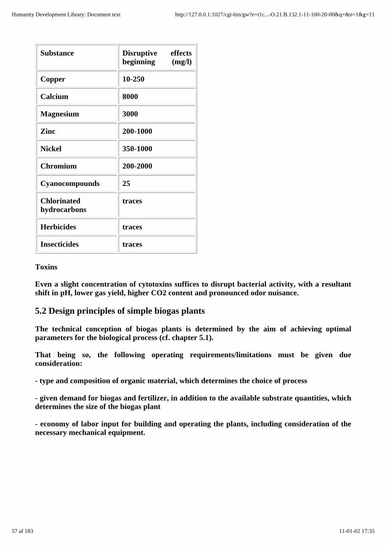
Substance Disruptive effectsbeginning (mg/l)
Copper 10-250
Calcium 8000
Magnesium 3000
Zinc 200-1000
Nickel 350-1000
Chromium 200-2000
Cyanocompounds 25
Chlorinatedhydrocarbons
traces
Herbicides traces
Insecticides traces
Toxins
Even a slight concentration of cytotoxins suffices to disrupt bacterial activity, with a resultantshift in pH, lower gas yield, higher CO2 content and pronounced odor nuisance.
5.2 Design principles of simple biogas plants
The technical conception of biogas plants is determined by the aim of achieving optimalparameters for the biological process (cf. chapter 5.1).
That being so, the following operating requirements/limitations must be given dueconsideration:
- type and composition of organic material, which determines the choice of process
- given demand for biogas and fertilizer, in addition to the available substrate quantities, whichdetermines the size of the biogas plant
- economy of labor input for building and operating the plants, including consideration of thenecessary mechanical equipment.
57 af 183 11-01-02 17:35
Humanity Development Library: Document text http://127.0.0.1:1027/cgi-bin/gw?e=t1c...-O.21.B.132.1-11-100-20-00&q=&n=1&g=11

Fig. 5.3: The batch-feed principle (1) vs the continuous feed principle (2) (Source: OEKOTOP)
Fig. 5.4: The fermentation channel (1) vs the complete-mixed digester (2) (Source: OEKOTOP)
58 af 183 11-01-02 17:35
Humanity Development Library: Document text http://127.0.0.1:1027/cgi-bin/gw?e=t1c...-O.21.B.132.1-11-100-20-00&q=&n=1&g=11

Fig. 5.5: Slurry flow for various configuration of feed, discharge and stirring. 1 Low inlet,outlet at top (beside the gasholder); 2 High inlet, low outlet (normal); 3 Low inlet, low outlet(with partition wall); 4 Vertical agitator; 5 Fixed-dome plant; F: Quality factor for thoroughmixing and favorable throughflow conditions, normal situation = 100% (Source: OEKOTOP)
The range of simple biogas plants includes the following basic types:
Batch-type plants are thus referred to because they are charged with successive batches oforganic material and a certain amount of seeding slurry to serve as starter. The digestionprocess is interrupted as soon as the rate of biogas production has slowed down to the pointthat continued digestion would be uneconomical. Then, the plant is cleaned out and refilled. Toachieve a more or less uniform rate of biogas production, several digesters must be operated inparallel, i.e. filled at staggered intervals. Differentiation is made between semi-dry plants(operating on a total-solids content of more than 15%) and liquid plants.
Batch plants are suitable for digesting strawy, fibrous material with a high solids content,usually in areas with low annual precipitation, and for use as simple demonstration plants.
Continuous-feed plants are those in which there is a continuous throughflow of biomass,resulting in a near-constant volume of slurry in the digester. In practice, such plants are fedonce or twice each day. There are three main sub-versions:
- complete-mixed digesters
- fermentation channels and
- combinations of the two.
The advantage of continuous-feed plants is that the bacteria receive a regular supply ofsubstrate and are therefore able to generate a more constant supply of biogas. The problem isthat buoyant constituents tend to form a stiff layer of scum that impedes biogas production andmay even plug up the plant. That drawback can be countered by installing suitable agitatorsand lengthening the retention time.
The digester inlet, outlet and, to the extent applicable, the agitator must be designed to worktogether in ensuring the proper retention time, i.e. to avoid short-circuit flow, because the gasproduction rate would otherwise stay well below the optimum level.
Continuous-feed biogas plants are sized on the basis of the desired retention time for theorganic material, in combination with the digester load, which in turn is a function of theprevailing temperature and type of substrate (cf. chapter 4.3).
5.3 Biogas plants of simple design
5.3.1 Floating-drum plants
5.3.2 Fixed-dome plants
5.3.3 Other types of construction
There are two basic types of tested biogas plants that have gained widespread acceptance inagricultural practice:
- floating-drum plants in which the metal gasholder floats on the digester, and
59 af 183 11-01-02 17:35
Humanity Development Library: Document text http://127.0.0.1:1027/cgi-bin/gw?e=t1c...-O.21.B.132.1-11-100-20-00&q=&n=1&g=11

- fixed-dome plants in which gas storage is effected according to the displacement principle.
5.3.1 Floating-drum plants
A floating-drum biogas plant essentially consists of a cylindrical or dome-shaped digester and amovable, floating gasholder, or drum. The drum in which the biogas collects has an internal orexternal guide frame that provides stability and keeps the drum upright. Braces can be weldedinto the drum as a means of breaking up the scum layer when the drum is rotated. The digesteris usually made of brick, concrete or quarrystone masonry with rendering, while the gasholderis normally made of metal.
Floating-drum plants are used chiefly for digesting animal and human excrements on acontinuous-feed mode of operation, i.e. with daily input. They are used most frequently by:
- small-to-midsize family farms (digester size: 5 - 15 m³)
- institutions and large agroindustrial estates (digester size: 20-100 m³).
Advantages: Floating-drum plants are easy to understand and operate. They provide gas at aconstant pressure, and the stored volume is immediately recognizable.
Drawbacks: The steel drum is relatively expensive and maintenance-intensive due to thenecessity of periodic painting and rust removal. If fibrous substrates are used, the gasholdershows a tendency to get "stuck" in the resultant floating scum.
Floating-drum plants can be recommended as a mature, easy-to-operate, functionally capablemeans of producing biogas, particularly when reliability is deemed more important thaninexpensiveness.
Floating-drum plants with gasholder in the digester (cf. fig. 5.6)
The dome shape is inherently sturdy, compact and material-sparing. The digester is easy tobuild, and the techniques can be learned by local craftsmen in a short time (cf. fig. 5.21).
Water-jacket plant (cf. fig. 5.7)
Water-jacket biogas plants are characterized by a long useful life and a more aestheticappearance (no dirty gasholder). Due to their superior hygiene, they are recommended for usein the fermentation of night soil and for cases involving pronounced scumming, e.g. due torapid evaporation, since the gasholder cannot get stuck in the scum. The extra cost of themasonry water jacket is relatively modest.
Cylindrical plant for quarrystone masonry and concrete (cf. fig. 5.8)
It is anything but easy to make a dome-shaped digester out of quarrystone masonry; it is mucheasier to build a concrete cylinder. In such cases, the classical (Indian) version with acylindrical digester is quite practical Note: Quarrystone masonry consumes a lot of mortar.
60 af 183 11-01-02 17:35
Humanity Development Library: Document text http://127.0.0.1:1027/cgi-bin/gw?e=t1c...-O.21.B.132.1-11-100-20-00&q=&n=1&g=11

Fig. 5.6: Floating-drum plant with internal guide frame. 1 Mixing pit, 11 Fill pipe, 2 Digester, 3Gasholder, 31 Guide frame, 4 Slurry store, 41 Discharge pipe, 5 Gas pipe, 51 Water trap(Source: Sasse 1984)
Fig. 5.7: Water-jacket plant with external guide frame. 1 Mixing pit, 11 Fill pipe, 2 Digester, 3Gasholder, 31 Guide frame, 4 Slurry store, 5 Gas pipe (Source: Sasse 1984)
61 af 183 11-01-02 17:35
Humanity Development Library: Document text http://127.0.0.1:1027/cgi-bin/gw?e=t1c...-O.21.B.132.1-11-100-20-00&q=&n=1&g=11
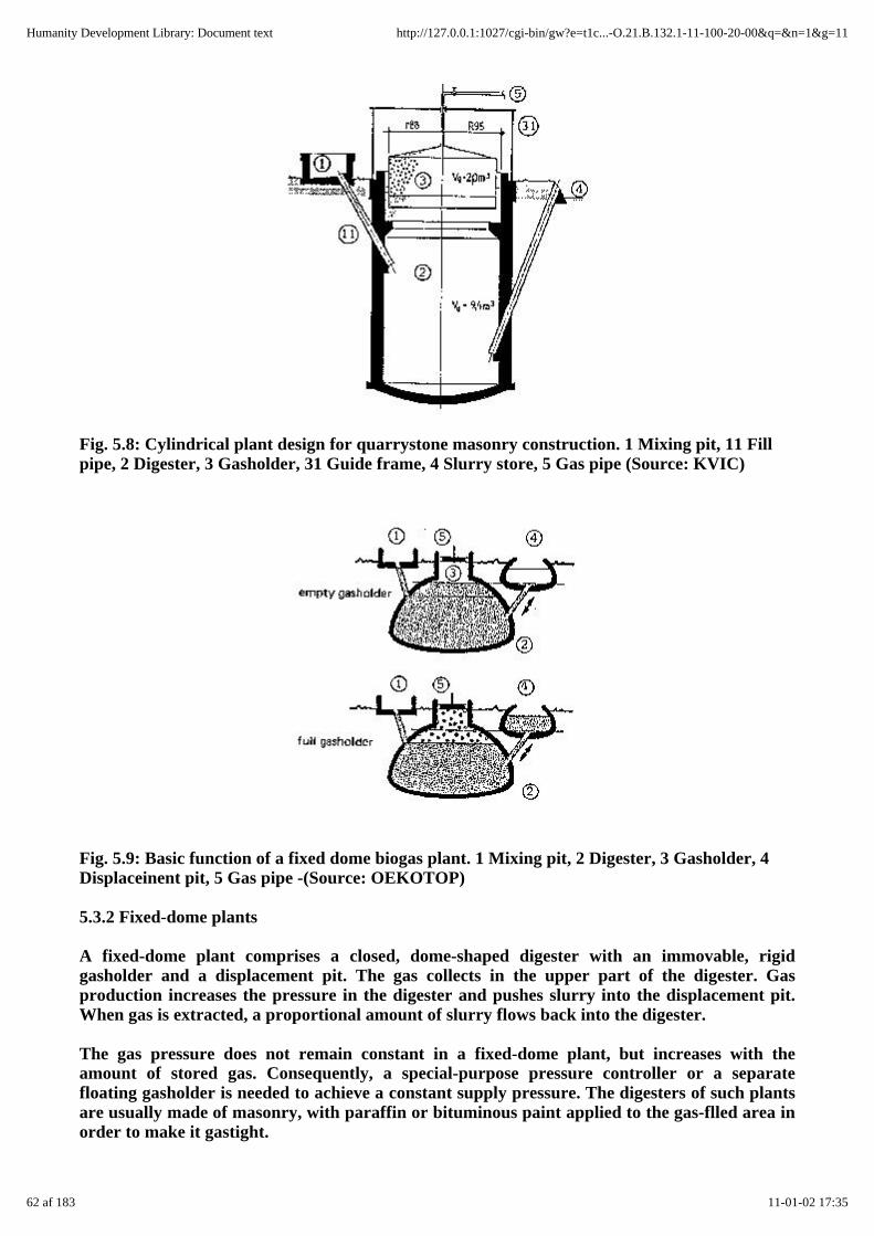
Fig. 5.8: Cylindrical plant design for quarrystone masonry construction. 1 Mixing pit, 11 Fillpipe, 2 Digester, 3 Gasholder, 31 Guide frame, 4 Slurry store, 5 Gas pipe (Source: KVIC)
Fig. 5.9: Basic function of a fixed dome biogas plant. 1 Mixing pit, 2 Digester, 3 Gasholder, 4Displaceinent pit, 5 Gas pipe -(Source: OEKOTOP)
5.3.2 Fixed-dome plants
A fixed-dome plant comprises a closed, dome-shaped digester with an immovable, rigidgasholder and a displacement pit. The gas collects in the upper part of the digester. Gasproduction increases the pressure in the digester and pushes slurry into the displacement pit.When gas is extracted, a proportional amount of slurry flows back into the digester.
The gas pressure does not remain constant in a fixed-dome plant, but increases with theamount of stored gas. Consequently, a special-purpose pressure controller or a separatefloating gasholder is needed to achieve a constant supply pressure. The digesters of such plantsare usually made of masonry, with paraffin or bituminous paint applied to the gas-flled area inorder to make it gastight.
62 af 183 11-01-02 17:35
Humanity Development Library: Document text http://127.0.0.1:1027/cgi-bin/gw?e=t1c...-O.21.B.132.1-11-100-20-00&q=&n=1&g=11

Fixed-dome plants can handle fibrous substances in combination with animal excrements, sincethe motion of the substrate breaks up the scum each day. The plant is a continous-feed type, butcan accept several days' worth of substrate at a time, if the displacement pit is large enough.
Fixed-dome plants must be covered with earth up to the top of the gas-filled space as aprecautionary measure (internal pressure up to 0.1-0.15 bar). As a rule, the size of the digesterdoes not go beyond 20 m³, corresponding to a gasholder volume of 3-4 m³. The earth covermakes them suitable for colder climates, and they can be heated as necessary.
Advantages: Fixed-dome plants are characterized by low initial cost and a long useful life, sinceno moving or rusting parts are involved. The basic design is compact and well-insulated.
Drawbacks: Masonry is not normally gaslight (porosity and cracks) and therefore requires theuse of special sealants. Cracking often causes irreparable leaks. Fluctuating gas pressurecomplicates gas utilization, and plant operation is not readily understandable.
Fixed-dome plants are only recommended in cases where experienced biogas technicians areavailable for building them, and when the user is amply familiar with how the plant operates.
Fixed-dome plant with central entry hatch (cf. fig. 5.10)
The digester has the form of a hemispherical dome which is easy to build. Floating scum can beremoved from the full digester through the central entry hatch.
Fixed-dome plant with suspended dome (cf. fig. 5.11)
Providing a separate foundation for the gas dome yields a statically advantageous,material-saving configuration that is very well suited for fixed-dome plants of ample size. Thedome's foundation helps prevent cracking due to tensile stress, and the digesting space is madeless expensive, since it can be built of thinner masonry, ferrocement rendering or - in the case ofimpervious soil - even left unlined.
Fig. 5.10: Fixed-dome plant with central entry hatch. 1 Mixing pit, 11 Fill pipe, 2 Digester, 3Gas holder, 31 Entry hatch, 32 Gas cover, 33 Seal coating, 34 Rated break ring, 4 Displacementpit, 41 Outlet pipe, 42 Overflow, 43 Cover, 5 Gas pipe, 51 Water trap, 52 Cover (Source: Sasse1984 / BEP Tanzania 1987 / OEKOTOP)
63 af 183 11-01-02 17:35
Humanity Development Library: Document text http://127.0.0.1:1027/cgi-bin/gw?e=t1c...-O.21.B.132.1-11-100-20-00&q=&n=1&g=11
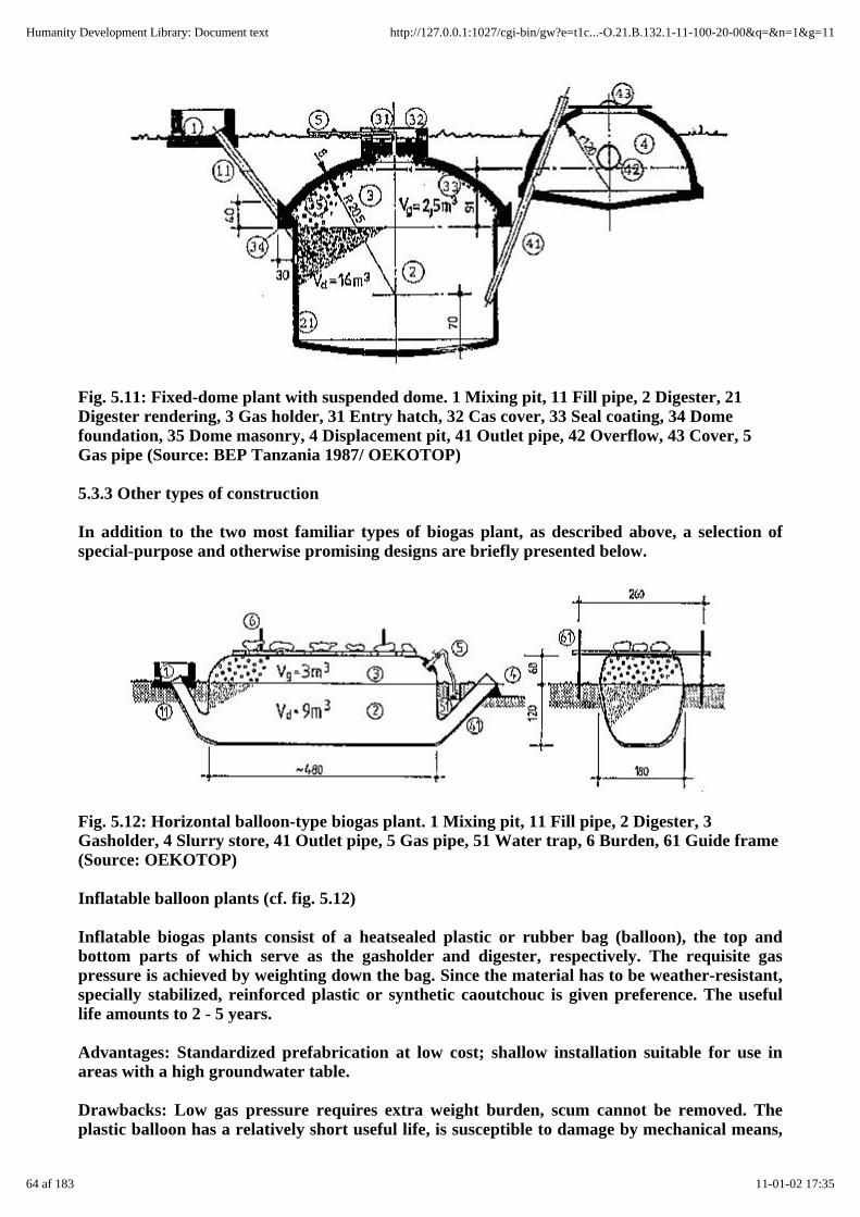
Fig. 5.11: Fixed-dome plant with suspended dome. 1 Mixing pit, 11 Fill pipe, 2 Digester, 21Digester rendering, 3 Gas holder, 31 Entry hatch, 32 Cas cover, 33 Seal coating, 34 Domefoundation, 35 Dome masonry, 4 Displacement pit, 41 Outlet pipe, 42 Overflow, 43 Cover, 5Gas pipe (Source: BEP Tanzania 1987/ OEKOTOP)
5.3.3 Other types of construction
In addition to the two most familiar types of biogas plant, as described above, a selection ofspecial-purpose and otherwise promising designs are briefly presented below.
Fig. 5.12: Horizontal balloon-type biogas plant. 1 Mixing pit, 11 Fill pipe, 2 Digester, 3Gasholder, 4 Slurry store, 41 Outlet pipe, 5 Gas pipe, 51 Water trap, 6 Burden, 61 Guide frame(Source: OEKOTOP)
Inflatable balloon plants (cf. fig. 5.12)
Inflatable biogas plants consist of a heatsealed plastic or rubber bag (balloon), the top andbottom parts of which serve as the gasholder and digester, respectively. The requisite gaspressure is achieved by weighting down the bag. Since the material has to be weather-resistant,specially stabilized, reinforced plastic or synthetic caoutchouc is given preference. The usefullife amounts to 2 - 5 years.
Advantages: Standardized prefabrication at low cost; shallow installation suitable for use inareas with a high groundwater table.
Drawbacks: Low gas pressure requires extra weight burden, scum cannot be removed. Theplastic balloon has a relatively short useful life, is susceptible to damage by mechanical means,
64 af 183 11-01-02 17:35
Humanity Development Library: Document text http://127.0.0.1:1027/cgi-bin/gw?e=t1c...-O.21.B.132.1-11-100-20-00&q=&n=1&g=11

and usually not available locally. In addition, local craftsmen are rarely in a position to repair adamaged balloon.
Inflatable biogas plants are recommended, if local repair is or can be made possible and thecost advantage is substantial.
Fig. 5.13: Earth-pit plant with plastic-sheet gasholder. 1 Mixing pit, ll Fill pipe, 2 Digester, 21Rendering, 22 Peripheral masonry, 3 Plastic-sheet gasholder, 31 Cuide frame, 32 Woodenframe, 33 Weight, 34 Frame anchorage, 35 Plastic sheeting, 4 Slurry store, 41 Overflow, 5 Gaspipe (Source: OEKOTOP)
Earth-pit plants (cf. fig. 5.13)
Masonry digesters are not necessary in stable soil (e.g. Iaterite). It is sufficient to line the pitwith a thin layer of cement (netting wire fixed to the pit wall and rendered) in order to preventseepage. The edge of the pit is reinforced with a ring of masonry that also serves as anchoragefor the gasholder. The gasholder can be made of metal or plastic sheeting. If plastic sheeting isused, it must be attached to a quadratic wooden frame that extends down into the slurry and isanchored in place to counter its buoyancy. The requisite gas pressure is achieved by placingweights on the gasholder. An overflow point in the peripheral wall serves as the slurry outlet.
Advantages: Low cost of installation (as little as 1/5th as much as a floating-drum plant),including high potential for self help.
Drawbacks: Short useful life, serviceable only in suitable, impermeable types of soil.
Earth-pit plants can only be recommended for installation in impermeable soil located abovethe groundwater table. Their construction is particularly inexpensive in connection with plasticsheet gasholders.
65 af 183 11-01-02 17:35
Humanity Development Library: Document text http://127.0.0.1:1027/cgi-bin/gw?e=t1c...-O.21.B.132.1-11-100-20-00&q=&n=1&g=11
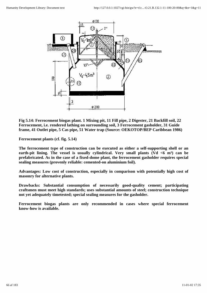
Fig 5.14: Ferrocement biogas plant. 1 Mixing pit, 11 Fill pipe, 2 Digester, 21 Backfill soil, 22Ferrocement, i.e. rendered lathing on surrounding soil, 3 Ferrocement gasholder, 31 Guideframe, 41 Outlet pipe, 5 Cas pipe, 51 Water trap (Source: OEKOTOP/BEP Caribbean 1986)
Ferrocement plants (cf. fig. 5.14)
The ferrocement type of construction can be executed as either a self-supporting shell or anearth-pit lining. The vessel is usually cylindrical. Very small plants (Vd <6 m³) can beprefabricated. As in the case of a fixed-dome plant, the ferrocement gasholder requires specialsealing measures (provenly reliable: cemented-on aluminium foil).
Advantages: Low cost of construction, especially in comparison with potentially high cost ofmasonry for alternative plants.
Drawbacks: Substantial consumption of necessarily good-quality cement; participatingcraftsmen must meet high standards; uses substantial amounts of steel; construction techniquenot yet adequately timetested; special sealing measures for the gasholder.
Ferrocement biogas plants are only recommended in cases where special ferrocementknow-how is available.
66 af 183 11-01-02 17:35
Humanity Development Library: Document text http://127.0.0.1:1027/cgi-bin/gw?e=t1c...-O.21.B.132.1-11-100-20-00&q=&n=1&g=11

Fig. 5.15: Horizontal biogas plant (KVIC shallow design). 1 Mixing pit, 11 Fill pipe, 2 Digester,3 Gasholder, 31 Guide frame, 4 Slurry store, 41 Outlet pipe, 5 Gas pipe, 51 Water trap (Source:OEKOTOP / KVIC 1978)
Horizontal plants (cf. fig. 5.15)
Horizontal biogas plants are usually chosen when shallow installation is called for(groundwater, rock). They are made of masonry or concrete.
Advantages: Shallow construction despite large slurry space.
Drawbacks: Problems with gas-space leakage, difficult elimination of scum.
Plants with separate gasholders
Masonry dome plants are sometimes equipped with separate gasholders. That approach alwaysinvolves substantial extra cost and therefore is rarely recommended. Plants with separategasholders are justifiable, when the points of gas consumption are a considerable distance awayfrom the digester (at least 1 00 m).
Altematively, a separate gasholder could be useful for restoring the utility value of, say, afixed-dome plant that has been found to leak at an elevated pressure level.
Table 5.7: Comparison of various plant designs (Source: OEKOTOP)
Design: Criteria:
Floating-drum Water-jacket Fixed dome
Design principle continuous-feed, mixeddigester
continuous-feed, mixeddigester
continuous-feed,digester
Main componentsdigester/gasholder
masonry digester,floating metal gasholder
masonry digester,floating metal gasholderin sep. water jacket
masonrydisplacement
Preferred substrates animal excrements, withor without vegetablewaste
animal excrements withor without vegetablewaste
animalvegetable
67 af 183 11-01-02 17:35
Humanity Development Library: Document text http://127.0.0.1:1027/cgi-bin/gw?e=t1c...-O.21.B.132.1-11-100-20-00&q=&n=1&g=11

Anticipated useful life 8-12 years 10-15 years 12-20 years
Digester volume (Vd) 6-100 m³ 6-100 m³ 6-20 m³
Suitability:
- advantages easy construction andoperation, uniform gaspressure, maturetechnology
very reliable, easyconstruction andoperation, uniform gaspressure, long useful life,mature technology
low costlong usefulsulated
- drawbacks metal gasholder can rust expensive sealing oftuating
- All biogas plants require careful, regular inspection/monitoring of their gas-containing
Operation andmaintenance
simple and easy; regularpainting of metal gas-holder
simple and easy; regularpainting of metal gas-holder
easy afterfamiliarization
Daily gas-output 0.3-0.6 0.3-0.6 0.2-0.5
(m³ gas/m³ Vd)
(depends on substrate composition; here: cattle dung)
Cost elements metal gasholder, digester metal gasholder, digester combinedgasholder,
Comparison factor 100 120 60-90
Recommended uses fully developed, reliablefamily size system
like floating-drum, pluslonger useful life andoperational reliability(incl. operation withnight soil)
inexpensivegood forextensiveexperience
Suitability fordissemination
+ ++ +
++ highly recommended, + recommended with certain
balloon-type Earth pit Ferrocement Horizontal
continuous-feed,fermentation channel
continuous-feed, mixeddigester
continuous-feed, mixeddigester
continuous-ffeed,fermentation
integrated digester/gas-holder made of plasticsheeting
earth pit as digester,plastic gasholder
ferrocement digester,gasholder made of metalor ferrocement
masonryfloating(or separate)
animal excrements only animal excrements only animal excrements, withor without vegetable
animal excrements,or without
68 af 183 11-01-02 17:35
Humanity Development Library: Document text http://127.0.0.1:1027/cgi-bin/gw?e=t1c...-O.21.B.132.1-11-100-20-00&q=&n=1&g=11
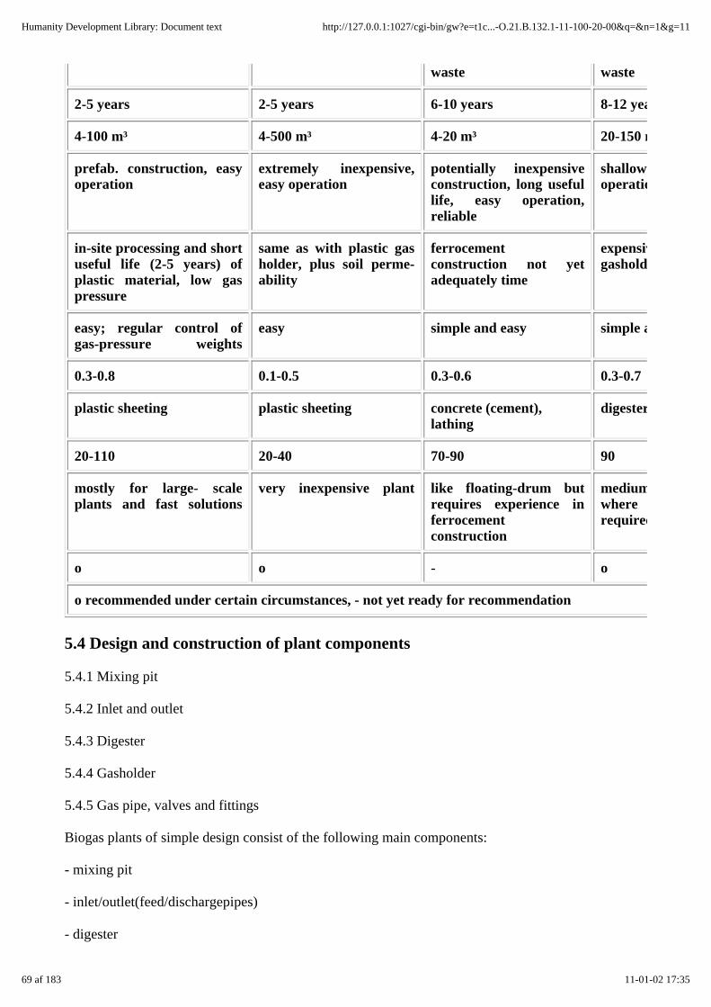
waste waste
2-5 years 2-5 years 6-10 years 8-12 years
4-100 m³ 4-500 m³ 4-20 m³ 20-150 m³
prefab. construction, easyoperation
extremely inexpensive,easy operation
potentially inexpensiveconstruction, long usefullife, easy operation,reliable
shallowness,operation
in-site processing and shortuseful life (2-5 years) ofplastic material, low gaspressure
same as with plastic gasholder, plus soil perme-ability
ferrocementconstruction not yetadequately time
expensive,gasholder
easy; regular control ofgas-pressure weights
easy simple and easy simple and
0.3-0.8 0.1-0.5 0.3-0.6 0.3-0.7
plastic sheeting plastic sheeting concrete (cement),lathing
digester,
20-110 20-40 70-90 90
mostly for large- scaleplants and fast solutions
very inexpensive plant like floating-drum butrequires experience inferrocementconstruction
medium-sizewhererequired
o o - o
o recommended under certain circumstances, - not yet ready for recommendation
5.4 Design and construction of plant components
5.4.1 Mixing pit
5.4.2 Inlet and outlet
5.4.3 Digester
5.4.4 Gasholder
5.4.5 Gas pipe, valves and fittings
Biogas plants of simple design consist of the following main components:
- mixing pit
- inlet/outlet(feed/dischargepipes)
- digester
69 af 183 11-01-02 17:35
Humanity Development Library: Document text http://127.0.0.1:1027/cgi-bin/gw?e=t1c...-O.21.B.132.1-11-100-20-00&q=&n=1&g=11
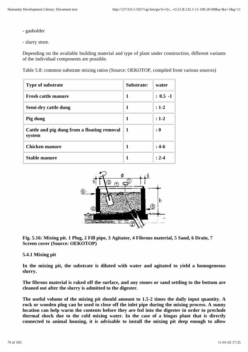
- gasholder
- slurry store.
Depending on the available building material and type of plant under construction, different variantsof the individual components are possible.
Table 5.8: common substrate mixing ratios (Source: OEKOTOP, compiled from various sources)
Type of substrate Substrate: water
Fresh cattle manure 1 : 0.5 -1
Semi-dry cattle dung 1 : 1-2
Pig dung 1 : 1-2
Cattle and pig dung from a floating removalsystem
1 : 0
Chicken manure 1 : 4-6
Stable manure 1 : 2-4
Fig. 5.16: Mixing pit. 1 Plug, 2 Fill pipe, 3 Agitator, 4 Fibrous material, 5 Sand, 6 Drain, 7Screen cover (Source: OEKOTOP)
5.4.1 Mixing pit
In the mixing pit, the substrate is diluted with water and agitated to yield a homogeneousslurry.
The fibrous material is raked off the surface, and any stones or sand settling to the bottom arecleaned out after the slurry is admitted to the digester.
The useful volume of the mixing pit should amount to 1.5-2 times the daily input quantity. Arock or wooden plug can be used to close off the inlet pipe during the mixing process. A sunnylocation can help warm the contents before they are fed into the digester in order to precludethermal shock due to the cold mixing water. In the case of a biogas plant that is directlyconnected to animal housing, it is advisable to install the mixing pit deep enough to allow
70 af 183 11-01-02 17:35
Humanity Development Library: Document text http://127.0.0.1:1027/cgi-bin/gw?e=t1c...-O.21.B.132.1-11-100-20-00&q=&n=1&g=11

installation of a floating gutter leading directly into the pit. Care must also be taken to ensurethat the low position of the mixing pit does not result in premature digestion and resultantslurry formation. For reasons of hygiene, toilets should have a direct connection to the inletpipe.
Fig. 5.17: Mixing pit, gutter and toilet drain pipe. 1 Barn, 2 Toilet, 3 Biogas plant, 4 Feed gutter2% gradient), 5 Mixing pit (Source: OEKOTOP)
5.4.2 Inlet and outlet
The inlet (feed) and outlet (discharge) pipes lead straight into the digester at a steep angle. Forliquid substrate, the pipe diameter should be 10-15 cm, while fibrous substrate requires adiameter of 20 - 30 cm. Plastic or concrete pipes are preferred.
Note:
- Both the inlet pipe and the outlet pipe must be freely accessible and straight, so that a rod canbe pushed through to eliminate obstructions and agitate the digester contents;
- The pipes should penetrate the digester wall at a point below the slurry level. The points ofpenetration should be sealed off and reinforced with mortar.
- The inlet pipe ends higher than the outlet pipe in the digester in order to promote moreuniform throughflow. In a fixed-dome plant, the inlet pipe defines the bottom limit of thegasholder, thus providing overpressure relief.
- In a floating-drum plant, the end of the outlet pipe determines the digester's slurry level.
Fig. 5.18: Inlet and outlet for fixed-dome (1) and floating-drum plants (2) (Source: OEKOTOP)
71 af 183 11-01-02 17:35
Humanity Development Library: Document text http://127.0.0.1:1027/cgi-bin/gw?e=t1c...-O.21.B.132.1-11-100-20-00&q=&n=1&g=11

Fig. 5.19: Forces acting on a spherical-dome digester (Source: OEKOTOP)
5.4.3 Digester
Design
The digester of a biogas plant must accommodate the substrate and bacterial activity, as well asfulfill the following structural functions:
- accept the given static forces
- provide impermeability to gas and liquids
- be durable and resistant to corrosion
As a rule, the digesters of simple biogas plants are made of masonry or concrete. Such materialsare adequately pressure-resistant, but also susceptible to cracking as a result of tensile forces.
The following forces act on the digester:
- external active earth pressures (pE), causing compressive forces within the masonry
- internal hydrostatic and gas pressures (pW), causing tensile stress in the masonry.
Fig. 5.20: Level line, excavation and foundation. 1 Workspace, 2 Inclination of conicalfoundation, 3 Sloping excavation, 4 Vertical excavation, 51 Quarrystone foundation, 52 Brickfoundation, 6 Packing sand, 7 Mortar screed, 8 Foot reinforcement for fixed-dome plant, 9Level line (Source: OEKOTOP / Sasse 1984)
Thus, the external pressure applied by the surrounding earth must be greater at all points thanthe internal forces (pE > pW). For the procedure on how to estimate earth force andhydrostatic forces, please refer to chapter 10.1.4.
Round and spherical shapes are able to accept the highest forces—and do it uniformly. Edges
72 af 183 11-01-02 17:35
Humanity Development Library: Document text http://127.0.0.1:1027/cgi-bin/gw?e=t1c...-O.21.B.132.1-11-100-20-00&q=&n=1&g=11
and corners lead to peak stresses and, possibly, to tensile stresses and cracking. Such basicconsiderations suggest the use of familiar cylindrical and dome designs allowing:
- inexpensive, material-sparing construction based on modest material thicknesses
- a good volume/surface ratio and
- better (read: safe) stability despite simple construction.
The dome foundation has to contend with the highest loads. Cracks occurring around thefoundation can spread out over the entire dome, but are only considered dangerous in the caseof fixed-dome plants. A rated break ring can be provided to limit cracking.
Groundwork
The first step of building the plant consists of defining the plant level line with a taut string. Allimportant heights and depths are referred to that line.
Excavation
The pit for the biogas plant is excavated by hand in the shape of a cylindrical shaft. The shaftdiameter should be approx. 2 x 50 cm larger than that of the digester. If the soil is adequatelycompact and adhesive, the shaft wall can be vertical. Otherwise it will have to be inclined. Theoverburden, if reusable, is stored at the side and used for backfilling and compacting aroundthe finished plant.
Foundation
The foundation slab must be installed on well-smoothed ground that is stable enough tominimize settling. Any muddy or loose subsoil (fill) must be removed and replaced by sand orstones. The bottom must have the shape of a shallow inverted dome to make it more stable andrigid than a flat slab. Quarrystones, bricks and mortar or concrete can be used as constructionmaterials. Steel reinforcing rods are only necessary for large plants, and then only in the formof peripheral ties below the most heavily burdened part, i.e. the dome foundation.
73 af 183 11-01-02 17:35
Humanity Development Library: Document text http://127.0.0.1:1027/cgi-bin/gw?e=t1c...-O.21.B.132.1-11-100-20-00&q=&n=1&g=11

Fig. 5.21: Construction of a spherical dome from masonry. 1 Dome/masonry, 2 Establishing thecenterpoint, 3 Trammel, 4 Brick clamp with counterweights, 5 Backfill (Source: Sasse 1984)
Dome
The dome of the biogas plant is hemispherical with a constant radius. Consequently, themasonry work is just as simple as for a cylinder and requires no falsework. The only accessorytool needed is a trammel.
The dome masonry work consists of the following steps:
- finding and fixing the centerpoint of the dome radius in relation to the level line
- layer-by-layer setting of the dome masonry, with the bricks set in mortar, positioned andaligned with the aid of the trammel and tapped for proper seating
- in the upper part of the dome - when the trammel is standing at a steeper angle than 45°, thebricks must be held in place until each course is complete. Sticks or clamps with counterweightscan be used to immobilize them.
Each closed course is inherently stable and therefore need not be held in place any longer. Themortar should be sufficiently adhesive, i.e. it should be made of finely sieved sand mixed withan adequate amount of cement.
Table 5.9: Mortar mixing ratios (Source: Sasse, 1984)
74 af 183 11-01-02 17:35
Humanity Development Library: Document text http://127.0.0.1:1027/cgi-bin/gw?e=t1c...-O.21.B.132.1-11-100-20-00&q=&n=1&g=11
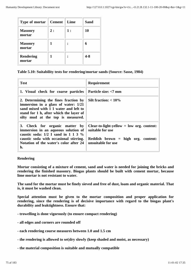
Type of mortar Cement Lime Sand
Masonrymortar
2 : 1 : 10
Masonrymortar
1 : 6
Renderingmortar
1 : 4-8
Table 5.10: Suitability tests for rendering/mortar sands (Source: Sasse, 1984)
Test Requirement
1. Visual check for coarse particles Particle size: <7 mm
2. Determining the fines fraction byimmersion in a glass of water: 1/21sand mixed with 1 1 water and left tostand for 1 h, after which the layer ofsilty mud at the top is measured.
Silt fraction: < 10%
3. Check for organic matter byimmersion in an aqueous solution ofcaustic soda: 1/2 I sand in 1 1 3 %caustic soda with occasional stirring.Notation of the water's color after 24h.
Clear-to-light-yellow = low org. content:suitable for use
Reddish brown = high org. content:unsuitable for use
Rendering
Mortar consisting of a mixture of cement, sand and water is needed for joining the bricks andrendering the finished masonry. Biogas plants should be built with cement mortar, becauselime mortar is not resistant to water.
The sand for the mortar must be finely sieved and free of dust, loam and organic material. Thatis, it must be washed clean.
Special attention must be given to the mortar composition and proper application forrendering, since the rendering is of decisive importance with regard to the biogas plant'sdurability and leaktightness. Ensure that:
- trowelling is done vigorously (to ensure compact rendering)
- all edges and corners are rounded off
- each rendering course measures between 1.0 and 1.5 cm
- the rendering is allowed to set|dry slowly (keep shaded and moist, as necessary)
- the material composition is suitable and mutually compatible
75 af 183 11-01-02 17:35
Humanity Development Library: Document text http://127.0.0.1:1027/cgi-bin/gw?e=t1c...-O.21.B.132.1-11-100-20-00&q=&n=1&g=11
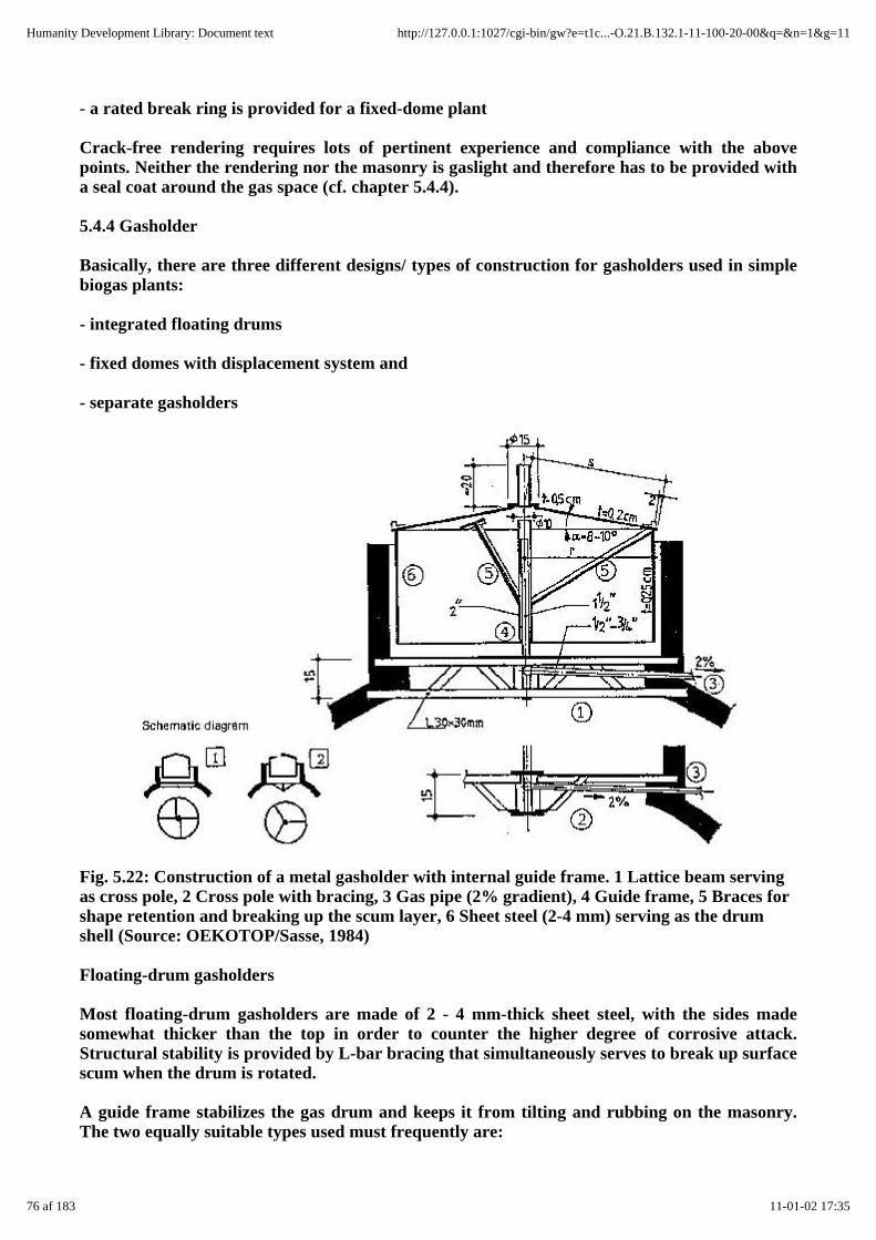
- a rated break ring is provided for a fixed-dome plant
Crack-free rendering requires lots of pertinent experience and compliance with the abovepoints. Neither the rendering nor the masonry is gaslight and therefore has to be provided witha seal coat around the gas space (cf. chapter 5.4.4).
5.4.4 Gasholder
Basically, there are three different designs/ types of construction for gasholders used in simplebiogas plants:
- integrated floating drums
- fixed domes with displacement system and
- separate gasholders
Fig. 5.22: Construction of a metal gasholder with internal guide frame. 1 Lattice beam servingas cross pole, 2 Cross pole with bracing, 3 Gas pipe (2% gradient), 4 Guide frame, 5 Braces forshape retention and breaking up the scum layer, 6 Sheet steel (2-4 mm) serving as the drumshell (Source: OEKOTOP/Sasse, 1984)
Floating-drum gasholders
Most floating-drum gasholders are made of 2 - 4 mm-thick sheet steel, with the sides madesomewhat thicker than the top in order to counter the higher degree of corrosive attack.Structural stability is provided by L-bar bracing that simultaneously serves to break up surfacescum when the drum is rotated.
A guide frame stabilizes the gas drum and keeps it from tilting and rubbing on the masonry.The two equally suitable types used must frequently are:
76 af 183 11-01-02 17:35
Humanity Development Library: Document text http://127.0.0.1:1027/cgi-bin/gw?e=t1c...-O.21.B.132.1-11-100-20-00&q=&n=1&g=11
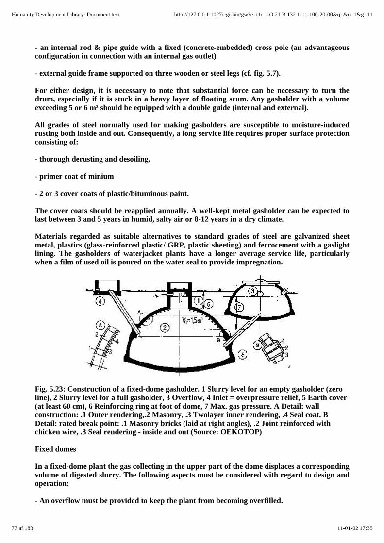
- an internal rod & pipe guide with a fixed (concrete-embedded) cross pole (an advantageousconfiguration in connection with an internal gas outlet)
- external guide frame supported on three wooden or steel legs (cf. fig. 5.7).
For either design, it is necessary to note that substantial force can be necessary to turn thedrum, especially if it is stuck in a heavy layer of floating scum. Any gasholder with a volumeexceeding 5 or 6 m³ should be equipped with a double guide (internal and external).
All grades of steel normally used for making gasholders are susceptible to moisture-inducedrusting both inside and out. Consequently, a long service life requires proper surface protectionconsisting of:
- thorough derusting and desoiling.
- primer coat of minium
- 2 or 3 cover coats of plastic/bituminous paint.
The cover coats should be reapplied annually. A well-kept metal gasholder can be expected tolast between 3 and 5 years in humid, salty air or 8-12 years in a dry climate.
Materials regarded as suitable alternatives to standard grades of steel are galvanized sheetmetal, plastics (glass-reinforced plastic/ GRP, plastic sheeting) and ferrocement with a gaslightlining. The gasholders of waterjacket plants have a longer average service life, particularlywhen a film of used oil is poured on the water seal to provide impregnation.
Fig. 5.23: Construction of a fixed-dome gasholder. 1 Slurry level for an empty gasholder (zeroline), 2 Slurry level for a full gasholder, 3 Overflow, 4 Inlet = overpressure relief, 5 Earth cover(at least 60 cm), 6 Reinforcing ring at foot of dome, 7 Max. gas pressure. A Detail: wallconstruction: .1 Outer rendering,.2 Masonry, .3 Twolayer inner rendering, .4 Seal coat. BDetail: rated break point: .1 Masonry bricks (laid at right angles), .2 Joint reinforced withchicken wire, .3 Seal rendering - inside and out (Source: OEKOTOP)
Fixed domes
In a fixed-dome plant the gas collecting in the upper part of the dome displaces a correspondingvolume of digested slurry. The following aspects must be considered with regard to design andoperation:
- An overflow must be provided to keep the plant from becoming overfilled.
77 af 183 11-01-02 17:35
Humanity Development Library: Document text http://127.0.0.1:1027/cgi-bin/gw?e=t1c...-O.21.B.132.1-11-100-20-00&q=&n=1&g=11

- The gas outlet must be located about 10 cm higher than the overflow in order to keep the pipefrom plugging up.
- A gas pressure of 1 mWG or more can develop in the gas space, Consequently, the plant mustbe covered with enough earth to provide an adequate counterpressure; special care must betaken to properly secure the entry hatch, which may require weighing it down with 100 kg ormore.
The following structural measures are recommended for avoiding or at least limiting theoccurrence of cracks in the dome (cf. fig. 5.23):
- For reasons of static stability, the centerpoint of the dome radius should be lowered by 0.25 R(corresponding to bottom center of the foundation). This changes the geometry of the digester,turning it into a spherical segment, i.e. flatter and wider, which can be of advantage for theplant as a whole.
- The foot of the dome should be made more stable and secure by letting the foundation slabproject out enough to accept an outer ring of mortar.
- A rated break/pivot ring should be provided at a point located between 1/2 and 2/3 of theminimum slurry level. This in order to limit the occurrence or propagation of cracks in thevicinity of the dome foot and to displace forces through its stiffening/ articulating effect suchthat tensile forces are reduced around the gas space.
Fig. 5.24: Entry hatch of a fixed-dome biogas plant. 1 Concrete cover, 2 Gas pipe, 21 Flexibleconnection (hose), 3 Cover wedging, 31 Length of pipe anchored in the masonry, 32 Retainingrod, 33 Wooden/metal wedges, 4 Edge seal made of loam/mastic compound, 5 Handles, 6Weights, 7 Water (Source: OEKOTOP)
In principle, however, masonry, mortar and concrete are not gaslight, with or without mortaradditives. Gastightness can only be achieved through good, careful workmanship andspecial-purpose coatings. The main precondition is that the masonry and rendering be strongand free of cracks. Cracked and sandy rendering must be removed. In most cases, a plant withcracked masonry must be torn down, because not even the best seal coating can render cracks
78 af 183 11-01-02 17:35
Humanity Development Library: Document text http://127.0.0.1:1027/cgi-bin/gw?e=t1c...-O.21.B.132.1-11-100-20-00&q=&n=1&g=11

permanently gaslight.
Some tried and proven seal coats:
- multilayer bitumen, applied cold (hot application poses the-danger of injury by burns andsmoke nuisance); solvents cause dangerous/explosive vapors. Two to four thick coats required.
- bitumen with aluminum foil: thin sheets of overlapping aluminum foil applied to thestill-sticky bitumen, followed by the next coat of bitumen.
- plastics, as a rule epoxy resin or acrylic paint; very good but expensive.
- paraffin, diluted with 2 - 5% kerosene heated to 100 °C and applied to the preheatedmasonry. The paraffin penetrates deep into the masonry, thus providing an effective (deep)seal. Use kerosene/gas torch to heat masonry.
In any case, a pressure test must be performed before the plant is put in service (cf. chapter7.1).
Table 5.11: Quality ratings for various dome-sealing materials (Source: OEKOTOP)
Material Processing Seal Durability Costs
Cold bitumen ++ o o ++
Bitumen withalu-foil
+ ++ + +
Epoxy resin ++ + ++ -
Paraffin + o o ++
++ very good + good osatisfactory
-problematic
Fig. 5.25: Sealing the masonry with paraffin. 1 Heat wall to 60 - 80 °C with soldering torch, 2Apply hot (100 °C) paraffin (Source: OEKOTOP/ BEP Tanzania)
Plastic gasholders
79 af 183 11-01-02 17:35
Humanity Development Library: Document text http://127.0.0.1:1027/cgi-bin/gw?e=t1c...-O.21.B.132.1-11-100-20-00&q=&n=1&g=11
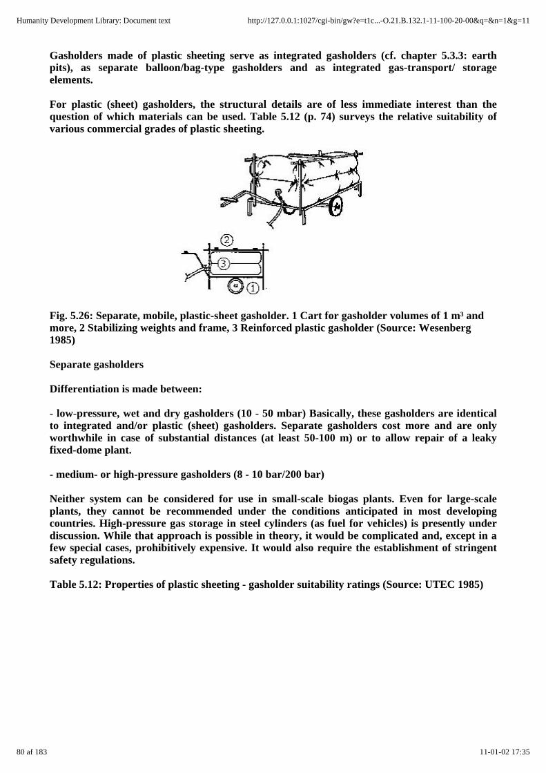
Gasholders made of plastic sheeting serve as integrated gasholders (cf. chapter 5.3.3: earthpits), as separate balloon/bag-type gasholders and as integrated gas-transport/ storageelements.
For plastic (sheet) gasholders, the structural details are of less immediate interest than thequestion of which materials can be used. Table 5.12 (p. 74) surveys the relative suitability ofvarious commercial grades of plastic sheeting.
Fig. 5.26: Separate, mobile, plastic-sheet gasholder. 1 Cart for gasholder volumes of 1 m³ andmore, 2 Stabilizing weights and frame, 3 Reinforced plastic gasholder (Source: Wesenberg1985)
Separate gasholders
Differentiation is made between:
- low-pressure, wet and dry gasholders (10 - 50 mbar) Basically, these gasholders are identicalto integrated and/or plastic (sheet) gasholders. Separate gasholders cost more and are onlyworthwhile in case of substantial distances (at least 50-100 m) or to allow repair of a leakyfixed-dome plant.
- medium- or high-pressure gasholders (8 - 10 bar/200 bar)
Neither system can be considered for use in small-scale biogas plants. Even for large-scaleplants, they cannot be recommended under the conditions anticipated in most developingcountries. High-pressure gas storage in steel cylinders (as fuel for vehicles) is presently underdiscussion. While that approach is possible in theory, it would be complicated and, except in afew special cases, prohibitively expensive. It would also require the establishment of stringentsafety regulations.
Table 5.12: Properties of plastic sheeting - gasholder suitability ratings (Source: UTEC 1985)
80 af 183 11-01-02 17:35
Humanity Development Library: Document text http://127.0.0.1:1027/cgi-bin/gw?e=t1c...-O.21.B.132.1-11-100-20-00&q=&n=1&g=11

Description Mechanical properties Stability/resistance
Material Spec.weight
PermisibleInternalPresure
Slit-tearResistance
MechanicalProperties
TemperatureStability
WeatherResistance
g/m² mbar N - °C -
1 2 3 4 5 6 7 8
Solid PVC 1400 42 50 - 90/65 o
sheeting
per 1.0- PE 950 42 100 - 90/ 70 -/o
mm thick-
ness IIR 1300 9 32 + 170/110 ++
EPDM 1200 4 32 + 170/120 ++
Laminated PVC 750/ 59- 240- ++ 90/65 o
synthetic 1400 80 300
fabrics CPE 1100 - 70
of various CSM 1100 ++ 140/90 ++
thickness CR 1100 ++ 90 ++
81 af 183 11-01-02 17:35
Humanity Development Library: Document text http://127.0.0.1:1027/cgi-bin/gw?e=t1c...-O.21.B.132.1-11-100-20-00&q=&n=1&g=11
2 PVC (polyvinyl chloride) 7 Short-term/continuousload
PE (polyethylene) 11 Permeability coefficient,P, for new material
CPE (chlorinated polyethylene) 12 HF = high-frequencyseam welding
IIR (isobutylene-isoprenerubber)
HW = hot-wedge seamwelding
EPDM (ethylene-propylenediene monomer)
HA = hot-air seam welding
4 Inflatable gasholder, approx.2.5 m³,
C = cementing
3-fold protection againstrupture
HV = hot vulcanizing
6/8/9 - poor, o satisfactory, FF = fusion firing
10/13 + good, ++ very good HT = heat-solvent tapesealing
5.4.5 Gas pipe, valves and fittings
Gas pipe
The following types of gas pipes are in use:
- PVC pipes with adhesive joints
- steel pipes (water supply pipes) with screw couplings
- plastic hoses.
Galvanized steel water supply pipes are used most frequently, because the entire piping system(gas pipe, valves and fittings) can be made of universally applicable English/U.S. Customarysystem components, i.e. with all dimensions in inches. Pipes with nominal dimensions of 1/2" or3/4" are adequate for small-to-midsize plants of simple design and pipe lengths of less than 30m. For larger plants, longer gas pipes or low system pressure, a detailed pressure-loss(pipe-sizing) calculation must be performed (cf. chapter 10.2).
Table 5.13: Gas-pipe pressure losses (Source: OEKOTOP)
82 af 183 11-01-02 17:35
Humanity Development Library: Document text http://127.0.0.1:1027/cgi-bin/gw?e=t1c...-O.21.B.132.1-11-100-20-00&q=&n=1&g=11
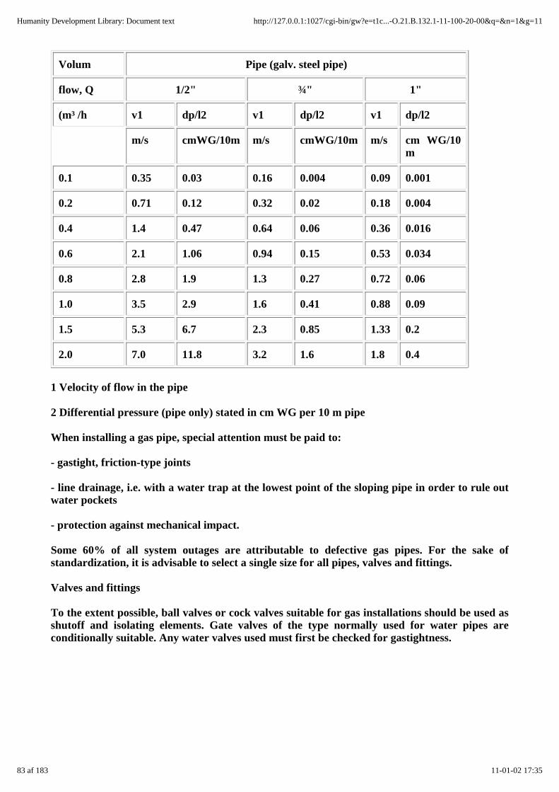
Volum Pipe (galv. steel pipe)
flow, Q 1/2" ¾" 1"
(m³ /h v1 dp/l2 v1 dp/l2 v1 dp/l2
m/s cmWG/10m m/s cmWG/10m m/s cm WG/10m
0.1 0.35 0.03 0.16 0.004 0.09 0.001
0.2 0.71 0.12 0.32 0.02 0.18 0.004
0.4 1.4 0.47 0.64 0.06 0.36 0.016
0.6 2.1 1.06 0.94 0.15 0.53 0.034
0.8 2.8 1.9 1.3 0.27 0.72 0.06
1.0 3.5 2.9 1.6 0.41 0.88 0.09
1.5 5.3 6.7 2.3 0.85 1.33 0.2
2.0 7.0 11.8 3.2 1.6 1.8 0.4
1 Velocity of flow in the pipe
2 Differential pressure (pipe only) stated in cm WG per 10 m pipe
When installing a gas pipe, special attention must be paid to:
- gastight, friction-type joints
- line drainage, i.e. with a water trap at the lowest point of the sloping pipe in order to rule outwater pockets
- protection against mechanical impact.
Some 60% of all system outages are attributable to defective gas pipes. For the sake ofstandardization, it is advisable to select a single size for all pipes, valves and fittings.
Valves and fittings
To the extent possible, ball valves or cock valves suitable for gas installations should be used asshutoff and isolating elements. Gate valves of the type normally used for water pipes areconditionally suitable. Any water valves used must first be checked for gastightness.
83 af 183 11-01-02 17:35
Humanity Development Library: Document text http://127.0.0.1:1027/cgi-bin/gw?e=t1c...-O.21.B.132.1-11-100-20-00&q=&n=1&g=11

Fig. 5.27: Gas pipe, valves and fittings of a biogas plant. 1 Plant shutoff valve, 2 Water trap, 3Pressure gauge, 4 House shutoff valve, 5 Cookstove, 6 Lamp, 7 Appliance shutoff valve, 8Gasmeter (Source: OEKOTOP)
Gas manometer
A U-tube pressure gauge is quick and easy to make and can normally be expected to meet therequirements also of a fixed-dome system.
Fig. 5.28: Gas valves and fittings: U-tube pressure gauge (a), water trap with drain valve (b),U-tube water separator (c), "gravel-pot" flashback arrestor (d). 1 Gas pipe, 2 Condensatecollector, 3 Shutoff valve, 4 Manometer valve, 5 U-tube pressure gauge made of transparenthose, 6 Wooden balls, 7 Antievaporation cap, 8 U-tube, 9 "Gravel-pot" flashback arrestor(approx. 51) filled with 20 mm gravel (Source: OEKOTOP)
Pressure relief
The task of running a fixed-dome system can be made easier by installing a spring-loadedpressure reducing valve that guarantees a constant (adjustable) supply pressure.
Water separation
If at all possible, the water trap should operate automatically. However since fixed-domesystems need a high water seal, often amounting to more than 1 m WG, the use of condensatecollector with a manually operated drain valve is advisable.
84 af 183 11-01-02 17:35
Humanity Development Library: Document text http://127.0.0.1:1027/cgi-bin/gw?e=t1c...-O.21.B.132.1-11-100-20-00&q=&n=1&g=11

Backflow prevention
As a rule, the water trap also functions as a flashback chamber. If deemed necessary, a graveltrap can be installed for added safety.
5.5 Biogas utilization
5.5.1 Composition and properties of biogas
5.5.2 Conditioning of biogas
5.5.3 Biogas appliances
5.5.4 Biogas-fueled engines
5.5.1 Composition and properties of biogas
Biogas is a mixture of gases that is composed chiefly of:
- methane, CH4 40 - 70 vol. %
- carbon dioxide,CO2
30-60 vol. %
- other gases 1 - 5 vol.%,including
- hydrogen H2 0-1 vol. %
- hydrogen sulfide,H2S
0-3 vol. %
Like those of any gas, the characteristic values of biogas are pressure andtemperature-dependent. They are also affected by water vapor. The factors of main interestare:
- volumetric change as a function of temperature and pressure,
- change in value as a function of temperature, pressure and water-vapor con" tent, and
- change in water-vapor content as a function of temperature and pressure.
Chapter 10.2 contains pertinent tables, formulae and nomograms for use in calculatingconditions of state.
5.5.2 Conditioning of biogas
While the biogas produced by the plant can normally be used as it is, i.e. without furthertreatment/conditioning, various conditioning processes are described in this chapter to coverpossible eventualities.
Reducing the moisture content of the biogas, which is usually fully saturated with water vapor.This involves cooling the gas, e.g. by routing it through an underground pipe, so that the excess
85 af 183 11-01-02 17:35
Humanity Development Library: Document text http://127.0.0.1:1027/cgi-bin/gw?e=t1c...-O.21.B.132.1-11-100-20-00&q=&n=1&g=11

water vapor condenses out at the lower temperature. When the gas warms up again, its relativevapor content decreases (cf. chapter 10.2 for calculations). The "drying" of biogas is especiallyuseful in connection with the use of dry gas meters, which otherwise would eventually fill upwith condensed water.
Table 5.14: Composition and properties of biogas, and its constituents under s.t.p. conditions (0°C, 1013 mbar)
(Source: OEKOTOP, compiled from various sources)
Constituents andproperties
CH4 CO2 H2 H2S 60%CH4/40% CO2
65% CH4/34% C02/1% rest
Volume fraction (%) 55-70 27-44 1 3 100 100
Net calorific value(kWh/m³)
9.9 - 3.0 6.3 6.0 6.8
Ignition threshold (% inair)
5-1S - 4-80 4-45 6-12 7.7 - 23
Ignition temperature(°C)
650-750 - 585 - 650-750 650-750
Crit.pressure (bar) 47 75 13 89 75-89 75-89
Crit. temp. (°C) -82.5 31.0 -240 100.0 -82.5 -82.5
Normal density (g/1) 0.72 1.98 0.09 1.54 1.2 1.15
Gas/air-density ratio 0.55 2.5 0.07 1.2 0.83 0.91
Wobbe index, K(kWh/m³)
13.4 - - - 6.59 7.15
Spec. heat, cp (kI/m³ °C) 1.6 1.6 1.3 1.4 1.6 1.6
Flame propagation(cm/s)
43 - 47 - 36 38
Reduction of the hydrogen-sulfide content (H2S) may be necessary if the biogas is found tocontain an excessive amount, i.e. more than 2%, and is to be used for fueling an engine. Since,however, most biogas contains less than 1% H2S, desulfurization is normally unnecessary,especially if it is to be used for operating a stationary engine.
For small-to-midsize systems, desulfurization can be effected by absorption onto ferric hydrate(Fe (OEI)3), also referred to as bog iron, a porous form of limonite. The porous, granularpurifying mass can be regenerated by exposure to air.
The absorptive capacity of the purifying mass depends on its iron-hydrate content: bog ironcontaining 5-10% Fe(OH)3 can absorb about 15 g sulfur per kg without being regenerated andapproximately 150 g/ kg through repetitive regeneration. It is a very noteworthy fact that many
86 af 183 11-01-02 17:35
Humanity Development Library: Document text http://127.0.0.1:1027/cgi-bin/gw?e=t1c...-O.21.B.132.1-11-100-20-00&q=&n=1&g=11

types of tropical soil (laterites) are naturally ferriferous and, hence, suitable for use aspurifying mass.
Reduction of the carbon-dioxide content (CO2) is very complicated and expensive. In principle,CO2 can be removed by absorption onto lime milk, but that practice produces "seas" of limepaste and must therefore be ruled out, particularly in connection with large-scale plants, forwhich only high-tech processes like microscreening are worthy of consideration. CO2"scrubbing" is rarely advisable, except in order to increase the individual bottling capacity forhigh-pressure storage.
Fig. 5.29: Ferric-hydrate gas purifier. 1 Gas pipe, 11 Raw-gas feed pipe, 12 Clean-gas dischargepipe, 13 Purging line, 2 Metal gas purifier, 3 Shelves for purifying mass, 4 Purifying mass(Source: Muche 1984)
Table 5.15: Pointers on flame adjustment (Source: OEKOTOP)
Problem Cause - Remedy
elongated, yellow- ish flame lack of combustion air - open the air supply
flame "lifts off" excessive exit velocity - use smaller injector,reduce the gas pressure, reduce the air supply
flame "flashes back" exit velocity too low - use larger injector, increasethe gas pressure, open the air supply, reduce thesize of the burner jets
flame "too small"; notenough fuel
fuel shortage - use larger injector, increase thegas pressure
flame "too big"; excessivefuel supply/consumption
excessive fuel supply - reduce the gas pressure,use smaller injector
5.5.3 Biogas appliances
87 af 183 11-01-02 17:35
Humanity Development Library: Document text http://127.0.0.1:1027/cgi-bin/gw?e=t1c...-O.21.B.132.1-11-100-20-00&q=&n=1&g=11

Biogas is a lean gas that can, in principle, be used like any other fuel gas for household andindustrial purposes, the main prerequisite being the availability of specially designed biogasburners or modified consumer appliances. The relatively large differences in gas quality fromdifferent plants, and even from one and the same plant (gas pressure, temperature, calorificvalue, etc.) must be given due consideration.
The heart of any gas appliance is the burner. In most cases, atmospheric-type burnersoperating on premixed air/gas fuel are considered preferable.
Due to complex conditions of flow and reaction kinetics, gas burners defy precise calculation, sothat the final design and adjustments must be arrived at experimentally.
Fig. 5.30: Schematic drawing of a biogas burner and its parts. 1 Gas pipe, 2 Gas-flowshutoff/reducing valve, 3 Jets (f = 1-2 mm), 4 Mixing chamber for gas and combustion air, 5Combustion air intake control, 6 Burner head, 7 Injector (Source: Sasse 1984)
Accordingly, the modification and adaptation of commercial-type burners is an experimentalmatter. With regard to butane and propane burners, i.e. the most readily available types, thefollowing pointers are offered:
- Butane/propane gas has up to 3 times the calorific value of biogas and almost twice itsflame-propagation rate.
- Conversion to biogas always results in lower performance values.
Practical modification measures include:
- expanding the injector cross section by a factor of 2-4 in order to increase the flow of gas
- modifying the combustion-air supply, particularly if a combustion-air controller is provided -increasing the size of the jet openings (avoid if possible) The aim of all such measures is toobtain a stable, compact, slightly bluish flame.
Table 5.16: Comparison of various internationally marketed biogas burners (Source:OEKOTOP, compiled. from various sources)
88 af 183 11-01-02 17:35
Humanity Development Library: Document text http://127.0.0.1:1027/cgi-bin/gw?e=t1c...-O.21.B.132.1-11-100-20-00&q=&n=1&g=11

Type of burner¹ Number offlames
Gasconsumption
Burning properties Handling
Peking No. 4/PR China(3)
1 200 l/h + o
Jackwal/Brazil (1) 2 2 X 1501/h ++ +
Patel GC 32/ludia 2 2 X 2501/h o ++
Patel GC 8/India 1 2301/h + ++
KIE burner/Kenya (2) 2 ? + ++
++ very good +good o average
1 Number of burner shown in figure 5.31
Fig. 5.31: Various types of biogas burners. 1 2-flame lightweight burner (2 X 1501/h), 2 2-flamestable burner (2 X 2501/h), 31-flame burner (200 I/h) (Source: OEKOTOP)
Gas cookers/stoves
Biogas cookers and stoves must meet various basic requirements:
- simple and easy operation
- versatility, e.g. for pots of various size, for cooking and broiling
- easy to clean
- acceptable cost and easy repair
- good burning properties, i.e. stable flame, high efficiency
- attractive appearance
A cooker is more than just a burner. It must satisfy certain aesthetic and utility requirements,which can vary widely from region to region. Thus, there is no such thing as an all roundbiogas burner.
Field data shows that 2-flame stable burners are the most popular type (cf. fig. 5.31).
Table 5.17: Biogas consumption for cooking (Source: OEKOTOP, compiled from varioussources)
89 af 183 11-01-02 17:35
Humanity Development Library: Document text http://127.0.0.1:1027/cgi-bin/gw?e=t1c...-O.21.B.132.1-11-100-20-00&q=&n=1&g=11

To be cooked: Gas consumption Time
11 water 30-40 l 8-12 min
51 water 110-140 l 30-40 min
31 broth ~60 l/h
1/2 kg rice 120-140 l ~40 min
1/2 kg legumes 160-190 l ~60 min
1 tortilla(fried) 10-20 l ~3 min
Gas consumption per personand meal
150-300 l/d
Gas consumption per 5-memberfamily
1500 -2400 l/d
(2 cooked meals)
Single-flame burners and lightweight cookstoves tend to be regarded as stop-gap solutions forwant of suitable alternatives.
Biogas cookers require purposive installation with adequate protection from the wind. Beforeany cooker is used, the burner must be carefully adjusted, i.e.:
- for a compact, bluish flame,
- the pot should be cupped by the outer cone of the flame without being touched by the innercone,
- the flame should be self-stabilizing, i.e. flameless zones must re-ignite automatically within 2to 3 seconds.
Test measurements should be performed to optimize the burner setting and minimizeconsumption. The physical efficiency of a typical gas burner ranges from 0.6 to 0.8.
Table 5.18: Tests for biogas cookers/stoves (Source: OEKOTOP)
1. Measuring the efficiency with water
h =- burner efficiency ( - )
QW = quantity of heated water (kg)
T1,T2 = initial and final temperature (°C)
cW = spec. heat capacity = 4.2 kJ/kg
90 af 183 11-01-02 17:35
Humanity Development Library: Document text http://127.0.0.1:1027/cgi-bin/gw?e=t1c...-O.21.B.132.1-11-100-20-00&q=&n=1&g=11

EW = quantity of evaporated water (kg)
L = evaporation heat loss = 2260 kJ/kg
n.c.v. = net cal. value of biogas (kJ/m3 )
Q = quantity of biogas (m3)
——————————————————————————————————————————
2. Gas consumption for holding the temperature at boiling point (simmering temperature -95°C), i.e. the amount of gas needed per unit of time to maintain a water temperature of 95 °C
——————————————————————————————————————————
3. Standard cooking test
This test determines how much gas is- needed to cook a standard meal, e.g. 500 g rice and 1000g water; the standard meal is specified according to the regional staple diet
——————————————————————————————————————————
4. Complete-meal tests
Everything belonging to a complete meal is cooked by a native person.
——————————————————————————————————————————
Fig. 5.32: Schematic drawing of a biogas lamp. 1 Gas pipe, 21 Shutoff valve, 22 Adjusting valve,3 Primary air supply (adjustable), 4 Mixing chamber, 5 Incandescent body - gas mantle, 6Porcelain head, 7 Disk reflector, 8 Glass (Source: OEKOTOP/ Jackwal)
Biogas lamps
The bright light given off by a biogas lamp is the result of incandescence, i.e. the intenseheat-induced luminosity of special metals, so-called "rare earths" like thorium, cerium,lanthanum, etc. at temperature of 1000 - 2000 °C.
At 400-500 lm, the maximum light-flux values that can be achieved with biogas lamps arecomparable to those of a normal 25-75 W light bulb. Their luminous efficiency ranges from 1.2
91 af 183 11-01-02 17:35
Humanity Development Library: Document text http://127.0.0.1:1027/cgi-bin/gw?e=t1c...-O.21.B.132.1-11-100-20-00&q=&n=1&g=11

to 2 Im/W. By comparison, the overall efficiency of a light bulb comes to 3-5 Im/W, and that ofa fluorescent lamp ranges from 10 to 15 lm/W.
The performance of a biogas lamp is depenent on optimal tuning of the incandescent body (gasmantle) and the shape of the flame at the nozzle, i.e. the incandescent body must be surroundedby the inner (= hottest) core of the flame at the minimum gas consumption rate. If theincandescent body is too large, it wil1 show dark spots; if the flame is too large, gasconsumption will be too high for the light-flux yield. The lampshade reflects the lightdownward, and the glass prevents the overly rapid loss of heat.
Table 5.19: Standard lighting terms and units of measure (Source: OEKOTOP)
Term/definition Unit, formula
Luminous flux (F) F, measured in lm (lumen)
The light output defined as the luminousflux of a black body at 2042 °K per cm²
Luminous intensity (I) I, measured in cd (candela)
The solid-angle light power
I = luminous flux / solid angle (w) I = F/w (cd = lm/w)
half-space w = 2 p = 6.28
Illuminance (E) -E, measured in lux (Ix)
light power per unit area
E = luminous flux / area (A) E = F/A (lx = lm/m²)
Spec. illuminance (Es) Es = ((E x r²) / V • n.c.v.)) • (lx • m² / kW)
Effective incident illuminance, asmeasured normal to the light source at adefined distance from the source referredto the input
E = meas. illuminance
r = distance between the incandescent body andthe photoelectric cell
V = biogas consumption n.c.v. = net calorificvalue
Luminous efficiency (Re) light powerreferred to the energy input (Ei)
Re = F/Ei (lm/kW)
Sample calculation
Measured values: Results:
Illuminance Luminous intensity
92 af 183 11-01-02 17:35
Humanity Development Library: Document text http://127.0.0.1:1027/cgi-bin/gw?e=t1c...-O.21.B.132.1-11-100-20-00&q=&n=1&g=11

E=901x I = E x r² = 90 cd
meas. distance, r = 1.0 m luminous flux
gas consumption, V = 110 1/h F = I x w = 90 x 6.28 = 565 lm
cal. value, n.c.v. = 6 kWh/m³ luminous efficiency
Re = F:Q = 565:110 = 5.1 lm/lxh
Re = F/Ei = 565:660 = 0.9 lm/W
Practical experience shows that commercial type biogas lamps are not optimally designed forthe specific conditions of biogas combustion (fluctuating or low pressure, varying gascomposition). The most frequently observed shortcomings are:
- excessively large nozzle cross sections
- excessively large gas mantles
- no possibility of changing the injector
- poor or lacking means of combustion-air control.
Such drawbacks result in unnecessarily high gas consumption and poor lighting. While theexpert/extension officer has practically no influence on how a givenlamp is designed, he can atleast give due consideration to the aforementioned aspects when it comes to selecting aparticular model.
Table 5.20: Comparison of various biogas lamps (Source: Biogas Extension Program)
Type of lamp Suitability1 Gas consumption
D 80 - 3 Juojiang/PR China o 2 ?
Avandela - Jackwal/Brazil + 100 l/h
Patel Outdoor-single/India ++ 150 l/h
Camping-Gas + ?
1 Quality criteria: gas consumption, brightness, control
2 Quality ratings: ++ very good, + good, o average
Biogas lamps are controlled by adjusting the supply of gas and primary air. The aim is to makethe gas mantle burn with uniform brightness and a steady, sputtering murmer (sound ofburning, flowing biogas). To check the criteria, place the glass on the lamp and wait 2 - 5minutes, until the lamp has reached its normal operating temperature. The lamps compared intable 5.20 operate at a gas pressure of 5 - 15 cmWG. If the pressure is any lower, the mantlewill not glow, and if the pressure is too high (fixed-dome systems) the mantle may tear.
93 af 183 11-01-02 17:35
Humanity Development Library: Document text http://127.0.0.1:1027/cgi-bin/gw?e=t1c...-O.21.B.132.1-11-100-20-00&q=&n=1&g=11

Adjusting a biogas lamp requires two consecutive steps:
1. precontrol of the supply of biogas and primary air without the mantle, initially resulting inan elongated flame with a long inner core;
2. fine adjustment with the incandescent body in place, resulting in a brightly glowingincandescent body, coupled with slight further adjustment of the air supply (usually more).
The adjustment is at its best when the dark portions of the incandescent body have justdisappeared. A luxmeter can be used for objective control of the lamp adjustment.
Fig. 5.33: Schematic drawing of a radiant heater. 1 Gas pipe, 2 Shutoff valve, 3 Safety pilot, 31Heat sensor, 4 Mixing chamber, 5 Air supply, 6 Injector, 7 Ceramic panel with protectivescreen, 8 Reflector, 9 Hanger (Source: OEKOTOP / SBM)
Radiant heaters
Infrared heaters are used in agriculture for achieving the. temperatures required for raisingyoung stock, e.g. piglets and chicks, in a limited amount of space. The nursery temperature forpiglets begins at 30-35 °C for the first week and than gradually drops off to an ambienttemperature of 18-23 °C in the 4th/5th week. As a rule, temperature control consists of raisingor lowering the heater. Good ventilation is important in the stable/nursery in order to avoidexcessive concentrations of CO or CO2. Consequently, the animals must be kept under regularsupervision, and the temperature must be checked at regular intervals.
Radiant heaters develop their infrared thermal radiation via a ceramic body that is heated to600-800 °C (red-hot) by the biogas flame.
The heating capacity of the radiant heater is defined by multiplying the gas flow by its netcalorific value (E = Q x n.v.c.), since 95% of the biogas' energy content is converted to heat.Small-heater outputs range from 1.5 to 10 kW thermal power.
Commercial-type heaters are designed for operating on butane, propane and natural gas at asupply pressure of between 30 and 80 mbar. Since the primary air supply is. factory-set,converting a heater for biogas fueling normally consists of replacing the injector; experienceshows that biogas heaters rarely work satisfactorily because the biogas has a low net calorificvalue and the gas supply pressure is below 20 mbar, in which case the ceramic panel is notadequately heated, i.e. the flame does not reach the entire surface, and the heater is verysusceptible to draft.
Biogas-fueled radiant heaters should always be equipped with a safety pilot, and an air filter isrequired for sustained operation in dusty barns.
94 af 183 11-01-02 17:35
Humanity Development Library: Document text http://127.0.0.1:1027/cgi-bin/gw?e=t1c...-O.21.B.132.1-11-100-20-00&q=&n=1&g=11

Table 5.21: Artificial brooding requirements, exemplified for a chick incubator (Source:Wesenberg 1985)
Incubation heat 37.8 °C at the beginning, declining to 30.0 °C at the end of the incubationtemperature should be kept as constant as possible. Any temperature incan damage the eggs.
Hatching time: approximately 21 days
Relative humidity: 60-90 %
Ventilation: A steady supply of fresh air (but not draft) is required to keep the CO20.8 %.
Turning the eggs: Incubating eggs must be turned as often as 8 times a day to keep thesticking to the inside of the shell.
Barren eggs: Unfertilized eggs and eggs containing dead chicks must be removedinfection). The eggs should be candletested once per week to ensure timely
Fig. 5.34: Schematic drawing of an incubator. 1 Incubating chamber, 2 Removable tray, 3Cover/ venting lid, 4 Heating element, 41 Heating coil, 42 Burner, 43 Gas pipe, 5 Water fillerneck and expansion tank, 6 Vent valve, 7 Warming element (plastic hose). Biogas consumptionrate: 30-50 1/h (Source: Wesenberg 1985)
Incubators
95 af 183 11-01-02 17:35
Humanity Development Library: Document text http://127.0.0.1:1027/cgi-bin/gw?e=t1c...-O.21.B.132.1-11-100-20-00&q=&n=1&g=11
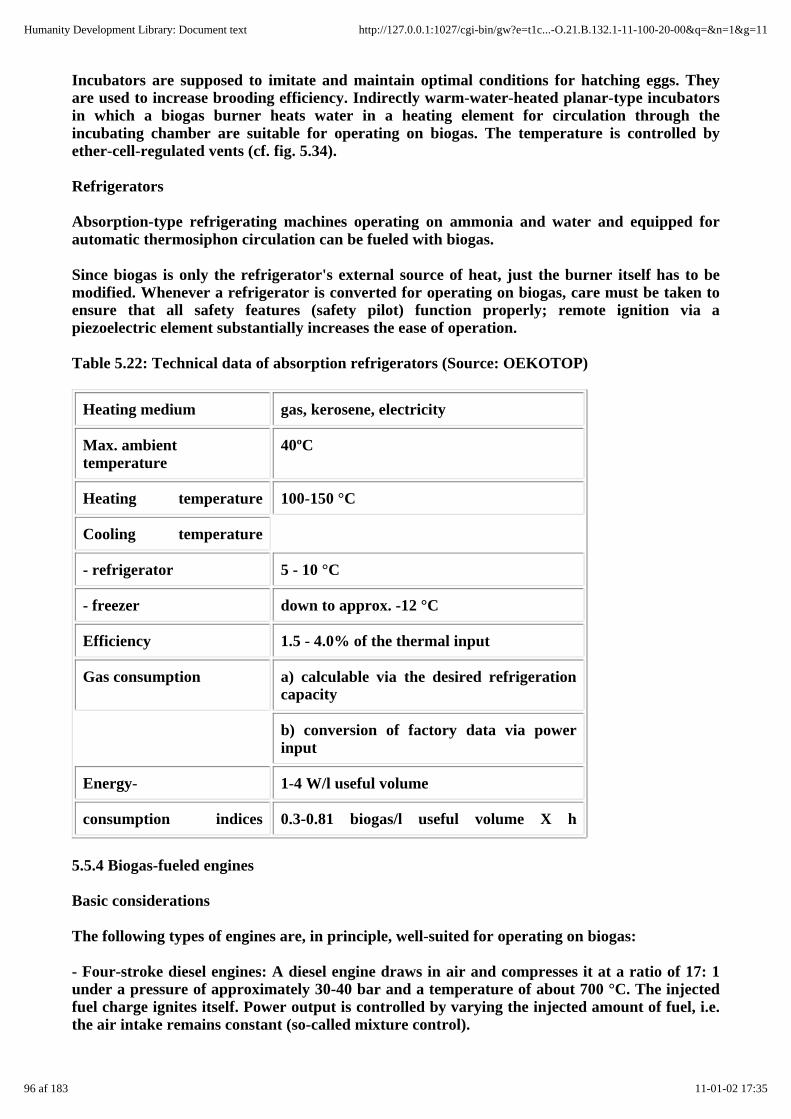
Incubators are supposed to imitate and maintain optimal conditions for hatching eggs. Theyare used to increase brooding efficiency. Indirectly warm-water-heated planar-type incubatorsin which a biogas burner heats water in a heating element for circulation through theincubating chamber are suitable for operating on biogas. The temperature is controlled byether-cell-regulated vents (cf. fig. 5.34).
Refrigerators
Absorption-type refrigerating machines operating on ammonia and water and equipped forautomatic thermosiphon circulation can be fueled with biogas.
Since biogas is only the refrigerator's external source of heat, just the burner itself has to bemodified. Whenever a refrigerator is converted for operating on biogas, care must be taken toensure that all safety features (safety pilot) function properly; remote ignition via apiezoelectric element substantially increases the ease of operation.
Table 5.22: Technical data of absorption refrigerators (Source: OEKOTOP)
Heating medium gas, kerosene, electricity
Max. ambienttemperature
40ºC
Heating temperature 100-150 °C
Cooling temperature
- refrigerator 5 - 10 °C
- freezer down to approx. -12 °C
Efficiency 1.5 - 4.0% of the thermal input
Gas consumption a) calculable via the desired refrigerationcapacity
b) conversion of factory data via powerinput
Energy- 1-4 W/l useful volume
consumption indices 0.3-0.81 biogas/l useful volume X h
5.5.4 Biogas-fueled engines
Basic considerations
The following types of engines are, in principle, well-suited for operating on biogas:
- Four-stroke diesel engines: A diesel engine draws in air and compresses it at a ratio of 17: 1under a pressure of approximately 30-40 bar and a temperature of about 700 °C. The injectedfuel charge ignites itself. Power output is controlled by varying the injected amount of fuel, i.e.the air intake remains constant (so-called mixture control).
96 af 183 11-01-02 17:35
Humanity Development Library: Document text http://127.0.0.1:1027/cgi-bin/gw?e=t1c...-O.21.B.132.1-11-100-20-00&q=&n=1&g=11
- Four-stroke spark-ignition engines: A spark-ignition engine (gasoline engine) draws in amixture of fuel (gasoline or gas) and the required amount of combustion air. The charge isignited by a spark plug at a comparably low compression ratio of between 8: 1 and 12: 1. Powercontrol is effected by varying the mixture intake via a throttle (so-called charge control).
Four-stroke diesel and spark-ignition engines are available in standard versions with powerratings ranging from 1 kW to more than 100 kW. Less suitable for biogas fueling are:
- loop-scavenging 2-stroke engines in which lubrication is achieved by adding oil to the liquidfuel, and
- large, slow-running (less than 1000 r.p.m.) engines that are not built in large series, since theyare accordingly expensive and require complicated control equipment.
Biogas engines are generally suitable for powering vehicles like tractors and light-duty trucks(pickups, vans). The fuel is contained in 200-bar steel cylinders (e.g. welding-gas cylinders). Thetechnical, safety, instrumentational and energetic cost of gas compression, storage and filing issubstantial enough to hinder large-scale application. Consequently, only stationary engines arediscussed below.
Essential terms and definitions
Knowledge of the following terms pertaining to internal combustion engines is requisite tounderstanding the context:
Piston displacement is the volume (cm³, l) displaced by a piston in a cylinder in a single stroke,i.e. between the bottom and . top dead-canter positions (BDC and TDC, respectively). The totalcylinder capacity (Vtot) comprises the swept volume (Vs) and the compression volume (Vc), i.e.Vtot = Vs+Vc.
The compression ratio (E) is the ratio of the maximum to the minimum volume of the spaceenclosed by the piston, i.e. prior to compression (Vtot) as compared to the end of thecompression stroke (Vc). The compression ratio can be used to calculate the pressure andtemperature of the compressed fuel mixture (E = Vtot/Vc).
The efficiency (rl = Pc/Pf) is the ratio between the power applied to the crankshaft (Pc) and theamount of energy introduced with the fuel (Pf = V x n.c.v.).
Ignition and combustion: The firing point (diesel: flash point; spark-ignition engine: ignitionpoint) is timed to ensure that the peak pressure is reached just after the piston passes top deadcenter (approx. 10° - 15° crankshaft angle). Any deviation from the optimal fiash/ignition pointleads to a loss of power and efficiency; in extreme cases, the engine may even suffer damage.The flash/ignition point is chosen on the basis of the time history of combustion, i.e. the rate ofcombustion, and depends on the compression pressure, type of fuel, combustion-air/ fuel ratioand the engine speed. The ignition timing (combustion) must be such that the air/fuel mixture isfully combusted at the end of the combustion cycle, i.e. when the exhaust valve opens, since partof the fuel's energy content would otherwise be wasted.
Air/Fuel-ratio and control: Proper combustion requires a fuel-dependent stoichiometricair/fuel-ratio (af-ratio). As a rule, the quality of combustion is maximized by increasing the airfraction, as expressed by the air-ratio coefficient (d = actual air volume/stoichiometric airvolume).
For gasoline and gas-fueled engines, the optimal air/fuel ratio is situated somewhere within the
97 af 183 11-01-02 17:35
Humanity Development Library: Document text http://127.0.0.1:1027/cgi-bin/gw?e=t1c...-O.21.B.132.1-11-100-20-00&q=&n=1&g=11

range d = 0.8 - 1.3, with maximum power output at 0.9 and maximum efficiency (and cleanexhaust) at 1.1. The power output is controlled by varying the mixture intake and, hence, thecylinder's volumetric efficient and final pressure, via the throttle. Diesel engines require anair-ratio of d = 1.3 at full load and 4 - 6 at low load, i.e. fuel intake is reduced, while the airintake remains constant.
Converting diesel engines
Diesel engines are designed for continuous operation (10 000 or more operating hours).Basically, they are well-suited for conversion to biogas according to either of two methods:
The dual-fuel approach
Except for the addition of a gas/air mixing chamber on the intake manifold (if need be, the airfilter can be used as a mixing chamber), the diesel engine remains extensively unmodified. Theinjected diesel fuel still ignites itself, while the amount injected is automatically reduced by thespeed governor, depending on how much biogas is introduced into the mixing chamber. Thebiogas supply is controlled by hand. The maximum biogas intake must be kept below the pointat which the engine would begin to stutter. If that happens, the governor is getting too muchbiogas and has therefore turned down the diesel intake so far that ignition is no longer steady.Normally, 15 - 20% diesel is sufficiency, meaning that as much as 80% of the diesel fuel can bereplaced by biogas. Any lower share of biogas can also be used, of course, since the governerautomatically compensates with more diesel.
As a rule, dual-fuel diesels perform just as well as a comparable engine operating on purediesel.
As in normal diesel operation, the speed is controlled by an accelerator lever, and load controlis normally effected by hand, i.e. by adjusting the biogas valve (keeping in mind the maximumacceptable biogas intake level). In case of frequent power changes joined with steady speed, thebiogas fraction should be reduced somewhat to let the governer decrease the diesel intakewithout transgressing the minimum amount. Thus, the speed is kept constant, even in case ofpower cycling. Important: No diesel engine should be subjected to air-side control.
While special T-pieces or mixing chambers with 0.5 to 1.0 times the engine displacement canserve as the diesel/biogas mixing chamber, at which a true mixing chamber offers theadvantage of more thorough mixing.
Conversion according to the dual-fuel method is evaluated as follows
- a quick & easy do-it-yourself technique
- will accommodate an unsteady supply of biogas
- well-suited for steady operation, since a single manual adjustment will suffice
- requires a minimum share of diesel to ensure ignition.
Conversion to spark ignition (Otto cycle)
involves the following permanent alterations to the engine:
- removing the fuel-injection pump and nozzle
- adding an ignition distributor and an ignition coil with power supply (battery or dynamo)
98 af 183 11-01-02 17:35
Humanity Development Library: Document text http://127.0.0.1:1027/cgi-bin/gw?e=t1c...-O.21.B.132.1-11-100-20-00&q=&n=1&g=11
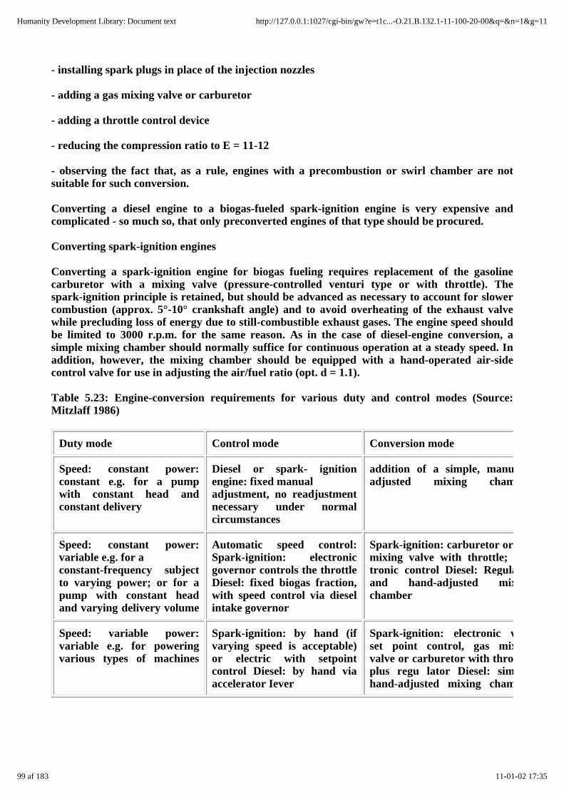
- installing spark plugs in place of the injection nozzles
- adding a gas mixing valve or carburetor
- adding a throttle control device
- reducing the compression ratio to E = 11-12
- observing the fact that, as a rule, engines with a precombustion or swirl chamber are notsuitable for such conversion.
Converting a diesel engine to a biogas-fueled spark-ignition engine is very expensive andcomplicated - so much so, that only preconverted engines of that type should be procured.
Converting spark-ignition engines
Converting a spark-ignition engine for biogas fueling requires replacement of the gasolinecarburetor with a mixing valve (pressure-controlled venturi type or with throttle). Thespark-ignition principle is retained, but should be advanced as necessary to account for slowercombustion (approx. 5°-10° crankshaft angle) and to avoid overheating of the exhaust valvewhile precluding loss of energy due to still-combustible exhaust gases. The engine speed shouldbe limited to 3000 r.p.m. for the same reason. As in the case of diesel-engine conversion, asimple mixing chamber should normally suffice for continuous operation at a steady speed. Inaddition, however, the mixing chamber should be equipped with a hand-operated air-sidecontrol valve for use in adjusting the air/fuel ratio (opt. d = 1.1).
Table 5.23: Engine-conversion requirements for various duty and control modes (Source:Mitzlaff 1986)
Duty mode Control mode Conversion mode
Speed: constant power:constant e.g. for a pumpwith constant head andconstant delivery
Diesel or spark- ignitionengine: fixed manualadjustment, no readjustmentnecessary under normalcircumstances
addition of a simple, manuallyadjusted mixing chamber
Speed: constant power:variable e.g. for aconstant-frequency subjectto varying power; or for apump with constant headand varying delivery volume
Automatic speed control:Spark-ignition: electronicgovernor controls the throttleDiesel: fixed biogas fraction,with speed control via dieselintake governor
Spark-ignition: carburetor ormixing valve with throttle; electronic control Diesel: Regulatorand hand-adjusted mixingchamber
Speed: variable power:variable e.g. for poweringvarious types of machines
Spark-ignition: by hand (ifvarying speed is acceptable)or electric with setpointcontrol Diesel: by hand viaaccelerator Iever
Spark-ignition: electronic withset point control, gas mixingvalve or carburetor with throttle,plus regu lator Diesel: simple,hand-adjusted mixing chamber
99 af 183 11-01-02 17:35
Humanity Development Library: Document text http://127.0.0.1:1027/cgi-bin/gw?e=t1c...-O.21.B.132.1-11-100-20-00&q=&n=1&g=11

Fig. 5.35: Various gas mixers for spark-ignition and diesel engines. 1 Air intake, 2 Air filter, 3Biogas supply pipe, 4 Biogas control valve, 5 Mixing chamber (0.5 - 1 X piston displacement) 6Throttle, 7 Mixing valve (Source: OEKOTOP)
Converting a spark-ignition engine results in a loss of performance amounting to as much as3070. While partial compensation can be achieved by raising the compression ratio to E =11-12, such a measure also in,creases the mechanical and thermal load on the engine.
Spark-ignition engines that are not expressly marketed as suitable for running on gas orunleaded gasoline may suffer added wear & tear due to the absence of lead lubrication.
The speed control of converted spark-ignition engines is effected by way of a hand-operatedthrottle. Automatic speed control for different load conditions requires the addition of anelectronic control device for the throttle.
The conversion of spark-ignition engines is evaluated as follows:
- Gasoline engines are readily available in the form of vehicle motors, but their useful lifeamounts to a mere 3000 - 4000 operating hours.
- The conversion effort essentially consists of adding a (well-tuned) gas mixer.
- Gasoline engines are not as durable as diesel engines.
Engine selection and operation
Speed
Since biogas burns relatively slowly, biogas-fueled engines should be operated at
- 1300-2000 r.p.m. (diesel)
- 1500-3000 r.p.m. (spark-ignition)
The standard speeds for such engines are 1500 and 3000 r.p.m. (50 Hz) or 1800/3600 r.p.m. (60Hz) because of connecting a generator. For direct-power applications, i.e. a V-belt drive, the
100 af 183 11-01-02 17:35
Humanity Development Library: Document text http://127.0.0.1:1027/cgi-bin/gw?e=t1c...-O.21.B.132.1-11-100-20-00&q=&n=1&g=11

transmission ratio should ensure that the engine operates within its best efficiency range (=lowest fuel consumption) under normal-power conditions.
(f engine-end pulley speed of machine)/(f machine-end pulley)= (speed of machine)/(speed ofengine)
Consumption
Depending on the gas composition, barometric pressure and type of engine, the specificconsumption will amount to 0.5-0.8 m³/ kWh, i.e. a 10-kW engine will use 5-8 m³ biogas perhour. In a dual-fuel setup, the biogas consumption rate can be reduced by lowering the biogasfraction.
Fig. 5.36: Consumption of diesel and biogas by a 10-kW engine (1 cyl., 1000 ccm), 1300 m abovesea level, running at 1500 r.p.m. 1 Biogas consumption in dual-fuel operation, 2 Dieselconsumption in pure diesel operation, 3 Diesel consumption in dual-fuel operation, 4 Dieselsaving, 5 Efficiency in diesel operation, 6 Efficiency in dual-fuel operation (Source: Mitzlaff1986)
Maintenance and useful life
In contact with water, the H2S content of biogas promotes corrosion. Consequently, adherence
to the prescribed oil-change intervals is very important (after each 100 operating hours or sofor vehicle spark-ignition engines). Dual-fuel engines should be started on pure diesel, withbiogas being added gradually after about 2 minutes. For shutdown, the biogas fraction should
101 af 183 11-01-02 17:35
Humanity Development Library: Document text http://127.0.0.1:1027/cgi-bin/gw?e=t1c...-O.21.B.132.1-11-100-20-00&q=&n=1&g=11
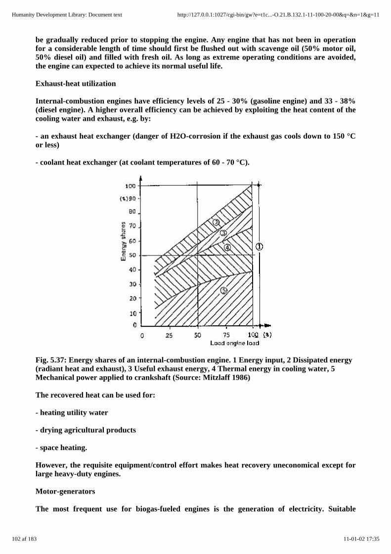
be gradually reduced prior to stopping the engine. Any engine that has not been in operationfor a considerable length of time should first be flushed out with scavenge oil (50% motor oil,50% diesel oil) and filled with fresh oil. As long as extreme operating conditions are avoided,the engine can expected to achieve its normal useful life.
Exhaust-heat utilization
Internal-combustion engines have efficiency levels of 25 - 30% (gasoline engine) and 33 - 38%(diesel engine). A higher overall efficiency can be achieved by exploiting the heat content of thecooling water and exhaust, e.g. by:
- an exhaust heat exchanger (danger of H2O-corrosion if the exhaust gas cools down to 150 °Cor less)
- coolant heat exchanger (at coolant temperatures of 60 - 70 °C).
Fig. 5.37: Energy shares of an internal-combustion engine. 1 Energy input, 2 Dissipated energy(radiant heat and exhaust), 3 Useful exhaust energy, 4 Thermal energy in cooling water, 5Mechanical power applied to crankshaft (Source: Mitzlaff 1986)
The recovered heat can be used for:
- heating utility water
- drying agricultural products
- space heating.
However, the requisite equipment/control effort makes heat recovery uneconomical except forlarge heavy-duty engines.
Motor-generators
The most frequent use for biogas-fueled engines is the generation of electricity. Suitable
102 af 183 11-01-02 17:35
Humanity Development Library: Document text http://127.0.0.1:1027/cgi-bin/gw?e=t1c...-O.21.B.132.1-11-100-20-00&q=&n=1&g=11
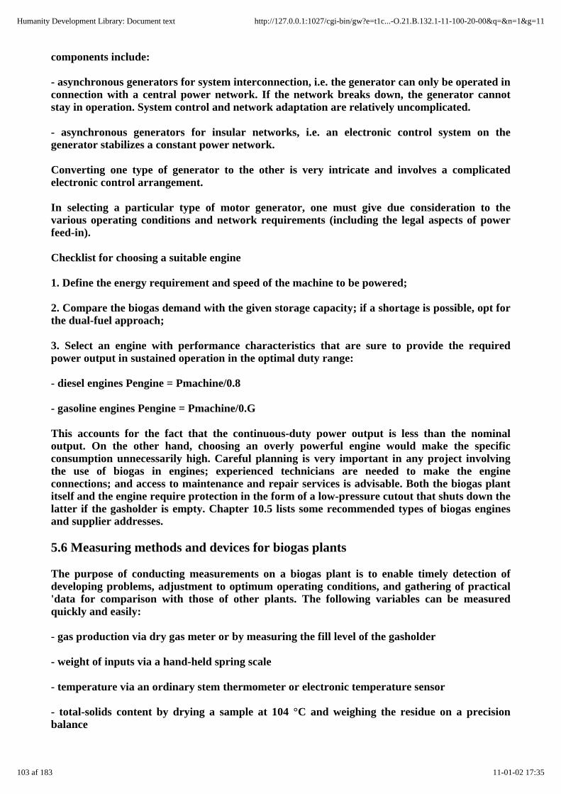
components include:
- asynchronous generators for system interconnection, i.e. the generator can only be operated inconnection with a central power network. If the network breaks down, the generator cannotstay in operation. System control and network adaptation are relatively uncomplicated.
- asynchronous generators for insular networks, i.e. an electronic control system on thegenerator stabilizes a constant power network.
Converting one type of generator to the other is very intricate and involves a complicatedelectronic control arrangement.
In selecting a particular type of motor generator, one must give due consideration to thevarious operating conditions and network requirements (including the legal aspects of powerfeed-in).
Checklist for choosing a suitable engine
1. Define the energy requirement and speed of the machine to be powered;
2. Compare the biogas demand with the given storage capacity; if a shortage is possible, opt forthe dual-fuel approach;
3. Select an engine with performance characteristics that are sure to provide the requiredpower output in sustained operation in the optimal duty range:
- diesel engines Pengine = Pmachine/0.8
- gasoline engines Pengine = Pmachine/0.G
This accounts for the fact that the continuous-duty power output is less than the nominaloutput. On the other hand, choosing an overly powerful engine would make the specificconsumption unnecessarily high. Careful planning is very important in any project involvingthe use of biogas in engines; experienced technicians are needed to make the engineconnections; and access to maintenance and repair services is advisable. Both the biogas plantitself and the engine require protection in the form of a low-pressure cutout that shuts down thelatter if the gasholder is empty. Chapter 10.5 lists some recommended types of biogas enginesand supplier addresses.
5.6 Measuring methods and devices for biogas plants
The purpose of conducting measurements on a biogas plant is to enable timely detection ofdeveloping problems, adjustment to optimum operating conditions, and gathering of practical'data for comparison with those of other plants. The following variables can be measuredquickly and easily:
- gas production via dry gas meter or by measuring the fill level of the gasholder
- weight of inputs via a hand-held spring scale
- temperature via an ordinary stem thermometer or electronic temperature sensor
- total-solids content by drying a sample at 104 °C and weighing the residue on a precisionbalance
103 af 183 11-01-02 17:35
Humanity Development Library: Document text http://127.0.0.1:1027/cgi-bin/gw?e=t1c...-O.21.B.132.1-11-100-20-00&q=&n=1&g=11

- H2S content of the gases via a gas test tube
- pH via litmus paper.
The contents of the substrate/slurry can only be determined by a special laboratory.
Various levels of precision are recommended, depending on the set objective and correspondingtime, effort and equipment expenditure.
Observation by the user
Procedure
- measuring the gas consumption through daily checking of the calibration marks on thegasholder
- measuring the daily input quantities via defined-volume vessels
- measuring the air/slurry temperature with a thermometer.
Documentation
Daily notation of measured values.
Interpretation/results
Daily gas production as a function of substrate input and temperature.
Field testing by the extension officer
Procedure
- installation and daily reading of a dry gas meter to determine the rate of gas production
- random sampling of the CO2 and H2S contents of the biogas
- determination of quantities added by weighing the moist mass and water on a spring scale
- random sampling to determine the total solids content of the substrate
- measuring the digester temperature with the aid of a remote electronic thermometer
- measuring the ambient temperature with a mini-max thermometer
- determining pH levels via litmus paper
- laboratory testing to determine the C/Nratio, volatile solids content and manurial quality ofdigested slurry.
104 af 183 11-01-02 17:35
Humanity Development Library: Document text http://127.0.0.1:1027/cgi-bin/gw?e=t1c...-O.21.B.132.1-11-100-20-00&q=&n=1&g=11
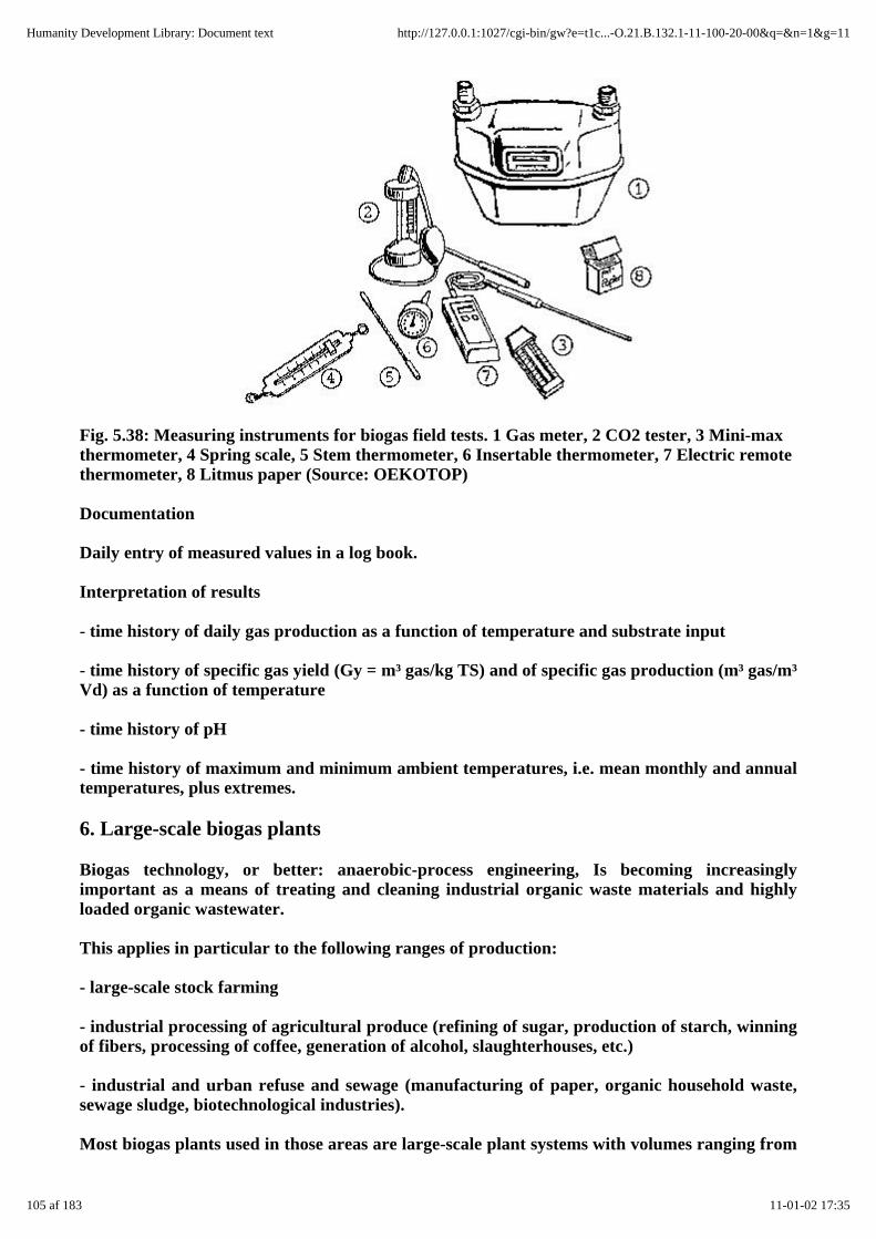
Fig. 5.38: Measuring instruments for biogas field tests. 1 Gas meter, 2 CO2 tester, 3 Mini-maxthermometer, 4 Spring scale, 5 Stem thermometer, 6 Insertable thermometer, 7 Electric remotethermometer, 8 Litmus paper (Source: OEKOTOP)
Documentation
Daily entry of measured values in a log book.
Interpretation of results
- time history of daily gas production as a function of temperature and substrate input
- time history of specific gas yield (Gy = m³ gas/kg TS) and of specific gas production (m³ gas/m³Vd) as a function of temperature
- time history of pH
- time history of maximum and minimum ambient temperatures, i.e. mean monthly and annualtemperatures, plus extremes.
6. Large-scale biogas plants
Biogas technology, or better: anaerobic-process engineering, Is becoming increasinglyimportant as a means of treating and cleaning industrial organic waste materials and highlyloaded organic wastewater.
This applies in particular to the following ranges of production:
- large-scale stock farming
- industrial processing of agricultural produce (refining of sugar, production of starch, winningof fibers, processing of coffee, generation of alcohol, slaughterhouses, etc.)
- industrial and urban refuse and sewage (manufacturing of paper, organic household waste,sewage sludge, biotechnological industries).
Most biogas plants used in those areas are large-scale plant systems with volumes ranging from
105 af 183 11-01-02 17:35
Humanity Development Library: Document text http://127.0.0.1:1027/cgi-bin/gw?e=t1c...-O.21.B.132.1-11-100-20-00&q=&n=1&g=11
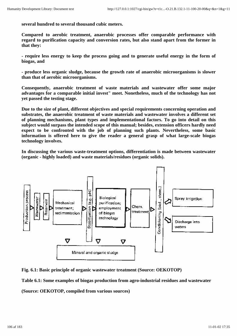
several hundred to several thousand cubic meters.
Compared to aerobic treatment, anaerobic processes offer comparable performance withregard to purification capacity and conversion rates, but also stand apart from the former inthat they:
- require less energy to keep the process going and to generate useful energy in the form ofbiogas, and
- produce less organic sludge, because the growth rate of anaerobic microorganisms is slowerthan that of aerobic microorganisms.
Consequently, anaerobic treatment of waste materials and wastewater offer some majoradvantages for a comparable initial invest" meet. Nonetheless, much of the technology has notyet passed the testing stage.
Due to the size of plant, different objectives and special requirements concerning operation andsubstrates, the anaerobic treatment of waste materials and wastewater involves a different setof planning mechanisms, plant types and implementational factors. To go into detail on thissubject would surpass the intended scope of this manual; besides, extension officers hardly needexpect to be confronted with the job of planning such plants. Nevertheless, some basicinformation is offered here to give the reader a general grasp of what large-scale biogastechnology involves.
In discussing the various waste-treatment options, differentiation is made between wastewater(organic - highly loaded) and waste materials/residues (organic solids).
Fig. 6.1: Basic principle of organic wastewater treatment (Source: OEKOTOP)
Table 6.1: Some examples of biogas production from agro-industrial residues and wastewater
(Source: OEKOTOP, compiled from various sources)
106 af 183 11-01-02 17:35
Humanity Development Library: Document text http://127.0.0.1:1027/cgi-bin/gw?e=t1c...-O.21.B.132.1-11-100-20-00&q=&n=1&g=11
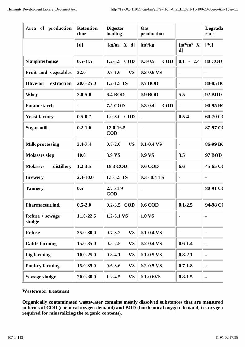
Area of production Retentiontime
Digesterloading
Gasproduction
Degradationrate
[d] [kg/m³ X d] [m³/kg] [m³/m³ Xd]
[%]
Slaughterhouse 0.5- 8.5 1.2-3.5 COD 0.3-0.5 COD 0.1 - 2.4 80 COD
Fruit and vegetables 32.0 0.8-1.6 VS 0.3-0.6 VS - -
Olive-oil extraction 20.0-25.0 1.2-1.5 TS 0.7 BOD - 80-85 BOD
Whey 2.0-5.0 6.4 BOD 0.9 BOD 5.5 92 BOD
Potato starch - 7.5 COD 0.3-0.4 COD - 90-95 BOD
Yeast factory 0.5-0.7 1.0-8.0 COD - 0.5-4 60-70 COD
Sugar mill 0.2-1.0 12.0-16.5COD
- - 87-97 COD
Milk processing 3.4-7.4 0.7-2.0 VS 0.1-0.4 VS - 86-99 BOD
Molasses slop 10.0 3.9 VS 0.9 VS 3.5 97 BOD
Molasses distillery 1.2-3.5 18.3 COD 0.6 COD 6.6 45-65 COD
Brewery 2.3-10.0 1.8-5.5 TS 0.3 - 0.4 TS - -
Tannery 0.5 2.7-31.9COD
- - 80-91 COD
Pharmaceut.ind. 0.5-2.0 0.2-3.5 COD 0.6 COD 0.1-2.5 94-98 COD
Refuse + sewagesludge
11.0-22.5 1.2-3.1 VS 1.0 VS - -
Refuse 25.0-30.0 0.7-3.2 VS 0.1-0.4 VS - -
Cattle farming 15.0-35.0 0.5-2.5 VS 0.2-0.4 VS 0.6-1.4 -
Pig farming 10.0-25.0 0.8-4.1 VS 0.1-0.5 VS 0.8-2.1 -
Poultry farming 15.0-35.0 0.6-3.6 VS 0.2-0.5 VS 0.7-1.8 -
Sewage sludge 20.0-30.0 1.2-4.5 VS 0.1-0.6VS 0.8-1.5 -
Wastewater treatment
Organically contaminated wastewater contains mostly dissolved substances that are measuredin terms of COD (chemical oxygen demand) and BOD (biochemical oxygen demand, i.e. oxygenrequired for mineralizing the organic contents).
107 af 183 11-01-02 17:35
Humanity Development Library: Document text http://127.0.0.1:1027/cgi-bin/gw?e=t1c...-O.21.B.132.1-11-100-20-00&q=&n=1&g=11

The main purpose of wastewater treatment is to remove or mineralize the organic substances,i.e. to prepare them for release into a receiving body of water or the agricultural environment.
Anaerobic fermentation serves as the biological purifying process. Purification performancerates of up to 95% BOD are achievable. The choice of process and the achievable purificationperformance rates are determined by the type and composition of the substrate/wastewater. Ingeneral, dissolved organic substances are readily biodegradable. Retention times ranging froma few hours to a few days are not uncommon. On the other hand, some organic substances arehard to break down (paints, aromates, etc.), while others are toxic and/o,r capable of causing ashortage of nutrients and adverse medium characteristics (e.g. pH-shifts). A number ofspecial-purpose processes have been developed for use in anaerobic wastewater treatment inorder to compensate for the high hydraulic loads and lack of bacterial colonization areas:
Contact fermenter
Digested slurry is recycled through a continuously stirred reactor in order to maintain a highlevel of bacterial concentration and, hence high performance. The contact process is a suitableapproach for both mobile substrates and substrates with a high concentration of solids.
Upflow fermenter
An upflow-type fermenter with a special hydraulic configuration serves simultaneously as asuspended-solids filter with a high bacterial density and correspondingly high biodegradationperformance.
Fluidized-bed fermenter
A vehicle (balls of plastic or clay) is kept "floating" in the fermenter to serve as a colonizingarea for the bacteria.
Fixed-bed fermenter
A vehicle (plastic pellets or lumps of clay, rock or glass) provides a large, stationarycolonization area within the fermenter. Fixed-bed fermenters are suitable for wastewatercontaining only dissolved solids. If the wastewater also contains suspended solids, the fermenteris liable to plug up.
Two-phase fermentation
The acidic and methanogenic phases of fermentation are conducted separately, each under itsown optimum conditions, in order to maximize the fermentation rates and achieve good gasquality.
The treatment of wastewater marked by heavy organic pollution must always be looked uponas an individual problem that may require different processes from one case to the next, eventhough the initial products are identical. Consequently, trials must always be conducted for theentire chain: production process - purification - wastewater utilization - and energy supply/ use.
Thanks to their uncomplicated, robust equipment, the contact process and fixed-bedfermentation stand the best chance of success in developing countries.
Waste materials/residues
The fact that practically identical production processes often yield residues that hardlyresemble one another also applies to industrial waste materials. Here, too, pretrials and
108 af 183 11-01-02 17:35
Humanity Development Library: Document text http://127.0.0.1:1027/cgi-bin/gw?e=t1c...-O.21.B.132.1-11-100-20-00&q=&n=1&g=11

individual, problem-specific testing are called for in any case.
The potential range of organic waste materials is practically unlimited. Of particular interestfor the purposes of this manual, however, are waste materials from factory farms andslaughterhouses.
Large-scale stock farming
The characteristics of dung from cattle, pigs and chickens were described in chapter 3.2. Infactory farming, the dung yield is heavily dependent on the given type of fodder and how thestables are cleaned. Thus, pinpoint inquiries are always necessary.
The large quantities of substrate, often exceeding 50 m³/d, lead to qualitative differences in theplanning and implementation of large-scale plants, as opposed to small-scale plants. This hasconsequences with regard to substrate handling and size of plant:
- Daily substrate-input volumes of more than 1 m³ cannot be managed by hand. Pumps forfiling the plant and machines for chopping up the substrate are expensive to buy and run, inaddition to being susceptible to wear & tear. In many cases, careful planning can make itpossible to use gravity-flow channels for filling the plant.
- Plants of a size exceeding 100 m³ usually cannot be made of masonry, i.e. the types of plantdiscussed in chapter 5 cannot be used.
The choice of plant is limited to either the mechanized types used in industrial countries orsimple, large-scale plants. Experience shows that most simple, large-scale plants are
- of modular design,
- usually equipped with channel digesters,
- and require the use of substrate from which the scum-forming material has been removed inorder to get by with either low-power mechanical mixers or none at all.
Since large-scale biogas plants produce accordingly large volumes of biogas, the generation ofelectricity with the aid of a motor-generator set is of main interest.
The two Ferkessedougou biogas plants situated in the northern part of Cote d' Ivoire stand asexamples of a successful large-scale biogas-plant concept based on a simple design. They havebeen in operation at the local cattle-fattening station and slaughterhouse since 1982 and 1986,respectively, where they serve in the disposal of some of the excrements produced by anaverage number of 2500 head of cattle. The plant consists of a simple, unlined earth-pit digesterwith a plastic-sheet cover serving as gasholder. The gas is used for generating electricity,heating water and producing steam.
Fig. 6.2: Biogas plant in Ferkessedougou - system OEKOTOP. 1 Cattle feedlot, 2 Manure
109 af 183 11-01-02 17:35
Humanity Development Library: Document text http://127.0.0.1:1027/cgi-bin/gw?e=t1c...-O.21.B.132.1-11-100-20-00&q=&n=1&g=11

gutter, 3 Feedpipe, 4 Sluice, 5 Rubber-sheet gasholder, 6 Earth-pit digester, 7 Discharge pipe, 8Impounding weir, 9 Slurry storage (Source: OEKOTOP)
At present, some 20% of the slaughterhouse's electricity requirement is covered by the biogasplants, and the biogas-driven steam sterilizer saves 50 000 I diesel fuel each year. The totalinitial investment amounting to 60 million F.CFA yields annual savings of approximately 12million F.CFA after deduction of the operating costs (1 DM = 150 F.CFA).
The Ferkessedougou biogas plants demonstrate how even large-scale installations can keepbiogas technology cost-efficient by relying on simple designs, e.g. large digester volume despitelow cost of construction.
Table 6.2: Technical data of the Ferkessedougou biogas plant (Source: OEKOTOP)
Biogas plant I Biogas plant II
No. of animals 700 head of cattle in 12feedlots
Digester volume 400 m³ 810 m³
Gasholder volume 80 m³ >600 m³
Slurry storage volume 300 m³ 3500 m³
Retention time 40-2s days 40 -22 days
Daily substrate input1 10-18 m³/d 20-38 m³/d
TS-content 4-8%
Daily gas production 250 m³/d 450 m³/d
Specific gas production 0.6 m³/m³ Vd 0.55 m³/m³ Vd
Gas utilization MWM gas-powered Deutz gas-powered
motor-generator set motor generator set
15 kWel 32 kWel, with exhaust heat recoverywater
Operating time 22 h/d 10 h/d
Power generation 270 kWh/d 245 kWh/d
Combination gas-oil burner for steam130-355 kW
1 Fluctuation due to seasonal factors (rainy/dry season)
Slaughterhouses
110 af 183 11-01-02 17:35
Humanity Development Library: Document text http://127.0.0.1:1027/cgi-bin/gw?e=t1c...-O.21.B.132.1-11-100-20-00&q=&n=1&g=11
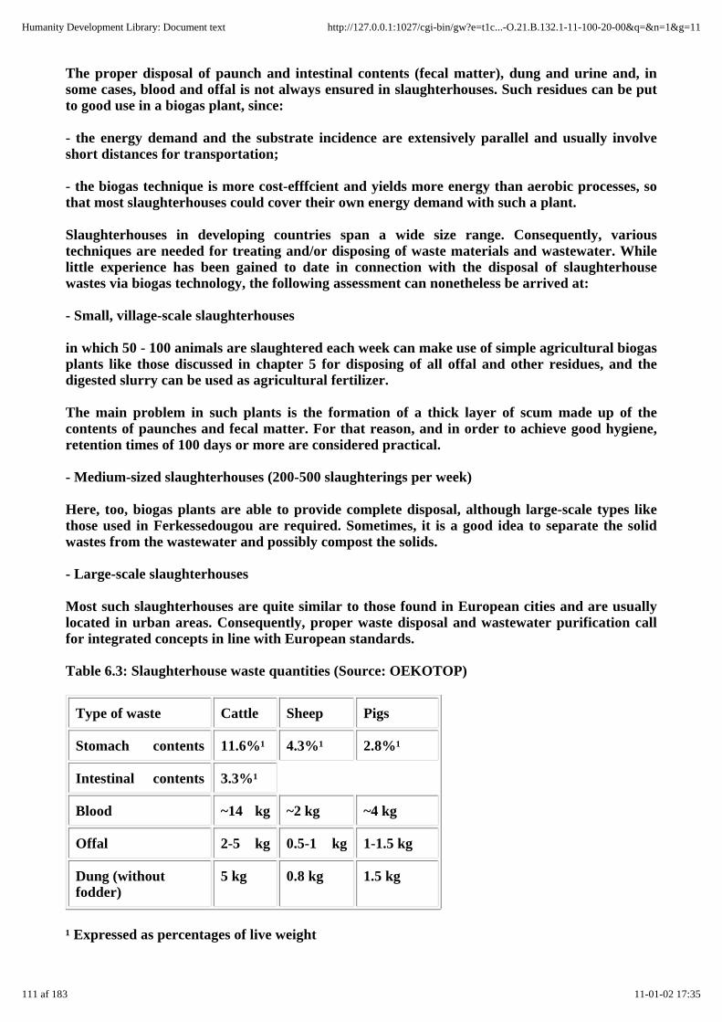
The proper disposal of paunch and intestinal contents (fecal matter), dung and urine and, insome cases, blood and offal is not always ensured in slaughterhouses. Such residues can be putto good use in a biogas plant, since:
- the energy demand and the substrate incidence are extensively parallel and usually involveshort distances for transportation;
- the biogas technique is more cost-efffcient and yields more energy than aerobic processes, sothat most slaughterhouses could cover their own energy demand with such a plant.
Slaughterhouses in developing countries span a wide size range. Consequently, varioustechniques are needed for treating and/or disposing of waste materials and wastewater. Whilelittle experience has been gained to date in connection with the disposal of slaughterhousewastes via biogas technology, the following assessment can nonetheless be arrived at:
- Small, village-scale slaughterhouses
in which 50 - 100 animals are slaughtered each week can make use of simple agricultural biogasplants like those discussed in chapter 5 for disposing of all offal and other residues, and thedigested slurry can be used as agricultural fertilizer.
The main problem in such plants is the formation of a thick layer of scum made up of thecontents of paunches and fecal matter. For that reason, and in order to achieve good hygiene,retention times of 100 days or more are considered practical.
- Medium-sized slaughterhouses (200-500 slaughterings per week)
Here, too, biogas plants are able to provide complete disposal, although large-scale types likethose used in Ferkessedougou are required. Sometimes, it is a good idea to separate the solidwastes from the wastewater and possibly compost the solids.
- Large-scale slaughterhouses
Most such slaughterhouses are quite similar to those found in European cities and are usuallylocated in urban areas. Consequently, proper waste disposal and wastewater purification callfor integrated concepts in line with European standards.
Table 6.3: Slaughterhouse waste quantities (Source: OEKOTOP)
Type of waste Cattle Sheep Pigs
Stomach contents 11.6%¹ 4.3%¹ 2.8%¹
Intestinal contents 3.3%¹
Blood ~14 kg ~2 kg ~4 kg
Offal 2-5 kg 0.5-1 kg 1-1.5 kg
Dung (withoutfodder)
5 kg 0.8 kg 1.5 kg
¹ Expressed as percentages of live weight
111 af 183 11-01-02 17:35
Humanity Development Library: Document text http://127.0.0.1:1027/cgi-bin/gw?e=t1c...-O.21.B.132.1-11-100-20-00&q=&n=1&g=11
7. Plant operation, maintenance and repair
The main objective of any plant owner/user is to have a well-functioning biogas plant thatinvolves a modest amount of work for operating it and requires very little effort and expensefor maintenance and repair in the long run. Smooth running of a biogas plant is dependent ongood information and careful planning and construction. Operating errors and falseexpectations are the most frequent causes of plant outage.
7.1 Commissioning of biogas plants
The commissioning procedure for a biogas plant includes:
- inspection and final acceptance of all components
- initial filling
- starting the plant
- user familiarization
Inspection and final acceptance
Prior to filing the plant, all components must be carefully inspected for proper function andsuitability for acceptance. Of particular importance at the time of final acceptance is sealtesting of the digester, gasholder and gas pipes.
It must be kept in mind that the seal tests described below are very laborious without pumps(e.g. hauling of more than 10 m³ water) and may not even be feasible if water is scarce, in whichcase such testing must be dispensed with. The time and effort involved must be weighed againstthe risk of having to empty the plant after completely filling it with slurry. In either case, it isvery advisable to use a motor pump.
Water-seal testing
Fill the entire digester with water and check the fill level in all components.
Once all components have become saturated with water (after about 1 day), refill to the zeroline, wait one day, and then remeasure. If the water loss amounts to less than 2% of the digestervolume, the plant may be regarded as leaktight.
Seal testing (water and gas) of a fixed-dome plant
Fixed-dome plants are regarded as leaktight if the water-seal test shows less than 2% waterloss, and the gas-seal test shows less than 5% gas loss.
Gas-seal testing of a floating-drum plant
In the case of floating-drum plant, only the metal gasholder must be subjected to gas sealtesting; any leaks are detected with the aid of soap water.
112 af 183 11-01-02 17:35
Humanity Development Library: Document text http://127.0.0.1:1027/cgi-bin/gw?e=t1c...-O.21.B.132.1-11-100-20-00&q=&n=1&g=11

Fig. 7.1: Water-seal testing of a digester. 1 Fill the plant with water, Check the fill levels: 21Inlet no water in the mixing pit, 22 Digester - at least 10 cm neck height above water level. 3Refill to compensate for moisture absorbed by the masonry. 31 Mark the water level. 4Measure the drop in water level as basis for calculating the water loss (W1 = p r² X h). 5 Repeatmeasurements as necessary. (Source: OEKOTOP)
Fig. 7.2: Seal testing (water and gas) of a fixed-dome plant. 1 Fill the plant up to the zero line;Check the fill levels: 21 Gas extraction points at least 10 cm above discharge level, 22 Waterlevel in the displacement pit. 3 Perform water-seal test and level-drop check (cf. fig. 7.1). 4Close the entry hatch. 5 Fill with gas up to maximum a1lowable plant pressure a) with air(pump), b) with exhaust gas (vehicle exhaust), 51 . . . until the displacement pit overflows, or 52. . . until gas bubbles out of the inlet pipe. 6 Refill the plant to compensate for saturation losses.7 Measure the level drop (h) after one day, and calculate the gas losses. (Source: OEKOTOP)
113 af 183 11-01-02 17:35
Humanity Development Library: Document text http://127.0.0.1:1027/cgi-bin/gw?e=t1c...-O.21.B.132.1-11-100-20-00&q=&n=1&g=11

Fig. 7.3: Gas-seal testing of a metal gasholder. 1 Place the gasholder in position with the gasvalve closed. 2 Mark the top edge of the digester neck on the gasholder. 3 Check the location ofthe mark one day later. 4 If the mark is found to have dropped by 1-3 cm, use soapy water tocheck for leaks in the gasholder. (Source: OEKOTOP)
Fig. 7.4: Pressure testing a gas pipe. 1 Close all gas valves and fill the water trap. Find themaximum pipe pressure, i.e. how high the pressure in the pipe can go until the water trap blowsoff (not more than 50 cmWG). 2 Adjust the test pressure with the aid of a manometer-equippedtest pump or the gasholder (10% below max. pressure). Check the pressure loss after one day. 3Use soapy water to detect leaks. (Source: OEKOTOP)
Pressure testing of the gas pipe
The test must be performed while all gas pipe connections are still accessible. Pressurize the gaspipe with the aid of a test pump or by placing weights on the gasholder. If there is no noticeableloss of gas after one day, the pipe may be regarded as gaslight.
Initial filling of the plant
The initial filling for a new biogas plant should, if possible, consist of either digested slurryfrom another plant or cattle dung. It is advisable to start collecting cattle dung during theconstruction phase in order to have enough by the time the plant is finished. When the plant isbeing filled for the first time, the substrate can be diluted with more water than usual.
Starting the plant
Depending on the type of substrate in use, the plant may need from several days to several
114 af 183 11-01-02 17:35
Humanity Development Library: Document text http://127.0.0.1:1027/cgi-bin/gw?e=t1c...-O.21.B.132.1-11-100-20-00&q=&n=1&g=11

weeks to achieve a stable digesting process. Cattle dung can usually be expected to yield goodgas production within one or two days. The breaking-in period is characterized by:
- low-quality biogas containing more than 60% CO2
- very odorous biogas
- sinking pH end
- erratic gas production.
The digesting process will stabilize more quickly if the slurry is agitated frequently andintensively. Only if the process shows extreme resistance to stabilization should lime or morecattle dung be added in order to balance with pH. No additional biomass should be put into thebiogas plant during the remainder of the starting phase. Once the process has stabilized, thelarge volume of unfermented biomass will give rise to a high rate of gas production. Regularloading can commence after gas production has dropped off to the intended level.
As soon as the biogas becomes reliably combustible, it can be used for the intended purposes.Less-than-optimum performance of the appliances due to inferior gas quality should beregarded as acceptable at first. However, the first two gasholder fillings should be ventedunused for reasons of safety, since residual oxygen poses an explosion hazard.
User familiarization
The plant owner should be familiarized with the details of plant operation and maintenance atthe time of commissioning. It is important that he be not only familiarized with the theory offunction but given ample opportunity to practice using all parts of the plant. Theuser-familiarization procedure should be built up around an operational/maintenance checklist(cf. table 7.2).
Table 7.1: Checklist for the inspection and acceptance of biogas plants (Source: OEKOTOP)
Check item Nonconformance Remedy Remarks
I Interim inspection prior to backfilling
Site • unsuitable • dismantle/demolish theplant
Digester masonry • cracked/broken bricks/ stones • demolish the masonry Fixed-domeparticularwork. Tearingat thisleast-painful
• seriously false dimen- signs
• improperly jointed masonry • fix with mortar, incl.foundation
inlet/outlet pipes • false configuration • demolish
• poor backfilling • refill
115 af 183 11-01-02 17:35
Humanity Development Library: Document text http://127.0.0.1:1027/cgi-bin/gw?e=t1c...-O.21.B.132.1-11-100-20-00&q=&n=1&g=11

II Final inspection and acceptance
Rendering indigester/gasholder
• cracks, sandy rendering, lowstrength, cavities, poorlyworked edges and coving
a) for the gas space of afixed-dome plant: replacerendering
Ensureman-ship
b) for the slurry space:repair or add a new layerof rendering (usuallysufficient)
Masonry sealcoats
• cracks, flaws, thin spots,voids
• renew the coating (appliesplants)
Mixing pit/slurrysotre/displacementpit
• cracks, poor workman-ship • demolish or repair
Inlet/outlet pipes • plugged, poorly workedtransitions
• remove mortar plug,repair with mortar/concrete
Earth fill • insufficient fill height • recompact, add
• poorly compacted earth
Water-fill checkof all componentheights(relative):inlet, outlet,digester, gas-holder cf. chapter7.1
for floating-drum plants:
• water in mixing pit, too low;water spills over the digester,i.e. digester too low; outlet toolow for fixed dome plants:
• shorten the outlet Differentiationbetweenthat impairand nonconformancesmerely preventutilization
• water above gas zero line - • add wall height todigester
• lengthen the outlet
• alter the elevation of the
a) gas outlet
b) displacement pit
• water in mixing pit • alteration too muchtrouble
116 af 183 11-01-02 17:35
Humanity Development Library: Document text http://127.0.0.1:1027/cgi-bin/gw?e=t1c...-O.21.B.132.1-11-100-20-00&q=&n=1&g=11

• water in displacement pit • alteration too muchtrouble
Seal testing (seechapter 7.1 fordetails)
for floating-drum plants:
• water loss < 2% • acceptable as is In caserepair allseems likethe moment;date wouldtroublesome!
• water loss > 10% forfixed-dome plants:
• repair masonry
• water loss < 2% • acceptable as is
(pressureless) > 10% • repair masonry
• water loss < 5 % • acceptable as is
(pressurized) > 10% • repair masonry
Gasholder (offloating- drumplants only)
•false dimensions,wrong • reject gasholder,
• grade of steel, build new one
• faulty welds • repair welds
• faulty painting • repaint
Gas valves • stuck valves • repair or replace Check carefully;likely in the
• missing valves
• false water trap
Gas pipe • false gradient • re-install
• leak found upon pressuretesting
• repair leaks
• poor workmanship • re-install
Gas appliances • functional defects • repair or replace
7.2 Plant operation
117 af 183 11-01-02 17:35
Humanity Development Library: Document text http://127.0.0.1:1027/cgi-bin/gw?e=t1c...-O.21.B.132.1-11-100-20-00&q=&n=1&g=11

The operation of a simple biogas plant is relatively uncomplicated. The user must be given all theinformation and practical assistance he needs before and during the early phases of plant operation.
Collecting substrate
The collection of substrate is a simple matter when combined with work that has to be done anyway,e.g. cleaning the stables. It can be made even easier by arranging for the manure to flow directly intothe mixing pit. Experience shows that it is not a good idea to gather dung from fields, roads, etc. or togo to the trouble of elaborately chopping up or otherwise preprocessing plant material for use assubstrate. The work involved is usually underestimated, while the motivation is overestimated.
Filling the plant
Filling means: mixing the substrate with water, removing bouyant materials, allowing the fill materialto warm up, flushing it into the digester, and removing sand and stones. The simple mixing pit shownin figure 5.16 can handle a daily fill quantity of up to 500 1.
Digested-slurry storage/utilization
The further processing of digested slurry is a critical point in that it can be quite toilsome (cf. chapter3.4).
In designing the plant, care must be taken to ensure that the slurry store will be large enough.Fixed-dome plants in particular should be equipped with an overflow, so that the digested slurry doesnot have to be hauled away every day.
Table 7.2: Checklist for the daily operation and regular maintenance of biogas plants (Source:OEKOTOP)
Daily activities:
- fill the plant
- clean the mixing pit
- agitate the digester contents
- check the gas pressure
- check the gasholder contents
- check the appearance and odor of the digested slurry
Weekly/monthly activities:
- remove/use the digested slurry
- clean and inspect the gas appliances
- check the gas valves, fittings and appliances for leaks
- inspect the water trap
Annual activities:
118 af 183 11-01-02 17:35
Humanity Development Library: Document text http://127.0.0.1:1027/cgi-bin/gw?e=t1c...-O.21.B.132.1-11-100-20-00&q=&n=1&g=11
- inspect the digester for scum formation and remove as necessary by opening the plant
- inspect the plant for water tightness and gas tightness
- pressure-test the gas valves, fittings and pipes
- check the gasholder for rust and repaint as necessary
Monitoring the process
If the plant is properly started before being handed over to the user, it may be assumed to be in properworking order. The user will have become familiar with what optimum plant operation involves. Thisis very important, because from then on he himself will have to watch for any appreciable changes inhow the plant functions; the main indication of a beginning malfunction is a change in the daily gasoutput.
7.3 Plant maintenance
The maintenance scope for a biogas plant includes all work and inspections needed to ensure smoothfunctioning and long service life. To the extent possible, all maintenance work should be done by theuser.
Biogas plants can develop a number of operational malfunctions. The most frequent problem,"insufficient gas production", has various causes. Often enough, it takes the work of a "detective" tolocate and remedy the trouble. It may be necessary to experiment with and monitor the plant formonths on end in cooperation with the user.
7.4 Plant repair
Repair measures for biogas plants (cf. table 7.5) are necessary in case of acute malfunctions and asindicated by routine monitoring. Repair measures exceeding simple maintenance work usuallyrequire outside assistance, since the user himself may not have the necessary tools or know-how.
It is advisable to have the annual maintenance work mentioned in chapter 7.3 performed by externalartisans With prior experience in biogas technology. Such maintenance and repair work should beordered on a contract basis. Past project experience shows that professional biogas repair andmaintenance services can be very important for ensuring long-term plant performance. Such servicesshould include general advice, functional testing, troubleshooting, spare-parts delivery and theperformance of repair work.
Table 7.3: Checklist for troubleshooting in case of insufficient gas production (Source: OEKOTOP)
Quantity and quality of substrate
- low/less daily input
- excessive dilution with water
Ascertain by control measurements
Gas system leaks
- gasholder
119 af 183 11-01-02 17:35
Humanity Development Library: Document text http://127.0.0.1:1027/cgi-bin/gw?e=t1c...-O.21.B.132.1-11-100-20-00&q=&n=1&g=11

- gas pipe
- valves and fittings
Ascertain by checking all components and connections for leaks with the aid of soapy water
Disturbance of the biological process
Indications:
- heavy odor
- change of color of digested material
- drop in pH
Possible remedial measures:
- inspect the quality of the substrate
- stop biomass until the process returns to normal
- stabilize the pH, e.g. with lime
- add cattle dung or healthy slurry
- investigate the user's filling methods to determine if pollutants or noxious substances (detergents,pesticides, etc.) are getting into the plant
Table 7.4: Simple-plant malfunctions and remedial measures (Source: OEKOTOP)
120 af 183 11-01-02 17:35
Humanity Development Library: Document text http://127.0.0.1:1027/cgi-bin/gw?e=t1c...-O.21.B.132.1-11-100-20-00&q=&n=1&g=11

Problem Possible cause Countermeasures
Plugged-up inlet pipe fibrous substrate use rod to unplug the
Stuck gasholder floating scum 1. turn the gasholder
2. take off the gasholder
and remove the scum
Tilted gasholder broken guideframe repair
Low gas production, poor gasquality
cf. table 7.3 cf. table 7.3
Receding slurry level leak in plant repair
Inadequate gas storage infixed-dome
leak in gasholder repair
plants
Stuck gas cocks corrosion apply oil, ,operate repeatedly
Leaky gas pipe corrosion, inferiorworkman-
repair
ship
Sudden loss of gas - broken gas line repair
- blown-off water trap refill with water
- open gas cock close
Pulsating gas pressure water in the gas pipe pump out the pipe, relocate
section of pipe
plugged-up gas pipe push rod through pipe
Malfunctioning gas appliances cf. chapter 5.5.3 cf. chapter 5.5.3
Structural damage cf. table 7.1 cf. table 7.1
Table 7.5: Potential repair situations for simple biogas plants (Source: OEKOTOP)
121 af 183 11-01-02 17:35
Humanity Development Library: Document text http://127.0.0.1:1027/cgi-bin/gw?e=t1c...-O.21.B.132.1-11-100-20-00&q=&n=1&g=11
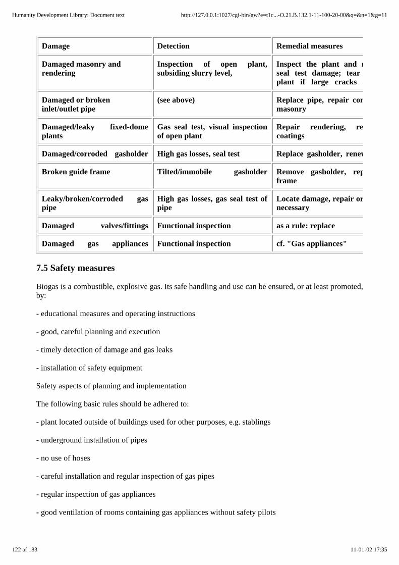
Damage Detection Remedial measures
Damaged masonry andrendering
Inspection of open plant,subsiding slurry level,
Inspect the plant and repairseal test damage; tearplant if large cracks are
Damaged or brokeninlet/outlet pipe
(see above) Replace pipe, repair connectionmasonry
Damaged/leaky fixed-domeplants
Gas seal test, visual inspectionof open plant
Repair rendering, renewcoatings
Damaged/corroded gasholder High gas losses, seal test Replace gasholder, renew
Broken guide frame Tilted/immobile gasholder Remove gasholder, repairframe
Leaky/broken/corroded gaspipe
High gas losses, gas seal test ofpipe
Locate damage, repair ornecessary
Damaged valves/fittings Functional inspection as a rule: replace
Damaged gas appliances Functional inspection cf. "Gas appliances"
7.5 Safety measures
Biogas is a combustible, explosive gas. Its safe handling and use can be ensured, or at least promoted,by:
- educational measures and operating instructions
- good, careful planning and execution
- timely detection of damage and gas leaks
- installation of safety equipment
Safety aspects of planning and implementation
The following basic rules should be adhered to:
- plant located outside of buildings used for other purposes, e.g. stablings
- underground installation of pipes
- no use of hoses
- careful installation and regular inspection of gas pipes
- regular inspection of gas appliances
- good ventilation of rooms containing gas appliances without safety pilots
122 af 183 11-01-02 17:35
Humanity Development Library: Document text http://127.0.0.1:1027/cgi-bin/gw?e=t1c...-O.21.B.132.1-11-100-20-00&q=&n=1&g=11
- installation of safety stop valves
- one directly on the plant, and another on each appliance.
Educational measures and operating instructions
The user must be made fully aware of the explosive nature of biogas, possibly by way ofdemonstration (e.g. by producing a flash flame). He must learn by heart the following basic rules:
- Never leave an open flame unattended!
- Always close the gas and safety valves of each appliance properly and immediately after each use!
- Close the plant's safety valves each night and whenever the plant is left unattended!
Experience shows that leaks and open gas cocks can be detected very quickly, i.e. before anexplosive mixture forms, by watching for the conspicuous odor of unburned biogas.
Safety devices
As long as the above safety aspects are adhered to, small biogas plants in rural areas require few orno special safety devices, the one major exception being appliances that operate on their own, i.e.refrigerators, radiant heaters, etc., in which case the use of safety pilots is obligatory.
8. Economic analysis and socioeconomic evaluation
8.1 Procedures and target groups
Any decision for or against the installation and operation of a biogas plant depends on varioustechnical criteria as well as on a number of economic and utility factors. The quality and relevance ofthose factors are perceived differently, depending on the respective individual intrest:
- Users want to know what the plant will offer in the way of profits (cost-benefit analysis) and otheradvantages like reduced workload, more reliable energy supplies or improved health and hygiene(socioeconomic place value).
- Banks and credit institutes are primarily interested in the economic analysis as a basis for decisionswith regard to plant financing.
- Policy-makers have to consider the entire scope of costs and benefits resulting from introductionand dissemination, since their decisions usually pertain to biogas extension programs instead of toindividual plants.
123 af 183 11-01-02 17:35
Humanity Development Library: Document text http://127.0.0.1:1027/cgi-bin/gw?e=t1c...-O.21.B.132.1-11-100-20-00&q=&n=1&g=11

Fig. 8.1: Basic elements of an economic analysis (Source: OEKOTOP)
The evaluation of biogas plants must include consideration not only of the monetary cost/ benefitfactors, but also of the ascertainable nonpecuniary and unquantifiable factors. Time and again,practical extension work with the owners of small and medium-sized farms shows that a purelymonetary approach does not reflect the farmers' real situation. For a farmer who thinks and works interms of natural economic cycles, knowing how many hours of work he stands to save is often moreimportant than knowing how much money he stands to gain. A similar view is usually taken of theoften doubtful monetary evaluation of such a plant's qualitative and socioeconomic impact.
Figure 8.1 surveys the essential parts of an economic analysis. In practice, however, the collecting ofinformation and data can present problems: experience shows, for example, that an exact breakdownof cost and benefits can hardly be arrived at until the plant has been in service long enough for theuser to have gained some initial experience with its operation. Economic prognoses therefore shouldgive due regard to such limitations by including calculations for various scenarios based onpessimistic, average-case and optimistic assumptions. Consequently, the data stated in the followingcalculations and considerations are intended to serve only as reference values. Any attempt to convertlocal plant & equipment costs into DM-values is seriously complicated by the fact that exchangerates are often set more or less arbitrarily and that the figures used may derive from unstableblack-market prices.
8.2 Working-time balance
For the users of family-size plants - primarily the operators of small to medium-size farms - thefollowing three elements of the biogas plant evaluation have the most relevance:
124 af 183 11-01-02 17:35
Humanity Development Library: Document text http://127.0.0.1:1027/cgi-bin/gw?e=t1c...-O.21.B.132.1-11-100-20-00&q=&n=1&g=11
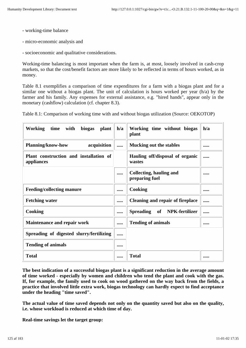
- working-time balance
- micro-economic analysis and
- socioeconomic and qualitative considerations.
Working-time balancing is most important when the farm is, at most, loosely involved in cash-cropmarkets, so that the cost/benefit factors are more likely to be reflected in terms of hours worked, as inmoney.
Table 8.1 exemplifies a comparison of time expenditures for a farm with a biogas plant and for asimilar one without a biogas plant. The unit of calculation is hours worked per year (h/a) by thefarmer and his family. Any expenses for external assistance, e.g. "hired hands", appear only in themonetary (cashflow) calculation (cf. chapter 8.3).
Table 8.1: Comparison of working time with and without biogas utilization (Source: OEKOTOP)
Working time with biogas plant h/a Working time without biogasplant
h/a
Planning/know-how acquisition ..... Mucking out the stables .....
Plant construction and installation ofappliances
Hauling off/disposal of organicwastes
.....
..... Collecting, hauling andpreparing fuel
.....
Feeding/collecting manure ..... Cooking .....
Fetching water ..... Cleaning and repair of fireplace .....
Cooking ..... Spreading of NPK-fertilizer .....
Maintenance and repair work ..... Tending of animals .....
Spreading of digested slurry/fertilizing .....
Tending of animals .....
Total ..... Total .....
The best indication of a successful biogas plant is a significant reduction in the average amountof time worked - especially by women and children who tend the plant and cook with the gas.If, for example, the family used to cook on wood gathered on the way back from the fields, apractice that involved little extra work, biogas technology can hardly expect to find acceptanceunder the heading "time saved".
The actual value of time saved depends not only on the quantity saved but also on the quality,i.e. whose workload is reduced at which time of day.
Real-time savings let the target group:
125 af 183 11-01-02 17:35
Humanity Development Library: Document text http://127.0.0.1:1027/cgi-bin/gw?e=t1c...-O.21.B.132.1-11-100-20-00&q=&n=1&g=11
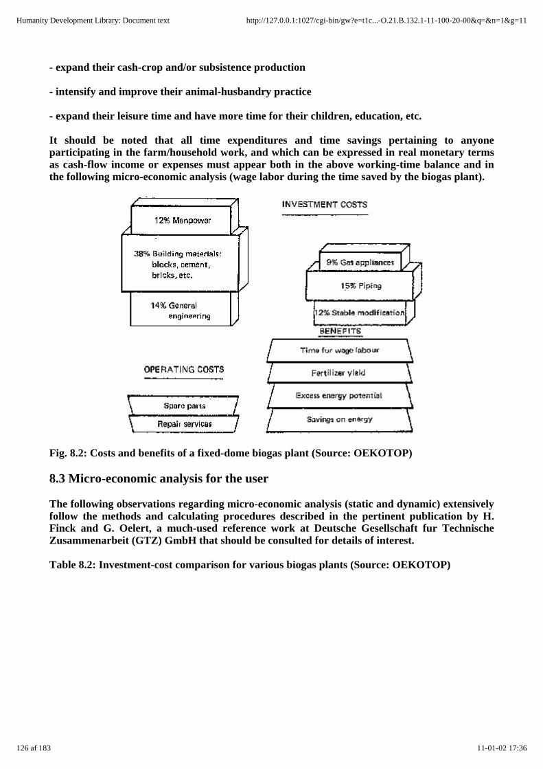
- expand their cash-crop and/or subsistence production
- intensify and improve their animal-husbandry practice
- expand their leisure time and have more time for their children, education, etc.
It should be noted that all time expenditures and time savings pertaining to anyoneparticipating in the farm/household work, and which can be expressed in real monetary termsas cash-flow income or expenses must appear both in the above working-time balance and inthe following micro-economic analysis (wage labor during the time saved by the biogas plant).
Fig. 8.2: Costs and benefits of a fixed-dome biogas plant (Source: OEKOTOP)
8.3 Micro-economic analysis for the user
The following observations regarding micro-economic analysis (static and dynamic) extensivelyfollow the methods and calculating procedures described in the pertinent publication by H.Finck and G. Oelert, a much-used reference work at Deutsche Gesellschaft fur TechnischeZusammenarbeit (GTZ) GmbH that should be consulted for details of interest.
Table 8.2: Investment-cost comparison for various biogas plants (Source: OEKOTOP)
126 af 183 11-01-02 17:36
Humanity Development Library: Document text http://127.0.0.1:1027/cgi-bin/gw?e=t1c...-O.21.B.132.1-11-100-20-00&q=&n=1&g=11

Cost factor Water-jacket.Plant
Fixed-dome plant Plastic-sheet plant
Cost per m³ digester(DM)
200-400 150 - 300 80-120
including:Gasholder 23 % (part of digester) 8%
Digester/slurry store 35% 50% 42%
Gas appliances/piping 22% 24% 36%
Stable modification 8% 12% -
General engineering 12% 14% 14%
Surrey of the monetary costs and benefits of a biogas plant
Figure 8.2 shows a breakdown of the basic investment-cost factors for a - presumedly -standardized fixed-dome plant. The cost of material for building the digester, gasholder anddisplacement pit (cement, bricks, blocks) can, as usual, be expected to constitute the biggest costitem. At the same time, the breakdown shows that the cost of building the plant alone, i.e.without including the peripherals (animal housing, gas appliances, piping) does not give a clearpicture.
For a family-size plant, the user can expect to pay between 80 and 400 DM per m³ digestervolume (cf. table 8.2). This table shows the total-cost shares of various plant components fordifferent types of plant. While the average plant has a service life of 10-15 years, other costsmay arise on a recurrent basis, e.g. painting the drum of a floating-drum plant and replacing itafter 4 - 5 years. Otherwise, the operating costs consist mainly of maintenance and repair workneeded for the gas piping and gas appliances. At least 3% of the initial investment costs shouldbe assumed for maintenance and repair.
The main benefits of a biogas plant are:
- savings attributable to less (or no) consumption of conventional energy sources for cooking,lighting or cooling
- the excess energy potential, which could be commercially exploited
- substitution of digested slurry in place of chemical fertilizers and/or financially noticeableincreases in crop yields
- savings on time that can be used for wage work, for example.
Usually, a biogas plant will only be profitable in terms of money if it yields considerable savingson conventional sources of energy like firewood, kerosene or bottled gas (further assuming thatthey are not subsidized).
Financially effective crop-yield increases thanks to fertilizing with digested slurry are hard toquantify, i.e. their accurate registration requires intensive observation of the plant's operatingparameters.
127 af 183 11-01-02 17:36
Humanity Development Library: Document text http://127.0.0.1:1027/cgi-bin/gw?e=t1c...-O.21.B.132.1-11-100-20-00&q=&n=1&g=11

Such limitations make it clear that many biogas plants are hardly profitable in monetary terms,because the relatively high cost of investment is not offset by adequate financial returns.Nonetheless, if the user considers all of the other (non-monetary) benefits, too, he may well findthat operating a biogas plant can be worth his while. The financial evaluation (micro-economicanalysis), the essential elements of which are discussed in the following chapter, thereforecounts only as one of several decision-making instruments to be presented to the potential user.
The main advisory objective is to assess the user's risk by calculating the payback period("How long will it take him to get back the money he invested?") and comparing it with thetechnical service life of the plant. Also, the user must be given some idea of how much interesthis capital investment will carry (profitability calculation).
The micro-economic analytical methods described in the following subsections require thehighest achievable accuracy with regard to the identification of costs and benefits for the biogasplant under consideration. Chapter 10.4 in the appendix includes an appropriate formsheet fordata collection. With a view to better illustrating the described analytical methods, theformsheet (table 10.10) includes fictive, though quite realistic, data concerning a familysizebiogas plant. Those data are consistently referred to and included in the mathematical modelsfor each of the various sample analyses.
Calculation of the static payback period according to the cumulative method (data taken fromthe appendicized formsheet, table 10.10).
Input parameters:
- investment costs
- annual revenues
- less the yearly operating costs
- less the external capital costs
= annual returns
The cumulative method allows consideration of different annual returns.
Calculatory procedure: The investment expenditures and annual returns are added togetheruntil the line-3 total in table 8.3 either reaches zero (end of payback period) or becomespositive.
Evaluation: As far as risk minimization is concerned, a short payback period is very valuablefrom the standpoint of the plant's user ("short" meaning significantly less than 10 years, thedata listed in table 8.3 pegs it at 5.5 years). Should the analysis show a payback period of 10years or more, thus possibly even exceeding the technical service life of the plant, building theplant could not be recommended unless other important factors are found to outweigh thatdisadvantage.
128 af 183 11-01-02 17:36
Humanity Development Library: Document text http://127.0.0.1:1027/cgi-bin/gw?e=t1c...-O.21.B.132.1-11-100-20-00&q=&n=1&g=11

Table 8.3: Schedule of data for calculating the plant payback period (with case example; datataken from the appendicized formsheet, table 10.l0) (Source: OEKOTOP)
Static calculation of profitability (data taken from table 10.10 in the Appendix)
Input parameters:
- average capital invested per time interval, KA
- net profit, NP = annual return
- less the external capital servicing costs
- less the depreciation
Calculatory procedure: The profitability, or return on investment, ROI, is calculated accordingto the following formula
The linear annual depreciation amounts to:
The technical service life of a biogas plant generally amounts to 10-15 years. It is advisable tocalculate twice, one for a pessimistic assumption (10-year service life) and once for anoptimistic assumption (15-year service life). Similarly, the net profit should also be variedunder pessimistic and optimistic assumptions.
Evaluation: The user can at least expect the biogas plant to yield a positive return on hisinvested capital. The actual interest should be in the range of locally achievable savings-accountinterest. Also, the results of profitability calculation can be used to compare the financialquality of two investment alternatives, but only if their respective service lives and investmentvolumes are sufficiently comparable.
Calculating the profitability using the appendicized data
Initial investment, Io = 1100
129 af 183 11-01-02 17:36
Humanity Development Library: Document text http://127.0.0.1:1027/cgi-bin/gw?e=t1c...-O.21.B.132.1-11-100-20-00&q=&n=1&g=11
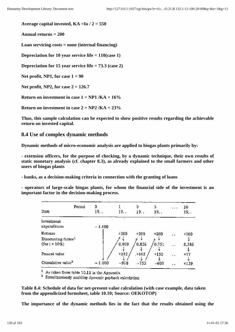
Average capital invested, KA =Io / 2 = 550
Annual returns = 200
Loan servicing costs = none (internal financing)
Depreciation for 10 year service life = 110(case 1)
Depreciation for 15 year service life = 73.3 (case 2)
Net profit, NP1, for case 1 = 90
Net profit, NP2, for case 2 = 126.7
Return on investment in case 1 = NP1 /KA = 16%
Return on investment in case 2 = NP2 /KA = 23%
Thus, this sample calculation can be expected to show positive results regarding the achievablereturn on invested capital.
8.4 Use of complex dynamic methods
Dynamic methods of micro-economic analysis are applied to biogas plants primarily by:
- extension officers, for the purpose of checking, by a dynamic technique, their own results ofstatic monetary analysis (cf. chapter 8.3), as already explained to the small farmers and otherusers of biogas plants
- banks, as a decision-making criteria in connection with the granting of loans
- operators of large-scale biogas plants, for whom the financial side of the investment is animportant factor in the decision-making process.
Table 8.4: Schedule of data for net-present-value calculation (with case example, data takenfrom the appendicized formsheet, table 10.10; Source: OEKOTOP)
The importance of the dynamic methods lies in the fact that the results obtained using the
130 af 183 11-01-02 17:36
Humanity Development Library: Document text http://127.0.0.1:1027/cgi-bin/gw?e=t1c...-O.21.B.132.1-11-100-20-00&q=&n=1&g=11
simpler static methods of calculation described in chapter 8.3 can become problematic, if thepoint in time at which payments become due is of increasing importance. Any investornaturally will set a lower valuation to revenues that are due a decade from now than to thosewhich are coming in at present. Consequently, he would want to compound past payments anddiscount future payments to obtain their respective present values.
Net-present-value method
The most commonly employed method of dynamic micro-economic analysis is thenet-present-value method used by many extension officers. It enables evaluation of both theabsolute and relative advantages of a biogas-plant investment (as compared to other investmentalternatives) on the basis of the anticipated minimum interest rate above and beyond the netpresent value of the investment. Simultaneously, the netpresent-value method also serves as abasis for calculating the dynamic payback period and for calculations based on the annuitiesmethod. (For details on the net-present-value and other dynamic methods of calculation, pleaserefer to the aforementioned publication by Finck/Oelert.)
The inflation problem: Either the entire calculation is based on nominal incomes andexpenditures, and market interest rates (= calculatory interest) are assumed, or the income andexpenditures are presumed to remain constant, and the calculation is based on the real interestrate. The latter is calculated according to the following formulae (p = market rate of interestand a = rate of inflation):
Example: market rate of interest = 48%; rate of inflation = 34%
i = [(100 + 48)/(100 +34)]* 100-100=10.4%
Discounting factors: The compounding and discounting factors for the net-present-valuemethod are shown in table 10.11 (Appendix) for interest rates of 1-30% and service lives of 1-15years.
Calculatory procedure: The following information is drawn from the appendicized datasurvey: calculatory rate of interest, i (item 1.3); investment costs, I (item 2) and the returns(item 8). Much like the static mathematical models discussed in chapter 8.3, the calculatoryprocedures are again made more readily understandable by inserting the appropriate datafrom the formsheet (table 10.10, Appendix). In a real case, those data naturally would have tobe replaced by the actual on-site data.
Results: The biogas plant can be regarded as profitable, if its net present value is found to beequal to or greater than zero for the minimum acceptable interest rate, e.g. i= 10%. The netpresent value is arrived at by cumulating the cash-flow value. Among several alternativeinvestments, the one with the highest net present value should be chosen.
Sample calculation: For a plant service life of 10 years (conservative estimate), the cash flowvalues reflecting the annual returns times the discounting factor need to be determined andcumulated (cf. table 8.4). In this example, the net present value, at 129, would be positive, i.e.the potential investment would be worthwhile. The effects of discounting future income to itspresent value are substantial. For example, the return listed as 200 in item 10 would have acash-flow value of 77 for a calculatory interest rate of 10°,to.
8.5 Qualitative evaluation by the user
131 af 183 11-01-02 17:36
Humanity Development Library: Document text http://127.0.0.1:1027/cgi-bin/gw?e=t1c...-O.21.B.132.1-11-100-20-00&q=&n=1&g=11

Biogas plants have numerous direct and indirect advantages - and, under certaincircumstances, disadvantages - that cannot be expressed in terms of money, but which can bevery important for the user. Even when a biogas plant is not financially profitable, meaningthat it costs the user more than it yields, it can still have such a high socioeconomic value as towarrant its installation. Table 8.5 lists the essential socioeconomic biogas-plant evaluationfactors, including plus, neutral and minus symbols to allow individual-aspect evaluation.
Table 8.5: Socioeconomic benefits and drawbacks of biogas production and utilization (Source:OEKOTOP)
Benefits Possible drawbacks
Assured, regular supply of energyrating: + o -
Direct handling of fecesrating: + o -
Improved hygienic conditions through Limited communicationpotential, e.g. no
better disposal of feces, no smokycooking fires, less nuisance from fliesrating: + o -
more gathering of woodtogether rating: + o -
General improvement of the agriculturalproduction conditions, e.g. better livestock hygine/care, improved soilstructure
rating: + o -
Upgrading of women's work
rating: + o -
Better lighting
rating: + o -
Higher prestige
rating: + o -
+ applicable o possibly applicable - not applicable
8.6 Macro-economic analysis and evaluation
The main quantifiable macro-economic benefits are:
- national energy savings, primarily in the form of wood and charcoal, with the latter being valued atmarket prices or at the cost of reforestation
- reduced use of chemical fertilizers produced within the country.
132 af 183 11-01-02 17:36
Humanity Development Library: Document text http://127.0.0.1:1027/cgi-bin/gw?e=t1c...-O.21.B.132.1-11-100-20-00&q=&n=1&g=11

Additionally, foreign currency may be saved due to reduced import of energy and chemical fertilizers.
Macro-economic costs incurred in local currency for the construction and operation of biogas plantsinclude expenditures for wages and building materials, subsidy payments to the plant users, theestablishment of biogas extension services, etc. Currency drain ensues due to importing of gasappliances, fittings, gaskets, paints, etc.
In addition to such quantifiable aspects, there are also qualitative socioeconomic factors that gainrelevance at the macroeconomic level:
- autonomous decentralized energy supply
- additional demand for craftsmen's products (= more jobs)
- training effects from exposure to biogas technology
- improved health & hygienic conditions, etc.
Considering the present extent of biogas-plant diffusion, such effects should be viewed realistically,i.e. not overvalued. While a substantial number of biogas plants may be installed in one or moreregions of a given developing country, they cannot be expected to have much impact at the nationallevel. At the regional and local levels, however, the multipartite effects described in this subsectionare definitly noticeable.
9. Social acceptance and dissemination
In many cases, the successful commissioning of a few biogas plants generates a keen demand formore plants among local farmers and other interested parties. Consequently, the responsibleextension officer often sees himself confronted with the prospect of planning and building moreplants. However, before any decision is made in favor of launching a biogas extension program, theextension officer should make an additional detailed analysis of all positive and negative informationconcerning experience to date with the plants that have already been built. Only if the results soindicate, should he decide to engage in further building and dissemination activities.
9.1 Determining factors of acceptance for biogas plants
On the whole, the question of acceptance covers all aspects of biogas technology discussed in thisbook (agriculture, engineering/ construction, operation and maintenance, economic viability). Inorder to avoid redundancy, this chapter is therefore limited to a discussion of general aspects thathave not yet been accounted for.
Biogas extension efforts should include special consideration of the role played by women, since it isthey and their children who perform much of the important work needed to keep a biogas plantrunning. This includes tending cattle, collecting substrate, fetching water, operating gas appliances,cooking, spreading digested slurry, etc. In many cultures, however, they are by tradition hardlydirectly involved in the process of decision making, e.g. the decision "biogas plant: yes/no and how".Nor are they often allowed for in connection with external project planning. In other regions, though,e.g. many parts of West Africa, women are economically independent of their husbands, i.e. theyhave their own fields, animals and farm-produce marketing channels.
Extension officers charged with planning and building biogas plants often have little or no awarenessof the specific local and regional social conventions. Thus, the promotion of participation, thearticulation of user interests, and the involvement of local extension workers are all very importantfor doing them at least some degree of justice.
133 af 183 11-01-02 17:36
Humanity Development Library: Document text http://127.0.0.1:1027/cgi-bin/gw?e=t1c...-O.21.B.132.1-11-100-20-00&q=&n=1&g=11

In general, a general willingness to accept the construction and operation of biogas plants can beexpected and/or can be increased by:
Planning/project organization
- involving the users, especially the women, in all decisions concerning "their" biogas plant
- coordinating all essential program measures with target group representatives
- keeping the user/target group informed
- establishing trustworthy, reliable implementing agency;
Sociocultural
- existing willingness to handle feces and gas
- identicality of users (beneficiaries) and operators of the respective biogas plants
- positive image of biogas technology, or image polishing through biogas plants;
Engineering/construction
- well-functioning, durable and good-looking plants from the very start
- availability of well-functioning, inexpensive, modern gas appliances (burners, lamps, refrigerators,etc.)
- user friendliness of plants and appliances
- guaranteed supply of materials and spare parts and assured repair and maintenance;
Agriculture
- stabling practice or tendency toward such practice
- effective time savings, e.g. by direct connection of the biogas plant to the barn
- willingness to use digested slurry as fertilizer, knowledge of storage and spreading techniques, andappreciation of the positive effects of fertilizing
- availability of suitable, inexpensive slurry spreading implements;
Economy
- reasonable expense in terms of money and work involved (as viewed from the user's standpoint)
- real and, for the user, obviously positive cost-bereft ratio (not necessarily just in terms of money)
- favorable financing(loans,subsidies),
Household advantages
134 af 183 11-01-02 17:36
Humanity Development Library: Document text http://127.0.0.1:1027/cgi-bin/gw?e=t1c...-O.21.B.132.1-11-100-20-00&q=&n=1&g=11

- improved working conditions in the kitchen (less smoke and flies, better appearance,modernization)
- introduction or improvement of artificial lighting
- effective workload reduction
- complete, reliable supply of energy through biogas.
It is very important that the biogas extension officer seek intensive contact with the potential plantusers and local decision makers in order to maximize the chance of early detection of any deficitsregarding the acceptance of biogas technology in order to promptly modify and improve the projectstrategy as necessary.
9.2 Dissemination strategies
Ideally, there are two basic strategies for disseminating family-size biogas plants (cf. table 9.1). Theoriginal "classic" approach to biogas dissemination - the self-helporiented approach - has in manyregions now taken a backseat to the newer professional-artisan approach. While the "do-ityourself7'approach has the advantage of reaching target groups with relatively little capital and of beingapplicable in regions with a few or more scattered biogas plants, recent project experience has shownthat the professional-artisan strategy leads to a faster and numerically more substantial process ofdissemination (once the artisans have been adequately familiarized with the work involved) and thatit does more to promote self-supporting local structures.
Since biogas technology is still regarded as "something new" in most developing regions - eventhough some pilot plants may already be in operation - the extension officer must very carefully studythe regional preconditions for a successful approach to biogas dissemination. This involves gettinganswers to the following questions:
- What kind of infrastructure does the region have in the way of roads, highways, means oftransportation, etc.? The biogas dissemination concept and its timetable must be designed to conformto the given situation.
- How much of the required material is locally available? How much locally unavailable material canbe imported without difficulty? Naturally, as much locally available material as possible should beused for building, maintaining and repairing the plants.
Table 9.1: Biogas dissemination strategies (ideal case) (Source: OEKOTOP)
135 af 183 11-01-02 17:36
Humanity Development Library: Document text http://127.0.0.1:1027/cgi-bin/gw?e=t1c...-O.21.B.132.1-11-100-20-00&q=&n=1&g=11

A. Professional-artisan approach B. Self-help-oriented approach
Dissemination of "turnkey"biogas plants, primarily throughprofessional artisans
Motivated, interested users do part of theconstruction work
Preconditions: Preconditions:
Adequate capital on the part ofthe owners/users
Willingness to contribute own efforts (building,main tenance, etc.)
Motivated, qualifiable artisans User training is highly relevant
High plant density with goodincome prospects for the artisans
Government or development aid assumes partof the cost for low-income users
Good supply of materials to theartisans, possibly throughcooperation between the stataland private sectors; statal sectorfunctions as source of know-how
Well-organized biogas project with adequatepresence (despite low plant density) for givingadvice, helping to build the plants, and offeringtechnical solutions for a wide diversity of tasksituations
Measures: Measures:
Offering a complete biogasplant, i.e. a standardized, testedtype of plant of a size adequateto the needs of the user,including gas appliances
Offering both standard-type systems andsolutions for special problems; reaching out toremote areas
Repair and supply of spare partsby and through local artisans
The project provides the plant elements thatcan't be built by the users themselves
Qualification of local artisans forplanning, building and repairingstandardized biogas plants
In addition to local artisans, the usersthemselves are given training in building,repair and maintenance
Cost reduction throughstandardization
The project secures locally unavailablematerials
Provision of assistance to the user in the formof subsidies/loans
Table 9.2: Innovation cycle of biogas dissemination (Source: OEKOTOP)
Regional studies/target groups (ethnological, socioeconomic)
Market analysis (biomass potential, energy demand, purchasing power, market potential, priorstate of development, biogas technique, suppliers)
Analysis of implementation (general make-up and organizational structure, finances, personnelqualifications, relation to target group(s)/regional anchorage, political weight)
136 af 183 11-01-02 17:36
Humanity Development Library: Document text http://127.0.0.1:1027/cgi-bin/gw?e=t1c...-O.21.B.132.1-11-100-20-00&q=&n=1&g=11

Formulation of concept
R & D phase, development and adaptation of suitable type of plants to accommodate differentareas of service
Installation and operation of pilot plants
Establishment of local partners (artisans, self-help organizations)
Familiarization and training of users, artisans, engineers/planners, advisors, financinginstitutions, political decision-makers, Media/means: workshops, on-the-job training, handbills,manuals, demonstration models, pictorial material, radio, television
Continuous improvement and sophistication of solutions found (technology, disseminationstrategy, organization)
- Are enough adequately qualified and motivated extension workers and craftsmen readilyavailabe?
- Is there an implementing agency with adequate performance potential and access to the futureplant users, thus providing a basis for mutual-thrust cooperation?
Ascertainment of the extent to which the above preconditions are either being met already orcould be satisfied through appropriate measures is part of the "biogas innovation cycle"outlined in table 9.2.
9.3 Implementing agencies
As a rule, biogas programs are implemented by national, state or parastatal institutions. Asdetailed in chapter 9.4, construction is done by artisans.
In selecting a implementing agency, it is advisable to consider the criteria listed in table 9.3 as abasis for evaluating the qualifications of the implementing agency.
This catalogue can be used to examine existing project partners for real or potentialshortcomings with regard to biogas-related task accomplishments with a view to helping themreorganize in order to better handle the job at hand.
Table 9.3: Catalogue of attributes for partners in biogas dissemination projects (Source:OEKOTOP)
Legal form/institutional category (ministry, bank, research institute, rural developmentinstitution, etc.)
Work scopes/specialties
- experience with biogas and other renewable energy systems
- experience in rural development
Institutional action principle (break-even operation, maximization of profits, heavy dependenceon subsidies)
Managerial organization
137 af 183 11-01-02 17:36
Humanity Development Library: Document text http://127.0.0.1:1027/cgi-bin/gw?e=t1c...-O.21.B.132.1-11-100-20-00&q=&n=1&g=11

- organizational structure (entrenched hierarchy? teamwork? codetermination?)
- classification and-institutional significance of the biogas program within the executingorganization
- institutional flexibility
Staff endowment for the biogas project - number and qualifications (special emphasis onagricultural engineers, farmers, technicians, social economists, masons and plumbers, officeworkers/administrators) - training offered or possible - wage and salary structure - fluctuation,migration
Sundry institutional appointments
- office space, vehicles, telephone, teletex, workshops
- financial endowment of the biogas project (for personnel, transportation, materials and spareparts, public relation
activities, etc.)
- potential for providing complementary services in connection with biogas (financing, technicaland socioeconomic
consultancy, maintenance & repair services, etc.)
Interest in the biogas project
- own commercial interest in biogas
- connection with and proximity to the target group and/or to artisans, probability of targetgroup participation
- chances of implementing a national or regional biogas extension program
- domestic importance/prevailing power
Table 9.4: Institutional breakdown of biogas-dissemination tasks and activities (applies inparticular to the professional-artisan approach discussed in chapter 9.2) (Source: OEKOTOP)
138 af 183 11-01-02 17:36
Humanity Development Library: Document text http://127.0.0.1:1027/cgi-bin/gw?e=t1c...-O.21.B.132.1-11-100-20-00&q=&n=1&g=11
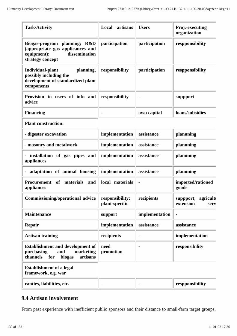
Task/Activity Local artisans Users Proj.-executingorganization
Biogas-program planning; R&D(appropriate gas applicances andequipment); disseminationstrategy concept
participation participation respponsibility
Individual-plant planning,possibly including thedevelopment of standardized plantcomponents
responsibility participation respponsibility
Provision to users of info andadvice
responsibility - suppport
Financing - own capital loans/subsidies
Plant construction:
- digester excavation implementation assistance plannning
- masonry and metalwork implementation assistance plannning
- installation of gas pipes andappliances
implementation assistance plannning
- adaptation of animal housing implementation assistance plannning
Procurement of materials andappliances
local materials - imported/rationedgoods
Commissioning/operational advice responsibility;plant-specific
recipients suppport; agriculturalextension services
Maintenance support implementation -
Repair implementation assistance assistance
Artisan training recipients - implementation
Establishment and development ofpurchasing and marketingchannels for biogas artisans
needpromotion
- responsibility
Establishment of a legalframework, e.g. war
ranties, liabilities, etc. - - respponsibility
9.4 Artisan involvement
From past experience with inefficient public sponsors and their distance to small-farm target groups,
139 af 183 11-01-02 17:36
Humanity Development Library: Document text http://127.0.0.1:1027/cgi-bin/gw?e=t1c...-O.21.B.132.1-11-100-20-00&q=&n=1&g=11

many biogas projects strive to coordinate the activities of private businesses and govermental projectorganisations through:
- local-scale biogas dissemination work by involving local artisans through personal~ initiative andcustomer orientation
- securing the political and organizational framework through regional/supraregional state/parastatesponsors.
The main objective of providing assistance to artisans in connection with biogas projects is to buildup self-supporting local structures and promote the formation of regional business cycles with theappropriate effects on technological innovation, employment and income. An efficient form of biogasdissemination, i.e. one based on a good cost/ benefit ratio, is envisaged.
Nonetheless, the following points should be heeded when trying to get local artisans involved in theprocess of biogas dissemination:
- How many qualified craftsmen (masons, welders, plumbers, etc.) are available for work on theproject and/or in the villages? To the extent possible, the biogas extension officer should rely onartisans who live and work within the project area.
- How much interest do the artisans have in the project, and how well-motivated are they? What aretheir expectations regarding income? What is the least number of plants that have to be built in orderto guarantee a craftsman a full income or at least a satisfactory sideline income?
- How many and what kind of tools and implements do the artisans have and need? How can thelacking equipment be financed?
Important workscopes for artisans
Depending on the local situation, the artisans' workscopes and competences can vary substantiallyfrom place to place. Still, a general breakdown of task scopes can be drawn up for the localcraftsmen, the biogas project, the official implementing agency and the user when it comes toplanning and operating a biogas plant (cf. table 9.4). The biogas artisans are generally responsible forthe following tasks:
- detailed planning of plants for individual sites (presupposing the availability of standardized ormodular plant components that are adequate for the situation and can be installed with no substantialdegree of modification at any suitable site)
- providing advisory services and information to the users
- all work in connection with building and starting the plant, from the digester excavation to themasonry and plumbing - for which the requisite tools and materials must be procured
- any necessary maintenance and repair work.
Both the quality standards for the work to be done and the success of the biogas dissemination effortsare heavily dependent on the presence of qualified craftsmen, particularly masons, in the projectregion.
9.5 Training
The training measures address different target groups, each with their own specific training contents
140 af 183 11-01-02 17:36
Humanity Development Library: Document text http://127.0.0.1:1027/cgi-bin/gw?e=t1c...-O.21.B.132.1-11-100-20-00&q=&n=1&g=11

and methods (cf. table 9.5):
- the engineers and extension officers, who are to do the planning and assume advisory duties
- the artisans, who are to build the plants and keep them in repair
- the owners, who require qualification for operating the plants efficiently and,possibly, know-howfor performing at least some of the building, maintenance and repair work on their own.
The following items require consideration in connection with biogas training measures:
- Training courses and training material must be held/written in the national or regional language.
- The training material must correspond to the specific targetgroup situation, e.g. experience has beengood with loose-leaf material that can be compiled and revised as necessary to fit the needs of eachparticular target group.
- The demonstration models must agree with the types of plant actually proposed, i.e. do not dry toexplain the abstract principle of an oil-drum model or put a fixed-dome on display, whenfloating-drum plants are supposed to be installed.
- A great deal of practical training must be provided. Positive experience has been made withintegrated workshops in which theoretical training is combined with hands-on experience in theconstruction of a real plant.
- Women must be included in the training measures.
Supraregional workshops, even going beyond the country's borders (allowing the exchange ofexperience from country to country) are a worthwhile training device for engineers, extension officersand, to some extent, artisans. Training/attendance certificates are recommended as a means ofdeveloping training standards and motivating trainees to participate in the courses offered.
Table 9.5: Target-group-oriented biogas training measures (Source: OEKOTOP)
141 af 183 11-01-02 17:36
Humanity Development Library: Document text http://127.0.0.1:1027/cgi-bin/gw?e=t1c...-O.21.B.132.1-11-100-20-00&q=&n=1&g=11

Target group Training elements Contents Duration Instructor
Engineers,localextensionofficers
Seminars and fieldtrips, nationalworkshops, supra-regionalconferences servingto effect technologytransfer
Function of varioustypes of biogasplants andperipheralequipment, use ofdigested slurry,maintenance andrepair problems,macro- andmicroeconomicanalysis/evaluation,project management
several blocks ofapprox. 1 week each
biogasagriculturalsocial economists
Artisans Integratedworkshops withtheoretical +practical training,incl. On- the-jobtraining (OJT)
Function of selectedtypes of plants,design andconstruction perdrawing, use of localmaterials,maintenance &repair
workshops lastingseveral days,participation in plantconstruction
engineers,artisans
Users Field trips tooperable plants,participation inworkshopsOn-the-spottraining (ownplant)
Function of selectedtypes of plants,operation andoptimal use,fertilizing withdigested slurry,maintenance &repair
2-3 days, regular on-site back- stopping
local biogas/agriculturalworkers
Women On-the-spottraining (ownplant), localevening courses
Plant function,operation andoptimal use,working with biogascookers
continuousfamiliarization(women!)
localworkers
9.6 Financing
Small farmers in particular rarely have the DM 1000 - 2500 or more it takes to cover the cost of abiogas plant. Consequently, "mixed-financing models" with the three elements owncapital/contribution, subsidy and loan must be available.
Own capital/contribution
While a potential user may not be able to fully finance a biogas plant by himself, he must be expectedto carry at least 30 - 40% of the initial outlay, possibly in the form of contributed work like digesterexcavation, procuring building materials, etc.
Subsidies
142 af 183 11-01-02 17:36
Humanity Development Library: Document text http://127.0.0.1:1027/cgi-bin/gw?e=t1c...-O.21.B.132.1-11-100-20-00&q=&n=1&g=11

The economic benefits of a biogas plant can be quite modest, e.g. when it serves as a substitute forwood that can be gathered for free. The overall benefits, however, including such environmentalfactors as the protection of forests, can be very substantial. Consequently, the user of the plant shouldbe eligible for subsidies to make up the difference. Such subsidies may consist of:
- contributions to the cost of construction in the form of needed materials (metal gasholder, cement,fittings, etc.), such frequently scarce goods and materials also including those needed for repairs andreplacements, e.g. rustproofing for the gasholder,
- free planning and consulting
- assumption of interest debt on loans.
On the whole, however, subsidies have the following drawbacks:
- Market prices can become distorted, and needed capital can be falsely invested.
- Subsidies intended explicitly for the needy may end up in the hands of well-todo groups.
In addition, prior project experience has shown that user motivation is frequently lower in the case ofheavily subsidized plants than in the case of plants that have been evaluated and built on acommercial basis.
Loans
The monetary returns from a biogas plant, particularly those from a small family-size one, are oftenmeagre in comparison to the cost of investment. In other words, the plant hardly pays for itself interms of real income. Additionally, since most small farmers have no access to commercial loans, butshould not be expected to accept an excessive risk of indebtedness, it can be quite difficult to arrangebiogas-plant credit financing for that group of users. The following conditional factors thereforeshould be investigated prior to setting up any particular credit program:
- first, check out all other funding alternatives, e.g. owned capital;
- then, conduct a detailed socioeconomic analysis of the target group and farms, e.g. which farm canafford how much debt burden?;
- next, clarify the institutional tie-in, i.e. involvement of rural development banks or credit unions;
- and, lastly, establish the program quality, e.g. isolated or integrated credit programs, the latterincluding technical and economic extension services, training, plant maintenance and repair.
If the appraisal shows that there is available within the region a credit program that is open to thefinancing of biogas plants and would offer favorable conditions, e.g. a soft-loan program, then thebiogas program should rely on it. Establishing an independent credit program without the assistanceof an experienced institution is usually so complicated as to overtax an individual project.
A pragmatic loan-tendering model could be designed along the following lines:
- Development-aid funds are put in a time-deposit account at a rural development bank. The bankagrees to provide loans amounting to several times the deposited amount for the purpose of financingbiogas plants.
- The loans are not given directly to the beneficiary (plant owners), but channeled through a biogas
143 af 183 11-01-02 17:36
Humanity Development Library: Document text http://127.0.0.1:1027/cgi-bin/gw?e=t1c...-O.21.B.132.1-11-100-20-00&q=&n=1&g=11

extension office.
- The office does not issue the loans in cash, but in the form of materials (cement, metal gasholders,etc.).
- The material is issued on the basis of construction progress.
- Repayment of the loans is supervised by the biogas extension office with the assistance of theaforementioned rural development bank.
- A loan guarantee fund into which, say, 10% of each granted loan is fed helps out in case of loanarrears.
This model involves the following risks:
- The biogas extension office may be overburdened by the task of investigating creditability, grantingloans and helping to monitor repayment of the loans.
- The guarantee fund could dry up due to default on the part of the beneficiaries, or because the loanswere not properly calculated on a break-even basis (inflation, inadequate interest).
Such problems can be overcome in the medium-to-long term by establishing credit unions. Thatprocess, though, demands lots of experience and can normally be expected to by far surpass theproject terms. Credit unions backed by the plant owners could gradually replace the development-aidpart of the lending program. Also, the credit unions could assume responsibility for theaforementioned loan guarantee fund, thus gaining a say in the control of repayment. In most cases,that would improve the lending program's reflux quota while helping to establish rural self-helporganizations - a goal that should be viewed as an implicit element of any biogas program.
10. Appendix
10.1 Design calculations and drawings
10.1.1 Floating-drumplants
10.1.2 Fixed-domeplants
10.1.3 Earth pit with plastic-sheet gasholder
10.1.4 Estimating the earth-pressure and hydraulic forces
10.1.1 Floating-drum plants
Design calculation
144 af 183 11-01-02 17:36
Humanity Development Library: Document text http://127.0.0.1:1027/cgi-bin/gw?e=t1c...-O.21.B.132.1-11-100-20-00&q=&n=1&g=11
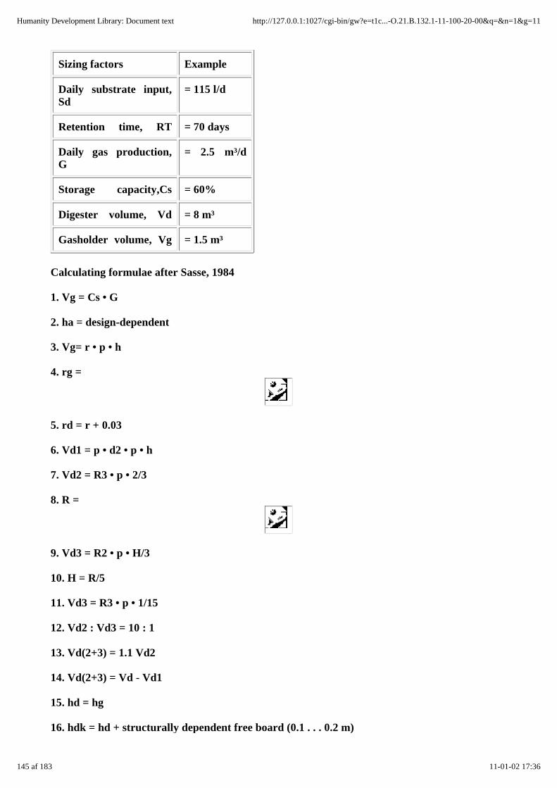
Sizing factors Example
Daily substrate input,Sd
= 115 l/d
Retention time, RT = 70 days
Daily gas production,G
= 2.5 m³/d
Storage capacity,Cs = 60%
Digester volume, Vd = 8 m³
Gasholder volume, Vg = 1.5 m³
Calculating formulae after Sasse, 1984
1. Vg = Cs • G
2. ha = design-dependent
3. Vg= r • p • h
4. rg =
5. rd = r + 0.03
6. Vd1 = p • d2 • p • h
7. Vd2 = R3 • p • 2/3
8. R =
9. Vd3 = R2 • p • H/3
10. H = R/5
11. Vd3 = R3 • p • 1/15
12. Vd2 : Vd3 = 10 : 1
13. Vd(2+3) = 1.1 Vd2
14. Vd(2+3) = Vd - Vd1
15. hd = hg
16. hdk = hd + structurally dependent free board (0.1 . . . 0.2 m)
145 af 183 11-01-02 17:36
Humanity Development Library: Document text http://127.0.0.1:1027/cgi-bin/gw?e=t1c...-O.21.B.132.1-11-100-20-00&q=&n=1&g=11

Fig. 10.1: Conceptual drawing of a floating-drum biogas plant
Vd = Vdl +Vd2 +Vd3
= digester volume
Vg = gasholder volume
Index g = gas holder
Index d = digester
Sample calculation Results
1. Vg = 0.6 • 2.5 = 1.5 m³
hg = (specified) = 0.7 m
4. r = = 0.82 m
5. r = 0.85 (chosen)
6. Vdl = 0.852 •3.14 • 0.7 = 1.58 m³
14. Vd (2+3) = 8.45 - 1.58 = 6.87 m³
8+ 14. R = = 1.45 m
146 af 183 11-01-02 17:36
Humanity Development Library: Document text http://127.0.0.1:1027/cgi-bin/gw?e=t1c...-O.21.B.132.1-11-100-20-00&q=&n=1&g=11

Fig. 10.2: Constructional drawing of a floating-drum plant. Vd = 6.4 m³, Vg = 1.8 m³. Materialrequirements: Excavation 16.0 m³, Foundation 1.6 m³, Masonry 1.1 m³, Rendered area 18.0 m²,Sheet steel 5.7 m². (Source: OEKOTOP, Sasse)
147 af 183 11-01-02 17:36
Humanity Development Library: Document text http://127.0.0.1:1027/cgi-bin/gw?e=t1c...-O.21.B.132.1-11-100-20-00&q=&n=1&g=11
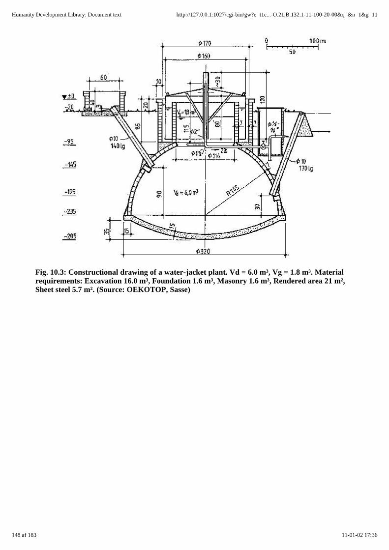
Fig. 10.3: Constructional drawing of a water-jacket plant. Vd = 6.0 m³, Vg = 1.8 m³. Materialrequirements: Excavation 16.0 m³, Foundation 1.6 m³, Masonry 1.6 m³, Rendered area 21 m²,Sheet steel 5.7 m². (Source: OEKOTOP, Sasse)
148 af 183 11-01-02 17:36
Humanity Development Library: Document text http://127.0.0.1:1027/cgi-bin/gw?e=t1c...-O.21.B.132.1-11-100-20-00&q=&n=1&g=11

Fig. 10.4: Constructional drawing of a cylindrical floating-drum plant for quarrystonemasonry. Vd = 9.4 m³, Vg = 2.5 m³. Material requirements: Excavation 21.0 m³, Foundation 1.0m³, Masonry 5.4 m³, Rendered area 27.3 m², Sheet steel 6.4 m². (Source: OEKOTOP, KVIC)
10.1.2 Fixed dome plants
Design calculation
149 af 183 11-01-02 17:36
Humanity Development Library: Document text http://127.0.0.1:1027/cgi-bin/gw?e=t1c...-O.21.B.132.1-11-100-20-00&q=&n=1&g=11

Sizing factors Example Sample calculation
Daily substrate input, Sd = 115 l/d R = (0.76 • 8)1/3= 1.85 m
Retention time,RT = 70 days r = 0.52 R= 0.96 m
Daily gas production, G = 2.5 m³/d h = 0.40 R= 0.72 m
Storage capacity, Cs = 60% p = 0.62 R= 1.14 m
Digester volume, Vd = 8 m³
Gasholder volume,Vg=G•Cs
= 1.5 m³
Vd : Vg = 5.3 : 1
Tab. 10.1: Calculating parameters for fixed-dome biogas plant (Source: Sasse1984.OEKOTOP)
Vg : Vd 1:5 1:6 1:8
R (0.76 • Vd)1/3 (0.74 • Vd)1/3 (0.72 • Vd)1/3
r 0.52 R 0.49 R 0.45 R
h 0.40 R 0.37 R 0.32 R
p 0.62 R 0.59 R 0.50 R
Fig. 10.5: Conceptual drawing of fixed-dome biogas plant. Vg gasholder volume, Vd digestervolume. (Source: OEKOTOP, Sasse)
150 af 183 11-01-02 17:36
Humanity Development Library: Document text http://127.0.0.1:1027/cgi-bin/gw?e=t1c...-O.21.B.132.1-11-100-20-00&q=&n=1&g=11
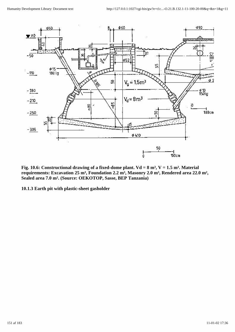
Fig. 10.6: Constructional drawing of a fixed-dome plant. Vd = 8 m³, V = 1.5 m³. Materialrequirements: Excavation 25 m³, Foundation 2.2 m³, Masonry 2.0 m³, Rendered area 22.0 m²,Sealed area 7.0 m². (Source: OEKOTOP, Sasse, BEP Tanzania)
10.1.3 Earth pit with plastic-sheet gasholder
151 af 183 11-01-02 17:36
Humanity Development Library: Document text http://127.0.0.1:1027/cgi-bin/gw?e=t1c...-O.21.B.132.1-11-100-20-00&q=&n=1&g=11
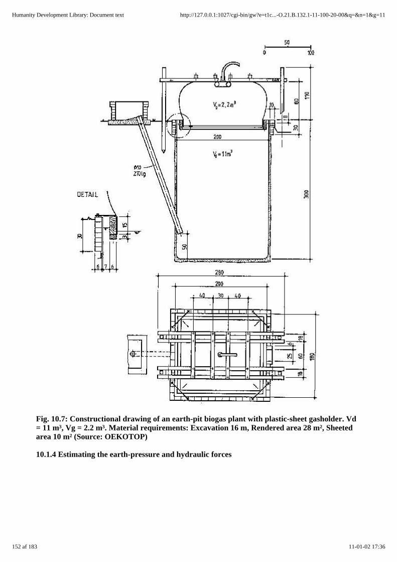
Fig. 10.7: Constructional drawing of an earth-pit biogas plant with plastic-sheet gasholder. Vd= 11 m³, Vg = 2.2 m³. Material requirements: Excavation 16 m, Rendered area 28 m², Sheetedarea 10 m² (Source: OEKOTOP)
10.1.4 Estimating the earth-pressure and hydraulic forces
152 af 183 11-01-02 17:36
Humanity Development Library: Document text http://127.0.0.1:1027/cgi-bin/gw?e=t1c...-O.21.B.132.1-11-100-20-00&q=&n=1&g=11

Fig. 10.8: Schematic diagram of earth-pressure and water-pressure forces
In-depth forces, h (e, w)
pW = wW • hw
pW = hydrostatic pressure at depth hw (m) wW = specific weight of water
= 1000 kp/m³ pW = 1000 • h (kp/m²)
pE = wE • ce • he
pE = active earth pressure, i.e. force of pressure of dry, previously loose but now compactcolumn of earth on a solid vertical wall
wE = specific weight of dry backfill earth
= 1800 . . . 2 100 kp/m³
he = height of earth column (m)
ce = coefficient of earth pressure for the earth column in question
= 0.3 . . . 0.4 (-)
pE = (600 . . . 700) • h (kp/m² )
Force acting on a surface
P(E, W) = p • A (kp = (kp/m²) • m²)
Note: The above formulae are simplified and intended only for purposes of rough estimation.
10.2 Gas-law calculations
10.2.1 Calculating the pressure drop in a gas pipe
10.2.2 Calculating gas parameters
10.2.1 Calculating the pressure drop in a gas pipe
dp = FL + Ztot
dp = pressure drop (N/m²)
153 af 183 11-01-02 17:36
Humanity Development Library: Document text http://127.0.0.1:1027/cgi-bin/gw?e=t1c...-O.21.B.132.1-11-100-20-00&q=&n=1&g=11
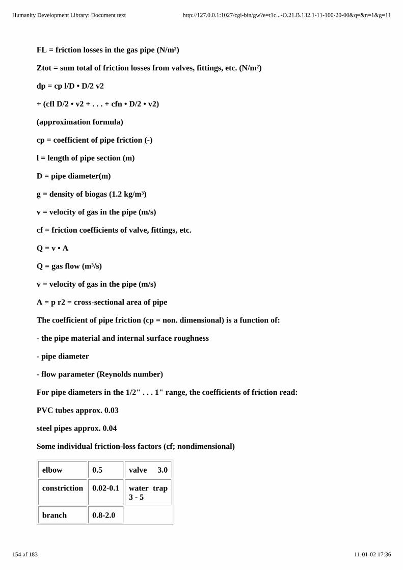
FL = friction losses in the gas pipe (N/m²)
Ztot = sum total of friction losses from valves, fittings, etc. (N/m²)
dp = cp l/D • D/2 v2
+ (cfl D/2 • v2 + . . . + cfn • D/2 • v2)
(approximation formula)
cp = coefficient of pipe friction (-)
l = length of pipe section (m)
D = pipe diameter(m)
g = density of biogas (1.2 kg/m³)
v = velocity of gas in the pipe (m/s)
cf = friction coefficients of valve, fittings, etc.
Q = v • A
Q = gas flow (m³/s)
v = velocity of gas in the pipe (m/s)
A = p r2 = cross-sectional area of pipe
The coefficient of pipe friction (cp = non. dimensional) is a function of:
- the pipe material and internal surface roughness
- pipe diameter
- flow parameter (Reynolds number)
For pipe diameters in the 1/2" . . . 1" range, the coefficients of friction read:
PVC tubes approx. 0.03
steel pipes approx. 0.04
Some individual friction-loss factors (cf; nondimensional)
elbow 0.5 valve 3.0
constriction 0.02-0.1 water trap3 - 5
branch 0.8-2.0
154 af 183 11-01-02 17:36
Humanity Development Library: Document text http://127.0.0.1:1027/cgi-bin/gw?e=t1c...-O.21.B.132.1-11-100-20-00&q=&n=1&g=11

10.2.2 Calculating gas parameters
Temperature-dependent change of volume and density
D = DN • P • TN / (PN • T)
V = VN • PN • T / (P • TN)
where:
D = density of biogas (g/l)
DN = density under s.t.p. conditions (0 °C, 1013 mbar)
V = volume of biogas (m³)
VN = volume of biogas under s.t.p. conditions
P = absolute pressure of biogas (mbar)
PN = pressure under s.t.p. conditions (1013 mbar)
T = absolute temperature of biogas (measured in ºKelvin = ºC + 273)
TN= temperature under s.t.p. conditions (0 0ºC = 273 °K)
Table 10.2: Atmospheric pressure as a function of elevation (Source: Recknagel/Sprenger,1982)
Elevation (km) 0 0.5 1.0 2 3 4 6 8
Atm.pressure(mbar)
1013 955 899 795 701 616 472 365
155 af 183 11-01-02 17:36
Humanity Development Library: Document text http://127.0.0.1:1027/cgi-bin/gw?e=t1c...-O.21.B.132.1-11-100-20-00&q=&n=1&g=11

Fig. 10.9: Nomogram for correcting gas pressures/temperatures (Source: OEKOTOP)
Determining the calorific value
156 af 183 11-01-02 17:36
Humanity Development Library: Document text http://127.0.0.1:1027/cgi-bin/gw?e=t1c...-O.21.B.132.1-11-100-20-00&q=&n=1&g=11

Fig. 10.10: Nomogram for finding the net calorific value of biogas as a function of temperature,pressure and moisture content. T gas temperature (°C), F relative dampness of biogas (%), Hu,N net calorific value (n.c.v.) of biogas under s.t.p. conditions (0 °C, 1013 mbar), Hu, T netcalorific value (n.c.v.) at gas temperature, P gas pressure (mbar), Hu, T, P net calorific value(n.c.v.) at gas temperature and pressure, PW partial pressure of water vapor, Hu, T, PF netcalorific value (n.c.v.) of biogas at gas temperature, corrected to reflect the water-vaporfraction (Source: OEKOTOP)
Using the nomogram
1. Quadrant I: Determine the net calorific value under standard conditions as a function of theCH4-fraction of the biogas
2. Quadrant II: Determine the net calorific value for a given gas temperature
3. Quadrant III: Determine the net calorific value as a function of absolute gas pressure (P)
4. Quadrant IV: Interim calculation for determining the partial water-vapor pressure as afunction of gas temperature and relative dampness. This yields the gas pressure (PF) = absolutepressure (P) - partial pressure of water vapor (PW); PF = P - PW. The expanded calorific valuedetermination with account for the moisture content occurs via quadrant III.
157 af 183 11-01-02 17:36
Humanity Development Library: Document text http://127.0.0.1:1027/cgi-bin/gw?e=t1c...-O.21.B.132.1-11-100-20-00&q=&n=1&g=11
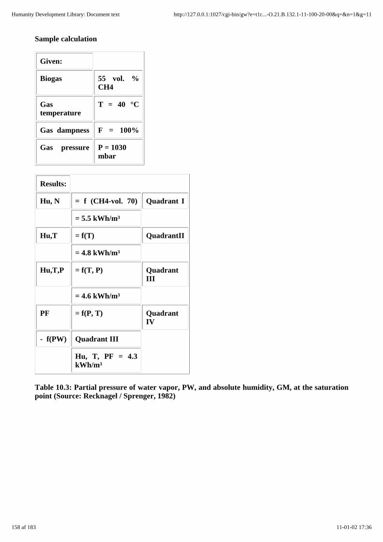
Sample calculation
Given:
Biogas 55 vol. %CH4
Gastemperature
T = 40 °C
Gas dampness F = 100%
Gas pressure P = 1030mbar
Results:
Hu, N = f (CH4-vol. 70) Quadrant I
= 5.5 kWh/m³
Hu,T = f(T) QuadrantII
= 4.8 kWh/m³
Hu,T,P = f(T, P) QuadrantIII
= 4.6 kWh/m³
PF = f(P, T) QuadrantIV
- f(PW) Quadrant III
Hu, T, PF = 4.3kWh/m³
Table 10.3: Partial pressure of water vapor, PW, and absolute humidity, GM, at the saturationpoint (Source: Recknagel / Sprenger, 1982)
158 af 183 11-01-02 17:36
Humanity Development Library: Document text http://127.0.0.1:1027/cgi-bin/gw?e=t1c...-O.21.B.132.1-11-100-20-00&q=&n=1&g=11

T(°C)
PW(mbar)
GM(g/m³)
.0 6.1 4.9
10 12.3 9.4
20 23.4 17.3
30 42.4 30.4
40 73.7 51.2
50 123.3 83.0
60 199.2 130.2
70 311.6 198.2
80 473.6 293.3
90 701.1 423.5
100 1013.3 597.7
10.3 Conversion tables
Table 10.4: SI units of calculation (selection) (Source: OEKOTOP, compiled from various sources)
159 af 183 11-01-02 17:36
Humanity Development Library: Document text http://127.0.0.1:1027/cgi-bin/gw?e=t1c...-O.21.B.132.1-11-100-20-00&q=&n=1&g=11

Quantity Symbol Unit Conversion
Length 1 m 1 m = 10 dm = 100 cm = 1000 mm
Area A m³ 1 m³ = 100 dm³ = 10000 cm³
Volume V m³ 1 m³ = 1000 dm³ = 1 mill. cm³
Mass M t; kg 1 t = 1000 kg
Density D t/m³ 1 t/m³ = 1 kg/dm³
Force, load F kN 1 kN= 1000 N ~100 kp
Stress d MN/m² 1 MN/m² = 1 N/mm² ~10 kp/cm²
Pressure p MN/m² 1 MN/m² = 1 MPa ~10 kp/cm²
Energy E kWh 1 kWh = 3.6 • 106 Ws ~3.6 • 105 kpm
Work W kNm 1 J = 1 Ws = 1 Nm 1 kNm ~ 100 kpm
Quantity of heat Q kWh 1 kWh = 3.6 X 10⁶ Ws; 1 kcal = 4187Ws
Power P kW 1 kW ~100 kpm/s = 1.36 PS
Temperature t °C, K 0ºK = -273 °C; 0ºC = 273 °K
Velocity v m/s 1 m/s= 3.6 km/in
Acceleration b m/s 1 m/s², acceleration due to gravity: 9.81m/s²
Table 10.5: Conversion of imperial measures (Source: Sasse, 1984)
160 af 183 11-01-02 17:36
Humanity Development Library: Document text http://127.0.0.1:1027/cgi-bin/gw?e=t1c...-O.21.B.132.1-11-100-20-00&q=&n=1&g=11
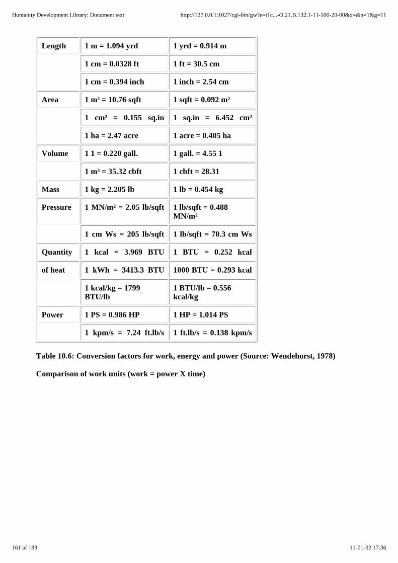
Length 1 m = 1.094 yrd 1 yrd = 0.914 m
1 cm = 0.0328 ft 1 ft = 30.5 cm
1 cm = 0.394 inch 1 inch = 2.54 cm
Area 1 m² = 10.76 sqft 1 sqft = 0.092 m²
1 cm² = 0.155 sq.in 1 sq.in = 6.452 cm²
1 ha = 2.47 acre 1 acre = 0.405 ha
Volume 1 1 = 0.220 gall. 1 gall. = 4.55 1
1 m³ = 35.32 cbft 1 cbft = 28.31
Mass 1 kg = 2.205 lb 1 lb = 0.454 kg
Pressure 1 MN/m² = 2.05 lb/sqft 1 lb/sqft = 0.488MN/m²
1 cm Ws = 205 lb/sqft 1 lb/sqft = 70.3 cm Ws
Quantity 1 kcal = 3.969 BTU 1 BTU = 0.252 kcal
of heat 1 kWh = 3413.3 BTU 1000 BTU = 0.293 kcal
1 kcal/kg = 1799BTU/lb
1 BTU/lb = 0.556kcal/kg
Power 1 PS = 0.986 HP 1 HP = 1.014 PS
1 kpm/s = 7.24 ft.lb/s 1 ft.lb/s = 0.138 kpm/s
Table 10.6: Conversion factors for work, energy and power (Source: Wendehorst, 1978)
Comparison of work units (work = power X time)
161 af 183 11-01-02 17:36
Humanity Development Library: Document text http://127.0.0.1:1027/cgi-bin/gw?e=t1c...-O.21.B.132.1-11-100-20-00&q=&n=1&g=11
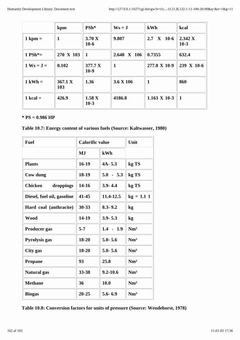
kpm PSh* Ws = J kWh kcal
1 kpm = 1 3.70 X10⁻⁶
9.807 2.7 X 10⁻⁶ 2.342 X10⁻³
1 PSh*= 270 X 103 1 2.648 X 10⁶ 0.7355 632.4
1 Ws = J = 0.102 377.7 X10⁻⁹
1 277.8 X 10⁻⁹ 239 X 10-6
1 kWh = 367.1 X10³
1.36 3.6 X 10⁶ 1 860
1 kcal = 426.9 1.58 X10⁻³
4186.8 1.163 X 10⁻³ 1
* PS = 0.986 HP
Table 10.7: Energy content of various fuels (Source: Kaltwasser, 1980)
Fuel Calorific value Unit
MJ kWh
Plants 16-19 4A- 5.3 kg TS
Cow dung 18-19 5.0 - 5.3 kg TS
Chicken droppings 14-16 3.9- 4.4 kg TS
Diesel, fuel oil, gasoline 41-45 11.4-12.5 kg = 1.1 1
Hard coal (anthracite) 30-33 8.3- 9.2 kg
Wood 14-19 3.9- 5.3 kg
Producer gas 5-7 1.4 - 1.9 Nm³
Pyrolysis gas 18-20 5.0- 5.6 Nm³
City gas 18-20 5.0- 5.6 Nm³
Propane 93 25.8 Nm³
Natural gas 33-38 9.2-10.6 Nm³
Methane 36 10.0 Nm³
Biogas 20-25 5.6- 6.9 Nm³
Table 10.8: Conversion factors for units of pressure (Source: Wendehorst, 1978)
162 af 183 11-01-02 17:36
Humanity Development Library: Document text http://127.0.0.1:1027/cgi-bin/gw?e=t1c...-O.21.B.132.1-11-100-20-00&q=&n=1&g=11
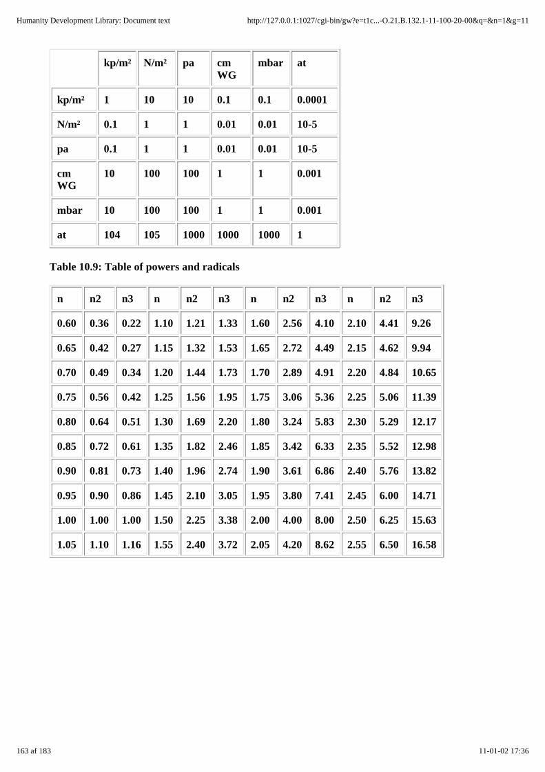
kp/m² N/m² pa cmWG
mbar at
kp/m² 1 10 10 0.1 0.1 0.0001
N/m² 0.1 1 1 0.01 0.01 10-5
pa 0.1 1 1 0.01 0.01 10-5
cmWG
10 100 100 1 1 0.001
mbar 10 100 100 1 1 0.001
at 104 105 1000 1000 1000 1
Table 10.9: Table of powers and radicals
n n2 n3 n n2 n3 n n2 n3 n n2 n3
0.60 0.36 0.22 1.10 1.21 1.33 1.60 2.56 4.10 2.10 4.41 9.26
0.65 0.42 0.27 1.15 1.32 1.53 1.65 2.72 4.49 2.15 4.62 9.94
0.70 0.49 0.34 1.20 1.44 1.73 1.70 2.89 4.91 2.20 4.84 10.65
0.75 0.56 0.42 1.25 1.56 1.95 1.75 3.06 5.36 2.25 5.06 11.39
0.80 0.64 0.51 1.30 1.69 2.20 1.80 3.24 5.83 2.30 5.29 12.17
0.85 0.72 0.61 1.35 1.82 2.46 1.85 3.42 6.33 2.35 5.52 12.98
0.90 0.81 0.73 1.40 1.96 2.74 1.90 3.61 6.86 2.40 5.76 13.82
0.95 0.90 0.86 1.45 2.10 3.05 1.95 3.80 7.41 2.45 6.00 14.71
1.00 1.00 1.00 1.50 2.25 3.38 2.00 4.00 8.00 2.50 6.25 15.63
1.05 1.10 1.16 1.55 2.40 3.72 2.05 4.20 8.62 2.55 6.50 16.58
163 af 183 11-01-02 17:36
Humanity Development Library: Document text http://127.0.0.1:1027/cgi-bin/gw?e=t1c...-O.21.B.132.1-11-100-20-00&q=&n=1&g=11

n n1/3 n n1/3 n n1/3 n n1/3 n n1/3 n n1/3
0.001 0.10 0.22 0.60 1.33 1.10 4.10 1.60 9.26 2.10 17.58 2.60
0.003 0.15 0.27 0.65 1.53 1.15 4.49 1.65 9.94 2.15 18.61 2.65
0.008 0.20 0.34 0.70 1.73 1.20 4.91 1.70 10.65 2.20 19.68 2.70
0.016 0.25 0.42 0.75 1.95 1.25 5.36 1.75 11.39 2.25 20.80 2.75
0.027 0.30 0.51 0.80 2.20 1.30 5.83 1.80 12.17 2.30 21.95 2.80
0.043 0.35 0.61 0.85 2.46 1.35 6.33 1.85 12.98 2.35 23.15 2.85
0.064 0.40 0.73 0.90 2.74 1.40 6.86 1.90 13.82 2.40 24.39 2.90
0.091 0.45 0.86 0.95 3.05 1.45 7.41 1.95 14.71 2.45 25.67 2.95
0.125 0.50 1.00 1.00 3.38 1.50 8.00 2.00 15.63 2.50 27.0 3.00
0.166 0.55 1.16 1.05 3.72 1.55 8.62 2.05 16.58 2.55 28.37 3.05
164 af 183 11-01-02 17:36
Humanity Development Library: Document text http://127.0.0.1:1027/cgi-bin/gw?e=t1c...-O.21.B.132.1-11-100-20-00&q=&n=1&g=11

Fig. 10.11: Fundamental geometric formulae (Source: Sasse 1984)
10.4 Charts and tables for use in performing micro-economic
Notes on using the data sheet (table 10.10)
The data survey (data sheet, table 10.10) contains fictive, but nonetheless substantially realistic,data on a family-size biogas plant. Those data are reffered to for explaining and calculating thearithmetic models described in chapter 8. Such data must be ascertained separately for eachproject site.
Notes on the individual data-sheet items
1. In order to keep the calculations uncomplicated, an unrealistically constant annual rate ofinflation is assumed. It is possible to account for different inflation rates in the variousanalytical procedures. For explanatory details beyond those offered in this guide, please referto Finck/Oelert, chapter C III.
2. Calculatory interest rate, i: assumed rate of interest for evaluating the cash flows (incomeand expenditure) generated by a biogas plant during its technical service plant. Proceeding onthe assumption that the expenditures are all the more burdensome, the earlier they fall due,while income is all the more valuable, the earlier it is earned, all cash flows occuring inconnection with the investment are compounded/discounted at an assumed rate for a fixedpoint in time. Please refer to chapter 8.4 for the calculation procedure.
3. Investment costs (incl. wages):
- planning
- land aquisition/leasing (as applicable)
- civil works
- building and structures/digester
165 af 183 11-01-02 17:36
Humanity Development Library: Document text http://127.0.0.1:1027/cgi-bin/gw?e=t1c...-O.21.B.132.1-11-100-20-00&q=&n=1&g=11
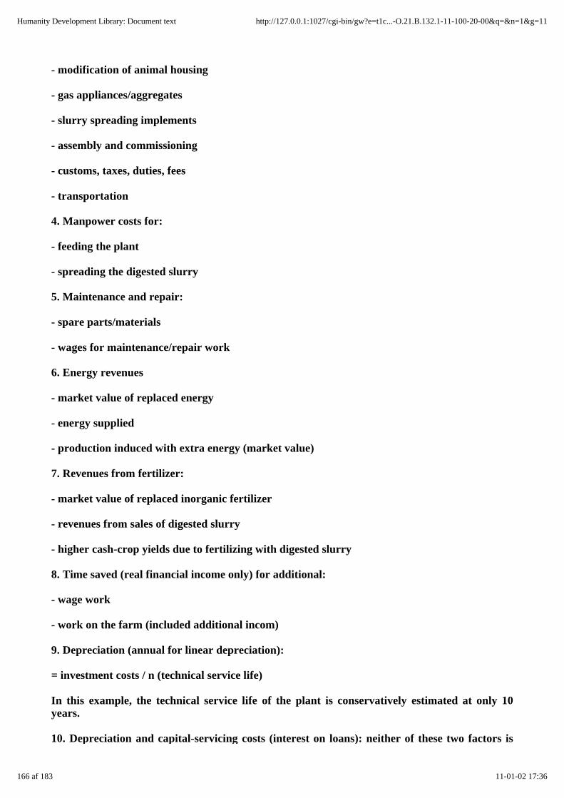
- modification of animal housing
- gas appliances/aggregates
- slurry spreading implements
- assembly and commissioning
- customs, taxes, duties, fees
- transportation
4. Manpower costs for:
- feeding the plant
- spreading the digested slurry
5. Maintenance and repair:
- spare parts/materials
- wages for maintenance/repair work
6. Energy revenues
- market value of replaced energy
- energy supplied
- production induced with extra energy (market value)
7. Revenues from fertilizer:
- market value of replaced inorganic fertilizer
- revenues from sales of digested slurry
- higher cash-crop yields due to fertilizing with digested slurry
8. Time saved (real financial income only) for additional:
- wage work
- work on the farm (included additional incom)
9. Depreciation (annual for linear depreciation):
= investment costs / n (technical service life)
In this example, the technical service life of the plant is conservatively estimated at only 10years.
10. Depreciation and capital-servicing costs (interest on loans): neither of these two factors is
166 af 183 11-01-02 17:36
Humanity Development Library: Document text http://127.0.0.1:1027/cgi-bin/gw?e=t1c...-O.21.B.132.1-11-100-20-00&q=&n=1&g=11

included as a cost factor in the dynamic models presented in chapter 8, because the cost ofinvestment is equal to the sum of cash values from depreciation and interest (cf. Brandt, 1982,for details). In this example, it is assumed that no external capital is needed, i.e. that the biogasplant is fully financed with internal capital.
Table 10.10: Data sheet for economic analysis (Source OEKOTOP; Finck/Oelert, Table 1)
Project title: Location: Owner: Type of plant/digester volume:
Technical service life: years
Item Period 0 1 2 3 4 5 6 7
Year 19... 19... 19... 19... 19... 19... 19... 19...
1.1 General inflation rate 1) % 34 34 34 34 34 34 34 34
1.2 Market interest rate, p % 48 48 48 48 48 48 48 48
1.3 Assumed interest rate, i2)
% 10.4 10.4 10.4 10.4 10.4 10.4 10.4 10.4
2. Investment costs, I 3) CU 1100
3.1 Manpower costs 4) CU - - - - - - - -
3.2 Maintenance and repair5)
CU - 30 30 30 30 30 30 30
spare-parts requirement
4.1 Taxes and levies notlinked to profit
CU - - - - - - - -
4.2 Other expenditures CU - 50 50 50 50 50 50 50
5. Total operating costs, Co 35 35 35 35 35 35 35
6.1 Energy-related revenues6)
CU - 210 210 210 210 210 210 210
6.2 Revenues from fertilizer7)
CU - 250 250 250 250 250 250 250
6.3 Time saved 8) CU - - - - - - - -
6.4 Other income CU - - - - - - - -
6.5 Subsidies CU - - - - - - - -
7. Total income CU - 235 235 235 235 235 235 235
8. Returns (item 7- item 5) CU 200 200 200 200 200 200 200 200
9. Depreciation 9) CU 110 110 110 110 110 110 110 110
167 af 183 11-01-02 17:36
Humanity Development Library: Document text http://127.0.0.1:1027/cgi-bin/gw?e=t1c...-O.21.B.132.1-11-100-20-00&q=&n=1&g=11
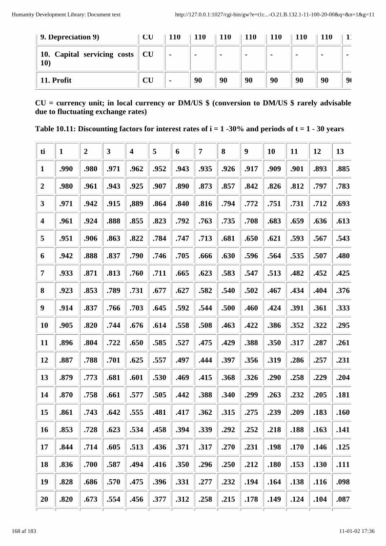
9. Depreciation 9) CU 110 110 110 110 110 110 110 110
10. Capital servicing costs10)
CU - - - - - - - -
11. Profit CU - 90 90 90 90 90 90 90
CU = currency unit; in local currency or DM/US $ (conversion to DM/US $ rarely advisabledue to fluctuating exchange rates)
Table 10.11: Discounting factors for interest rates of i = 1 -30% and periods of t = 1 - 30 years
ti 1 2 3 4 5 6 7 8 9 10 11 12 13
1 .990 .980 .971 .962 .952 .943 .935 .926 .917 .909 .901 .893 .885
2 .980 .961 .943 .925 .907 .890 .873 .857 .842 .826 .812 .797 .783
3 .971 .942 .915 ,889 .864 .840 .816 .794 .772 .751 .731 .712 .693
4 .961 .924 .888 .855 .823 .792 .763 .735 .708 .683 .659 .636 .613
5 .951 .906 .863 .822 .784 .747 .713 .681 .650 .621 .593 .567 .543
6 .942 .888 .837 .790 .746 .705 .666 .630 .596 .564 .535 .507 .480
7 .933 .871 .813 .760 .711 .665 .623 .583 .547 .513 .482 .452 .425
8 .923 .853 .789 .731 .677 .627 .582 .540 .502 .467 .434 .404 .376
9 .914 .837 .766 .703 .645 .592 .544 .500 .460 .424 .391 .361 .333
10 .905 .820 .744 .676 .614 .558 .508 .463 .422 .386 .352 .322 .295
11 .896 .804 .722 .650 .585 .527 .475 .429 .388 .350 .317 .287 .261
12 .887 .788 .701 .625 .557 .497 .444 .397 .356 .319 .286 .257 .231
13 .879 .773 .681 .601 .530 .469 .415 .368 .326 .290 .258 .229 .204
14 .870 .758 .661 .577 .505 .442 .388 .340 .299 .263 .232 .205 .181
15 .861 .743 .642 .555 .481 .417 .362 .315 .275 .239 .209 .183 .160
16 .853 .728 .623 .534 .458 .394 .339 .292 .252 .218 .188 .163 .141
17 .844 .714 .605 .513 .436 .371 .317 .270 .231 .198 .170 .146 .125
18 .836 .700 .587 .494 .416 .350 .296 .250 .212 .180 .153 .130 .111
19 .828 .686 .570 .475 .396 .331 .277 .232 .194 .164 .138 .116 .098
20 .820 .673 .554 .456 .377 .312 .258 .215 .178 .149 .124 .104 .087
168 af 183 11-01-02 17:36
Humanity Development Library: Document text http://127.0.0.1:1027/cgi-bin/gw?e=t1c...-O.21.B.132.1-11-100-20-00&q=&n=1&g=11
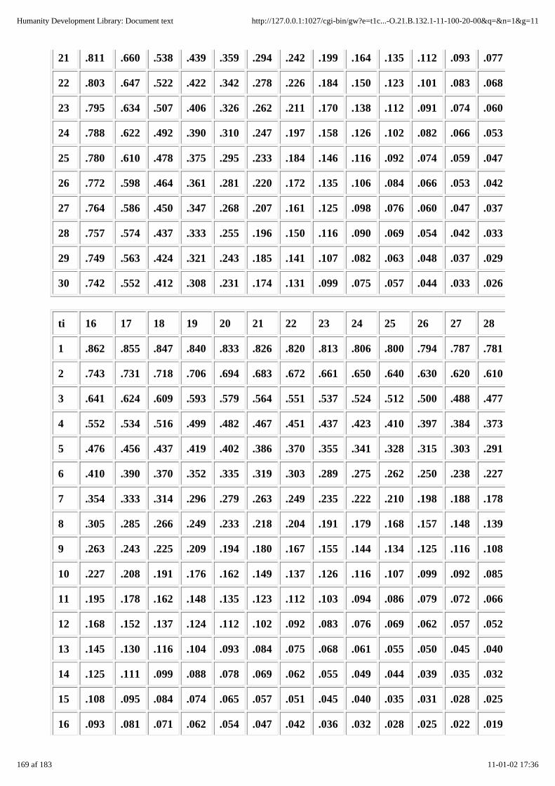
21 .811 .660 .538 .439 .359 .294 .242 .199 .164 .135 .112 .093 .077
22 .803 .647 .522 .422 .342 .278 .226 .184 .150 .123 .101 .083 .068
23 .795 .634 .507 .406 .326 .262 .211 .170 .138 .112 .091 .074 .060
24 .788 .622 .492 .390 .310 .247 .197 .158 .126 .102 .082 .066 .053
25 .780 .610 .478 .375 .295 .233 .184 .146 .116 .092 .074 .059 .047
26 .772 .598 .464 .361 .281 .220 .172 .135 .106 .084 .066 .053 .042
27 .764 .586 .450 .347 .268 .207 .161 .125 .098 .076 .060 .047 .037
28 .757 .574 .437 .333 .255 .196 .150 .116 .090 .069 .054 .042 .033
29 .749 .563 .424 .321 .243 .185 .141 .107 .082 .063 .048 .037 .029
30 .742 .552 .412 .308 .231 .174 .131 .099 .075 .057 .044 .033 .026
ti 16 17 18 19 20 21 22 23 24 25 26 27 28
1 .862 .855 .847 .840 .833 .826 .820 .813 .806 .800 .794 .787 .781
2 .743 .731 .718 .706 .694 .683 .672 .661 .650 .640 .630 .620 .610
3 .641 .624 .609 .593 .579 .564 .551 .537 .524 .512 .500 .488 .477
4 .552 .534 .516 .499 .482 .467 .451 .437 .423 .410 .397 .384 .373
5 .476 .456 .437 .419 .402 .386 .370 .355 .341 .328 .315 .303 .291
6 .410 .390 .370 .352 .335 .319 .303 .289 .275 .262 .250 .238 .227
7 .354 .333 .314 .296 .279 .263 .249 .235 .222 .210 .198 .188 .178
8 .305 .285 .266 .249 .233 .218 .204 .191 .179 .168 .157 .148 .139
9 .263 .243 .225 .209 .194 .180 .167 .155 .144 .134 .125 .116 .108
10 .227 .208 .191 .176 .162 .149 .137 .126 .116 .107 .099 .092 .085
11 .195 .178 .162 .148 .135 .123 .112 .103 .094 .086 .079 .072 .066
12 .168 .152 .137 .124 .112 .102 .092 .083 .076 .069 .062 .057 .052
13 .145 .130 .116 .104 .093 .084 .075 .068 .061 .055 .050 .045 .040
14 .125 .111 .099 .088 .078 .069 .062 .055 .049 .044 .039 .035 .032
15 .108 .095 .084 .074 .065 .057 .051 .045 .040 .035 .031 .028 .025
16 .093 .081 .071 .062 .054 .047 .042 .036 .032 .028 .025 .022 .019
169 af 183 11-01-02 17:36
Humanity Development Library: Document text http://127.0.0.1:1027/cgi-bin/gw?e=t1c...-O.21.B.132.1-11-100-20-00&q=&n=1&g=11
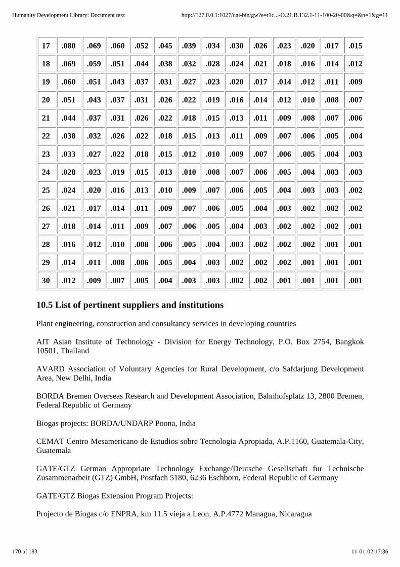
17 .080 .069 .060 .052 .045 .039 .034 .030 .026 .023 .020 .017 .015
18 .069 .059 .051 .044 .038 .032 .028 .024 .021 .018 .016 .014 .012
19 .060 .051 .043 .037 .031 .027 .023 .020 .017 .014 .012 .011 .009
20 .051 .043 .037 .031 .026 .022 .019 .016 .014 .012 .010 .008 .007
21 .044 .037 .031 .026 .022 .018 .015 .013 .011 .009 .008 .007 .006
22 .038 .032 .026 .022 .018 .015 .013 .011 .009 .007 .006 .005 .004
23 .033 .027 .022 .018 .015 .012 .010 .009 .007 .006 .005 .004 .003
24 .028 .023 .019 .015 .013 .010 .008 .007 .006 .005 .004 .003 .003
25 .024 .020 .016 .013 .010 .009 .007 .006 .005 .004 .003 .003 .002
26 .021 .017 .014 .011 .009 .007 .006 .005 .004 .003 .002 .002 .002
27 .018 .014 .011 .009 .007 .006 .005 .004 .003 .002 .002 .002 .001
28 .016 .012 .010 .008 .006 .005 .004 .003 .002 .002 .002 .001 .001
29 .014 .011 .008 .006 .005 .004 .003 .002 .002 .002 .001 .001 .001
30 .012 .009 .007 .005 .004 .003 .003 .002 .002 .001 .001 .001 .001
10.5 List of pertinent suppliers and institutions
Plant engineering, construction and consultancy services in developing countries
AIT Asian Institute of Technology - Division for Energy Technology, P.O. Box 2754, Bangkok10501, Thailand
AVARD Association of Voluntary Agencies for Rural Development, c/o Safdarjung DevelopmentArea, New Delhi, India
BORDA Bremen Overseas Research and Development Association, Bahnhofsplatz 13, 2800 Bremen,Federal Republic of Germany
Biogas projects: BORDA/UNDARP Poona, India
CEMAT Centro Mesamericano de Estudios sobre Tecnologia Apropiada, A.P.1160, Guatemala-City,Guatemala
GATE/GTZ German Appropriate Technology Exchange/Deutsche Gesellschaft fur TechnischeZusammenarbeit (GTZ) GmbH, Postfach 5180, 6236 Eschborn, Federal Republic of Germany
GATE/GTZ Biogas Extension Program Projects:
Projecto de Biogas c/o ENPRA, km 11.5 vieja a Leon, A.P.4772 Managua, Nicaragua
170 af 183 11-01-02 17:36
Humanity Development Library: Document text http://127.0.0.1:1027/cgi-bin/gw?e=t1c...-O.21.B.132.1-11-100-20-00&q=&n=1&g=11

Biogas Extension Service c/o CAMARTEC, P.O. Box 764, Arusha, Tanzania Projet Biogaz Cankuzo,D/S 148, Bujumbura, Burundi
CDB/GATE Biogas Team c/o CDB, P.O. Box 407, Wildey St. Michael, Barbados
Proyeto Biogas PAAC-UMMS-GATE, Casilla 4740, Cochabamba Bolivia
Special Energy Program biogas projects (GTZ-Div.34) GTZ Special Energy Program, P.O. Box41607, Nairobi, Kenya Projet Special de l'Energie, c/o I.V.E., B.P. 5321 Ouagadougou, Burkina Faso
KVIC Khadi and Village Industries Commission, Gobar Gas Scheme, Ivla Rees, Vila Parle, Bombay400 056, India
Maya Farms Angona, Rizal, Philippines
OEKOTOP Gesellschaft fur Angepaßte Technologien in Entwicklungsgebieten, Bingerstr. 25a, 1000Berlin 33, Federal Republic of Germany
Biogas projects (by order of GTZ): Projet Biogaz c/o SODEPRA Ferkessedougou, Cote d'IvoireProyecto Biogas Colombo-Aleman c/o CVC, Apto. A2366, Cali, Colombia
RED-Latino Americana de Biogas, Emprater, W3 Norte Q515, Brazilia, Brazil
Equipment producers / suppliers
Elster AG, Postfach 129,6500 Mainz, Federal Republic of Germany
Products: gasmeters
Kromschroder AG, Postfach 2809,4500 Osnabruck, Federal Republic of Germany
Products: full range of gas valves
Metallurgica Jackwal Ltd., Rua Braz Cardoso 674, Vila Nova Canceicao, Sao Paulo, Brazil
Products: lamps, burners, reducing valves
OEKOTOP GmbH, Berlin
Product: portable biogas measuring set
Patel Gas Crafters Ltd., Shree Sai Bazar, Mahatma Gandhi Road, Bombay 400 054, India
Products: lamps, burners
Saron Vdyog, Shanghai, PR China
Products: gasmeters, lamps, burners
Service Centre for Development on New Energy, NO. 33 Fugiun Skeet, Shijiazkuang, PR
China
Products: burners, motors
171 af 183 11-01-02 17:36
Humanity Development Library: Document text http://127.0.0.1:1027/cgi-bin/gw?e=t1c...-O.21.B.132.1-11-100-20-00&q=&n=1&g=11
Shanghai Bioenergy, Shanghai, PR China
Products: gasmeters, lamps, burners, motors
T.A. Schiller, Postfach 1224, 2072 Bargteheide, Federal Republic of Germany
Products: lamps, burners, motors
Producers of biogas-fueled engines
Ford AG, Edsel-Ford-Str., 5000 Cologne 71, Federal Republic of Germany
- Type 2274 E, 15-25 kW, 1500 - 3000 min-1, 4-cylinder, water-cooled, spark ignition
Henkelhausen, Postfach 9149, 4150 Krefeld 12, Federal Republic of Germany
- Series GFL 912, 19~0 kW, 1500-2300 min-1, 3-, 4-, 5-, 6-cylinder, air-cooled, spark ignition
- Series GFL 413, 55 - 140 kW, 1500 - 2300 min-1, 5-, 6-, 8-, 10-, 12-cylinder, air-cooled, sparkignition
Kirloska, India, German representative: Schule Co., Postfach 260620, 2000 Hamburg 26,
Federal Republic of Germany
- Series AVG, TVG, CAG, TAG, 5 - 12 kW, 1200 - 2000 min-1, 1-, 2-cylinder, air-cooled orwater-cooled, dual-fuel
MWM AG, Carl-Benz-Str., 6800 Mannheim, Federal Republic of Germany
- Series G 227, 18 - 40 kW, 1500 - 2200 min-1, 3-, 4-, 6-cylinder, water-cooled, spark ignition
10.6 Selected literature
Biotechnical fundamentals and plant engineering
Anaerobic Digestion, Proceedings of the Fourth International Symposium on Aerobic Digestion, heldin Guangzkou, China on 11 -15 November 1985
Baader et al., Biogas in Theorie and Praxis. KTBL Darmstadt 1980
Biogas Technology Resource Index, Tata Energy Documentation and Information Cenke, Bombay1985
BORDA, Biogas Workshop on Community Plants - Input Papers, Bremen 1984
Braun, R, Biogas - Methangarung organischer Abfalle, Vienna/New York 1982
Guidebook on Biogas Development, Energy Resources Development Series, ESCAP, Bangkok 1980
Hohlfeld, J. et al., Production and Utilization of Biogas in Rural Areas of Industrialized andDeveloping countries, GTZ Eschborn 1986
172 af 183 11-01-02 17:36
Humanity Development Library: Document text http://127.0.0.1:1027/cgi-bin/gw?e=t1c...-O.21.B.132.1-11-100-20-00&q=&n=1&g=11

Eggeling, G. et al., Biogas Manual for the Realisation of Biogas Programmes, BORDA, Bremen 1980
Biogasanlagen in Europa, Neue Energien, Resultate der Energieforschung der EuropaischenGemeinschaft, TUV Rheinland, Cologne 1985
Sasse, L., The Biogas Plant, GTZ/GATE, Eschborn 1984
Wellinger et al., Biogas-Handbuch, Grundlagen, Planung, Betrieb landwrrtschaftlicher Anlagen,Aarau 1984
Agriculture
Comberg, G. (Ed.), Tierzuchtungslehre, Stuttga~t 1980
Demant, D., GATE/GTZ, Arbeitspapier zur einheitlichen Versuchsmethodik furFaulachlammdungeversuche Eschborn 1987
Memento de l'agronome, Republique Francaise, Ministere de la Cooperation, 1984
Rehm/Espig, Die Kulturpflanzen der Tropen und Subtropen, Stuttgart 1976
Williamson, G./Payne, W.J.A., An Introduction to Animal Husbandry in the Tropics, London/NewYork 1977
Economic aspects and dissemination/diffusion
Brandt, H., Projektplanung in der kleinbauerlichen Produktion, Berlin 1982
Finck, H./Oelert, G., A Guide to the Financial Evaluation of Investment Projects in Energy Supply,GTZ Eschborn 1982
Oelert et al., Economic Issues of Renewable Energy Systems - A Guide to Project Planning, Eschborn1985
10.7 Lists and indexes
10.7.1 Illustrations
10.7.2 Tables
10.7.3 Abbreviations
10.7.1 Illustrations
Fig. 1.1: A typical biogas-system configuration
Fig. 2.1: Biogasplanningmodules
Fig. 3.1: Global 15 °C isotherms for January and July, indicating the biogas-conducive temperaturezone
Fig. 3.2: Integration of a biogas plant into the agricultural production cycle
Fig. 3.3: Pen with concrete floor and collecting channel for dung and urine
173 af 183 11-01-02 17:36
Humanity Development Library: Document text http://127.0.0.1:1027/cgi-bin/gw?e=t1c...-O.21.B.132.1-11-100-20-00&q=&n=1&g=11

Fig. 3.4: Stanchion barn with floating gutter
Fig. 3.5: Cow-cubicle barn with floating gutter
Fig. 3.6: Piggery with group bays (no litter)
Fig. 3.7: Slurry storage and composting
Fig. 3.8: Flow diagram for integral farming with a biogas plant
Fig. 3.9: Site plan of the Bouake Ecofarm in Cote d'Ivoire
Fig. 4.1: Balancing the-energy demand with the biogas production
Fig. 5.1: Three-stage anaerobic fermentation
Fig. 5.2: Gas yield as a function of temperature and retention time (fT,RT-curves)
Fig. 5.3: The batch-feed principle vs the continuous-feed principle
Fig. 5.4: The fermentation channel vs the complete-mixed digester
Fig. 5.5: Slurry flow for various configurations of feed, discharge and stirring
Fig. 5.6: Floating-drum plant with internal guide frame
Fig. 5.7: Water-jacket plant with external guide frame
Fig. 5.8: Cylindrical plant design for quarrystone masonry construction
Fig. 5.9: Basic function of a fixed-dome biogas plant
Fig. 5.10: Fixed-dome plant with cenkal entry hatch
Fig. 5.11: Fixed-dome plant with suspended dome
Fig. 5.12: Horizontal balloon-type biogas plant
Fig. 5.13: Earth-pit plant with plastic-sheet gasholder
Fig. 5.14: Ferrocement biogas plant
Fig. 5.15: Horizontal biogas plant (KVIC shallow design)
Fig. 5.16: Mixing pit
Fig. 5.17: Mixing pit, gutter and toilet drain pipe
Fig. 5.18: Inlet and outlet for fixed-dome and floating-drum plants
Fig. 5.19: Forces acting on a spherical-dome digester
Fig. 5.20: Level line, excavation and foundation
174 af 183 11-01-02 17:36
Humanity Development Library: Document text http://127.0.0.1:1027/cgi-bin/gw?e=t1c...-O.21.B.132.1-11-100-20-00&q=&n=1&g=11

Fig. 5.21: Construction of a spherical dome from masonry
Fig. 5.22: Construction of a metal gasholder with internal guide frame
Fig. 5.23: Construction of a fixed-dome gasholder
Fig. 5.24: Entry hatch of a fixed-dome biogas plant
Fig. 5.25: Sealing the masonry with paraffin
Fig. 5.26: Separate, mobile, plastic-sheet gasholder
Fig. 5.27: Gas pipe, valves and fittings of a biogas plant
Fig. 5.28: Gas valves and fittings: U-tube pressure gauge, water trap with drain valve, U-tube waterseparator, "gravel pot" flashback arrestor
Fig. 5.29: Ferric-hydrate gas purifier
Fig. 5.30: Schematic drawing of a biogas burner and its parts
Fig. 5.31: Various types of biogas burners
Fig. 5.32: Schematic drawing of a biogas lamp
Fig. 5.33: Schematic drawing of a radiant heater
Fig. 5.34: Schematic drawing of an incubator
Fig. 5.35: Various gas mixers for spark-ignition and diesel engines
Fig. 5.36: Consumption of diesel and biogas by a 10-kW engine
Fig. 5.37: Energy shares of an internal-combustion engine
Fig. 5.38: Measuringinstruments for biogas field tests
Fig. 6.1: Basic principle of organic wastewater treatment
Fig. 6.2: Biogas plant in Ferkessedougou - system OEKOTOP
Fig. 7.1: Water-seal testing of a digester
Fig. 7.2: Seal testing (water and gas) of a fixed-dome plant
Fig. 7.3: Gas-seal testing of a metal-gasholder
Fig. 7.4: Pressure testing a gas pipe
Fig. 8.1: Basic elements of an economic analysis
Fig. 8.2: Costs and benefits of a fixed-dome biogas plant
175 af 183 11-01-02 17:36
Humanity Development Library: Document text http://127.0.0.1:1027/cgi-bin/gw?e=t1c...-O.21.B.132.1-11-100-20-00&q=&n=1&g=11
Fig. 10.1: Conceptual drawing of a floating-drum biogas plant
Fig. 10.2: Constructional drawing of a floating-drum plant
Fig. 10.3: Constructional drawing of a waterjacket plant
Fig. 10.4: Constructional drawing of a cylindrical floating-drum plant for quarrystone masonry
Fig. 10.5: Conceptual drawing of a fixed-dome biogas plant
Fig. 10.6: Constructional drawing of a fixed-dome plant
Fig. 10.7: Constructional drawing of an earth-pit biogas plant with plastic-sheet gasholder
Fig. 10.8: Schematic diagram of earth-pressure and water-pressure forces
Fig. 10.9: Nomogram for correcting gas pressures/temperatures
Fig. 10.10: Nomogram for finding the net calorific value of biogas as a function oftemperaturepressure and moisture content
Fig. 10.11: Fundamental geometric formulae
10.7.2 Tables
Tab. 2.1: Detailed planning guide for biogas plants
Tab. 3.1: Climate zones and their suitability for biogas plants
Tab. 3.2: Standard liveweight values of animal husbandry and average manure yields (dung + urine)as percentages of liveweight
Tab. 3.3: TS- and VS-contents of green plants
Tab. 3.4: Digestion characteristics of animal-husbandry residues
Tab. 3.5: Mean gas yields from various types of agricultural biomass
Tab. 3.6: C/N-ratios of various substrates
Tab. 3.7: Biogas compatibility of farm types
Tab. 3.8: Survival time of pathogens in biogas plants
Tab. 3.9: Concentration of nutrients in the digested slurry of various substrates
Tab. 3.10: Effects of digested slurry on crop yields
Tab. 4.1: Outline for determining biogas demand
Tab. 4.2: Outline for determining biomass incidence
Tab. 4.3: Simplified gas-yield values for substrate from cattle and pigs
176 af 183 11-01-02 17:36
Humanity Development Library: Document text http://127.0.0.1:1027/cgi-bin/gw?e=t1c...-O.21.B.132.1-11-100-20-00&q=&n=1&g=11

Tab. 5.1: Basic criteria for acetobacters (acid forming bacteria) and methanobacters (methaneformingbacteria)
Tab. 5.2: Energy potential of organic compounds
Tab. 5.3: Energetical comparison of aerobic and anaerobic fermentation
Tab. 5.4: Temperature ranges for anaerobic fermentation
Tab. 5.5: pH ranges for biomethanation
Tab. 5.6: Substances with an inhibiting effect on biomethanation
Tab. 5.7: Comparison of various plant designs
Tab. 5.8: Common substrate mixing ratios
Tab. 5.9: Mortar mixing ratios
Tab. 5.10: Suitability tests for rendering/mortar sands
Tab. 5.11: Quality ratings for various dome-sealing materials
Tab. 5.12: Properties of plastic sheeting - gasholder suitability ratings
Tab. 5.13: Gas-pipe pressure losses
Tab. 5.14: Composition and properties of biogas and its constituents under s.t.p. conditions (0 °C,1013 mbar)
Tab. 5.15: Pointers on flame adjustment
Tab. 5.16: Comparison of various internationally marketed biogas burners
Tab. 5.17: Biogas consumption for cooking
Tab. 5.18: Tests for biogas cookers/stoves
Tab. 5.19: Standard lighting terms and units of measure
Tab. 5.20: Comparison of various biogas lamps
Tab. 5.21: Artificial brooding requirements, exemplified for a chick incubator
Tab. 5.22: Technical data of absorption refrigerators
Tab. 5.23: Engine-conversion requirements for various duty and control modes
Tab. 6.1: Some examples of biogas production from agro-industrial residues and wastewater
Tab. 6.2: Technical data of the Ferkessedougou biogas plant
Tab. 6.3: Slaughterhouse waste quantities
177 af 183 11-01-02 17:36
Humanity Development Library: Document text http://127.0.0.1:1027/cgi-bin/gw?e=t1c...-O.21.B.132.1-11-100-20-00&q=&n=1&g=11
Tab. 7.1: Checklist for the inspection and acceptance of biogas plants
Tab. 7.2: Checklist for the daily operation and regular maintenance of biogas plants
Tab. 7.3: Checklist for troubleshooting in case of insufficient gas production
Tab. 7.4: Simple-plant malfunctions and remedial measures
Tab. 7.5: Potential repair situations for simple biogas plants
Tab. 8.1: Comparison of working time with and without biogas utilization
Tab. 8.2: Investment-cost comparison for various biogas plants
Tab. 8.3: Schedule of data for calculating the plant payback period
Tab. 8.4: Schedule of data for net-present-value calculation
Tab. 8.5: Socioeconomic benefits and drawbacks of biogas production and utilization
Tab. 9.1: Biogas dissemination strategies
Tab. 9.2: Innovation cycle of biogas dissemination
Tab. 9.3: Catalogue of attributes for partners in biogas dissemination projects
Tab. 9.4: Institutional breakdown of biogas-dissemination tasks and activities
Tab. 9.5: Target-group-oriented biogas training measures
Tab. 10.1: Calculating parameters for fixed-dome biogas plants
Tab. 10.2: Atmospheric pressure as a function of elevation
Tab. 10.3: Partial pressure of water vapor and absolute humidity at the saturation point
Tab. 10.4: SI units of calculation (selection)
Tab. 10.5: Conversion of imperial measures
Tab. 10.6: Conversion factors for work, energy and power
Tab. 10.7: Energy content of various fuels
Tab. 10.8: Conversion factors for units of pressure
Tab. 10.9: Table of powers and radicals
Tab. 10.10: Data sheet for economic analysis
Tab. 10.11 : Discounting factors for interest rates of i = 1 - 30% and periods of t = 1- 30 years
10.7.3 Abbreviations
178 af 183 11-01-02 17:36
Humanity Development Library: Document text http://127.0.0.1:1027/cgi-bin/gw?e=t1c...-O.21.B.132.1-11-100-20-00&q=&n=1&g=11

A area
a inflation rate
a year (per annum)
at atmosphere
B biomass
B.D.C. bottom dead center
BEP GATE/GTZ Biogas Extension Program
BOD biochemical oxygen demand
C carbon
C circumference
CaO calcium oxide
cd candela (candle power)
ce coefficient of earth pressure
cf coefficient of friction
CH4 methane
cmWG cm water gage
C/N carbon/nitrogen ratio
CO2 carbon dioxide
COD chemical oxygen demand
cp coefficient of pipe friction
cP heat capacity
CS crankshaft
Cs storage capacity
D density of biogas
D energy demand
D, d pipe diameters
d day
179 af 183 11-01-02 17:36
Humanity Development Library: Document text http://127.0.0.1:1027/cgi-bin/gw?e=t1c...-O.21.B.132.1-11-100-20-00&q=&n=1&g=11

d stoichiometric air ratio
DN density of biogas under normal (s.t.p.) conditions
dp pressure drop
Dr digestion rate
E illuminance
E compression ratio
E energy
Ee energy input
Es specific illuminance
F luminous flux
F relative dampness of biogas
Fe(OH)3 ferric hydrate
FL friction losses
G gas production
gc, max max. gas consumption per hour
GM moisture content of gas
Gp specific gas production
GRP glass-reinforced plastic
Gy gas yield
H, h height
H2 hydrogen
he height of earth column
hp horsepower
hph horsepower-hour
H2S hydrogen sulfide
I luminous intensity
i discounting factors/calculatory (assumed) interest rate
180 af 183 11-01-02 17:36
Humanity Development Library: Document text http://127.0.0.1:1027/cgi-bin/gw?e=t1c...-O.21.B.132.1-11-100-20-00&q=&n=1&g=11
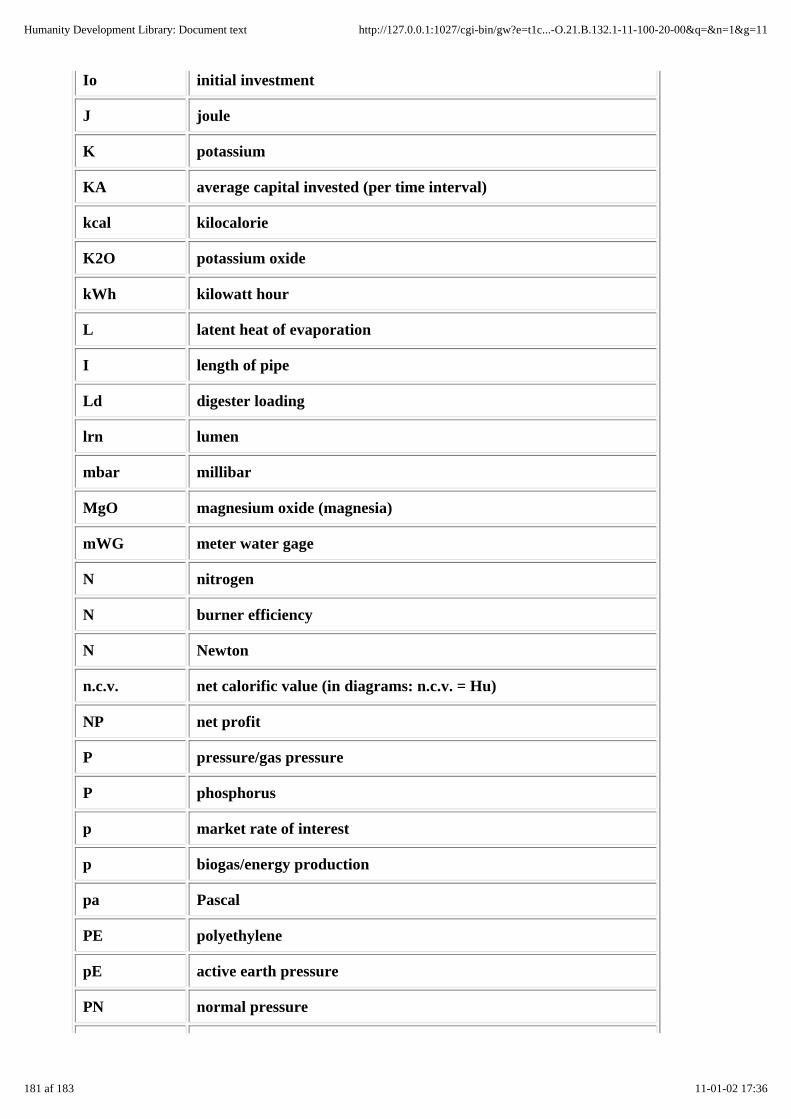
Io initial investment
J joule
K potassium
KA average capital invested (per time interval)
kcal kilocalorie
K2O potassium oxide
kWh kilowatt hour
L latent heat of evaporation
I length of pipe
Ld digester loading
lrn lumen
mbar millibar
MgO magnesium oxide (magnesia)
mWG meter water gage
N nitrogen
N burner efficiency
N Newton
n.c.v. net calorific value (in diagrams: n.c.v. = Hu)
NP net profit
P pressure/gas pressure
P phosphorus
p market rate of interest
p biogas/energy production
pa Pascal
PE polyethylene
pE active earth pressure
PN normal pressure
181 af 183 11-01-02 17:36
Humanity Development Library: Document text http://127.0.0.1:1027/cgi-bin/gw?e=t1c...-O.21.B.132.1-11-100-20-00&q=&n=1&g=11

P2O5 phosphorus pentoxide
PVC polyvinyl chloride
PW partial pressure of water vapor
pw hydrostatic pressure
Q gas flow
QW quantity of heated water
R, r radius
Re luminous efficiency
ROI return on investment (profitability)
RT retention time
Sd daily substrate input
T, t temperature
tc, max maximum consumption time
T,D.C. top dead center
tz, max maximum period of zero consumption
TN temperature under normal (s.t.p.) conditions
TS total solids content
V volume
v velocity/speed
vc maximum gas consumption
Vd digester volume
Vg gasholder volume
Vh compression volume
VN volume of biogas under normal (s.t.p.) conditions
Vn swept volume
VS volatile solids content
Vtot total volume of a cylinder
182 af 183 11-01-02 17:36
Humanity Development Library: Document text http://127.0.0.1:1027/cgi-bin/gw?e=t1c...-O.21.B.132.1-11-100-20-00&q=&n=1&g=11

W water
W watt
Wd daily water input
wE weight of dry earth
Wl water loss (leak testing)
wW weight of water
Ztot sum total of friction losses
View this page in text format
183 af 183 11-01-02 17:36
Humanity Development Library: Document text http://127.0.0.1:1027/cgi-bin/gw?e=t1c...-O.21.B.132.1-11-100-20-00&q=&n=1&g=11