biobarrier™ mbr operation and maintenance manual
TRANSCRIPT

BioBarrier™ MBR Operation and Maintenance Manual
Revision 1.3 (December 2005)
Contents 1) BioBarrier™ Introduction 2 2) System Design 2-6
2.1 Setup Inside the Tank 2 2.1.1 Installation of the BioBarrier MBR 2 BioBarrier MBR Drawing 2
2.1.2 Connection to the Control Box 3 2.2 Removal of the BioBarrier Unit 3 2.3 Control 3
2.3.1 Operating Reports/Inputs 3 2.3.1.1Normal Operation 3 2.3.1.2 Aeration Interval 3 2.3.1.3 Relax Interval 4 2.3.1.4 Sludge Removal 4 2.3.1.5 Counter for Operating Hours 4 2.3.1.6 Errors 5
2.3.2 Manual Mode 5 2.3.3 Setting Date and Clock 5
2.4 Sludge Pump 5 2.5 Blower 5 2.6 Permeate Pump 6
3) Putting Into Operation 6
3.1Conditions for Inlet 6 4) Maintenance 6
4.1 Chemical Cleaning of the Membrane 6 5) Attachments 6
System Diagram 7 Electrical Connections 8 Permeate Removal 9 Layout of the Electric Box 10 Chemical Resistance of the Membrane 11
6) BioBarrier Details
6.1 Installation 12 6.2 Operation 12
6.2.1 Starting New Filters 12 6.2.2 Continuous Operation 12-13 6.2.3 Aeration 13 6.2.4 Pause Intervals 13 6.2.5 Permeate Backflush Including the Use of Chemicals 13 6.2.6 Temperatures 13
6.3 Maintenance 13 6.4 Storage 13

Bio-Microbics, Inc. BioBarrier™ MBR Operation and Maintenance Manual 1) Introduction The Bio-Microbics MBR is a small sewage treatment plant for household applications that works as a membrane bioreactor, and is especially easy to use requiring very little maintenance. It is mounted into a tank with a particular volume, depending on the flow (see attached list). It will work for a long period of time with minimum maintenance and energy use if the following instructions for use are conformed to. In general the plant works like this: After primary treatment equipped with SaniTEE® with sedimentation of the heavy substances and separation of floatables and solids, the second tank is used as a membrane bioreactor. In this tank mixed liquor will develop, that consists of special bacteria. These bacteria remove dissolved pollutants in the water. The MBR unit removes nearly all bacteria, practically all viruses and all particles, so that the effluent from the plant is very low in BOD, TSS, ammonia-nitrogen, and fecal coliform. Since the plant works with living bacteria, the system functions on the condition that the following operating rules are obeyed. Please read this instruction manual carefully. The plant must be serviced by qualified personnel. 2) System Design > 2.1 Setup inside the Tank > 2.1.1 Installation The unit may only be mounted and put into operation by a qualified company and trained personnel. The complete unit is mounted into the tank with the pipe. The pipe is only fixed to the top of the tank. For inspection and service, the complete unit can be removed without emptying the tank. Level 1 switch (see page one, attachment) must be mounted in the upright position just below the emergency overflow of the tank. Level switch 2 must be mounted in the downward position approximately 1 foot above the tome of the MBR unit.
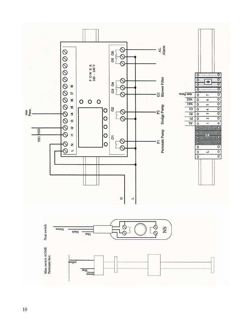
2.1.2 Connection to the Control Box Attention: High Voltage – Control box should only be opened by qualified and trained personnel. The connection to the control box is done according to the attachment, drawing 2, 3 and 4. The cables of the components permeate pump P1, sludge pump p2, blower G1, level switch1 and level switch 2 are connected according to the numbers. 2.2 Removal of the Membrane unit Removal of the complete unit can be done even if the tank is full, if the opening is big enough (approx. 28 in.). To remove the unit, the cables of the components do not have to be disconnected. For safety reasons, the electric power of the complete control box must be disconnected. The BioBarrier MBR itself can be removed from the filter housing by dismounting the three screws from the housing. 2.3 Control The MBR unit is operated with Programmable Logic Control (PLC) “Mitsubishi Alpha” of the newest generation. The program is saved as software that can be updated by your local service partner. Changes of parameters only by trained personnel! 2.3.1 Operating reports/inputs In Automatic mode, push the arrow keys “UP” and “Down” at the same time. The display then changes to the parameter menu. To scroll in the menu use the arrow keys “LEFT” and “RIGHT”. You can scroll the parameters by pushing the arrow keys “UP” and “DOWN”. Change input values as follows:
Move the cursor to the desired value by pushing the arrow keys Push “OK” (value has background now) Change value with “+” or “-“ To save the new value, push “OK”.
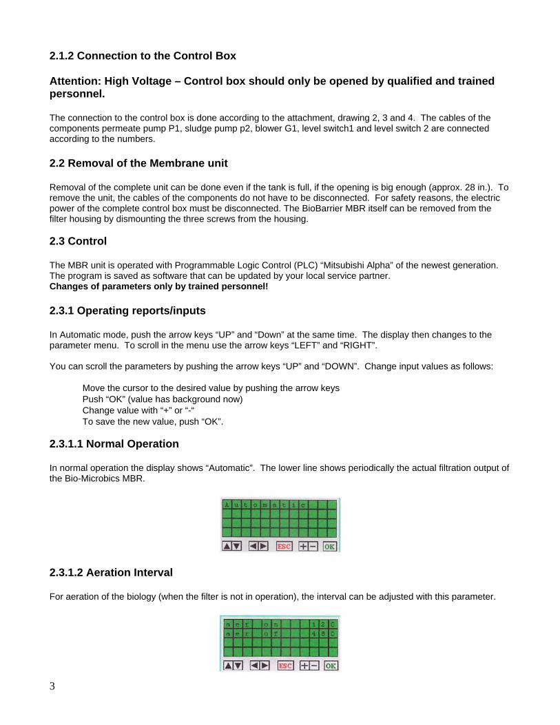
2.3.1.1 Normal Operation In normal operation the display shows “Automatic”. The lower line shows periodically the actual filtration output of the Bio-Microbics MBR.
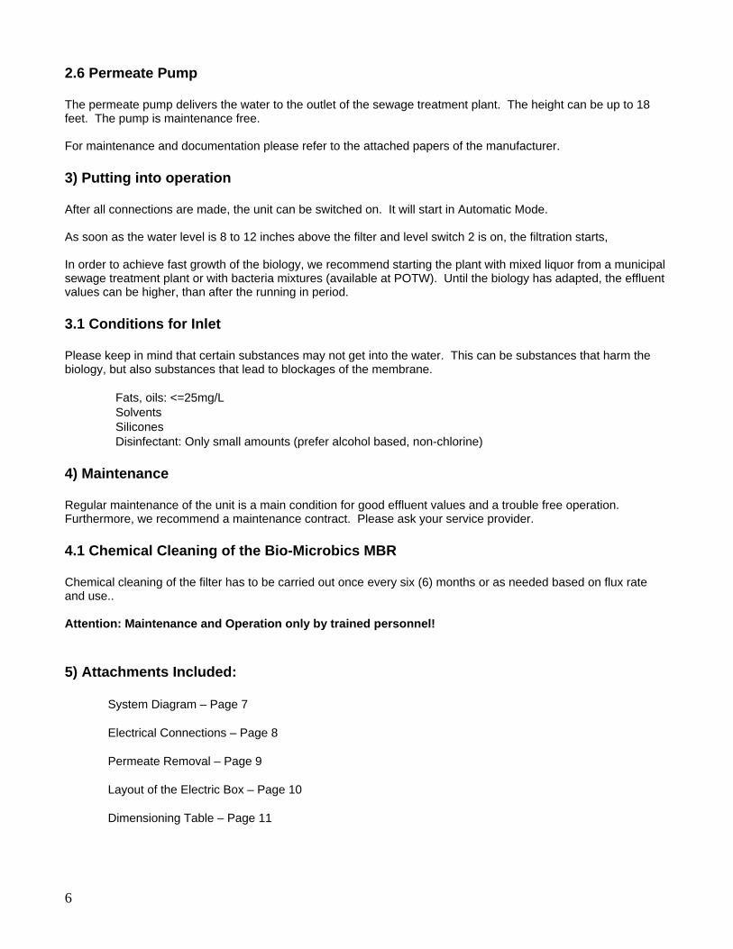
2.3.1.2 Aeration Interval For aeration of the biology (when the filter is not in operation), the interval can be adjusted with this parameter.
3

2.3.1.3 Relax Interval For the long term operation and to prevent the filter from blocking, it is sometimes advisable to have a relax interval in filtration. Every x seconds the filtration pump will be stopped for y seconds, so that there is no transmembrane pressure. The permeability rises considerably due to this cleaning effect.
The standard setting is 600 seconds on and 90 seconds off. 2.3.1.4 Sludge Removal With this option the interval for the sludge removal is defined.
For example: This display shows that the sludge pump will be switched on Friday at 6 pm and will be switched off at 6:01 pm. The sludge concentration in the biology should be 2 to 10 g/l. Especially in small sewage treatment plants, this value might be lower. The unit can operate under these conditions, but in some cases it might result in more frequent filter cleaning. To change the excess sludge timer:
Press “Arrow Down” and “Arrow Up” at the same time Press “+” (Use “Arrow down” to go to off-time) Press “OK” Use “Arrow Down” to go to 18:00 (on or off time) Change value with “+” or “-“ Press “OK” to save.
The factory setting for the running-in period is: Sludge Pump on: FR 18:00 Sludge Pump off: FR 18:01 (1 minute pumping time) 2.3.1.5 Counter for Operating Hours The total operating hours of the components are shown on this display.
4

2.3.1.6 Errors Malfunction of the unit, which leads to overflow to the emergency outlet, are signalized by the display “Alarm”. Please contact us. 2.3.2 Manual Mode For manual mode you must push the arrow keys “Left” and “Right” at the same time. You will see the following display:
To start the permeate pump manually press “OK” one time. The display shows a “1” in the right lower corner.
To start the sludge pump manually, press “OK” twice. The display shows a 2 in the right lower corner. To start the blower manually, press “OK” three times. In order to return to Automatic Mode, press “ESC”. 2.3.3 Setting Date and Clock If the unit works in automatic mode, press “OK” and “ESC” simultaneously to switch off the CPU. Then, move the cursor to the menu “Clock Set” using the arrow keys and acknowledge with “OK”. Set date and clock by pressing “+” or “-“enter with “OK”. Press “ESC”. Choose “STOP” and start the CPU by pressing “OK”. The display will show “Automatic”. 2.4 Sludge Pump With the sludge pump, mixed liquor can be pumped from the bioreactor to the first chamber. The first chamber acts as sludge storage. The sludge has to be removed approximately once per year. The pump is maintenance free. See attached documentation for an example from a typical manufacturer. 2.5 Blower The blower has two tasks. The first task is to blow air into the diffuser for the filter cleaning. The second task is to supply air for the biology. The blower has a very wear resistant, PVDF coated piston. The pump is maintenance free. See attached documentation for an example from a typical manufacturer.
5
2.6 Permeate Pump The permeate pump delivers the water to the outlet of the sewage treatment plant. The height can be up to 18 feet. The pump is maintenance free. For maintenance and documentation please refer to the attached papers of the manufacturer. 3) Putting into operation After all connections are made, the unit can be switched on. It will start in Automatic Mode. As soon as the water level is 8 to 12 inches above the filter and level switch 2 is on, the filtration starts, In order to achieve fast growth of the biology, we recommend starting the plant with mixed liquor from a municipal sewage treatment plant or with bacteria mixtures (available at POTW). Until the biology has adapted, the effluent values can be higher, than after the running in period. 3.1 Conditions for Inlet Please keep in mind that certain substances may not get into the water. This can be substances that harm the biology, but also substances that lead to blockages of the membrane.
Fats, oils: <=25mg/L Solvents Silicones Disinfectant: Only small amounts (prefer alcohol based, non-chlorine)
4) Maintenance Regular maintenance of the unit is a main condition for good effluent values and a trouble free operation. Furthermore, we recommend a maintenance contract. Please ask your service provider. 4.1 Chemical Cleaning of the Bio-Microbics MBR Chemical cleaning of the filter has to be carried out once every six (6) months or as needed based on flux rate and use.. Attention: Maintenance and Operation only by trained personnel! 5) Attachments Included:
System Diagram – Page 7
Electrical Connections – Page 8
Permeate Removal – Page 9
Layout of the Electric Box – Page 10
Dimensioning Table – Page 11
6

7 7

8

9
10

Chemical Resistance of the Bio-Microbics BioBarrier™ MBR Membrane Compatibility Chart
Group Example SP-Type Membrane
Chlorinated Solvents Methylene Chloride,Chloroform, Carbon Tetrachloride, Chlorobenzene, Trichlorothane (<1%)
--
Esters Ethyl Acetate, Butyl Acetate, Butyl Acrylate (<1%) --
Ethers Ethyl Ether, Polyethylene Oxide (<1%) --
H2O2 <2000 ppm ++
Inorganic Acids HF, HCl. H2SO4 pH 0-14
Ketones Acetone, Methyl Ethyl Ketone --
NaOCl <500 ppm, 50.000 ppmxh ++
Organic Acids Sulfamic Acid, Formic Acid, Oleic Acid, Sulfonic Acid, Acetic Acid, Acrylic Acid, Lactic Acid
pH 0-14
Phenols --
Silicones --
Alcohols Ethanol, Butanol, Isopropanol (<50%) +
Aldehydes Formaldehyde (<1%) ++
Alkalis pH 0-14
Aprotic Solvents Dimethyl Formamide, Dimethyl, Acetamide, Dioxane, N-Methyl, Pyrrolidone, Tetramethyl Acetamide
--
Aromatic Hydrocarbons Benzene, Toluene, Xylene, Anthracene, Napthalene, Gasoline --
Cellosolves Methoxyethanol, Ethoxyethanol, Buthoxyethanol ?
++ = very good - = fair + = good -- = not recommended
11

6) BioBarrier Details > 6.1 Installation The membrane elements are mounted in an upward direction into a closed frame with a size of 8.3 x 8.3 in. The aeration is from below. The connection for the filtrate is made with a suction-resistant hose (watch compatibility with chemicals, if applicable), inner diameter 1 in., and a stainless steel hose clamp. In the case of hoses that are not smooth on the inside or spiral supported material we recommend to use Loctite 5331 sealant. A tight connection is essential for the regulation of the suction pressure and the filtrate quality. When immersing the membrane into the raw water the filtrate side should be aerated in order to prevent swelling of the filter. Under no circumstance should the filtrate backflushing be carried out without the membrane elements being mounted into a closed frame (risk of damaging the membranes). Tanks for the geostatic permeate backwash must be mounted with a maximum of 28 in. above water level. The permeate backflush pressure may never exceed 28 in. of water. During backflush the membrane must be completely submerged in the water. No pumps whatsoever are allowed for permeate backflush. The raw water should comply with the attached compatibility chart. Furthermore, it must be cared for: Lipophilic substances average <25mg/L Lipophilic substances maximum <50mg/L Silicones and solvents should be avoided completely. Large molecules in general result in blocking of the membrane and should be avoided. This concerns especially flocculation aids based on polymers (polyelectrolyte) and antifoaming agents. 6.2 Operation > 6.2.1 Starting new membranes First check the function of the aeration system for the membrane scour (output of air and even distribution of bubbles). When switching on the permeate pump, the blower must start simultaneously. The membranes are soaked in glycerin, when new. After approx. 25 minutes the glycerin is washed out. During this time the output of the membrane may increase. When starting the system the transmembrane pressure should be set to 0.07 to 0.1 bars in order to prevent irreversible blocking of the membranes. After one hour the suction pressure can be increased until the design output is reached. The running in period, while a so called dirt layer develops, is terminated, when the output of the unit will only decrease over a period of a couple of days. Design output: 150 l/h These values are only average values and must be confirmed by WWS according to the application in each single case. 6.2.2 Continuous Operation Filtration Pressure: In continuous operation, the membranes are operated with a transmembrane pressure of 0.1 to 0.15 bar. The exact regulation of the suction pressure is essential for the long-term operation. An oscillating pressure should be avoided, as it leads to an early blocking of the membranes. If the application does not allow measuring the suction pressure, the output should be checked by taking the time to fill a known volume and by restricting the output to the design output.
12
Maximum suction pressure: 0.9 bar This value is technically possible, but will not be reached in the application. Generally when reaching a transmembrane pressure of 0.3 bar, a basic cleaning of the membrane is necessary. 6.2.3 Aeration In general we recommend always switching on the aeration when operating the system. The adoption of the aeration power to the required amount should be done by regulation the air flow. Air flow per membrane element with 1 layer of membranes: 3-5 scfm Air flow per membrane with 2 layers of membranes: 1.5-2.4 scfm Exceeding these values can lead to abnormal wear of the filters. 6.2.4 Relaxation Intervals In long-term trials it could be proven, that a regular, short interruption of the filtration process results in a long-lasting increase of output. For this, we recommend starting with a filtration time of 9 minutes and a pause of 30 seconds. Further optimization could lead to a filtration time of 4 minutes and a pause of 15 seconds, depending on the application. 6.2.5 Temperatures Maximum short term 50° C Maximum long term 40° C 3) Maintenance If the permeability has decreased below 50 LMH/bar, a basic cleaning of the filters is necessary (depending on the application once or twice per year). The filter must be put into a cleaning tank, in which the cleaning chemicals are filled. ATTENTION: Maintenance and Repair only to be carried out by qualified and trained personnel! Chemicals can lead to serious injuries. Always wear protective glasses and clothing. Obey the safety data sheet of the manufacturer! We recommend the basic cleaning as follows: 3 hours in NaOH, pH 11 8 hours in NaOCl, 500 ppm (calculated as free chlorine) Rinsing with tap water 1 hour in citric acid, pH 2 Temperature: 20 to 25° C Finally control the permeability with tap water. If normal value is not reached, repeat cleaning or use different detergents after contacting WWS. 4) Storage of Used Modules If the used modules with the SP-membrane have been used once, they must always stay wet. If the dismounting or storage is necessary, we recommend a basic cleaning as described above. Afterwards, the membranes can be stored, wrapped tightly into plastic sacs. The membranes filters may not be exposed to freezing temperatures or temperatures above 50°C.
13