bio gas - ceno.sattler.com
TRANSCRIPT

SATTLERCENO
BIOSTORAGEGAS

2
Wer die Umwelt als Lebensgrundlage begreift, kann nicht anders, als ihrem Schutz größte Aufmerksamkeit zu widmen.
PIONEERS FOR A CLEAN ENVIRONMENT.
Biogas storage systems actively contribute to the production of renewableenergies and thus make an important contribution to environmental protection.Future-oriented, high-quality and safety-oriented storage concepts forbiogas, substrate and digestate storage facilities have a long tradition atSattler CENO.
Sattler invented the double membrane gas holder for digester gas fromsewage treatment plants back in 1981. This storage solution has been testedand proven over decades and meanwhile has become a key component ofmodern sewage treatment plants worldwide.
The technical know-how of the Sattler CENO Research & Developmentdepartment ensures that future requirements and new areas of applicationcan be developed and implemented in a targeted manner. This expertise alsomakes it possible to develop special solutions for biogas storage togetherwith our customers. Sattler’s own weaving and coating lines ensure top quality in providing the base material, PVC-coated polyester fabrics.
It is these skills and experience that have always been incorporated into ourproducts that have helped make Sattler CENO the leading and largestsupplier of biogas, substrate and digestate storage facilities worldwide.The quality of our products ensures the highest possible investment securityas well as operational efficiency.

3
If we consider ourenvironment asour basis of life,then its protectionmust be ourhighest priority.

4
0 1 2 3 4 5 6 7 8 9 10 11 12 13 14 15 16 17 18 19 20 21 22 23 24 h
m³/
h
310
315
305
300
295
290
280
285
Gas from thestorage tank
Gas production
Gas consumption
m³
2.800
3.200
2.400
2.000
1.600
1.200
400
800
0 1 2 3 4 5 6 7 8 9 10 11 12 13 14 15 16 17 18 19 20 21 22 23 24 h
BHKW an BHKW an
1.200 m³/h 1.200 m³/h
3.200 m³
2.900 m³
500 m³
200 m³
Storage fill level
Gas consumption cogeneration unit
m³
2.800
3.200
2.400
2.000
1.600
1.200
400
800
0 1 2 3 4 5 6 7 8 9 10 11 12 13 14 15 16 17 18 19 20 21 22 23 24 h
Cogeneration
unit on
1.200 m³/h 1.200 m³/h
3.200 m³
2.900 m³
500 m³
200 m³
Cogeneration
unit on
THE PERFECT SOLUTION FOR EVERY CHALLENGE.
WHICH VOLUME DO I CHOOSE?
Storage tanks are designed to compensate for fluctuations in production and consumption, for volume changes due to varyingtemperatures and for stagnating consumption; furthermore, gas holders store gas for later use. With these parameters theoptimal dimensioning can be determined. The ideal storage volume varies according to the plant design, the substrate mixture,and the management of the plant.
BASE LOAD OPERATION
The goal is to enable consumers to operate at high capacity. Consumers’ performance should neither be influenced nor determinedby fluctuating gas production but should constantly operate at a defined load. Flaring excess gas should be avoided.Therefore, excess gas production is buffer stored and lack of gas production is replaced by the stored gas to cover the demand.Conventional storage tanks hold volumes corresponding to a gas production of three to four hours.
PEAK LOAD IN FLEX MODE
The storage tank serves to balance out the continuous gas production and the discontinuous consumption. Low gas productionwill be stored over a long period of time, followed by a short but high-powered consumption period. That is why bigger storagetanks are required.
5
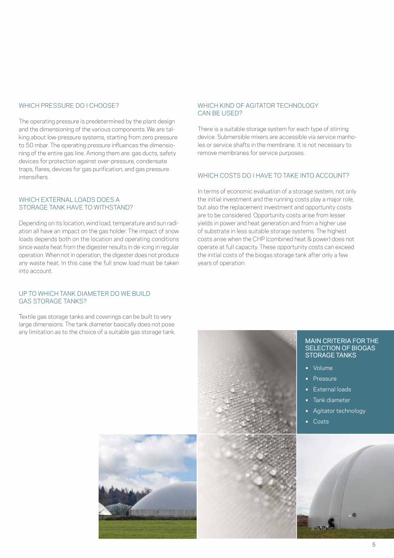
• Volume
• Pressure
• External loads
• Tank diameter
• Agitator technology
• Costs
Storage fill level
WHICH PRESSURE DO I CHOOSE?
The operating pressure is predetermined by the plant design and the dimensioning of the various components. We are tal-king about low-pressure systems, starting from zero pressure to 50 mbar. The operating pressure influences the dimensio-ning of the entire gas line. Among them are: gas ducts, safety devices for protection against over-pressure, condensate traps, flares, devices for gas purification, and gas pressure intensifiers.
WHICH EXTERNAL LOADS DOES ASTORAGE TANK HAVE TO WITHSTAND?
Depending on its location, wind load, temperature and sun radi-ation all have an impact on the gas holder. The impact of snow loads depends both on the location and operating conditions since waste heat from the digester results in de-icing in regular operation. When not in operation, the digester does not produce any waste heat. In this case the full snow load must be taken into account.
UP TO WHICH TANK DIAMETER DO WE BUILD GAS STORAGE TANKS?
Textile gas storage tanks and coverings can be built to very large dimensions. The tank diameter basically does not pose any limitation as to the choice of a suitable gas storage tank.
WHICH KIND OF AGITATOR TECHNOLOGY CAN BE USED?
There is a suitable storage system for each type of stirring device. Submersible mixers are accessible via service manho-les or service shafts in the membrane. It is not necessary to remove membranes for service purposes.
WHICH COSTS DO I HAVE TO TAKE INTO ACCOUNT?
In terms of economic evaluation of a storage system, not only the initial investment and the running costs play a major role, but also the replacement investment and opportunity costs are to be considered. Opportunity costs arise from lesser yields in power and heat generation and from a higher use of substrate in less suitable storage systems. The highest costs arise when the CHP (combined heat & power) does not operate at full capacity. These opportunity costs can exceed the initial costs of the biogas storage tank after only a few years of operation.
MAIN CRITERIA FOR THE SELECTION OF BIOGAS STORAGE TANKS

6
The double membrane gas
storage as a key component of
any efficient biogas plant.

7
A
I
B
C
D
H
GE
F
7
• High operating pressures
• Suitable for high snow and wind loads
• Permanently gas-tight
• Low investment and running costs
• Short construction time
• High reliability
• Accurate level metering
• Low maintenance costs
• Uniform air intake via the AIRFLOW-SYSTEMTM
A Outer membrane B Inner membrane C AIRFLOW-SYSTEMTM D Air regulation valve E Support air blower F Anchor ring G Safety valve H Inspection window I Level meter
DOUBLE MEMBRANEGAS STORAGEFREESTANDINGThe freestanding double membrane gas holder consists of a formative outer membrane and of an internal and a bottom membrane forming the actual gas space. A permanently running support air blower provides air to the space between the membranes to keep the pressure constant – balancing a possible inflow or outflow of gas. The pressurized air keeps the outer membrane in shape and allows the gas holder to with-stand external loads. At the same time, the inner membrane is put under pressure and gas is pushed into the gas ducts.
A widely visible trademark of the Sattler double membranegas holder is the patented AIRFLOW-SYSTEMTM. It ensures a uniform air intake across the height of the gas holder. Laser measurement is preferably used to determine the filling level inside the tank. To improve measurement accuracy, the inner membrane is manufactured as to ensure reproducible membrane movement.
FEATURES:

8
AB
D IC
F
GE H
J
DOUBLE MEMBRANE GAS STORAGE TANK-MOUNTED
• High operating pressures
• High volumes up to a hemispherical shape
• Suitable for high snow and wind loads
• Permanently gas-tight
• Low investment and running costs
• Short construction time
• High reliability
• Uniform air intake via the AIRFLOW-SYSTEMTM
• Various fittings possible
FEATURES:
The tank-mounted double membrane gas holder consists of an outer membrane and an inner membrane that seals the fer-mentation space gas-tight. The outer membrane is reinforced by a support air blower. This is to maintain the internal pressure at a constant level and to ensure to withstand wind and other outer forces (loads).
Much like the freestanding DMGS this gas holder type also uses the patented AIRLFOW-SYSTEMTM. Both membranes are anchored to the crown or to the outer wall of the steel or con-crete tank using clamping rails with a positive and non-positive fitting. The positive fitting is secured by a rope welded into the outer rim of the membrane.
The substructure prevents the inner membrane from touching the substrate and being destroyed by the agitators. The belt- structure and central pole are designed to withstand the re-quired loads. Filling levels are measured by means of hydraulic measurement systems. Various openings ensure the perfect operation and servicing.
A Outer membrane B Inner membrane C AIRFLOW-SYSTEMTM D Brace system E Anchor ring F Air regulation valve G Support air blower H Safety valve I Inspection window J Level meter
9
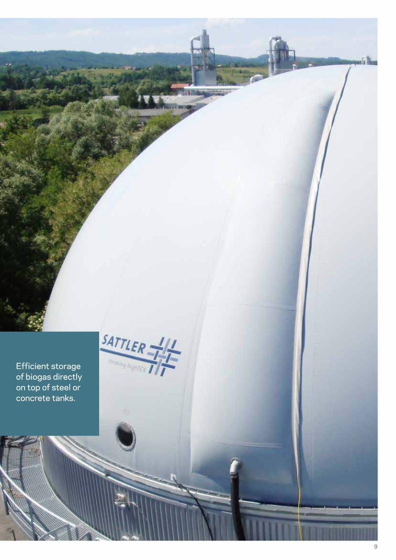
Efficient storage of biogas directly on top of steel or concrete tanks.

10
MOBILE GAS STORAGE FOR RENT
During repair or modification works at the gas storage plants, there is often the need for a temporary option for the storage of biogas.
The lack of a temporary storage alternative leads to limitations in the flexibility of the plant and is also related to inevitable major financial losses. Moreover, lacking a temporary reliable storage system entails the risk of biogas or methane release taking place, an issue that should not take place and not only for ecological reasons.
Sattler CENO‘s mobile gas storage for rent is designed as a horizontal double membrane gas storage. It offers operational safety at the plant and allows the operation of a cogene-ration plant also during inspections or modifications of the gas storages.
Compact. For rent. Safe.
• Individual rental period
• Quickly available
• Plug-and-Play
• Adjustable operating pressure
• Standard road transport
FEATURES:
ALL THE BENEFITS OF THE MOBILE GAS HOLDER FOR RENTAL AT A GLANCE:
• Undisturbed operation of the plant during overhauling or inspections.
• No unnecessary expenses for special transport: The complete system fits on a semi-trailer
• No additional devices are required for the connections: All signals are placed in a cabinet

11
The perfect solution for temporary gas storage.

12
Classical mast-supported
tank coverings, with and without storage function.

13
AB
C
D
EThe single-shell tank-top biogas roof consists of an outer membrane resting on a central pillar. This allows the biogas roof to withstand external forces, such as snow, rain, wind loads etc. The biaxial curvature of the surface prevents the roof from fluttering and pumping in the wind. The membrane is fastened to the top of steel or concrete tanks in order to form a gas-tight sealing. Safety valves secure the covering against over- or underpressure on the gas side. The double-shell biogas roof is a mast-supported tank cover consisting of an inner membrane forming the actual gas space. Similar to a tent, the outer membrane is stretched between the central pillar and the outer edge of the tank. This ensures an even pretension of the membrane and a reduced wear and tear around the edge of the tank.
A Outer membrane B Central pillar C Anchor ring D Service opening E Safety valve
• Mast-supported system
• Depressurized covering
• Blow-off pressure up to 2 mbar
• Combines storage and cover functions
• Stagle due to biaxial curvature
• High reliability
• Suitable for high snow and wind loads
• Permanently gas-tight
FEATURES:
BIOGAS ROOF

14
Ideal solution for low-emission
tank coverings.

15
• High stability
• Covering approved to comply with building law and safety requirements
• Corrosion-proof, non-putrescible materials
• Prevention of odour emissions
• Manholes ensuring accessibility from every position
• Easy and safe to operate
• Specially designed mounting system
FEATURES:
SILO ROOF
The tank-top silo roof helps prevent emissions and the contamination of fer-mentation residues with rainwater. It offers the ideal solution for low-emis-sion tank coverings. The roof has been designed to withstand extreme wind loads as well as snow and water loads. Its material-specific design has led to a characteristic shape. It prevents the roof from fluttering and pumping with the wind while also reducing material fatigue. Due to the very low level of emissions, it is also a great contribution to a cleaner environment.
The silo roof is distinguished by a highly sophisticated multi-functional design, which makes it the ideal solution for agriculture and for sewage treatment as well as biogas plants.
16
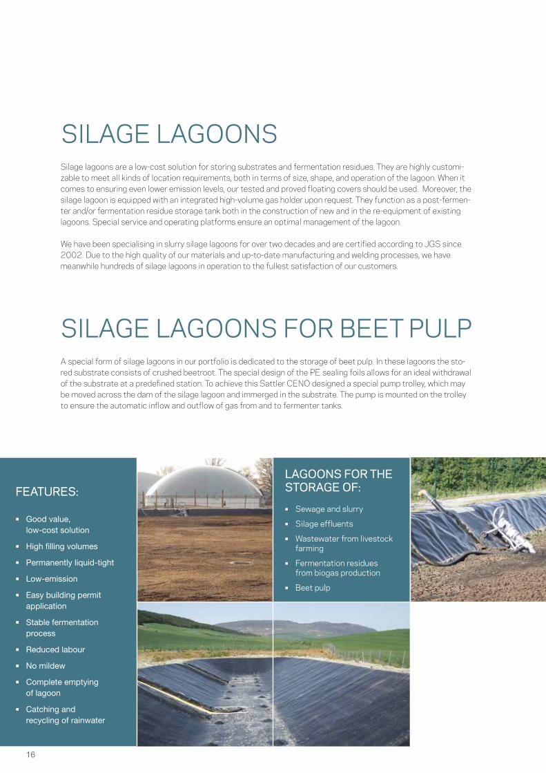
SILAGE LAGOONS FOR BEET PULP
• Good value, low-cost solution
• High filling volumes
• Permanently liquid-tight
• Low-emission
• Easy building permit application
• Stable fermentation process
• Reduced labour
• No mildew
• Complete emptying of lagoon
• Catching and recycling of rainwater
FEATURES:
Silage lagoons are a low-cost solution for storing substrates and fermentation residues. They are highly customi-zable to meet all kinds of location requirements, both in terms of size, shape, and operation of the lagoon. When it comes to ensuring even lower emission levels, our tested and proved floating covers should be used. Moreover, the silage lagoon is equipped with an integrated high-volume gas holder upon request. They function as a post-fermen-ter and/or fermentation residue storage tank both in the construction of new and in the re-equipment of existing lagoons. Special service and operating platforms ensure an optimal management of the lagoon.
We have been specialising in slurry silage lagoons for over two decades and are certified according to JGS since 2002. Due to the high quality of our materials and up-to-date manufacturing and welding processes, we have meanwhile hundreds of silage lagoons in operation to the fullest satisfaction of our customers.
A special form of silage lagoons in our portfolio is dedicated to the storage of beet pulp. In these lagoons the sto-red substrate consists of crushed beetroot. The special design of the PE sealing foils allows for an ideal withdrawal of the substrate at a predefined station. To achieve this Sattler CENO designed a special pump trolley, which may be moved across the dam of the silage lagoon and immerged in the substrate. The pump is mounted on the trolley to ensure the automatic inflow and outflow of gas from and to fermenter tanks.
• Sewage and slurry
• Silage effluents
• Wastewater from livestock farming
• Fermentation residues from biogas production
• Beet pulp
SILAGE LAGOONS
LAGOONS FOR THE STORAGE OF:
17
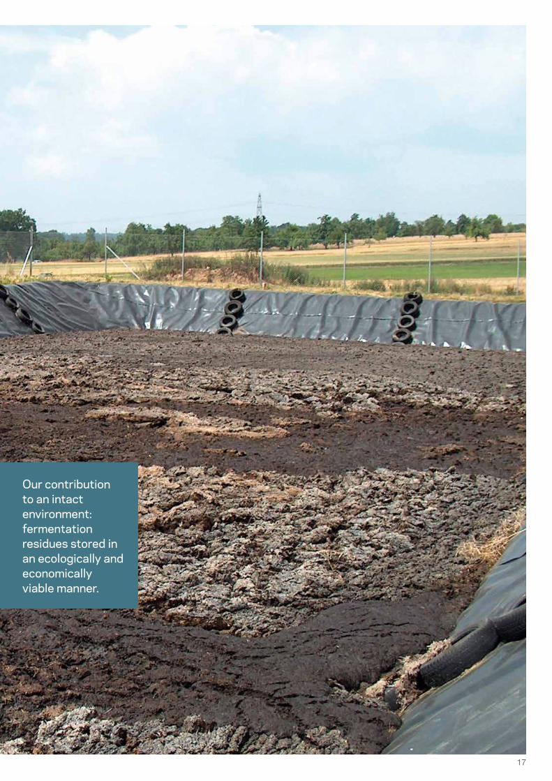
Our contribution to an intact environment: fermentation residues stored in an ecologically and economically viable manner.
18
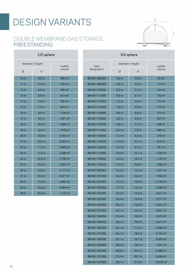
ØH
3/4 sphere
typedesignation
diameter / heightusablevolume
Ø H
BA100 108/205 5,0 m 3,8 m 53 m³
BA100 109/205 5,6 m 4,2 m 73 m³
BA100 110/205 6,2 m 4,7 m 104 m³
BA100 111/205 6,8 m 5,1 m 132 m³
BA100 112/205 7,4 m 5,6 m 174 m³
BA100 113/205 7,9 m 5,9 m 213 m³
BA100 114/205 8,6 m 6,5 m 275 m³
BA100 115/205 9,2 m 6,9 m 337 m³
BA100 116/205 9,8 m 7,4 m 408 m³
BA100 117/205 10,4 m 7,8 m 488 m³
BA100 118/205 11,0 m 8,3 m 578 m³
BA100 119/205 11,6 m 8,7 m 679 m³
BA100 116/250 12,2 m 9,1 m 791 m³
BA100 117/250 13,3 m 10,1 m 1.046 m³
BA100 118/250 14,0 m 10,5 m 1.197 m³
BA100 119/250 14,6 m 10,9 m 1.362 m³
BA100 120/250 15,3 m 11,3 m 1.541 m³
BA100 121/250 16,4 m 12,4 m 1.933 m³
BA100 122/250 17,0 m 12,8 m 2.158 m³
BA100 123/250 17,7 m 13,2 m 2.400 m³
BA100 124/250 18,3 m 13,5 m 2.641 m³
BA100 125/250 19,4 m 14,6 m 3.217 m³
BA100 126/250 20,0 m 15,0 m 3.531 m³
BA100 127/250 20,7 m 15,4 m 3.841 m³
BA100 128/250 21,8 m 16,5 m 4.575 m³
BA100 129/250 22,4 m 16,9 m 4.971 m³
BA100 130/250 23,1 m 17,3 m 5.390 m³
BA100 127/300 24,2 m 18,0 m 6.184 m³
BA100 128/300 25,1 m 18,7 m 6.923 m³
BA100 129/300 26,0 m 19,3 m 7.641 m³
BA100 130/300 26,9 m 20,0 m 8.489 m³
BA100 131/300 27,8 m 20,7 m 9.398 m³
BA100 132/300 28,7 m 21,3 m 10.275 m³
1/2 sphere
diameter / heightusablevolume
Ø H
10 m 5,0 m 285 m³
11 m 5,5 m 376 m³
12 m 6,0 m 485 m³
13 m 6,5 m 613 m³
14 m 7,0 m 762 m³
15 m 7,5 m 934 m³
16 m 8,0 m 1.130 m³
17 m 8,5 m 1.351 m³
18 m 9,0 m 1.599 m³
19 m 9,5 m 1.876 m³
20 m 10,0 m 2.184 m³
21 m 10,5 m 2.523 m³
22 m 11,0 m 2.892 m³
23 m 11,5 m 3.296 m³
24 m 12,0 m 3.735 m³
25 m 12,5 m 4.207 m³
26 m 13,0 m 4.717 m³
27 m 13,5 m 5.271 m³
28 m 14,0 m 5.862 m³
29 m 14,5 m 6.494 m³
30 m 15,0 m 7.178 m³
DESIGN VARIANTS
DOUBLE MEMBRANE GAS STORAGE FREESTANDING

19
Ø
H
H
Ø
* Abhängig von der Membranwahl
1/4 sphere 1/2 sphere
diameter/ height above the tank usable
volume
diameter/ height above the tank usable
volumeØ H Ø H
10 m 2,5 m 129 m³ 10 m 5,0 m 285 m³
11 m 2,8 m 172 m³ 11 m 5,5 m 376 m³
12 m 3,0 m 216 m³ 12 m 6,0 m 485 m³
13 m 3,3 m 276 m³ 13 m 6,5 m 613 m³
14 m 3,5 m 336 m³ 14 m 7,0 m 762 m³
15 m 3,8 m 415 m³ 15 m 7,5 m 934 m³
16 m 4,0 m 493 m³ 16 m 8,0 m 1.130 m³
17 m 4,3 m 594 m³ 17 m 8,5 m 1.351 m³
18 m 4,5 m 693 m³ 18 m 9,0 m 1.599 m³
19 m 4,8 m 819 m³ 19 m 9,5 m 1.876 m³
20 m 5,0 m 940 m³ 20 m 10,0 m 2.184 m³
21 m 5,3 m 1.094 m³ 21 m 10,5 m 2.523 m³
22 m 5,5 m 1.237 m³ 22 m 11,0 m 2.892 m³
23 m 5,8 m 1.417 m³ 23 m 11,5 m 3.296 m³
24 m 6,0 m 1.589 m³ 24 m 12,0 m 3.735 m³
25 m 6,3 m 1.793 m³ 25 m 12,5 m 4.207 m³
26 m 6,5 m 1.985 m³ 26 m 13,0 m 4.717 m³
27 m 6,8 m 2.230 m³ 27 m 13,5 m 5.271 m³
28 m 7,0 m 2.450 m³ 28 m 14,0 m 5.862 m³
29 m 7,3 m 2.724 m³ 29 m 14,5 m 6.494 m³
30 m 7,5 m 2.981 m³ 30 m 15,0 m 7.178 m³
31 m 7,8 m 3.285 m³
32 m 8,0 m 3.567 m³
33 m 8,3 m 3.908 m³
34 m 8,5 m 4.233 m³
35 m 8,8 m 4.645 m³
36 m 9,0 m 4.976 m³
37 m 9,3 m 5.423 m³
38 m 9,5 m 5.800 m³
39 m 9,8 m 6.269 m³
40 m 10,0 m 6.710 m³
23°
diameter/ height above the tank usable
volumeØ H
10 m 2,1 m 59 m³
11 m 2,3 m 79 m³
12 m 2,5 m 104 m³
13 m 2,8 m 118 m³
14 m 3,0 m 145 m³
15 m 3,2 m 171 m³
16 m 3,4 m 198 m³
17 m 3,6 m 236 m³
18 m 3,8 m 281 m³
19 m 4,0 m 326 m³
20 m 4,2 m 373 m³
21 m 4,5 m 426 m³
22 m 4,7 m 487 m³
23 m 4,9 m 555 m³
24 m 5,1 m 630 m³
25 m 5,3 m 686 m³
26 m 5,5 m 772 m³
27 m 5,7 m 889 m³
28 m 5,9 m 990 m³
29 m 6,2 m 1.077 m³
30 m 6,4 m 1.151 m³
31 m 6,6 m 1.260 m³
32 m 6,8 m 1.403 m³
33 m 7,0 m 1.551 m³
34 m 7,2 m 1.706 m³
35 m 7,4 m 1.929 m³
36 m 7,6 m 2.098 m³
37 m 7,9 m 2.278 m³
38 m 8,1 m 2.468 m³
39 m 8,3 m 2.668 m³
40 m 8,5 m 2.877 m³
BIOGAS ROOF
DOUBLE MEMBRANEGAS STORAGETANK-MOUNTED

SATTLERCENO
Am Eggenkamp 14, 48268 Greven, Germany
T +49 2571 969 200F +49 2571 969 1199 E [email protected]
Sattler Ceno TOP-TEX GmbH
ceno.sattler.com
© S
attle
r C
eno
TOP
-TE
X G
mb
H |
2020
EN
1.0