bimm ep aus models · bimm ep aus models mechanical piping ... the associated specification for...
TRANSCRIPT

���� BIM�MEPAUS MODELS
Mechanical Piping Services Specification
Issued By: BIM�MEPAUS
30 Cromwell Street, Burwood 3205 VIC Australia
Revision: 0
Date October 2014

BIM�MEPAUS
Mechanical Piping Services Specification
BIM�MEPAUS
Page 2 October 2014 REV 0
Acknowledgements BIM�MEP
AUS acknowledges the contributions of those organisations involved in the development and review of
this document including principal contributors:
• AECOM
• A.G. Coombs � Projects
• Antec
• Arup
• Autodesk
• D&E Air conditioning
• Fagersta
• Hansen & Yuncken
• Lend Lease
• Norman Disney & Young
• OneSteel
• Reece
• Rayson Industries
• Victaulic
• Watson Fitzgerald & Associates
Formatting conventions In addition to standard text formatting for Section and Clause Headings, Table Headings, etc the table below
shows other text formats that are used in BIM�MEPAUS
Standards and reference documents and their application:
Text Type Example Indicates
Normal italicized text BIM Execution Plan The generic title for a type of document.
Bold italicised text BIM�MEPAUS
Specification The name of a specific referenced document or
standard or term.
Dark red text LOD First reference to a term or abbreviation that is
defined in the BIM�MEPAUS
website glossary
under Practices
Blue text www.bimmepaus.com.au Hyperlink / weblink
Blue italicised text Explanatory notes Specification explanatory notes or reference
information.
Green text Future Develop This indicates sections or requirements which are
still under development but planned to be included
within BIM�MEPAUS
.
Keeping BIM-MEPAUS
Up-to-date BIM�MEP
AUS software and model content is regularly updated to reflect changes in legislation, technology and
industry practice. Feedback and suggestions in relation to the standards via the BIM�MEPAUS
website are
welcome. Updates to software and content are managed and delivered through the BIM�MEPAUS
website to
registered BIM�MEPAUS
users.
Liability Disclaimer
BIM�MEPAUS
makes no warranty, expressed or implied, including but not limited to any implied warranties of
merchantability and fitness for a particular purpose, nor assumes any legal liability or responsibility for the
accuracy, completeness, or usefulness of the information in this document.
In no event shall BIM�MEPAUS
or its agents be liable for damages or losses resulting from your use of, or reliance
on the information provided in this document.
COPYRIGHT © BIM�MEP
AUS
All rights reserved.

BIM�MEPAUS
Mechanical Piping Services Specification
BIM�MEPAUS
Page 3 October 2014 REV 0
Table of Contents
1 INTRODUCTION ................................................................................................................. 4
1.1 Scope ........................................................................................................................................................ 4
1.2 References ................................................................................................................................................ 4
1.3 Objectives .................................................................................................................................................. 4
2 PIPING MODEL WORKFLOW ............................................................................................ 5
2.1 Model workflow .......................................................................................................................................... 5
2.2 Systems, Services and Specifications ....................................................................................................... 5
2.3 Service Naming Convention ...................................................................................................................... 5
2.4 System Schematic ..................................................................................................................................... 7
2.5 Design Model ............................................................................................................................................ 7
2.6 Construction Model.................................................................................................................................... 7
3 PIPEWORK SYSTEMS ....................................................................................................... 8
3.1 System Designation and Colour ................................................................................................................ 8
3.2 Uniformat Classification ............................................................................................................................. 8
4 PIPING STANDARDS ......................................................................................................... 9
5 PIPING SPECIFICATIONS ............................................................................................... 11
5.1 Specification Development Framework ................................................................................................... 11
5.2 Pipe and Tube Specification .................................................................................................................... 11
5.3 Temperature Constraints ......................................................................................................................... 11
5.4 BIM�MEPAUS
Temperature Classification ................................................................................................. 12
5.5 Pressure Constraints ............................................................................................................................... 12
5.6 BIM�MEPAUS
Pipe Specifications ............................................................................................................. 14
6 PIPING SYSTEM FAMILIES ............................................................................................. 15
6.1 Pipe / Fitting Sizes ................................................................................................................................... 15
6.2 Fabrication Accuracy ............................................................................................................................... 16
6.3 Pipe /Tube Parameters ............................................................................................................................ 16
6.4 Standard Jointing Methods ...................................................................................................................... 16
6.5 Standard Fittings ..................................................................................................................................... 16
6.6 Fitting parameters .................................................................................................................................... 17
6.7 Pipe Equipment ....................................................................................................................................... 17
6.8 Pipe Equipment Parameters .................................................................................................................... 17
7 FOUNDATION PIPING SPECIFICATIONS ...................................................................... 18
8 BIM�MEPAUS TEMPLATE PIPING SERVICES .................................................................. 20
9 PIPING INSULATION ........................................................................................................ 21
ANNEXURE A – PIPING PRACTICE REVIEW
ANNEXURE B – PIPE HANGER PRACTICE REVIEW

BIM�MEPAUS
Mechanical Piping Services Specification
BIM�MEPAUS
Page 4 October 2014 REV 0
1 INTRODUCTION
1.1 Scope
This document sets out the BIM�MEPAUS
technical specification and modelling workflows for mechanical services
piping and insulation.
Excluded from the current specification and BIM�MEPAUS
template are:
• Seismic restraints;
• Vertical pipe supports;
• Fabricated pipe brackets and pipe stands; and
• Anchoring and expansion systems.
These components of the model require detailed engineering design that is beyond the scope of the current BIM�
MEPAUS
template.
These systems and components are planned for future development:
• High pressure / high temperature systems including steam;
• Spiral Welded Stainless Steel Tube to ASTM A778
• Medical Gases;
• Refrigerant Piping;
• ABS and uPVC pressure services; and
• Pipe hangers for defined applications.
1.2 References
This specification should be read in conjunction with the following documents that provide the supporting
framework for specification and modelling of mechanical services piping systems:
• BIM�MEPAUS
Waterside Systems, Plant and Equipment Schedule – this Excel based schedule
provides the complete listing for all piping systems, plant and equipment names as well as designation of
piping system colours; and
• BIM�MEPAUS
Master Shared Parameter Schedule – this document provides the source for all shared
parameter names used within the BIM�MEPAUS
IFM and MCM models – this Excel formatted schedule
can be referenced to obtain the classification of each parameter as well as its associated GUID.
These documents can be accessed through the BIM�MEPAUS
website.
1.3 Objectives
This specification defines the BIM�MEPAUS
modelling standards and approach to mechanical services piping
systems. Benefits sought from the implementation of the standard include:
• A unified and structured approach to piping and insulation service specification and modelling;
• Reliable piping Design�to�Fabrication and Design�to�Commissioned As�Built workflows;
• A library of constructible piping services within the BIM�MEPAUS
template that meet the majority of project
design and construction requirements;
• The ability to complete a range of design analysis and engineering calculations; and
• Efficient pipework cost take�off.

BIM�MEPOctober 2014 REV 0
2 PIP
2.1 Model workflow
This standard is based on implementation of the
continuous development of
is able to
With the development of the
and engineering
400 model.
The Commissioned As
modifications
cycle.
2.2 Systems, Services and Specifications
A key feature of the
specifications
full potential of
Systems
Gas System
Services
Specification
In BIM�MEP
piping and insulation
respect to
The BIM�
preferences
2.3 Service Naming Convention
The BIM�
• A
• System
• Service specification
The displayed short form name of the service
of options
• Author_
The supporting
• A
MEPAUS
October 2014 REV 0
PIPING MODEL
Model workflow
This standard is based on implementation of the
continuous development of
is able to effectively support
With the development of the
and engineering design checks, scheduling, pip
model.
he Commissioned As
modifications to the installation
Systems, Services and Specifications
A key feature of the BIM
specifications. This approach draw
full potential of constructible
Systems define the
Gas System, etc.
Services set the
Specification
MEPAUS
the system and
piping and insulation
respect to downstream
�MEPAUS
template
preferences and pipe segments to allow designers and engineers to model efficiently
Service Naming Convention
�MEPAUS
piping service naming convention
Author
System
Service specification
The displayed short form name of the service
of options for each system
Author_System
supporting service
Author_ System
MODEL
Model workflow
This standard is based on implementation of the
continuous development of the MEP
support life cycle management of the building
With the development of the BIM�MEP
design checks, scheduling, pip
he Commissioned As�Built Model
to the installation allowing an accurate as
Systems, Services and Specifications
BIM�MEPAUS
approach to pipework modelling is the use of
This approach draw
constructible Revit MEP modelling
define the type of
, etc.
the piping type and routing preferences
Specifications detail the construction standards
system and service must be selected
piping and insulation specification
downstream system engineering validation, coordination and scheduling take
template provides the piping services tha
and pipe segments to allow designers and engineers to model efficiently
Service Naming Convention
piping service naming convention
Service specification.
The displayed short form name of the service
for each system type. The service name syntax is:
System_Safe Working Pres
service specification
System _Safe Working Pressure_
WORKFLOW
This standard is based on implementation of the
MEP model through
life cycle management of the building
MEPAUS
constructible
design checks, scheduling, pipework spooling and procurement
Built Model can provide
allowing an accurate as
Systems, Services and Specifications
approach to pipework modelling is the use of
This approach draws from the Autodesk
Revit MEP modelling
type of reticulation system:
piping type and routing preferences
detail the construction standards
service must be selected
specifications. The use of this modelling approach provides significant benefits with
system engineering validation, coordination and scheduling take
provides the piping services tha
and pipe segments to allow designers and engineers to model efficiently
Service Naming Convention
piping service naming convention
The displayed short form name of the service allows the required
. The service name syntax is:
_Safe Working Pressure_Material_Jointing Method.
specification syntax is:
_Safe Working Pressure_
WORKFLOW
This standard is based on implementation of the Design to Commissioned As
through the project
life cycle management of the building
constructible Revit
ework spooling and procurement
can provide the basis for
allowing an accurate as�built model to be main
Systems, Services and Specifications
approach to pipework modelling is the use of
the Autodesk Fabrication a
Revit MEP modelling workflows are
reticulation system: Chilled Water System, Heating W
piping type and routing preferences.
detail the construction standards and details for each
service must be selected to
The use of this modelling approach provides significant benefits with
system engineering validation, coordination and scheduling take
provides the piping services that incorporate pipe types with their associated
and pipe segments to allow designers and engineers to model efficiently
piping service naming convention syntax comprises
allows the required
. The service name syntax is:
sure_Material_Jointing Method.
_Safe Working Pressure_ Material Spec
Mechanical Piping Services Specification
Design to Commissioned As
project delivery to provide
life cycle management of the building services installation
Revit modelling template it is
ework spooling and procurement
basis for the design and documentation of
built model to be main
approach to pipework modelling is the use of
Fabrication approach to modelling and is important if the
are to be leveraged by designers and constructors.
Chilled Water System, Heating W
and details for each
to model the system and
The use of this modelling approach provides significant benefits with
system engineering validation, coordination and scheduling take
t incorporate pipe types with their associated
and pipe segments to allow designers and engineers to model efficiently
syntax comprises three key
allows the required service to be selected
sure_Material_Jointing Method.
Specification_Jointing Method_Size Range.
chanical Piping Services Specification
Design to Commissioned As�Built
delivery to provide a completed
installation.
modelling template it is planned
ework spooling and procurement will occur
design and documentation of
built model to be maintained through the building’s life
approach to pipework modelling is the use of pipework systems, services and
pproach to modelling and is important if the
to be leveraged by designers and constructors.
Chilled Water System, Heating W
and details for each pipe type.
model the system and nominate
The use of this modelling approach provides significant benefits with
system engineering validation, coordination and scheduling take�offs.
t incorporate pipe types with their associated
and pipe segments to allow designers and engineers to model efficiently and effectively
key components:
to be selected from the available range
_Jointing Method_Size Range.
BIM
chanical Piping Services Specification
workflow that see
completed as�built mode
planned that all
occur off the Revit MEP
design and documentation of any future
through the building’s life
systems, services and
pproach to modelling and is important if the
to be leveraged by designers and constructors.
Chilled Water System, Heating Water System, Natur
nominate the
The use of this modelling approach provides significant benefits with
offs.
t incorporate pipe types with their associated
and effectively.
components:
from the available range
_Jointing Method_Size Range.
BIM�MEPAUS
chanical Piping Services Specification
Page 5
that sees the
built model that
that all system
the Revit MEP LOD
any future
through the building’s life
systems, services and
pproach to modelling and is important if the
to be leveraged by designers and constructors.
ater System, Natural
the required
The use of this modelling approach provides significant benefits with
t incorporate pipe types with their associated routing
from the available range
_Jointing Method_Size Range.

BIM�MEPAUS
Mechanical Piping Services Specification
BIM�MEPAUS
Page 6 October 2014 REV 0
2.3.1 Service Types
There are three types of services within the BIM�MEPAUS
scheme:
• Design services provided with the template;
• Manufacturer content based services pre�built from BIM�MEPAUS
manufacturer content; and
• User defined services that are BIM�MEPAUS
compliant and generally combine design and/or
manufacturer content based services to meet specification and installation preferences.
Design Services
A number of Design Services are provided in the BIM�MEPAUS
template for each system type that offer a range of
working pressures and material choices.
Examples of design services offered within the template include:
• BMA_CHW�F_1400kPa_CopperTypeB_Brazed_CarbonSteelAPI5L_Welded
• BMA_CHW�R_1400kPa_CopperTypeB_Brazed_CarbonSteelAPI5L_Welded
The associated specification for this Design Service is:
• BMA_CHW�F_2100kPa_CopperTypeB_Brazed_DN15�40_CarbonSteelAPI5LSTDWT_Welded_DN50�600
Manufacturer Content Based Services
BIM�MEPAUS
hosted manufacturer certified content is provided as both component families and complete
services:
An example of such a service could be a 2100kPa HHW service incorporating Carbon Steel Piping and Victaulic®
roll groove fittings:
• BMA_HHW�F_2100kPa_CarbonSteel_VictaulicEPDM
The associated specification for this Manufacturer Content Service could be:
• BMA_HHW�F_2100kPa_CarbonSteelAPI5LSTDWT_VictaulicEPDM_DN50�600
User Defined Services
BIM�MEPAUS
compliant hybrid services are developed by users and may be added to the template to allow
organizations to incorporate their preferences in relation to materials and jointing selections.
An example, of a company specific service to achieve a higher pressure rating and alternative carbon steel
specification is as follows:
• AGC_HHW�F_2100kPa_CopperTypeB_BPressEPDM_CarbonSteeAPI5LSCH40_VictaulicEPDM
The associated specification for this service could be:
• AGC_HHW�F_2100kPa_CopperTypeB_B�PressEPDM_DN15�40_CarbonSteelAPI5LSCH40_
VictaulicEPDM_DN50�250

BIM�MEPAUS
Mechanical Piping Services Specification
BIM�MEPAUS
Page 7 October 2014 REV 0
2.4 System Schematic
Piping system design should begin with the system schematics and functional control strategies. These are key to
conveying the design intent and the starting point for the modelling of the piping layouts.
Best practice piping schematics convey the system architecture as well as the system engineering and functional
control strategies and should include:
• Building Compartmentation / Levels;
• Pipe sizes and design flows;
• Monitoring and control strategies;
• Pressure Zones within the system;
• Expansion design / anchor locations and forces;
• Vacuum breakers;
• Pipe flushing provisions; and
• Test Points, Venting and drainage provisions.
The BIM�MEPAUS
template is not intended to generate the schematic from the design model and it is envisaged
that schematics will continue to be prepared in AutoCAD format for the foreseeable future.
2.5 Design Model
The BIM�MEPAUS
Revit® Template allows engineers and modellers to design and specify systems using
constructible piping services.
Design piping service specifications are generally either fully welded or brazed construction and connect plant
and equipment to form complete systems. It is important that the pipework and insulation be modelled by both
system and service specification if it is to be fully leveraged within the Design to Commissioned As�built workflow.
The use of BIM�MEPAUS
constructible services allows a range of engineering checks and calculations to be
completed with greater accuracy. The aim is to support the following engineering tasks:
• Design flow calculations;
• Estimation of Design flow system pressure losses;
• Review piping component Safe Working Pressures;
• Review piping component Safe Working Temperature range; and
• Review of piping system specification compliance.
2.6 Construction Model
The virtual build of the design model into the LOD 400 construction model typically involves a number of tasks:
• Value Engineering to determine the most cost effective service to construct the piping system within
specification;
• Change�out of the design content with manufacturer’s certified content for end of line plant and
equipment such as fan coil units and cooling towers, etc;
• Checking option costs against original estimates and/or budget;
• Final services coordination and routing; and
• System engineering checks and finalisation of pressure loss calculations and pump selections.
Once the construction model is finalised it is then possible to:
• Schedule for procurement;
• Complete site layout of pipework hangers; and
• Spool pipework for manufacture.
Final conversion of the model to a commissioned as�built model principally involves the capture of field data into
the model and from a piping perspective should only require minor updates to capture any variations between the
construction model and as�built installation.

BIM�MEPAUS
Mechanical Piping Services Specification
BIM�MEPAUS
Page 8 October 2014 REV 0
3 PIPEWORK SYSTEMS
3.1 System Designation and Colour
BIM�MEPAUS
provides a naming scheme for piping systems that incorporate a combination of Australian
standards and industry practice.
The BIM�MEPAUS
Waterside Systems, Plant and Equipment Schedule provides the complete listing of systems
and their associated colour designations including RGB colour coding.
The following table lists the foundation systems together with their template colours.
Table 5.1.1 Pipework system designations and colour representations:
Designation System Colour
CHW F&R Chilled Water Blue
MTCHW F&R Medium Temperature Chilled Water Blue
HHW F&R Heating Water Red
HTHHW F&R High Temperature Heating Hot Water Red
CCW F&R Condenser Water Green
CND Condensate Shamrock
REF VENT Refrigerant Shamrock
REF L&S Refrigerant Green
NG Natural Gas Biscuit
For each system the Return Line is a lighter shade of the Flow Line colour to reduce the risk of crossovers.
3.2 Uniformat Classification
All BIM�MEPAUS
mechanical piping services are designated with Uniformat Classification Assembly Code D30 for
HVAC.

BIM�MEPAUS
Mechanical Piping Services Specification
BIM�MEPAUS
Page 9 October 2014 REV 0
4 PIPING STANDARDS
There are a large number of Australian and international standards that relate to pipe, flange and fitting standard
dimensions, materials and determination of safe working pressure.
AS 4041 defines the requirements in relation to the pressure piping design with most pipe specifications utilising
dimensional and materials specified to comply with standards published and/or endorsed by one or more of the
following American Standards Organisations:
ANSI : American National Standards Institute
ASTM : American Society for Testing and Materials
ASME : American Society of Mechanical Engineers
API : American Petroleum Institute
Standards considered relevant to HVAC mechanical piping services in Australia include:
General Requirements
AS 4041 : Pressure Piping
AS 1074.4 : Structural Design Actions Part 4 Earthquake Actions in Australia
AS/NZS 3500 : National Plumbing and Drainage Code
AS 5601 : Gas installations – General installations
Copper – Water and Gas
AS 1432 : Copper tubes for plumbing, gas fitting and drainage applications
AS 3688 : Water supply – Metallic fittings and end connectors
AS 4809 : Copper pipe fittings – Installation and Commissioning
Copper – Refrigeration
AS/NZS 1571 : Copper � Seamless tubes for air conditioning and refrigeration
Carbon Steel
ANSI/API Spec 5L : Specification for Line Pipe
ANSI/ASME B36.10 : Welded and Seamless Wrought Steel Pipe
ASTM A106 : Standard Specification for Seamless Carbon Steel Pipe for High�Temperature
Service
ASME B16.9 : ASME B16.9 Factory Made Wrought Steel Butt Welding Fittings.
Stainless Steel
ASTM A312 : Seamless and Welded Austenitic Stainless Steel Pipe.
ASTM A778 : Welded and Unannealed Stainless Steel Tubular Products

BIM�MEPAUS
Mechanical Piping Services Specification
BIM�MEPAUS
Page 10 October 2014 REV 0
Plastics
AS/NZS 1477 : PVC pipes and fittings for pressure applications
AS 4176 : Polyethylene/aluminum and cross�linked polyethylene/aluminum macro�
composite pipe systems for pressure applications
Flanges and Joint Methods
AS 2129 : Flanges for pipes, valves and fittings
ISO 7005�1 : Pipe flanges � Part 1: Steel flanges for industrial and general service piping
systems
ASME B16.5 : Flanges and Bolt Dimensions – Class 150�2500
AS 1721 : General purpose metric screw threads
ANSI C�606 : Grooved and Shouldered Joints
AS 1167.1 : Welding and brazing – Filler metals – Filler metal for brazing and braze
welding
Hangers
AS 2317 : Collared Eyebolts.
Insulation
AS 4426 : Thermal Insulation of Pipework, Ductwork and Equipment – Selection
Installation and Finish.
AS/NZS 4859.1 : Materials for the thermal insulation of buildings � General criteria and technical
provisions.
Painting
AS 2700 : Colour standards for general purposes.
AS 1345 : Identification of the contents of pipes, conduits and ducts
The following standard is not referenced by BIM�MEPAUS
for Mechanical Services Piping Services Specification:
AS 1074 : Steel tubes and tubulars for ordinary service
Whilst commonly specified � this standard is not generally suitable for
mechanical services due to the low pressure rating of the pipe and its lower
quality metallurgy.

BIM�MEPAUS
Mechanical Piping Services Specification
BIM�MEPAUS
Page 11 October 2014 REV 0
5 PIPING SPECIFICATIONS
5.1 Specification Development Framework
The following provides an overview of the development of the temperature and pressure framework used to generate the BIM�MEP
AUS piping service specifications. This framework should also to be used to define any BIM�
MEPAUS
compliant customized piping service that is created.
5.2 Pipe and Tube Specification
The pipe and tube specifications that form the basis of the piping services within the BIM�MEPAUS
template are:
• Copper : AS1432 Type B
• Copper : AS1432 Type A
• Carbon steel : API 5L Grade B STD WT ERW
• Carbon steel: : ASTM A106 Grade B STD WT Seamless
• Stainless steel : ASTM A312 316L SCH S10 Welded Refer to Annexure A for a review of industry piping practices and applications that form the basis for the nomination of the above piping standards. Spiral wound stainless steel tube to ASTM A778 is extensively used in larger piping sizes, however there is currently limited standardization of fabricated stainless steel tube and hence its inclusion in the template is not able to be readily accommodated. As a consequence, all stainless steel piping is modelled within the template using ASTM A312 pipe.
5.3 Temperature Constraints
A number of material temperature constraints have been considered in the development of the service specifications.
Pipe Material The carbon steel and stainless temperature/pressure band used is 0�200 / 205
oC, this is suitable for the majority
of HVAC applications including most high temperature heating hot water systems. Pressure ratings for copper pipe and fittings are determined predominately by the system operating temperature. AS 1432 provides safe working pressures based on a range of working temperatures. The relevant de�rating factors for higher operating temperature ranges are:
50 to 75 o
C 0.82 76 to 125
oC: 0.79
126 to 150 o
C 0.78 151 to 175
oC 0.68
176 to 200oC: 0.53
Seals Many components within piping systems have seals including most valves, roll grooved couplings and crimp fittings. These seals have design temperature ranges that can determine the upper limit of the overall system operating temperature. The three main types of seals used in HVAC applications and their respective temperature ranges are;
• EPDM [BLACK] �20oC to 110
oC Suitable for water applications
• HNBR [YELLOW] �20oC to 100
oC Suitable for gas applications
• FKM [RED] �20oC to 200
oC Suitable for petroleum based industrial products.

BIM�MEPAUS
Mechanical Piping Services Specification
BIM�MEPAUS
Page 12 October 2014 REV 0
5.4 BIM�MEPAUS Temperature Classification
Based on the above criteria, BIM�MEP
AUS provides a simplified classification system for Design System Operating
Temperature Ranges as follows:
Low Temperature [LT] � �20 to 50oC
Medium Temperature [MT] � 51 to 110oC
High Temperature [HT] � 111 to 200oC
5.5 Pressure Constraints
5.5.1 Carbon Steel Piping
API 5LGrade B STD WT safe working pressures for seamless carbon steel and ERW carbon steel are rarely a
limiting factor in HVAC applications. The safe working pressure de�rating factor of ERW pipe with respect to
seamless pipe is 0.85.
For Carbon Steel Pipe indicative minimum Safe Working Pressures for BIM�MEPAUS
Low, Medium and High
Temperature applications are:
• ASTM A106 Grade B Seamless STD WT DN20 >> DN600: 3800kPa
• API 5L Grade B ERW STD WT DN50 >> DN600: 3200kPa
5.5.2 Copper Tube
The safe working pressures for copper tube are temperature dependent. The following tables are derived from AS
1432 and provide the nominal pressure ratings for the BIM�MEPAUS
copper tube piping services.
Table 6.4.2.1 AS1432 Copper Type B Safe Working Pressures
AS 1432 COPPER TYPE B
Maximum Safe Working Pressure
kPa
NOMINAL SIZE Low Temperature
>> 50ºC
Medium Temperature
>>110 ºC
High Temperature
>>200 ºC
DN 10 7630 6100 4040
DN 15 5590 4470 2960
DN 20 4110 3290 2180
DN 25 3680 2940 1950
DN 32 2920 2340 1550
DN 40 2420 1940 1280
DN 50 1800 1440 950
DN 65 1430 1140 760
DN 80 1610 1290 850
DN 100 1200 950 640
DN 125 960 770 510
DN 150 1000 800 530
DN 200 720 580 380

BIM�MEPAUS
Mechanical Piping Services Specification
BIM�MEPAUS
Page 13 October 2014 REV 0
Table 6.4.2.2 AS1432 Copper Type A Safe Working Pressures
AS 1432 COPPER TYPE A
Maximum Safe Working Pressure
kPa
NOMINAL SIZE Low Temperature
>> 50ºC
Medium Temperature
>>110 ºC
High Temperature
>>200 ºC
DN 10 8350 6600 4420
DN 15 6100 4820 3230
DN 20 5560 4390 2950
DN 25 4750 3750 2520
DN 32 3750 2960 1990
DN 40 3100 2450 1640
DN 50 2310 1820 1220
DN 65 1840 1470 970
DN 80 1900 1500 1010
DN 100 1500 1180 800
DN 125 1200 950 640
DN 150 1300 1030 690
DN 200 910 720 480
5.5.3 Stainless Steel Piping and Tube
Stainless steel services are modelled as ASTM A312 SCH S10 welded pipe that provides the following indicative
Safe Working Pressure lower limit for BIM�MEPAUS
Low, Medium and High Temperature applications are:
• ASTM A312 316LWelded SCD 10S DN50 >> DN600: 1850kPa
As stainless steel tube to ASTM A778 is dependent on manufacturer’s specifications with regards to dimensions
and wall thickness it is necessary to refer to manufacturer’s data to determine the safe working pressures for each
tube type. Services should currently be modelled as welded ASTM A312 316L SCHS10 pipe where
manufacturer’s services are not available and the appropriate engineering checks completed off model.
5.5.4 Flange Safe Working Pressures
The following flange pressure rating system are used for flanges that cover the BIM�MEPAUS
low, medium and
high temperature specifications are:
• AS 2129 Table E – 1400kPa
• AS 2129 Table D – 1000kPa
• ISO 7005�1 PN16 – 1600kPa
• ISO 7005�1 PN25 – 2500kPa.
• ASME B16.5 Class 150 – 1400kPa
• ASME B16.5 Class 300 – 4300kPa

BIM�MEPAUS
Mechanical Piping Services Specification
BIM�MEPAUS
Page 14 October 2014 REV 0
5.5.5 Plant, Equipment and Fittings
The safe working pressure of plant and in�line components should be checked whenever transitioning design
content to manufacturer’s content to assess whether the components are capable of meeting either the required
zone or system working pressure. It should be noted that the pressure rating of a component such as a valve may
be less than the flange or screw connection and may also vary depending on the line size of the component within
a single fitting family.
5.5.6 Zoning System Operating Pressures
Zoning the operating pressures within a system provides opportunities to optimize the system design and is
commonly used to accommodate pressure rating limitations of equipment and fittings within a system and/or take
maximum advantage of the safe working pressure of pipe service selections.
5.6 BIM�MEPAUS Pipe Specifications
The specifications for pipes within the template are based on the material type, operating temperature and default jointing method. For copper it is necessary to specify the copper type and operating temperature range in order to determine the safe working pressure for the tube. This approach is not required with the steel based services as their safe working pressures are not temperature affected within the typical range of HVAC operating temperatures.
• Copper : AS1432 Type B LT
• Copper : AS1432 Type A LT
• Copper : AS1432 Type B MT
• Copper : AS1432 Type A MT
• Carbon steel : API 5L Grade B STD WT ERW
• Carbon steel: : ASTM A106 Grade B STD WT Seamless
• Stainless steel : ASTM A312 316L SCH S10 Welded

BIM�MEPAUS
Mechanical Piping Services Specification
BIM�MEPAUS
Page 15 October 2014 REV 0
6 PIPING SYSTEM FAMILIES
The families for copper, carbon steel and stainless steel services comprise sizes and engineering data based on
relevant International and Australian standards.
6.1 Pipe / Fitting Sizes
Copper tube and fittings to AS 1432
DN 10
DN 15
DN 20
DN 25
DN 32
DN 40
DN 50
DN 65
DN 80
DN 100
DN 125
DN 150
DN 200
Copper sizes above DN 200 can be modelled however are not part of the BIM�MEPAUS
standard template and
must be added as a custom service incorporating manufacturer specific pressure/temperature ratings and
compliant with the BIM�MEPAUS
modelling specification.
Seamless carbon steel pipe and fittings to ASTM A 106A /ASTM B10.6 and ASTM B16.9
DN 15
DN 20
DN 25
DN 32
DN 40
DN 50
DN 65
DN 80
DN 100
DN 125
DN 150
DN 200
DN 250
DN 300
DN 350
DN 400
DN 450
DN 500
DN 600
Carbon steel pipe to API 5L Grade B ERW / ASTM B10.6
�
�
�
�
�
DN 50
DN 65
DN 80
DN 100
DN 125
DN 150
DN 200
DN 250
DN 300
DN 350
DN 400
DN 450
DN 500
DN 600
Note all pipe below DN 50 supplied in Australia is seamless.
The following ASTM B10.6 sizes are excluded from the above table:
DN 6
DN 8
DN 10
DN 90
DN 550
Stainless Steel pipe to ASTM A312 /ASTM B10.6
DN 50
DN 65
DN 80
DN 100
DN 125
DN 150
DN 200
DN 250
DN 300
DN 350
DN 400
DN 500
DN 600

BIM�MEPAUS
Mechanical Piping Services Specification
BIM�MEPAUS
Page 16 October 2014 REV 0
6.2 Fabrication Accuracy
Carbon and stainless steel pipe modelling functionality including automatic roll groove and welded pipe gaps and
fitting insertion depths are equivalent to modelling in Autodesk Fabrication and relevant weld and gap standards.
For Stainless Steel and copper tubing dimensions are nominal and additional detailing on the model may be
required to provide required fabrication dimensions typically based on centre lines and face to face dimensions.
6.3 Pipe /Tube Parameters
To support pipework calculations and checks, the following parameters are provided:
• PipeType Text AS1432 Copper TypeB LT
• DN mm 100
• Schedule Text Type B
• OD mm 101.32
• WallThickness mm 2.03
• Mass Kg/m 4.58
• Roughness kS 0.046
• ExpansionCoefficient m/moK 0.0000117
• HVACDesignTempMax oC 50
• HVACDesignTempMin oC 0
• HVACSafeWorkingPress kPa 1210
• ProductCode Text AD_AS1432TypeB_DTM50_DN100
The parameter values related to temperature and working pressures are set by BIM�MEPAUS
to reflect the piping
specification framework.
6.4 Standard Jointing Methods
Slip On and Blind Flanges
Flange : AS 2129 Table E, Table D.
ISO : PN 16, PN25
ANSI � : Class 150 Class 300
Threaded Fittings
Copper : AS 1721
6.5 Standard Fittings
The following fittings are provided for each pipe or tube type:
90 Elbow
45 Elbow
Equal Tee
Reducing Tee
Branch Cut�in
Concentric Reducer
Eccentric Reducer.
Carbon steel fittings and stainless steel are modelled to ANSI B16.9 and B16.28.
There are no corresponding standards for copper fittings – dimensional data is taken from representative
manufacturer information.

BIM�MEPAUS
Mechanical Piping Services Specification
BIM�MEPAUS
Page 17 October 2014 REV 0
6.6 Fitting parameters
To support pipework calculations and checks, the following parameters are provided within the fitting parameters:
• FittingType Text ELBOW 90DEG LR�RG
• DN mm 100
• Material Text Carbon Steel
• Schedule Text ANSI B16.9
• Mass Kg 32
• K Coefficient KT 0.21
• HVACDesignTempMax oC 200
• HVACDesignTempMin oC 0
• HVACSafeWorkingPress kPA 3800
• Manufacturer Text AD_DESIGN
• ProductCode mm AD_ELBOW90LR�RG_ASTMB16.9_CSASTMA106_DN100
The parameter values related to temperature and working pressures are set by BIM�MEPAUS
to reflect the piping
specification framework.
6.7 Pipe Equipment
Butterfly Valve � Lever – Lugged
Butterfly Valve – Geared – Lugged
Ball Valve
Control Valve – Butterfly
Control Valve � Globe
Control Valve � Ball
3�Way Control Valve
Double regulating balancing valve
Check Valve � Wafer
Strainer – Y
Vibration Isolator
6.8 Pipe Equipment Parameters
Valves and other components that are classified as equipment have identity and component specific
quality/performance shared parameters:
• ComponentName Text BV32�3
• PipeEquipmentName Text ButterflyValve�Lugged�TableE
• DN mm 100
• Material Text CarbonSteelEPDM
• Mass Kg 3.2
• K Coefficient Kv 375
• HVACDesignTempMax oC 110
• HVACDesignTempMin oC �20
• HVACSafeWorkingPress kPA 1400
• Manufacturer Text AD_DESIGN
• ProductCode mm AD_BV�LGD�TABLE E DN100
Data is based on Manufacturer Data and ASHRAE Design Guides.

BIM�MEPAUS
Mechanical Piping Services Specification
BIM�MEPAUS
Page 18 October 2014 REV 0
7 FOUNDATION PIPING SPECIFICATIONS
The following foundation piping services are used to generate the design services within the BIM�MEPAUS
template: Copper Tube Services to AS 1432
1. Specification Name Copper Type B 720kPa
Temperature Range Medium Temperature.
Service SWP 720kPa:
Material: Copper: AS 1432 Type B LT
Joints Brazed
Size Range DN10 to DN150
2. Specification Name Copper Type B 1400kPa
Temperature Range Medium Temperature.
Service SWP 1400kPa:
Material: Copper: AS 1432 Type B LT
Joints Brazed
Size Range DN10 to DN50
3. Specification Name Copper Type A 1400kPa
Temperature Range Medium Temperature.
Service SWP 1400kPa:
Material: Copper: AS 1432 Type B LT
Joints Brazed
Size Range DN10 to DN80
Carbon Steel Services to API 5L and ASTM A106
4. Specification Name Carbon Steel MT 3200kPa
Temperature Range Medium Temperature
Material Carbon Steel API 5L ERW Grade B STD WT
Service SWP 3200kPa
Joints: Fully Welded
Size Range DN50 TO DN600
5. Specification Name Carbon Steel HT 3800 kPa
Temperature Range High Temperature
Service SWP 3800kPa
Material Carbon Steel ASTM A 106 Seamless Grade B STD WT
Joints: Fully Welded
Size Range DN20 TO DN600

BIM�MEPAUS
Mechanical Piping Services Specification
BIM�MEPAUS
Page 19 October 2014 REV 0
Carbon Steel Services to ASTM A312
6. Specification Name Stainless Steel 1000kPa
Temperature Range High Temperature
Service SWP 1000kPa
Material Stainless Steel ASTM A312 316L Welded SCH S10
Joints: Fully Welded / Flanged Table D
Size Range DN50 TO DN400
7. Specification Name Stainless Steel 1400kPa
Temperature Range High Temperature
Service SWP 1400kPa
Material Stainless Steel ASTM A312 316L Welded SCH S10
Joints: Fully Welded / Flanged Table E
Size Range DN50 TO DN400

BIM�MEPAUS
Mechanical Piping Services Specification
BIM�MEPAUS
Page 20 October 2014 REV 0
8 BIM�MEPAUS TEMPLATE PIPING SERVICES
The following design services are provided in the template developed using the Foundation Services Specifications Chilled Water Systems
• BMA_CHW�F_1400kPa_CopperTypeB_Brazed_CarbonSteelAPI5L_Welded
• BMA_CHW�R_1400kPa_CopperTypeB_Brazed_CarbonSteelAPI5L_Welded
• BMA_CHW�F_1600kPa_CopperTypeB_Brazed_CarbonSteelAPI5L_Welded
• BMA_CHW�R_1600kPa_CopperTypeB_Brazed_CarbonSteelAPI5L_Welded
Specification � for 1400kPa the service transitions to carbon steel at DN100, for 1600kPa at DN65 Medium Temperature Chilled Water Systems
• BMA_MTCHW�F_1400kPa_CopperTypeB_Brazed_CarbonSteelAPI5L_Welded
• BMA_MTCHW�R_1400kPa_CopperTypeB_Brazed_CarbonSteelAPI5L_Welded
• BMA_MTCHW�F_1600kPa_CopperTypeB_Brazed_CarbonSteelAPI5L_Welded
• BMA_MTCHW�R_1600kPa_CopperTypeB_Brazed_CarbonSteelAPI5L_Welded
Specification � for 1400kPa the service transitions to carbon steel at DN100, for 1600kPa at DN65 Heating Water Systems
• BMA_HHW�F_950kPa_CopperTypeB_Brazed_CarbonSteelAPI5L_Welded
• BMA_HHW�R_950kPa_CopperTypeB_Brazed_CarbonSteelAPI5L_Welded
• BMA_CHW�F_1400kPa_CopperTypeB_Brazed_CarbonSteelAPI5L_Welded
• BMA_CHW�R_1400kPa_CopperTypeB_Brazed_CarbonSteelAPI5L_Welded
Specification � for 950kPa the service transitions to carbon steel at DN100, for 1400kPa at DN50.
High Temperature Heating Water Systems
• BMA_HTHHW�F_2000kPa_ CarbonSteelASTMA106_Welded
• BMA_HTHHW�R_2000kPa_CarbonSteelASTMA106A_Welded
Condenser Water Systems
• BMA_CCW�F_1400kPa_StainlessSteel316LSCH10_FlangedTableE
• BMA_CCW�R_1400kPa_StainlessSteel316LSCH10_FlangedTable E
• BMA_CCW�F_1000kPa_Stainless Steel316LSCH10_FlangedTableD
• BMA_CCW�R_1000kPa_Stainless Steel316LSCH10_FlangedTableD
• BMA_CCW�F_720kPa CopperTypeB_Brazed
• BMA_CCW�R_720kPa CopperTypeB_Brazed
Condensate Systems
• BMA_COND_1000kPa_CopperTypeB_Brazed
Refrigerant Vent Line C
• BMA_REFVENT_100kPa_CopperTypeB_Brazed
BIM�MEPAUS
Mechanical Piping Services Specification
BIM�MEPAUS
Page 21 October 2014 REV 0
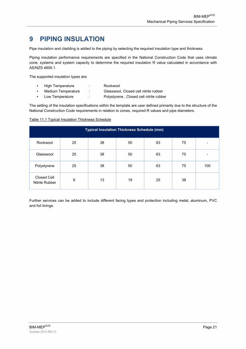
9 PIPING INSULATION
Pipe insulation and cladding is added to the piping by selecting the required insulation type and thickness.
Piping insulation performance requirements are specified in the National Construction Code that uses climate
zone, systems and system capacity to determine the required insulation R value calculated in accordance with
AS/NZS 4859.1.
The supported insulation types are:
• High Temperature : Rockwool
• Medium Temperature : Glasswool, Closed cell nitrile rubber
• Low Temperature : Polystyrene , Closed cell nitrile rubber
The setting of the insulation specifications within the template are user defined primarily due to the structure of the
National Construction Code requirements in relation to zones, required R values and pipe diameters.
Table 11.1 Typical Insulation Thickness Schedule
Typical Insulation Thickness Schedule (mm)
Rockwool 25 38 50 63 75 �
Glasswool 25 38 50 63 75 �
Polystyrene 25 38 50 63 75 100
Closed Cell
Nitrile Rubber 9 13 19 25 38
Further services can be added to include different facing types and protection including metal, aluminum, PVC
and foil linings.

BIM�MEPAUS
Mechanical Piping Services Specification
BIM�MEPAUS
Page 22 October 2014 REV 0
ANNEXURE A INDUSTRY PRACTICE REVIEW
Given the large number of standards related to piping and insulation and the relatively small size of the Australian
market, the industry has rationalized products and methods used to complete HVAC piping installations.
The following provides an overview of industry practice and background information to the development of the
services provided within the BIM�MEPAUS
template.
A1.1 Pipe and Tube
The differences between pipe and tube are in part related to their purpose and part by their fabrication.
Pipe standards use internal nominal dimensions as their primary purpose is related to the transfer of fluids and
gases – pipe standards generally use DN to nominate size and schedules to specify pipe wall thickness.
Tube standards use external dimensions as they are often used for structural fabrication – they use exact external
diameters and exact wall thickness.
Carbon steel and stainless steel generally uses piping standards whilst copper and fabricated stainless steel
including spiral welded stainless steel use tube standards.
BIM�MEPAUS
uses nominal diameter for all pipes and tubes but includes the pipe OD and wall thickness within its
parameters.
A1.2 Copper Tube and Fittings
Copper tube is widely used in HVAC piping due to its comparative cost advantages, ease of handling as well as
corrosion resistance; however its use is limited by its available pressure rating which is temperature dependent
within the typical HVAC operating temperature ranges.
Australian copper tube up to DN 200 complies with AS 1432 and is suitable for a wide range of joining methods
including flanging, press�fit, crimp, compression, capillary and brazed joints. The majority of copper tube is Type
B, however where higher design pressure ratings are required Type A tube can be utilised to gain some additional
working pressure rating.
There are no dimensional standards in relation to Australian copper fittings however in most instances this is not
critical provided that centre line to centre line dimensions are used for fabrication.
For applications above DN200, copper tube and fittings can be fabricated to order from specialist suppliers �
temperature and pressure ratings must be supplied by the manufacturer in all cases.
Valves and other in�line components for copper tube are generally threaded up to and including DN 50 and are
typically flanged above DN 50 typically AS 2129 Table E or ISO 7005�1 PN16 or PN25 to match European
sourced line components.
It is noted that New Zealand uses an alternate copper pipe and fitting standard NZS 3501 Copper Tubes for
water, gas and sanitation that is incompatible with AS 1432 tube.
Refrigerant and Medical Gas copper piping is generally specified to AS 1571 and is cleaned and sealed to
minimise the risk of contamination.

BIM�MEPAUS
Mechanical Piping Services Specification
BIM�MEPAUS
Page 23 October 2014 REV 0
A1.3 Carbon Steel Pipe and Fittings
Carbon Steel pipework is widely used within HVAC piping applications for larger pipe sizes due to either lower
installed cost or its pressure rating. The use of steel however can extend down to DN 32 particularly where floor
take�offs are required for high rise applications.
The following points have been considered in the development of the BIM�MEPAUS
carbon steel piping service:
• Pipe wall thicknesses, dimensions and weights are specified using ASME B36.10. Pipe for Australian
HVAC applications is generally supplied as ASME B36.10 STD Weight – this is equivalent to Schedule
40 up to and including DN 250. (Schedule 40 pipe DN 300 and above is typically a special import).
• ASTM A106 is used to specify the steel quality and strength for high temperature applications.
• ERW pipe is predominately used in Australia and is the most cost effective carbon steel pipe suitable for
the majority of HVAC applications. ERW carbon steel pipe material and strength properties are generally
specified and supplied to comply with API 5L Grade B STD WT. The ERW seam weld introduces a de�
rating factor of 0.85 when compared with seamless pipe that in most applications does not impose a
constraint on its application.
• Seamless pipe to ASTM A106 is generally specified for high temperature applications or where weld
testing and certification is specified due to its improved dimensional tolerances. This seamless carbon
steel line pipe concurrently complies with APL 5L Grade B.
• Carbon Steel Butt Weld fittings are manufactured from seamless pipe to ASTM A106 and compliance
with ASME B16.9 STD WT and ASME B36.10.
A1.4 Stainless Steel Pipe, Tube and Fittings
Stainless steel pipework is normally a special application pipework used where higher corrosion resistance is
required. – The following points are noted in relation to use of the Stainless Steel Services:
• Stainless steel seamless and ERW pipe is specified to ASTM A312 whilst stainless steel spiral tube is
specified to ASTM A778.
• Condenser water systems are generally specified as ASTM A312 TP 316L and/or ASTM A778 TP 316L.
TP 304L is typically used for boiler flue applications due to its suitability for higher operating
temperatures.
• Stainless Steel designated L indicates Low Carbon stainless steel with most project specifications now
requiring the use of low carbon stainless steel.
• Stainless steel pipework are typically supplied as Schedule 10 pipe up to and including DN100, however
some suppliers can supply stainless steel pipe up to DN150. For higher pressure applications it is also
possible to source Schedule 40 pipe in similar size ranges.
• Stainless steel services DN125 and above are typically supplied as 1.6mm spiral welded tube, with
2.0mm and 3.0mm wall thicknesses also available where higher pressure ratings or stiffness are
required. For pressure ratings of stainless steel tube reference should be made to the specific
manufacturer’s pressure rating data.
• For dimensional data related to spiral welded tube reference should be made to the manufacturer’s
technical data as there are no published standards for these components.
• Stainless Steel pipework is normally procured fully prefabricated and passivated from specialist
manufacturers due to the quality advantages that can be achieved with machine welding in a controlled
environment.

BIM�MEPAUS
Mechanical Piping Services Specification
BIM�MEPAUS
Page 24 October 2014 REV 0
• Whilst stainless steel has a high pressure rating it is noted that it is prone to collapse under negative
pressure due to its thin wall construction. Special care is required in system design to minimise this risk.
• Copper content in stainless steel systems should be minimised as far as possible as copper ions in
solution can cause pitting of stainless steel pipe – in particular along the welded joints.
A1.5 Jointing Methods
In recent times a number of new pipe jointing methods have dramatically changed pipework installation practices.
There are now five principal jointing methods used across various HVAC piping services:
• Threaded
• Flanged
• Brazed
• Crimped
• Roll Grooved
• Welded.
The following practices are noted in relation to these joining methods:
A1.5.1 Welded Connections
• Pipework welding is generally now limited to headers, floor take�offs for heating, chilled water and
condenser water systems or where roll�grooved fittings cannot be used due to spatial limitations. In
addition, pipework for high temperature/high pressure heating water systems tends to be fully welded
and flanged.
• There is a significant difference in welding standards for mechanical and fire protection services – all mechanical services pipe welding should be full penetration welding to AS 4041 to assure weld strength and minimise the risk of joint corrosion.
A1.5.2 Flanged Connections
Carbon Steel
• The majority of flanges are supplied as slip on flanges � these fit over the pipe and are welded into place
on the pipe; three flange tables are generally used AS 2129, ISO and ANSI.
• AS 2129 flanges are supplied as flat slip on flanges: the majority of flanges are Table E providing the
pressure rating of 1400kPA for most applications. Table D is used on some stainless steel pipework
installations where the lower pressure rating of 1000kPA is acceptable.
• ISO PN10, PN16 and PN25 slip on flanges are typically used to connect to in�line and end of line
components supplied with these flanges as standard as well as for higher working pressures when
required. These flanges have raised gasket surfaces and a raised weld ring on the back face.
• ANSI Flanges are generally used for higher temperature and pressure ratings and connection to some
US and international supplied product. Flanges are typically ANSI 150 or 300 and have a similar profile
to the European flanges with a raised gasket face and welding ring on the back face.
BIM�MEPAUS
Mechanical Piping Services Specification
BIM�MEPAUS
Page 25 October 2014 REV 0
Copper
• Copper flanges are normally supplied as slip on flanges with a loose backing ring and incorporate some
form of electrolysis protection required for where copper connects to steel or stainless steel pipe or
fittings.
• These flanges are also typically used for standard flanged joints as well as connection to valves and
fittings.
A1.5.3 Brazed Fittings
• Brazing and soldering are similar techniques used to join copper pipe using capillary actions. Brazing
uses higher temperatures and 5�15% silver brazing rods that provide a higher working pressure
generally to match the AS1432 safe working pressure.
A1.5.4 Crimping Fittings
• Mechanical compression fittings such as Viega and B�Press are now widely used on copper pipework up
to DN 50 and have largely replaced on site brazing and soldering of small copper pipework. The use of
crimp fittings offers many benefits over brazed or soldered joints including cleaner pipe systems that
require minimal flushing. A normative standard exists between these fittings in relation in relation to
colour coding, pressure and temperature rating.
• It is important to assure that when using crimp fittings that valves and components can still be removed
without the requirement to cut the pipe by the provision of a union connection.
• Crimp fittings should not be used for de�ionised water.
A1.5.5 Roll Grooved
• Roll groove joining is used for the majority of carbon steel jointing due to its site labour savings. The roll
groove is generally interchangeable but not always and the specific manufacturer couplings should be
used to assure the correct roll groove is provided.
• Roll groove valves and in�line components such as strainers generally offer higher pressure ratings than
Table E flanged components.
• Roll groove joining of copper and stainless steel with the exception of spiral wound tube is also generally
permitted.
A1.5.6 Valves
• Valves are now fully imported into Australia and if not supplied as AS 2127 Table E or roll grooved, then
they will generally be supplied as
o ISO PN16 or PN25 valves for most European sourced components
o ANSI 150 / ANSI 300 for most higher pressure rated valves.
Table H flanged valves and fittings are a special order and should generally not be specified if possible.

BIM�MEPAUS
Mechanical Piping Services Specification
BIM�MEPAUS
Page 26 October 2014 REV 0
ANNEXURE B PIPE HANGER REFERENCE INFORMATION
B1 General Requirements
Resolution of the piping support system is a key engineering responsibility and must address:
• Piping system structural loading;
• Piping system seismic induced structural loading;
• Pipe system expansion, contraction and anchoring; and
• Structure expansion and contraction including vertical building shrinkage.
In addition to the structural loading the hanger design must address:
• Design strength of the hanger rod; and
• Pull out strength of the fixing; determined by the fixing itself and strength of the concrete or steel framing
fixing point.
Specification development for the pipe support and hangers is an engineering design function and the layout
should be completed through the virtual build process to a documented specification.
Piping support spacings are typically specified to comply with AS 4041 and AS 3500 � these are generally
determined by pipe sag and induced pipe stress considerations. They do not address the structural design of the
support or fixing and these generally lead to much closer spacings of the hangers and supports being required,
particularly in the larger pipe sizes.
Set�up of the Revit MEP pipe hanger service is not part of the BIM�MEPAUS
template and remains the
responsibility of the user.
B2 Pipe Support Design Methodology
Pipe hanger spacings used in practice are typically closer than those provided in the relevant Australian
Standards due to the excessive structural loadings that tend to occur with these spacings.
The following provides overview of the engineering principles that are used to define piping hanger service:
Load Determination
The determination of the pipe weight is a function of the pipe and fluid content; reference tables are
available providing nominal mass/m data for AS 1432 Copper tubes and APL 5L carbon steel pipes and
ASTM A312 stainless steel pipes.
Rod Size Determination
The size of the rod used will be determined by the load, the rod strength and the hanger type. A safety
factor of 5 is commonly applied to hanger rod yield strength to determine its design load carrying
capacity.
Rod Sizes are typically selected between M10 to M24.
Fixing Determination
There are a number of fixing types available with fixings typically rated for pull out strength for a specified
concrete strength and/or fixing arrangement. The proposed fixing type should be checked with the
structural engineer and the supplier prior to finalizing the fixing selection.
In many instances a pull out strength test will be required when large pipework is to be hung to verify the
capacity of the structure and fixing combination.
END.