billy goat pl2500sph
DESCRIPTION
englishTRANSCRIPT

PL25SPH Owner’s Manual
Part No 100383 1 Form No F072215C
AERATOR Owner's Manual
PL2500SPH U.S. PATENT #6892821
Replacement Parts
TINE REPLACEMENT
Replacement tip for aerating tines.
P/N 381057
TINE BUSHING REPLACEMENTS
Replacement bushings for the tines
P/N 380213
PL25SPH Owner’s Manual
Part No 100383 Form No F072215C
2
CONTENTS
SPECIFICATIONS 3 INTENDED USE 4 INSTRUCTION LABELS 5 PACKING CHECKLIST & ASSEMBLY 6 OPERATION 7 MAINTENANCE 8 TROUBLE SHOOTING AND WARRANTY 9 ILLUSTRATED PARTS & PARTS LIST 10-11

PL25SPH Owner’s Manual
Part No 100383 Form No F072215C
3
SPECIFICATIONS
PL2500SPH
Engine: cc 196cc
Engine: Honda GX200 w/Gearbox
Engine: Fuel Capacity 3.3 qt. (3.1 L)
Engine: Oil Capacity 0.63 qt. (0.58 L)
Total Unit Weight: 360# (163.3 Kg)
Length 67.5” (1.7m)
Width 32.5” (.83m)
Height 41.25” (1m)
Max. operating slope 15o
Sound test in accordance with 2000/14/EC
106
Sound at operators ear
86
Vibration at operator position
.61g (6.00m/s2)
SOUND
SOUND LEVEL 82 dB(a) at Operators Position
Sound tests were conducted in accordance with 2000/14/EC, and were performed on 9/26/14 under the conditions listed below.
Sound power level listed is the highest value for any model covered in this manual. Please refer to serial plate on the unit for the sound power level for your model.
General Conditions: Sunny Temperature: 66
oF (18.9
oC)
Wind Speed: 8 mph (12.8 kph) Wind Direction: South Humidity: 78% Barometric Pressure: 30 Hg (101.59 kpa)
VIBRATION DATA
VIBRATION LEVEL .61g (6.00 m/s
2)
Vibration levels at the operator’s handles were measured in the vertical, lateral and longitudinal directions using calibrated vibration test equipment. Tests were performed on 9/25/14 under the conditions listed below. General Conditions: Sunny Temperature: 79
oF (26
oC)
Wind Speed: 13 mph (21 kph) Wind Direction: South Humidity: 47% Barometric Pressure: 30Hg (101.6 kpa)
106
PL25SPH Owner’s Manual
Part No 100383 Form No F072215C
4
INTENDED USE AERATOR
This machine is designed for aerating established lawns and large grass covered areas. The machine should not be used for any other purpose than that stated above.
DO NOT OPERATE IF EXCESSIVE VIBRATION OCCURS! If excessive vibration occurs, shut engine
off immediately and check for damaged or worn reel, loose reel bearing, loose engine or lodged debris. To remove debris from the machine, see the machine specific trouble shooting section. Note: See parts list for proper bolt torque specifications.
HANDLING & TRANSPORTING
Always use two or more people to lift these machines. Lift holding on either side of the machine, using the handles and the frame. Secure in place during transportation. See specifications for unit weight. For safety use gloves when lifting.
Never lift any machine while the engine is running.
PL25SPH Owner’s Manual
Part No 100383 Form No F072215C
5
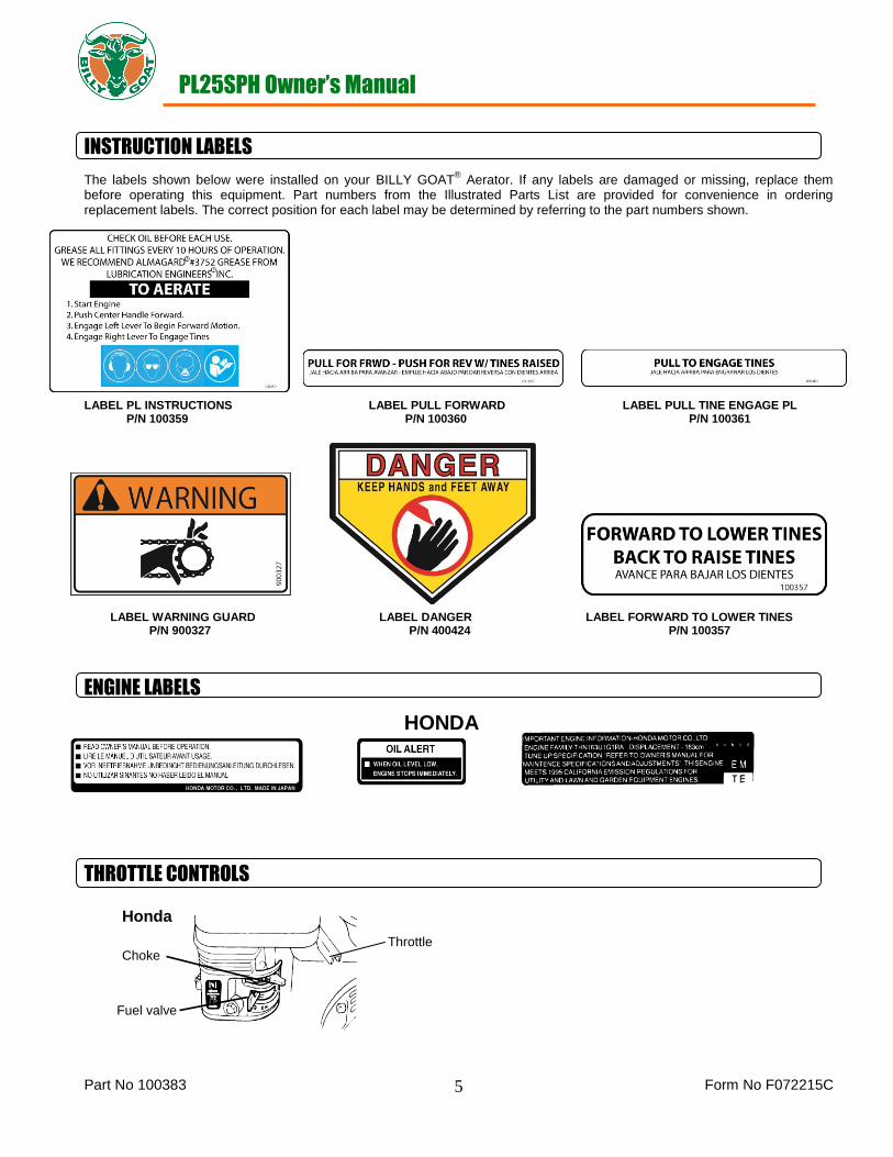
INSTRUCTION LABELS
The labels shown below were installed on your BILLY GOAT® Aerator. If any labels are damaged or missing, replace them
before operating this equipment. Part numbers from the Illustrated Parts List are provided for convenience in ordering replacement labels. The correct position for each label may be determined by referring to the part numbers shown.
LABEL PL INSTRUCTIONS LABEL PULL FORWARD LABEL PULL TINE ENGAGE PL P/N 100359 P/N 100360 P/N 100361
LABEL WARNING GUARD LABEL DANGER LABEL FORWARD TO LOWER TINES P/N 900327 P/N 400424 P/N 100357
ENGINE LABELS
THROTTLE CONTROLS
HONDA
Honda
Fuel valve
Throttle Choke

PL25SPH Owner’s Manual
Part No 100383 Form No F072215C
6
PACKING CHECKLIST Your Billy Goat is shipped from the factory in one carton with the handle and cables detached.
PUT OIL IN ENGINE BEFORE STARTING
ASSEMBLY
READ all safety instructions before assembling unit. TAKE CAUTION when removing the unit from the box.
69
NOTE: Items in ( ) can be referenced in the Parts Illustration and Parts List on pages 10-11.
1. REMOVE the two bolts and nuts from the hardware bag (item 44 and 5).
2. ATTACH the upper handle (item 70) by sliding it into the rear facing holes and attaching it with the hardware from step 1.
NOTE: The bail should be facing downward.
3. ATTACH the tine lift cable (item 49) to the tine lever (item 69) in the center of the handle by inserting the pin (item 88) into it in the hole closest to the end of the handle and then inserting the rue ring (item 6). See Fig. 1 below and reference Part
Illustration on page 10.
4. ATTACH the drive cable (item 78) to the left side bracket on the handle (item 70) by sandwiching the two nuts on the
bracket and tightening. Install cable adjuster (item 71) by threading it on the end of the cable until thread begins to show. NOTE: Protruding portion of the threaded adjuster must be facing the operator when installed. Check to make sure
the cables are functioning properly before operation and not binding. If adjustments are needed for belt tension on the bail cable, loosen the nuts and move the sandwiching position up or down for the desired tension.
NOTE: if the tension is too loose the tines will not engage and if it is too tight premature wear could happen to the belt.
5. ATTACH the tine cable (item 77) to the right side bracket on the handle (item 70) using the same method previously used
for the drive cable. Check for proper operation and adjust the tension accordingly.
6. CHECK engine oil level and fill to proper level. Also check oil in gear reduction reservoir and fill if necessary. See engine
owner’s manual for type and amount of oil to use. Move the tine engagement lever to the down position, to level engine during checking.
7. SET the engine stop switch, located on the upper handle, to the ON position.
Boxing Parts Checklist
Owner’s Manual 100383 Engine Manual Per Model
Honda
PARTS BAG & LITERATURE ASSY
Warranty card P/N- 400972, Owner’s Manual P/N-100383, Declaration of Conformity P/N-381503, General Safety and Warranty Manual Renovation P/N-100295
Attach (item 49) cable here
Fig. 1 handle

PL25SPH Owner’s Manual
Part No 100383 Form No F072215C
7
OPERATION
STARTING ENGINE
See engine manufacturer’s instructions for type and amount of oil and gasoline used. Engine must be level when checking and filling oil and gasoline.
ON/OFF SWITCH: Set the On/Off Switch to the On position.
ENGINE SPEED: Controlled by lever on the engine. Under normal conditions, operate at the minimum throttle speed to accomplish your task. FUEL VALVE: Move fuel valve to "ON" position. (Honda: Located below the air cleaner on the engine.)
CHOKE: Engage the choke when starting a cold engine. (Honda: Located below the air cleaner on the engine.)
THROTTLE: Move the throttle control lever on the engine to fast position. Pull starting rope to start engine
IF YOUR UNIT FAILS TO START: check trouble shooting section in operator’s manual. Also see engine manual. Honda engines are equipped with a low oil sensor to prevent engine damage. When it senses a low oil condition (i.e. unit is
operating or sitting on a steep slope) the engine shuts down. The low oil condition must be corrected before the engine can be restarted. See the engine owner’s manual for more information.
AERATING OPERATION
NOTE: NEVER PARK THIS UNIT ON A SLOPE OF ANY KIND. Always keep tines in the up position when parking the unit.
TINES RAISING/LOWERING: The tines are raised or lowered into the ground by operating the tine engagement lever on the upper handle. Tine penetration is very dependent on surface preparation. READ the entire operation section before aerating. ENGAGING DRIVE: Pull up on the left lever only. Likewise, for reverse push the lever down (only use reverse with the tines up).
ENGAGE TINES: With the aerator in the work area, lower the tines by releasing the center lever on the handle. When the lever is in the forward position, pull up on the tine engage bail (left hand) to engage the tines. AERATE: Engage the drive bail (right hand) for forward momentum while engaging the tine bail (left hand). NOTE: in cold temperatures engage the tines in the up position for two minutes to warm the cam grease. For maximum tine penetration apply downward pressure on the handle.
TURNING: At the end of an aerating run, release the drive and tine bails and raise the tines out of the ground. Then reposition the unit for another pass and lower the tines to begin another run.
TRANSPORT: Be sure to raise tines out of the ground (disengaging the bail and then raising the tines with the center lever) before transporting away from the work area. *****TIPS*****
MOW
Mow the lawn to its normal cut height.
WATER
For the best performance and maximum tine penetration the lawn should be thoroughly watered the day before aeration.
INSPECT
Check the lawn before beginning work. Remove all rocks, wire, string, or other objects that can present a hazard during work prior to starting.
IDENTIFY
Mark all fixed objects to be avoided during work, such as sprinkler heads, water valves, buried cables, or clothes line anchors, etc.
SLOPES
Do not operate the aerator on steep slopes (exceeding 15o). Use extreme caution when operating on any sloped surface. For
lesser sloped areas operate the unit, traversing up and down at a 45 degree angle to the slope rather than straight across. Extended operation on steep slopes can cause engine damage. NOTE: Honda engines are equipped with a low oil sensor to prevent engine damage. When it senses a low oil condition (i.e. unit is operating or sitting on a steep slope) the engine shuts down. The low oil condition must be corrected before the engine can be restarted. See the engine owner’s manual for more information.

PL25SPH Owner’s Manual
Part No 100383 Form No F072215C
8
MAINTENANCE
NOTE: Items in ( ) can be referenced in the Parts Illustration and Parts List on pages 10-11.
PERIODIC MAINTENANCE
Periodic maintenance should be performed at the following intervals:
Maintenance Operation Every Use (daily) Every 10 hrs Every 50 Hrs Every 100 Hrs
Inspect for loose, worn or damaged parts
Check engine oil
Inspect belt for wear
Engine (See engine manual)
Grease Cam bearings (recommend using Almagard #3752)
Thoroughly clean all debris from unit and tines
Replace tine bushings
Grease shaft bearings and wheel bearings
ENGINE MUST BE LEVEL WHEN CHECKING OR FILLING OIL
INDIVIDUAL TINE REPLACEMENT
1. Wait for engine to cool and disconnect spark plug.
2. Loosen the jam nut (item 12) then unscrew the tine (item 13).
3. Replace the tine making sure to use the maximum amount of threads on the tine. NOTE: Tines are a normal wear item and should be inspected regularly for signs of wear or damage.
ADJUSTING BELT TENSION-
1. Adjust the clutch cable (item 78) by threading the cable adjuster (item 52) further onto the cable to tighten belt. The opposite direction will loosen the belt. Do not over tighten the v-belt. This puts a load on the engine gearbox bearings. The belt is tight enough when it does not slip during operation.
2. Also loosen engine and slide in slots to apply or relieve tension on belt. NOTE: A worn belt will not allow for proper adjustment and must be replaced.
TINE BELT REPLACEMENT
1. Disconnect the spark plug.
2. Remove the lower and upper tensioner brackets (items 63 and 64) on both sides of the pulley (item 81).
3. Walk the belts (item 89) off of the engine pulley.
4. Attach a hoist mechanism to the cam shaft (item 51), and then remove the four bolts, washers, and nuts (items 85, 8 and 9) that attach the bearing (item 7) of the cam shaft to the frame.
5. Raise the cam shaft out of the frame and remove the old belt.
6. To replace the belt, simply slide the new belt onto the pulley when the cam shaft is raised then follow the previous steps in reverse to install.
DRIVE BELT REPLACEMENT
1. Disconnect the spark plug.
2. Follow Steps 1-5 in the tine belt replacement section above. The tine belt will need to be removed before the Drive belt can be removed.
3. Remove the idler (item 47) and hardware (items 8, 9, and 25).
4. Loosen the tension bolt (item 99) so that the idler pulley (item 3) releases tension on the drive belt (item 79)
5. Walk the drive belt off of the pulleys and remove the old belt.
6. To replace the belt put the drive belt on in reverse order. (make sure not to over-tighten the tension bolt as this could lead to premature failure of the belt.
7. After the new drive belt is on then attach the tine belt in reverse order from the steps that it was removed.

PL25SPH Owner’s Manual
Part No 100383 Form No F072215C
9
TROUBLESHOOTING
WARRANTY INFORMATION When servicing engine refer to specific manufacturer’s engine owner's manual. Engine warranty is covered by the specific engine manufacturer. If your engine requires warranty or other repair work contact your local servicing engine dealer. When contacting a dealer for service it is a good idea to have your engine model number available for reference (See table page 3). If you cannot locate a servicing dealer in your area you can contact the manufacturer’s national service organization. To reach:
American Honda: 800-426-7701 Briggs and Stratton: 414-479-8008 WARRANTY CLAIM PROCEDURE
Should a BILLY GOAT® machine fail due to a defect in material and/or workmanship, the owner should make a warranty claim
as follows:
The machine must be taken to the dealer from whom it was purchased or to an authorized Servicing BILLY GOAT Dealer.
The owner must present the remaining half of the Warranty Registration Card, or, if this is not available, the invoice or receipt.
The Warranty Claim will be completed by the authorized BILLY GOAT Dealer and submitted to their respective BILLY GOAT Distributor for their territory Attention: Service Manager. Any parts replaced under warranty must be tagged and retained for 90 days. The model number and serial number of the unit must be stated in the Warranty Claim.
The distributor service manager will sign off on the claim and submit it to BILLY GOAT for consideration.
The Technical Service Department at BILLY GOAT will study the claim and may request parts to be returned for examination. BILLY GOAT will notify their conclusions to the distributor service manager from whom the claim was received.
The decision by the Technical Service Department at BILLY GOAT to approve or reject a Warranty Claim is final and binding.
For online product registration go to www.billygoat.com
Problem Possible Cause Solution
Engine will not start Stop switch off. Throttle in off position.
Engine not in full choke position. Out of
gasoline. Bad or old gasoline. Spark plug
wire disconnected. Dirty air cleaner. Engine
oil level too low (Honda only).
Check stop switches, throttle, choke
position and gasoline. Connect spark
plug wire. Clean or replace air cleaner.
Or contact a qualified service person.
Check and fill engine oil.
Abnormal vibration Damaged or missing tines. Loose handle
bolts. Loose engine bolts.
Stop work immediately. Replace any
damaged or missing tines. Tighten all
loose bolts and nuts.
Engine stalls or labors
when aerating
Working on too steep of a slope. Not enough
oil in the engine.
Work at 45 degrees to the slope moving
up and down instead of across. Check
and add engine oil.
Engine is locked, will not
pull over
Debris locked against reel, or drive pulleys.
Engine problem.
Pull spark plug wire and remove debris.
Contact an engine servicing dealer for
engine problems.
Unit does not move when
clutch is engaged.
Belt drive out of adjustment. Worn drive belt.
Loose or damaged pulleys. Damaged or
broken clutch cable.
See maintenance on pg. 10 of this
manual. Contact a qualified servicing
dealer.

PL25SPH Owner’s Manual
Part No 100383 Form No F072215C
10
PL2500SPH PARTS DRAWING
PL25SPH Owner’s Manual
Part No 100383 Form No F072215C
11
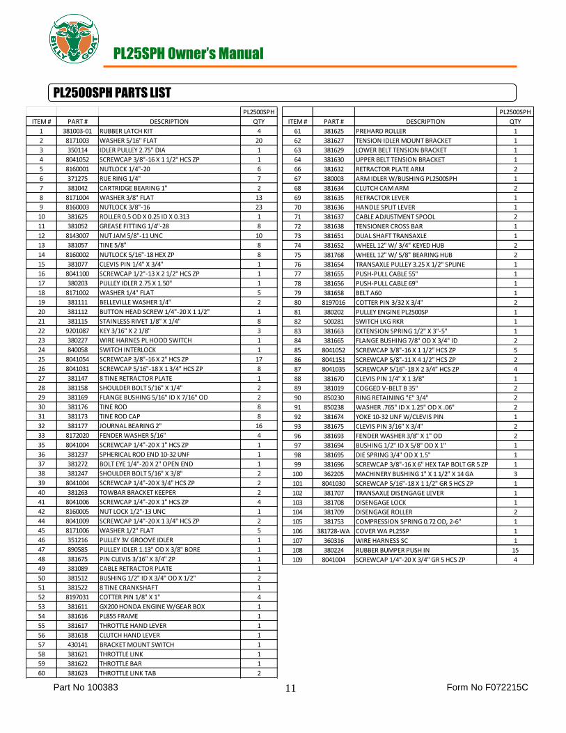
PL2500SPH PARTS LIST
PL2500SPH
ITEM # PART # DESCRIPTION QTY
61 381625 PREHARD ROLLER 1
62 381627 TENSION IDLER MOUNT BRACKET 1
63 381629 LOWER BELT TENSION BRACKET 1
64 381630 UPPER BELT TENSION BRACKET 1
66 381632 RETRACTOR PLATE ARM 2
67 380003 ARM IDLER W/BUSHING PL2500SPH 1
68 381634 CLUTCH CAM ARM 2
69 381635 RETRACTOR LEVER 1
70 381636 HANDLE SPLIT LEVER 1
71 381637 CABLE ADJUSTMENT SPOOL 2
72 381638 TENSIONER CROSS BAR 1
73 381651 DUAL SHAFT TRANSAXLE 1
74 381652 WHEEL 12" W/ 3/4" KEYED HUB 2
75 381768 WHEEL 12" W/ 5/8" BEARING HUB 2
76 381654 TRANSAXLE PULLEY 3.25 X 1/2" SPLINE 1
77 381655 PUSH-PULL CABLE 55" 1
78 381656 PUSH-PULL CABLE 69" 1
79 381658 BELT A60 1
80 8197016 COTTER PIN 3/32 X 3/4" 2
81 380202 PULLEY ENGINE PL2500SP 1
82 500281 SWITCH LKG RKR 1
83 381663 EXTENSION SPRING 1/2" X 3"-5" 1
84 381665 FLANGE BUSHING 7/8" OD X 3/4" ID 2
85 8041052 SCREWCAP 3/8"-16 X 1 1/2" HCS ZP 5
86 8041151 SCREWCAP 5/8"-11 X 4 1/2" HCS ZP 2
87 8041035 SCREWCAP 5/16"-18 X 2 3/4" HCS ZP 4
88 381670 CLEVIS PIN 1/4" X 1 3/8" 1
89 381019 COGGED V-BELT B 35" 2
90 850230 RING RETAINING "E" 3/4" 2
91 850238 WASHER .765" ID X 1.25" OD X .06" 2
92 381674 YOKE 10-32 UNF W/CLEVIS PIN 1
93 381675 CLEVIS PIN 3/16" X 3/4" 2
96 381693 FENDER WASHER 3/8" X 1" OD 2
97 381694 BUSHING 1/2" ID X 5/8" OD X 1" 1
98 381695 DIE SPRING 3/4" OD X 1.5" 1
99 381696 SCREWCAP 3/8"-16 X 6" HEX TAP BOLT GR 5 ZP 1
100 362205 MACHINERY BUSHING 1" X 1 1/2" X 14 GA 3
101 8041030 SCREWCAP 5/16"-18 X 1 1/2" GR 5 HCS ZP 1
102 381707 TRANSAXLE DISENGAGE LEVER 1
103 381708 DISENGAGE LOCK 1
104 381709 DISENGAGE ROLLER 2
105 381753 COMPRESSION SPRING 0.72 OD, 2-6" 1
106 381728-WA COVER WA PL25SP 1
107 360316 WIRE HARNESS SC 1
108 380224 RUBBER BUMPER PUSH IN 15
109 8041004 SCREWCAP 1/4"-20 X 3/4" GR 5 HCS ZP 4
PL2500SPH
ITEM # PART # DESCRIPTION QTY
1 381003-01 RUBBER LATCH KIT 4
2 8171003 WASHER 5/16" FLAT 20
3 350114 IDLER PULLEY 2.75" DIA 1
4 8041052 SCREWCAP 3/8"-16 X 1 1/2" HCS ZP 1
5 8160001 NUTLOCK 1/4"-20 6
6 371275 RUE RING 1/4" 7
7 381042 CARTRIDGE BEARING 1" 2
8 8171004 WASHER 3/8" FLAT 13
9 8160003 NUTLOCK 3/8"-16 23
10 381625 ROLLER 0.5 OD X 0.25 ID X 0.313 1
11 381052 GREASE FITTING 1/4"-28 8
12 8143007 NUT JAM 5/8"-11 UNC 10
13 381057 TINE 5/8" 8
14 8160002 NUTLOCK 5/16"-18 HEX ZP 8
15 381077 CLEVIS PIN 1/4" X 3/4" 1
16 8041100 SCREWCAP 1/2"-13 X 2 1/2" HCS ZP 1
17 380203 PULLEY IDLER 2.75 X 1.50" 1
18 8171002 WASHER 1/4" FLAT 5
19 381111 BELLEVILLE WASHER 1/4" 2
20 381112 BUTTON HEAD SCREW 1/4"-20 X 1 1/2" 1
21 381115 STAINLESS RIVET 1/8" X 1/4" 8
22 9201087 KEY 3/16" X 2 1/8" 3
23 380227 WIRE HARNES PL HOOD SWITCH 1
24 840058 SWITCH INTERLOCK 1
25 8041054 SCREWCAP 3/8"-16 X 2" HCS ZP 17
26 8041031 SCREWCAP 5/16"-18 X 1 3/4" HCS ZP 8
27 381147 8 TINE RETRACTOR PLATE 1
28 381158 SHOULDER BOLT 5/16" X 1/4" 2
29 381169 FLANGE BUSHING 5/16" ID X 7/16" OD 2
30 381176 TINE ROD 8
31 381173 TINE ROD CAP 8
32 381177 JOURNAL BEARING 2" 16
33 8172020 FENDER WASHER 5/16" 4
35 8041004 SCREWCAP 1/4"-20 X 1" HCS ZP 1
36 381237 SPHERICAL ROD END 10-32 UNF 1
37 381272 BOLT EYE 1/4"-20 X 2" OPEN END 1
38 381247 SHOULDER BOLT 5/16" X 3/8" 2
39 8041004 SCREWCAP 1/4"-20 X 3/4" HCS ZP 2
40 381263 TOWBAR BRACKET KEEPER 2
41 8041006 SCREWCAP 1/4"-20 X 1" HCS ZP 4
42 8160005 NUT LOCK 1/2"-13 UNC 1
44 8041009 SCREWCAP 1/4"-20 X 1 3/4" HCS ZP 2
45 8171006 WASHER 1/2" FLAT 5
46 351216 PULLEY 3V GROOVE IDLER 1
47 890585 PULLEY IDLER 1.13" OD X 3/8" BORE 1
48 381675 PIN CLEVIS 3/16" X 3/4" ZP 1
49 381089 CABLE RETRACTOR PLATE 1
50 381512 BUSHING 1/2" ID X 3/4" OD X 1/2" 2
51 381522 8 TINE CRANKSHAFT 1
52 8197031 COTTER PIN 1/8" X 1" 4
53 381611 GX200 HONDA ENGINE W/GEAR BOX 1
54 381616 PL855 FRAME 1
55 381617 THROTTLE HAND LEVER 1
56 381618 CLUTCH HAND LEVER 1
57 430141 BRACKET MOUNT SWITCH 1
58 381621 THROTTLE LINK 1
59 381622 THROTTLE BAR 1
60 381623 THROTTLE LINK TAB 2