bhr surgical technique - us - smith & nephew bene the technique description herein is made...
TRANSCRIPT
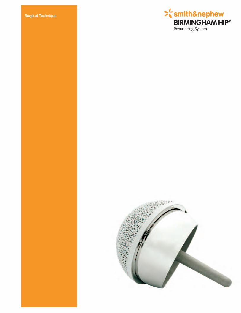
Surgical Technique
The requirements of a surgical approach to the hip for arthroplasty arefirstly an adequate exposure allowing good visualization and optimumcomponent insertion, and secondly the minimum of damage to theneuromuscular structures around the hip.
In conventional stemmed total hip replacement it is resection of thefemoral head that affords easy visualization of the acetabulum withmany surgical approaches to the hip. With resurfacing, this additionalhelp in the surgical exposure is clearly not an option.
In an elderly, inactive patient undergoing THR, a degree ofneuromuscular damage, inevitable in certain surgical approaches,seems compatible, at least in some cases with reasonable functionaloutcome. In a younger active patient undergoing hip resurfacinghowever, such neuromuscular damage produces an unacceptablelimited functional outcome.
Over the past 10 years I have tried most surgical approaches for hipresurfacing. For reasons of good exposure, rapid rehabilitation andnormal hip function, the posterior approach is strongly recommended.Trochanteric osteotomy gives a splendid extensile exposure and may beuseful if a hip ankylosis is to be tackled. The osteotomised fragmentshould be small, and great care needs to be paid to trochanteric re-attachment and patient rehabilitation if trochanteric escape and non-union is to be avoided.
It is not reasonable to select a highly sophisticated device like theBIRMINGHAM HIP™ Resurfacing (BHR™) System and then damage theabductor muscles or their nerve supply in the surgical approach, useforcible retraction causing muscle tearing and heterotopic ossification,malposition the components due to poor visualization, and still expect agood result.
In a personal experience of over 2000 hip resurfacings it has been verygratifying to see patients recover excellent function after this procedureand lead a normal lifestyle, including participation in recreational andcompetitive sport.
No operative technique manual can be entirely comprehensive, but thesteps included in this brochure are considered to be the essentialelements in adopting this surgical procedure.
Derek McMinn FRCSConsultant Orthopaedic Surgeon
Introduction
Nota Bene
The technique description herein is made available to the healthcare professional toillustrate the suggested treatment for the uncomplicated procedure. In the final analysis,the preferred treatment is that which addresses the needs of the specific patient.
BIRMINGHAM HIP™Resurfacing System
Contents
Indications/Contraindications ..............................................................4
Warnings and Precautions ....................................................................5
Surgical Approach ................................................................................5
Pre-Operative Planning ........................................................................6
Acetabular Preparation ........................................................................7
Curved Cup Introducer..........................................................................10
Acetabular Cup Wiring Instruction........................................................11
Femoral Preparation ..............................................................................14
Using the McMinn Alignment Jig..........................................................15
Short Arm Alignment Jig Technique ....................................................17
Using the Sleeve Cutter Stop................................................................21
Using the Stem Drill ..............................................................................30
Dysplasia Cup ......................................................................................34
Thrombo-embolic Prophylaxis ..............................................................38
Acetabular Cup Extraction Kit ..............................................................40
Catalogue Information ..........................................................................42
Important Medical Information..............................................................44
Indications for use
The BIRMINGHAM HIP™ Resurfacing System (BHR™) is a single usedevice intended for hybrid fixation: cemented femoral headcomponent and cementless acetabular component.
The BHR system is intended for use in patients requiring primary hipresurfacing arthroplasty due to:
• Non-inflammatory arthritis (degenerative joint disease) such asosteoarthritis, traumatic arthritis, avascular necrosis, ordysplasia/DDH, or
• Inflammatory arthritis such as rheumatoid arthritis.
The BHR system is intended for patients who, due to their relativelyyounger age or increased activity level, may not be suitable fortraditional total hip arthroplasty due to an increased possibility ofrequiring future ipsilateral hip joint revision.
• Patients with infection or sepsis
• Patients who are skeletally immature
• Patients with any vascular insufficiency, muscular atrophy, orneuromuscular disease severe enough to compromise implantstability or postoperative recovery
• Patients with bone stock inadequate to support the device including:
- Patients with severe osteopenia or with a family history of severeosteoporosis or severe osteopenia
- Patients with osteonecrosis or avascular necrosis (AVN) with >30%involvement of the femoral head (regardless of FICAT Grade)
- Patients with multiple cysts of the femoral head (>1cm)
- Note: In cases of questionable bone stock, a DEXA scan may benecessary to assess inadequate bone stock
• Females of child-bearing age due to unknown effect on the fetus ofmetal ion release
• Patients with known moderate to severe renal insufficiency
• Patients who are immunosuppressed with diseases such as AIDS orpersons receiving high doses of corticosteroids
• Patients who are severely overweight
• Patients with known or suspected metal sensitivity (e.g., jewelry)
Contraindications
4
Warnings and precautions
• Patients on medications (such as high-dose or chronicaminoglycoside treatment) or with co-morbidities (such as diabetes)that increase the risk of future, significant renal impairment shouldbe advised of the possibility of increase in systemic metal ionconcentration. Preoperative and postoperative monitoring of renalfunction (such creatinine, GFR, BUN) will be necessary.
• Only physicians who have received appropriate training and arefamiliar with the implant components, instruments, procedure,clinical applications, adverse events, and risks associated with theBHR™ system should use this device. Contact Smith & Nephew, Inc.for the surgical technique manual and procedural training protocol.
• Currently, Smith & Nephew, Inc. does not have a commerciallyavailable metal femoral head and stem (monoblock or modular) foruse with a BHR resurfacing cup (one-piece or modular). Therefore, ifthe BHR resurfacing head must be revised to a total hip arthroplasty,the one-piece BHR acetabular cup must also be revised, even if wellfixed; however, in the case of a modular cup, the R3™ AcetabularShell can remain in place if well-fixed, and the R3 Metal Liner mustbe replaced with an R3 Poly Liner, which can be used with anycompatible legally marketed Smith & Nephew femoral stem andmating ceramic or metal femoral head component.
• Based on literature reports1,2 , and the clinical study, the followingwere identified as risk factors for revision: Patients who are female;who receive a smaller component size (≤ 44mm); have the deviceimplanted at a high abduction angle; are obese; or, who have adiagnosis of avascular necrosis have a greater risk of revision thanother patients. The more risk factors a patient has, the greater therisk of procedure failure requiring a revision to the hip.
For additional information on the use of the BHR device, see theInstructions for Use printed at the end of this surgicaltechnique.
The BIRMINGHAM HIP Resurfacing device may be implanted throughvarious hip surgical approaches. The posterior approach, asdescribed by Derek McMinn FRCS is described in this operativetechnique.
Other surgical approaches to the hip may be used however, theposterior approach is favoured by the designer surgeon and hissubmitted clinical data is based on this approach.
The surgical approach
5
Pre-Operative Planning
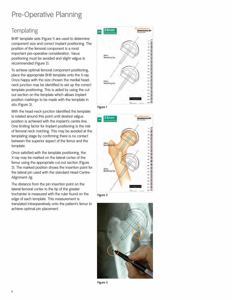
Figure 1
Figure 2
Figure 3
TemplatingBHR™ template sets (Figure 1) are used to determinecomponent size and correct implant positioning. Theposition of the femoral component is a mostimportant pre-operative consideration. Varuspositioning must be avoided and slight valgus isrecommended (Figure 2).
To achieve optimal femoral component positioning,place the appropriate BHR template onto the X-ray.Once happy with the size chosen the medial head-neck junction may be identified to set up the correcttemplate positioning. This is aided by using the cutout section on the template which allows implantposition markings to be made with the template insitu (Figure 3).
With the head-neck-junction identified the templateis rotated around this point until desired valgusposition is achieved with the implant’s centre line.One limiting factor for implant positioning is the riskof femoral neck notching. This may be avoided at thetemplating stage by confirming there is no contactbetween the superior aspect of the femur and thetemplate.
Once satisfied with the template positioning, the X-ray may be marked on the lateral cortex of thefemur using the appropriate cut-out section (Figure3). The marked position shows the insertion point forthe lateral pin used with the standard Head-Centre-Alignment-Jig.
The distance from the pin insertion point on thelateral femoral cortex to the tip of the greatertrochanter is measured with the ruler found on theedge of each template. This measurement istranslated intraoperatively onto the patient’s femur toachieve optimal pin placement.
6
Intra-Operative Templating
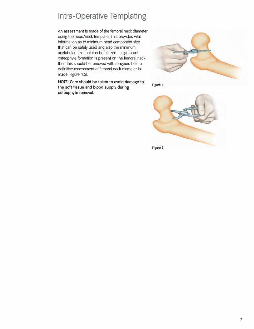
Figure 4
Figure 5
An assessment is made of the femoral neck diameterusing the head/neck template. This provides vitalinformation as to minimum head component size that can be safely used and also the minimumacetabular size that can be utilized. If significantosteophyte formation is present on the femoral neckthen this should be removed with rongeurs beforedefinitive assessment of femoral neck diameter ismade (Figure 4,5).
NOTE: Care should be taken to avoid damage tothe soft tissue and blood supply duringosteophyte removal.
7
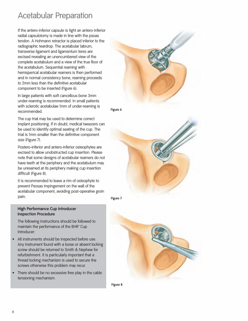
Figure 6
Figure 7
Figure 8
Acetabular Preparation
If the antero-inferior capsule is tight an antero-inferiorradial capsulotomy is made in line with the psoastendon. A Hohmann retractor is placed inferior to theradiographic teardrop. The acetabular labrum,transverse ligament and ligamentum teres areexcised revealing an unencumbered view of thecomplete acetabulum and a view of the true floor ofthe acetabulum. Sequential reaming withhemisperical acetabular reamers is then performedand in normal consistency bone, reaming proceedsto 2mm less than the definitive acetabularcomponent to be inserted (Figure 6).
In large patients with soft cancellous bone 3mmunder-reaming is recommended. In small patientswith sclerotic acetabulae 1mm of under-reaming isrecommended.
The cup trial may be used to determine correctimplant positioning. If in doubt, medical tweezers canbe used to identify optimal seating of the cup. Thetrial is 1mm smaller than the definitive componentsize (Figure 7).
Postero-inferior and antero-inferior osteophytes areexcised to allow unobstructed cup insertion. Pleasenote that some designs of acetabular reamers do nothave teeth at the periphery and the acetabulum maybe unreamed at its periphery making cup insertiondifficult (Figure 8).
It is recommended to leave a rim of osteophyte toprevent Psosas impingement on the wall of theacetabular component, avoiding post-operative groinpain.
High Performance Cup Introducer Inspection Procedure
The following instructions should be followed tomaintain the performance of the BHR™ CupIntroducer:
• All instruments should be inspected before use.Any instrument found with a loose or absent lockingscrew should be returned to Smith & Nephew forrefurbishment. It is particularly important that athread locking mechanism is used to secure thescrews otherwise this problem may recur.
• There should be no excessive free play in the cabletensioning mechanism.
8
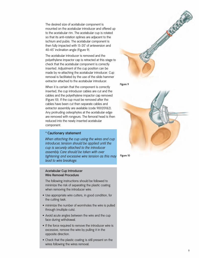
Figure 9
Figure 10
The desired size of acetabular component ismounted on the acetabular introducer and offered upto the acetabular rim. The acetabular cup is rotatedso that its anti-rotation splines are adjacent to theischium and pubis. The acetabular component isthen fully impacted with 15-20˚ of anteversion and40-45˚ inclination angle (Figure 9).
The acetabular introducer is removed and thepolyethylene impactor cap is retracted at this stage tocheck that the acetabular component is correctlyinserted. Adjustment of the cup position can bemade by re-attaching the acetabular introducer. Cupremoval is facilitated by the use of the slide hammerextractor attached to the acetabular introducer.
When it is certain that the component is correctlyinserted, the cup introducer cables are cut and thecables and the polyethylene impactor cap removed(Figure 10). If the cup must be removed after thecables have been cut then separate cables andextractor assembly are available (code 900201&2).Any protruding osteophytes at the acetabular edgeare removed with rongeurs. The femoral head is thenreduced into the newly inserted acetabularcomponent.
Acetabular Cup Introducer Wire Removal Procedure
The following instructions should be followed tominimize the risk of separating the plastic coatingwhen removing the introducer wire.
• Use appropriate wire cutters, in good condition, forthe cutting task.
• minimize the number of wormholes the wire is pulledthrough (multiple cuts).
• Avoid acute angles between the wire and the cupface during withdrawal.
• If the force required to remove the introducer wire isexcessive, remove the wire by pulling it in theopposite direction.
• Check that the plastic coating is still present on thewires following the wires removal.
* Cautionary statement
When attaching the cup using the wires and cupintroducer, tension should be applied until thecup is securely attached to the introducerassembly. Care should be taken with overtightening and excessive wire tension as this maylead to wire breakage.
9
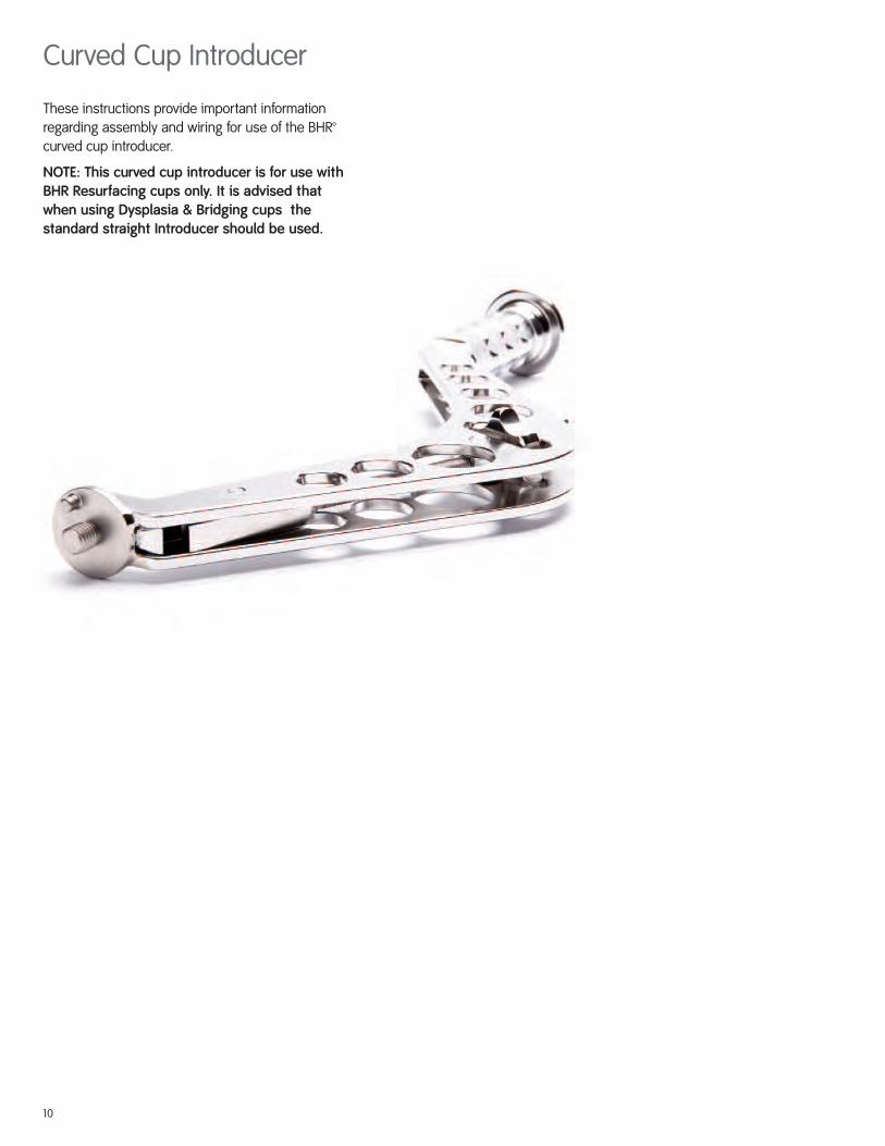
Curved Cup Introducer
These instructions provide important informationregarding assembly and wiring for use of the BHR™curved cup introducer.
NOTE: This curved cup introducer is for use withBHR Resurfacing cups only. It is advised thatwhen using Dysplasia & Bridging cups thestandard straight Introducer should be used.
10
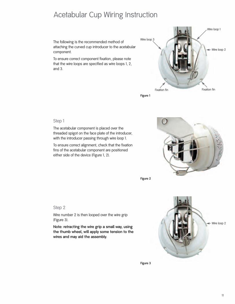
The following is the recommended method ofattaching the curved cup introducer to the acetabularcomponent.
To ensure correct component fixation, please notethat the wire loops are specified as wire loops 1, 2,and 3.
Step 1
The acetabular component is placed over thethreaded spigot on the face plate of the introducer,with the introducer passing through wire loop 1.
To ensure correct alignment, check that the fixationfins of the acetabular component are positionedeither side of the device (Figure 1, 2).
Step 2
Wire number 2 is then looped over the wire grip(Figure 3).
Note: retracting the wire grip a small way, usingthe thumb wheel, will apply some tension to thewires and may aid the assembly.
Figure 1
Figure 2
Figure 3
Wire loop 1
Fixation finFixation fin
Wire loop 2
Wire loop 2
Wire loop 3
Acetabular Cup Wiring Instruction
11
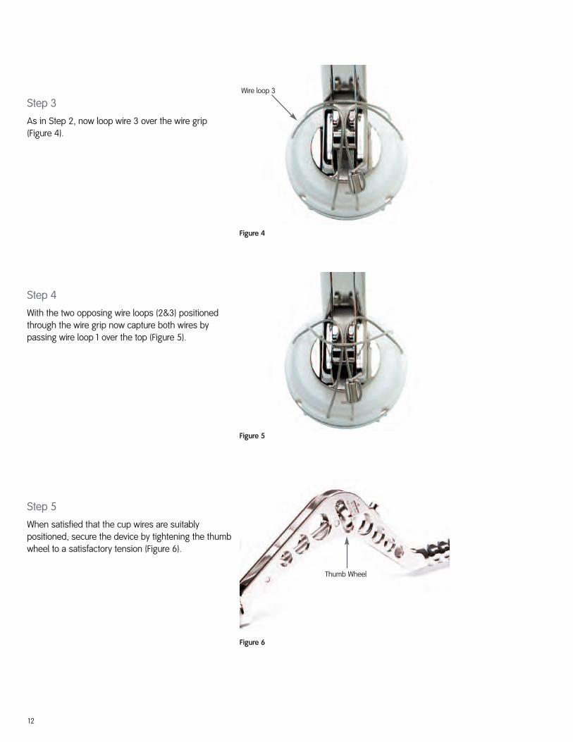
Step 3
As in Step 2, now loop wire 3 over the wire grip(Figure 4).
Step 4
With the two opposing wire loops (2&3) positionedthrough the wire grip now capture both wires bypassing wire loop 1 over the top (Figure 5).
Step 5
When satisfied that the cup wires are suitablypositioned, secure the device by tightening the thumbwheel to a satisfactory tension (Figure 6).
Figure 4
Figure 5
Figure 6
Wire loop 3
Thumb Wheel
12
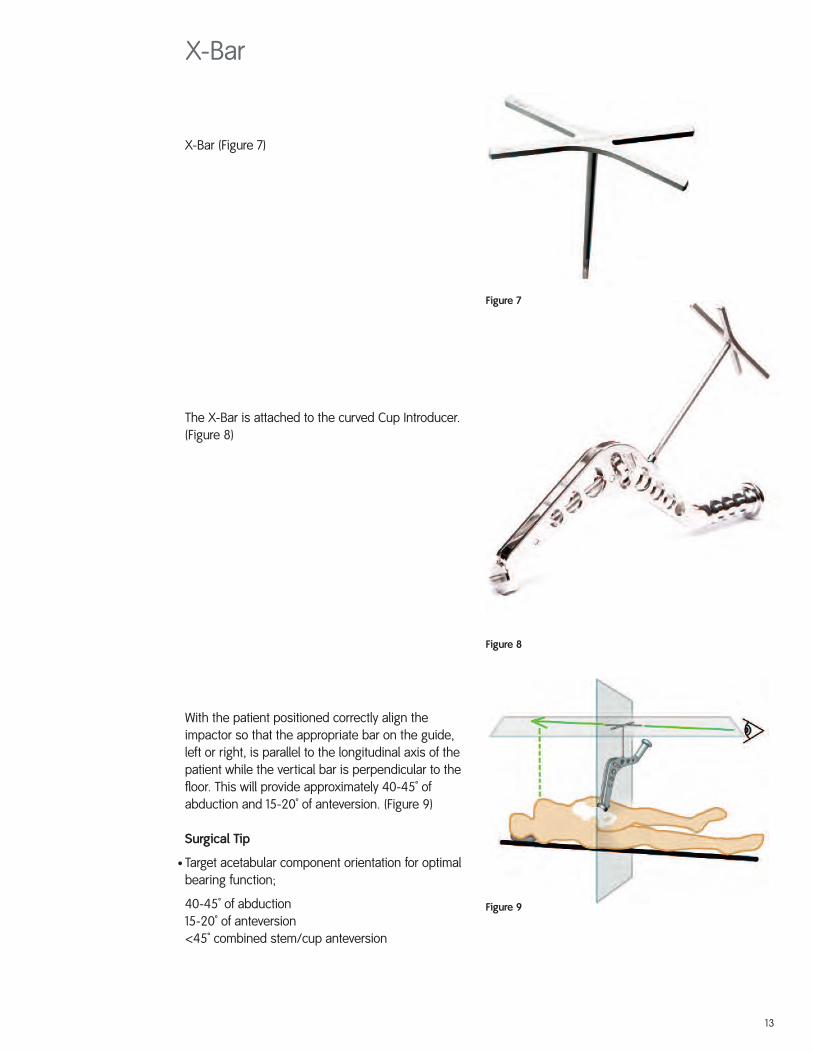
X-Bar (Figure 7)
The X-Bar is attached to the curved Cup Introducer.(Figure 8)
With the patient positioned correctly align theimpactor so that the appropriate bar on the guide,left or right, is parallel to the longitudinal axis of thepatient while the vertical bar is perpendicular to thefloor. This will provide approximately 40-45˚ ofabduction and 15-20˚ of anteversion. (Figure 9)
Surgical Tip
• Target acetabular component orientation for optimalbearing function;
40-45˚ of abduction15-20˚ of anteversion<45˚ combined stem/cup anteversion
Figure 7
Figure 8
Figure 9
X-Bar
13

Figure 1
Figure 2
Femoral Preparation
The desired position of the femoral alignment pin willbe known from the pre-operative templating. Identifythe tip of the greater trochanter through the tissueswith a spinal needle.
A ruler is used to measure the desired distancedown from the tip of the greater trochanter (Figure 1)and the alignment pin is inserted through the vastuslateralis fibres.
The front and back of the femoral shaft are felt andpin insertion is then started in a transverse directioninto the mid-lateral cortex (Figure 2).
14
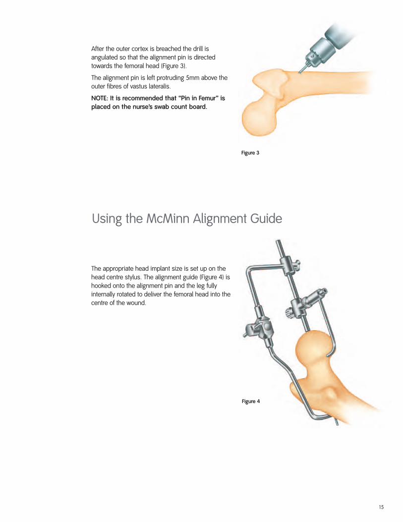
Figure 3
Figure 4
After the outer cortex is breached the drill isangulated so that the alignment pin is directedtowards the femoral head (Figure 3).
The alignment pin is left protruding 5mm above theouter fibres of vastus lateralis.
NOTE: It is recommended that “Pin in Femur” isplaced on the nurse’s swab count board.
The appropriate head implant size is set up on thehead centre stylus. The alignment guide (Figure 4) ishooked onto the alignment pin and the leg fullyinternally rotated to deliver the femoral head into thecentre of the wound.
Using the McMinn Alignment Guide
15
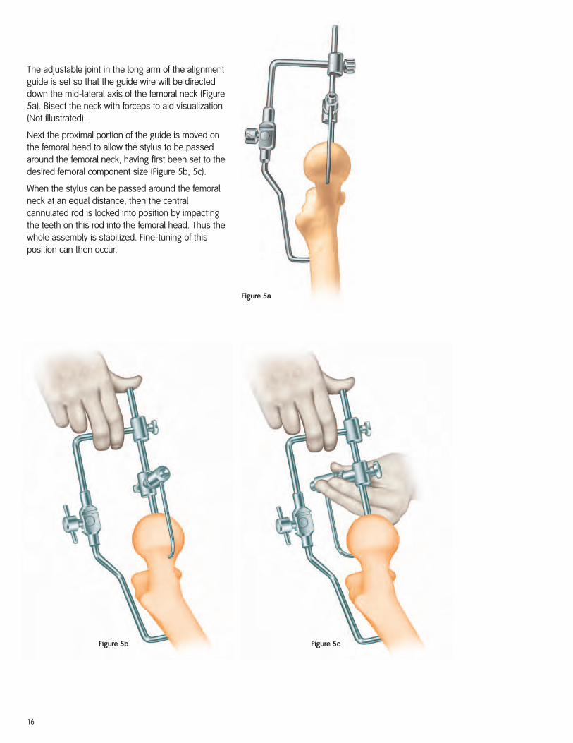
Figure 5a
Figure 5cFigure 5b
The adjustable joint in the long arm of the alignmentguide is set so that the guide wire will be directeddown the mid-lateral axis of the femoral neck (Figure5a). Bisect the neck with forceps to aid visualization(Not illustrated).
Next the proximal portion of the guide is moved onthe femoral head to allow the stylus to be passedaround the femoral neck, having first been set to thedesired femoral component size (Figure 5b, 5c).
When the stylus can be passed around the femoralneck at an equal distance, then the centralcannulated rod is locked into position by impactingthe teeth on this rod into the femoral head. Thus thewhole assembly is stabilized. Fine-tuning of thisposition can then occur.
16

Short Arm Alignment Jig Technique
Figure 6
Figure 7 - Short Arm Alignment Jig RulerIMAGE NOT TO SCALE
Figure 8 - Measuring Guide
10
20
30
40
50mm
9012-4120™Trademark of Smith & Nephew REV 0 06/06
Short Arm Alignment Jig Ruler
0120
A
B
C
TemplatingBHR™ template sets are used to determine componentsize and correct implant positioning. The position ofthe femoral component is a most important pre-operative consideration. Varus positioning must beavoided and slight valgus is recommended (Figure 6).
To achieve optimal femoral component positioning,place the appropriate BHR template onto the X-ray.Once satisfied with the size chosen the medial head-neck-junction may be identified to set up the correcttemplate positioning (A). This is aided by using thecut out section on the template which allows implantposition markings to be made with the template insitu.
With the head-neck-junction identified the template isrotated around this point until desired valgus positionis achieved with the implant’s centre line. One limitingfactor for implant positioning is the risk of femoralneck notching. This may be avoided at the templatingstage by confirming there is no contact between thesuperior aspect of the femoral neck and the template(B).
When the desired template position has beenachieved, the distance from the tip of the lessertrochanter to the centre line of the implant template ismeasured. The long axis of the ruler template (Figure7) is overlayed with the centre line of the implanttemplate to identify the pin insertion point on theintertrochanteric crest (C). This measurement istranslated intraoperatively onto the patient’s femurusing the measuring guide (Figure 8) to achieveoptimal pin, Jig and ultimately femoral implantpositioning. The pin insertion point may be markedusing electrocautery or a medical needle to ensureoptimal pin, jig and femoral positioning.
NOTE: To achieve correct measurement from thetip of the lower trochanter to the pin insertionpoint, the patient’s leg must not be externallyrotated while taking the X-ray in supine positionof the pelvis.
X-ray magnification must be taken into accountduring this preparation.
17
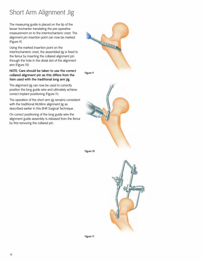
The measuring guide is placed on the tip of thelesser trochanter translating the pre-operativemeasurement on to the intertrochanteric crest. Thealignment pin insertion point can now be marked(Figure 9).
Using the marked insertion point on theintertrochanteric crest, the assembled jig is fixed tothe femur by inserting the collared alignment pinthrough the hole in the distal slot of the alignmentarm (Figure 10).
NOTE: Care should be taken to use the correctcollared alignment pin as this differs from theitem used with the traditional long arm jig.
The alignment jig can now be used to correctlyposition the long guide wire and ultimately achievecorrect implant positioning (Figure 11).
The operation of the short arm jig remains consistentwith the traditional McMinn alignment jig asdescribed earlier in this BHR Surgical Technique .
On correct positioning of the long guide wire thealignment guide assembly is released from the femurby first removing the collared pin.
Figure 9
Figure 10
Figure 11
Short Arm Alignment Jig
18
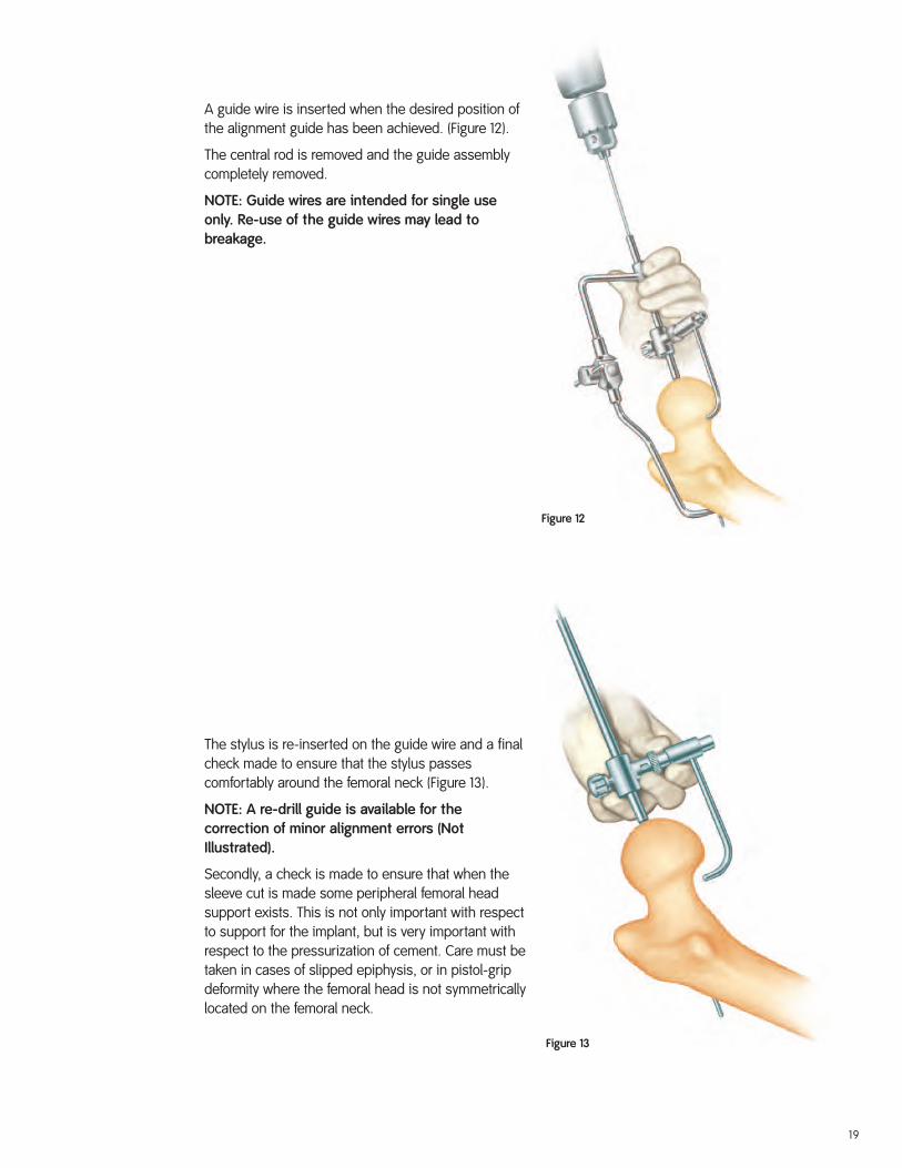
Figure 12
Figure 13
A guide wire is inserted when the desired position ofthe alignment guide has been achieved. (Figure 12).
The central rod is removed and the guide assemblycompletely removed.
NOTE: Guide wires are intended for single useonly. Re-use of the guide wires may lead tobreakage.
The stylus is re-inserted on the guide wire and a finalcheck made to ensure that the stylus passescomfortably around the femoral neck (Figure 13).
NOTE: A re-drill guide is available for thecorrection of minor alignment errors (NotIllustrated).
Secondly, a check is made to ensure that when thesleeve cut is made some peripheral femoral headsupport exists. This is not only important with respectto support for the implant, but is very important withrespect to the pressurization of cement. Care must betaken in cases of slipped epiphysis, or in pistol-gripdeformity where the femoral head is not symmetricallylocated on the femoral neck.
19
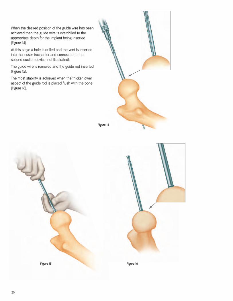
Figure 15 Figure 16
Figure 14
When the desired position of the guide wire has beenachieved then the guide wire is overdrilled to theappropriate depth for the implant being inserted(Figure 14).
At this stage a hole is drilled and the vent is insertedinto the lesser trochanter and connected to thesecond suction device (not illustrated).
The guide wire is removed and the guide rod inserted(Figure 15).
The most stability is achieved when the thicker loweraspect of the guide rod is placed flush with the bone(Figure 16).
20
Using the Sleeve Cutter Stop
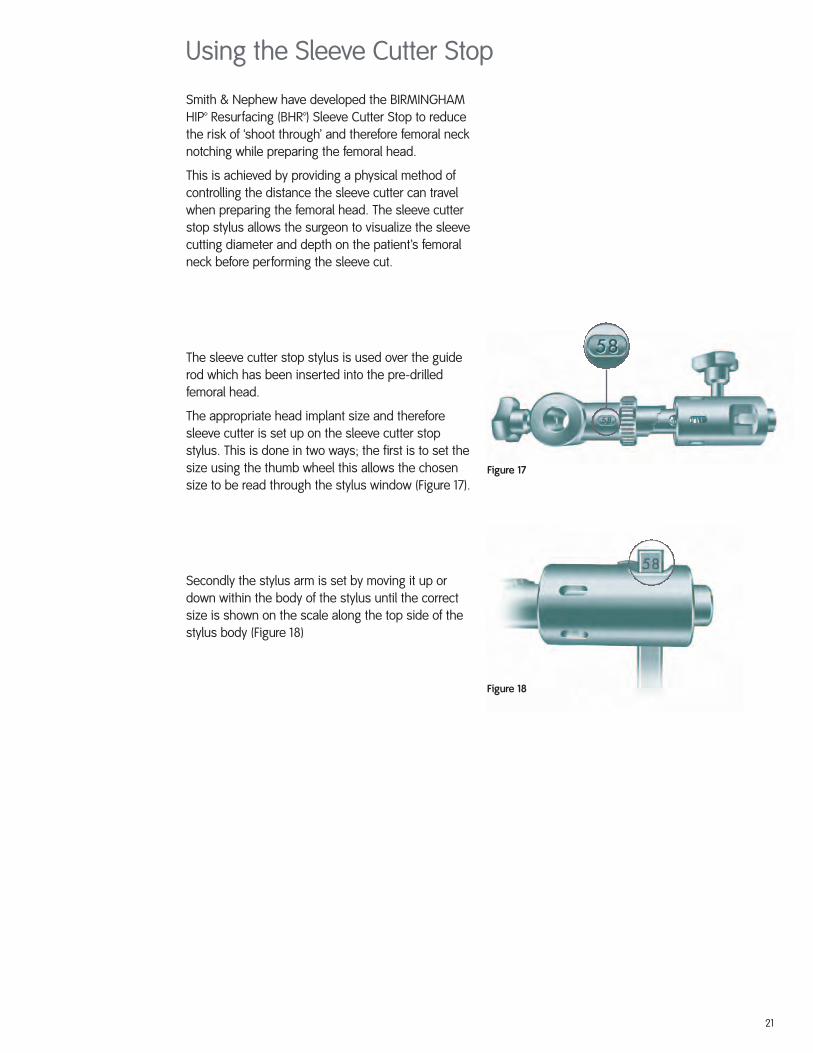
Smith & Nephew have developed the BIRMINGHAMHIP™ Resurfacing (BHR™) Sleeve Cutter Stop to reducethe risk of ‘shoot through’ and therefore femoral necknotching while preparing the femoral head.
This is achieved by providing a physical method ofcontrolling the distance the sleeve cutter can travelwhen preparing the femoral head. The sleeve cutterstop stylus allows the surgeon to visualize the sleevecutting diameter and depth on the patient’s femoralneck before performing the sleeve cut.
The sleeve cutter stop stylus is used over the guiderod which has been inserted into the pre-drilledfemoral head.
The appropriate head implant size and thereforesleeve cutter is set up on the sleeve cutter stopstylus. This is done in two ways; the first is to set thesize using the thumb wheel this allows the chosensize to be read through the stylus window (Figure 17).
Secondly the stylus arm is set by moving it up ordown within the body of the stylus until the correctsize is shown on the scale along the top side of thestylus body (Figure 18)
Figure 17
Figure 18
21
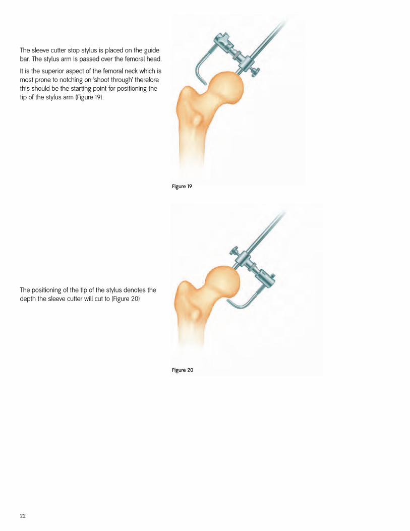
Figure 19
Figure 20
The sleeve cutter stop stylus is placed on the guidebar. The stylus arm is passed over the femoral head.
It is the superior aspect of the femoral neck which ismost prone to notching on ‘shoot through’ thereforethis should be the starting point for positioning thetip of the stylus arm (Figure 19).
The positioning of the tip of the stylus denotes thedepth the sleeve cutter will cut to (Figure 20)
22
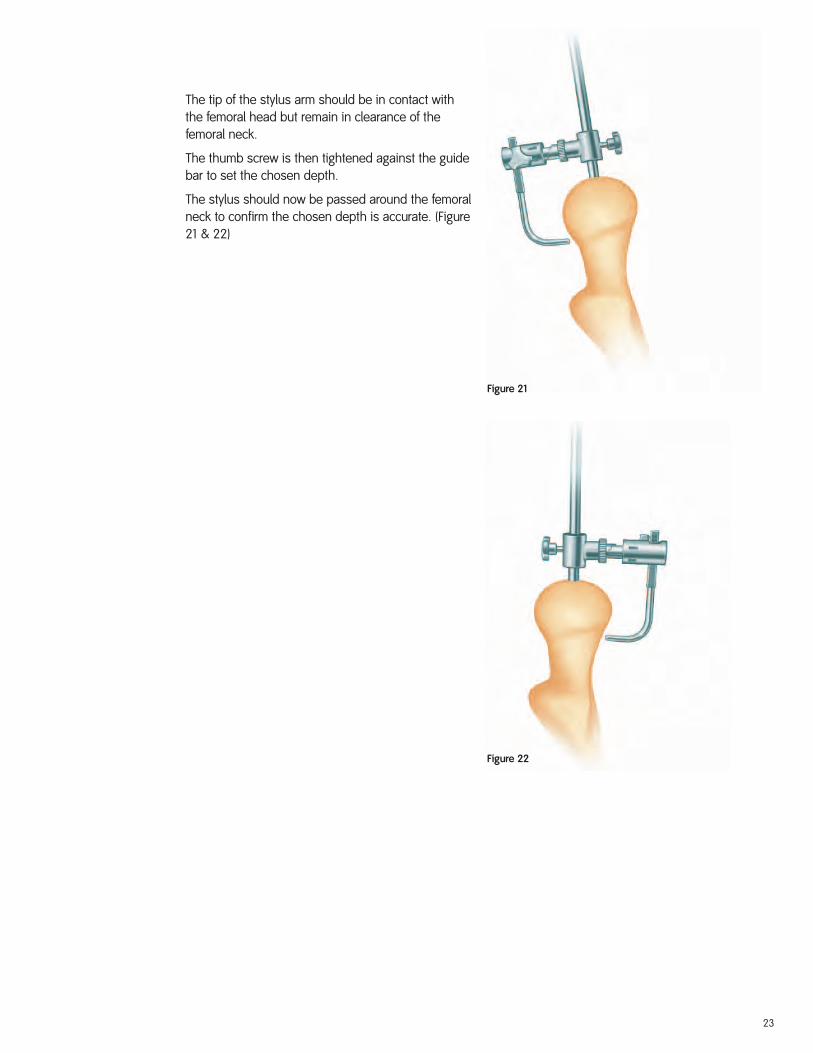
Figure 21
Figure 22
The tip of the stylus arm should be in contact withthe femoral head but remain in clearance of thefemoral neck.
The thumb screw is then tightened against the guidebar to set the chosen depth.
The stylus should now be passed around the femoralneck to confirm the chosen depth is accurate. (Figure21 & 22)
23
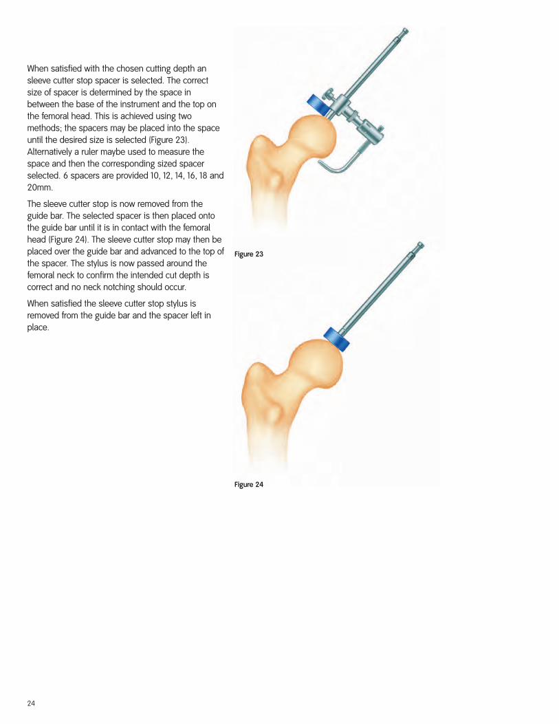
Figure 23
Figure 24
When satisfied with the chosen cutting depth ansleeve cutter stop spacer is selected. The correctsize of spacer is determined by the space inbetween the base of the instrument and the top onthe femoral head. This is achieved using twomethods; the spacers may be placed into the spaceuntil the desired size is selected (Figure 23).Alternatively a ruler maybe used to measure thespace and then the corresponding sized spacerselected. 6 spacers are provided 10, 12, 14, 16, 18 and20mm.
The sleeve cutter stop is now removed from theguide bar. The selected spacer is then placed ontothe guide bar until it is in contact with the femoralhead (Figure 24). The sleeve cutter stop may then beplaced over the guide bar and advanced to the top ofthe spacer. The stylus is now passed around thefemoral neck to confirm the intended cut depth iscorrect and no neck notching should occur.
When satisfied the sleeve cutter stop stylus isremoved from the guide bar and the spacer left inplace.
24
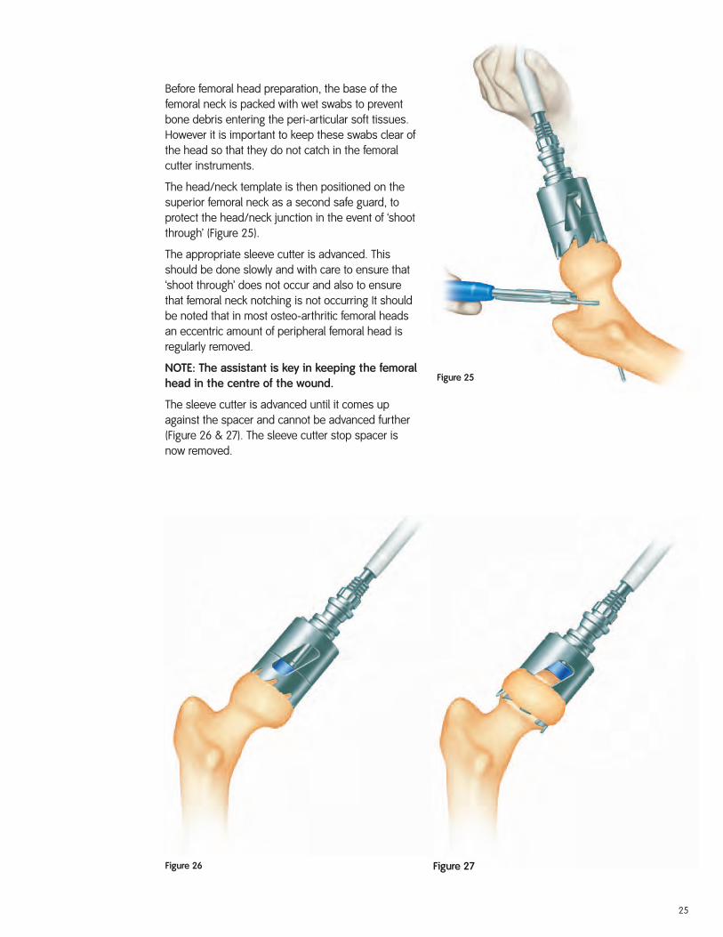
Figure 25
Before femoral head preparation, the base of thefemoral neck is packed with wet swabs to preventbone debris entering the peri-articular soft tissues.However it is important to keep these swabs clear ofthe head so that they do not catch in the femoralcutter instruments.
The head/neck template is then positioned on thesuperior femoral neck as a second safe guard, toprotect the head/neck junction in the event of ‘shootthrough’ (Figure 25).
The appropriate sleeve cutter is advanced. Thisshould be done slowly and with care to ensure that‘shoot through’ does not occur and also to ensurethat femoral neck notching is not occurring It shouldbe noted that in most osteo-arthritic femoral headsan eccentric amount of peripheral femoral head isregularly removed.
NOTE: The assistant is key in keeping the femoralhead in the centre of the wound.
The sleeve cutter is advanced until it comes upagainst the spacer and cannot be advanced further(Figure 26 & 27). The sleeve cutter stop spacer isnow removed.
Figure 26 Figure 27
25
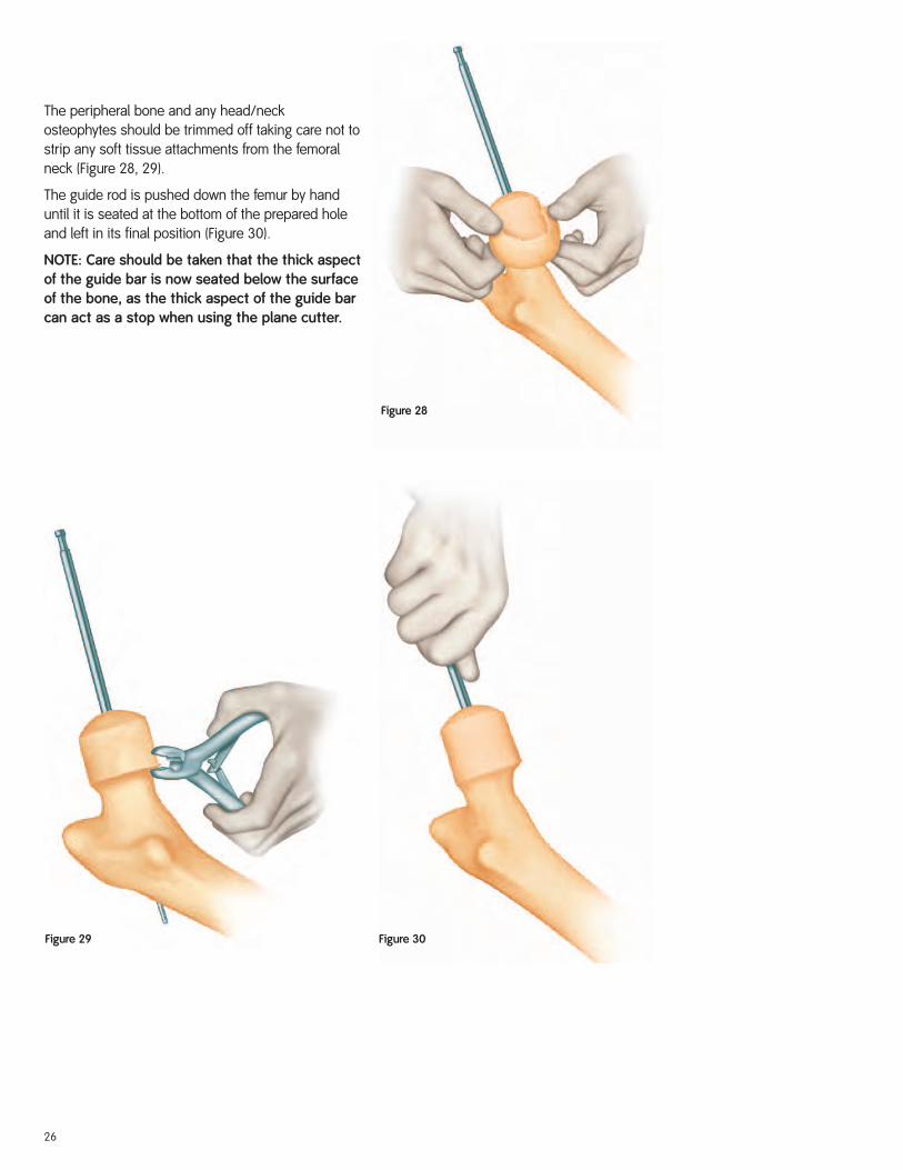
Figure 29 Figure 30
Figure 28
The peripheral bone and any head/neck osteophytes should be trimmed off taking care not tostrip any soft tissue attachments from the femoralneck (Figure 28, 29).
The guide rod is pushed down the femur by handuntil it is seated at the bottom of the prepared holeand left in its final position (Figure 30).
NOTE: Care should be taken that the thick aspectof the guide bar is now seated below the surfaceof the bone, as the thick aspect of the guide barcan act as a stop when using the plane cutter.
26
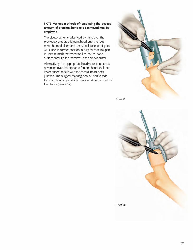
Figure 31
Figure 32
NOTE: Various methods of templating the desiredamount of proximal bone to be removed may beemployed.
The sleeve cutter is advanced by hand over thepreviously prepared femoral head until the teethmeet the medial femoral head/neck junction (Figure31). Once in correct position, a surgical marking penis used to mark the resection line on the bonesurface through the ‘window’ in the sleeve cutter.
Alternatively, the appropriate head/neck template isadvanced over the prepared femoral head until thelower aspect meets with the medial head-neckjunction. The surgical marking pen is used to markthe resection height which is indicated on the scale ofthe device (Figure 32).
27
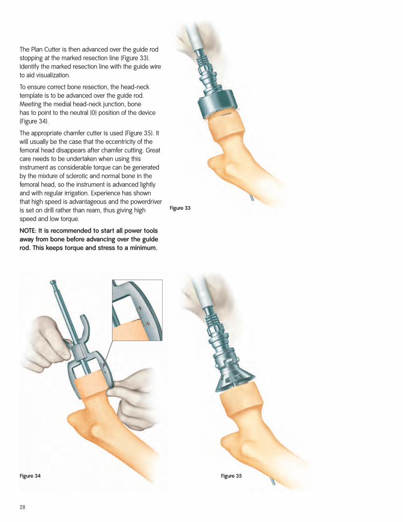
Figure 33
Figure 34 Figure 35
The Plan Cutter is then advanced over the guide rodstopping at the marked resection line (Figure 33).Identify the marked resection line with the guide wireto aid visualization.
To ensure correct bone resection, the head-necktemplate is to be advanced over the guide rod.Meeting the medial head-neck junction, bone has to point to the neutral (0) position of the device(Figure 34).
The appropriate chamfer cutter is used (Figure 35). Itwill usually be the case that the eccentricity of thefemoral head disappears after chamfer cutting. Greatcare needs to be undertaken when using thisinstrument as considerable torque can be generatedby the mixture of sclerotic and normal bone in thefemoral head, so the instrument is advanced lightlyand with regular irrigation. Experience has shownthat high speed is advantageous and the powerdriveris set on drill rather than ream, thus giving highspeed and low torque.
NOTE: It is recommended to start all power toolsaway from bone before advancing over the guiderod. This keeps torque and stress to a minimum.
28
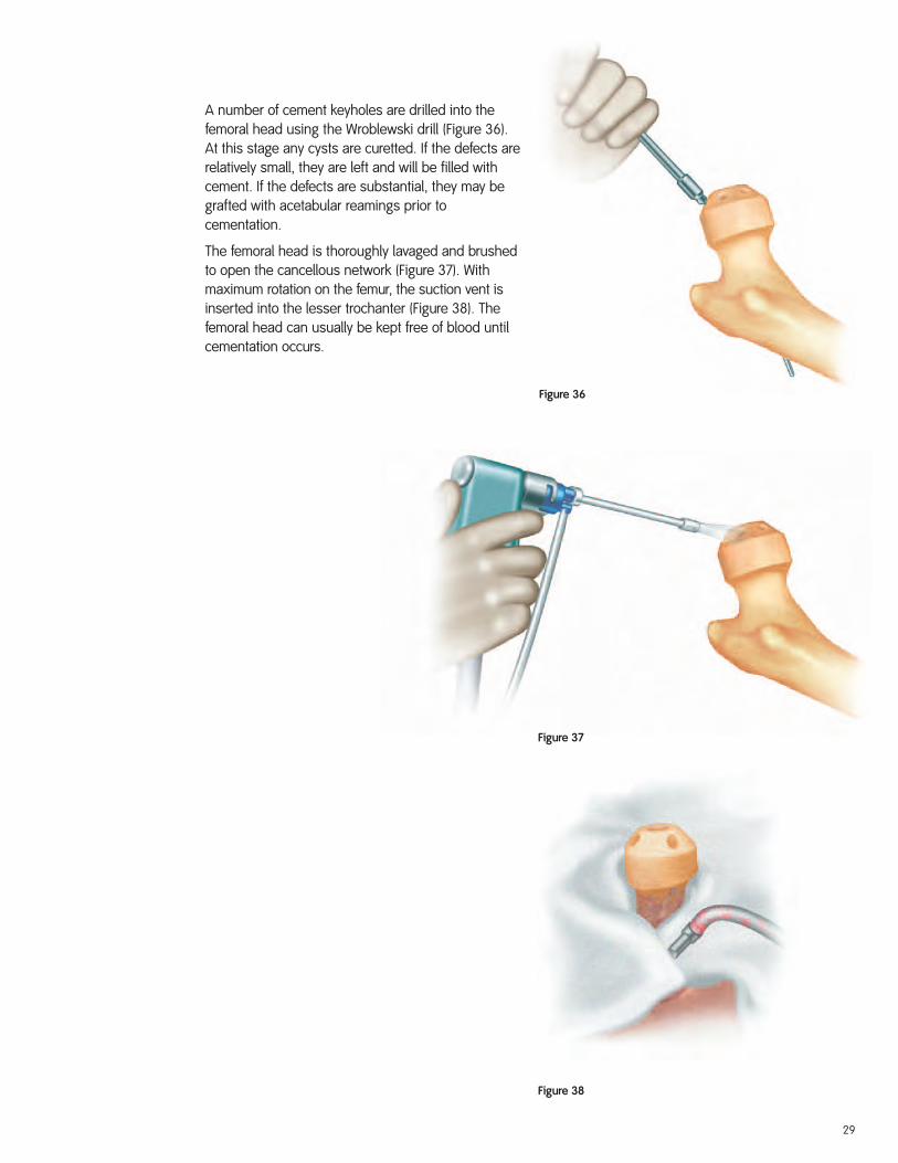
Figure 36
Figure 37
Figure 38
A number of cement keyholes are drilled into thefemoral head using the Wroblewski drill (Figure 36).At this stage any cysts are curetted. If the defects arerelatively small, they are left and will be filled withcement. If the defects are substantial, they may begrafted with acetabular reamings prior tocementation.
The femoral head is thoroughly lavaged and brushedto open the cancellous network (Figure 37). Withmaximum rotation on the femur, the suction vent isinserted into the lesser trochanter (Figure 38). Thefemoral head can usually be kept free of blood untilcementation occurs.
29
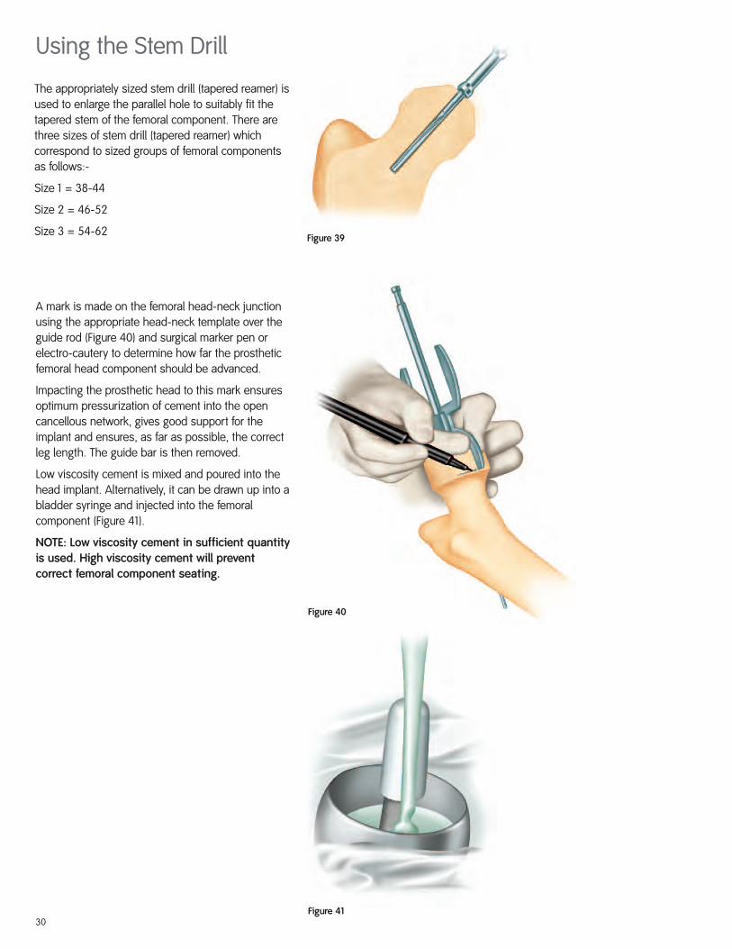
Figure 4130
Figure 40
A mark is made on the femoral head-neck junctionusing the appropriate head-neck template over theguide rod (Figure 40) and surgical marker pen orelectro-cautery to determine how far the prostheticfemoral head component should be advanced.
Impacting the prosthetic head to this mark ensuresoptimum pressurization of cement into the opencancellous network, gives good support for theimplant and ensures, as far as possible, the correctleg length. The guide bar is then removed.
Low viscosity cement is mixed and poured into thehead implant. Alternatively, it can be drawn up into abladder syringe and injected into the femoralcomponent (Figure 41).
NOTE: Low viscosity cement in sufficient quantityis used. High viscosity cement will preventcorrect femoral component seating.
Using the Stem Drill
Figure 39
The appropriately sized stem drill (tapered reamer) isused to enlarge the parallel hole to suitably fit thetapered stem of the femoral component. There arethree sizes of stem drill (tapered reamer) whichcorrespond to sized groups of femoral componentsas follows:-
Size 1 = 38-44
Size 2 = 46-52
Size 3 = 54-62

31
Figure 43
Figure 42
One minute after the start of cement mixing, thefemoral component is impacted into position to thepreviously made mark (Figure 42). It is important tohave a swab positioned anteriorly to collect anyextruded cement and to prevent this from flowinginto the acetabular component. It is important not toget this swab caught between the femoralcomponent and bone.
All extruded cement at the periphery of the femoralcomponent is removed. Any remaining osteophytesat the femoral head-neck junction are excised (Figure43) and the femoral head thoroughly cleaned withwet swabs and pulse lavage. The acetabularcomponent is also thoroughly cleaned with pulselavage and preparations made for reduction.
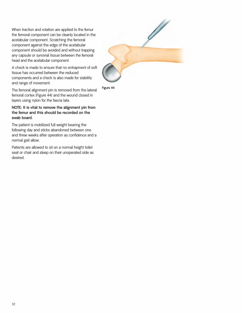
Figure 44
When traction and rotation are applied to the femurthe femoral component can be cleanly located in theacetabular component. Scratching the femoralcomponent against the edge of the acetabularcomponent should be avoided and without trappingany capsule or synovial tissue between the femoralhead and the acetabular component.
A check is made to ensure that no entrapment of softtissue has occurred between the reducedcomponents and a check is also made for stabilityand range of movement.
The femoral alignment pin is removed from the lateralfemoral cortex (Figure 44) and the wound closed inlayers using nylon for the fascia lata.
NOTE: It is vital to remove the alignment pin fromthe femur and this should be recorded on theswab board.
The patient is mobilized full weight bearing thefollowing day and sticks abandoned between oneand three weeks after operation as confidence and anormal gait allow.
Patients are allowed to sit on a normal height toiletseat or chair and sleep on their unoperated side asdesired.
32
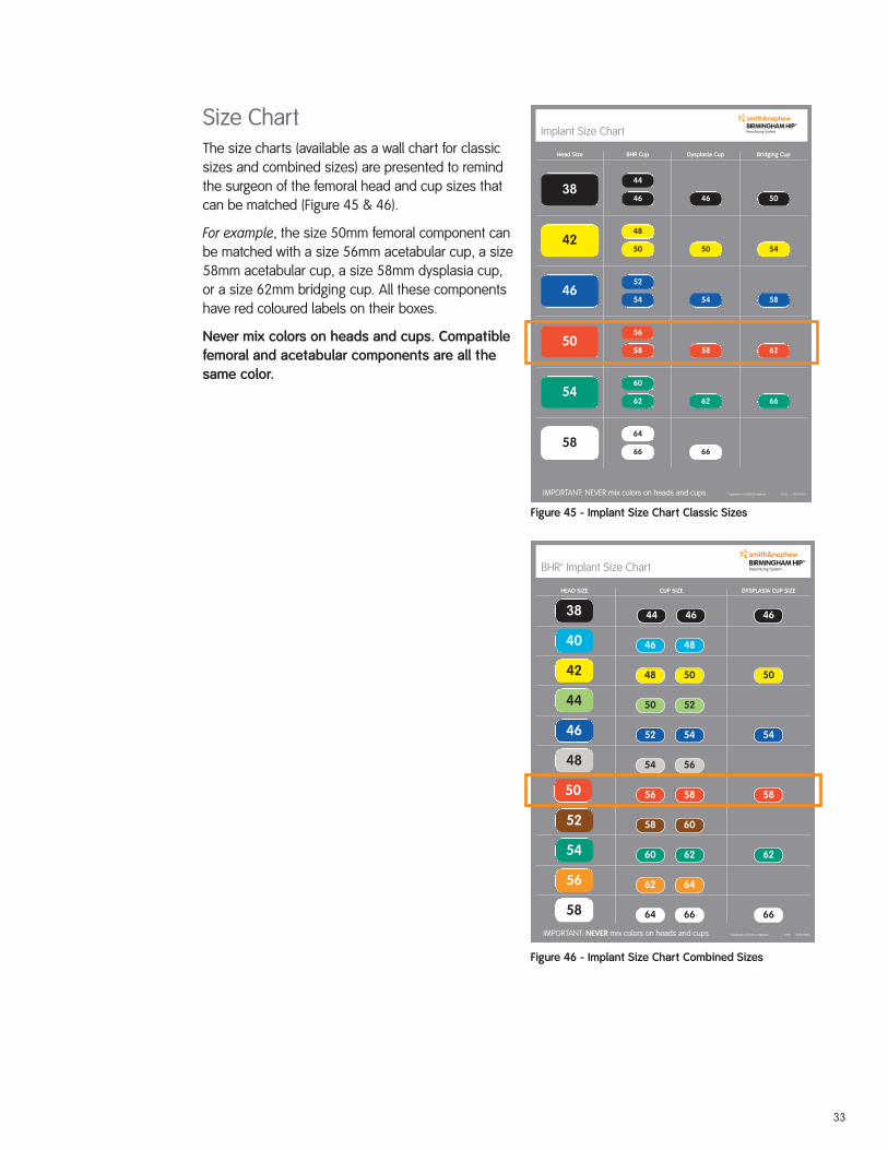
Implant Size Chart
™ Trademark of Smith & Nephew 11/05 0216-1903
Head Size BHR Cup Dysplasia Cup Bridging Cup
IMPORTANT: NEVER mix colors on heads and cups.
3844
46 46 50
4248
50 50 54
4652
54 54 58
5056
58 58 62
5460
62 62 66
5864
66 66
Figure 45 - Implant Size Chart Classic Sizes
Size ChartThe size charts (available as a wall chart for classicsizes and combined sizes) are presented to remindthe surgeon of the femoral head and cup sizes thatcan be matched (Figure 45 & 46).
For example, the size 50mm femoral component canbe matched with a size 56mm acetabular cup, a size58mm acetabular cup, a size 58mm dysplasia cup,or a size 62mm bridging cup. All these componentshave red coloured labels on their boxes.
Never mix colors on heads and cups. Compatiblefemoral and acetabular components are all thesame color.
38 44 46 46
40 46 48
42 48 50 50
44 50 52
46 52 54 54
48 54 56
50 56 58 58
52 58 60
54 60 62 62
56 62 64
58 64 66 66
BHR™ Implant Size Chart
™ Trademark of Smith & Nephew 11/05 0216-0920
HEAD SIZE CUP SIZE DYSPLASIA CUP SIZE
IMPORTANT: NEVER mix colors on heads and cups.
Figure 46 - Implant Size Chart Combined Sizes
33
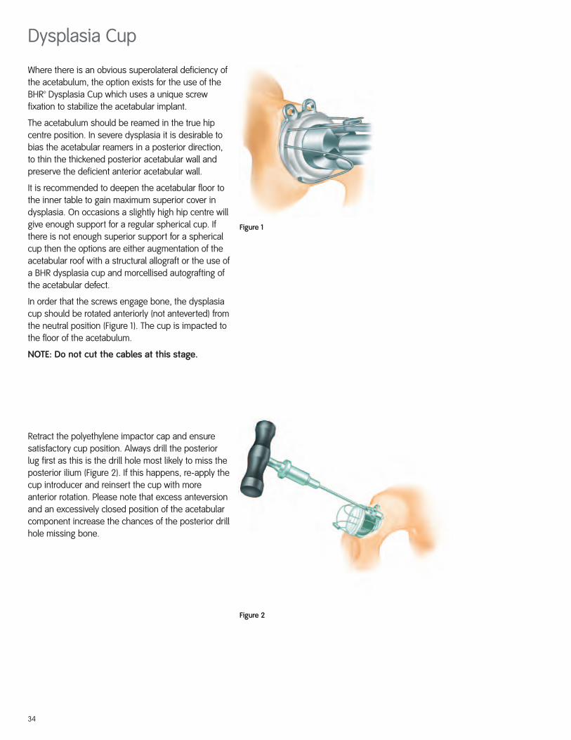
Where there is an obvious superolateral deficiency ofthe acetabulum, the option exists for the use of theBHR™ Dysplasia Cup which uses a unique screwfixation to stabilize the acetabular implant.
The acetabulum should be reamed in the true hipcentre position. In severe dysplasia it is desirable tobias the acetabular reamers in a posterior direction,to thin the thickened posterior acetabular wall andpreserve the deficient anterior acetabular wall.
It is recommended to deepen the acetabular floor tothe inner table to gain maximum superior cover indysplasia. On occasions a slightly high hip centre willgive enough support for a regular spherical cup. Ifthere is not enough superior support for a sphericalcup then the options are either augmentation of theacetabular roof with a structural allograft or the use ofa BHR dysplasia cup and morcellised autografting ofthe acetabular defect.
In order that the screws engage bone, the dysplasiacup should be rotated anteriorly (not anteverted) fromthe neutral position (Figure 1). The cup is impacted tothe floor of the acetabulum.
NOTE: Do not cut the cables at this stage.
Retract the polyethylene impactor cap and ensuresatisfactory cup position. Always drill the posteriorlug first as this is the drill hole most likely to miss theposterior ilium (Figure 2). If this happens, re-apply thecup introducer and reinsert the cup with moreanterior rotation. Please note that excess anteversionand an excessively closed position of the acetabularcomponent increase the chances of the posterior drillhole missing bone.
Figure 1
Figure 2
Dysplasia Cup
34
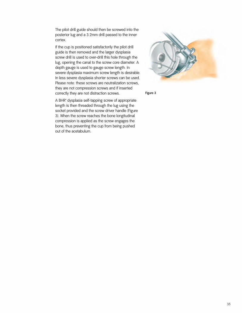
The pilot drill guide should then be screwed into theposterior lug and a 3.2mm drill passed to the innercortex.
If the cup is positioned satisfactorily the pilot drillguide is then removed and the larger dysplasiascrew drill is used to over-drill this hole through thelug, opening the canal to the screw core diameter. Adepth gauge is used to gauge screw length. Insevere dysplasia maximum screw length is desirable.In less severe dysplasia shorter screws can be used.Please note: these screws are neutralization screws,they are not compression screws and if insertedcorrectly they are not distraction screws.
A BHR™ dysplasia self-tapping screw of appropriatelength is then threaded through the lug using thesocket provided and the screw driver handle (Figure3). When the screw reaches the bone longitudinalcompression is applied as the screw engages thebone, thus preventing the cup from being pushedout of the acetabulum.
Figure 3
35
Once the screw is securely fixed in bone then powermay be used to drive the screw home. This requiresthe high torque ream setting.
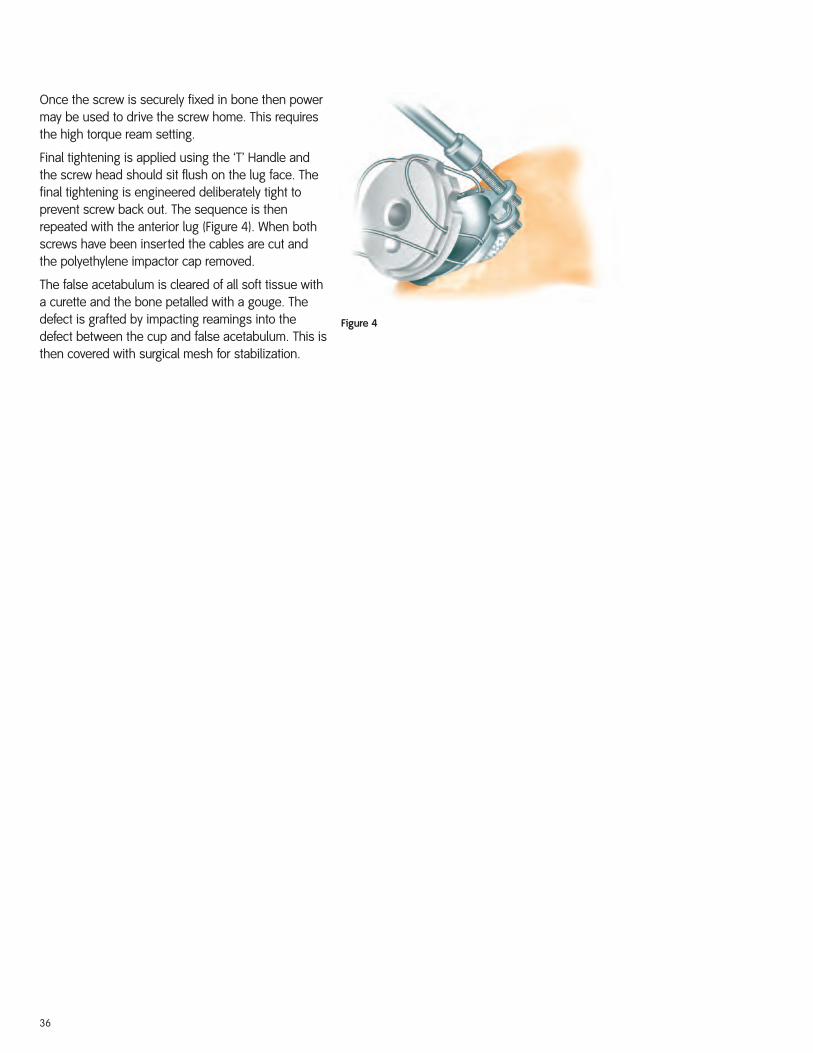
Final tightening is applied using the ‘T’ Handle andthe screw head should sit flush on the lug face. Thefinal tightening is engineered deliberately tight toprevent screw back out. The sequence is thenrepeated with the anterior lug (Figure 4). When bothscrews have been inserted the cables are cut andthe polyethylene impactor cap removed.
The false acetabulum is cleared of all soft tissue witha curette and the bone petalled with a gouge. Thedefect is grafted by impacting reamings into thedefect between the cup and false acetabulum. This isthen covered with surgical mesh for stabilization.
Figure 4
36
With acetabular dysplasia the surgeon has toexercise judgement regarding the post-operativeweight-bearing regime. In severe dysplasia werecommend keeping the patients partial weight-bearing, using elbow crutches for six months, but inless severe dysplasia full weight bearing is permittedfrom the first post-operative day.
A typical regime for moderate dysplasia is partialweight bearing using elbow crutches for six weeks,followed by two sticks with gradually increasingactivity over the next six weeks. We now havehistological evidence of impressive bone ingrowthinto the hydroxyapatite coated POROCAST™ bone in-growth cup surface at six weeks. However, in severedysplasia we recommend to see radiographicevidence of bone graft incorporation in the falseacetabulum before allowing the patient to becomefully active.
Additional screw fixation of the acetabularcomponent by utilizing the dysplasia cup may bedesirable in certain non-dysplastic acetabulae.For example, in old fractures of the posterioracetabular wall, the bridging acetabular cup(useful in gross femoral head/acetabulum sizemis-match) also has superolateral lugs for screwfixation. In these non-dysplastic acetabulae, theedge of the superior acetabulum impinges on thelugs, thus preventing complete seating of theacetabular component. Therefore the operatingsurgeon may utilize a surgical burr to facilitateplacement of the lugs without compromising theacetabular orientation.
37
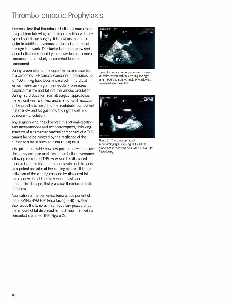
Figure 2 - Trans-oesophageal echocardiograph showing reduced fatembolization following a BIRMINGHAM HIP™Resurfacing.
RA
RV
RA RV
Figure 1 - Snowstorm appearance of majorfat embolization with fat entering the rightatrium (RA) and right ventricle (RV) followingcemented stemmed THR.
It seems clear that thrombo-embolism is much moreof a problem following hip arthroplasty than with anytype of soft tissue surgery. It is obvious that somefactor in addition to venous stasis and endothelialdamage is at work. This factor is bone marrow andfat embolization caused by the insertion of a femoralcomponent, particularly a cemented femoralcomponent.
During preparation of the upper femur and insertionof a cemented THR femoral component, pressures upto 1400mm Hg have been measured in the distalfemur. These very high intramedullary pressuresdisplace marrow and fat into the venous circulation.During hip dislocation from all surgical approachesthe femoral vein is kinked and it is not until reductionof the prosthetic head into the acetabular componentthat marrow and fat gush into the right heart andpulmonary circulation.
Any surgeon who has observed this fat embolizationwith trans-oesophageal echocardiography followinginsertion of a cemented femoral component of a THRcannot fail to be amazed by the resilience of thehuman to survive such an assault. (Figure 1).
It is quite remarkable how few patients develop acutecirculatory collapse or clinical fat embolism syndromefollowing cemented THR. However this displacedmarrow is rich in tissue thromboplastin and this actsas a potent activator of the clotting system. It is thisactivation of the clotting cascade by displaced fatand marrow, in addition to venous stasis andendothelial damage, that gives our thrombo-embolicproblems.
Application of the cemented femoral component ofthe BIRMINGHAM HIP™ Resurfacing (BHR™) Systemalso raises the femoral intra-medullary pressure, butthe amount of fat displaced is much less than with acemented stemmed THR (Figure 2).
Thrombo-embolic Prophylaxis
38
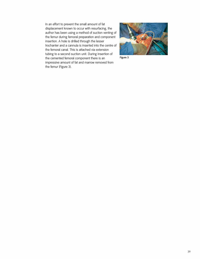
Figure 3
In an effort to prevent the small amount of fatdisplacement known to occur with resurfacing, theauthor has been using a method of suction venting ofthe femur during femoral preparation and componentinsertion. A hole is drilled through the lessertrochanter and a cannula is inserted into the centre ofthe femoral canal. This is attached via extensiontubing to a second suction unit. During insertion ofthe cemented femoral component there is animpressive amount of fat and marrow removed fromthe femur (Figure 3).
39
Acetabular Cup Extraction Kit (Cat. no. 900-201)
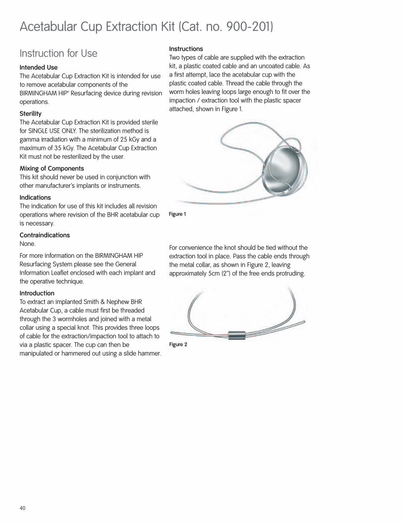
Instructions Two types of cable are supplied with the extractionkit, a plastic coated cable and an uncoated cable. Asa first attempt, lace the acetabular cup with theplastic coated cable. Thread the cable through theworm holes leaving loops large enough to fit over theimpaction / extraction tool with the plastic spacerattached, shown in Figure 1.
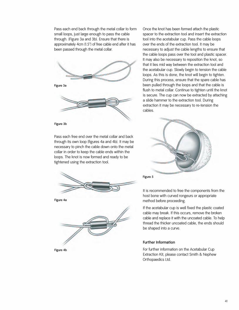
For convenience the knot should be tied without theextraction tool in place. Pass the cable ends throughthe metal collar, as shown in Figure 2, leavingapproximately 5cm (2”) of the free ends protruding.
Figure 2
Figure 1
Instruction for UseIntended UseThe Acetabular Cup Extraction Kit is intended for useto remove acetabular components of theBIRMINGHAM HIP™ Resurfacing device during revisionoperations.
SterilityThe Acetabular Cup Extraction Kit is provided sterilefor SINGLE USE ONLY. The sterilization method isgamma irradiation with a minimum of 25 kGy and amaximum of 35 kGy. The Acetabular Cup ExtractionKit must not be resterilized by the user.
Mixing of ComponentsThis kit should never be used in conjunction withother manufacturer’s implants or instruments.
IndicationsThe indication for use of this kit includes all revisionoperations where revision of the BHR acetabular cupis necessary.
ContraindicationsNone.
For more information on the BIRMINGHAM HIPResurfacing System please see the GeneralInformation Leaflet enclosed with each implant andthe operative technique.
IntroductionTo extract an implanted Smith & Nephew BHRAcetabular Cup, a cable must first be threadedthrough the 3 wormholes and joined with a metalcollar using a special knot. This provides three loopsof cable for the extraction/impaction tool to attach tovia a plastic spacer. The cup can then bemanipulated or hammered out using a slide hammer.
40
Pass each end back through the metal collar to formsmall loops, just large enough to pass the cablethrough. (Figure 3a and 3b). Ensure that there isapproximately 4cm (1.5”) of free cable end after it hasbeen passed through the metal collar.
Pass each free end over the metal collar and backthrough its own loop (figures 4a and 4b). It may benecessary to pinch the cable down onto the metalcollar in order to keep the cable ends within theloops. The knot is now formed and ready to betightened using the extraction tool.
Once the knot has been formed attach the plasticspacer to the extraction tool and insert the extractiontool into the acetabular cup. Pass the cable loopsover the ends of the extraction tool. It may benecessary to adjust the cable lengths to ensure thatthe cable loops pass over the tool and plastic spacer.It may also be necessary to reposition the knot, sothat it lies mid way between the extraction tool andthe acetabular cup. Slowly begin to tension the cableloops. As this is done, the knot will begin to tighten.During this process, ensure that the spare cable hasbeen pulled through the loops and that the cable isflush to metal collar. Continue to tighten until the knotis secure. The cup can now be extracted by attachinga slide hammer to the extraction tool. Duringextraction it may be necessary to re-tension thecables.
It is recommended to free the components from thehost bone with curved rongeurs or appropriatemethod before proceeding.
If the acetabular cup is well fixed the plastic coatedcable may break. If this occurs, remove the brokencable and replace it with the uncoated cable. To helpthread the thicker uncoated cable, the ends shouldbe shaped into a curve.
Further Information
For further information on the Acetabular CupExtraction Kit, please contact Smith & NephewOrthopaedics Ltd.
Figure 3a
Figure 3b
Figure 4a
Figure 4b
Figure 5
41
Catalog
BHR™ Resurfacing HeadCat. No. Size
74121138 38mm74123140 40mm74121142 42 mm74123144 44mm74121146 46mm74123148 48mm74121150 50mm74123152 52mm74121154 54mm74123156 56mm74121158 58mm
BHR Acetabular CupCat. No. Size
74120144 44mm (38 head)74120146 46mm (38 head)74122146 46mm (40 head)74122148 48mm (40 head)74120148 48mm (42 head)74120150 50mm (42 head)74122050 50mm (44 head)74122152 52mm (44 head)74120152 52mm (46 head)74120154 54mm (46 head)74122154 54mm (48 head)74122156 56mm (48 head)74120156 56mm (50 head)74120158 58mm (50 head)74122158 58mm (52 head)74122160 60mm (52 head)74120160 60mm (54 head)74120162 62mm (54 head)74122162 62mm (56 head)74122164 64mm (56 head)74120164 64mm (58 head)74120166 66mm (58 head)
42
BHR Dysplasia CupCat. No. Size
74120246 46mm74122248 48mm74120250 50mm74122252 52mm74120254 54mm74122256 56mm74120258 58mm74122260 60mm74120262 62mm74122264 64mm74120266 66mm
BHR Bridging CupCat. No. Size
74120350 50mm74122352 52mm74120354 54mm74122356 56mm74120358 58mm74122360 60mm74120362 62mm74122364 64mm74120366 66mm
BHR Cup ScrewCat. No. Size
74500024 24mm74500028 28mm74500032 32mm74500036 36mm74500040 40mm74500044 44mm74500048 48mm74500052 52mm74500056 56mm74500060 60mm74500064 64mm74500068 68mm74500072 72mm74500076 76mm74500080 80mm74500084 84mm74500088 88mm
43
Warnings and Precautions
DEVICE DESCRIPTIONThe BIRMINGHAM HIP Resurfacing (BHR) prosthesis is a metal-on-metal hip resurfacing prosthesis.The device consists of a stemmed femoral head resurfacing component designed for cementedfixation, and a hemispherical acetabular cup designed for cementless, press-fit, fixation. Theacetabular cups are configured in one-piece designs and modular designs. Instrumentation sets areprovided as standard; several additional instruments are available as options.
Resurfacing Femoral Head The resurfacing femoral head is supplied in a range of eleven sizes, and is manufactured from CoCralloy. The femoral head central stem is parametric and varies proportionally with the external diameter.There are 6 equally spaced internal recesses intended to provide antirotational locking for the cementmantle.
Acetabular Cups - One-PieceThe standard acetabular component is supplied in a range of twenty two sizes (two for each femoralhead size to address the condition of occasional head cup mismatch). For those patients with adeficiency in the superolateral aspect of the acetabulum, the dysplasia cup is available. The dysplasiacup is designed with two superolateral screw holes that accommodate CoCr-alloy dysplasia cupscrews. There is a range of eleven sizes for the dysplasia cup. A bridging cup is designed with athicker wall section than the dysplasia cup to allow for mismatch between femoral head size andsurgically prepared acetabulum. The bridging cup is also designed with two superolateral screw holesthat accommodate the CoCr-alloy dysplasia cup screws. The bridging cup is available in ten sizes. Allone-piece acetabular cups have a single layer of integrally-cast CoCr-alloy (ASTM F75 and ISO 5832-4)beads on the outer surface that are coated with hydroxyapatite (HA) (ASTM F1185).
Acetabular Cups - ModularThe R3™ Acetabular Shells are supplied in a range of ten sizes (accommodating femoral heads in sizesfrom 38mm to 54mm) and in versions with and without acetabular screw holes. The R3 AcetabularShells contain an asymmetric porous beaded coating (STIKTITE™). The mating R3 Metal Liner isassembled to the R3 Acetabular Shell through a taper locking mechanism. The R3 Metal Liners areavailable in nine sizes to accommodate BHR Femoral Heads from 38mm through 54mm.
Screws for One-Piece CupsThe dysplasia cup screws are threaded through a threaded lug on the superolateral aspect of eitherthe dysplasia or bridging cup and lock in situ. The screws also lock into the posterior cortical bone ofthe ilium. Screws are available in sizes ranging from 24mm to 88mm, in 4mm increments.
Screws and Plugs for Modular CupsThe R3 Acetabular Shells with acetabular screw holes are compatible with Spherical Head Screws,which are available in lengths of 15, 20, 25, 30, 35, 40, 45, 50, 60, and 70mm. If the surgeon wishes toseal the apex hole or any unused acetabular screw holes, Screw Hole Covers and Apex Hole Coverscan be used.
Materials
Sizing and System Compatibility – One-Piece Acetabular Cups Each femoral head resurfacing component is compatible with two standard acetabular cup sizes andone dysplasia or bridging cup size (Table 1).
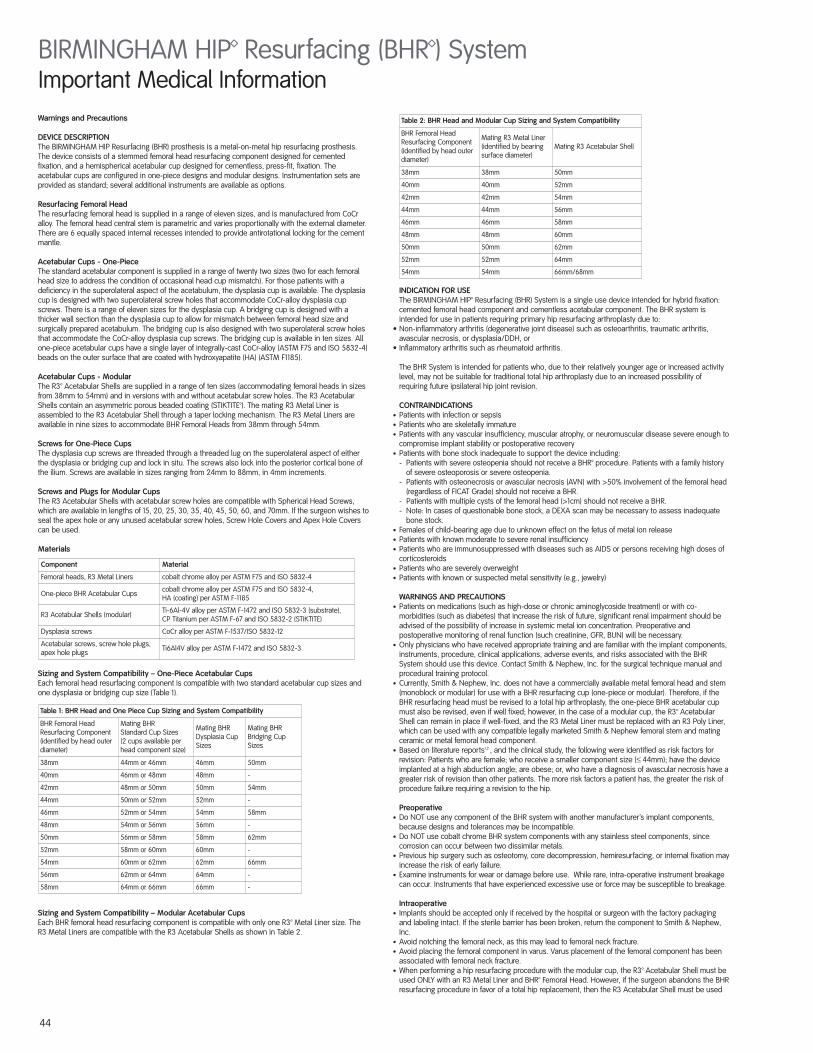
Sizing and System Compatibility – Modular Acetabular Cups Each BHR femoral head resurfacing component is compatible with only one R3™ Metal Liner size. TheR3 Metal Liners are compatible with the R3 Acetabular Shells as shown in Table 2.
INDICATION FOR USEThe BIRMINGHAM HIP™ Resurfacing (BHR) System is a single use device intended for hybrid fixation:cemented femoral head component and cementless acetabular component. The BHR system isintended for use in patients requiring primary hip resurfacing arthroplasty due to:
• Non-inflammatory arthritis (degenerative joint disease) such as osteoarthritis, traumatic arthritis,avascular necrosis, or dysplasia/DDH, or
• Inflammatory arthritis such as rheumatoid arthritis.
The BHR System is intended for patients who, due to their relatively younger age or increased activitylevel, may not be suitable for traditional total hip arthroplasty due to an increased possibility ofrequiring future ipsilateral hip joint revision.
CONTRAINDICATIONS∑ Patients with infection or sepsis∑ Patients who are skeletally immature∑ Patients with any vascular insufficiency, muscular atrophy, or neuromuscular disease severe enough to
compromise implant stability or postoperative recovery∑ Patients with bone stock inadequate to support the device including:
- Patients with severe osteopenia should not receive a BHR™ procedure. Patients with a family historyof severe osteoporosis or severe osteopenia.
- Patients with osteonecrosis or avascular necrosis (AVN) with >50% involvement of the femoral head(regardless of FICAT Grade) should not receive a BHR.
- Patients with multiple cysts of the femoral head (>1cm) should not receive a BHR.- Note: In cases of questionable bone stock, a DEXA scan may be necessary to assess inadequate
bone stock.∑ Females of child-bearing age due to unknown effect on the fetus of metal ion release∑ Patients with known moderate to severe renal insufficiency∑ Patients who are immunosuppressed with diseases such as AIDS or persons receiving high doses of
corticosteroids∑ Patients who are severely overweight∑ Patients with known or suspected metal sensitivity (e.g., jewelry)
WARNINGS AND PRECAUTIONS ∑ Patients on medications (such as high-dose or chronic aminoglycoside treatment) or with co-
morbidities (such as diabetes) that increase the risk of future, significant renal impairment should beadvised of the possibility of increase in systemic metal ion concentration. Preoperative andpostoperative monitoring of renal function (such creatinine, GFR, BUN) will be necessary.
∑ Only physicians who have received appropriate training and are familiar with the implant components,instruments, procedure, clinical applications, adverse events, and risks associated with the BHRSystem should use this device. Contact Smith & Nephew, Inc. for the surgical technique manual andprocedural training protocol.
∑ Currently, Smith & Nephew, Inc. does not have a commercially available metal femoral head and stem(monoblock or modular) for use with a BHR resurfacing cup (one-piece or modular). Therefore, if theBHR resurfacing head must be revised to a total hip arthroplasty, the one-piece BHR acetabular cupmust also be revised, even if well fixed; however, in the case of a modular cup, the R3™ AcetabularShell can remain in place if well-fixed, and the R3 Metal Liner must be replaced with an R3 Poly Liner,which can be used with any compatible legally marketed Smith & Nephew femoral stem and matingceramic or metal femoral head component.
∑ Based on literature reports1,2 , and the clinical study, the following were identified as risk factors forrevision: Patients who are female; who receive a smaller component size (≤ 44mm); have the deviceimplanted at a high abduction angle; are obese; or, who have a diagnosis of avascular necrosis have agreater risk of revision than other patients. The more risk factors a patient has, the greater the risk ofprocedure failure requiring a revision to the hip.
Preoperative∑ Do NOT use any component of the BHR system with another manufacturer’s implant components,
because designs and tolerances may be incompatible. ∑ Do NOT use cobalt chrome BHR system components with any stainless steel components, since
corrosion can occur between two dissimilar metals. ∑ Previous hip surgery such as osteotomy, core decompression, hemiresurfacing, or internal fixation may
increase the risk of early failure.∑ Examine instruments for wear or damage before use. While rare, intra-operative instrument breakage
can occur. Instruments that have experienced excessive use or force may be susceptible to breakage.
Intraoperative∑ Implants should be accepted only if received by the hospital or surgeon with the factory packaging
and labeling intact. If the sterile barrier has been broken, return the component to Smith & Nephew,Inc.
∑ Avoid notching the femoral neck, as this may lead to femoral neck fracture.∑ Avoid placing the femoral component in varus. Varus placement of the femoral component has been
associated with femoral neck fracture. ∑ When performing a hip resurfacing procedure with the modular cup, the R3™ Acetabular Shell must be
used ONLY with an R3 Metal Liner and BHR™ Femoral Head. However, if the surgeon abandons the BHRresurfacing procedure in favor of a total hip replacement, then the R3 Acetabular Shell must be used
BIRMINGHAM HIP™ Resurfacing (BHR™) SystemImportant Medical Information
Component Material
Femoral heads, R3 Metal Liners cobalt chrome alloy per ASTM F75 and ISO 5832-4
One-piece BHR Acetabular Cups cobalt chrome alloy per ASTM F75 and ISO 5832-4,HA (coating) per ASTM F-1185
R3 Acetabular Shells (modular) Ti-6Al-4V alloy per ASTM F-1472 and ISO 5832-3 (substrate),CP Titanium per ASTM F-67 and ISO 5832-2 (STIKTITE)
Dysplasia screws CoCr alloy per ASTM F-1537/ISO 5832-12
Acetabular screws, screw hole plugs,apex hole plugs Ti6Al4V alloy per ASTM F-1472 and ISO 5832-3
44
Table 1: BHR Head and One Piece Cup Sizing and System Compatibility
BHR Femoral HeadResurfacing Component(identified by head outerdiameter)
Mating BHR Standard Cup Sizes(2 cups available perhead component size)
Mating BHR Dysplasia CupSizes
Mating BHR Bridging CupSizes
38mm 44mm or 46mm 46mm 50mm
40mm 46mm or 48mm 48mm -
42mm 48mm or 50mm 50mm 54mm
44mm 50mm or 52mm 52mm -
46mm 52mm or 54mm 54mm 58mm
48mm 54mm or 56mm 56mm -
50mm 56mm or 58mm 58mm 62mm
52mm 58mm or 60mm 60mm -
54mm 60mm or 62mm 62mm 66mm
56mm 62mm or 64mm 64mm -
58mm 64mm or 66mm 66mm -
Table 2: BHR Head and Modular Cup Sizing and System Compatibility
BHR Femoral HeadResurfacing Component(identified by head outerdiameter)
Mating R3 Metal Liner(identified by bearingsurface diameter)
Mating R3 Acetabular Shell
38mm 38mm 50mm
40mm 40mm 52mm
42mm 42mm 54mm
44mm 44mm 56mm
46mm 46mm 58mm
48mm 48mm 60mm
50mm 50mm 62mm
52mm 52mm 64mm
54mm 54mm 66mm/68mm
with a mating R3 Poly Liner and any compatible legally marketed Smith & Nephew femoral stem andmating ceramic or metal femoral head component.
∑ When performing a hip resurfacing procedure with the one-piece BHR acetabular cup, the cup mustbe used ONLY with a BHR Femoral Head. If the surgeon abandons the BHR resurfacing procedure infavor of a total hip replacement, the one-piece BHR cup must not be used.
∑ Do NOT re-use an implant. All implants are intended for single-use only.∑ Use the recommended instruments and the recommended surgical technique.∑ Improper selection, placement, positioning, and fixation of the implant components may result in early
implant failure.∑ Malalignment of the components and/or soft tissue imbalance may cause excessive wear and early
implant failure.∑ Associated trials and templates should be used for verification of component size. If an appropriate
component size cannot be found during pre-operative planning, do not use this type of implant.∑ Before impacting the R3 Metal Liner, make sure that it is oriented properly. Perform a visual check to
see that the hard bearing alignment guide instrument is sitting on the shell face, and manipulate withfingers to check that the ring does not rock on the face of the shell. Do not impact the liner if it is notoriented properly, as this will damage the shell and/or lock the liner in the shell.
∑ Complete pre-closure cleaning of the implant site (complete removal of bone chips, bone fragments,metallic debris, etc.) is critical to prevent wear of the articular surfaces.
∑ Using instruments other than the associated BHR instruments may result in inaccurate placement.
Hydroxyapatite-Coated Acetabular Implants∑ Do NOT allow the HA-coated, porous-surfaced acetabular component to contact any substance other
than the device packaging, clean gloves, or the patient’s tissue.∑ Do NOT use cement with these HA-coated, porous-surfaced implants.∑ Take care to achieve a stable press fit. The HA-coated, porous surface is not intended to compensate
for inadequate implant fixation.
Postoperative∑ Excessive physical activity levels, excessive patient weight, and trauma to the joint replacement may
cause early failure of the implant. ∑ Loosening of components may increase production of wear particles and accelerate damage to the
bone, making successful revision surgery more difficult.
Patient Education∑ Warn the patient of the surgical risks, possible adverse effects, and possible operative complications
that can occur with joint arthroplasty.∑ Warn the patient of the limitations of artificial joint replacement devices.∑ Caution the patient to protect the joint replacement from unreasonable stresses and to follow the
treating physician’s instructions. In particular, warn the patient to strictly avoid high impact activitiessuch as running and jumping during the first post-operative year while the bone is healing.
∑ Warn the patient that artificial joint replacement devices can wear out over time, and may requirereplacement.
POTENTIAL ADVERSE EFFECTS OF THE DEVICE ON HEALTH
Reported Device Related Adverse EffectsThe most commonly reported BHR™ device related adverse events are:
∑ femoral neck fracture∑ femoral head collapse∑ infection∑ avascular necrosis∑ dislocation∑ component migration/loosening, and∑ impingement
A complete list of the complications and adverse events identified in the case series review isprovided in Summary of Clinical Studies, Table 15.
Potential Adverse EffectsThe following adverse effects may occur in association with hip replacement surgery including the BHRSystem:
∑ Cardiovascular complications including venous thrombosis, pulmonary embolism, or myocardialinfarction
∑ Sudden, pronounced, intraoperative blood pressure decrease due to the use of bone cement∑ Hematoma or damage to blood vessels resulting in large blood loss∑ Delayed wound healing∑ Superficial or deep infection. Infections may occur months to years after surgery and these infections
are difficult to treat and may require reoperation with removal surgery and later replacement at anothertime
∑ Temporary or permanent nerve damage resulting in functional and/or sensory deficits in the affectedlimb
∑ Metal sensitivity reactions or allergic reactions or metallosis∑ Dislocation or subluxation leading to postoperative joint instability (which may be caused by
malpositioning of the implants, or muscle or fibrous tissue laxity) ∑ Component loosening or migration due to trauma, loss of fixation, malalignment, or bone resorption∑ Limb length discrepancy∑ Increased hip pain and/or reduced hip function∑ Fatigue fracture of the implants as a result of excessive loading, malalignment, or trauma∑ Osteolysis and/or other peri-prosthetic bone loss∑ Unintended bone perforation or fracture occurring either intraoperatively or post-operatively as a result
of trauma, excessive loading, osteolysis, or osteoporosis∑ Periarticular calcification or ossification∑ Wear or deformation of the articular surface as a result of excessive loading or implant malalignment∑ Disassembly of modular components.∑ Temporary or permanent device related noise such as clicking or squeaking∑ Inflammatory tissue response to high levels of wear debris resulting in peri-prosthetic aseptic
lymphocyte dominated vasculitis associated lesions (ALVAL), fluid collections, or soft tissue masses(Pseudotumors)
Any of these adverse effects may require medical or surgical intervention. Rarely, these adverse effectsmay lead to death.
SUMMARY OF CLINICAL STUDIESA clinical data series was used to support the safety and effectiveness of the BIRMINGHAM HIPResurfacing (BHR) system. The clinical study results are based on the use of the BHR femoral headresurfacing component and a one-piece acetabular cup design. The use of the BHR femoral headresurfacing component with the modular acetabular cup design has not been studied clinically. The BHRwas implanted in 2,385 hips by a single investigator, Mr. Derek J.W. McMinn, FRCS. Mr. McMinnperformed his surgeries at the Birmingham Nuffield and Little Aston Hospitals, Birmingham, UnitedKingdom from July 1997 through May 2004. Additionally, unpublished data on 3,374 hips implanted by140 surgeons and published reports from the experience of multiple surgeons implanting over 3,800hips supported the safety and effectiveness of the BHR System.
Study Objectives and AssessmentsThe objective of the clinical data series was to demonstrate the safety and effectiveness of theBIRMINGHAM HIP Resurfacing (BHR) System. The safety assessments included data on revisions,adverse events, and deaths for the entire series of 2,385 procedures, 919 of which were 5-yearspostoperative; and, a metal ion literature review that included unpublished and published references.Effectiveness data was collected from the first 1,626 procedures, as they were a minimum of 2-yearspostop. Of the 1,626 procedures, survivorship and patient satisfaction data were available for 546 ofthe 601 BHR procedures expected at 5-years postop (90.8%). Of the 124 procedures in the X-RayCohort, radiographic data were available for 108 of the 118 procedures expected at 5-years postop(91.5%). Of the 1,111 unilateral procedures evaluated for clinical effectiveness, pain and function data, asevaluated by the Oswestry modified Harris Hip (OSHIP) Score, were available for 360 of the 395procedures expected at 5-years postop (91.1%).
Description of Cohorts and Data CollectedThe 2,385 procedures implanted with the BIRMINGHAM HIP Resurfacing (BHR) device by a singleinvestigator from July 1997 through May 2004 were divided into the following three main cohorts forthe purposes of data analysis:
∑ X-ray cohort: First 124 BHR cases performed from July 1997 through December 1997. ∑ Oswestry cohort: Next 1,502 BHR cases performed from January 1998 through March 2002.∑ McMinn cohort: Next 759 BHR cases performed from April 2002 through May 2004.
Table 3 outlines the dates of implantation, number of procedures, and types of safety andeffectiveness data collected for these 3 cohorts:
Note: An X in the table indicates that this data was collected for the respective cohort* There were 5 cases in the McMinn cohort whose implantations were performed prior to 4/02. These cases should
have been part of the Oswestry cohort, but for unknown reasons were not. Therefore, unlike the majority of the McMinncohort, some of these 5 cases have longer term follow-up.
** See note in Table 4 below regarding the number of procedures contributing to the pain and function (OSHIP)effectiveness data.
*** The pain and function data for the procedures in the McMinn cohort were collected using the Oxford Hip Scoreevaluation method (and not the OSHIP Score assessment method). Because the 759 procedures in the McMinn Cohortwere not tracked by the Oswestry Outcome Center but by the National Health Services (NHS) Center, the FDA andSmith & Nephew, Inc. did not have access to the Oxford hip score data.
As noted in the Table above (with the large bolded “X”), 124 procedures in the X-ray cohort contributedto the assessment of radiographic effectiveness in the PMA. Radiographic evaluations were notprovided for the 1,502 procedures in the Oswestry cohort or the 759 procedures in the McMinn cohort.
Where there were common data elements collected in the 3 cohorts outlined above, this informationwas pooled into the following two combined cohorts:
∑ X-ray/Oswestry/McMinn combined cohort or Overall McMinn cohort: Note that for the rest of thisdocument, this cohort will be referred to as the Overall McMinn cohort.
∑ X-ray/Oswestry combined cohortTable 4 outlines the dates of implantation, number of procedures, and types of safety andeffectiveness data collected for these 2 combined cohorts:
Note: An X in the table indicates that this data was collected for the respective cohort* Although data (e.g., x-ray or pain and function) was collected for one of the cohorts identified in this row, it was not
collected for all procedures in the combined cohort; therefore, an X is not included in this part of the table.** 1,111 unilateral procedures in the X-ray/Oswestry combined cohort contributed to the assessment of pain and function
effectiveness data, as evaluated by the Oswestry-modified Harris Hip (OSHIP) Score assessment method.
As noted in the Table above (with large bolded “X”s), the 2,385 procedures in the Overall McMinncohort contributed to the assessment of safety including adverse events, revisions, and deaths. The1,626 procedures in the X-ray/Oswestry combined cohort contributed to the assessment ofsurvivorship. Also, as noted in the Table above, 1,111 unilateral procedures in the X-ray/Oswestrycombined cohort contributed to the assessment of pain and function effectiveness data, as evaluatedby the Oswestry-modified Harris Hip (OSHIP) Score. Unilateral procedures were evaluated separately asit is difficult to distinguish pain and function status of each hip separately in patients with bilateral hipinvolvement. Finally, 1,626 procedures in the X-ray/Oswestry Combined cohort contributed to thepatient satisfaction effectiveness.
45
Table 3: Cohorts and DataCollected
Types of Safety and Effectiveness Data Collected
Safety Data Collected Effectiveness Data Collected
Cohort Dates ofImplantation
Number ofProcedures
AdverseEvents Revisions Deaths Survivorship Radiographic
Pain andFunction (OSHIP)
PatientSatisfaction
X-ray 7/97-12/97 124 X X X X X X** X
Oswestry 1/98-3/02 1502 X X X X X** X
McMinn 4/02-5/04* 759* X X X X ***
Table 4: Combined Cohorts andData Collected
Types of Safety and Effectiveness Data Collected
Safety Data Collected Effectiveness Data Collected
Cohort Dates ofImplantation
Number ofProcedures
AdverseEvents Revisions Deaths Survivorship Radiographic
Pain andFunction (OSHIP)
PatientSatisfaction
OverallMcMinnCohort
7/97-5/04 2,385 X X X X * * *
X-Ray /OswestryCombined
7/97-3/02 1,626 X X X X * X** X
46
Additional Data SourcesIn addition to the clinical data series cohorts, less complete data was provided on 3,374 BHR casesperformed by 140 surgeons worldwide (other than the single investigator). The follow-up for thesecases was also contracted to the Oswestry Outcomes Centre and includes primarily the sameparameters as the follow up for the X-ray/Oswestry combined cohort (adverse events, revisions,deaths, pain and function (OSHIP) scores, and patient satisfaction). The Oswestry Outcomes Centre,therefore, collected data on a total of 5,000 BHR cases. These 5,000 cases are referred to as theOswestry Worldwide Cohort. The Oswestry Worldwide Cohort consists of 1) the 1,626 cases of the X-ray/Oswestry cohort (the single investigator), and 2) an additional 3,374 non-McMinn (“all other”)cases. The Oswestry Outcomes Centre has provided access to all available data for the BHR casesfrom its database. Although the data from the 3,374 “all other” cohort was of some value, Smith andNephew, Inc. and FDA have no ability to independently verify any of the data provided to the OswestryOutcomes Centre by sites other than the McMinn Center, and have no ability to request additionalfollow-up or clarifications of any kind from non-McMinn patients or physicians. For these reasons, theanalysis on the Oswestry Outcomes Centre worldwide database has some limitations, and is notconsidered the primary data source.
Several literature references were also included which describe the use of over 3,800 BHR devicesimplanted by multiple surgeons in several countries around the world. One example is the literaturereference by Shimmin and Back (Shimmin AJ, Back D. “Femoral neck fractures following Birminghamhip resurfacing: A national review of 50 cases.” J Bone Joint Surg [Br] 87-B:463-4, 2005) which wasused in the development of the labeling.
Data Collection Methods
Safety Data Collection MethodsThe safety data including adverse events, revisions, and deaths were collected by:
• The Oswestry Outcomes Center using an annual, patient-completed, mail-in questionnaire (deathswere identified while attempting to perform scheduled follow-up);
• The McMinn Center by recording the findings of postoperative patient visits to the McMinn Center inpatient records; and
• Recording information provided to Mr. McMinn by primary care physicians.
Also, a 100% audit of all 2,385 procedures in the Overall McMinn Cohort was performed.
Effectiveness Data Collection Methods
Survivorship Data Collection MethodThe primary effectiveness measurement was the X-Ray/Oswestry combined cohort survivorship studythat included 1,626 procedures performed from July 1997 through March 2002 at the BirminghamNuffield Hospital. These procedures were a minimum of 2 years postop. Of the 1,626 procedures, dataare available for 546 of the 601 BHR™ procedures eligible for 5-year follow up (90.8%). The data for thesurvivorship study was collected using the same methods presented above for the safety datacollection methods.
Radiographic Data Collection MethodThe clinical data used to support this series contained the results of an independent radiographicreview of the X-Ray Cohort, the first 124 procedures performed in the series from July 1997 throughDecember 1997. Radiographic evaluations were not provided for the 1,502 procedures in the OswestryCohort or the 759 procedures in the McMinn Cohort.
The radiographs were interpreted by an independent radiologist. A prospective protocol wasdeveloped and used to assess the radiographs. The 5-year AP and lateral view radiographs werecompared with the baseline radiographs for the medial-lateral migration, acetabular orientation (tiltangle), femoral and acetabular radiolucencies, heterotopic ossification (HO), bone resorption, acetabularprotrusion, cysts, buttressing, and other abnormalities. Radiolucency was defined as a lucent areaparallel to and in close proximity to the prosthesis/bone interface encompassing at least 50% of thezone and at least 1mm in width.
A radiographic success was defined as having all of the following:• Absence of radiolucencies or a radiolucency in any one or two zones (a score of 0-6); • Component migration ≤ 2mm; and • Change in acetabular angle < 5°
A radiographic failure was defined as the following:• Presence of incomplete or complete radiolucencies or a radiolucency in all zones (a score of 7 or 8);• A migration of the component > 2mm; or• A change in acetabular orientation of ≥ 5°
The individual success criterion was the absence of radiographic findings that suggest revision isnecessary.
Oswestry-Modified Harris Hip (OSHIP) Score Data Collection MethodThe clinical data used to support this series were collected by the Oswestry Outcomes Center (OOC)using an annual, patient-completed, mail-in questionnaire. The responses to the pain, function, andmovement questions in the questionnaire were used to generate the Oswestry-modified Harris Hip(OSHIP) Score.
The main difference between the OSHIP questionnaire and the HHS is that the OSHIP allows patientassessments without direct physician or examiner evaluation. In addition, the OSHIP questionnairedoes not include the three HHS questions regarding physician assessment of Range of Motion (5 pts.),Absence of Deformity (4 pts.), and the patient’s ability to put on socks/tie shoes (4 pts.) but substitutesa “movement” question (13 pts.) that is intended for the patient to estimate their ability to flex their hip.
Patient Satisfaction Data Collection MethodPatient satisfaction data was also collected using the annual, patient-completed, mail-in questionnaire.For the purpose of the BHR study, an additional question about patient satisfaction was appended tothe end of the OSHIP assessment questionnaire.
Literature ReferencesA literature search was performed to find published studies of ceramic-on-ceramic total hipreplacements to provide a comparison for the BHR clinical study data. The following two articles wereidentified:
• D’Antonio J., et al.: New experience with alumina-on-alumina ceramic bearings for total hiparthroplasty. J. Arthroplasty, 17(4): 2002.
• Garino JP: Modern ceramic-on-ceramic total hip systems in the United States: Early results. Clin.Orthop., 379: 2000.
The data in these references have some differences as compared to the data provided for the BHRdevice in this clinical data series, including:
• Different evaluations, (OSHIP for BHR and HHS for literature)• Length of follow-up, (18-36mo and 2-4 years for the controls and 2-5 years for the BHR study)• Mean baseline pain and function scores (e.g., 60 for OSHIP in BHR Oswestry cohort, 44 for HHS
Garino study, and not reported for D’Antonio study), and• Indications for use, (including differences in the rate of dysplasia and AVN diagnostic indications)
However, the literature information provided valuable information on approved ceramic-on-ceramic totalhip replacement (THR) systems for comparison purposes including patient demographics, diagnosticindications, patient accounting, adverse events, revision rates, pain, function, and radiographic results.This information is summarized in several sections below for reference purposes.
PATIENT DEMOGRAPHICS
Demographics for X-Ray, Oswestry, McMinn, and Overall McMinn cohortsPatients in the Overall McMinn cohort were 70.6% men and 29.4% women, ages 13-86 years (average53.1 years). The primary diagnosis was osteoarthritis in 75.0%, dysplasia in 15.8%, avascular necrosisin 4.1%, inflammatory arthritis in 2.4%, and “other” in 2.7% (Table 5).
Demographics for X-Ray/Oswestry combined cohortPatients in the survivorship study (X-ray/Oswestry combined cohort) ranged in age from 13.4 to 86.5years (mean 53 years); 72% of the patients are male, and 28% are female. Of the 1,626 BHRprocedures in this cohort, 1,499 (92%) were performed in patients < 65 years old, and 127 (8%) wereperformed in patients > 65 years old.
Diagnostic Indications for Unilateral and Bilateral procedures in X-Ray/Oswestry combined cohortOne thousand one hundred and eleven (1,111) of the X-ray/Oswestry combined cohort cases (68%)were unilateral procedures and 515 (32%) were bilateral procedures. The indication for the majority ofcases was osteoarthritis. Table 6 provides the breakdown of unilateral and bilateral cases byindication.
Some of the patients with bilateral hip replacements were included in different groups depending onwhen the second hip procedure was performed (Table 7).
* Patients with bilateral hip replacements with the contralateral hip not included in the first hip replacement’s evaluationcohort.
** Number of patients equals unilateral + bilateral + singles*** Number of hips equals unilateral + (2 x bilateral) + singles
Table 5: Procedure Demographics
X-Ray Cohort Oswestry Cohort McMinn Cohort Overall McMinn
Hips 124 1502 759 2385
Men 81 (65.3%) 1082 (72.0%) 520 (68.5%) 1683 (70.6%)
Women 43 (34.7%) 420 (28.0%) 239 (31.5%) 702 (29.4%)
Age (range) 52.8 (27.8-75.3) 53.0 (13.4-86.5) 53.3 (21.6-79.5) 53.1 (13.4-86.5)
Age <65 years 111 (89.5%) 1388 (92.4%) 692 (91.2%) 2191 (91.9%)
Dx: OA 92 (74.2%) 1171 (78.0%) 526 (69.3%) 1789 (75.0%)
Dx: DDH 22 (17.7%) 197 (13.1%) 158 (20.8%) 377 (15.8%)
Dx: AVN 7 (5.6%) 59 (3.9%) 31 (4.1%) 97 (4.1%)
Dx: Inflammatory 2 (1.6%) 39 (2.6%) 16 (2.1%) 57 (2.4%)
Dx. Other 1 (0.8%) 36 (2.4%) 28 (3.7%) 65 (2.7%)
Table 6: Diagnostic Indication for BHR
Diagnosis Unilateral Bilateral TOTAL
Osteoarthritis 849 (76.4%) 414 (80.4%) 1263 (77.7%)
Dysplasia 160 (14.4%) 59 (11.5%) 219 (13.5%)
Avascular necrosis 52 (4.7%) 14 (2.7%) 66 (4.1%)
Inflammatory arthritis 18 (1.6%) 23 (4.5%) 41 (2.4%)
Other 32 (2.9%) 5 (1.0%) 37 (2.3%)
TOTAL 1111 (68%) 515 (32%) 1626
Table 7: Hip Procedures
Cohort Patients** Hips*** Unilateral BilateralContralateral Single Hip Cohort*
SinglesX-Ray Oswestry McMinn
X-Ray 113 124 83 11 - 11 8 19
Oswestry 1301 1502 1028 201 11 - 61 72
McMinn 685 759 542 74 8 61 - 69

47
Demographics: Literature ReferencesThe study published by D'Antonio et al. reported findings from a multicenter study conducted at 22investigational sites; the study published by Garino was conducted at 11 investigational sites (Table 8).
D’Antonio et al. reported the indication for THR as osteoarthritis in 399/514 procedures (77.6%) andavascular necrosis in 82/514 procedures (16%) (Table 9).
Patient AccountingThe follow-up rates for the Combined X-Ray/Oswestry Cohort, upon which the effectiveness analyseswere performed, at the 1-year, 2-year, 3-year, 4-year, and 5-year postoperative evaluation time pointswere 76.6%, 77.3%, 88.1%, 88.6%, and 90.8%, respectively. There were 546 procedures (hips)evaluated at 5 years in this cohort (Table 10).
1 Note that for the Survivorship data the “year 1” data is starting from day 1 and the “year 2” data is starting from day 366,etc. but for the OSHIP scores, the “year 1” data was collected between day 366-730, the “year 2” data was collectedbetween day 731-1095, etc.
2 Evaluated by OSHIP score3 OSHIP score was available for one hip that was revised shortly after the 5-year follow-up interval, OSHIP data available on
112/119 (94.1%) of hips surviving to 5 years4 Evaluated by X-Ray5 The follow-up of those who had baseline OSHIP scores (+base) and those without baseline OSHIP scores (-base).6 Note that there were 2 revisions in the x-ray cohort at >5 years7 There were 5 cases in the McMinn cohort whose implantations were performed prior to 4/02. These cases should have
been part of the Oswestry cohort, but for unknown reasons were not. Therefore, unlike the majority of the McMinn cohort,some of these 5 cases have longer term follow-up.
8 The expected and evaluated values in each interval include hips with a recorded OSHIP even if the subject died or wasrevised during the interval.
For the unilateral patients in the X-Ray / Oswestry combined cohort, the follow-up rates at the 1-year,2-year, 3-year, 4-year, and 5-year postoperative evaluation time points were 75.7%, 76.6%, 88.2%,88.4%, and 91.1%, respectively (Table 11).
Accounting identified in the literature references were as provided in Table 12.
SAFETY DATASafety: RevisionsThere were 27 procedures that required revision. Two of the 27 revisions occurred beyond the 5-yearfollow-up time point in the X-Ray cohort (Table 13).
* The number of procedures is the number of hips that were surviving at the end of the previous year based on thesurvival analysis. Note that for the Survivorship data the “year 1” data is starting from day 1 and the “year 2” data isstarting from day 366, etc.
There were 10 revisions due to a femoral neck fracture, 6 for femoral head collapse, 1 for dislocation, 2for AVN (1 led to femoral head collapse and 1 led to a femoral neck fracture), and 8 for infections (2 ledto head collapse, 1 led to a femoral neck fracture). Altogether, there were 12 femoral neck fractures thatrequired revisions. Factors that may have contributed to the femoral neck fractures include age-relatedosteopenia (2 patients), poor preoperative bone quality as evidenced by cysts in the femoral head andacetabulum (1 case), SLE (1 case), severe RA (1 case), infection that led to bone death (1 case), femoralhead cysts (1 case), and malpositioned component (1 case). The 9 cases with femoral head collapse (6primary femoral head collapses, 2 collapses due to infection and 1 due to AVN). Factors that may havecontributed to the femoral head collapse include infection (2 cases), AVN (2 cases), femoral headcysts and soft bone (3 cases), osteopenia (1 case), and 1 unknown.
Safety: Revisions Comparison with Literature ReferencesA comparison of the revision rates between the BHR study cohorts and the two literature referencegroups was provided. The revision rate for the primary efficacy cohort was 1.47% at 5 years comparedto 1.2%, 5.2%, and 1.2%, respectively, for the D’Antonio ceramic-ceramic, D’Antonio metal-poly, andGarino literature reference groups (Table 14).
* Revision rates are based on a minimum of 2-year follow-up
Safety: Adverse EventsA time course distribution of adverse events was provided (Table 15). The Overall McMinn Cohortcontains the X-Ray, Oswestry, and McMinn cohorts, and can be considered the safety cohort for thisstudy.
Safety: Adverse Events - Discussion of InfectionsThe infections identified in the clinical data series were categorized, based on data collectionprocedures, as hip/procedure-related or device-related based on the time of occurrence. There were41 infections associated with the index hip resurfacing procedure within 30 days of surgery and werethus categorized as hip/procedure-related. All of these events were wound exudates or woundinfections that resolved with antibiotics. There were 15 infections that occurred more than 30 daysafter surgery and were thus categorized as device-related. Of these 15 infections, 6 required revisions
Table 8: Demographics for Literature References
Author Patients Procedures Age (Average) Bilateral Procedures
D'Antonio J et al 458514:∑ 349 ceramic∑ 165 control
53 19
Garino JP 333(f=132, m=201) 333 52 0
Table 9: Indications for Use for Literature References
Diagnosis D’Antonio
OSTEOARTHRITIS 399
TRAUMATIC OSTEOARTHRITIS / DJD 21
AVASCULAR NECROSIS 82
OTHER / NOT REPORTED 12
TOTAL 514
Table 10 Patient Accounting Based on the number of procedures
Baseline 1 Year 2 Years 3 Years 4 Years 5 Years
Accounting for Survivorship (% Revision Free)
Cohort # Patients observed at beginning of each study year (# revisions, # censored) 1
X-Ray - 124 (1,0) 123 (0,0) 123 (1,0) 122 (0,0) 122 (0,20)6
Oswestry - 1502 (9,63) 1430 (5,49) 1376 (4,256) 1116 (1,321) 794 (1,392)
McMinn - 759 (3,290) 466 (0,379) 87 (0,84) 3 (0,0)7 3 (0,0)7
X-Ray Cohort
Expected1,8 124 123 123 122 122 1183
Evaluated2 82 101 51 122 119 112
F/U %2 66.1% 82.1% 41.4% 100.0% 97.5% 94.9%3
Evaluated4 124 - - - - 108
F/U%4 100% - - - - 91.5%
Oswestry Cohort
Expected1,8 1502 1493 1484 1227 885 482
Evaluated2 1229 1137 1192 1067 773 434
F/U %2 81.8% 76.2% 80.3% 87.0% 87.3% 90.0%
X-Ray / Oswestry Combined Cohort
Theoretical1 1626 1626 1626 1385 1045 647
Deaths (procedures) 0 2 7 16 18 26
Revisions (cumulative) 0 10 15 20 21 23
Expected1,8 1626 1616 1607 1349 1007 601
Evaluated2 1311 1238 1243 1189 892 546
F/U %2 80.6% 76.6% 77.3% 88.1% 88.6% 90.8%
F/U +base5 1311 1067/1304 1050/1294 944/1046 660/726 368/397
+base % 82% 81% 90% 91% 93%
F/U –base5 315 171/312 193/313 245/303 232/281 178/204
-base % 55% 62% 81% 83% 87%
Table 11: Patient AccountingSummary of the Oswestry and X-Ray Cohorts - Unilateral Based on Available OSHIP Data
Baseline 1 Year 2 Years 3 Years 4 Years 5+ Years
Theoretical 1111 1103 1100 927 687 395
OSHIP data 892 835 842 818 607 360
% 80.3 75.7 76.5 88.2 88.4 91.1
Table 12: Patient Accounting: Literature References
Author Mean follow-up (range) Number of hips (patients) included
D’Antonio 35.2 mo (24 to 48 mo) for ceramic on ceramic.33.6 mo (24 to 48 mo) for control (metal on polyethylene)
349 ceramic-on-ceramic THR procedures (318patients)∑ 335 hips (307 pts) at 24 mos ∑ 243 hips (227 pts) at 36 mos∑ 72 hips (71 pts) at 48 mos165 control THR procedures (161 patients), ∑ 149 hips (147 pts) at 24 mos∑ 111 hips (111 pts) at 36 mos∑ 26 hips (26 pts) at 48 mos
Garino Range 18-36 months “100% follow up for all 333 procedures”
Table 13: Revisions Stratified by Cohort
X-Ray Cohort N = 124
Preop 1 Year 2 Years 3 Years 4 Years 5+ Years
Number ofprocedures* 124 124 123 123 122 122
Revisions - 1 0 1 0 2
Oswestry Cohort N = 1502
Number ofprocedures* 1502 1502 1430 1376 1116 794
Revisions - 9 5 4 1 1
McMinn Cohort N = 759
Number ofprocedures* 759 759 466 87 3 3
Revisions - 3 0 0 0 0
X-Ray + Oswestry Combined Cohort N = 1626
Number ofprocedures* 1626 1626 1553 1499 1238 916
Revisions - 10 5 5 1 3
Overall McMinn Cohort N = 2385
Number ofprocedures* 2385 2385 2019 1586 1241 919
Revisions - 13 5 5 1 3
Table 14: Revision Rate Comparisons
Cohort Literature Reference Data
X-Ray Oswestry X-Ray / OswestryCombined McMinn Overall
McMinnD’Antonio C/C*
D’Antonio M/P* Garino
N 124 1502 1626 759 2385 338 151 333
Revised 4 20 24 3 27 4 8 4
Rate % 3.2% 1.3% 1.47% 0.3% 1.13% 1.2% 5.2% 1.2%
f/u years 5 4 4-5 1 3 3 3 1-3
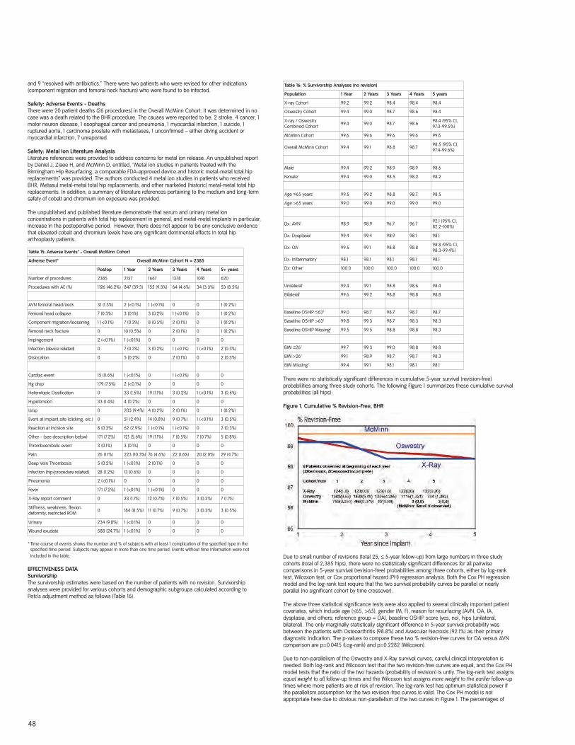
48
and 9 “resolved with antibiotics.” There were two patients who were revised for other indications(component migration and femoral neck fracture) who were found to be infected.
Safety: Adverse Events - DeathsThere were 20 patient deaths (26 procedures) in the Overall McMinn Cohort. It was determined in nocase was a death related to the BHR procedure. The causes were reported to be: 2 stroke, 4 cancer, 1motor neuron disease, 1 esophageal cancer and pneumonia, 1 myocardial infarction, 1 suicide, 1ruptured aorta, 1 carcinoma prostate with metastases, 1 unconfirmed – either diving accident ormyocardial infarction, 7 unreported.
Safety: Metal Ion Literature AnalysisLiterature references were provided to address concerns for metal ion release. An unpublished reportby Daniel J, Ziaee H, and McMinn D, entitled, “Metal ion studies in patients treated with theBirmingham Hip Resurfacing, a comparable FDA-approved device and historic metal-metal total hipreplacements” was provided. The authors conducted 4 metal ion studies in patients who receivedBHR, Metasul metal-metal total hip replacements, and other marketed (historic) metal-metal total hipreplacements. In addition, a summary of literature references pertaining to the medium and long-termsafety of cobalt and chromium ion exposure was provided.
The unpublished and published literature demonstrate that serum and urinary metal ionconcentrations in patients with total hip replacement in general, and metal-metal implants in particular,increase in the postoperative period. However, there does not appear to be any conclusive evidencethat elevated cobalt and chromium levels have any significant detrimental effects in total hiparthroplasty patients.
* Time course of events shows the number and % of subjects with at least 1 complication of the specified type in thespecified time period. Subjects may appear in more than one time period. Events without time information were notincluded in the table.
EFFECTIVENESS DATASurvivorshipThe survivorship estimates were based on the number of patients with no revision. Survivorshipanalyses were provided for various cohorts and demographic subgroups calculated according toPeto’s adjustment method as follows (Table 16).
There were no statistically significant differences in cumulative 5-year survival (revision-free)probabilities among three study cohorts. The following Figure 1 summarizes these cumulative survivalprobabilities (all hips):
Figure 1. Cumulative % Revision-Free, BHR
Due to small number of revisions (total 25, ≤ 5-year follow-up) from large numbers in three studycohorts (total of 2,385 hips), there were no statistically significant differences for all pairwisecomparisons in 5-year survival (revision-free) probabilities among three cohorts, either by log-ranktest, Wilcoxon test, or Cox proportional hazard (PH) regression analysis. Both the Cox PH regressionmodel and the log-rank test require that the two survival probability curves be parallel or nearlyparallel (no significant cohort by time crossover).
The above three statistical significance tests were also applied to several clinically important patientcovariates, which include age (≤65, >65), gender (M, F), reason for resurfacing (AVN, OA, IA,dysplasia, and others; reference group = OA), baseline OSHIP score (yes, no), hips (unilateral,bilateral). The only marginally statistically significant difference in 5-year survival probability wasbetween the patients with Osteoarthritis (98.8%) and Avascular Necrosis (92.1%) as their primarydiagnostic indication. The p-values to compare these two % revision-free curves for OA versus AVNcomparison are p=0.0415 (Log-rank) and p=0.2282 (Wilcoxon).
Due to non-parallelism of the Oswestry and X-Ray survival curves, careful clinical interpretation isneeded. Both log-rank and Wilcoxon test that the two revision-free curves are equal, and the Cox PHmodel tests that the ratio of the two hazards (probability of revision) is unity. The log-rank test assignsequal weight to all follow-up times and the Wilcoxon test assigns more weight to the earlier follow-uptimes where more patients are at risk of revision. The log-rank test has optimum statistical power ifthe parallelism assumption for the two revision-free curves is valid. The Cox PH model is notappropriate here due to obvious non-parallelism of the two curves in Figure 1. The percentages of
Table 15: Adverse Events* - Overall McMinn Cohort
Adverse Event* Overall McMinn Cohort N = 2385
Postop 1 Year 2 Years 3 Years 4 Years 5+ years
Number of procedures 2385 2157 1667 1378 1018 620
Procedures with AE (%) 1126 (46.2%) 847 (39.3) 155 (9.3%) 64 (4.6%) 34 (3.3%) 53 (8.5%)
AVN femoral head/neck 31 (1.3%) 2 (<0.1%) 1 (<0.1%) 0 0 1 (0.2%)
Femoral head collapse 7 (0.3%) 3 (0.1%) 3 (0.2%) 1 (<0.1%) 0 1 (0.2%)
Component migration/loosening 1 (<0.1%) 7 (0.3%) 8 (0.5%) 2 (0.1%) 0 1 (0.2%)
Femoral neck fracture 0 10 (0.5%) 0 2 (0.1%) 0 1 (0.2%)
Impingement 2 (<0.1%) 1 (<0.1%) 0 0 0 0
Infection (device related) 0 7 (0.3%) 3 (0.2%) 1 (<0.1%) 1 (<0.1%) 2 (0.3%)
Dislocation 0 5 (0.2%) 0 2 (0.1%) 0 2 (0.3%)
Cardiac event 15 (0.6%) 1 (<0.1%) 0 1 (<0.1%) 0 0
Hg drop 179 (7.5%) 2 (<0.1%) 0 0 0 0
Heterotopic Ossification 0 33 (1.5%) 19 (1.1%) 3 (0.2%) 1 (<0.1%) 3 (0.5%)
Hypotension 33 (1.4%) 4 (0.2%) 0 0 0 0
Limp 0 203 (9.4%) 4 (0.2%) 2 (0.1%) 0 1 (0.2%)
Event at implant site (clicking, etc.) 0 51 (2.4%) 14 (0.8%) 9 (0.7%) 1 (<0.1%) 3 (0.5%)
Reaction at incision site 8 (0.3%) 62 (2.9%) 1 (<0.1%) 1 (<0.1%) 0 2 (0.3%)
Other - (see description below) 171 (7.2%) 121 (5.6%) 19 (1.1%) 7 (0.5%) 7 (0.7%) 5 (0.8%)
Thromboembolic event 3 (0.1%) 3 (0.1%) 0 0 0 0
Pain 26 (1.1%) 223 (10.3%) 76 (4.6%) 22 (1.6%) 20 (2.0%) 29 (4.7%)
Deep Vein Thrombosis 5 (0.2%) 1 (<0.1%) 2 (0.1%) 0 0 0
Infection (hip/procedure related) 28 (1.2%) 13 (0.6%) 0 0 0 0
Pneumonia 2 (<0.1%) 0 0 0 0 0
Fever 171 (7.2%) 1 (<0.1%) 1 (<0.1%) 0 0 0
X-Ray report comment 0 23 (1.1%) 12 (0.7%) 7 (0.5%) 3 (0.3%) 7 (1.1%)
Stiffness, weakness, flexion deformity, restricted ROM 0 184 (8.5%) 11 (0.7%) 9 (0.7%) 3 (0.3%) 3 (0.5%)
Urinary 234 (9.8%) 1 (<0.1%) 0 0 0 0
Wound exudate 588 (24.7%) 1 (<0.1%) 0 0 0 0
Table 16: % Survivorship Analyses (no revision)
Population 1 Year 2 Years 3 Years 4 Years 5 years
X-ray Cohort 99.2 99.2 98.4 98.4 98.4
Oswestry Cohort 99.4 99.0 98.7 98.6 98.4
X-ray / Oswestry Combined Cohort 99.4 99.0 98.7 98.6 98.4 (95% CI,
97.3-99.5%)
McMinn Cohort 99.6 99.6 99.6 99.6 99.6
Overall McMinn Cohort 99.4 99.1 98.8 98.7 98.5 (95% CI,97.4-99.6%)
Male1 99.4 99.2 98.9 98.9 98.6
Female1 99.4 99.0 98.5 98.2 98.2
Age <65 years1 99.5 99.2 98.8 98.7 98.5
Age >65 years1 99.0 99.0 99.0 99.0 99.0
Dx: AVN1 98.9 98.9 96.7 96.7 92.1 (95% CI,82.2-100%)
Dx: Dysplasia1 99.4 99.4 98.9 98.1 98.1
Dx: OA1 99.5 99.1 98.8 98.8 98.8 (95% CI,98.3-99.4%)
Dx: Inflammatory1 98.1 98.1 98.1 98.1 98.1
Dx: Other1 100.0 100.0 100.0 100.0 100.0
Unilateral1 99.4 99.1 98.8 98.6 98.4
Bilateral1 99.6 99.2 98.8 98.8 98.8
Baseline OSHIP <632 99.0 98.7 98.7 98.7 98.7
Baseline OSHIP >632 99.8 99.3 98.7 98.3 98.3
Baseline OSHIP Missing2 99.5 99.5 98.8 98.8 98.3
BMI <262 99.7 99.3 99.0 98.8 98.8
BMI >262 99.1 98.9 98.7 98.7 98.3
BMI Missing2 99.4 99.1 98.1 98.1 98.1
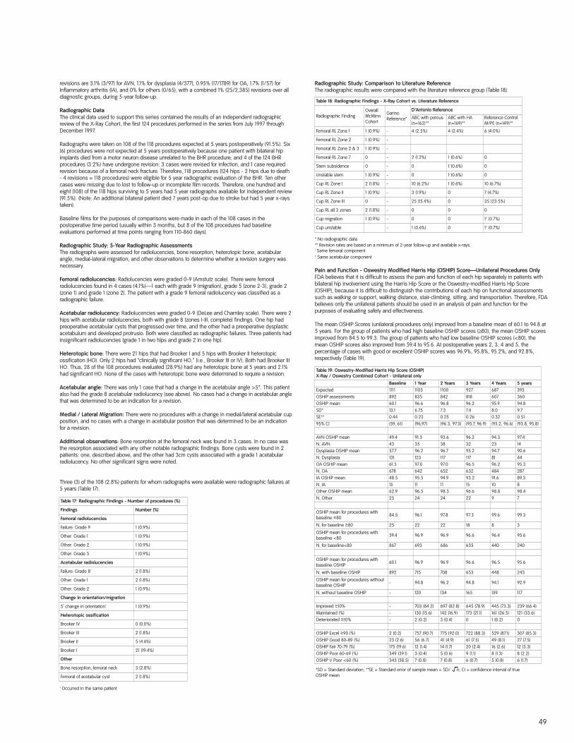
revisions are 3.1% (3/97) for AVN, 1.1% for dysplasia (4/377), 0.95% (17/1789) for OA, 1.7% (1/57) forInflammatory arthritis (IA), and 0% for others (0/65), with a combined 1% (25/2,385) revisions over alldiagnostic groups, during 5-year follow-up.
Radiographic DataThe clinical data used to support this series contained the results of an independent radiographicreview of the X-Ray Cohort, the first 124 procedures performed in the series from July 1997 throughDecember 1997.
Radiographs were taken on 108 of the 118 procedures expected at 5 years postoperatively (91.5%). Six(6) procedures were not expected at 5 years postoperatively because one patient with bilateral hipimplants died from a motor neuron disease unrelated to the BHR procedure; and 4 of the 124 BHRprocedures (3.2%) have undergone revision: 3 cases were revised for infection, and 1 case requiredrevision because of a femoral neck fracture. Therefore, 118 procedures (124 hips - 2 hips due to death- 4 revisions = 118 procedures) were eligible for 5 year radiographic evaluation of the BHR. Ten othercases were missing due to lost to follow-up or incomplete film records. Therefore, one hundred andeight (108) of the 118 hips surviving to 5 years had 5 year radiographs available for independent review(91.5%). (Note: An additional bilateral patient died 7 years post-op due to stroke but had 5 year x-raystaken).
Baseline films for the purposes of comparisons were made in each of the 108 cases in thepostoperative time period (usually within 3 months, but 8 of the 108 procedures had baselineevaluations performed at time points ranging from 110-860 days).
Radiographic Study: 5-Year Radiographic AssessmentsThe radiographs were assessed for radiolucencies, bone resorption, heterotopic bone, acetabularangle, medial-lateral migration, and other observations to determine whether a revision surgery wasnecessary.
Femoral radiolucencies: Radiolucencies were graded 0-9 (Amstutz scale). There were femoralradiolucencies found in 4 cases (4.1%)—1 each with grade 9 (migration), grade 5 (zone 2-3), grade 2(zone 1) and grade 1 (zone 2). The patient with a grade 9 femoral radiolucency was classified as aradiographic failure.
Acetabular radiolucency: Radiolucencies were graded 0-9 (DeLee and Charnley scale). There were 2hips with acetabular radiolucencies, both with grade 8 (zones I-III, complete) findings. One hip hadpreoperative acetabular cysts that progressed over time, and the other had a preoperative dysplasticacetabulum and developed protrusio. Both were classified as radiographic failures. Three patients hadinsignificant radiolucencies (grade 1 in two hips and grade 2 in one hip).
Heterotopic bone: There were 21 hips that had Brooker I and 5 hips with Brooker II heterotopicossification (HO). Only 2 hips had “clinically significant HO,” (i.e., Brooker III or IV). Both had Brooker IIIHO. Thus, 28 of the 108 procedures evaluated (28.9%) had any heterotopic bone at 5 years and 2.1%had significant HO. None of the cases with heterotopic bone were determined to require a revision.
Acetabular angle: There was only 1 case that had a change in the acetabular angle >5°. This patientalso had the grade 8 acetabular radiolucency (see above). No cases had a change in acetabular anglethat was determined to be an indication for a revision.
Medial / Lateral Migration: There were no procedures with a change in medial/lateral acetabular cupposition, and no cases with a change in acetabular position that was determined to be an indicationfor a revision.
Additional observations: Bone resorption at the femoral neck was found in 3 cases. In no case wasthe resorption associated with any other notable radiographic findings. Bone cysts were found in 2patients: one, described above, and the other had 3cm cysts associated with a grade 1 acetabularradiolucency. No other significant signs were noted.
Three (3) of the 108 (2.8%) patients for whom radiographs were available were radiographic failures at5 years (Table 17).
1 Occurred in the same patient
Radiographic Study: Comparison to Literature ReferenceThe radiographic results were compared with the literature reference group (Table 18).
* No radiographic data.** Revision rates are based on a minimum of 2-year follow-up and available x-rays.1 Same femoral component2 Same acetabular component
Pain and Function - Oswestry Modified Harris Hip (OSHIP) Score—Unilateral Procedures OnlyFDA believes that it is difficult to assess the pain and function of each hip separately in patients withbilateral hip involvement using the Harris Hip Score or the Oswestry-modified Harris Hip Score(OSHIP), because it is difficult to distinguish the contributions of each hip on functional assessmentssuch as walking or support, walking distance, stair-climbing, sitting, and transportation. Therefore, FDAbelieves only the unilateral patients should be used in an analysis of pain and function for thepurposes of evaluating safety and effectiveness.
The mean OSHIP Scores (unilateral procedures only) improved from a baseline mean of 60.1 to 94.8 at5 years. For the group of patients who had high baseline OSHIP scores (≥80), the mean OSHIP scoresimproved from 84.5 to 99.3. The group of patients who had low baseline OSHIP scores (<80), themean OSHIP scores also improved from 59.4 to 95.6. At postoperative years 2, 3, 4 and 5, thepercentage of cases with good or excellent OSHIP scores was 96.9%, 95.8%, 95.2%, and 92.8%,respectively (Table 19).
Table 19: Oswestry-Modified Harris Hip Score (OSHIP)X-Ray / Oswestry Combined Cohort - Unilateral only
Baseline 1 Year 2 Years 3 Years 4 Years 5 yearsExpected 1111 1103 1100 927 687 395OSHIP assessments 892 835 842 818 607 360OSHIP mean 60.1 96.6 96.8 96.2 95.9 94.8SD* 13.1 6.75 7.3 7.4 8.0 9.7SE** 0.44 0.23 0.25 0.26 0.32 0.5195% CI (59, 61) (96,97) (96.3, 97.3) (95.7, 96.9) (95.2, 96.6) (93.8, 95.8)
AVN OSHIP mean 49.4 91.3 93.6 96.2 94.3 97.4N, AVN 43 35 38 32 23 14Dysplasia OSHIP mean 57.7 96.2 96.7 95.2 94.7 90.6N, Dysplasia 131 123 117 117 81 44OA OSHIP mean 61.5 97.0 97.0 96.5 96.2 95.3N, OA 678 642 652 632 484 287IA OSHIP mean 48.5 95.5 94.9 93.2 91.6 89.3N, IA 15 11 11 15 10 8Other OSHIP mean 62.9 96.5 98.3 96.6 98.8 98.4N, Other 25 24 24 22 9 7
OSHIP mean for procedures withbaseline >80 84.5 96.1 97.8 97.3 99.6 99.3
N, for baseline >80 25 22 22 18 8 3
OSHIP mean for procedures withbaseline <80 59.4 96.9 96.9 96.6 96.4 95.6
N, for baseline<80 867 693 686 635 440 240
OSHIP mean for procedures withbaseline OSHIP 60.1 96.9 96.9 96.6 96.5 95.6
N, with baseline OSHIP 892 715 708 653 448 243
OSHIP mean for procedures withoutbaseline OSHIP - 94.8 96.2 94.8 94.1 92.9
N, without baseline OSHIP - 120 134 165 159 117
Improved >10% - 703 (84.2) 697 (82.8) 645 (78.9) 445 (73.3) 239 (66.4)Maintained (%) - 130 (15.6) 142 (16.9) 173 (21.1) 161 (26.5) 121 (33.6)Deteriorated >10% - 2 (0.2) 3 (0.4) 0 1 (0.2) 0
OSHIP Excel >90 (%) 2 (0.2) 757 (90.7) 775 (92.0) 722 (88.3) 529 (87.1) 307 (85.3)OSHIP Good 80-89 (%) 23 (2.6) 56 (6.7) 41 (4.9) 61 (7.5) 49 (8.1) 27 (7.5)OSHIP Fair 70-79 (%) 175 (19.6) 12 (1.4) 14 (1.7) 20 (2.4) 16 (2.6) 12 (3.3)OSHIP Poor 60-69 (%) 349 (39.1) 3 (0.4) 5 (0.6) 9 (1.1) 8 (1.3) 8 (2.2)OSHIP V Poor <60 (%) 343 (38.5) 7 (0.8) 7 (0.8) 6 (0.7) 5 (0.8) 6 (1.7)
49
Table 17: Radiographic Findings - Number of procedures (%)
Findings Number (%)
Femoral radiolucencies
Failure: Grade 9 1 (0.9%)
Other: Grade 1 1 (0.9%)
Other: Grade 2 1 (0.9%)
Other: Grade 5 1 (0.9%)
Acetabular radiolucencies
Failure: Grade 81 2 (1.8%)
Other: Grade 1 2 (1.8%)
Other: Grade 2 1 (0.9%)
Change in orientation/migration
5˚ change in orientation1 1 (0.9%)
Heterotopic ossification
Brooker IV 0 (0.0%)
Brooker III 2 (1.8%)
Brooker II 5 (4.6%)
Brooker I 21 (19.4%)
Other
Bone resorption, femoral neck 3 (2.8%)
Femoral of acetabular cyst 2 (1.8%)
Table 18: Radiographic Findings - X-Ray Cohort vs. Literature Reference
Radiographic FindingOverallMcMinnCohort
GarinoReference*
D’Antonio Reference
ABC with porous(n=162)**
ABC with HA (n=169)**
Reference ControlM/PE (n=149)**
Femoral RL Zone 1 1 (0.9%) - 4 (2.5%) 4 (2.4%) 6 (4.0%)
Femoral RL Zone 2 1 (0.9%) -
Femoral RL Zone 2 & 3 1 (0.9%) -
Femoral RL Zone 7 0 - 2 (1.2%) 1 (0.6%) 0
Stem subsidence 0 - 0 11 (0.6%) 0
Unstable stem 1 (0.9%) - 0 11 (0.6%) 0
Cup RL Zone I 2 (1.8%) - 10 (6.2%) 1 (0.6%) 10 (6.7%)
Cup RL Zone II 1 (0.9%) - 3 (1.9%) 0 7 (4.7%)
Cup RL Zone III 0 - 25 (15.4%) 0 35 (23.5%)
Cup RL all 3 zones 2 (1.8%) - 0 0 0
Cup migration 1 (0.9%) - 0 0 12 (0.7%)
Cup unstable - 1 (0.6%) 0 12 (0.7%)
*SD = Standard deviation; **SE = Standard error of sample mean = SD/ n; CI = confidence interval of trueOSHIP mean
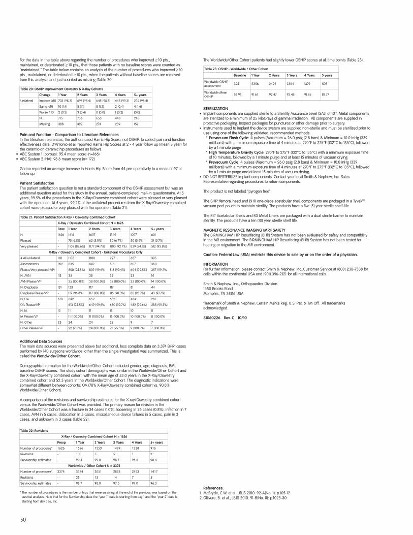
50
For the data in the table above regarding the number of procedures who improved ≥ 10 pts.,maintained, or deteriorated ≥ 10 pts., that those patients with no baseline scores were counted as“maintained.” The table below contains an analysis of the number of procedures who improved ≥ 10pts., maintained, or deteriorated ≥ 10 pts., when the patients without baseline scores are removedfrom this analysis and just counted as missing (Table 20).
Pain and Function - Comparison to Literature ReferencesIn the literature references, the authors used Harris Hip Score, not OSHIP, to collect pain and functioneffectiveness data. D’Antonio et al. reported Harris Hip Scores at 2 - 4 year follow up (mean 3 year) forthe ceramic-on-ceramic hip procedures as follows:
∑ ABC System 1 (porous): 95.4 mean score (n=166)∑ ABC System 2 (HA): 96.6 mean score (n= 172)
Garino reported an average increase in Harris Hip Score from 44 pre-operatively to a mean of 97 atfollow up.
Patient SatisfactionThe patient satisfaction question is not a standard component of the OSHIP assessment but was anadditional question asked for this study in the annual, patient-completed, mail-in questionnaire. At 5years, 99.5% of the procedures in the X-Ray/Oswestry combined cohort were pleased or very pleasedwith the operation. At 5 years, 99.2% of the unilateral procedures from the X-Ray/Oswestry combinedcohort were pleased or very pleased with the operation (Table 21).
Additional Data SourcesThe main data sources were presented above but additional, less complete data on 3,374 BHR™ casesperformed by 140 surgeons worldwide (other than the single investigator) was summarized. This iscalled the Worldwide/Other Cohort.
Demographic information for the Worldwide/Other Cohort included gender, age, diagnosis, BMI,baseline OSHIP scores. The study cohort demography was similar in the Worldwide/Other Cohort andthe X-Ray/Oswestry combined cohort, with the mean age of 53.0 years in the X-Ray/Oswestrycombined cohort and 52.5 years in the Worldwide/Other Cohort. The diagnostic indications weresomewhat different between cohorts: OA (78% X-Ray/Oswestry combined cohort vs. 90.8%Worldwide/Other Cohort).
A comparison of the revisions and survivorship estimates for the X-ray/Oswestry combined cohortversus the Worldwide/Other Cohort was provided. The primary reason for revision in theWorldwide/Other Cohort was a fracture in 34 cases (1.0%), loosening in 26 cases (0.8%), infection in 7cases, AVN in 5 cases, dislocation in 5 cases, miscellaneous device failures in 5 cases, pain in 3cases, and unknown in 3 cases (Table 22).
* The number of procedures is the number of hips that were surviving at the end of the previous year based on thesurvival analysis. Note that for the Survivorship data the “year 1” data is starting from day 1 and the “year 2” data isstarting from day 366, etc.
The Worldwide/Other Cohort patients had slightly lower OSHIP scores at all time points (Table 23).
STERILIZATION∑ Implant components are supplied sterile to a Sterility Assurance Level (SAL) of 10-6. Metal components
are sterilized to a minimum of 25 kiloGrays of gamma irradiation. All components are supplied inprotective packaging. Inspect packages for punctures or other damage prior to surgery.
∑ Instruments used to implant the device system are supplied non-sterile and must be sterilized prior touse using one of the following validated, recommended methods:
* Prevacuum Flash Cycle: 4 pulses (Maximum = 26.0 psig (2.8 bars) & Minimum = 10.0 inHg (339millibars)) with a minimum exposure time of 4 minutes at 270°F to 275°F (132°C to 135°C), followedby a 1 minute purge
* High Temperature Gravity Cycle: 270°F to 275°F (132°C to 135°C) with a minimum exposure timeof 10 minutes, followed by a 1 minute purge and at least 15 minutes of vacuum drying.
* Prevacuum Cycle: 4 pulses (Maximum = 26.0 psig (2.8 bars) & Minimum = 10.0 inHg (339millibars)) with a minimum exposure time of 4 minutes at 270°F to 275°F (132°C to 135°C), followedby a 1 minute purge and at least 15 minutes of vacuum drying.
∑ DO NOT RESTERILIZE implant components. Contact your local Smith & Nephew, Inc. SalesRepresentative regarding procedures to return components.
The product is not labeled “pyrogen free”.
The BHR™ femoral head and BHR one-piece acetabular shell components are packaged in a TyvekTM
vacuum peel pouch to maintain sterility. The products have a five (5) year sterile shelf-life.
The R3™ Acetabular Shells and R3 Metal Liners are packaged with a dual sterile barrier to maintainsterility. The products have a ten (10) year sterile shelf life.
MAGNETIC RESONANCE IMAGING (MRI) SAFETY The BIRMINGHAM HIP Resurfacing (BHR) System has not been evaluated for safety and compatibilityin the MR environment. The BIRMINGHAM HIP Resurfacing (BHR) System has not been tested forheating or migration in the MR environment.
Caution: Federal Law (USA) restricts this device to sale by or on the order of a physician.
INFORMATIONFor further information, please contact Smith & Nephew, Inc.,Customer Service at (800) 238-7538 forcalls within the continental USA and (901) 396-2121 for all international calls.
Smith & Nephew, Inc., Orthopaedics Division1450 Brooks RoadMemphis, TN 38116 USA
™Trademark of Smith & Nephew, Certain Marks Reg. U.S. Pat. & TM Off. All trademarksacknowledged.
81060226 Rev. C 10/10
References:1. McBryde, C.W. et al., JBJS 2010. 92-A(No. 1): p.105-122. Ollivere, B. et al., JBJS 2010. 91-B(No. 8): p.1025-30
Table 20: OSHIP Improvement Oswestry & X-Ray Cohorts
Change 1 Year 2 Years 3 Years 4 Years 5+ years
Unilateral Improve >10 703 (98.3) 697 (98.4) 645 (98.8) 445 (99.3) 239 (98.4)
Same <10 10 (1.4) 8 (1.1) 8 (1.2) 2 (0.4) 4 (1.6)
Worse >10 2 (0.3) 3 (0.4) 0 (0.0) 1 (0.2) (0.0)
N 715 708 653 448 243
Missing 388 392 274 239 152
Table 21: Patient Satisfaction X-Ray / Oswestry Combined Cohort
X-Ray / Oswestry Combined Cohort N = 1626
Base 1 Year 2 Years 3 Years 4 Years 5+ years
N 1626 1616 1607 1349 1007 601
Pleased - 75 (6.1%) 62 (5.0%) 80 (6.7%) 50 (5.6%) 31 (5.7%)
Very pleased - 1109 (89.6%) 1177 (94.7%) 1100 (92.7%) 839 (94.1%) 512 (93.8%)
X-Ray / Oswestry Combined Cohort - Unilateral Procedures Only
# All unilateral 1111 1103 1100 927 687 395
Assessments 892 835 842 818 607 360
Please/Very pleased (VP) - 800 (95.8%) 839 (99.6%) 813 (99.4%) 604 (99.5%) 357 (99.2%)
N, AVN 43 35 38 32 23 14
AVN Please/VP - 35 (100.0%) 38 (100.0%) 32 (100.0%) 23 (100.0%) 14 (100.0%)
N, Dysplasia 131 123 117 117 81 44
Dysplasia Please/VP - 119 (96.8%) 117 (100.0%) 115 (98.3%) 80 (98.7%) 43 (97.7%)
N, OA 678 642 652 632 484 287
OA Please/VP - 613 (95.5%) 649 (99.6%) 630 (99.7%) 482 (99.6%) 285 (99.3%)
N, IA 15 11 11 15 10 8
IA Please/VP - 11 (100.0%) 11 (100.0%) 15 (100.0%) 10 (100.0%) 8 (100.0%)
N, Other 25 24 24 22 9 7
Other Please/VP - 22 (91.7%) 24 (100.0%) 21 (95.5%) 9 (100.0%) 7 (100.0%)
Table 23: OSHIP - Worldwide / Other Cohort
Baseline 1 Year 2 Years 3 Years 4 Years 5 years
Worldwide OSHIPassessment 395 2356 2492 2364 1379 505
Worldwide MeanOSHIP 56.95 91.67 92.47 92.45 91.86 89.77
Table 22: Revisions
X-Ray / Oswestry Combined Cohort N = 1626
Preop 1 Year 2 Years 3 Years 4 Years 5+ years
Number of procedures* 1626 1626 1553 1499 1238 916
Revisions - 10 5 5 1 3
Survivorship estimates - 99.4 99.0 98.7 98.6 98.4
Worldwide / Other Cohort N = 3374
Number of procedures* 3374 3374 3051 2888 2493 1417
Revisions - 35 15 14 7 5
Survivorship estimates - 98.7 98.0 97.5 97.0 96.3

51

OrthopedicsSmith & Nephew, Inc1450 Brooks RoadMemphis, TN 38116USA
Telephone: 901-396-2121Information: 1-800-821-5700Orders/inquiries: 1-800-238-7538
www.smith-nephew.com
10/10 REV A 4567-0103
™Trademark of Smith & Nephew, Reg. US Pat. & Tm. Off.