beyond design code, introduction of defect tolerance
TRANSCRIPT
Copyright 2015 of CGN – Proprietary and confidential information of CGN should not be disclosed and used without CGN’s prior approval.
April, 2019
1
Beyond Design Code, Introduction of
Defect Tolerance Assessment of UK HPR1000
Copyright 2015 of CGN – Proprietary and confidential information of CGN should not be disclosed and used without CGN’s prior approval.2
Comprehensive of terminology “structural integrity” in UK:
a) A much more wider range than China practice whereas mainly mechanical analysis isfocused in China practice.
b) No design codes & standards specified, and codes & standards are not enough.c) Demonstrated by “safety case”.
Besides design codes & standards, the UK HPR1000 also considers UK context. In terms ofstress and assessment, it is mainly called ‘Avoidance of Fracture’.
Copyright 2015 of CGN – Proprietary and confidential information of CGN should not be disclosed and used without CGN’s prior approval.3
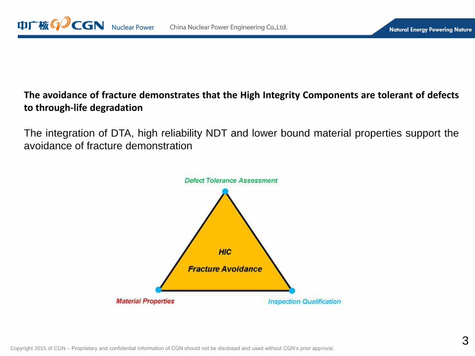
The avoidance of fracture demonstrates that the High Integrity Components are tolerant of defectsto through-life degradation
The integration of DTA, high reliability NDT and lower bound material properties support the
avoidance of fracture demonstration
Copyright 2015 of CGN – Proprietary and confidential information of CGN should not be disclosed and used without CGN’s prior approval.4
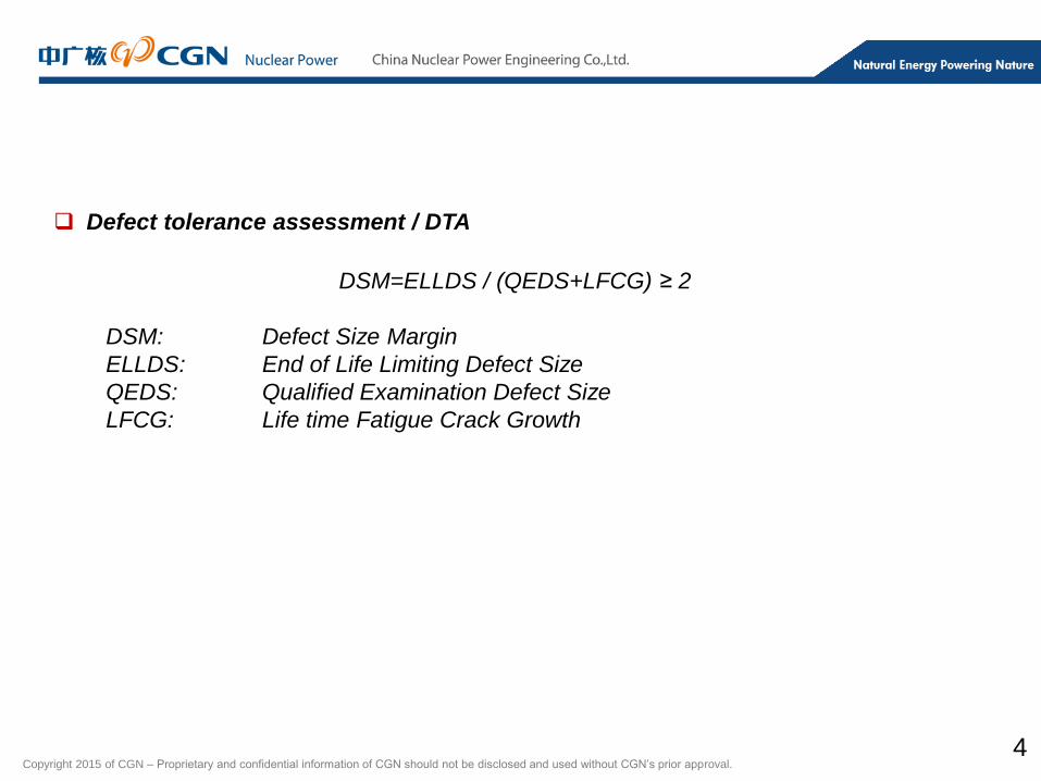
Defect tolerance assessment / DTA
DSM=ELLDS / (QEDS+LFCG) ≥ 2
DSM: Defect Size Margin
ELLDS: End of Life Limiting Defect Size
QEDS: Qualified Examination Defect Size
LFCG: Life time Fatigue Crack Growth
Copyright 2015 of CGN – Proprietary and confidential information of CGN should not be disclosed and used without CGN’s prior approval.5
DTA main Procedure is following:
1. Material property determination
2. Classify loadings and consequences stresses
3. Defect characterization
4. Analysis type selection (crack initiation or tearing )
5. Determine final defect size (crack fatigue crack growth)
6. Determine end of life limiting defect size
7. DSM target check and refinement
Copyright 2015 of CGN – Proprietary and confidential information of CGN should not be disclosed and used without CGN’s prior approval.6
Characteristic of DTA:
1. FAD diagram method, no safety factor inherent (R6 procedure)
2. Conservative material properties assumption
3. Conservative loads and loads combination
4. Residual stresses involved
Copyright 2015 of CGN – Proprietary and confidential information of CGN should not be disclosed and used without CGN’s prior approval.7
Loading
1. Steady load, dead weight, mechanical loads and thermal loads
2. Transients load, pressure, thermal and flow rate transients
3. Residual stresses
4. others
Stress and SIF
The stresses arising from loadings should be divided into primary stresses and
secondary stresses according to the contribution to plastic collapse. Due to the
interaction between primary and secondary stresses, a coefficient will be applied
to Stress Intensity Factor (SIF) caused by secondary stresses, and then
combined with SIF resulted by primary stresses.
Copyright 2015 of CGN – Proprietary and confidential information of CGN should not be disclosed and used without CGN’s prior approval.8
Defect Characterisation
For defect tolerance assessment in GDA, only surface planar flaws are assumed.
The flaw depth, width and shapes cause different stress intensity factor forms.
Analysis Type Selection
Crack initiation
Base analysis type for all conditions.
Crack tearing
Alternative analysis type for emergency and fault condition.

Copyright 2015 of CGN – Proprietary and confidential information of CGN should not be disclosed and used without CGN’s prior approval.9
Determine Final Defect Size
Fatigue Crack Propagation
Paris Law is introduced for fatigue crack growth.
da / dN=A(△K)m
Final defect size = initial crack size + fatigue crack growth
Copyright 2015 of CGN – Proprietary and confidential information of CGN should not be disclosed and used without CGN’s prior approval.10
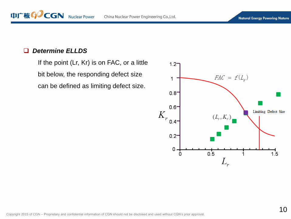
Determine ELLDS
If the point (Lr, Kr) is on FAC, or a little
bit below, the responding defect size
can be defined as limiting defect size.
Copyright 2015 of CGN – Proprietary and confidential information of CGN should not be disclosed and used without CGN’s prior approval.11
FAC Curves Selection
1. R6 offers three types of failure assessment curves, named option 1, 2
and 3.
2. For conservative purpose, it is prior to select option 1 for DTA. If option 1
is too conservative, option 2 and 3 are the candidate options.
3. Lr(max) could be determined as following approximately:
Lr(max) =( σy + σu ) / 2σy
Copyright 2015 of CGN – Proprietary and confidential information of CGN should not be disclosed and used without CGN’s prior approval.12
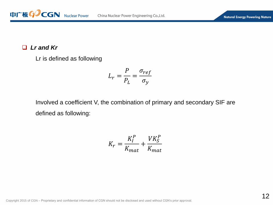
Lr and Kr
Lr is defined as following
Involved a coefficient V, the combination of primary and secondary SIF are
defined as following:
𝐿𝑟 =𝑃
𝑃𝐿=𝜎𝑟𝑒𝑓
𝜎𝑦
𝐾𝑟 =𝐾𝐼𝑃
𝐾𝑚𝑎𝑡+𝑉𝐾𝑆
𝑃
𝐾𝑚𝑎𝑡
Copyright 2015 of CGN – Proprietary and confidential information of CGN should not be disclosed and used without CGN’s prior approval.13
DSM Check
1. Amount of crack tearing instead of initiation in Level D
2. More realistic material property in some cases
3. Selection of more realistic FAC curve while in large Lr regime
4. Alternative methods
Copyright 2015 of CGN – Proprietary and confidential information of CGN should not be disclosed and used without CGN’s prior approval.
Thanks
14