best practice guide for rfid on metal tags - xerafy · rfid basics radio frequency identification...
TRANSCRIPT

Best Practice Guide for RFID on Metal Tags

Best Practices Topics Covered
• RFID Basics • Optimal Tag Orientation • XERAFY Tags Specifications • Problems with standard passive UHF RFID on Metal • Reading a Tag • Application Environment • Mounting on Metal Surface Prep • How to embed tags • RFID Mounting on Small Assets • RFID Mounting on Large Assets • RFID Mounting for Aerospace • RFID Mounting on IT Assets

RFID Basics
Radio Frequency Identification System • Tag consisting of IC attached to antenna that receives and back scatters
received RF signal • Interrogator (aka “Reader”) that generates encoded RF signals and feeds to
transmit antenna • Reader detects and interprets back scatter (reflected RF at same carrier
frequency as transmit signal which is modulated to transmit data) • Reader may be stand-alone (“fixed”) or a handheld
RFID Interrogator
Tx Rx
RF request signal
Backsca*er contains EPC & User Mem. Data

Material Physics
Material of any kind carries what is known as a DIELECTRIC CONSTANT. Essentially, this is the measure of a material’s ability to act as a capacitor.
Low dielectric materials generally do not reflect RF energy and thus do not reduce the performance of a RFID tag tuned for such a surface. Low dielectric materials (also known as “RF lucent”) include:
• Dry paper (Ɛr = 2) • Plastic (non-carbon) (Ɛr = 2) • Plate Glass (Ɛr= 5)
High dielectric materials tend to reflect more RFID energy and therefore detune a RFID tag tuned for low dielectric surfaces.
RF “opaque” materials either absorb or reflect RF signals • Metal (Ɛr = 11.5 iron & aluminum) • Carbide powder (Ɛr = 7.5) • Water (Ɛr = 80 at room temp., 55 near boiling temp) • “New” Wood – absorbs (Southern Pine and generally fresh cut wood contains moisture that hinders RF signal)

Optimal Tag Orientation
Electromagne;c radia;on pa*ern
OPTIMIZING TAG ORIENTATION yields maximum tag performance. For the NanoX II, a horizontal orientation will give best results with respect to a linearly polarized antenna.
Note the orientation of the NanoX II on the left is horizontal and lines up with the polarization of the handheld reader antenna.

Rugged X II Specifications PicoX II Nanox II Microx II
Dimension 0.70 x 0.43 x 0.19in (17.7 x 10.9 x 4.8mm)
1.25 x 0.51 x 0.19 in (31.7 x 12.9 x 4.8 mm)
2.01 x 1.43 x 0.30in (51 x 36.3 x 7.5mm)
Weight 2 g 5 g 29 g
Read Range on-metal 4W EIRP(2W ERP):6.6 ft (2 m)
4W EIRP(2W ERP):20 ft (6 m)
4W EIRP(2W ERP):33 ft (10 m)
Operating Temperature -22ºF to +185ºF (-30ºC to +85ºC)
-22ºF to +185ºF (-30ºC to +85ºC)
-22ºF to +185ºF (-30ºC to +85ºC)
Application Temperature -40ºF to +302ºF (-40ºC to +150ºC)
-40ºF to +302ºF (-40ºC to +150ºC)
-40ºF to +482ºF (-40ºC to +250ºC)
IP Rating IP68 IP68 IP68
Attachment High performance acrylic adhesive Rivet hole, 0.12 in(3.2mm); adhesive(optional)
Memory EPC Memory: 96 bits (extendible to 480 bits) User Memory: 512 bits total (8 blocks of 64 bits) TID: 64 bit unique
Standard EPC Global Gen 2 (US, EU, JP frequencies)
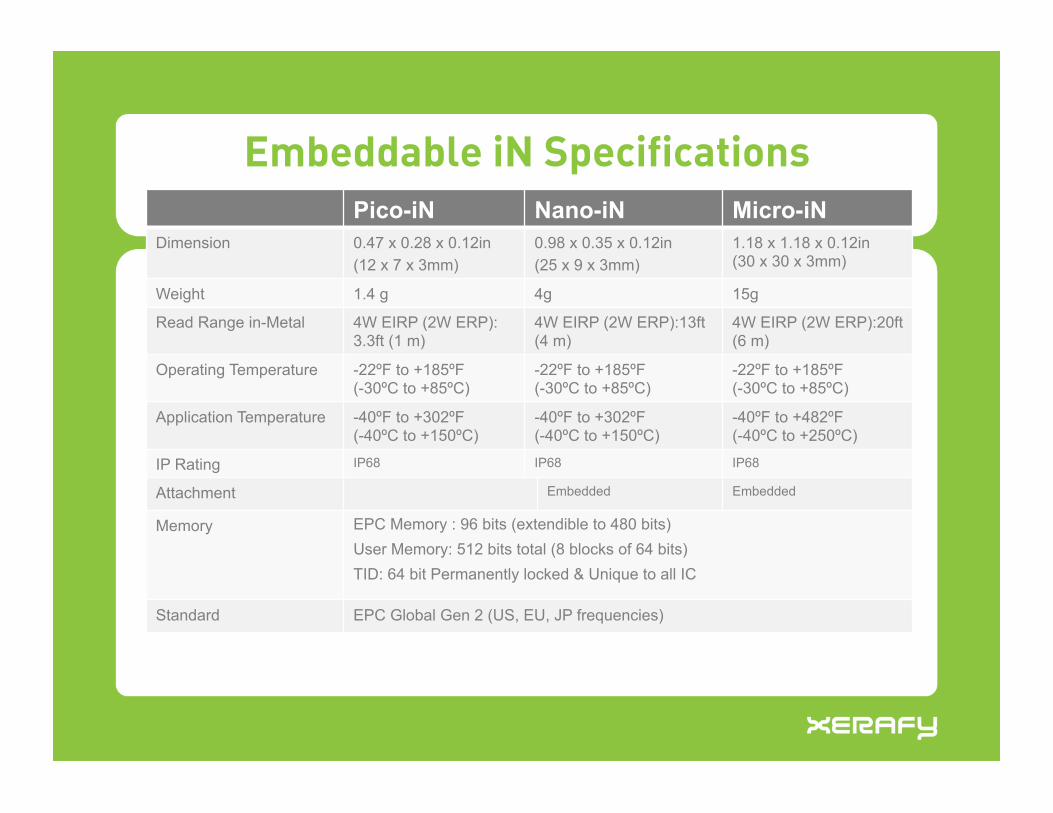
Pico-iN Nano-iN Micro-iN
Dimension 0.47 x 0.28 x 0.12in (12 x 7 x 3mm)
0.98 x 0.35 x 0.12in (25 x 9 x 3mm)
1.18 x 1.18 x 0.12in (30 x 30 x 3mm)
Weight 1.4 g 4g 15g
Read Range in-Metal 4W EIRP (2W ERP):3.3ft (1 m)
4W EIRP (2W ERP):13ft (4 m)
4W EIRP (2W ERP):20ft (6 m)
Operating Temperature -22ºF to +185ºF (-30ºC to +85ºC)
-22ºF to +185ºF (-30ºC to +85ºC)
-22ºF to +185ºF (-30ºC to +85ºC)
Application Temperature -40ºF to +302ºF (-40ºC to +150ºC)
-40ºF to +302ºF (-40ºC to +150ºC)
-40ºF to +482ºF (-40ºC to +250ºC)
IP Rating IP68 IP68! IP68!
Attachment Embedded! Embedded!
Memory EPC Memory : 96 bits (extendible to 480 bits) User Memory: 512 bits total (8 blocks of 64 bits) TID: 64 bit Permanently locked & Unique to all IC
Standard EPC Global Gen 2 (US, EU, JP frequencies)
Embeddable iN Specifications

Pico-On Plus Pico-iN Plus Picox II Plus
Dimension 0.47 x 0.28 x 0.12in (12 x 7 x 3mm)
0.47 x 0.28 x 0.12in (12 x 7 x 3mm)
0.70 x 0.43 x 0.19in (17.7 x 10.9 x 4.8mm)
Weight 1.4 g 1.4 g 2 g
Read Range on-metal 4W EIRP(2W ERP):10 ft (3 m)
4W EIRP(2W ERP):6.6 ft (2 m)
4W EIRP(2W ERP):10 ft (3 m)
Operating Temperature -22ºF to +185ºF (-30ºC to +85ºC)
-22ºF to +185ºF (-30ºC to +85ºC)
-22ºF to +185ºF (-30ºC to +85ºC)
Application Temperature -40ºF to +302ºF (-40ºC to +150ºC)
-40ºF to +302ºF (-40ºC to +150ºC)
-40ºF to +302ºF (-40ºC to +150ºC)
IP Rating IP68 IP68 IP68
Attachment High performance adhesive Embedded High performance adhesive
Memory EPC Memory : 96 bits (extendible to 480 bits) User Memory: 512 bits total (8 blocks of 64 bits) TID: 64 bit Permanently locked & Unique to all IC
Standard EPC Global Gen 2 (US, EU, JP frequencies)
Pico Plus Specifications

Data Trak Versa Trak Cargo Trak Global Trak Dimension 1.45 x 0.51 x 0.12in
(36.7 x 13 x 3mm) 1.97 x 0.67 x 0.20in (50 x 17 x 5mm)
3.94 x 1.02 x 0.35in (100 x 26 x 8.9mm)
1.50 x 0.51 x 0.15 in (38 x 13 x 3.8 mm)
Weight 2 g 3g 21 g 2.6 g
Read Range on-metal
4W EIRP(2W ERP):13 ft (4 m)
4W EIRP(2W ERP):26 ft (8 m)
4W EIRP(2W ERP):39 ft (12 m) Up to 8 ft (2.5 m)
Read Range off-metal
4W EIRP(2W ERP):6.6 ft (2m)
4W EIRP(2W ERP):13 ft (4 m)
4W EIRP(2W ERP):20 ft (6 m)
Up to 6 ft (1.8 m)
Operating Temperature
-22ºF to +185ºF (-30ºC to +85ºC)
-22ºF to +185ºF (-30ºC to +85ºC)
-40ºF to +185ºF (-40ºC to +85ºC)
Application Temperature
-22ºF to +185ºF (-30ºC to +85ºC)
-22ºF to +185ºF (-30ºC to +85ºC)
-40ºF to +185ºF (-40ºC to +85ºC)
-22ºF (-30ºC) to +185ºF (+85ºC)
IP Rating IP54 IP54 IP68 IP54
Attachment High performance adhesive ; Hang clip(optional)
High performance adhesive
Rivet hole,0.14 in(3.5mm); adhesive(optional)
High performance adhesive; tether
Memory EPC Memory : 96 bits (extendible to 480 bits) User Memory: 512 bits total (8 blocks of 64 bits)
Standard EPC Global Gen 2 (US, EU frequencies)
EPC Global Gen 2 (US, EU frequencies)
EPC Global Gen 2 (US, EU frequencies)
EPC Global Gen 2 (Global frequency)
Versatile Trak Specifications

Nano-iN XL Nano XL Sky ID
Dimension 1.02 x 0.35 x 0.12in (26 x 9 x 3mm)
1.25 x 0.51 x 0.19in (31.7 x 12.9 x 4.8mm)
1.38 x 0.79 x 0.16in (35 x 20 x 4.1mm)
Weight 3.5 g 5 g 6g
Read Range 4W EIRP (2W ERP):2.6 ft (0.8 m) 2W EIRP US(1W EIRP EU): 2ft (0.6m)
4W EIRP (2W ERP):4 ft (1.2 m) 2W EIRP US(1W EIRP EU): 2.6 ft (0.8m)
4W EIRP (2W ERP):6ft (1.8 m) 2W EIRP US(1W EIRP EU): 2.6 ft (0.8m)
Operating Temperature +32ºF to +185ºF (0ºC to +70ºC)
+32ºF to +185ºF (0ºC to +70ºC)
+32ºF to +185ºF (0ºC to +70ºC)
Application Temperature -40ºF to +302ºF (-40ºC to +150ºC)
-40ºF to +302ºF (-40ºC to +150ºC)
-40ºF to +257ºF (-40ºC to +125ºC)
IP Rating IP68 IP68 IP68
Attachment Embedded High performance adhesive
High performance adhesive
Memory EPC Memory : 32 bytes User Memory: 4k byte or 8k byte
Standard EPC Global Gen 2 (US, EU frequencies)
EPC Global Gen 2 (US, EU frequencies)
EPC Global Gen 2 (Global frequency)
High Memory XL Specifications

Why do UHF RFID passive tags not always work on metal?
Generally speaking, passive UHF tags are tuned for mounting and use on dielectric material (non-conductive) such as cardboard, non-carbon plastic and general non-metallic surfaces typical in the supply chain industry.
When used on or in proximity of a metal or metallic dielectric equivalent surface a passive tag will act in one of 3 ways:
• Conducting surface: Placing a dipole RFID tag flush on a metal surface creates an effective electrical “short”
• Interferer: Certain distances between a metal surface and dipole RFID tag cause a backscattered signal to scramble rather than reflect (see next item)
• Reinforcer: If the spacing is just right (around ¼” for UHF 915 MHz between tag and metal surface), tag will properly backscatter
Conventional tag spaced from metal creating interference of backscatter Conventional tag spaced around ¼” from
metal & functions well. BUT, this is impractical for real life applications

Xerafy Read-on or Embed-in-Metal Tags
Tags mounted on spacers, however, can be vulnerable to physical damage and may not be convenient nor realistic on a large scale deployment
Xerafy tags have a patented antenna design that are tuned to work properly directly on, or even embedded in, metal surfaces without bulky spacers.
Xerafy tag fully functioning mounted directly to metal
Xerafy tag fully functioning embedded in metal

Reading a Tag
When mounting or reading a RFID tag, take into consideration the trajectory of the RF signal with respect to tag location. Examples:
Correct: RF signal and
backscatter is not obstructed by metal
Wrong: RF signal and backscatter is
obstructed by metal
MicroX II

Eliminating False Reads
False or “phantom” reads are errors in data collection that can be false “positive” when a tag’s signal is captured that is outside the portal or false “negative” when the system fails to record a tag’s signal.
False Positive Read Correction False positive readings could be a result of the reader's detection field being spread wider than necessary so that signals from tags farther than its intended scope are captured. • Adjust reader output power (Transmit) • Every 6dB of power reduction reduces power output by half and also reduces RF spread
False Negative Read Correction False negative readings could be a result of metal shielding or RF waves causing signal interference or due to collisions that occur when a reader attempts to simultaneously read multiple tags. • Utilize systems with data filtering that can account for latent tag reads. • Use carbon, ferrite or mesh grid shielding or any material that absorbs RF signals is suitable as RF “shielding”.
Duplicate Read Correction
• Duplicate reads occur when tags remain in the reader's detection field longer than software filter settings
• Check if tags are simultaneously present in the field of multiple readers.
30 dBM Tx Pwr
23 dBM Tx Pwr

Application Environment
Temperature The read rate and lifetime of the tag will depend on the temperature conditions. Cold temperatures below specification may slow read rates. High temperatures can cause erratic performance.
RF Signal Interference Determining if other RF signals are in application environment using spectrum analyzer.
• If RF rich environment use DRM/Miller=4 Encoding on reader • RF Interference may be caused by older wireless infrastructures
operating at 915 MHz. Most modern Wi-Fi systems are 2.45-5 GHz and do not cause issues.
• Forklift and WIP tracking systems are typically sub-900 MHz and fixed frequency)

Mounting on Metal Surface Prep
For maximum adhesion, the following steps should be taken:
1. Clean surface using Isopropyl alcohol, alcohol pad or equivalent solvent ensuring surface is free from dirt, dust, oil and misc. debris that may affect adhesion
2. Handle tag by edges, peel release liner from back ensuring not to touch adhesive
3. Place tag in desired tagging location and firmly apply even pressure to tag for 5 seconds
4. Do not disturb newly mounted tag for at least 15 minutes to ensure proper adhesive seating

How to Embed –iN Tags
Step 1 Prepare the cavity according to specifications for iN Tags. A circular cut cavity is optimal for signal range.
Step 4 Fill in socket with resin that does not contain any metallic ingredients
Step 5 Make sure to fill any gaps between tag and socket wall
Step 6 Allow resin to cure and tag is ready for use.
Step 2 Apply epoxy to bottom of tag. Step 3 Position tag in center of socket. Ensure a flat metallic surface is used to eliminate gaps from the tag to the metal surface.

Mounting Tags on Small Assets
Tool Tracking • The Xerafy PicoX II and NanoX II tag are best for tracking small objects and can be mounted directly onto tool. • Select permanent adhesive for security applications. • iN Series can be embedded inside tools for maximum security and utilization at pre or post manufacturer.
Firearms • The XERAFY Pico-iN Plus can be embedded or inserted into the revolver handle or rifle base • The RFID tag UID number can not be duplicated or replaced for optimal security and traceability
Equipment MRO and work-in progress • Valves, flanges and equipment requiring permanent identification in rugged environments can use the X series tags or embedded metal labels.
• The XERAFY tags can survive the high temperature and pressure of autoclaves.
• Tags are typically attached to aluminum fixtures for fabricating subassemblies.

Mounting Tags on Large Assets
Gas Cylinder • Microx II tag is most rugged and provides long read range optimal for cylinder tracking. • Place the Xerafy Microx II tag is affixed to a metal surface on the vehicle. • Optimal performance when tag is aligned within line of sight of the reader. • Consider extreme temperatures of the object does impact read performance of tag. • Microx II tag can be placed inside the vehicle and send signals through glass. Windows with defrosters or metallic
Cargo Containers
• Freight carriers generally use more than one tag programmed with the same EPC number on opposite corners of the container to ensure data capture in any orientation through the read portal.
• Tags should be placed facing the reader antenna to ensure maximum tag antenna surface area is exposed to RF.
• The tags may be read “on edge” but range and general sensitivity will be much less.

Mounting Tags on Aerospace parts
Flyable Part Tracking • Sky-ID tag is most rugged high memory RFID tag that is SAE AS5678 certified for flyable parts. • Sky-ID can be affixed to a metal plate for human identifiable part markings. • Supplier should create the 476 bit ATA Spec 2000 birth records including:
• Manufacturer CAGE Code (MFR) • Serial Number (SER) • Original Part Number (PNO) • UID Construct Number (UIC) • Part Description (PDT) • Manufacture Date (DMF) • International Commodity Code (ICC]
High memory includes additional user memory for maintenance records and archival records that can’t be modified.
Spare Parts
• Configuration Management can be improved through tracking assembly and sub-assembly revision levels from receipt through in-use products.
• Create an audit trail by attaching XL series and programming traceable component records of Serial #, Lot #, Batch #, etc
• Set up inspection-triggering function for durable parts and tooling to maintain calibration, usage cycle-count, replacement, or maintenance.
• Scanning inventory and in-use parts with handheld reader provides fast and accurate identification of old revision parts due for replacement or upgrade.

Mounting Tags on IT Assets
Laptops • Place on side of laptop out of normal path of use. Do not place underneath laptop where it may get knocked off and also make laptop uneven on surface.
• Select a surface where there is direct metal contact on the whole tag.
• Place on lid of laptop alongside GIS asset sticker or company asset identification label
• For security systems, use reader portals on entryway and exits that prevent laptop theft.
• For IT asset management use a handheld reader to scan office or check-in/check-out policies.
Blade and Rack Servers • Place tag on plastic fascia away from surrounding metal, ventilation slots, and removable surfaces; such as access panels and hard drives.
• Place on edge of chassis, free of screws and mounting hardware or where it may get knocked off.
• Position the tag for optimal orientation to the type of reader antenna used and inline with the most free metal area.
• Systems for medium level security and room level IT asset inventory management may use portable reader cart with fixed reader and antennas on cart pushed up and down aisle for blade server inventory.
• System for inventory management can use a handheld reader to routinely scan installed blades for inventory.

For product or technology inquiries email: [email protected]
XERAFY Headquarters Unit 3709 Lippo Center Tower II 89 Queensway ,Admiralty, Hong Kong Phone: +852 3665 7232 Fax: +852 3665 7288
XERAFY Sales & Marketing 3102 Maple Ave Suite 450 Dallas, TX 75201 Phone: +1 214 800 2339 Fax: +1 817 284 1766
XERAFY Sales 911 Beacon Square Court #441 Gaithersburg, MD 20878 Phone: +1 301 641-7408
XERAFY 641 Tianshan Rd. Building 3, Suite 512 Shanghai 200336 Phone: +86 21 62060668 Fax: +86 21 62060662