best practice brochure: co- firing of biomass (main...
TRANSCRIPT

Best Practice Brochure: Co-Firing of Biomass (Main Report) Report No. COAL R287 DTI/Pub URN 05/1160 May 2005

ii
The DTI drives our ambition of ‘prosperity for all’ by working to create the best environment for business success in the UK. We help people and companies become more productive by promoting enterprise, innovation and creativity.
We champion UK business at home and abroad. We invest heavily in world-class science and technology. We protect the rights of working people and consumers. And we stand up for fair and open markets in the UK, Europe and the world.

iii
by Mike Colechin E.ON UK – Power Technology Ratcliffe-on-Soar Nottingham NG11 0EE Tel: +44 (0)115 936 2000 With Alf Malmgren RWE Power International Windmill Hill Business Park Whitehill Way Swindon SN5 6PB Tel: +44 (0)1793 893164 First published 2005 © Crown copyright 2005
The work described in this report was carried out under contract as part of the DTI Carbon Abatement Technologies Programme. The programme is managed by Future Energy Solutions. The views and judgements expressed in this report are those of the contractor and do not necessarily reflect those of the DTI or Future Energy Solutions
iv
Contents Executive Summary vi 1. Introduction 1 1.1 Biofuel Economics 1 1.2 Co-firing vs Dedicated Biomass Plant 2 1.3 Descriptions of “Relevant Plant” 4 1.4 Why Best Practice for Biomass Co-Firing? 10 2. Legislation 11 2.1 IPC Authorisations / IPPC Permits 11 2.2 Large Combustion Plant Directive (LCPD) and Pollution Control 13 2.3 Levy Exemption Certificates 14 2.4 Renewables Obligation 15 2.5 Renewables Obligation Certificate Qualification 17 2.6 Renewables Obligation Auditing 19 2.7 Waste Incineration Directive 21 2.8 Local Authority (Planning Consents) 23 2.9 Legislative Changes 27 3. Commercial 28 3.1 Fuel Compatability 28 3.2 Ash Quality/Utilisation 30 3.3 Fuel logistics 31 3.4 Security of Incentives 33 3.5 Funding of Renewables Projects 34 4. Fuel and Plant Assessments 39 4.1 Laboratory Testing 39 4.2 Rig Testing 41 4.3 Single Mill Trials 42 4.4 Full Unit Trials 44 4.5 Fuel Handling 48 4.6 Design Studies 50 4.7 Plant Specification 53 5. Technologies Used for Biomass Co-Firing 55 5.1 Fuel Blending Alternatives 55 5.2 Biomass Bulk Handling Plant 57 5.3 Fuel Preparation Alternatives 61 5.4 Modifications to Existing Plant 61 5.5 Dedicated Burners / Injectors 65 5.6 Liquid Biofuels Equipment 67

v
6. Health & Safety 70 6.1 Health & Safety Reviews 70 6.2 Dust and Biological Hazards 72 6.3 DSEAR 75 7. Future and On-Going Developments 76 7.1 Energy Crop and Co-Firing Post 2009 76 7.2 Clarification of Longer-Term Plant Impacts 79 7.3 Co-Firing Post 2016 80 8. Conclusions 82 9. References 84 9.1 Useful Web Sites 84 9.2 Telephone Numbers 84 9.3 Contacts 84

vi
EXECUTIVE SUMMARY The UK Government has set ambitious targets for the country regarding reduction of CO2 emissions. One of the methods to reduce this emission is co-firing of biomass with the considerable amount of coal that is currently burned by the UK power industry.
Biomass co-firing provides a relatively low cost means of increasing renewables capacity and an effective way of taking advantage of the high thermal efficiency of large coal fired boilers. It is also recognised within the Government’s Renewables Obligation as an effective means of stimulating the development of a market for biomass fuels and energy crops within the UK.
Consequently, many of the utility companies in the UK have developed projects that take advantage of the incentives offered by the Renewables Obligation with regard to biomass utilisation. This experience has raised issues in a number of areas which lead to complications during plant design, construction and commissioning. Consequently, there is a large amount of experience and information regarding combustion and co-combustion of biomass available in the UK, and through the links that have been developed with a range of organisations involved in these activities world-wide.
This Best Practice Brochure summarises these experiences from all current ongoing biomass co-firing activities in the UK. It is designed to disseminate relevant information between all those involved in such activities, and to speed up the implementation of the most successful methods. It provides details of the solutions that have been adopted to the issues encountered, along with a commentary on those issues that still need to be resolved as further projects are developed and the market drivers change towards the utilisation of energy crop and dedicated biomass combustion plant.
The document commences with an analysis of the economics of utilising biomass in power plant, and the relative advantages of co-firing biomass with coal compared to utilising it in dedicated plant. It then goes on to provide descriptions of the plant that have been utilised for co-firing and the relevant legislative issues.
Detailed commercial and technical commentaries are also provided covering issues such as fuel compatibility and logistics, ash quality and utilisation, the security of incentives, and the availability of economic capital. In addressing fuel compatibility issues significant quantities of detailed testing have been undertaken by power plant operators, and details of this are provided along with descriptions of the various plant modifications that have been undertaken to allow biomass to be co-fired.
Biomass co-firing has raised a number of health and safety issues, which have been thoroughly reviewed. The most significant issues encountered when co-firing have been additional dust and biological hazards, along with the higher reactivity of the fuel, which without appropriate controls has the potential to increase the risk of fires and explosions on the plant.
The final sections of the brochure consider the future and on-going developments with biomass co-firing. The implications of the requirement within the Renewables Obligation for the use of energy crop after 2009 are considered, along with the current implications of the ineligibility of co-firing being under this legislation after 2016. Details are also provided of the work that is being undertaken to clarify the longer-term plant impacts of co-firing biomass.

vii
The following conclusions have been drawn from the experiences of generators who have co-fired biomass:
• Co-firing is practical, environmentally beneficial and is making a real contribution to the Government’s renewable targets.
• Most UK coal-fired generators have co-fired significant quantities of biomass and continue to do so.
• When co-firing in large utility boilers, the efficiencies achieved in the conversion of biomass to electricity are relatively high compared to other commercially available technologies.
• It is the enactment of the Renewables Obligation, the associated trading of Renewables Obligation Certificates, and the contribution from Levy Exemption Certificates that have made biomass co-firing at existing stations economically viable, despite operational difficulties and a fuel price of more than twice that of coal.
• Co-firing has also been successful in stimulating markets for both energy crop and non-energy crop biomass fuels in the UK.
• The legislation governing the use of biomass as a renewable energy source is highly complex and is derived from a number of sources. The interrelationship between these, and the changing nature of some of this legislation, has created a level of uncertainty within the market.
• The tightening of the legislative cap on co-firing in 2006 and 2011 is likely to restrict future growth in co-fired output and the contribution it makes to achieving the Government’s renewable generation targets.
• Market uncertainty has hampered investment in more expensive schemes, and resulted in co-firing operations generally being developed on the basis of short lead times and low capital investment
• The operational implications of co-firing are significant and generally not fully appreciated. Particularly when co-milling, biomass fuels must be matched closely with individual plant designs for optimum performance, and most stations that have experience of commercial co-firing have had to overcome a number of technical issues. Among the most important of these have been the health and safety implications of co-firing a more reactive fuel that the plant was not originally designed to handle.
• Where technical issues lead to limitations on plant flexibility or availability, co-firing can also have an adverse impact on the trading of the electricity produced by the station.
• Because of these issues the economics of co-firing are complex, and there is plenty of potential for the costs of co-firing operations to outweigh the benefits.
• Despite these issues, operators are continuing to assess future biomass fuel and technology options, including options for using energy crops and schemes for achieving direct injection of biomass.
• Generation companies in the UK now have significant experience of co-firing biomass. They have developed solutions to many of the problems that have been encountered, and these have enhanced their understanding of where the optimum technical solutions for future development lie.

1
(images courtesy of E.ON UK plc)
1. INTRODUCTION The use of biomass as a renewable energy source is beneficial to the environment and can make a real contribution to the UK Government’s renewable targets and obligations. However, without economic and political incentives, it would be difficult to commercially justify the on-going utilisation of biomass in the UK.
1.1 Biofuel Economics From the viewpoint of generators and power station operators the drivers for utilising biomass heavily rely on the financial incentives introduced by the Government to meet its environmental commitments to reduce CO2, as presented in the Energy White Paper in February 2003.
Biofuels are generally much more expensive than conventional fuels, and have significantly different properties with respect to storage, bulk handling, volume flow, milling, combustion, slagging, corrosion, and gaseous emissions. Existing installations at power stations have been highly optimised, and the introduction of products outside the traditional fuel diet can cause substantial operational issues.
However, planning, design, authorisation, construction and commissioning of new dedicated biomass power plants can take a number of years and involve significant investment. This, coupled with the large reliance on the commercial incentives that have been put in place, means that new build projects will only proceed if investors have a high degree of confidence in the long term availability of the incentives. Currently, these incentives also make biomass co-firing at existing stations viable, despite operational difficulties and a fuel price of more than twice that of coal.
The most significant of the incentives is the Renewables Obligation, and Table 1.1 provides an indication of the degree to which co-firing has been taken up by UK utilities following the enactment of this legislation in 2002. However, the relatively short-term eligibility of biomass within the Obligation (2027 for dedicated biomass, but 2016 for co-firing with an energy crop requirement from 2009) has seriously impacted on the readiness of interested parties to invest in longer term solutions.
From a co-firing perspective, the maximum price that is acceptable for a biofuel is dependant on the market prices for Renewable Obligations Certificates (ROCs) and Levy Exempt Certificates (LECs), any additional costs due to the use of a biofuel, and the value of the original fuel that will be replaced as a result of utilising biomass.

2
Table 1.1: Biomass Co-Firing in the UK
Station Total
Capacity (MWe)
Generator Status Biomass Fuels
Aberthaw 1,455 RWE npower Commercial Various Cockenzie 1,200 ScottishPower Commercial Wood
Cottam 2,000 EdF Commercial Various Didcot 2,100 RWE npower Commercial Wood Drax 4,000 Drax Power Commercial Various
Eggborough 1,960 British Energy Commercial Various Ferrybridge 2,035 Scottish &
Southern Commercial Various
Fiddler’s Ferry 1,995 Scottish & Southern
Commercial Various
Ironbridge 970 E.ON UK Commercial Various Kingsnorth 2,034 E.ON UK Commercial Various Longannet 2,400 ScottishPower Commercial Waste Derived
Fuel Ratcliffe 2,010 E.ON UK Commercial Various Rugeley 1,000 International Power Commercial Various Tilbury 1,085 RWE npower Commercial Wood
West Burton 1,980 EdF Trial Olive Cake
In the future, factors that will potentially influence the continued utilisation and further uptake of biomass co-firing include higher fossil fuel prices and the value of carbon credits under the EU Emissions Trading Scheme (ETS).
1.2 Co-Firing vs Dedicated Biomass Plant There are two main options available for utilising biomass as a renewable energy source in the generation industry: construction of “standalone” dedicated biomass plant, or co-firing biomass with other fuels in existing combustion plant.
Standalone or dedicated biomass plants are defined in the Renewables Obligation as those which have been commissioned since 1 January 1990 and are fuelled wholly by biomass in any month, although fossil fuel or waste (e.g. residual fuel oil) can be used for certain purposes (e.g. ignition, stabilisation, emission control, standby) on a dedicated biomass plant, provided that it represents less than 10% of the fuel used by the plant for generating electricity.
The Obligation also allows plant that was commissioned prior to 1 January 1990 to be used as dedicated plant, without the need for refurbishment, provided that prior to 1 April 2003 75% of the energy content of the fuel by which it was fuelled was derived from fossil fuel. After conversion, for a plant to remain eligible as a dedicated biomass plant, no more than 75% of the energy content can come from fossil fuel in any month. In addition, no more than 10% of the energy content of fuel fired can be derived from fossil fuel if the plant is to be considered as “dedicated” plant in any month, and fossil fuels can only be used for specified purposes.
These provisions have resulted in some plant being accredited as both co-fired and dedicated. In the months in which they are operated as co-fired plant ROCs can be earned for the biomass burned, but these are then classed as ”co-fired ROCs”.

3
It is possible to optimise a standalone biomass plant at the design stage, and therefore allow for any peculiarities specific to the fuel to be burned. In this way dedicated plant present an advantage over co-firing biomass on an existing plant, where the plant design and systems will have been optimised for the primary fuel. There is also no time limit constraint for dedicated biomass plant, so such plant can claim ROCs for as long as the Renewable Obligation stands (currently until 2027).
Despite this, co-firing often represents a more effective way of utilising biomass materials to achieve CO2 reductions than burning them on dedicated plant. This is because large scale fossil fuel fired plant generally achieve greater overall efficiencies than smaller scale dedicated biomass plant.
Very few dedicated biomass plants currently operate in the UK. Planning, design, authorisation, construction and commissioning of new dedicated biomass power plants can take a number of years and involves significant cost. Capital and operating costs are typically orders of magnitude higher than for co-firing schemes of similar capacity and hence payback periods are significantly longer. This increases reliance of dedicated biomass schemes on Renewables support mechanisms and associated capital grant schemes. Investor confidence in the long term security of such mechanisms is also clearly essential for dedicated biomass development. Only one dedicated biomass scheme developed in the context of the Renewables Obligation has to date entered construction. It is however noted that others, including E.ON’s 43MWe Lockerbie project are in the final stages of development.
Figure 1.1: Ironbridge Power Station (courtesy of E.ON UK plc)
On the other hand, existing fossil fuel fired power stations can quickly be modified for co-firing and achieve considerable levels of renewable generation, with lower capital costs and less commercial risk. The direct displacement of coal when co-firing plus the higher conversion efficiencies generally achieved also contribute to achieving higher CO2 reduction benefits from each co-fired tonne of biomass. Further modifications could be made to enable the use of a broader spectrum of less processed biomass fuels, if in the longer term financial incentives were sufficient to justify this.
Initially, off-site “pre-blending” with coal (particularly at load ports or rail heads) was favoured by many generators due to the investment required to install equipment for on-site blending. However, Ofgem have concerns regarding the ability of generators involved in pre-blending to fulfil the measurement and sampling requirements of the Renewables Obligation. In particular these concerns relate to perceived risks of biomass fuels deteriorating in transit to the site and the accuracy with which blends can be analysed to determine the biomass content at the generating station. Consequently, co-fired generators have been blending on-site or utilising direct injection routes.

4
Throughout the development of the legislation, the relatively short period of eligibility for co-firing under the Renewables Obligation has favoured low capital expenditure schemes with short lead times. For coal-fired plant, on-site blending of biomass with the primary fuel prior to co-milling has proved to be the least capital intensive approach, and is currently the most popular method for co-firing in use on the UK’s large coal-fired power stations listed in Table 1.1.
1.3 Descriptions of “Relevant Plant” 1.3.1 Introduction to Coal-fired Power Stations
In the UK, the term ‘coal-fired’ is used to refer to power stations which burn a range of solid fossil fuels in boilers to heat water, thereby producing high pressure, high temperature steam. The steam is used in turbine-generators to produce electricity, which is measured in units of Mega-Watts (MW).
The typical layout of a large power station in the UK comprises a number of units, each consisting of a boiler, a turbine-generator set, and ancillaries.
Stack
Electro-StaticPrecipitator
Boiler Tubes
Furnace
Combustion System
Milling Plant
Fuel Stock
Flue GasDe-Sulphurisation
Figure 1.2: Typical Power Station Boiler System (courtesy of E.ON UK plc)
The range of fuels burnt in modern coal-fired power stations vary widely in terms of chemical composition and physical properties.
Prior to combustion, fuel particle size is reduced in pulverising mills to a fine powder (“pulverised fuel”) which is pneumatically conveyed to the furnace where it burns more rapidly, completely, consistently and controllably than could be achieved with the delivered feedstock.
The pulverised fuel is burnt with controlled quantities of air to achieve the desired combustion behaviour necessary to achieve the required efficiency and environmental performance. The boiler walls are constructed from tubes in which water is heated to produce steam. “Superheat” and “reheat” sections of the boiler allow a range of temperatures and pressures to be achieved and maximise the efficiency of the steam raising process.

5
All coals contain organic and inorganic fractions. The non-combustible inorganic fraction (“ash”) is collected from the base of the boiler (“bottom ash”) and from the exhaust gas stream (“flyash”). Much of this ash is utilised in other industries, such as cement production and road surfacing. At the high temperatures inherent with the combustion in the boiler, the organic fraction of the fuel reacts with air to produce a range of gases (collectively termed “flue gas”) including oxides of nitrogen (“NOX”) and sulphur (“SOX”), and carbon dioxide. After passing through heat recovery stages and having the flyash removed in electrostatic precipitators, the flue gas is exhausted from the boiler to the atmosphere via the chimney stack. Most power stations have some form of emissions control equipment to mitigate their environmental impact. This may be in the form of optimised hardware, fuel additives, process control systems or exhaust gas treatment, which in a number of cases now includes flue gas desulphurisation (FGD) in addition to electrostatic precipitators.
Table 1.2: Typical Technical Data for UK Coal-Fired Power Plant
Unit sizes MW Up to 660
Unit efficiency % Up to 40%
Emissions - NOx - SOX
- CO2
mg/Nm3
mg/Nm3
tph tCO2/MWh
500 to 650
~500 (with FGD*) ~2000 (no FGD*, low S coal)
280 to 580 0.88 to 0.99
Carbon-in-ash % 2 to 20 *FGD = flue gas desulphurisation
1.3.2 Wall-Firing
All boiler plant employing wall (or “horizontal”) firing have burners situated in either or both of the front and rear furnace walls.
Figure 1.3: “Front” Wall-Fired Furnace (courtesy of E.ON UK plc)
The specific case where burners are installed in both is termed “opposed firing”. The number of burners for a given boiler output is largely determined by the size and number of mills to be used, the overall furnace dimensions and the required heat release rate in the furnace, but a typical number for a 500 MWe boiler is around 40 burners. During the design process, burner characteristics and furnace dimensions are optimised so as to provide the desired balance between radiative and convective heat transfer, obtain furnace exit gas temperatures below the fuel ash fusion temperature, and avoid flame impingement and the possibility of rapid high temperature corrosion on the furnace walls

6
Any change in fuel characteristics from those for which the unit was designed needs to be carefully monitored to ensure that these do not adversely effect the operation of the unit by moving it away from optimum design conditions
1.3.3 Tangential-Firing
Tangentially-fired boilers (Figure 1.4) typically inject fuel and air from four vertical nozzle arrays located approximately in the corners of the furnace onto the tangent of an imaginary “firing circle” in the centre of the boiler. This creates a highly turbulent ‘fireball’ where the majority of combustion occurs.
Figure 1.4: T-Fired Furnace (courtesy of E.ON UK plc)
The advantages of tangentially-fired boilers compared to other configurations include:
• lower NOx emissions, • increased tolerance to changes in
fuel type and distribution, • increased operational flexibility.
Refinements of the basic design include tilting nozzles for improved control of steam temperatures, overfire air for reductions in NOx emissions, and concentric firing for further reductions in NOx emissions whilst avoiding boiler wall corrosion and fouling issues.
1.3.4 Downshot Firing
Anthracitic, or semi-anthracitic coals contain lower volatile matter than bituminous coals, and this combined with possible high moisture and ash content requires several technical issues to be overcome. Traditional wall- and tangentially-fired boiler configurations, originally designed for bituminous coal, are unable to cope well with this type of fuel due to issues with carbon conversion, flame stability and ignition.
To successfully burn such fuels, enhanced ignition, flame stabilization and a longer residence time in the furnace are the key design solutions. One option in this instance is “vertical” or “downshot” firing, creating a “U” –shaped flame. As the size of anthracite burning boilers has increased, a “W”- shaped flame in the lower furnace has been adopted (see Figure 1.5). This gives a longer residence time to allow most of the combustion to take place in the lower furnace where high temperatures are available for ignition. Figure 1.5: “W” Arrangement Down-Shot Fired Furnace (courtesy of RWE npower)
PFB urner
Tertiary air dam perSecondary air dam perP lenum dam pers
FrontT op w indbox
Tertiary air dam perSecondary air dam per
P lenum dam pers
R earT op w indbox
Furnace
H ot air
PFB urner
H ot air
A berthaw C om bustion – Staged A ir A ddition
PFB urner
Tertiary air dam perSecondary air dam perP lenum dam pers
FrontT op w indbox
Tertiary air dam perSecondary air dam per
P lenum dam pers
R earT op w indbox
Furnace
H ot air
PFB urner
H ot air
A berthaw C om bustion – Staged A ir A ddition
7
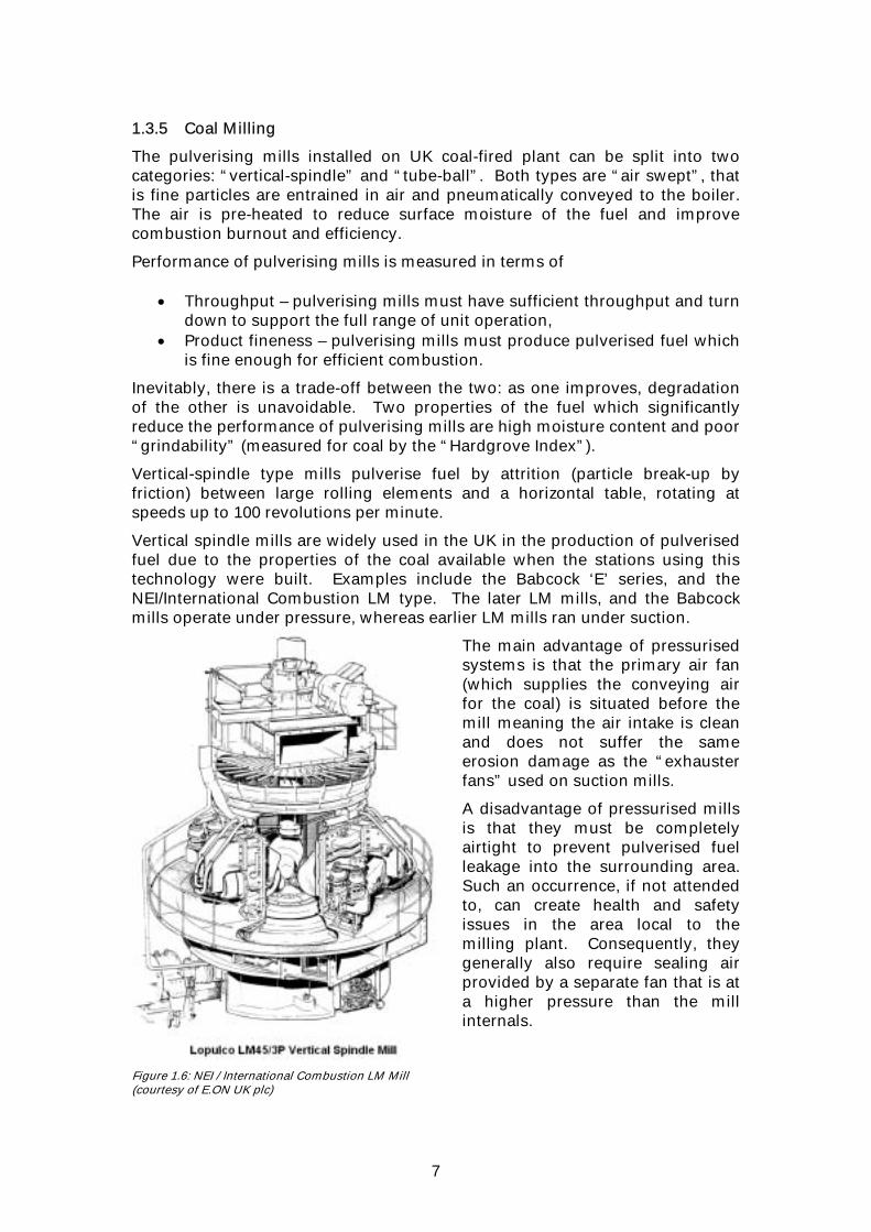
1.3.5 Coal Milling
The pulverising mills installed on UK coal-fired plant can be split into two categories: “vertical-spindle” and “tube-ball”. Both types are “air swept”, that is fine particles are entrained in air and pneumatically conveyed to the boiler. The air is pre-heated to reduce surface moisture of the fuel and improve combustion burnout and efficiency.
Performance of pulverising mills is measured in terms of
• Throughput – pulverising mills must have sufficient throughput and turn down to support the full range of unit operation,
• Product fineness – pulverising mills must produce pulverised fuel which is fine enough for efficient combustion.
Inevitably, there is a trade-off between the two: as one improves, degradation of the other is unavoidable. Two properties of the fuel which significantly reduce the performance of pulverising mills are high moisture content and poor “grindability” (measured for coal by the “Hardgrove Index”).
Vertical-spindle type mills pulverise fuel by attrition (particle break-up by friction) between large rolling elements and a horizontal table, rotating at speeds up to 100 revolutions per minute.
Vertical spindle mills are widely used in the UK in the production of pulverised fuel due to the properties of the coal available when the stations using this technology were built. Examples include the Babcock ‘E’ series, and the NEI/International Combustion LM type. The later LM mills, and the Babcock mills operate under pressure, whereas earlier LM mills ran under suction.
Figure 1.6: NEI / International Combustion LM Mill (courtesy of E.ON UK plc)
The main advantage of pressurised systems is that the primary air fan (which supplies the conveying air for the coal) is situated before the mill meaning the air intake is clean and does not suffer the same erosion damage as the “exhauster fans” used on suction mills.
A disadvantage of pressurised mills is that they must be completely airtight to prevent pulverised fuel leakage into the surrounding area. Such an occurrence, if not attended to, can create health and safety issues in the area local to the milling plant. Consequently, they generally also require sealing air provided by a separate fan that is at a higher pressure than the mill internals.

8
Figure 1.7: – Babcock 10E Mill (courtesy of RWE npower)
Considering, specifically, the 10E mills (Figure 1.7) used at Didcot A, Ratcliffe-on-Soar, Drax and Ferrybridge C Power Stations, raw coal supplied by the feeder enters the mill at the top through a central inlet chute and falls onto the grinding elements. These grinding elements comprise 10 cast steel balls which run between two grooved ‘Elverite’ grinding rings; the lower one rotated by a drive mechanism, but fixed vertically, and the upper one able to move vertically, but fixed to prevent rotation. Primary air is fed to the mill through inlet ducts around the periphery of the lower grooved grinding ring where ground fuel particles are picked up by the primary airstream and carried upwards towards the classifier, where a swirl action is induced and oversized particles are returned to the grinding zone. Rejected material that cannot be pulverised is carried round and discharged into holding boxes, which can be emptied while the mill is in service.
Figure 1.8: Tube Ball Mill (courtesy of RWE npower)
Raw Coal Inlet
Pulverised Fuel Outlet
Primary Air Inlet
Raw Coal Inlet
Pulverised Fuel Outlet
Primary Air Inlet
Primary Air Inlet
Raw Coal Inlet Pulverised Fuel Outlet
Pulverised Coal
Un-ground Coal

9
Tube-ball type mills (Figure 1.8) consist of a rotating horizontal cylinder partially filled with steel balls. Coarse fuel is fed in and pulverised fuel extracted at one end (“single end” type) or both ends (“double-end” type). Particle size reduction is achieved through a combination of impact (larger pieces) and attrition and crushing (finer grinding). As with vertical spindle mills, pulverised fuel from the mill is graded in a device called a “classifier”. Fuel particles above a certain size are separated from the air stream and returned to the mill for further pulverising. The resulting product is blown into the furnace and burnt using standard combustion equipment. 1.3.6 Co-Milling of Biomass
The approach that has currently been adopted to biomass co-firing on most coal-fired power stations in the UK is to pulverise the coal and biomass simultaneously in the existing pulverising mills. This approach has been termed ‘co-milling’, and it allows the simultaneous size reduction and drying of both the biomass and coal, prior to the two fuels being burnt together in the furnace.
Where a co-milling approach is adopted, the biomass and coal may be blended before or after delivery to the power station. The former option is referred to as ‘off-site blending’, and results in a single fuel stream to the power station, which can be handled in a similar way to coal. The latter option is referred to as ‘on-site blending’; where two fuels are delivered to the power station, and require separate reception and handling facilities up until the point where the two fuel streams are blended into one. All stations that are co-milling biomass in the UK are using on-site blending to satisfy Ofgem’s audit requirements. 1.3.7 Direct Injection
“Direct injection” offers an alternative route for supplying co-fired biomass to a coal-fired boiler. This involves the introduction of the biomass to the boiler in a separate stream, through separate burners / injectors. This provides several advantages over co-milling, the most significant being that the biomass does not affect the flow, milling and classification of the coal, and it avoids the unit load limitations that can occur when co-milling with low calorific value coals or biomass. However, this type of installation is much more capital intensive than the limited modifications required for a co-milling approach.
The separate handling of biomass also allows co-firing to be carried out in a plant that has strict limits on volatile content in the coal. Biofuels typically contain around 80% volatile matter (on a “dry ash free” basis), whereas coal-fired plant in the UK are designed to receive coals with dry ash free volatile contents of less than 45% for bituminous coals and 10% for anthracitic coals. This separate handling also has the advantage that problems that would occur when materials with bad milling properties are sent through the mill can be effectively bypassed.
Installations for direct injection schemes have ranged from a simple hopper feeding a pneumatic transport line leading directly into the furnace, to elaborate chipping / grinding plant feeding separate biomass burners with a complete burner control system.

10
1.4 Why Best Practice for Biomass Co-Firing? The Government has set ambitious targets for the country regarding reduction of CO2 emissions. One of the methods to reduce this emission is co-firing of biomass with the considerable amount of coal that is burned by the UK power industry today.
Biomass co-firing provides a relatively low cost means of increasing renewables capacity and an effective way of taking advantage of the high thermal efficiency of large coal fired boilers. It is also recognised within the Government’s Renewables Obligation as an effective means of stimulating the development of a market for biomass fuels and energy crops within the UK.
Many of the utility companies in the UK have developed projects that take advantage of the incentives offered by the Renewables Obligation with regard to biomass utilisation. This experience has raised issues in a number of areas which lead to complications during plant design, construction and commissioning. Consequently, there is a large amount of experience and information regarding combustion and co-combustion of biomass available in the UK, and through the links that have been developed with a range of organisations involved in these activities world-wide.
Through the DTI, the Government is supporting a number of initiatives related to co-firing of biomass at power stations, some examples are summarised below:
• “Biomass Co-Firing at Power Stations”. • “Reducing Slagging and Fouling Constraints on High Level Biomass Co-
Firing”. • “Development of Low-Cost Systems for Co-Utilisation of Biomass in Large
UK Power Plant”.
Although these projects also include elements of dissemination, by themselves they are somewhat fragmented, with overall reporting timescales that are significantly longer than have been achieved with this brochure.
This Best Practice Brochure represents an efficient method of summarising the experiences from all current ongoing biomass co-firing activities in the UK. It is designed to disseminate relevant information between all those involved in biomass co-firing activities, and to speed up the implementation of the most successful methods. It provides details of the solutions that have been adopted to the issues encountered, along with a commentary on those issues that still need to be resolved as further projects are developed and the market drivers change towards the utilisation of energy crop and dedicated biomass combustion plant.

11
2. LEGISLATION All companies have an impact on the environment and as such are morally and legally responsible for managing these effects - and environmental legislation has been developed over the years to ensure that any impact stays within acceptable limits. Environmental legislation tends to be complex and constantly changing. In recent years the volume of legislation concerned with the environment has also increased significantly, and an overview of this legislative framework and its implications for biomass co-firing is provided here.
There are now a number of EU Directives of direct relevance to the power industry. For example, the Integrated Pollution Prevention and Control (IPPC) Directive specifies that Best Available Techniques (BAT) for minimising pollution should be determined for various industry categories, including Large Combustion Plant. The European Pollution Emission Register (EPER), established by a separate decision, under the umbrella of the IPPC Directive, requires Member States to report national emissions of listed pollutants.
In addition to the Renewables Obligation (RO), environmental legislation that has been enacted in the UK which makes specific reference to the use of biomass fuels on power stations includes the Large Combustion Plant Directive (LCPD), the Climate Change Levy (CCL), and the Waste Incineration Directive (WID).
In addition, the alteration of activities in any industry can involve verification of local planning applications to ensure that all permissions are adhered to. Naturally, the same requirements exist for the power industry, and as such the issues that have been raised as a result of co-firing activities are also considered here.
2.1 IPC Authorisations / IPPC Permits The Environmental Protection Act 1990 and the Industrial Pollution Control (Northern Ireland) Order 1997 have created a UK wide pollution control system for industry where any person carrying out a prescribed process must obtain authorisation from the environmental regulator which will contain conditions that they must adhere to.
Throughout the UK, ‘Integrated Pollution Control’ (IPC) is being phased out and replaced by the ‘Pollution Prevention and Control’ (PPC) regime. This implements the EU’s ‘Integrated Pollution Prevention and Control’ (IPPC) Directive within the UK, and builds on many of the same principles as IPC. Under PPC, power stations are classed as ‘Energy Industry Combustion Activities’ and fall within the Part A(1) process category. Permits issued under PPC must be based on the Best Available Techniques (BAT), taking into account the local environmental conditions, geographical location and technical characteristics of the specific installation. The transition to PPC will continue until 2007 and permit applications for large combustion plant should be made between 1 Jan and 31 Mar 2006.
Any person operating an installation or mobile plant after the prescribed date must obtain a permit from the environmental regulator and comply with all the conditions in that permit under the PPC regime.

12
PPC includes new issues not previously covered by IPC such as: • Vibration • Noise • Waste minimisation • Energy efficiency
This new system also requires that an effective management system is in place to ensure that all pollution prevention and control measures are taken. Particular emphasis is placed on the application of Best Available Techniques (BAT) rather than Best Available Techniques Not Entailing Excessive Cost (BATNEEC) to reduce the environmental impact of the process.
Figure 2.1: Cottam Power Station (courtesy of E.ON UK plc)
Before burning biomass material, all combustion plant operating under IPC/IPPC need to apply for approval from the Environment Agency (EA). These applications are made through local EA Area Inspectors, and for the earliest biomass co-firing applications this led to some inconsistency in approach to the approvals given. The EA and the Joint Environmental Programme (JEP) subsequently worked together to produce a protocol for the approval process. This protocol has helped to standardise the approvals for operators and also allowed some streamlining of the process.
The protocol defines the information the EA would require in order to give approval for the burning of any biomass and defines the approach that should be adopted to gathering this information. The first time biomass is burned a trial needs to be carried out, which requires authorisation via a variation application. This is a process that can take several weeks depending on the number of areas that require clarification by the EA inspector. The issuing of a variation by the EA will then authorise trials with a given quantity of biomass fuel up to a specified blend percentage. Once these trials are completed burning has to stop whilst a report considering the Annex A requirements in the protocol is produced (within 28 days) and the report is assessed by the EA. After receipt, the EA have a 28 day period in which to assess this report, although the assessment has often taken longer due to the EA requesting additional information from the operator. Co-firing can only recommence with approval from the EA, which is usually given in the form of a variation to the station’s IPC authorisation, although in some cases it has been provided in a letter without a full variation.
Once the EA has approved the co-firing of biomass, where approval is sought to co-fire additional, similar (in terms of physical and chemical composition) biomass materials, a less extensive evaluation exercise is required. This can be

13
undertaken on the basis of a one week notice period to the EA rather than a full variation application, and continued burning of the new fuel is allowed (unless any negative environmental effects are experienced) whilst the EA is assessing the report of the evaluation exercise. Generally more than one week’s notice has been given to the EA to ensure that the process runs smoothly. Due to the shorter timescales involved, it is likely that approval will be via letter rather than a full variation.
Other biomass materials that are not similar will need to be assessed via the trial process, and evaluation exercises can only be carried out up to the percentages previously trialled unless extrapolation can show that higher percentages will be acceptable.
Whilst the protocol is useful in trying to standardise the process and should be used as a guide for all applications, there are a couple of issues to note:-
- the document only considers biomass materials not currently subject to the requirements of WID, whereas the Renewables Obligation has a wider definition of biomass. As a result, some ROC eligible materials can be delayed and might not be considered in line with the protocol.
- there are no timescales for the EA to assess the trial applications and in some cases the delays associated with these assessments have been relatively long.
2.2 Large Combustion Plant Directive (LCPD) and Pollution Control
The revised Large Combustion Plant Directive (LCPD) is particularly important since this establishes emission limits values (ELVs) for new and existing plant, in addition to making further provision for pollution inventory reporting in support of the European Pollution Emission Register (EPER) requirements. However, it should be noted that it is necessary to satisfy the requirements of both the LCPD and the IPPC Directive.
Existing combustion plant (approved before 1st July 1987) must either observe lower emission limits, or achieve equivalent emission reductions via a national emissions reduction plan, by 2008, unless it is intended to close the plant after a further 20,000 operating hours between 2008 and the end of 2015. Plant that is upgraded to meet the Part A Emission Limit Values, defined in the Annexes of the Directive, is ‘opted in’. Plant that is designated for eventual closure is ‘opted out’.
The LCPD limit values for existing and new plant larger than 300 MWth are given in Table 2.1. There are specific requirements for both monthly averages and 48 hour averages, and numerous caveats within the text of the Directive. Continuous emissions monitoring is required for all plant greater than 100 MWth and the LCPD also requires compliance with CEN standards relating to the quality assurance of these monitoring systems.

14
Table 2.1: Nominal LCPD Emission Limit Values for Large Plant (>300 MWth)
Existing (Part A)* New (Part B)
Fuel Type: Solid Liquid Gas Solid Liquid Gas
SO2 400 400 35 200 200 35
NOx 500 400 200 200 200 100
Dust 50 50 5 30 30 5
Ref. O2 dry 6% 3% 3% 6% 3% 3%
* Valid until 31 December 2015
Since 2004, each large combustion plant must also report an inventory of total annual SO2, NOx and dust emissions and the total annual energy input and net calorific value by fuel type. Biomass is identified as a separate fuel category, in common with the provisions of the EU Guidelines for the Monitoring and Reporting of Greenhouse Gas Emissions.
The LCPD defines biomass as any product consisting of vegetable matter from agriculture or forestry which can be used as a fuel for the purpose of recovering its energy content. The LCPD also includes a list of biomass wastes that are exempt from the provisions of the Waste Incineration Directive (see Table 2.2). Table 2.2: Biomass Wastes that are Exempt from the Provisions of the
Waste Incineration Directive
• vegetable waste from agriculture and forestry
• vegetable waste from the food processing industry (with heat recovery)
• fibrous vegetable waste from virgin pulp and paper production from pulp, if it is co-incinerated at the place of production and the heat generated is recovered
• cork waste
• wood waste with the exception of wood waste which may contain halogenated organic compounds or heavy metals as a result of treatment with wood preservatives or coating, and which includes, in particular, such wood waste originating from construction and demolition
N.B. List limited to Renewables Obligation biomass likely to be co-fired in fossil fuel fired plant. See the Waste Incineration Directive (Article 2, Paragraph 2) for complete list.
2.3 Levy Exemption Certificates As part of a range of measures to help the UK meet its commitment to reduce greenhouse gas emissions and create a low carbon economy, the UK Government introduced the Climate Change Levy (CCL) on industrial and commercial (I&C) users in April 2001.
Under this scheme, industrial and commercial (I&C) users of electricity must pay an additional £4.30/MWh for their electricity. Payments are made to the HM Customs & Excise (HMC&E) and partly administered by Ofgem. These payments can be avoided by either investing in energy efficient machinery

15
(80% rebate), or purchasing a Levy Exempt Certificate (LEC) as evidence of having consumed a unit of electricity (1 MWh) generated using renewables (100% rebate). It is generally thought that the I&C user is prepared to pay up to £4.00/MWh to the electricity supplier for a LEC which enables them to avoid paying £4.30/MWh to HMC&E and that the electricity supplier in turn would pay up to £3.40/MWh for a renewable LEC to the generator, meaning that the electricity supplier is the essential link. The final value that the generator receives for renewable LECs is subject to negotiation and market-based, and therefore unstable until contract completion.
In addition, the EU Emission Trading Scheme (ETS) was launched on 1st January 2005. Both of these measures may award value to renewable generators, because renewable generation is exempt from the CCL and from the EU ETS. The CCL exemption can be traded through LECs, whereas carbon values from the ETS are likely to be passed on through higher wholesale electricity prices.
2.4 Renewables Obligation The Renewables Obligation was introduced on 1st April 2002, and extended to Northern Ireland in 2005. It is effective until 31st March 2027 and has the following goals:
• Increasing the amount of electricity generated from renewable energy sources to 15.4 percent of total supply by 2015.
• Reducing carbon dioxide emissions. • Maintaining investor confidence in the development of renewable
energy sources. • Development of an integrated UK biomass production and utilisation
industry.
It requires all licensed electricity suppliers in the UK to supply a specified proportion of their electricity sales from a choice of eligible renewable sources, and provides a number of paths to compliance. This is the key instrument the Government is using to influence the growth necessary to reach the UK’s renewable energy targets in the power sector.
Eligible renewable energy sources include:
• Landfill Gas • Sewage Gas • Hydro (20 MW or less, and larger stations commissioned after 1 April 2002) • Onshore and Offshore wind • Geothermal power • Tidal & Tidal Stream power • Wave power • Photovoltaics

16
• Biomass: - Combustion in dedicated plant. - Co-firing biomass and energy crops (subject to restrictions detailed in
Table 2.3). - Pyrolysis, gasification & anaerobic digestion of biomass and
biomass/waste blends (such plant can only claim ROCs for the biomass component of mixed waste).
For the purposes of the Renewables Obligation, biomass is defined as a “fuel from which at least 98% of the energy content is derived from plant or animal matter”.
‘Renewable Obligation Certificates’ (ROCs) are awarded for eligible renewable generation from the above technologies. One ROC is issued to a generator for each MWh of qualifying electricity produced, and generators then sell their ROCs to electricity suppliers. ROCs are worthless if they are kept by the renewable generator and not sold to a supplier for redemption. A combination of ROCs and buy-out payments (valued at £32.05 per MW/h in 2005/06, with subsequent values increasing in line with the retail price index) are collected from electricity suppliers, to a value sufficient to achieve the target for the year (the ROCs are redeemed by October 1st every year). Buy-out payments are recycled to those suppliers that redeem ROCs (often referred to as the ”green smear”).
The Renewables Obligation will remain in place until 2027 in order to try to provide for stable and long-term production of electricity from renewable energy sources. Yearly targets have been set up until the 2015/16 period.
In order to limit the impact of large scale co-firing on the ROC market, restrictions have been placed both on the fuels used at co-fired stations and an electricity suppliers ability to demonstrate compliance with the Renewables Obligation using co-fired ROCs.
Biomass co-firing will only be eligible for ROCs until 2016, and the proportion of co-fired ROCs that can be redeemed by any particular supplier is capped. In 2006 this cap reduces from the current level of 25% of a suppliers obligation to 10%, halving the predicted maximum number of co-fired ROCs that could be claimed, with a further reduction to 5% in 2011. Although this legislation is not currently limiting renewable generation output from co-fired plant, this tightening of the co-firing cap is expected to impact upon the amount of renewable generation derived from biomass co-firing.
The introduction of an additional requirement to obtain biomass from energy crop sources is likely to create a further impact. From 2009 onwards an increasing proportion of the fuel used for co-firing will have to be sourced in this way. Energy crops are defined as crops planted after 31 December 1989, and grown primarily for the purpose of being used for fuel.
Details of the targets and restrictions on co-firing, as they are currently defined, are set out in Table 2.3.

17
Table 2.3: Targets and Restrictions on Co-Fired Renewable Generation
Year
Estimated UK Sales by
Licensed Suppliers
(TWh)
Suppliers Obligation
(% Renewables)
Total Obligation
(TWh)
Co-Firing Cap (%)
Predicted Maximum Co-Fired ROCs (TWh)
Proportion of Co-Firing to be Energy
Crop (%)
2001/2002 310.9 * 25 - 2002/2003 313.9 * 3.0 9.4 25 2.4 - 2003/2004 316.2 * 4.3 13.5 25 3.4 - 2004/2005 318.7 * 4.9 15.6 25 3.9 - 2005/2006 320.6 * 5.5 17.7 25 4.4 - 2006/2007 321.4 * 6.7 21.5 10 2.2 - 2007/2008 322.2 * 7.9 25.4 10 2.5 - 2008/2009 323.0 * 9.1 29.4 10 2.9 - 2009/2010 323.8 * 9.7 31.5 10 3.2 25 2010/2011 324.3 † 10.4 33.6 10 3.4 50 2011/2012 325.2 † 11.4 37.1 5 1.9 75 2012/2013 326.0 † 12.4 40.4 5 2.0 75 2013/2014 326.7 † 13.4 43.8 5 2.2 75 2014/2015 327.5 † 14.4 47.2 5 2.4 75 2015/2016 328.2 † 15.4 50.5 5 2.5 75
* Source = DTI † = extrapolated data
The Government is currently reviewing the legislative framework that should be put in place beyond 2015. They have said that no major changes that will create uncertainty for project developers will be undertaken.
2.5 Renewables Obligation Certificate Qualification Ofgem have been appointed by the Government to manage the application of the Renewables Obligation Order in England, Wales, Scotland and Northern Ireland. The full procedure for generators in these geographical areas can be found on their website.
Ofgem has to accredit the power plant, any fuel used, and the process in order to issue ROCs. 2.5.1 Accreditation In order for ROCs to be issued, the generating station must have applied to Ofgem for accreditation prior to the generation of eligible electricity. The accreditation application form also covers eligibility for the Climate Change Levy (CCL) and Renewable Energy Guarantees of Origin (REGOs). [REGOs certify the eligibility of generated power under the EU Renewables Directive, through a system that is mutually recognised between EU Member States. They enable trade in renewable energy across national boundaries.]
18
Accredited stations are categorised under the Renewables Obligation based upon the fuel used to generate electricity at the station as a whole, rather than individual generating sets.
A co-fired biomass fired plant may use a waste, such as reclaimed fuel oil (RFO), for specified purposes without changing its Renewables Obligation eligibility, providing the energy content of this fuel does not exceed 10% of the total used for generation. The specified purposes are the ignition of gases; heating of the combustion system and maintenance of that temperature; emissions control; and standby generation. 2.5.2 Eligible Output ROCs are issued based upon eligible electricity generated in each calendar month. Eligible power must be both generated in the UK from eligible renewable sources and supplied by a licensed supplier to consumers in the UK. Where the electricity is consumed on site for purposes other than generation, a sale and buyback contract can be arranged with a licensed supplier to ensure eligibility.
Generators are required to submit monthly ROC claims within two months of the end of the month of generation, and Ofgem provide a standard template for these. Late submissions are rejected.
The following data is obligatory for biomass co-fired stations:
• Gross Output – the total electricity generated in the month.
• Input electricity – electricity used for purposes relating to the operation of the generating station, whether generated by that station, produced by standby generators or imported.
• Measurement of all fuels used for generation - quantities, gross CV and evidence that the biomass meets the 98% pure requirements. All measurements must be taken at the generating station, within the month that the fuel is burnt. Any residual fuel left at the end of the month must be re-sampled for use in the next month.
Ofgem may request any additional data they see fit to verify the reliability and accuracy of the claim. They also reserve the right to audit any generating station claiming ROCs. Ofgem have the right to refuse to issue ROCs if they are not satisfied with any aspect of the information provided.
In order to reduce the risk of a claim being rejected due to inadequate or inappropriate supporting evidence, it is recommended that generators submit their proposed fuel handling and measurement procedures to Ofgem for approval before generation commences. 2.5.3 ROC Issue & Revocation
The ROCs in respect of successful claims are issued to the generators account on the ROC register, normally one month after the deadline for claims.
Ofgem retain the powers to revoke a ROC, once issued, if they have reason to doubt the accuracy or reliability of the information considered in issuing the ROC. Revoked ROCs will be deleted from the current holders account on the ROC register. Any replacement ROCs will be issued into the relevant generators account. Most ROC purchasing contracts reflect this revocation risk.

19
2.6 Renewables Obligation Auditing
Under the Renewables Obligation Order, Ofgem is only authorised to issue ROCs once it is satisfied that a number of relevant criteria have been met, including:
• That the Authority has been provided with all the information that it reasonably requires in order to assess whether ROCs should be issued.
• That the Authority is satisfied that such information is accurate and reliable.
Consequently, as well as operating routine checks and controls, Ofgem carries out audits each year on a sample of generating stations. The sample is chosen partly at random but also taking account of particular factors, which could include those generating stations with the most complexity or which attract the most ROCs. Ofgem normally authorises independent consultants to carry out these audits on its behalf but may request any station to provide access to Ofgem’s staff. The auditor is required to audit a sample of stations to check whether:
• Information that has been provided for accreditation is correct and the station has been properly accredited.
• Metering arrangements and meter readings/output volumes notified to Ofgem are such that the correct number of ROCs are being issued each month.
Ofgem carried out 20 audits of accredited generating stations during the first obligation period. The sample size has been increased in subsequent years and will be maintained at a level deemed necessary to ensure the integrity of the scheme. Whilst most of the outcomes were satisfactory, some recurring issues did arise, these being:
• Definition of a ‘Generating Station’ • Definition of ‘Input Electricity’ • Definition of ‘Eligible Own Use’ • Definition of ‘Minimal Fossil Use’ • Classification of Generating Stations and calculations for ROCs
The requirements to be met to claim for co-fired ROCs are contained in the Renewables Obligation Order 2005 (which replaced the Renewables Obligation Order 2002 and the Renewables Obligation (Amendment) Order 2004).
Generators are advised to read these documents with care. To avoid misinterpretation, Ofgem encourage the submission of a proposed ROC claims procedure prior to commencing co-firing, and are willing to meet with generators to discuss how the biomass measurement requirements can be fulfilled at each station. Whilst the fundamental principles established within the legislation are clear, the implications of the detailed requirements for biomass sites are not immediately apparent. Additional guidance on Ofgem’s interpretation of these requirements is however available on their website.
Given the complexities of the Orders, it might be expected that biomass generators would experience some difficulties at the start of the scheme and the audit findings to date seem to bear this out. Where misunderstandings and disputes have arisen, the absence of an appeals mechanism under the Renewables Obligation and the lack of transparency has in many cases compounded issues experienced by generators.

20
The most significant issue that has affected a large number of generators has been Ofgem’s interpretation of ‘fuel used at a generating station’ and its decision that the pre-blending of biomass with coal at a remote location did not satisfy its requirements for accuracy and reliability unless the component fuels could be measured on site. One consequence of this has been that the risk of generation subsequently proving to be ineligible for ROCs now features strongly in the generators’ renewables (particularly biomass) investment decisions.
As a result of the audits, Ofgem issued further clarification to generators and entered into detailed correspondence with many generators to ensure that electricity is being measured correctly as either ‘input electricity’ or ‘eligible own use’. The clarification tends to deal in principles and where there is uncertainty generators would be advised to seek early guidance from Ofgem on the technical methods proposed for compliance. It is noted that due to concerns regarding commercial confidentiality RO procedures operating at existing biomass sites are not transparent.
The audits highlighted that generators were not always completing application forms correctly, and Ofgem has revised the form and the accompanying guidance note with the aim of reducing the occurrence of common mistakes.
Some generating stations audited had not been advising Ofgem of certain information of relevance to the issue of ROCs. Of these omissions, the most significant were identification of where metering data had been estimated, information with respect to the use of diesel standby generators, and failure to sample biomass supplies in the particular month for which ROCs were to be claimed. Ofgem will accept estimated output data in certain cases but only where it is notified and agreed in advance. However, the sampling and measurement of biomass and other fuels must always be carried out in respect of the fuel burned in the month in question. Ofgem’s procedures on the Renewables Obligation and its guidance on fuel sampling and measurement are both available on Ofgem’s website.
Ofgem requires generators to provide accurate and complete information and to notify them of any changes to the information originally provided. This is so Ofgem can properly assess the accreditation and issue the correct number of ROCs each month. While the majority of generators have complied with this requirement, there have been cases where certain information has only come to light through the audits with Ofgem refusing to issue the ROCs until it is satisfied with the accuracy and reliability of the information provided.
Where a claim satisfies Ofgem’s requirements for accuracy and reliability, ROCs will be issued approximately one month after the deadline for submission (3 months after the month of burn). However:
• The administrative requirements of the Renewables Obligation for biomass utilisation and the complexity of the processes involved should not be underestimated.
• Pre-existing heat accountancy and analysis procedures are unlikely to be sufficient to meet audit requirements.

21
• All metering, sampling and analysis for claim submissions should be undertaken in the month to which the claim applies.
• Extensive details are generally required in areas such as: - Monthly sampling methodologies - Analysis techniques, contamination etc
- Use of oils - “Standby generators” - Fuel contracts
• Requirements may change with time - the onus is on the generator to monitor for these changes and respond accordingly.
Where there are problems with a ROC claim procedure this may not come to light until after the ROC claim is processed (up to 3 months after generation) and it may be some considerable time before the issue can be resolved to Ofgem’s satisfaction. Consequently, in a number of cases, generators have built up large financial liabilities with respect to their ROCs claims.
2.7 Waste Incineration Directive The Waste Incineration Directive (WID) (OJ L 332/91, 28 Dec 2000) was to be transposed into each Member State’s national legislation by 28 December 2002. In the U.K., this is embodied in The Waste Incineration (England and Wales) Regulations 2002. The WID has applied to all new waste incineration installations since 28th December 2002 and applies to all existing installations co-firing certain wastes from 28 December 2005.
The purpose of the directive is to limit or prevent, as far as practicable, negative effects on the environment, in particular pollution by emissions into the air, soil, surface and groundwater, and minimise the resulting risks to human health from the incineration and co-incineration of waste. The Directive will require the setting and upholding of stringent operational conditions, technical requirements and emission limit values for plants incinerating and co-incinerating waste throughout the European Community to achieve a high level of environmental and health protection.
Given the broad European definition of a waste as “any substance …… which the holder discards or intends or is required to discard”, there is a concern that certain biomass types that may not be traditionally viewed as such, could be classified as wastes, requiring compliance with the Waste Management Regulations. This could, therefore, apply to some materials that are exempt from the provisions of the WID (see Table 2.2 for a list of specific biomass wastes that are WID exempt). 2.7.1 Waste, the Renewables Obligation and the Waste Incineration
Regulations Under the Renewables Obligation Order 2002 (RO), “Biomass” is defined as a material in which at least 98% of its energy content is derived from plant or animal matter when it is used as a fuel. This may include the co-firing of waste (e.g. municipal solid waste fractions) to produce ROCs – as long as the waste materials meet this definition.

22
Generating stations may fire unadulterated, plant derived, biomass products and by-products without reference to the WID. They may also fire plant derived biomass waste that is WID exempt (see Table 2.2). Both are eligible for ROCs. However, if a biomass waste is not WID exempt the station would be subject to some of the additional requirements specified by the WID, e.g., much more stringent air emission limit values, reduced flexibility with regard to operating conditions additional measures relating to water discharges from exhaust gas cleaning, ash recycling, plant control and monitoring, and public access to information. The Directive requires all incinerators and co-incinerators to have continuous monitors for a wide range of pollutants. It should be noted that the emission limits set by WID are much more severe than those in the LCPD. For example, NOX is limited to 200 mg/Nm3 by the WID, whereas the LCPD would only require compliance with these limits after 2016, imposing a limit of 500 mg/Nm3 between 2008 and 2016. It is, therefore, generally uneconomic for an existing generating station to burn biomass that is not WID exempt. 2.7.2 Implications of the WID after December 28th 2005 Existing fossil-fuelled stations which are co-firing biomass to generate renewable electricity will be unable to meet the requirements of WID without significant investment. This means that co-firing of any biomass which is classified as a waste but not exempt from the WID will have to stop after 28 December 2005, reducing the potential contribution of co-firing to renewable energy targets. If a decision is made to upgrade the plant to meet WID standards and co-fire non-excluded waste, a WID permit application (or early IPPC application) had to be submitted to the Environment Agency by 31 March 2005. 2.7.3 Implications of the WID prior to December 28th 2005 Prior to 28 December 2005, an “existing co-incineration plant” can continue to co-fire any biomass waste without having to meet the WID requirements. To qualify as an existing co-incineration plant, the fossil-fuelled station must have co-fired a waste, with the appropriate permit/authorisation, prior to 28 December 2004.
Where stations are already co-firing a waste which is not WID exempt, a WID application had to be submitted by 31/03/05, including a BAT statement for co-firing the biomass, to permit confirmed co-firing to 28th December 2005. 2.7.4 Impact of WID and Waste Classification on Biomass Co-Firing Since most of the ROC-eligible biomass materials likely to be co-fired are exempt from the WID (see Article 2 Paragraph 2 of the Directive, and Figure 2.7 below), the impact on renewable generation from co-firing may be small. However, it should be noted that any animal derived waste biomass will not be WID exempt and co-firing of these materials will have to stop from 28 December 2005. Where biomass of animal origin is not deemed to be waste, such products will automatically be excluded from the WID, allowing their use in co-firing beyond this date.

23
However, classification of biomass as a waste, even when WID exempt, may result in substantially increased costs arising from compliance with Waste Management Regulations, and individual organisations will have to verify their Duty of Care Requirements for the transportation of such biomass fuels.
This may have a significant negative impact on the supply of biomass as a renewable energy source. The waste classification of a material should not be dependent on its end use. Where there is an existing market for a biomass, i.e. it is not discarded, a new market for the biomass in renewable generation should not be viewed as a disposal route and should be treated in the same way as existing applications. Figure 2.7: WID Exemption for ROC’able Biomass Wastes
There is a concern that local Inspectors may incorrectly apply guidance from other industry sectors to the energy sector. For example, the guidance for the food and drink sector states that materials resulting from the manufacture of food or drink that are destined for human or animal consumption are not waste. However, these same residues are regarded as waste if they are used as a fuel. This guidance may be relevant to small food and drink manufacturers in possession of a surplus that they would otherwise intend to discard. However, this is not relevant to material that is, for example, traded in large volumes as a high value commodity on the animal feed market.
A material is either a waste (the intention is to discard) or a product. Otherwise, there is the prospect of imported material requiring waste transfer notes when used by a power station but not requiring these notes when used by the food and drink industry.
However, it should be noted that the Environment Agency has confirmed that all of the plant derived biomass materials co-fired in the UK to date are exempt from the WID even if these could be classified as waste under some circumstances.
2.8 Local Authority (Planning Consents) 2.8.1 Interaction with Section 36 Consent Development consent for new electricity generating stations over 50 MWe is required under Section 36 of the Electricity Act 1989. It is a comprehensive
1. Dependant on meeting RO requirements for energy crops 2. List limited to RO biomass likely to be co-fired in fossil fuelled plant. See the WID for complete list.
NO
Is the biomass awaste?
YES
Can co-fire to31/03/20161
Is it: 2
•Vegetable waste from agriculture andforestry?
•Vegetable waste from food processing?
•Wood waste free from coatings and preservatives?
YES
NO
It is WID EXEMPT and can be co-fired to 31/03/20161
It is NOT WID EXEMPT and can only be co-fired to 28/12/2005

24
procedure in which the views of the local planning authority, local people, statutory bodies such as the Environment Agency, Countryside Agency and English Nature/Countryside Council for Wales, and other interested parties can be brought into the decision making process. All applications are routed to the local planning authority and will, therefore, appear on the local planning register, and in certain circumstances a public inquiry may be called before a final decision is made by the Secretary of State.
Figure 2.2: Kingsnorth Power Station
All biomass co-firing schemes involve some extension of power station facilities and some change in operation. To date, experience of such schemes in the UK suggests that the Department of Trade and Industry does not consider these changes sufficient to require Section 36 consent under the Electricity Act 1989. However, operators should satisfy themselves that Section 36 Consent exists or is not required, for their schemes.
2.8.2 Use of Permitted Development Rights Part 17 Class G of Schedule 2 to the Town and Country Planning (General Permitted Development) Order 1995 (SI 1995 No. 418) (as amended) (“the GPDO”) permits certain developments for electricity generating purposes by generation licence holders including:
• The extension or alteration of buildings on operational land;
• The erection on operational land of the undertaking of a building solely for the protection of plant and machinery;
• Any other development carried out in, on, over or under the operational land of the undertaking.
A biomass co-firing scheme can often be installed under these permitted development rights without specific planning permission, saving time and cost. If these rights are used, the height of any new building or structure must not exceed 15 metres above ground level or the height of any structure replaced. The approval of the local planning authority is still required for the external design and appearance of any new building (but not for other works) before works are begun.
These permitted development rights only apply on “operational land”. Although the legal definition of such land is complex, land which is within both the original consented area of the power station and the station security fence will normally be operational land.
Although, in general, biomass scheme buildings have been accepted as permitted development, a local authority may consider that such buildings are not “solely for the protection of plant and machinery” (being partly for the reception and storage of the biomass) and require the operator to apply for planning permission for them. It should always be checked that the local authority agrees that such buildings are permitted development.

25
2.8.3 Permitted Development Rights and Environmental Impact Assessment
Permitted development rights do not apply if a project needs environmental impact assessment (EIA). If the total area of a biomass facility (including construction area) does not exceed 0.5 ha EIA is not normally required and permitted development rights may be used, unless the power station is in a “sensitive area” as defined in Regulation 2 of the Town and Country Planning (Environmental Impact Assessment) (England and Wales) Regulations 1999 (SI 1999 No. 293) (as amended) (“the Planning EIA Regulations”). “Sensitive areas” include National Parks, Areas of Outstanding Natural Beauty, Sites of Scientific Interest and European Sites to which the Conservation (Natural Habitats &c) Regulations 1994 (SI 1994 No.2716) (as amended) apply, among others.
If the area involved is over 0.5 ha or the site is in a “sensitive area” then the biomass scheme will be “Schedule 2 development” under the Planning EIA Regulations, for which EIA may be required at the discretion of the local planning authority. In such cases a “screening opinion” as to whether EIA is required should be sought from the local planning authority under regulation 5 of the Planning EIA Regulations. These regulations require a response to be issued within three weeks. The opinion will be based on the authority’s view of whether the scheme is likely to have significant impacts and the authority may well determine that EIA is not required in which case permitted development rights can still be used. Where an EIA is required, the developer can apply for a ‘scoping opinion’ regarding the site specific aspects that should be addressed in the assessment, in addition to the general guidance on the content of the EIA, which is available within the regulations. The application for a ‘scoping opinion’ should contain as much information as possible and can take the form of a ‘scoping report’ and attempt to ‘scope out’ issues which are known not to be significant. The local authority will consult both its internal consultees (such as the environmental health officer) and external consultees (such as the Environment Agency, English Nature and English Heritage). A scoping opinion should be delivered within 5 weeks of an application. However, this is only an ‘opinion’ and unless items have been specifically ‘scoped out’ the developer is responsible for providing all the information required by the local authority and statutory consultees in order to allow them to determine the application.
The developer is then required to undertake an EIA, and produce an Environmental Statement (ES) to accompany the planning application. The period for determination of the planning application is extended from 8 to 16 weeks for an EIA application. 2.8.4 The Aberthaw Experience
The original proposal for co-firing biomass at Aberthaw included a wood yard, buildings to house wood processing equipment, a processed wood storage facility and associated conveyors. Permitted development rights could not be used because the conveyor height exceeded 15m and if the scheme required EIA this would also negate the PD rights.
An application for a screening opinion was made in August 2003 and the local authority advised that (in their opinion) the development required EIA because it had the potential for significant impacts. The particular concerns that were stated were – the transportation of wood to the site, the sources of wood and

26
the sustainability of the scheme, the potential for impacts on nearby SSSIs, noise, air pollution, effects on the aquatic environment and visual impacts. The scoping opinion that followed did not add anything to this and so a draft scope for an EIA was produced as a consultation document and meetings were convened with the local authorities and statutory consultees.
This consultation process established that the local authority’s main concerns related to impacts on the local community, in the form of road traffic, dust, noise and visual impacts. The local authority also raised the following unexpected concerns:
• Sustainability – the planning authority wished to establish that the scheme was sustainable and required details of proposed sources of fuel supplies.
• Biomass Supply Chain Impacts – the planning authority required details of what impacts could be expected if agricultural land was used for biomass production. Estimates were required of the area of land that would be utilised, where this land might be, and what the landscape and transport impacts would be.
Having established the scope of the EIA, consultants were appointed to assess Ecology, Landscape & Visual, Noise and Traffic impacts, whilst other aspects were addressed in-house. During the studies, discussions were held with the local authority and the findings fed back into the design of the project. This led to changes to the specification of the plant to comply with the local authority’s noise requirements, the incorporation of a landscaping bund and the agreement of a set highway route for all traffic.
The studies were completed early in 2004 and the planning application and environmental statement submitted at the end of March. The application went before a planning committee in July with a planning officer’s recommendation for approval; however the committee deferred the decision because some of the council’s own internal consultees had not returned their comments. The application was approved at the next meeting in September and the process from screening application to consent had taken approximately 13 months.
Figure 2.3: Aberthaw Power Station (courtesy of RWE npower)

27
2.9 Legislative Changes The Renewables Obligation mechanism relies on investor confidence. Significant changes resulting in increased numbers of ROCs becoming available from additional sources that have not previously been eligible are likely to reduce re-cycle values and increase uncertainty in the market.
The Renewables Obligation Order is in place until April 2027. However, the Government has already made several amendments to the legislation to address unforeseen operational difficulties and to ensure it delivers its renewable targets. They are currently undertaking a further review of the legislation.
The amendments introduced in April 2004 extended the opportunities for co-firing, in order to allow time for the development of a biomass supply chain and to increase the uptake of indigenous energy crop resources. As a result, the Government has announced that it does not intend to consider changes to the regulations governing co-firing as part of the current review.
One of the most significant areas of debate is, however, a proposal to allow renewable-qualifying power generation from the biomass fraction of mixed wastes without requiring application of advanced technologies.
The current review is also expected to include consideration of the administration of the Obligation. The experience of those plant currently involved in utilising biomass as a renewable energy resource would suggest that there is significant scope for such a review to improve the processes that are currently in operation. Specific outcomes are expected to include streamlining of ROC claim procedures and relaxation of the stringent rules governing the measurement of fuels.
Another area addressed via amendment to the Renewables Obligation has been the loss of ROC value due to supplier default. The administration of TXU highlighted the risk of a supplier failing to fulfil its Renewables Obligation liabilities, thereby reducing the value of the buyout fund recycle. The Renewables Obligation Order 2005 places a liability on the remaining suppliers to make additional mutualisation payments to address all but a minimal shortfall, up to a cap of £200 million. The mutualisation payments are to be made approximately a year after the initial default, so there is still some cost associated with supplier default which will be factored into ROC prices, however, these should minimised.
The European Commission is reviewing the renewable subsidy mechanisms operated by Member States. In advance of its report it has already confirmed that there are no plans to interfere with the operation of the Renewables Obligation.

28
3. COMMERCIAL
3.1 Fuel Compatibility The economic benefits of biomass co-firing can easily be outweighed by the commercial implications of any adverse impacts on load capability, particularly where there is a need to achieve flexibility with respect to overall plant operation. This makes assessing the compatibility of any particular biomass fuel an extremely important aspect of the fuel procurement process.
The impact that a biomass fuel has on plant operation will be dependent on the type of plant involved, especially the configuration of the milling plant if the biomass is to be co-milled, and the range of coals with which the biomass is to be co-fired.
Figure 3.1: Biomass Fuels (courtesy of E.ON UK plc)
Basic assessment of any new biomass material proposed for a particular plant is typically carried out through a combination of standard fuel analysis techniques, single mill testing and full unit trials. In this way, the following aspects of each fuel are assessed with respect to the co-firing approach to be utilised for commercial biomass co-firing operations:
• fuel analysis, particularly the calorific value of the fuel, its moisture content, its volatile matter content (used to provide a measure of the reactivity of the fuel and the level of risk associated with blending it with higher volatility coals), and its trace element content (which must lie within limiting levels agreed with the EA).
• bulk handling characteristics in terms of dust generation, mechanical stability and odour.

29
• compatibility with existing plant, particularly the bunkers, feeders and milling plant (where the biomass is to be co-milled), taking into account the impact that each biomass fuel has had on mill throughput, and how this varied with the proportion of biomass blended with the coal.
• combustion characteristics, particularly fuel burn-out, due to the adverse impact poor burn-out has on electrostatic precipitator performance, fly-ash sales, and overall plant efficiency.
With increasing operational experience, a database of these fuel properties can be developed. This can then be used when undertaking initial evaluations of the applicability of new fuels for a particular application. This will form part of the value assessment process, which includes consideration of the relative price of a fuel, its availability, and its calorific value or heat content.
However, following this initial evaluation and in lieu of any additional experience or evaluative tools, there is still a need to undertake full scale plant trials on any biomass fuels that are considered worthy of further consideration for longer term commercial co-firing. These tests are required to fully assess the fuel’s compatibility for a particular application and determine the maximum blend ratio that can be utilised for longer term commercial operation. Experience has shown that it is only during larger scale trials that any issues with material handleability will become fully apparent.
It has been found to be important to complete this process for each new biomass fuel considered, and in some cases even for apparently minor changes to fuel specifications. In a number of cases the performance of the fuel handling and milling systems have been found to be particularly sensitive to changes in the physical properties of the biomass fuels. As these sensitivities can reduce the proportion of biomass that can be co-fired, or even require tighter specification of the feedstock, it is important that they are assessed either as part of the full unit plant trials or during the early stages of commercial operation on any particular fuel.
Completion of this evaluation process will often result in a very limited range of fuels being considered suitable for any particular biomass co-firing application. Experience has, however, shown that the range of fuels selected will be plant specific and dependent on a number of factors including the required co-firing levels, the operating regime on the plant, the design and general condition of the fuel handling and milling systems, and the range of coals with which the biomass is to be co-fired.
Clearly, such limitations can restrict the flexibility of biomass co-firing operations. Where this is seen as a limiting factor in the potential commercial success of co-firing, there are a number of improvements which can be made to increase the co-firing capability and widen the range of biomass fuels that can be successfully co-fired on a commercial basis. Many of these improvements will be discussed in later sections of this document, and include those designed to increase biomass throughput, improve blend control, reduce dust levels and mould growth, and avoid spillages of biomass materials. In many cases they result in higher capital and revenue costs, particularly where there is HSE involvement in the resolution of occupational health and safety issues associated with the operations.
A specific example of where such improvements have been made, is in the efforts undertaken to improve mill availability and reliability when co-milling

30
biomass fuels. At one location, during early commercial biomass co-firing operations, considerable problems were encountered with bunker hang-ups and associated mill availability issues. The plant was a 500 MW T-fired unit with vertical spindle mills, and consequently the mill reliability issues led to increased secondary fuel (oil) usage, primarily for ensuring continued combustion stability in the event of losing fuel supply from a particular mill group. This was particularly the case when the unit was being operated at lower load conditions. Consequently, the biomass blend proportion was decreased to a level which ensured these problems were avoided, but resulting in a much reduced biomass firing capacity which had a significant impact on the commercial viability of the project.
In response to this and other issues, capital investment was made to develop bespoke blending plant. The improvements in blend quality achieved following the commissioning of this plant, along with the re-lining of some bunkers led to notable improvements in bunker flow characteristics and reduced incidence of bunker hang ups when co-milling biomass. Consequently, it has been possible to increase the quantities of biomass fired, and the requirement for oil firing for combustion support has been reduced.
3.2 Ash Quality / Utilisation Despite the large differences between the constituents of raw biomass and coal ash, the composition of the co-fired ash is generally dominated by the silica and alumina compounds associated with coal ash. This is due to a combination of the low ash content of typical biomass fuels and the relatively low co-firing rates that are used.
For some biomass fuels, increases in the quantity of alkali metals present within co-fired ashes will be expected, and this raises some concerns with respect to the longer-term corrosion implications of co-firing biomass fuels. Prior to trials being undertaken on the fuels, specific concerns were also expressed over the high phosphorous content of some fuels and the risk this might present to plant staff involved in ash bulk handling operations. However, trial results indicated that the impact of co-firing on the phosphate content of the ash was minimal and within the range encountered with the world traded coals utilised on UK plant. Also, because of the combustion processes involved, any compounds of this type in the ash will generally be apparent in vitrified forms.
The specifications against which biomass fuels are purchased, generally include requirements intended, in part, to minimise any adverse consequences of co-firing on the quality and trace element content of the fly ash. These include the requirement that all biomass feedstocks shall be clean and free from preservatives, additives or other contaminants, requirements which are also designed to ensure compliance with the purity limits defined by Ofgem for the fuels to be ROC eligible. As a consequence, the overall impact of co-firing biomass with coal has generally been to slightly reduce the quantities of most trace elements apparent in the ash.
By far the greatest concern when considering the impact of biomass co-firing on ash quality has, however, been the impact it might have on ash sales. Because of the large financial penalties associated with ash disposal, most of the coal-fired power plant in the UK have secured secondary by-product markets for their fly-ash. Where the consumers of the fly-ash utilise it as a raw

31
material for other production processes (e.g. concrete block manufacture, or as a cement replacement in concrete) it has been found to be important to involve these customers from an early stage in the development of a biomass co-firing capability. This has included running trials specifically to provide the end-users with samples of fly-ash for testing in their processes. The current draft of EN 450 (the standard which covers the use of fly-ash as a cement replacement) allows for the use of co-fired ash, setting limits on the constituents of the ash that are derived from alternative fuels.
Carbon-in-ash levels are important when considering the impact of biomass co-firing on fly-ash sales. They also have an impact on the performance of electrostatic precipitators and consequently upon the particulate emissions from the plant.
Small increases in carbon-in-ash, of the order of one percentage point, have generally been seen when co-firing biomass. These are in-line with reported co-firing experience from elsewhere and may be attributed to the presence of biomass degrading the grinding performance of the mills. Experience to date suggests that these increases have not been significant enough to represent a longer-term issue for the plant, and through careful management of the processes, power plant operators have been able to maintain the markets they have developed for their fly-ash.
3.3 Fuel Logistics
Figure 3.2: A miscanthus crop (courtesy of Biomass Industrial Crops Ltd)
3.3.1 Fuel Options The fuel options generally considered for co-firing are:
• Clean biomass - clean wood in different forms are most common, i.e. sawdust, wood pellets, etc.
• Energy Crop - biomass specifically grown for the purpose of energy production. A growing proportion of energy crop will be required in co-firing from 2009.
• Forestry & Agricultural Residues - biomass material by-products of forestry or agricultural activity (the waste classification of these materials will be an important consideration after 2005).
• Industrial Residues - biomass material by-products of industrial processes (the waste . Status as waste or WID exempt is important here as well.
• Other Wastes - biomass material from obsolete components. See comment above on waste classification.
For a number of these fuel options the waste classification of the material is an important consideration. Consequently, typical fuel choices for co-firing have been “clean”, plant derived biomass (e.g. wood pellets, palm kernel, pelletised cereal co-product) that have been WID exempt, to avoid additional

32
authorisation issues with the EA. Fuels of this type have also been selected to satisfy Ofgem’s requirements with respect to verification of fuel purity. 3.3.2 Site Considerations In addition to these considerations and the fuel compatibility issues discussed in Section 3.1, the selection of fuels from the above list for a specific site is governed by fuel consumption rates, security of supply issues, stocking policies, reserve stocks, and transportation issues:
• Fuel Consumption Rates - establishing a robust biomass delivery system requires accurate estimates of the volume of biomass to be consumed, making assumptions with regard to load patterns, plant efficiency and the calorific value of the fuels to be fired. In an ideal situation a close match would be sought between fuel delivery and the heat demands at the facility. However, this scenario would mean that there is no margin to deal with interruptions in the fuel supply and/or changes in heat demand. Therefore, in the design of the installation the dependability and reliability of the entire supply chain must be considered when determining the fuel delivery rate and storage requirements.
• Security of Supply - before committing to a biomass supply contract a detailed investigation of the sources of supply should be undertaken to understand the factors which influence the costs of production. Competition from other end users not only in the power generation, but also animal feed and other manufacturing processes must be understood to allow a fuel purchasing strategy to be developed.
• Site Stocking Policy – the optimum site storage capacity to achieve continuous availability of biomass for co-firing operations is dependant on the fuel consumption rates and delivery schedules. It also needs to take into account delays in deliveries, and the potential need to receive fuel deliveries that have already been dispatched when the plant becomes unavailable through breakdown or changes to plant scheduling.
• Reserve Stocks - reserve stocks are often held either on or off-site as an insurance against loss of biomass availability, or in some cases to take advantage of specific market or harvesting conditions. The size of the reserve stock is a matter for commercial judgement but should take into consideration the availability of other biomass materials as replacement fuels, the reliability of the delivery method, the suitability of biomass for longer term storage, the cost of working capital tied up in stock, the availability and cost of storage space, and Ofgem’s requirements for accounting for remaining stocks at the end of each month, as part of the ROC claim process.
• Biomass Transportation – a number of factors affect the choice of transportation used to deliver biomass to the power plant, including the characteristics of the biomass material, the quantities of fuel to be transported, the distance from the loading point to the power plant, the facilities at both locations, access to the power plant (road, rail or sea), and local planning regulations. Management of the reception facilities at the power plant (documentation, weighing and sampling) is crucial for

33
successful ROC claims, and the procedures for this should be agreed with Ofgem prior to commencing commercial co-firing operations.
3.3.3 Biomass Value Assessment Having considered the issues outlined above and selected a basket of potential fuels for co-firing on a specific power plant, the value of each particular biomass fuel can then be assessed. This assessment will depend on a number of factors, including:
! Relative price. ! Availability. ! Achievable blend ratio. ! Calorific value. ! Additional handling and blending cost. ! Technical or health and safety risks, e.g. slagging, corrosion, health
problems (dust, spores, mould, allergies), thermal stability, explosion severity etc.
Evaluation of these factors is likely to further reduce the range of biomass fuels that can be utilised at a particular site, and in many cases has led to the identification of one preferred fuel, or even eliminating co-firing as an option without additional capital investment to improve the systems and increase fuel flexibility.
3.4 Security of Incentives The value of Renewable Obligation Certificates (ROCs) is underpinned by a “buyout” price. If suppliers do not produce the required ROCs, they must pay a buyout penalty of £31.39 (set for 2004/05 obligation period). The buyout price rises annually according to the RPI inflation index. The buyout funds are then distributed by OFGEM in the December following the compliance period. The payments are proportionate to the registered owners of ROCs that were submitted in the October.
Suppliers have been set a series of targets, rising from 3% in the first period, which ran from 1st April 2002 to 31 March 2003, to 15.4% in 2015/16. In the first instance these targets were only set until 2010, but in response to calls from the renewable sector to give confidence beyond this date, the Government announced proposals to raise the level of the Renewables Obligation to 15.4% by 2015/16. This was recently confirmed, and has been enacted as part of the Renewables Obligation Order 2005. Under this Order, the level of the Obligation will remain at 15.4% from 2015/16 through to 2026/27. The potential for further extensions to the profile are being addressed as part of the 2005/06 Review of the Renewables Obligation.
In its 2003 Energy White Paper the Government set an aspiration for 20% of electricity supplies to be met from renewables in 2020, but as yet it is unclear whether the Renewables Obligation will be adjusted to reflect this aspiration.
The terms of the 2005/06 Review of the Renewables Obligation stress the importance of confidence in the stability of the renewables support framework, and looks to avoid recommendations that undermine confidence in this area. One of the issues that will not form part of this review is any changes to the dates and limits in the revised co-firing rules that were announced in December

34
2003, and that became part of the Renewables Obligation (Amendment) Order 2004.
One of the aims of the Government in including biomass co-firing within the Renewables Obligation was to encourage the development of energy crops. The limited timescales originally provided for co-firing proved too restrictive to achieve this aim and have subsequently been amended. The detailed implications of this amendment were given in Table 2.3.
3.5 Funding for Renewables Projects There are a range of sources of assistance that can be used for renewables projects, although there is an important distinction that should be made between those providing capital assistance and those providing funding for research and development. There also exist sources of funding which attempt to bridge the gap between pre-commercialisation and bringing a technology to market.
The information below is not exhaustive but indicates the main sources of funding for renewable projects. 3.5.1 Capital Funding
UK Programmes
The Department of Trade and Industry operates an extensive programme of capital grants for ‘emerging’ renewable technologies
• Biomass The Scottish Executive Energy Crops Infrastructure Scheme has provided £3.5 million between 2002 and 2006 and the DTI Biomass Capital Grants Scheme provided £66 million over the same timescale.
• Solar and Photovoltaics The DTI operates a major demonstration programme which is technically a capital grant but which also supports the development of solar technology. £20 million was made available through this scheme between 2002 and 2005.
• Offshore Wind The DTI administers a capital grants scheme for the development of offshore renewable energy schemes which has totalled £74 million for the period 2002-2005
The Carbon Trust
The Carbon Trust operates a series of programmes designed to promote the ‘innovation chain’, taking a new concept for carbon abatement technology from the research and development arena to commercial competitiveness.
• Foundation Programme Accelerates innovative research and development that is already underway. Technology should be close to market and should offer low CO2 emissions.
• Demonstration Projects Projects should be novel, financially sound and should aim to bridge the gap between R&D and the commercialisation of a technology.

35
• Carbon Finance The Carbon Trust acts as a co-investor, using its own funds to leverage private funding.
• Market Finance Accelerates the take-up of low carbon technologies through the removal of non-technology and non-financial barriers.
Structural Funds: European Regional Development Funding
Special Transitional Programme Priority 2, Measure 3 – Creating the Conditions for Regional Competitiveness – Improvement of provision of energy networks, energy efficiency and sustainable exploitation of renewable energy potential from 2000 to 2006 (Highlands and Islands area only).
Regional Selective Assistance
Awarded by the Scottish Executive to create or safeguard jobs in “assisted” areas (available in many regions of Scotland, various designations on limits). 3.5.2 Innovation Funding
Business Growth Fund
Loans and equity investments are available to businesses which show ambition to grow, ranging from £20,000 to £100,000.
Scottish Co-Investment Fund
Scottish Enterprise venture capital fund, to invest in partnerships with private sector investors. Awards from £10,000 to £500,000 in company finance deals for projects in the £20,000 to £l million size range.
Proof of Concept
The Scottish Enterprise fund supports the development of early-stage ideas, which have typically been patented, and is geared towards creating licensing deals for new technology/spin-out companies.
SMART/SPUR
SMART: SCOTLAND, SPUR and SPURPLUS R&D encourage existing companies to enhance their products and processes through innovation and help to facilitate the formation of new leading edge businesses. (Scottish Executive funded.)
3.5.3 Research and Development
New and Renewable Energy Programme
The DTI New and Renewable Energy Programme operates by calls for proposals. A recent call provided £18 Million over seven objectives including:
- Biofuels Research, development and demonstration of pre-commercial advanced conversion technologies over the period 2002-03 to 2004-05.
- Wave and Tidal (2 objectives) Research and development funding totalling £5 million over the period 2002-03 to 2004-05. Companies registered in the UK may bring forward research and development/demonstration projects to provide technical and economic modelling of novel wave/tidal concepts that minimise the cost of

36
electricity. (Potential further £2 million for the programme subject to State Aids approval.)
European Framework Six Programme
Grants are provided to part fund projects relating to the development and demonstration of innovative technology. The current round of funding, the Sixth Framework (or FP6) runs from the end of 2002 to 2006. The "Sustainable Energy Systems" sub-strand of “Priority 6” of this programme supports information sharing from renewables projects and priority research areas through "Intelligent Energy for Europe" and the "Energy Work Programme".
• Intelligent Energy for Europe
Contains a number of key actions that encourage best practice sharing between member states by spreading awareness and education of new and renewable technologies (ALTENER strand), as well as promoting technology transfer within the EU (COOPNER strand). Both are intended to fund: forward studies; local planning and management; creation of financial products and adequate market instruments; education and information dissemination; facilitation of market penetration for new technologies; and transition from demonstration to marketing for the best technologies. Additionally the ALTENER strand supports the development of standards and certification systems, and the COOPNER strand supports market penetration of energy efficient equipment, and promotion of the mechanisms of the Kyoto Protocol in order to develop sustainable energy systems.
• Energy Work Programme
The programme supports research into sustainable energy systems including reducing greenhouse gases and pollutant emissions (Kyoto), increasing the security of energy supplies, improving energy efficiency and increasing the use of renewable energy. The Energy Work Programme is divided into two strands - "Integrated Projects" and "Networks of Excellence".
"Medium to long term" research priorities (in terms of renewables) are grouped round the key priorities of hydrogen development and electricity networks (transmission systems). They include distributed generation; electricity storage; eco-buildings; alternative transport fuels; hydrogen infrastructure, storage, and fuel cells, and "CIVITAS": a programme aimed at encouraging individual cities to adopt sustainable transport policies. They also support "new and advanced concepts in renewable technologies", including PV, biomass, wind, geothermal, ocean energy technologies, concentrated solar thermal, carbon sequestration, and the socio-economics of energy strategy.
Marie Curie Fund
Aimed at Universities, the Marie Curie Programme is part of the European Commission's Sixth Framework Programme (FP6). It has a simple project structure that gives grants to meet much of the cost of employing additional staff to work on a research project, regardless of the subject.

37
CRAFT
Part of FP6. In a typical CRAFT project a group of small to medium sized enterprises (SMEs) from two or more European countries will come together to develop a new or improved product or process. For example, they may be arranged along a supply chain from raw material or component suppliers through to end-users, or contract researchers may be used to develop experimental prototypes for testing by the SMEs. The result of the project should ensure that the new or improved product or process is robust and reliable.
Policy Oriented Research Programme
This is another research and development programme by the European Union between 2002 and 2005. Research priorities included:
• Assessment tools for sustainable transport and energy systems performance (economic, environmental and social).
• Sustainable agriculture production systems (including the economic prospects for non-food crops), and sustainable forestry (development of the full potential of the European forestry resource including its use for energy purposes).
Access to FP6: The IRC and the Scottish Proposal Assistance Fund
In Scotland, a network of Innovation Relay Centres (IRCs) help Scottish SMEs participate in the European Commission's Sixth Framework Programme (FP6). Administered by the IRCs, the Scottish Proposal Assistance Fund provides funding to help applicants meet some of the costs of developing an FP6 project proposal. The Fund is expected to increase the number of successful Scottish FP6 proposals. It operates throughout Scotland. Applicants are assisted under both the "Integrated Project and Network of Excellence" strands, and under other strands.of FP6.
European Investment Bank (EIB)
As part of its support for the international objectives of the EU and its Member States with regard to sustainable development and the prevention of climate change, the EIB has set itself the goal of doubling, over the period 2002 to 2007, its lending for projects promoting renewable energy. In addition to expanding the volume of its loans for renewable energy production, the main thrust of this strategy is towards:
• Financing R&D projects connected with the emergence of innovative technology to be deployed in developing renewable energy.
• Funding, upstream, industrial equipment intended for renewable energy projects.
• Extending to the Accession Countries EIB backing for renewable energy projects.
• Ensuring co-ordination with the Commission to enhance synergies between EU budgetary resources and loan finance for renewable energy-linked projects.

38
3.5.4 Community Programmes
DTI's Community Energy Programme
£50 million available for capital expenditure for public service organisations involved in district heating projects. Capital funding is also available to support up to 40% of a scheme's financing.
Scottish Community and Householder Renewables Initiative (SCHRI)
The Scottish Executive funded SCHRI can provide up to 100% capital funding for renewables projects generating heat or electricity for communities, and 30% of the costs of installing renewable energy systems for householders. Feasibility funding is also available for communities.
EU Concerto Programme
This programme can provide funding of EUR 5-15 million (from FP6) for an eligible project, representing up to 35% of the eligible project costs. To be eligible, communities from different countries must work together on developing decentralised renewable energy systems including energy efficiency measures, in particular (though not exclusively) through designing buildings to minimise energy use for heat, light and cooling and by optimising the outputs from power generation through harnessing the heat generated for district heating.

39
4. FUEL & PLANT ASSESSMENTS The importance of assessing the compatibility of any particular biomass fuel for use in a specific application has already been discussed. Here, details of the testing regimes used for these assessments are described in detail. This includes laboratory and rig testing to assess fuel characteristics, single mill and full unit plant testing to assess the compatibility of a fuel for a particular application, and fuel handling tests.
In addition, coverage of the design processes used in developing biomass co-firing schemes is given, along with details of the approaches used to specifying plant for such applications.
4.1 Laboratory Testing As with any new fuel, prior to testing a specific biomass fuel under operational conditions, detailed laboratory analyses of the chemical composition and characteristics of the fuel will be completed. These will include full proximate, ultimate and ash analyses. It will also generally include an analysis of the trace element content of the fuel, as these will also be required to prove that the fuel lies within limits agreed with the Environment Agency as part of the licensing process for the plant.
Clearly, where the operator has developed wide experience of a range of biomass fuels, previous analyses and experience can be used to establish whether a particular fuel is a suitable option for a specific plant. However, because of the variability that can occur with biomass fuels, there is always a need to assess fuels from a new source prior to running on plant. Regular detailed analysis are also requirements for both Ofgem and the Environment Agency as part of the regulations governing the use of biomass as a renewable fuel.
Typical analyses for a range of biomass fuels are compared with those for coals representative of those fired in the UK in Table 4.1:
Table 4.1: Typical Biomass and Coal Analyses
Constituent South
African Coal
South Amer. Coal
UK Coal
Palm Kernel
Cereal Co-Prod.
Olive Cake
Saw-dust
Proximate Analysis (% wt, as received) Ash 13.8 7.8 13.5 7.9 4.8 7.4 0.1
Moisture 9.1 13.0 11.9 4.6 14.5 13.5 11.5
Volatile Matter 24.3 33.6 28.7 70.7 66.9 60.9 75.4
Gross CV* 25580 25870 25580 18160 16300 - -
Net CV* 24614 24648 24443 16722 14800 16120 17838
Ultimate Analysis (% wt, DAF**) Carbon 83.2 79.9 81.6 50.2 49.1 53.4 53.2
Hydrogen 4.34 5.27 5.14 6.56 6.75 6.12 6.15
Nitrogen 2.04 1.66 1.79 3.17 3.52 2.24 0.46
Sulphur 0.69 0.83 2.28 0.22 0.25 0.15 0.01
Chlorine 0.13 0.13 0.70 0.24 0.10 0.61 0.10
Oxygen 9.60 12.21 8.69 39.6 40.3 37.5 40.1
* CV = Calorific Value ** DAF = Dry Ash Free
40
When assessing a new fuel from a technical perspective, the most important aspects of the above analyses are the calorific value of the fuel, which defines the fuel feed rates required to maintain plant output levels; the moisture content of the fuel, which can have a profound impact on the drying duty of the mills and overall combustion performance (in addition to altering the calorific value); and the fuel’s volatile matter content which provides an indication of the reactivity of the fuel.
In addition to the data available from standard laboratory testing, the more reactive nature of biomass fuels has required that additional thermal stability and explosion severity testing be undertaken on these fuels. This has been used in the design of new plant and, where biomass has been co-milled, to confirm that current UK milling plant design and operating guidelines are appropriate for processing biomass:coal mixtures
In order to obtain the necessary minimum ignition temperature, minimum ignition energy, thermal stability and explosion severity characteristics of a range of biomass materials, coals and biomass:coal blends a number of generators entered into a “Biomass Data Consortium”. On behalf of this consortium a range of appropriate testing was undertaken.
From this work it was concluded that current UK milling plant design and operating guidelines are appropriate for processing biomass coal mixtures containing up to 15% wt/wt biomass, provided that blend coals and ratios are selected such that the “effective” volatile matter content does not exceed 45% (DAF).
For commercial co-milling operations with biomass:coal blends containing over 15% wt/wt biomass it was recommended that the fuels be treated in a similar way to “reactive” coals, with the installation of inerting systems on the mills.
The testing showed that biomass materials exhibit lower minimum ignition energies and more rapid spontaneous combustion characteristics. It was also noted that particle size distribution and moisture content can have a significant impact on thermal stability, explosion severity, minimum ignition energy and minimum ignition temperature test results and should be quoted with the test results.
Taking these characteristics into account, together with the potential for biomass material to concentrate within the mill body when co-milling, the report produced by the Biomass Data Consortium also recommended that a mill cooling procedure be incorporated into mill shut down sequences (and mill emptying procedures for tube/ball mills), and that a similar procedure should also be applied in the event that mill outlet temperatures rise higher than normal.
The above investigations and associated recommendations were not, however, designed to remove the requirement for site specific risk assessments prior to utilising biomass fuels. These should take into account the specific conditions encountered on the plant in question, and for sites which utilise a co-milling route for feeding biomass to the furnace, they should also cover bunker operations, milling operations (maximum mill inlet and outlet temperatures), and procedures for emptying mill rejects hoppers, where appropriate. Prior to the commencement of commercial co-firing operations, a station’s Pulverised Fuel Code of Practice will generally also be revised to take into account the findings of such assessments, and the necessary evaluations will be completed

41
to ensure that the operation remains compliant with the requirements of the Dangerous Substances and Explosive Atmospheres Regulations (DSEAR).
4.2 Rig Testing
Figure 4.1: Combustion Test Facility used by RWE npower. (courtesy of RWE npower)
Over the past 20 years a number of developments in the operation of coal fired power plant in the UK, including the increased commercial viability of internationally traded fuel stocks and increasingly stringent emissions legislation, have led to a wide range of new fuels and combustion technologies being utilised by plant operators.
As a result, operators have become skilled at evaluating the impact of these developments on their plant, using a number of techniques including pilot scale combustion test facilities.
Testing on full-scale operational plant is often highly expensive (particularly if there is a risk of damage), disruptive to the running of the business, and heavily constrained by operational requirements, problems which can be avoided using smaller scale combustion testing.
Test facilities are typically designed to give conditions as close as possible to those encountered in a fossil fuel fired boiler, both with respect to flame conditions near the burner and in-furnace temperature:time histories. They are also designed to allow testing to be carried out on a range of fuels, with in-built flexibility with respect to burner types and furnace staging of both air and fuel, and access for test probes and other more advanced measurement equipment. They provide a highly controllable combustion environment, allowing rapid switching between operating conditions, for cost effective completion of test programmes. In addition, the fuel requirements for such facilities are modest, keeping fuel costs low and allowing fuels that are in relatively short supply to be tested and evaluated.

42
Figure 4.2: CFD Representation of a Combustion Test Facility (courtesy of E.ON UK plc)
Historically, typical uses for such facilities have included:-
• Evaluation of the impact of changes in coal quality (emissions, slagging & fouling, corrosion, etc.)
• Development of advanced in-furnace NOx reduction technologies
• Development of high efficiency liquid fuel atomisers
• Evaluation of combustion additives or flue gas treatment options for reducing emissions
• Trace element emissions studies • “Fitness for Purpose” checks on
combustion or flue gas instrumentation
• Acquisition of data for the validation of mathematical models
From a biomass co-firing perspective, these facilities have been used to investigate the effects of fuel quality and preparation on combustion and emissions processes, and the impacts of different fuels on slagging, fouling and corrosion.
The test facilities are now also being developed so that they can be utilised for 100% biomass trials, providing additional data and experience that is relevant both to the development of direct injection co-firing techniques and dedicated biomass plant.
4.3 Single Mill Trials
Figure 4.3: Lapulco LM 45 Mill (courtesy of E.ON UK plc)
Having established that a particular biomass has potential as a fuel for commercial co-firing on a particular plant, and where co-milling is the route to be utilised for supplying biomass to the furnace, the first step generally taken by operators is to undertake single mill trials with the blended fuels. These are designed to establish, for a specific biomass and coal combination, the maximum proportion of biomass that can be supplied to the furnace via the existing PF milling and supply route without experiencing unacceptable load reductions or other handling, milling and combustion problems.

43
Objectives for the trials typically include:
• Investigating the impact of a range of blend concentrations on mill throughput.
• Establishing the maximum mass proportion of biomass that can be co-milled without encountering mill plugging or other operational problems on the milling or materials handling plant.
• Undertaking a number of mill start-up and shut-down operations, to gain confidence that blending the biomass with coal mitigates the explosion risks associated with firing the more hazardous biomass fuels.
• Identification of any problems that may occur with materials handling, or in achieving consistency in the mixture ratio being fed to the mills as a result of the segregation of the two feedstocks within the bunkers.
Because of the hazardous nature of the fuels involved, such testing has always been carried out under closely controlled conditions, and prior to the commencement of the trials detailed health and safety assessments of the impacts of biomass co-firing have been completed.
For the duration of any single mill trials access to areas immediately around the plant under test has been restricted. These exclusion zones have included areas around the relevant bunker and mill feed systems. In some cases additional explosion suppression systems have been installed on the test mills.
Due to the limited duration of the trials and the relatively small quantities of fuel utilised, the biomass is typically pre-mixed with the coal in small batches before being transferred to the bunkers. This mixing has generally been done on the stockpile using instrumented mobile plant, with the batches of prepared fuel being sent to bunkers via the coal re-claim system.
Throughout such trials test mills have been closely monitored and all available operational data recorded. Particular attention has been paid to any occurrence of abnormal mill operating conditions, specifically problems with fuel feed from the bunkers, indications of fire within the milling plant, excess levels of rejects and or rejects containing identifiable proportions of biomass material.
During single mill trials completed on plant in the UK, biomass blends of up to 20% wt/wt of a range of different biomass fuels have been successfully co-milled on a closely monitored and controlled basis with a range of indigenous and imported coals, providing confidence that blending biomass with coal mitigates the explosion risks associated with firing more hazardous biomass fuels.
Taking into account appropriate safety margins, difficulties encountered with operation at higher biomass proportions, and the closely controlled nature of the single mill trials that have been completed, the findings of these trials support the recommendations of the Biomass Data Consortium. These were that “current UK milling plant design and operating guidelines are appropriate for processing biomass coal mixtures containing up to 15% wt/wt biomass”, subject to an “effective” volatile matter content limit of 45% (DAF) and any other constraints identified by site specific risk assessments.
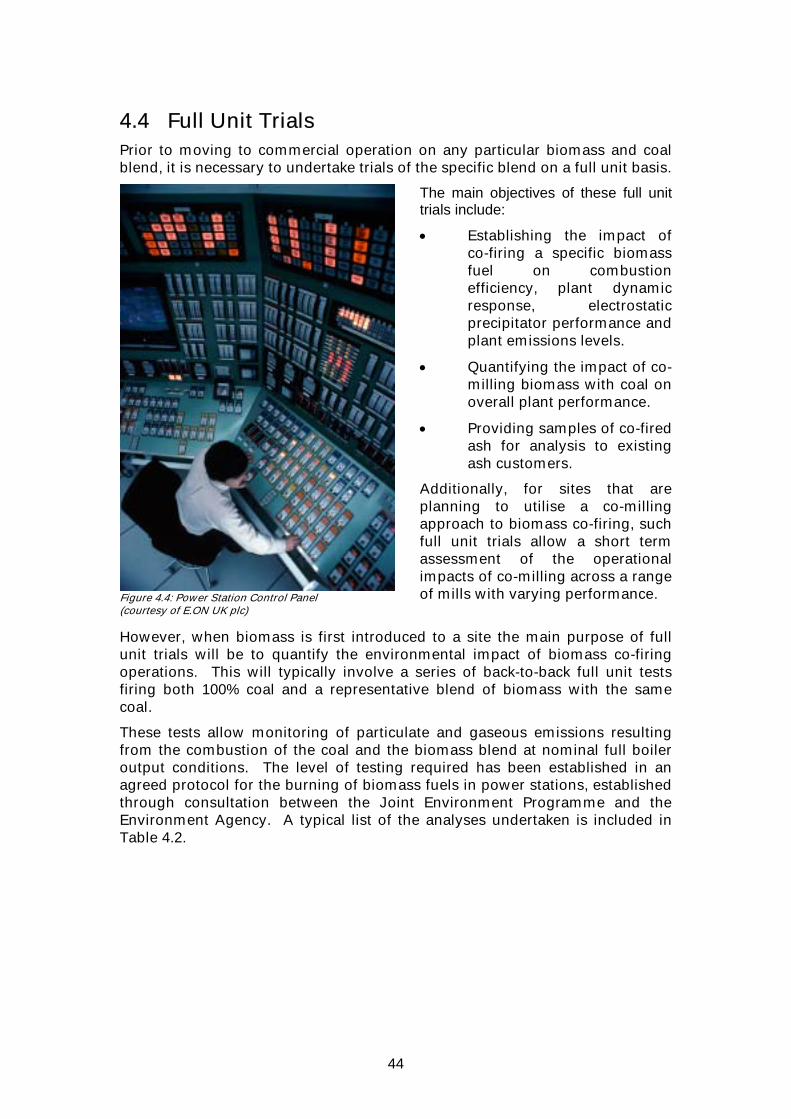
44
4.4 Full Unit Trials Prior to moving to commercial operation on any particular biomass and coal blend, it is necessary to undertake trials of the specific blend on a full unit basis.
Figure 4.4: Power Station Control Panel (courtesy of E.ON UK plc)
The main objectives of these full unit trials include:
• Establishing the impact of co-firing a specific biomass fuel on combustion efficiency, plant dynamic response, electrostatic precipitator performance and plant emissions levels.
• Quantifying the impact of co-milling biomass with coal on overall plant performance.
• Providing samples of co-fired ash for analysis to existing ash customers.
Additionally, for sites that are planning to utilise a co-milling approach to biomass co-firing, such full unit trials allow a short term assessment of the operational impacts of co-milling across a range of mills with varying performance.
However, when biomass is first introduced to a site the main purpose of full unit trials will be to quantify the environmental impact of biomass co-firing operations. This will typically involve a series of back-to-back full unit tests firing both 100% coal and a representative blend of biomass with the same coal.
These tests allow monitoring of particulate and gaseous emissions resulting from the combustion of the coal and the biomass blend at nominal full boiler output conditions. The level of testing required has been established in an agreed protocol for the burning of biomass fuels in power stations, established through consultation between the Joint Environment Programme and the Environment Agency. A typical list of the analyses undertaken is included in Table 4.2.

45
Table 4.2: Assessment Criteria for Environmental Impact Trials ASPECT Consideration
Sulphur dioxide Oxides of nitrogen Hydrogen chloride Hydrogen fluoride Particulate matter (total and PM10) Heavy metals Dioxins and furans Total organic carbon Carbon monoxide
Releases to Air
PAHs Metals Chloride Free chlorine Suspended solids
Releases to Water
pH pH Releases to land Leachability Receipt storage and handling of substitute material Mill performance Burner performance and flame stability Boiler performance and slagging and fouling Electrostatic precipitator performance Ash handling Carbon-in-ash Overall efficiency Plant degradation CEM performance Ash waste status and by-product saleability Odour assessment Review of operating procedures
Other Aspects
Review of BATNEEC/BPEO assessment
The biomass co-firing proportions utilised for these trials will be established from health and safety assessments, experience from other plant, rig testing and (where applicable) previous single mill trials.
On a 500 MWe unit, displacing coal with just 1 wt% of “CO2 neutral” biomass will reduce fossil fuel related CO2 emissions by up to 3 tonnes every hour (depending on the calorific value of the biomass and unit operating conditions). Consequently, with the co-firing ratios that have been achieved on coal-fired plant in the UK, co-firing biomass can make a significant contribution to the Government’s objectives for CO2 reduction. Whilst this is the driver behind the inclusion of biomass as an eligible source of renewable power under the UK
46
Renewables Obligation, it is clearly important that the impact of co-firing biomass on other boiler emissions is properly assessed:
• NOX: Reductions in NOX emissions of up to 10% have been measured when co-firing biomass. Although these reductions have not been achieved with all fuel and plant combinations, NOX emissions levels have never been seen to increase as a result of biomass co-firing. Where reductions have occurred, they have been attributed to the higher volatility of the biomass fuel, which makes the conversion of organically bound nitrogen in the fuel more amenable to control by the air staged low-NOX combustion systems found on most boilers. Biomass fuels would also be expected to burn with a lower adiabatic flame temperature reducing thermal NOX formation rates, although this is likely to be a secondary effect.
• SO2: Calculations based on the analyses of the raw coal and biomass indicate that the relatively low sulphur content of the biomass compared to the coal should result in a reduction in boiler SO2 emissions. Such reductions have not, however, always been observed during environmental impact trials. Whilst the impact on boiler SO2 emissions of co-firing low sulphur content biomass with coal will clearly be positive and can be demonstrated theoretically, in practice the low proportions of biomass being co-fired and resultant small changes in measured emissions are easily outweighed by the heterogeneous nature of coal supplies, and may be difficult to demonstrate. This is particularly true when the biomass is fired in conjunction with relatively low sulphur content coals.
• Carbon-in-Ash: Small increases in carbon-in-ash, of the order of one percentage point, have generally been seen when co-firing biomass. These are in-line with reported co-firing experience from elsewhere and may be attributed to the presence of biomass degrading the grinding performance of the mills. The results of these full unit trials and subsequent commercial operational experience of co-firing biomass suggests that these increases have not been significant enough to represent a longer-term issue for the commercial operation of the plant.
• Particulate Emissions: In some cases particulate emissions have also been seen to increase slightly during co-firing trials. However, given the high collection efficiency of electrostatic precipitators (designed to collect over 99.7% of the inlet dust concentration), the recorded increase in emitted dust levels has represented only a marginal change in performance. In all cases where it has been observed, it has remained within the tolerance band allowed under the particulate emissions monitoring standard for repeat tests at the same condition.
A variety of factors could explain these observed increases in particulate emissions, including variations in the composition of the underlying coal, increased carbon content of the incident dust or the impact of the biomass on ash resistivity, flue gas volumes and dust size distribution. Given the level of change observed and the fact that in all cases dusts emissions were maintained comfortably below the existing particulate emissions limits of 50 mg/Nm3, the impact of co-firing biomass on boiler particulate emissions levels is not considered significant.
• Ash Matrix & Trace Element Analyses: Given the contrasting ash matrix analyses of coal and biomass fuels, some impact on ash matrix and trace element analyses would be expected from co-firing biomass. In many cases

47
this was seen with significantly increased levels of potassium and phosphorous oxides in the co-fired ashes (where these elements were apparent in the raw fuels). However, analyses of the co-fired ashes were still dominated by silica and alumina.
Generally, because biomass contains considerably less trace elements than coal, the overall impact of co-firing biomass with coal is to reduce the input of trace elements into the boiler. Consequently, the concentrations of most of the analysed trace elements in the air heater inlet ash decreased, and those measured in the emitted flue gas showed little impact from co-firing. In most cases the emitted concentrations were the same (within the limits of experimental accuracy) for both the baseline and co-fired cases. Where changes were observed these were generally attributed to changes in the retention of specific elements in the co-fired ash. The exception to this is zinc which is apparent in higher concentrations in most biomass fuels than in coal and is consequently often emitted in higher concentrations when co-firing.
• Dioxins & Furans: Although there are 210 different dioxins and furans that can be formed in combustion processes, it is only 17 of these that are of concern owing to their toxicity, stability and persistence in the environment. Concentrations of dioxin are expressed as a toxic equivalent value (TEQ) which is derived from an analysis of these 17 toxic forms and an assessment of their relative toxicity.
A joint measurement campaign undertaken during 2001 by UK power generators involved the analysis of 13 samples of power station ash materials. The results of these trials indicated a range of 0.05-2.4 ηg/kg TEQ in the dioxin/furan content of power station electrostatic precipitator and furnace bottom ash. These values can be compared to results from an HMIP trials programme which measured dioxin levels in 11 rural soil samples and 5 urban samples. The average dioxin content measured in these samples were 28.37 ηg/kg TEQ and 5.17 ηg/kg TEQ respectively for the urban and rural soils. The dioxin and furan levels measured during environmental impact trials were all close to the limit of detection of the analytical technique used. All the results are at the bottom end of the range previously measured from UK coal fired power stations and there is no evidence of any adverse impact of biomass co-firing on boiler dioxin/furan emissions.
In addition to the testing described above, in many cases a further assessment was made of the environmental impact of co-firing biomass based on the techniques used in each station’s Air Quality Management Plan, and the subsequent Annual Reviews of this plan for the Environment Agency.
These assessments considered the impact that biomass co-firing would have on ground level concentrations of nitrogen dioxide, sulphur dioxide and particulate matter (PM10, particles with a diameter <10µm):
• SO2: Because emission concentrations of SO2 resulting from co-firing biomass would typically be lower than those resulting from coal firing, predicted ground level concentrations of SO2 arising from biomass co-firing are also lower than those resulting from 100% coal firing and will not, therefore, impact on a stations potential to meet relevant air quality standards.

48
Figure 4.5: Eggborough Power Station (courtesy of E.ON UK plc)
• NO2: Predictions of ground level concentrations of NO2 associated with a particular station are generally worst case predictions based on a number of pessimistic assumptions, including the worst case assumption that all emitted nitrogen oxides are in the form of nitrogen dioxide at the point of maximum impact. Since emission concentrations of nitrogen oxides were shown to be either unaffected or to reduce as a result of co-firing with biomass, predicted ground level concentrations of NO2 resulting from biomass co-firing would also be unaffected or show similar reductions.
• Particulate Matter Emissions: Predicted ground level concentrations of PM10 are also based on the worst case assumptions. They assume that all particulate matter emitted is comprised of PM10, i.e. has a diameter less than 10 µm, and that emissions concentrations will be equal to the limit of 50 mg/Nm3.
Since biomass co-firing resulted in no significant changes to particulate emission concentrations, and emissions levels recorded during trials on a number of sites were well within the stack emission limit value of 50mg/Nm3, the ground level concentrations of PM10 predicted for biomass co-firing are similar to those resulting from firing on coal alone.
4.5 Fuel Handling Assessing the bulk handling characteristics of biomass materials used for power generation is difficult for a number of reasons. The type and quality of biomass fired, especially moisture content, can be variable and the biomass is susceptible to biological activity that may influence handling; the biomass may be fibrous and elastic, complicating the measurement of the handling characteristics and invalidating the application of traditional design methods;

49
and particle shape can be variable and is often dependent on upstream processing.
In addition, blending small quantities of one bulk material with another (as happens when biomass is co-milled with coal) can have a significant influence on the properties of the mixture. This has been observed on sites co-milling biomass where, until measures were taken to resolve the issues, mill bunker hang ups were seen to increase when biomass was introduced into the system.
Information about a number of material bulk properties are used for designing bunkers and silos that can discharge reliably under gravity, i.e., without the need for discharge aids. The type of flow regime set up within the bunker (mass or core flow) can also be selected by design. In this respect, wall friction is critically important for obtaining mass flow behaviour, in which all of the material is in motion against the confining walls. Retrofitting smooth liners has proven to be successful in improving the flow behaviour of coal systems and is now being pursued for blends since mass flow is always preferred when handling biomass to avoid biodegradation within the bunker (discussed below).
The physical properties required for such bulk solid characterisation and design work are normally derived from shear cell measurements which tend to be complex, costly and time-consuming. However, shear cell testing is the only proven methodology for bunker design and the associated costs are trivial when compared with the costs arising from handling problems. Despite this, the conventional testing/design approach is inappropriate for some biomass types.
In some circumstances, small amounts of biomass actually improve the flowability of coal since biomass materials are generally hygroscopic, readily absorbing water and reducing surface / free moisture. However, this will also tend to result in more fines being released from the surface of the coal, which is consistent with experience from sites where fuel that has been blended off-site has been received as part of early biomass co-firing trials. In these cases dust blow off was found to be a major concern.
Plant that have been co-milling biomass on a commercial basis for some time have encountered problems with more extreme bunker flow profiles with deposits building up at the bunker walls and bridging at the bunker outlet. Test work has indicated that this experience is likely to be at least partly due to the release of coal fines associated with surface drying of the blend. Moisture content has been found to be the most important parameter affecting these “flowability” characteristics of coal:biomass blends. When blended material becomes trapped closer to the bunker walls, this will tend to increase in strength due to fungal growth, further aggravating the fuel build up. It is generally beneficial to operate bunkers in a ‘mass flow’ mode (all material moving) and this is particularly true for biomass so that the material does not degrade. Bridging is less likely to be a problem in mass flow and this is supported by better operational experience with biomass blends in the mill bunkers that have smooth stainless steel liners that promote such flow regimes.
When neat biomass is considered, in relation to handling systems installed as part of on-site blending schemes, the bulk handling characteristics of the fuels have predominantly been affected by the moisture tolerance of the biomass material. Some materials are very tolerant to water addition and remain relatively free-flowing, whereas some biomass fuels are very intolerant to water
50
addition and become impossible to handle when wet. These differences have been established through shear cell testing and borne out by experience on plant, illustrating that a modest amount of test work can give valuable operational information for new biomass types. However, it should be noted that co-firing experience to date has been limited mostly to relatively free-flowing granular materials. Handling herbaceous (grassy) materials, for example, would be more problematic and would require different handling solutions.
Blending biomass with coal also affects the flow through mills and classifiers. The generally lower volumetric energy density of biomass fuels means that the volumetric flow through the mills increases for the same load. If the station is constrained by mill capacity, this can be a serious problem. The completely different aerodynamic properties of the biomass also affects the performance of the classifiers. Most biomass particles will have a higher drag coefficient and a lower density than coal and, consequently, the mill product quality (as measured by the particle size distribution at classifier outlet) is likely to degrade, with the larger particles being biomass.
4.6 Design Studies There are a large number of plant options available for existing boiler plant operators who wish to implement biomass co-firing. These include levels of modification ranging from the very minor, to major multi-million pound investments. Determining the appropriate technology, and level of modification, for a power plant is a highly site specific process, and depends on the following factors: • Existing plant design • Projected delivered cost and availability of biomass fuel • Projected value of electricity generated from biomass • Biomass consumption target • Biomass fuel type and flexibility • Biomass fuel quality and variability • Operational flexibility requirements • Projected impact on existing plant operations • Environmental considerations • Availability of capital • Space constraints • Projected service life • Future plant modification options
Design studies need to address how biomass will be received on site, stored, prepared and combusted, and should address the practical, economic, operational, and health and safety aspects of these activities. Consideration of these issues, and the multitude of technological solutions which are now available, results in a large matrix of potential options for evaluation. Although there are many established suppliers of the associated equipment, it is difficult for any supplier to offer an objective assessment of the modification options available for a given site. Undertaking a design study, using either internal resources, or independent technical consultancies, enables the operator to identify suitable modification options and to understand the likely costs and

51
implications of these, including the impact on existing plant operation and maintenance activities.
The undertaking of a design study increases knowledge of co-firing processes and technology amongst the plant operators own staff, and provides a sound basis for the development of a contract enquiry document and specification. Once the enquiry has been prepared and issued, the design study provides valuable information to support the tender assessment process. The design study is an established route to an impartial selection of technology type, assessment of practicality and cost impact, and as a result a valuable means to reduce commercial risk.
Typically a design study would be undertaken as an interactive process. The requirements of the site operator need to be defined clearly at the outset to ensure that the initial options review is driven by the core needs of the end user. This generally allows an initial array of options to be reduced progressively to two or three major schemes for more detailed analysis. It is important at this stage to obtain feedback and input from the plant operator to ensure that preferences or concerns can be taken into account in the review. Once a lead option has been identified, together with outline conceptual design and costing, a decision needs to be taken to either produce more detailed conceptual design work or to progress to specification and issue of a contract enquiry. An outline of such a process is shown Figure 4.6.
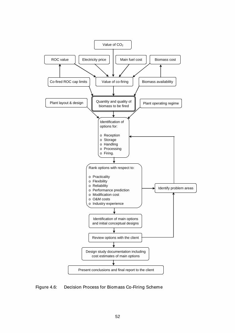
52
Figure 4.6: Decision Process for Biomass Co-Firing Scheme
Biomass costMain fuel costROC value Electricity price
Biomass availabilityValue of co-firing
Quantity and quality of biomass to be fired
Co-fired ROC cap limits
Value of CO2
Plant operating regime Plant layout & design
Identify problem areas
Identification ofoptions for:
o Receptiono Storageo Handlingo Processingo Firing.
Rank options with respect to:
o Practicalityo Flexibilityo Reliabilityo Performance predictiono Modification costo O&M costso Industry experience
Identification of main options and initial conceptual designs
Review options with the client
Design study documentation includingcost estimates of main options
Present conclusions and final report to the client

53
The modification of plant in the UK for biomass co-firing is a relatively new and progressive business. As a result, suppliers and users alike are learning from their own and others experiences. In such an environment cost estimation is not precise and at the design study stage cost estimates should be used for guidance only. Final costs will be highly dependent on the contractor selected and their experience and approach to the implementation of the project. Due to the nature of the co-firing business, the variety of plant and fuels available, most projects will be bespoke solutions even if they employ a number of standard components.
4.7 Plant Specification
Figure 4.7: Biomass Storage Silo (courtesy of E.ON UK plc)
The specification of plant and equipment for the co-firing of biomass is a similar process to that of specifying any other electro-mechanical process system. The basic functional requirements of the plant need to be defined clearly together with the context in which the new equipment will be used, and the fuels to be fired. The key aspects of the plant operational performance should be subject to performance guarantees. Such guarantees might include: • Maximum continuous throughput
under stable conditions • Minimum continuous throughput
under stable conditions • Site services requirements (e.g.
consumption of works power) • Impact of biomass combustion on
the existing plant integrity and environmental emissions
• Reliability and longevity of equipment
These may be supported by damages associated with ensuring the completion of installation and commissioning activities in accordance with the timescales required by the purchaser.
The specification of the plant should be such as to ensure that the tender addresses the safety and integrity of both the new and existing plant. The standards to which the new equipment complies should be clarified. Of particular relevance to new fuel firing equipment is to ensure that adequate control and protection systems are included to ensure the safe preparation, transportation, and combustion of the fuel. Full account needs to be taken of how such a system will interface with the existing plant, control, and protection systems to ensure safety under all normal and abnormal operating conditions. New plant should be designed to be compliant with the Dangerous Substances and Explosive Atmospheres Regulations (DSEAR) and incorporate suitably

54
rated components. Specifically, the tenderer must state how the creation of potentially explosive conditions will be avoided. Fuel handling and storage facilities should be equipped with fire detection and protection equipment.
Given the range of potential solutions to a functional co-firing enquiry document the specification should request a full description of the plant and equipment to be used, how it will operate and how it should be maintained. Schedules of recommended spares together with maintenance schedules for the first 5 years of operation would typically be required to provide an early indication of the integrity and reliability of the system.
Many potential suppliers will have little experience of the type of solution required on a specific plant. The purchaser will need to request sufficient information and references to provide confidence that the potential supplier is competent to engineer a solution which will meet the requirements of the contract, and that any problems which may arise will be resolved quickly. There are very few organisations that will be capable of supplying all the component parts of a co-firing system from within their own organisations, and therefore many components will be sub-contracted to third parties. The enquiry document should recognise this, and ensure that the extent of sub-contracting and bought in equipment is disclosed.

55
5. TECHNOLOGIES USED FOR BIOMASS CO-FIRING
5.1 Fuel Blending Alternatives Where biomass is to be co-milled rather than being co-fired via a direct injection route, on-site blending of coal and biomass has generally been applied. The objective of this has been to provide a reasonable distribution of the biomass within the bulk coal supply, rather than to provide a fully homogeneous ‘blended’ fuel. This is important to avoid operational transients due to sudden fuel quality changes, to ensure control of the properties of the bulk fuel within safe limits, and to avoid problems with loss of mill coal flow.
Power station operational requirements favour the use of continuous fuel delivery systems. Biomass is less stable than coal, i.e. it degrades when exposed to air and/or moisture. Hence, techniques such as layering with coal on a stockpile cannot be employed unless the fuel is reclaimed and fired within a short time period, and although these techniques have been used as part of co-firing operations in other countries, they have not been used in the UK.
For all practical purposes, mixing after storage has been the preferred method of fuel blending. In this regard the ideal location is mixing at or slightly downstream of the coal feeder. The feeder meters the primary fuel (coal) and the biomass could be transferred into this stream using a screw conveyor. A screw conveyor allows some degree of control of the process but more importantly it allows the biomass storage system to be segregated from the milling plant which must be capable of withstanding pressurisation. A screw conveyor also gives a quick response to a trip signal.
The majority of biomass co-firing retrofits in the UK have not adopted this method because it requires duplication of the coal handling and storage systems employed for the primary fuel. Instead, biomass is introduced to the primary fuel conveyor route and transported to the main bunkers prior to firing. Hence mixing occurs either on a conveyor or in a transfer chute, i.e. continuous mixing on route to the boiler plant.
Control of such mixing processes has not been straight forward. For relatively low flow rates, screw conveyors have been used to control the flow, with the biomass transfer rate being determined by virtue of the screw speed. This can, however, be misleading due to possible voids in the screw when operating. When mixing large quantities of biomass (greater than 5% by weight), for control purposes it has been possible to infer the biomass/coal ratio using well calibrated belt weighers (i.e. within 1%). Even this approach only gives an approximate indication and auditing of biomass burn rates (and associated heat input) has to date generally been undertaken on the basis of longer term measurements of fuel burn based on more accurate measurements of fuel stocks, weigh bridge tickets and fuel analysis.
The mixing of similar materials with continuous systems can be problematic, since controlling the flow of both streams to merge successfully without spillage or dust clouds requires careful design and operation. The mixing of dissimilar materials, with differing densities, particle sizes and size distributions, is even more prone to such problems. Add to this the inherent

56
passage of turbulent air around the material being transferred and the vulnerability to spillage and dust clouds can increase to the point where dust control or recovery systems (e.g. dust extraction or spillage systems) need to be installed to cope with them.
Early co-firing operations in the UK have shown that the use of existing coal chutes and conveyor belts for biomass transfer and blending is problematic with regard to spillage and dust, particularly at the point where the biomass is first mixed with the coal. The extent of such problems is, however, a function of fuel type (both coal and biomass) and plant design.
Figure 5.1: Biomass Dust Accumulation (courtesy of E.ON UK plc)
Where biomass has been introduced to the system via a coal chute the turbulent airflow, which can be in the reverse direction to the coal flow, causes the finer biomass and coal particles to form clouds which fill the chute and are dragged down with the coal/biomass mix. This effect can be worsened when the mixture strikes the conveyor belt adding to the resultant dust cloud. Efforts have been made to contain the problem by adding enclosures, upgrading the skirting between the chute and conveyor, or extending the hood of the chute along the conveyor belt. Although these enhancements have reduced fugitive dust emission, in some cases the improvements have been limited and the modifications make maintenance access more difficult.
The problem of dust may not be confined to the first chute. Downstream transition points may also generate dust clouds. It depends on whether the moisture in the coal transferred to the biomass is sufficient to dampen down the dust effect. Generally it has been shown that after two or three transfer points the dust is probably no worse than with coal alone.
Blending the fuels by placing the biomass on the belt upstream of the coal can produce similar problems, the coal tends to strike the biomass already on the

57
belt, and for some biomass types this may cause spillages and dust clouds due to the coal’s higher density and particle size.
Another method that has been utilised is to sprinkle the biomass on top of the coal on the belt, this gives less potential for dust generation particularly if the system can be arranged such that the direction and velocity of the biomass particles are similar to that of the coal prior to deposition.
The most pragmatic solution using the existing coal conveyors and chutes is likely to be minimisation of the dust clouds generated coupled with dust suppression, containment or extraction equipment.
The minimisation of dust clouds in the chute can be achieved by avoiding the passage of air in the reverse direction to the coal. The down flow of coal in a chute almost always causes air to circulate back, thereby causing eddy currents at the interface. These stimulate the generation of clouds from any dust present in the biomass, some of which is dragged with the coal. If the air is pulled downwards at the same velocity as the coal, the effect will be reduced. This can be achieved by using a hood extending from the chute along the conveyor for a significant distance and a large extraction system to pull the air and entrained dust through the system. The length of the hood and quantity of air moved is system dependant but lengths of less than 10m should not be used as this gives only a few seconds settling time with normal conveyor belt speeds.
5.2 Biomass Bulk Handling Plant With regard to the design of mechanical, gravity flow and pneumatic handling systems, the most important properties of powders or bulk materials are considered to be:
• Bulk density • Particle size distribution • Moisture content • Abrasiveness • Angle of repose
However, biomasses add further properties such as:
• Combustibility • Explosion severity • Flammability • Thermal properties • Hygiene • Toxicity.
Knowing what biomass materials the plant is to be designed for is, therefore, extremely important.
Current methods of bulk handling biomass for co-firing are primarily road transport, small stockpiles (covered and open), silos, screw and belt conveyors. Larger delivery systems to the power station such as trains and barges have yet to be employed, but in principle they can be used with specific measures.
Generators have typically experienced biomasses such as sawdust, wood pellets, palm kernel expeller (PKE), olive residues, and cereal pellets. In all of the above cases, there is a tendency to handle these products undercover for
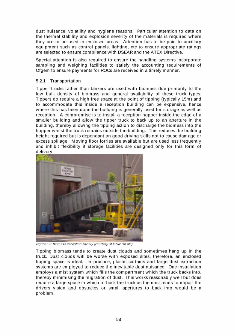
58
dust nuisance, volatility and hygiene reasons. Particular attention to data on the thermal stability and explosion severity of the materials is required where they are to be used in enclosed areas. Attention has to be paid to ancillary equipment such as control panels, lighting, etc to ensure appropriate ratings are selected to ensure compliance with DSEAR and the ATEX Directive.
Special attention is also required to ensure the handling systems incorporate sampling and weighing facilities to satisfy the accounting requirements of Ofgem to ensure payments for ROCs are received in a timely manner. 5.2.1 Transportation
Tipper trucks rather than tankers are used with biomass due primarily to the low bulk density of biomass and general availability of these truck types. Tippers do require a high free space at the point of tipping (typically 15m) and to accommodate this inside a reception building can be expensive, hence where this has been done the building is generally used for storage as well as reception. A compromise is to install a reception hopper inside the edge of a smaller building and allow the tipper truck to back up to an aperture in the building, thereby allowing the tipping action to discharge the biomass into the hopper whilst the truck remains outside the building. This reduces the building height required but is dependant on good driving skills not to cause damage or excess spillage. Moving floor lorries are available but are used less frequently and inhibit flexibility if storage facilities are designed only for this form of delivery.
Figure 5.2: Biomass Reception Facility (courtesy of E.ON UK plc)
Tipping biomass tends to create dust clouds and sometimes hang up in the truck. Dust clouds will be worse with exposed sites, therefore, an enclosed tipping space is ideal. In practice, plastic curtains and large dust extraction systems are employed to reduce the inevitable dust nuisance. One installation employs a mist system which fills the compartment which the truck backs into, thereby minimising the migration of dust. This works reasonably well but does require a large space in which to back the truck as the mist tends to impair the drivers vision and obstacles or small apertures to back into would be a problem.

59
Remnant material in tipper trucks may be a problem if the contractor requires a clean truck for the return journey (i.e. prior to collecting another cargo). Although not a major problem the cleaning of the truck may impair access by other vehicles, or a special cleaning area needs to be provided. Rumble strips can aid cleaning. These would be placed such that when the truck is empty it could be driven over them to a cleaning area where the truck is tipped again to empty all the contents. Generally the need for these measures is avoided by using dedicated vehicles or trucks in good condition (i.e. no damage to the internal surface of the truck hopper). 5.2.2 Reception Hoppers
The reception hopper should have a grid to capture oversize material. Where possible, this should be sized to prevent the passage of any material which might interfere with the operation of downstream plant.
Problems have been encountered when hoppers feed directly onto a belt conveyor, the natural tendency of the belt is to compact the material as it moves under the hopper throat causing the uneven flow of material in the hopper and high shear forces (possibly tripping the motor). This can be overcome by using an apron feeder hopper or installing wedge shaped guides plates in the hopper bottom to allow the aperture to expand as the conveyor progresses.
Belt conveyors or more commonly bucket elevators can be used from the reception hopper discharge screw to the storage device. As with screw conveyors the main problem will be vulnerability to tramp material (scrap metal) entering the bucket mechanism and causing a jam. 5.2.3 Storage Devices
The capacity for large scale, long-term storage of biomass has not generally been constructed on power stations co-firing biomass in the UK. Currently installed systems provide up to 7 days worth of buffer storage, in most cases utilising a 5 or 6 day delivery schedule. The storage methods used include open and covered piles, enclosed bunkers, and silos. Open piles were used for early trials work and have been largely superseded. The type and size of biomass storage has varied from longitudinal portal frame buildings to silos. The choice is often a compromise between the size of delivery, the biomass to be accommodated, the frequency of delivery, environmental dust nuisance, and health issues. 5.2.4 Bunkers
The bunkering systems that have been utilised comprise either a simple enclosure for use with mobile plant or pusher floor, or a dedicated silo with top filling and active discharge system. The choice is dictated by cost, strategic and environmental issues.
An enclosed bunker with pusher floor inside a dedicated building gives considerable flexibility in operation. Biomass can be tipped in selected areas of the floor such that operation is not restricted to first-in, first–out as would be the case with a silo. It also allows sampling and thermal probing of the pile relatively easily. With a moving floor it can, in theory, be left to discharge itself. However, the need to monitor the pile profile and the need for cleaning means that these facilities are unlikely to be unmanned. Maximum pile heights to

60
avoid the risk of self-heating are in the region 4 to 12m depending on the biomass composition.
An interesting alternative to bunker storage is a flat back re-claimer. To use a system of this type only requires a flat concrete surface, on which a low profile chain or screw conveyor is placed with its end section inclined. This allows material piled on top of the chain conveyor to be dragged under the pile towards the discharge. This type of equipment can be positioned adjacent to belt conveyors and is easily complimented with a second feed to the same belt. It is relatively expensive but very versatile.
With open bunkers the environmental issues, particularly dust and spores, should be addressed. Respirable dust limits should be adhered to and a determination made as to the possibility of spore generation (particularly with wood and cereal products).
5.2.5 Silos
Silos can be substantially automated to give a good flow of biomass, provided the handling characteristics of the biomass are recognised. This should include an assessment of material fines. These occur in most biomasses, of particular note are the fines associated with breakdown of pellets, particularly when significant amounts of moisture are present. Shear cell testing is advised for the purpose of confirming the silo design, in particular the discharge shape and whether active discharge methods are necessary.
5.2.6 Active discharge aids
With the highly variable nature of biomass and the difficulty of measuring the handling index, it is good practice to include active discharge aids to bunkers and silos. These can take the form of rotary screws, rotary feeders or sliding frames with flat bottom silos, or shakers and rotary valves with cone shaped silos. There may be a case for steep sided silos to promote ‘mass flow’ of the biomass, the disadvantage being the additional height of the silo.
Figure 5.3: Biomass Silo Discharge (courtesy of E.ON UK plc)

61
5.3 Fuel Preparation Alternatives With the co-firing of biomass, the fuel preparation alternatives are primarily associated with separation. That is, removal of grossly oversize material (not suitable for conveying or milling) and possibly moisture.
Screening is used to separate coarse and oversize material, and can be completed in two stages: large objects can be removed by the reception hopper grid, and smaller items using either a moving screen or even a cyclone. The latter would mean the transition to a pneumatic system for handling possibly between the reception hopper and the silo. This has not been attempted with biomass in the UK as yet, although it will be of interest where pneumatic transport technology is used for the direct firing of biomass.
There are a number of reasons for preparing and understanding the production techniques of biomass fuel for combustion.
One common generator target is to reduce the moisture content of the biomass. High moisture content in a fuel adversely effects the efficiency of the combustion system. The moisture content of biomasses varies significantly. Fresh wood can be over 50 wt% moisture whereas the moisture content of waste wood or straw is often below 15 wt%.
Natural drying can be effective in reducing moisture content (particularly of freshly cut timber); however, it is dependent to some extent on environmental conditions. If woodchips are stored in a pile, the temperature in the pile will increase due to biological degradation effects. The heat produced by the micro-organisms causes a natural convection process. Consequently, the fuel in the centre dries whereas the vapour will pass to the cooler zones of the pile. For the production of pellets or briquettes, the moisture content of the raw material must be about 15 wt%. The large scale drying of biomass has not been undertaken in the UK as yet. However, some materials have been pre-dried before firing in power stations.
The weathering of some crops can also be beneficial for the removal of contamination by soil, or by the leaching of water soluble elements such as potassium and chlorine.
5.4 Modifications to Existing Plant Few plant modifications are required in order to co-mill solid biomass fuels with coal. The major changes needed for such an approach to biomass utilisation are procedural to ensure that the processing of the biomass fuel takes place in a safe and controlled manner.
Reception and dosing (or blending) equipment can be arranged relatively simply utilising readily available “agricultural” equipment. Although such systems have been effective, they can generally only provide relatively low capacities with limited storage volumes.

62
Figure 5.4: Batch Blending Operations During Biomass Trials (courtesy of E.ON UK plc)
Figure 5.5: Temporary Blending Plant (courtesy of E.ON UK plc)
Handling costs have been relatively high for these approaches, and on larger plant with requirements for higher biomass proportions they have led to significant fugitive dust emissions and poor blend quality, with associated implications for plant operation. Consequently, these arrangements have typically been reserved for small plants or for demonstration purposes only.

63
Figure 5.6: Biomass Handling Plant (courtesy of E.ON UK plc)
For larger scale commercial operations additional purpose designed reception, storage, and handling equipment is required. Typically this will require the installation of new equipment in a convenient location incorporating vehicle access, an unloading area, a storage silo, and a means of introducing the fuel into the existing raw fuel system.

64
Typical modifications involved when co-firing biomass by dosing into the fuel system include:
• Determination of appropriate interface to existing coal conveying system. • Assessment of additional loads on existing structures. • Integration of the new plant into the existing conveying system start up,
shut down and tripping sequences. • Determination of a flexible control scheme to accommodate the range of
materials to be fired. • Determination of appropriate power supplies. • Review of the safety aspects associated with increased mobile plant/vehicle
access. • Review of the suitability of good housekeeping practices due to the
differences in the characteristics of biomass compared to coal. • Review of safety related fuel and combustion plant operational procedures.
If the biomass fuel is to be kept separate from the main fuel until the point where it is burned in the boiler, then the plant modifications required are significant. Not only is new front end equipment required for reception and storage, but the fuel will require a means of controlled transport to the boiler, possibly with a means of processing the stored fuel, along with an effective means of introduction into the furnace which ensures acceptable combustion performance.
Such modifications can take many forms and the most appropriate approach for a particular application needs to be determined on a site specific basis. Since the new equipment will be installed around existing plant, which may already have been extended, additional modifications to instrumentation and control systems will be required to ensure its safe and effective operation. It is also likely to require further mechanical support, cabling and power supplies. The new equipment will need to be added to plant information systems and maintenance procedures, with appropriate spares included in stores inventories.
Typical modifications when direct firing include:
• Interfacing with existing boiler controls, interlocks and permissives. • Boiler tube and casing modifications. • Safety isolation requirements. • Supply of burner combustion and cooling air. • Interfaces with instrument air supplies. • Relocation of walkways. • Interfaces with power supplies. • Assessment of additional loads on existing structures and suitable thermal
expansion arrangements. • Review of the safety aspects associated with increased mobile plant/vehicle
access. • Review of safety related fuel and combustion plant operational procedures.
The installation of new plant and equipment requires space, not only for the equipment itself but for access for operational and maintenance purposes. In many cases new access gantries or platforms may be required or existing equipment may need to be moved to ensure adequate access after installation.

65
It is particularly important that detailed consideration is given to the location of any new burner installations to the furnace. Not only are such modifications costly but they have the potential to adversely affect the performance and integrity of the boiler. Any plant modification to introduce biomass fuels into an existing combustor should be subject to professional scrutiny and be risk assessed. Although the co-firing of biomass fuel is simple in principle, great care is needed in practice to ensure that modified plant is safe, reliable, and effective.
5.5 Dedicated Burners / Injectors The use of separate burners in existing boilers and furnaces for the firing of biomass fuels is highly advantageous where significant quantities of biofuels are to be fired over a period of more than a few years. Blending biomass fuels with main fuels can cause problems with handling, stability, and processing. In the case of solid biomass and coal, co-milling adversely impacts coal mill capacity and performance and can lead to control difficulties. Dedicated firing systems benefit by improving flexibility whilst preserving the performance of the existing equipment. Additionally, the potential capacity of direct firing systems is higher than for co-processing and is restricted in part by the availability of sufficient biomass fuel.
Biomass fuels are generally low ash, high volatile, and have a moisture content that is dependant on their type and pre-treatment. When exposed to a coal fired furnace environment a finely divided biomass material will rapidly heat, release excess moisture, and devolatilise leaving only a small quantity of residue. Since the volatile content of biofuels is high, and any intermediate chars are reactive compared to coal, burnout under similar conditions is much better for biomass than for coal. Due to this, and the practicality and energy required for size reduction, biomass is usually fired as a pulverised fuel stream with a relatively coarse size distribution. If the particle size becomes too coarse, however, the trajectories of the particles and the residence time available for drying and combustion become limiting factors. There is therefore an optimum particle size range for a biofuel which allows good combustion without requiring excessive fuel processing. The design of the burner and its location in the furnace will determine to a large extent where this cut off point is.
Biomass burners range from simple pneumatic injection orifices through swirl stabilised register burners to external combustors. Where simple pneumatic injection equipment is utilised it is recommended that this is interlocked with the existing firing system, and is restricted to locations where any fuel injected into the furnace must pass through a high temperature turbulent zone where it will be ignited before it can exit the main burner zone. The selection of appropriate technology will depend to a large extent on the fuel properties, the existing plant design and the firing capacity requirements. Some plants have modified existing burners to accept biomass as a separate fuel stream within the same assembly. Although this appears to have been successful, there is a large degree of interaction between the main and supplementary fuel which is not always advantageous.
Although there are many organisations who supply small biomass burners for various process heat applications, there are few suppliers with commercial designs for large biomass burners of the capacity typically used for coal in

66
utility boiler plant. Fortunately, since biomass co-firing proportions are typically low, there is little need at present for burners with a capacity of more than about 25MW thermal. Unlike coal burners, however, there is relatively little experience of applying this kind of burner in a utility boiler environment on the range of biomass materials currently available.
There are a large number of factors which need to be considered in parallel to determine the optimum balance of cost and risk when identifying suitable locations for new biomass burners. These factors need to address not only the practicality of installation but the probability of achieving acceptable trouble free operation in the longer term. On one hand the introduction of new burners can be exploited to improve existing shortfalls in the design of the boiler, but a poorly designed modification can result in substantial operational problems. In the case of a retrofit application there is inevitably a balance to be struck between risk, practicality, capital cost and performance. Factors for consideration when determining appropriate location include the following:
• Physical installation constraints: - Physical space required for installation - Extent of local modifications required for access - Adequate structural support - Ease of general plant area access - Furnace geometry and residence times - Existing burner design and firing arrangement - Burner quarl requirements
• Impact on plant performance: - NOX production and control - Unburned carbon in fly and bottom ash - Distortion of existing furnace heat release profiles - Ash characteristics, deposition, fouling and corrosion - Boiler turndown effects and stability - Biomass burner turndown
Computational fluid dynamics (CFD) modelling activities are helpful in assessing the potential impacts of the installation of dedicated biomass burners to an existing furnace. Although these are capable of highlighting potential problems, they require careful construction and interpretation, and experience and empirical testing plays a large part in assessing the true impact of such boiler modifications.
Direct injection systems may offer an opportunity to some plant operators to increase the total thermal input to the boiler or to replace thermal input lost from the main combustion system due to other factors. The firing of some low sulphur coals can cause a fuel system de-rating which might be recovered by additional biomass firing through a direct injection system. The ability to overfire the boiler in order to generate additional load will depend on ensuring the integrity of the plant for that mode of operation. It will also depend on the rating and spare capacity in the associated turbo-generator.

67
Figure 5.7: Ratcliffe Power Station (courtesy of E.ON UK plc)
5.6 Liquid Biofuels Equipment Liquid biofuels in the UK have to date been limited to use on coal fired power plant, usually as a direct heavy fuel oil replacement. Schemes have been put forward using dedicated additional liquid fuel injectors for such fuels, although complexity and economics have so far reduced the attractiveness of such schemes.
Liquid fuel burners are deployed on coal fired power plant to carry out the following functions:
• Warm up furnace from cold • Provide a source of ignition for initial coal light up and shut down • Provide a stable source of ignition during periods of potential or actual
furnace instability
Liquid burner equipment and systems have been developed over many years to fulfil these requirements in a safe and reliable manner with a wide operational margin. As such, the existing burners themselves can be adapted quite easily to burning a wider range of liquid fuels provided that the fuel can be presented to the burner at the correct conditions for combustion. Where problems are encountered these are usually associated with fuel handling equipment and burner monitoring systems rather than the burner itself.
Most high calorific value liquid biofuels are very good fuels and are suitable for use in boiler applications with relatively little modification. In general, they can

68
be transported and handled easily provided their properties have been assessed, and they can be atomised, ignited and combusted cleanly. Relatively small differences in viscosity, calorific value and density from the existing fuel oils may have a minor impact on the pressure/flow relationships within the fuel system and burner equipment, however these are generally considerations for optimisation rather than for feasibility. The extent of modification to plant and procedures will also depend to a large extent on the original system design fuel and the manner in which the new fuel is to be utilised.
Existing control systems, especially safety related control systems and instrumentation, will require detailed evaluation. Flame monitor systems in particular have caused problems in the past as these are designed to detect a specific oil flame and discriminate this from other flames in the furnace. As such the sensitivity and positioning of these detectors may need to be modified to suit modified flame characteristics.
As with solid biofuels there are a number of options for the introduction of liquid biofuel to an existing boiler which might include:
• Blending of biofuel with existing liquid fuel • Addition of separate fuel injection equipment • Installation of additional register burners • Conversion of a proportion of the existing burners • Conversion of the whole existing liquid fuel system
Blending biofuels with existing liquid fuels is an attractive means of utilisation, but has a number of potential technical pitfalls, including risks of separation and sedimentation.
The addition of relatively simple additional liquid biofuel injection equipment is acceptable, provided that the furnace environment is such that the injected fuel can be burned cleanly and reliably. Since there are few instances where this can be achieved, this is also not considered a preferred option unless capacities are low.
The installation of new burners with a separate fuel supply system is attractive when considering flexibility but is relatively costly. New burners require significant modifications to electrical and control systems, as well as to the boiler mechanical parts, and raise potential concerns regarding the effect on the flow regimes and heat distribution within the furnace. Conversion of an entire fuel system to liquid biofuel is a sound approach but has some inherent risks. If the conversion is significant in terms of time or cost then the fuel supply needs to be reliable and consistent to justify it. Some teething problems and contamination of the fuel system with previous liquid fuels are inevitable. Only once commercial operation has commenced will the real operational difficulties become apparent. Such problems may include deposit formation, emulsification, formation of tars, waxes and varnishes, corrosion in the system or degradation of seal materials. Although there are tests and assessment procedures available to guard against such eventualities, there is relatively little UK experience in the firing of liquid biofuels in fuel systems designed for mineral fuel oils. However, the international experience gained of operating conventional fuel oil systems with liquid biofuels has been transferred to two large plant operating in the UK.
The uncertainties regarding the cost and supply of liquid biofuels in the future suggest that partial fuel system conversions are a good compromise between

69
capacity and flexibility. Relatively simple modifications can be made to fuel systems to section off a number of burners for biomass only use, while retaining the original fuel capability.
As with solid biofuels additional equipment is generally required to cover the reception, storage, and transfer of the liquid biofuel to the boiler. For large scale use new storage tank costs can be significant and these may require heating and insulation to maintain fuel quality, in addition to bunding for environmental protection, and fire protection for safety. For smaller capacities, and particularly where fuel flexibility is provided, just in time deliveries or smaller temporary storage facilities may be adequate. New strainers, fuel pumps, heaters, flowmeters and instrumentation would be required in the case of additional burners or a sectioned system. For existing systems the temperature/viscosity characteristics of the biofuel together with its corrosion potential will need to be confirmed for use with the existing plant to avoid fuel degradation and potential plant damage. As with all plant and equipment, the fuels used in practice need to conform to the design fuel properties, and fuel quality monitoring and consistency is an important consideration in achieving optimum performance.
70
6. HEALTH & SAFETY 6.1 Health & Safety Reviews Fuels with a high volatile matter content such as biomass are often liable to storage, milling and PF transport problems arising from an increased tendency for spontaneous combustion, and the use of high volatile biomass fuels in UK power plant has the potential to lead to a major safety incident if not managed correctly.
Consequently, detailed health and safety reviews have been undertaken at each site prior to co-firing biomass, and these reviews have been updated in light of commercial experience of these operations.
For a fuel/air mixture, a deflagration cannot propagate if the mixture ratio is too fuel rich (upper explosive limit) or too fuel lean (lower explosive limit). For a coal dust/air mixture the lower explosive limit ranges from around 30 g/m3 for lignites to around 140 g/m3 for a low volatile coal. Lower explosive limits typically quoted for biomass fuels are similar to those quoted for lignites (30-40 g/m3).
Given a sufficiently energetic source of ignition, the concept of a fuel-rich upper explosive limit for any PF milling system using air as the transport medium is questionable. It has been suggested that, even in the fuel rich region, PF particles can use the air available to continue to react.
It is, however, generally accepted that, for bituminous coals, limiting the air to fuel ratio within the PF supply system significantly reduces the risk of a deflagration occurring. Based on empirical data, supported by some laboratory testing, it has been found that applying similar operating restrictions should not pose any additional threat during normal operation when co-milling biomass, provided that blend concentrations are kept within defined limits.
However, on a mill that has no inerting, more hazardous mixtures, i.e. air fuel ratios above normal operational levels, cannot be avoided during mill start up and shutdown, and certain abnormal mill operating conditions. The typical running regimes on power plant in the UK mean that a large number of mill start-up and shut-down operations are undertaken, leading to high incidence of potentially hazardous fuel and air mixtures being encountered on the mills.
When milling bituminous coals using air swept milling plant which is not equipped with the capability for inerting the transport medium, the acceptable volatile matter limit for the fuel is generally considered to be 45 wt% on a “dry ash free” (DAF) basis. On the basis of laboratory test work, a similar limit has been proposed for the “effective” volatile matter content for biomass/coal blends, provided the biomass content of the blend is kept below 15 wt%.
Explosion severity testing has shown that, across the typical operational dust concentration, the explosion characteristics of biomass/coal blends containing up to 15 wt% biomass are dominated by the blend coal. This view is supported by empirical evidence from short-term closely monitored tests, which suggest that biomass can be safely co-milled, even with relatively reactive coals, at these blend proportions without apparent adverse impacts on mill safety. Therefore, it is considered that the current operational guidelines, with respect to milling system air:fuel ratios applied for coal, are also applicable to

71
biomass:coal blends containing up to 15 wt%, provided that the 45 wt% daf volatile matter limit is observed and mill operating temperature constraints are also applied.
Inerting should be considered for commercial operation with biomass:coal blends containing over 15 wt% biomass or effective volatile matter contents above 45% daf. Limiting oxygen concentrations quoted in the literature for biomass fuels are typically in the range 10 to 14% by volume. Where inert atmospheres are required (in storage silo inerting or as a carrier medium in lean phase conveying systems) it is recommended that oxygen concentrations are maintained below 10%.
Blending biomass fuels, even in small proportions, with coal is known to significantly reduce the ignition temperature of the blend. Addition of 10 wt%
biomass to bituminous coal has been found to reduce the minimum ignition temperature by circa 50°C.
Laboratory testing has shown that ignition energies for biomass fuels are significantly (as much as two orders of magnitude) lower than those measured for typical coals. Therefore the potential for these fuels to be ignited by sparks in a mill, for instance, is uncertain but is appreciably higher than for typical bituminous coals.
The ignition energy for deflagrations within PF supply systems can also be supplied from fuel fed to the mill which is already burning as a result of spontaneous combustion occurring within the coal bunker, and from smouldering fuel deposits formed in hideouts in the mill and air belt, or around blockages caused by tramp material (particularly in classifiers).
Operational co-milling experience with biomass fuels has shown an increased tendency for the mill to reject and for these rejects to ignite. There is also evidence of a tendency for biomass material to concentrate in the mill body. On this basis, and given the lower ignition energies of biomass materials, most plant that have co-milled biomass have applied additional mill temperature limitations as part of their operating regimes.
On the basis of the above work, site specific risk assessments should take into account the various issues likely to result in modifications to the station’s standard operational practices for commercial co-firing operations. Where the biomass is to be co-milled appropriate restrictions on the mill operating envelope should also be considered.
Biomass fuels typically have volatile matter yields of around 80 wt% (DAF) compared with <45 wt% (DAF) for coal, combined with lower ash contents, this results in a higher flame speed for biomass fuels. For practical application, the predicted flame speed should be compared to the existing fuel systems’ minimum transport velocities, particularly during purging following mill shutdown. Many biomass fuels have a flame speed hazardously close to, or greater than, the air velocities of existing pneumatic transfer systems, making them unsuitable for direct use and should be blended to modify their properties. Dedicated biomass firing systems operating with 100% biomass will require inerting or higher transport air velocities, to remove the risk of a flame propagating through the fuel transport system.
To prevent the self heating and possible subsequent spontaneous combustion of biomass, the material should be stored in stockpiles less than approx 4m high. It would be prudent to periodically measure the temperature of any

72
stocks of unfamiliar fuels to enable their self heating characteristics to be determined.
Due to the higher reactivity, lower ignition energy requirements and greater risk of spontaneous combustion within the fuel feed bunker when co-milling biomass fuels blended with coal, there is a greater risk that where loss of coal on a mill results in a bunker blow back this will also lead to combustion of the dust cloud generated within the bunker house.
In view of the nature of the materials being processed, it is recognised that incidents may occur on coal milling plant despite implementing all practicable safety measures. To minimise the risk to personnel and plant, PF supply systems are generally designed to be resistant to the effects of fires and deflagration and to contain credible explosion pressures within the system, and additional safety systems are put in place to protect plant personnel in the event of an incident. Prior to co-milling biomass it is recommended that the current status of these systems is checked to ensure that they will still achieve their design intent.
6.2 Dust and Biological Hazards 6.2.1 Dust
The repeated or rough handling of biomass materials can liberate significant quantities of dust. Dry biomass particles tend to have a low density and large drag coefficient and are easily suspended in air. Generally, the greatest risk posed by biomass to personnel is the exposure to dust, primarily through inhalation.
The Control of Substances Hazardous to Health (COSHH) regulations require that personnel are not unnecessarily exposed to agents (chemical, physical or biological) which may harm their health. This is assessed through reference to a “materials safety data sheet” (MSDS) which should be sought prior to the transport or use of any potentially hazardous material. Where such exposure is inevitable then:
• control of the situation is required to reduce, as much as is practicable, the level of contamination and exposure
• personnel need to be provided with protective equipment, training etc.
In addition to providing advice on the application of the COSHH regulations, the HSE provide recommendations on suitable protection against exposure to specific materials such as grain and wood dusts, and this information has been judged to be applicable to biomass materials such as cereal pellet (CCP) and wood pellet likely to be co-fired in the UK. In the absence of specific information and data sheets (e.g. for olive residues and palm kernal (PKE), information has to be extrapolated from other sources.
Different dusts can have different effects on health, but the main effects of dusts are on the lungs and respiratory system. Dusts may also irritate the skin causing dermatitis and people who become sensitised (contact allergic dermatitis) to dusts should avoid exposure completely. Some wood dusts are thought to cause a rare type of nasal cancer. Dusts can also irritate the eyes causing soreness, abrasion and conjuntivitis. There are no data available on the effects of exposure to biomass containing nuts (e.g, palm/shea nut kernel)

73
to personnel suffering from nut allergy, however, the potential for such a reaction should be considered. Advice from Consultant Occupational Physicians recommends that it would be wise for those with a known nut allergy to avoid working with these materials.
Generally, unless personnel are exposed to very high concentrations of dust a disposable filtering face piece respirator to BS EN 149 FF-P3 will provide adequate protection. It may be necessary to measure or monitor dust levels to determine the nature and extent of the problem. Personal dust samplers are available which allow an accurate and continuous assessment of the personal exposure of individuals. Appropriate eye protection (safety glasses and possibly goggles) should be used when working in dusty areas to protect the eyes, whilst gloves and overalls should be used to protect the skin.
There are a number of dust suppression systems available, which have been applied with mixed success on plant co-firing biomass in the UK. The majority use moisture or foaming agents to either reduce dust formation or prevent it from remaining airborne once formed. The attraction of these systems is that they can be applied to the majority of plant at far lower capital cost than full dust extraction systems. However, the more effective “misting” systems can generate conditions that are favourable to mould growth on any deposited biomass, impacts that are dependent on biomass type, plant design, atmospheric conditions and cleaning regimes.
6.2.2 Mould
On a number of plant that have co-fired biomass, the handling methods and storage periods used for biomass materials have been found to be conducive to the growth of micro-organisms and fungi. The extent to which these problems have been encountered has been dependent on the type of biomass used and the form in which it has been delivered and processed.
Little is known about the adverse effects of mould, and any health effects which may be suffered are expected to vary considerably with a person’s susceptibility.
Although the majority of moulds that have been associated with biomass to date have been common species that people are exposed to in everyday life, there are risks to personnel from exposure to high levels of airborne mould and fungal spores, particularly individuals with impaired immune systems. However, for normal ‘healthy’ individuals, the risk of lung infection is extremely low. Spores are of a similar size to dust particles and therefore standard PPE will give protection.
The ambient spore loading in areas where biomass is handled can be reduced by good housekeeping such as minimising storage times, cleaning up spillages immediately and keeping dust and moisture levels to a minimum. It may be prudent to conduct a large-volume air-sampling monitoring exercise to establish the true levels of airborne fungal spores. It should be noted that most individuals breathe in a wide variety of fungal spores in normal outdoor daily activities, such as gardening.
Although bacteria and microbiological organisms are covered by COSHH, as far as is known there are currently no regulatory limits on airborne levels for spores anywhere in the world. Despite this, it is recognised there is a potential health hazard, but the recommended good housekeeping procedures and personnel protective measures should be adequate to mitigate these risks.

74
Figure 6.1: Mould Growth on Deposited Biomass (courtesy of E.ON UK plc)
6.2.3 Carcinogens Hardwood dust is classified as a carcinogen under COSHH, although it is generally only softwoods that have been included in the range of biomass fuels that have been co-fired to date in the UK. These are perceived as presenting a lower risk than hardwoods, although both have a maximum exposure limit (MEL) 5 mg/m3 of total inhalable dust associated with them.
6.2.4 Mycotoxins and Endotoxins Organic dust from biomass may also contain bacteria and fungi, whose concentration can vary depending on a variety of factors. Both mycotoxins, the by-products of mould growth, and endotoxins, released during the breakdown of bacterial cells, contribute to naturally occurring bioaerosols and are mainly non-infectious. They may, however, exert adverse effects on the respiratory tract of exposed individuals, causing Mucous Membrane Irritation (MMI), Immunotoxic diseases (e.g. Organic dust toxic syndrome (Grain Fever)) and Allergic diseases (e.g. asthma and allergic rhinitis). Worldwide there are, as yet, no recognised exposure limits for endotoxins. In the main, the commonest approach for protection against endotoxins and mycotoxins has been to limit exposure to total and respirable dust in the workplace.
6.2.5 Vapours and Gases Devolatilisation of many different volatile organic compounds (VOCs) from biomass materials gives them their characteristic smell. Many organic compounds (turpenes, pinenes, esters, ethers, aldehydes etc.) could in theory be volatilised from biomass materials. Some of these have occupational exposure standards associated with them, although in the majority of cases the concentrations present will not create a hazard to personnel exposed to the odour.
However, VOCs may cause a health and safety hazard, in situations where biomass materials are enclosed in a confined space with poor ventilation. It is

75
known that certain biomass, particularly olives, can produce decomposition products including carbon monoxide, hydrogen sulphide, methane, carbon dioxide and volatile fatty acids (VFAs) namely acetic acid, propanoic acid and n-butyric acid. One power station employee in Holland is known to have been taken to hospital with carbon monoxide poisoning after unloading a consignment of olive cake in a confined space.
Risks can be minimized by sampling the material prior to delivery and conducting an appropriate laboratory screening process on it. Static sampling equipment or portable samplers can be used to monitor atmospheres for various gaseous substances such as those that may be volatilised from biomass.
6.2.6 Vermin and Pests The extent of any infestation of biomass by vermin is not clear, but there is anecdotal evidence that increased number of rats and mice have been seen since biomass co-firing commenced. Sites may already have procedures in place for control of vermin, and siting and inspection of bait traps should be reviewed on the basis of individual experiences.
6.3 DSEAR The Dangerous Substances and Explosive Atmospheres Regulations 2002 (DSEAR) came into force on 9 December 2002 and set out the minimum requirements for the protection of workers from fire and explosion risks.
DSEAR requires assessment of the physical and chemical characteristics of substances, together with the system in which they're to be used, for their potential to create fire and explosion.
Under these regulations, where plant and equipment was in operation prior to June 2003, it can continue to be used indefinitely if the assessments show that the risks of explosion associated with this equipment are adequately managed. This includes a requirement for completing hazardous area assessments of the plant by June 2006.
When a plant or process is modified it should be modified in a way that does not increase the risk of creating an explosive atmosphere. If it does increase the risk it must be ensured that the modified plant or process and associated plant still complies with DSEAR.
With specific reference to biomass operations, where new plant is installed, this will need to be designed in full compliance with the Regulations. This includes the completion of hazardous area assessments, and where appropriate zoning the plant and installing the appropriate category of equipment (as defined by the Regulations). The definitions of the zones under DSEAR are shown below:
ZONE 20: A place in which an explosive atmosphere in the form of a cloud of combustible dust in air is present continuously, or for long periods or frequently. ZONE 21: A place in which an explosive atmosphere in the form of a cloud of combustible dust in air is likely to occur in normal operation occasionally. ZONE 22: A place in which an explosive atmosphere in the form of a cloud of combustible dust in air is not likely to occur in normal operation but, if it does occur, will persist for a short period only.
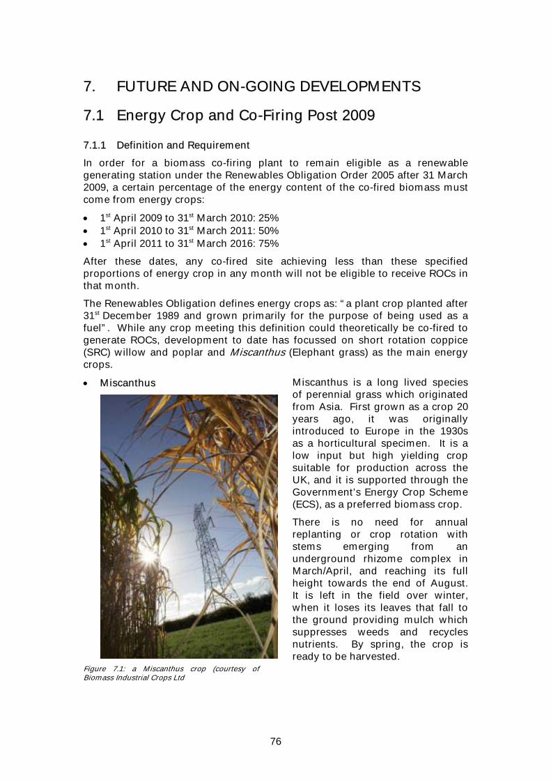
76
7. FUTURE AND ON-GOING DEVELOPMENTS
7.1 Energy Crop and Co-Firing Post 2009 7.1.1 Definition and Requirement
In order for a biomass co-firing plant to remain eligible as a renewable generating station under the Renewables Obligation Order 2005 after 31 March 2009, a certain percentage of the energy content of the co-fired biomass must come from energy crops:
• 1st April 2009 to 31st March 2010: 25% • 1st April 2010 to 31st March 2011: 50% • 1st April 2011 to 31st March 2016: 75%
After these dates, any co-fired site achieving less than these specified proportions of energy crop in any month will not be eligible to receive ROCs in that month.
The Renewables Obligation defines energy crops as: “a plant crop planted after 31st December 1989 and grown primarily for the purpose of being used as a fuel”. While any crop meeting this definition could theoretically be co-fired to generate ROCs, development to date has focussed on short rotation coppice (SRC) willow and poplar and Miscanthus (Elephant grass) as the main energy crops.
• Miscanthus
Figure 7.1: a Miscanthus crop (courtesy of Biomass Industrial Crops Ltd
Miscanthus is a long lived species of perennial grass which originated from Asia. First grown as a crop 20 years ago, it was originally introduced to Europe in the 1930s as a horticultural specimen. It is a low input but high yielding crop suitable for production across the UK, and it is supported through the Government’s Energy Crop Scheme (ECS), as a preferred biomass crop.
There is no need for annual replanting or crop rotation with stems emerging from an underground rhizome complex in March/April, and reaching its full height towards the end of August. It is left in the field over winter, when it loses its leaves that fall to the ground providing mulch which suppresses weeds and recycles nutrients. By spring, the crop is ready to be harvested.

77
• Short Rotation Coppice (SRC) SRC consists of densely planted, high-yielding varieties of either willow or poplar, commonly harvested on a 3 – 4 year cycle, although with the new higher yielding varieties that are becoming available, this is expected to drop to once every 2 years.
SRC has certain advantages for co-firing: many fossil-fuelled stations have proven the technical capability of co-firing wood, it is relatively energy-dense reducing transportation costs and impacts, and it has been already been grown at a reasonable scale in the UK.
Although historically the majority of SRC that was available in the UK was planted to supply the ARBRE 10MW gasification plant near Selby, Yorkshire, other substantial sources of this feedstock are now becoming available. However, significant additional amounts of SRC will need to be planted in order to meet the requirements of co-firing in April 2009. Due to the 3-4 year gap between planting and productive harvesting of SRC, the crop needs to be planted spring/early summer 2005, or 2006 at latest, to be available for co-firing from April 2009.
Additional factors that are likely to limit the availability of SRC and miscanthus as energy crop include:
• The physical location of power plant • The commercial risks for both grower and generator
7.1.2 Physical Location The location of some stations may preclude the growing of SRC or Miscanthus in their area. The guidelines for receipt of a Defra grant for energy crop is that it should be planted within a 25 mile radius of the market. However, generators and developers can make a case for extending the catchment area beyond 25 miles if there are no major environmental issues in so doing. Nonetheless, given that in most cases the grant is required to make crops like SRC and miscanthus commercially viable for farmers, it is unlikely that large areas of energy crops will be sourced from outside the immediate vicinity of a power station.
Figure 7.2: Kingsnorth Power Station (courtesy of E.ON UK plc)

78
Stations located on the coast, on an estuary, surrounded by urban areas or a land type that is unsuitable for growing these energy crops (eg due to soil type, rainfall, altitude etc) may be physically unable to meet their energy crop requirements from these sources, even if all the suitable land within a 25 mile radius was used to grow SRC and miscanthus. Stations in Wales may find it particularly difficult to encourage farmers to plant these crops as the Defra energy crop support package is only available for growers in England.
The availability of energy crops will also be influenced by the crops currently grown in an area: where stations are located in high value crop (eg sugar beet, potatoes) areas, there will be insufficient commercial incentive for the land to be used to grow SRC or miscanthus. Where there are a number of stations in close proximity (eg Midlands and Yorkshire) there may not be enough land to supply the energy crop requirements of all generators from these sources. 7.1.3 Commercial Risks
The long-term, perennial nature of the SRC and miscanthus and the need (particularly with SRC) to establish contracts at least 4-5 years in advance of receiving the supply, creates a number of barriers to establishment of commercial supplies of these fuels.
Of these, perhaps the most significant is the limited period of demand from co-fired plant set by the 2016 deadline for co-firing, resulting in a sudden reduction in the energy crop market post 2016.
These factors lead to a number of issues that are preventing the large scale uptake of SRC and miscanthus as energy crops:
• Agreeing a contract price 4-5 years out, with uncertainty on power price, ROC price, coal price and income from alternative crops/land uses (generator and grower).
• Credit risk, overhead costs and reliability of supply risk associated with contracting with a large number of small suppliers (generator) This can be partially mitigated by a single contract with an intermediary or consolidator, but supply liability still needs to be distributed between the two parties and credit risk remains an issue.
• Illiquidity of market for SRC and miscanthus (generator and grower).
• Political uncertainty associated with CAP reform, the review of the Renewables Obligation and the long-term power and agricultural markets (generator and grower).
• Price convergence (generator and grower).
• Income gap between planting and first productive harvest (grower).
• Receivership risk of power companies (grower).
• Concerns associated with growing (primarily yield and harvesting) and co-firing (processing and combustion) energy crops (grower and generator).
• Acceptability to Stakeholders of large-scale planting of SRC and miscanthus.
It is hoped that these potential barriers can be overcome. Generators are now active in the market and working with farmers to offer contracts for supply, particularly of SRC, into co-firing schemes.

79
Howewer, it is unlikely that either SRC or miscanthus will be available in sufficient quantities for co-firers to meet the energy crop requirements of the Renewables Obligation in April 2009.
In the meantime, it may be possible to develop alternative energy crops sources based on other annual rotational crops which are well understood by farmers, are easily adopted, and consequently have lower technical and commercial risks associated with them. However, if such supplies are not developed, there is likely to be a significant reduction in the potential contribution of co-firing to renewable energy targets between 2009 and 2016.
7.2 Clarification of Longer-Term Plant Impacts Based on the information gathered on experience of biomass co-firing from around the world, a number of potential longer-term “balance of plant” impacts have been identified, which continue to be monitored on those plant that are commercially co-firing biomass in the UK. These issues include ash deposition, corrosion and erosion, ash quality, plant emissions, and impacts on electrostatic precipitator performance.
Figure 7.3 Boiler tube welding (courtesy of E.ON UK plc)
Of these it is the issue of plant corrosion that is currently generating the most concern. Although to date there have been no incidents of increasing boiler tube failure rates that have been directly attributable to biomass co-firing, the high alkali metal content of some biomass fuels has raised concerns that they may have an adverse impact in the longer term, particularly on the high temperature austenitic steels found in the superheater tube banks of many coal-fired boilers in the UK.
These concerns have arisen from the results of initial combustion rig testing of these fuels, funded by the DTI.
Historically, rig testing techniques have been developed for assessing the impact of new fuels on large utility plant. These included methods for assessing the propensity for such fuels to increase corrosion rates and hence
80
impact upon the commercial operation of the plant by reducing availability and/or increasing maintenance costs. The DTI funded work on biomass co-firing, which used these techniques, has indicated very significant increases in corrosion rates during relatively short 50 hour runs co-firing 10 to 20% blends (on a thermal basis) of the biomass fuels containing the highest proportions of alkali metals.
Work is continuing to investigate these issues further and establish the likely magnitude of these effects during biomass co-firing operations at more representative co-firing rates on full scale commercially operational plant.
The results of the DTI sponsored work, and other corrosion tests firing 100% biomass, have also raised concerns about the likely impacts of direct injection schemes on corrosion rates, since under these conditions it would be possible (depending upon the mixing and flow regimes within the boiler) for undiluted products of biomass combustion to impinge upon areas of tubing.
The relatively limited experience of large-scale commercial co-firing operations in the UK, and the on-going developments with respect to increasing co-firing capacity and the utilisation of different techniques for supplying the fuel to the boiler, mean that new issues are still likely to be encountered. While ever co-firing remains commercially attractive, appropriate initiatives will be developed to address these issues as they arise.
7.3 Co-Firing Post 2016 Under current legislation, co-firing will not be eligible for ROC’s after 31st March 2016. With the current price differential between fossil fuels and bio-fuels, it is only the additional ROC and LEC income that makes bio-fuels economic. Save for a change in the Renewables Obligation, substitution of fossil fuels with co-fired biomass will only continue post 2016 if the marginal costs of co-firing converge with those of fossil fuel generation.
Implementation of the Large Combustion Plant Directive requires those assets opting out to be limited to a maximum of 20,000 operating hours from 2008, and in any event shall close by the end of 2015 at the latest. The asset base available to participate in co-firing activities post 2016 is clearly likely to be restricted by the retirement of existing coal fired power stations, irrespective of changes in the eligibility of co-firing under the Renewables Obligation.
The requirement for a substantial fraction of co-fired biomass to be energy crop from 2009 is another potentially limiting factor, as the establishment of energy crop plantation is very slow at the moment. Without a step change in establishment rate, or a widening of the energy crops market to include annual crops, it is difficult to see that sufficient supply of energy crops will be available to avoid restricting the biomass co-firing from 2011 when 75% of ROC eligible co-fired biomass has to be energy crop. This, combined with plant closures under LCPD, could easily lead to a significant decrease in co-firing activities well before 2016.

81
Figure 7.4: Ferrybridge Power Station (courtesy of E.ON UK plc)
82
8 CONCLUSIONS • Co-firing is practical, environmentally beneficial and is making a real
contribution to the Government’s renewable targets. • Most UK coal-fired generators have co-fired significant quantities of
biomass and continue to do so. • When co-firing in large utility boilers, the efficiencies achieved in the
conversion of biomass to electricity are relatively high compared to other commercially available technologies.
• It is the enactment of the Renewables Obligation, the associated trading of
Renewables Obligation Certificates, and the contribution from Levy Exemption Certificates that have made biomass co-firing at existing stations economically viable, despite operational difficulties and a fuel price of more than twice that of coal.
• Co-firing has also been successful in stimulating markets for both energy
crop and non-energy crop biomass fuels in the UK. • The legislation governing the use of biomass as a renewable energy source
is highly complex and is derived from a number of sources. The interrelationship between these, and the changing nature of some of this legislation, has created a level of uncertainty within the market.
• The tightening of the legislative cap on co-firing in 2006 and 2011 is likely to
restrict future growth in co-fired output and the contribution it makes to achieving the Government’s renewable generation targets.
• Market uncertainty has hampered investment in more expensive schemes,
and resulted in co-firing operations generally being developed on the basis of short lead times and low capital investment.
• The operational implications of co-firing are significant and generally not
fully appreciated. Particularly when co-milling, biomass fuels must be matched closely with individual plant designs for optimum performance, and most stations that have experience of commercial co-firing have had to overcome a number of technical issues. Among those most important have been the health and safety implications of co-firing a more reactive fuel than the plant was originally designed to handle.
• Where technical issues lead to limitations on plant flexibility or availability,
co-firing can also have an adverse impact on the trading of the electricity produced by the station.
• Because of these issues the economics of co-firing are complex, and there is
plenty of potential for the costs of co-firing operations to outweigh the benefits.

83
• Despite these issues, operators are continuing to assess future biomass fuel and technology options, including options for using energy crops and schemes for achieving direct injection of biomass.
• Generation companies in the UK now have significant experience of co-
firing biomass. They have developed solutions to many of the problems that have been encountered, and these have enhanced their understanding of where the optimum technical solutions for future development lie.
Figure 8.1: Kingsnorth Power Station (courtesy of E.ON UK plc)
84
9 REFERENCES
9.1 Useful Web sites
• “Our energy future – creating a low carbon economy” – Energy White Paper, DTI www.dti.gov.uk/energy/whitepaper/index.shtml
• Creating a Low Carbon Economy - First Annual Report on Implementation of the Energy White Paper www.dti.gov.uk/energy/sepn/firstannualreport.shtml
• Environment Agency : Integrated Pollution Prevention and Control (IPPC) www.environment-agency.gov.uk/business/444217/444663/298441/?lang=_e
• Climate Change Agreements and the Climate Change Levy http://www.defra.gov.uk/environment/ccl/
• The Renewables Obligation www.dti.gov.uk/renewables/renew_2.2.htm
• “Air Quality: Large Combustion Plant Directive” – Defra www.defra.gov.uk/environment/airquality/lcpd/
• Statutory Instrument 2002 No. 2980: The Waste Incineration (England and
Wales) Regulations 2002 www.hmso.gov.uk/si/si2002/20022980.htm
• Support for Energy Crops http://www.defra.gov.uk/farm/acu/energy/energy.htm
9.2 Telephone numbers • DTI: 02072 155000 • Defra: 08459 335577
9.3 Contacts
• Mike Colechin, Combustion Engineer, E.ON UK – Power Technology Tel: 0115 936 2000 Email: [email protected]
• Alf Malmgren, Combustion Engineer, RWE Power International Tel: 01793 893164 Email: [email protected]
• Paul Mernagh, Head of Green Fuels Commercial, npower renewables Tel: 07989 494345 Email: [email protected]