best final ddk hsr both
TRANSCRIPT
5/14/2018 Best Final Ddk Hsr Both - slidepdf.com
http://slidepdf.com/reader/full/best-final-ddk-hsr-both 1/54
CONTENTS
• Acknowledgement
• About Doordarshan Kendra Hisar
• Studio
• Equipment Room
• Video Basics
• Production Control Room
• Editing Room
• Earth Station
• High Power Transmitter
• PDA-Parabolic Dish Antenna
Acknowledgement
5/14/2018 Best Final Ddk Hsr Both - slidepdf.com
http://slidepdf.com/reader/full/best-final-ddk-hsr-both 2/54
Words fail to express ones feeling towards other still we express our sincere
gratitude to Sh. D.P. Singh, Assistant Engineer DOORDARSHAN
KENDRA, HISAR for their valuable guidance without which it would have
been difficult for us to achieve our aim.
we also express our gratitude to Sh. Sandeep Kaushik , Sh. S.N. Gera,
Sh. B.S.Bisth, Prithvi Singh Dahiya ,Sh. N. K. Gijwani , Sh. Chander
SEN who helped a lot in studying the various instruments.
It was really a good experience working in the institute and learning from such
good and knowledgeable people. We hope it would be really helped to us in the
near future.
ISHANTSANCHIT SINDHWANI
ANIL SHARMA
MAHARISHI MARKENDESHWAR ENGINEERING COLLEGE, MULLANA
DOORDARSHAN KENDRA,
HISAR
5/14/2018 Best Final Ddk Hsr Both - slidepdf.com
http://slidepdf.com/reader/full/best-final-ddk-hsr-both 3/54
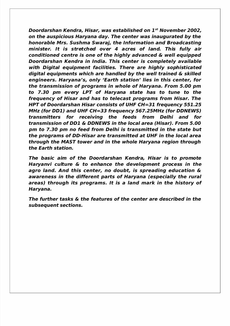
Doordarshan Kendra, Hisar, was established on 1st November 2002,
on the auspicious Haryana day. The center was inaugurated by the
honorable Mrs. Sushma Swaraj, the Information and Broadcasting
minister. It is stretched over 4 acres of land. This fully air
conditioned centre is one of the highly advanced & well equipped Doordarshan Kendra in India. This center is completely available
with Digital equipment facilities. There are highly sophisticated
digital equipments which are handled by the well trained & skilled
engineers. Haryana’s, only ‘Earth station’ lies in this center, for
the transmission of programs in whole of Haryana. From 5.00 pm
to 7.30 pm every LPT of Haryana state has to tune to the
frequency of Hisar and has to telecast programs from Hisar. The
HPT of Doordarshan Hisar consists of UHF CH=31 frequency 551.25
MHz (for DD1) and UHF CH=33 frequency 567.25MHz (for DDNEWS)
transmitters for receiving the feeds from Delhi and for
transmission of DD1 & DDNEWS in the local area (Hisar). From 5.00
pm to 7.30 pm no feed from Delhi is transmitted in the state but
the programs of DD-Hisar are transmitted at UHF in the local area
through the MAST tower and in the whole Haryana region through
the Earth station.
The basic aim of the Doordarshan Kendra, Hisar is to promote
Haryanvi culture & to enhance the development process in the
agro land. And this center, no doubt, is spreading education &awareness in the different parts of Haryana (especially the rural
areas) through its programs. It is a land mark in the history of
Haryana.
The further tasks & the features of the center are described in the
subsequent sections.
5/14/2018 Best Final Ddk Hsr Both - slidepdf.com
http://slidepdf.com/reader/full/best-final-ddk-hsr-both 4/54
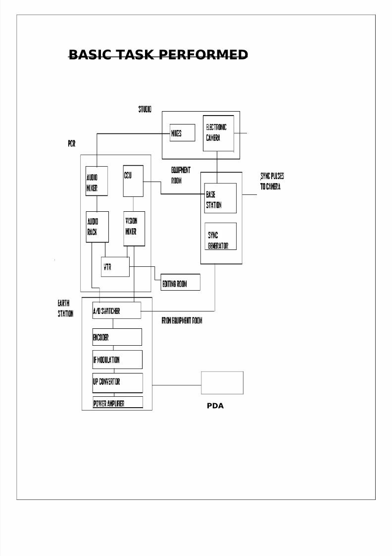
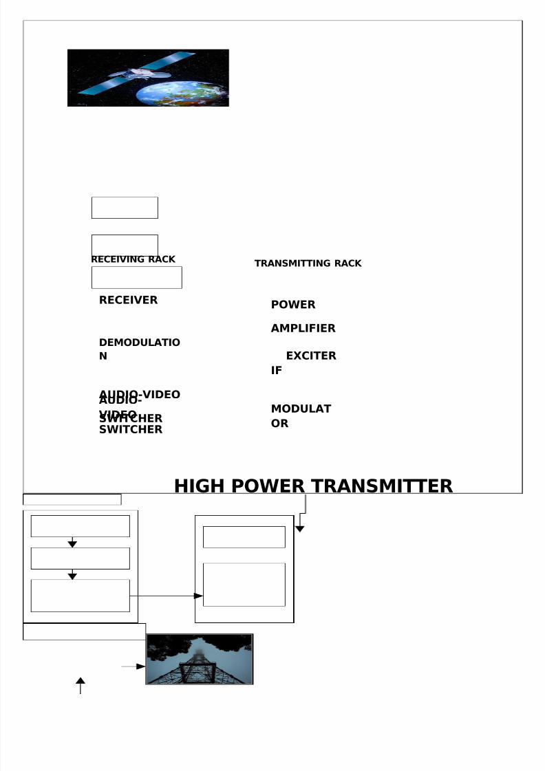
BASIC TASK PERFORMED
PDA
5/14/2018 Best Final Ddk Hsr Both - slidepdf.com
http://slidepdf.com/reader/full/best-final-ddk-hsr-both 5/54
HIGH POWER TRANSMITTER
AUDIO-VIDEO
SWITCHER
RECEIVER
DEMODULATIO
N
AUDIO-VIDEO
SWITCHER
RECEIVING RACK
POWER
AMPLIFIER
EXCITER
IF
MODULAT
OR
TRANSMITTING RACK
5/14/2018 Best Final Ddk Hsr Both - slidepdf.com
http://slidepdf.com/reader/full/best-final-ddk-hsr-both 6/54
STUDIO
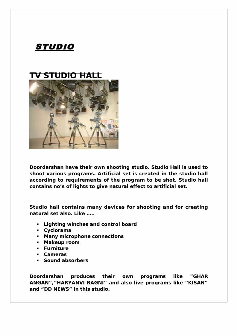
TV STUDIO HALL
Doordarshan have their own shooting studio. Studio Hall is used to
shoot various programs. Artificial set is created in the studio hallaccording to requirements of the program to be shot. Studio hall
contains no’s of lights to give natural effect to artificial set.
Studio hall contains many devices for shooting and for creating
natural set also. Like …..
Lighting winches and control board
Cyclorama
Many microphone connections Makeup room
Furniture
Cameras
Sound absorbers
Doordarshan produces their own programs like ”GHAR
ANGAN”,”HARYANVI RAGNI” and also live programs like ”KISAN”
and “DD NEWS” in this studio.
5/14/2018 Best Final Ddk Hsr Both - slidepdf.com
http://slidepdf.com/reader/full/best-final-ddk-hsr-both 7/54
Lights are hanged over the lighting winches and arranged in row.
Types and purpose for lighting will be explained under the title
“Studio Lighting”.
Cyclorama is nothing but a special type of white curtain hanged
with the wall in three dimensions. Cyclorama works as the light
and color absorbers to maintain original color tone on video
output. Because of its white color it is also used to create
background of various colors by using color paper on lightings
Many microphone connections hanged in between the winches are
used to attach the microphones during dialog delivery in play.
White colored walls act as a sound absorber material to reduce
the echoes.
Whole studio is centrally air conditioned and all the doors kept
airtight for preventing outer voice coming into studio.
Studio is also known as main action area. This place requires very
large place compared to other sections. Action in this area includes
staging, lighting, performance and arrangement to pickup picture
and sound.
Requirements of TV Studio:-
Very efficient air conditioning
Uniform and smooth floor for smooth movement of cameras
Efficient sound absorbers
Effective communication with other sections
3 to 4 studio cameras with teleprompter
Cyclorama and curtain
Audio and video monitors
Warning light and safety devices like fire alarm, firefightingequipment
Digital clock display
5/14/2018 Best Final Ddk Hsr Both - slidepdf.com
http://slidepdf.com/reader/full/best-final-ddk-hsr-both 8/54
STUDIO LIGHTING
The master key is used for creating 3-D and natural effect in studio.
Doordarshan uses 125 direct lights and 48 dimmers hanged on
winches in main recording studio.
Why lighting is done?
When we shoot outdoor program, the source of light is sun. The
natural effect we see in outdoor is greatly depends on the proper
lighting.
There are two main reasons to use light techniques in studio. First
is when we prepare artificial set to look like natural, we have to
give the proper lighting effect as if it was outdoor. Lighting also
depends on the mood of the scene. Secondly, the output picture of
the camera is 2D, while natural scenes we see are 3D, therefore on
T.V. screen to differentiate the main object from the background3D effect lighting is must.
Types of lights:-In Doordarshan halogen and cool day lights are
used.
Lighting techniques
To understand lighting techniques we should know all the
parameter of lights, those are…..
Quantity Quality
Color temperature
Contrast ratioQuantity means the amount of light or amount of radiated energy
by the source of light and quality means the type of light source
used.
Contrast ratio is the difference between highly lighted and darkestpart of the scene.
5/14/2018 Best Final Ddk Hsr Both - slidepdf.com
http://slidepdf.com/reader/full/best-final-ddk-hsr-both 9/54
Different lights and colors have their own temperature known as
color temperature. When a black body is heated, it may be noted
that color of body changes from black to red and then toward
white as temperature increases. Different sources have their own
Color temperature; some no’s of color temperature for different
light sources are listed below:
• Sun light 5600 Kelvin
• Studio lamp 3200 Kelvin
• Domestic lamp 2780 Kelvin
• Fire 1930 Kelvin
• Cloudy day 6500 Kelvin
• Clear blue sky 12000 Kelvin
Nature has provided us two types of light hard and soft.
Hard light is a point source light so the shadow of the object looks
sharper. In nature sun is the hard light source and other reflecting
clouds, hills and buildings are soft sources. The shadow of the
object under soft light source looks feathered and soft.
In studio mainly “THREE POINT LIGHTING” technique is used. Thesethree points are…
1. Key light2. Fill light3. Back light
KEY LIGHT:- is the main light used to highlight any object or to give
attention toward the person. This is full intensity light used to
highlight the depth of object or human face. Key light is usually a
hard source at an angle of 15-30 degree to camera axis at an
elevation of about 40 degree.
FILL LIGHT:-is the 80% intensity of key light and at the opposite side
of the camera axis. Fill light is used to suppress the shadow made
by key light. It is soft light and used to fill the light in whole room.
BACK LIGHT: - is used to separate artist from the background and so
to produce 3D visualization. It is hard source located at 180 degree
of camera axis.The three point lighting ratio 3:2:1(back: key: fill) in
monochrome and 3:2:2 in color provide good portrait lighting.
5/14/2018 Best Final Ddk Hsr Both - slidepdf.com
http://slidepdf.com/reader/full/best-final-ddk-hsr-both 10/54
The last is the background light used to highlight the background
of the scene or to create color background on white cyclorama.
BALANCE OF LIGHT:-
• Key light 100%• Fill light 85%• Back light 110%• Background light 50-60%
The motors attached with winches by metal belts control the height of
the lights. Movement of winches is controlled from the control panel
which also contains the connection for talkback system. Intensity
and power on/off of lights are controlled from the LCU(light control
unit).
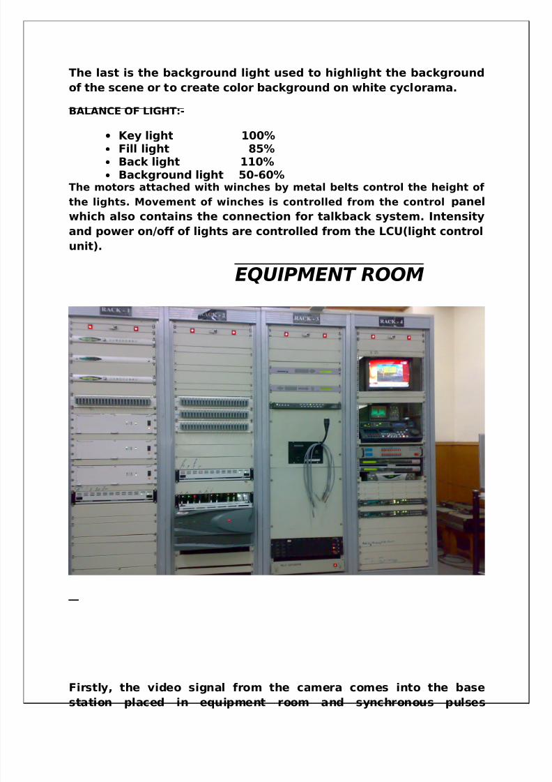
EQUIPMENT ROOM
Firstly, the video signal from the camera comes into the base
station placed in equipment room and synchronous pulses
5/14/2018 Best Final Ddk Hsr Both - slidepdf.com
http://slidepdf.com/reader/full/best-final-ddk-hsr-both 11/54
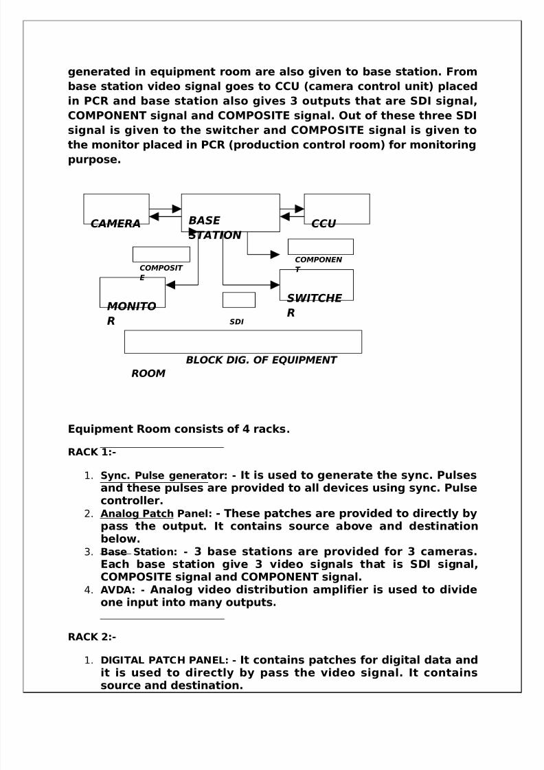
generated in equipment room are also given to base station. From
base station video signal goes to CCU (camera control unit) placed
in PCR and base station also gives 3 outputs that are SDI signal,
COMPONENT signal and COMPOSITE signal. Out of these three SDI
signal is given to the switcher and COMPOSITE signal is given tothe monitor placed in PCR (production control room) for monitoring
purpose.
Equipment Room consists of 4 racks.
RACK 1:-
1. Sync. Pulse generator : - It is used to generate the sync. Pulsesand these pulses are provided to all devices using sync. Pulsecontroller.
2. Analog Patch Panel: - These patches are provided to directly bypass the output. It contains source above and destination
below.3. Base Station : - 3 base stations are provided for 3 cameras.
Each base station give 3 video signals that is SDI signal,COMPOSITE signal and COMPONENT signal.
4. AVDA : - Analog video distribution amplifier is used to divideone input into many outputs.
RACK 2:-
1. DIGITAL PATCH PANEL : - It contains patches for digital data and
it is used to directly by pass the video signal. It containssource and destination.
CAMERA BASE
STATIONCCU
MONITO
R
SWITCHE
RSDI
COMPOSIT E
COMPONEN
T
BLOCK DIG. OF EQUIPMENT
ROOM
5/14/2018 Best Final Ddk Hsr Both - slidepdf.com
http://slidepdf.com/reader/full/best-final-ddk-hsr-both 12/54
2. A/D CONVERTER : - This converter is provided to convert analogsignal into digital signal because switcher can accepts onlySDI (digital) video signal.
3. SWITCHER :- Switcher used in Doordarshan is PINNACLE PDS9000 and it costs 3crore and 20 lakh. All the outputs of VTR’S,
CAMERAS etc are given as input to switcher and the output of switcher is the final output to display.
RACK 3:-
1. LOGO GENERATOR :- The logo generator is used to generatelogo’s on T.V screen like
2. INTERNAL TALKBACK SYSTEM :-It is provided for internalcommunication between producer and cameraman.
3. PATCH CODES :-These are the wires used to facilitate easybypass for defective equipment.
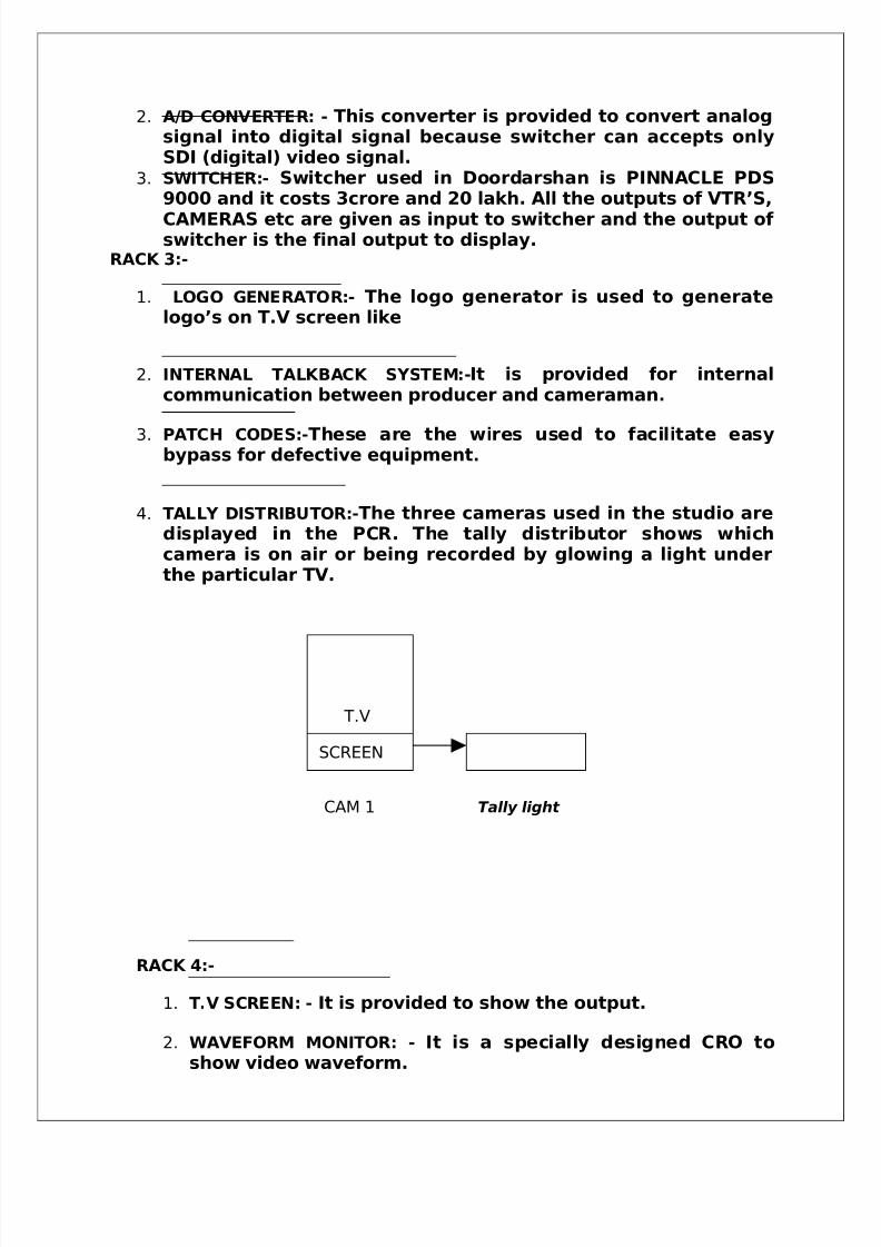
4. TALLY DISTRIBUTOR :-The three cameras used in the studio aredisplayed in the PCR. The tally distributor shows whichcamera is on air or being recorded by glowing a light underthe particular TV.
RACK 4:-
1. T.V SCREEN : - It is provided to show the output.
2. WAVEFORM MONITOR : - It is a specially designed CRO toshow video waveform.
T.V
SCREEN
CAM 1 Tally light
5/14/2018 Best Final Ddk Hsr Both - slidepdf.com
http://slidepdf.com/reader/full/best-final-ddk-hsr-both 13/54
3. IRD :-Integrated Receiver Decoders used to receive thesignal from the satellite and provide the QPSK demodulation to the received signal. It also separates thesignal into video and audio signal.
4. FRAME SYNCHRONIZER:-It is used to synchronize the outsidesignal coming from the satellite that is it converts thevideo signal into SDI (Serial Digital Interface) video signalbecause switcher can accept only SDI signal.
VIDEO BASICS
PRODUCING VIDEO
It begins with the lens system which focuses an image of the scene
onto a light sensitive surface within the camera head. In most
video cameras, the light sensor is a solid state CCD (chargecoupled device).
CCD
CCD is typically 12.5mm or 18mm across, and consists of hundreds
of thousands of tiny independent cells. Each cell develops an
electrical charge according to the strength of the light falling upon
it. The result is an overall pattern of electrical charges on the CCD,
that corresponds to the light and shade in the lens image.
To produce video signal scanning circuits continually read across
this charge pattern in a series of parallel path or lines(625).
Fluctuating voltage produced, corresponds to the strength of each
cell in turn. This is how a monochrome (black and white) camera
generates its picture.
In practical cameras which are colored (as in DDK Hisar) video
cameras use 3 CCD format. There are a number of variations too, in
5/14/2018 Best Final Ddk Hsr Both - slidepdf.com
http://slidepdf.com/reader/full/best-final-ddk-hsr-both 14/54
the types of CCD used and their resolution. Top quality cameras
can resolve 700 vertical black and white stripes across the picture
width, simpler cameras may only be able to reproduce half the
number. Color fidelity is less accurate or consistent in simpler
designs, and there is a greater possibility of disturbing picturedefects. In best video cameras these are negligible.
RECREATING THE PICTURE
To convert the video signal back into the picture, use of either
picture tube or an LCD screen is done. Most TV receivers, picture
monitors, camera viewfinders, use picture tubes of various sizes.
In picture tube abeam of electrons scans across the screen,
causing its phosphor coated surface to glow. When the video is
strongest the screen will glow brightly at that point. Where there
is little light reflected from the scene, the scene will appear much
darker.
HOW THE CAMERA SEES THE COLOR
The color video camera relies on the additive color mixing process.
Any light sensor (CCD) can respond to the intensity of light. Itcannot distinguish between color. By placing red, green and blue
color filters over three light sensors the scene can be analyzed into
separate color components. In the color video camera the lens
image of the scene passes through a special prism, which splits
into three identical versions. Three CCD sensors with their red,
green and blue color filters provide three video signals
corresponding to the light and shade of these colors in the scene.
5/14/2018 Best Final Ddk Hsr Both - slidepdf.com
http://slidepdf.com/reader/full/best-final-ddk-hsr-both 15/54
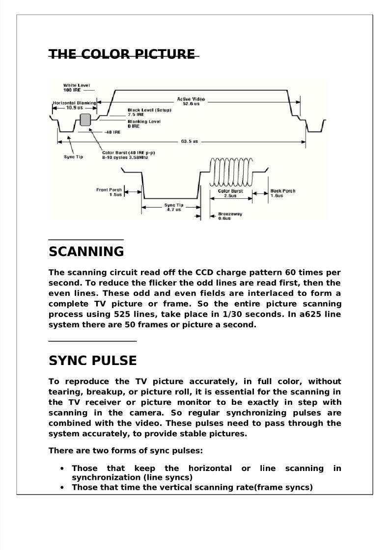
THE COLOR PICTURE
SCANNING
The scanning circuit read off the CCD charge pattern 60 times per
second. To reduce the flicker the odd lines are read first, then the
even lines. These odd and even fields are interlaced to form a
complete TV picture or frame. So the entire picture scanning
process using 525 lines, take place in 1/30 seconds. In a625 line
system there are 50 frames or picture a second.
SYNC PULSE
To reproduce the TV picture accurately, in full color, withouttearing, breakup, or picture roll, it is essential for the scanning in
the TV receiver or picture monitor to be exactly in step with
scanning in the camera. So regular synchronizing pulses are
combined with the video. These pulses need to pass through the
system accurately, to provide stable pictures.
There are two forms of sync pulses:
• Those that keep the horizontal or line scanning in
synchronization (line syncs)• Those that time the vertical scanning rate(frame syncs)
5/14/2018 Best Final Ddk Hsr Both - slidepdf.com
http://slidepdf.com/reader/full/best-final-ddk-hsr-both 16/54
The video information together with its sync pulses (including an
additional color burst signal which stabilizes color accuracy), is
called composite video.
The sync pulse is produced by SYNC PULSE GENERATOR. It has the
following features:
• The horizontal and vertical drive pulses that initiate thescanning process.
• The blackening pulses that suppress the scanning read-off asit moves on the next line or frame.
• The sync pulses at the end of each line and each field.
• The color burst which provides a reference signal to stabilize
color fidelity when encoding color information with theluminance information.
• Sometimes a signal black burst is generated. Thisincorporates blanking, syncs, and black video level. This black burst signal is used as a synchronizing source, and equipmentis genlocked onto it.
GENLOCK
All equipment in a video system needs to work from exactly the
same synchronization pulses. Otherwise when shots are inter
switched (cut or combined) there will be picture disturbances such
as frame roll, displacement etc. To avoid this, sync pulses from the
video sources are used to synchronize all units via a genlock unit,
so that they scan in unison. Genlock unit may generate either a
standard NTSC (PAL, SECAM) signal over a signal conductor
combined Y and C or separate Y and C.
COLOR VIDEO
Although it is possible to transmit color from camera to screen in
the form of three separate color components red, green and blue
video signals – there are technical disadvantages.
When the American NTSC color TV system was developed, itsdesigners had to ensure that color transmission could also be
5/14/2018 Best Final Ddk Hsr Both - slidepdf.com
http://slidepdf.com/reader/full/best-final-ddk-hsr-both 17/54
received on black and white receivers. This required some
ingenious engineering tricks which are also used in derived PAL
and SECAM color system.
Picture information was coded into:
Luminance(Y): This conveys the brightness and light and dark
screen.
Chrominance(C): This conveys the color in the screen.
The chrominance component is quite complex, for it has two
features: I signal (red minus luminance) and Q signal (blue minus
luminance) – in PAL system called U and V.
FORMULAE FOR LUMINANCE
Y= .3R + .59G + .11B
Where R, G, B represents red green and blue respectively.
If R=0, B=0, G=0 then the video is black and if R=1, B=1, G=1 thenthe video is black. There are three types of video which depend
upon Y, R, G and B:
Component video: Y, R-Y, B-Y
SDI video: Y,C(modulation of R-Y and B-Y)
COMPOSITE video: Y (modulation of Y and C)
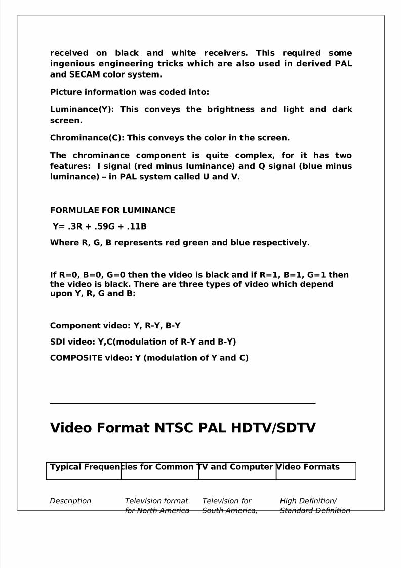
Video Format NTSC PAL HDTV/SDTV
Typical Frequencies for Common TV and Computer Video Formats
Description Television format
for North America
Television for
South America,
High Definition/
Standard Definition
5/14/2018 Best Final Ddk Hsr Both - slidepdf.com
http://slidepdf.com/reader/full/best-final-ddk-hsr-both 18/54
and Japan Europe and India Digital Television
Format
Vertical resolution
Format (visible
lines per frame)
Approx 480(525
lines per frame)
Approx 575 (625
total lines)
1080 or 720 or 480
18 different
formats
Horizontal
resolution Format
(visible pixels per
line)
Determined by
bandwidth; ranges
from 320 to 650
Determined by
bandwidth; ranges
from 320 to 720
1920 or 704 or 640
18 Different
formats
Horizontal
Rate (kHz)
15.734 15.625 33.75-45
Vertical Frame
Rate (Hz)
29.97 25 30-60
Highest
Frequency (MHz)
4.2 5.5 25
PRODUCTION CONTROL ROOM (PCR)
The generated signals in the studio are controlled and with some
effects and characters are added here.
The PCR usually of the various equipments like:-· Camera Control Unit (CCU)· Vision Mixer (VM)· Video Tape Recorder (VTR)· Audio Mixer (AM)
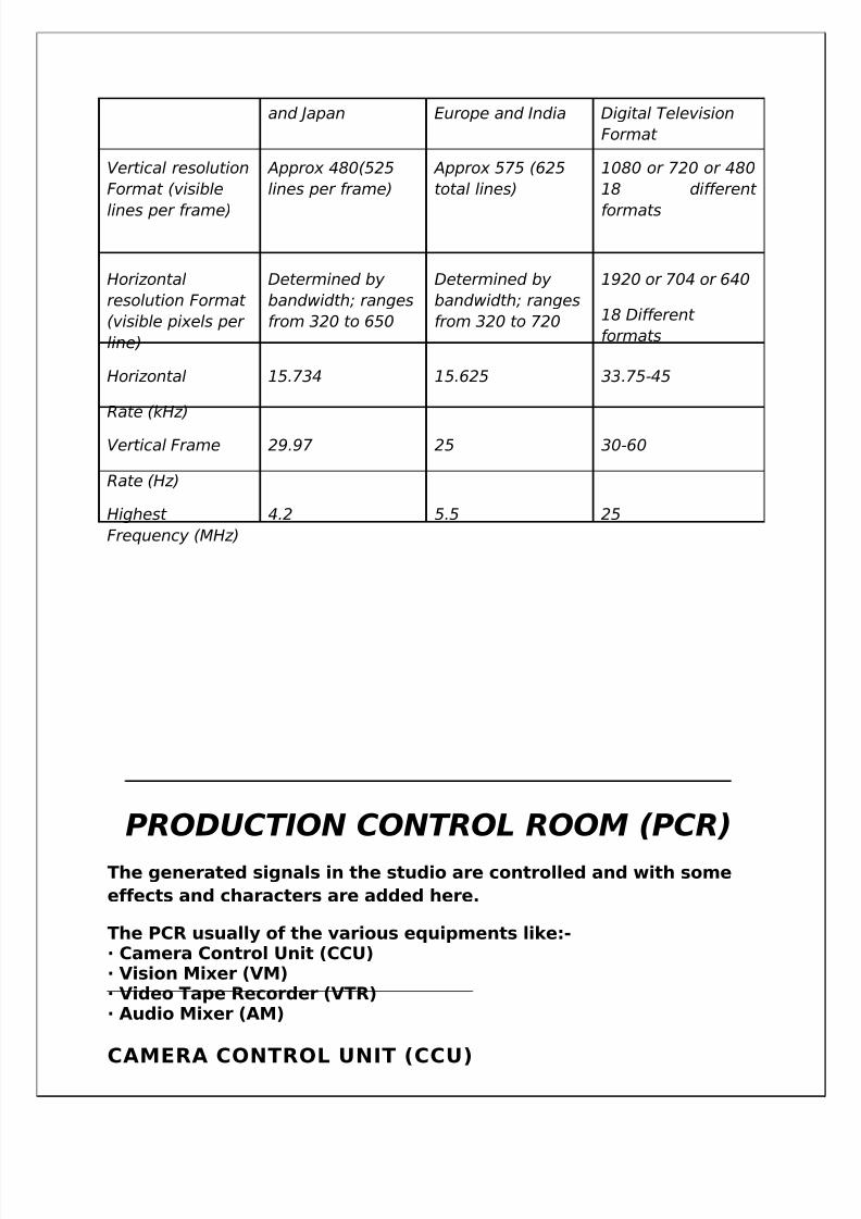
CAMERA CONTROL UNIT (CCU)
5/14/2018 Best Final Ddk Hsr Both - slidepdf.com
http://slidepdf.com/reader/full/best-final-ddk-hsr-both 19/54
The camera control unit (CCU) is installed in the production control room
(PCR), and allows various aspects of the video camera on the studio floor
to be controlled remotely. The most commonly made adjustments are for
white balance and aperture, although almost all technical adjustments
are made from controls on the CCU rather than on the camera. This frees
the camera operator to concentrate on composition and focus, and also
allows the technical director of the studio to ensure uniformity between
all the cameras.
Main functions of CCU are:
• Control the iris, shutter speed.
• Adjust color balances- white balance & black balance.
• Monitor and adjust a wide range of technical parameters.
• Send signals to the camera operator.
• To digitally amplify the signal.
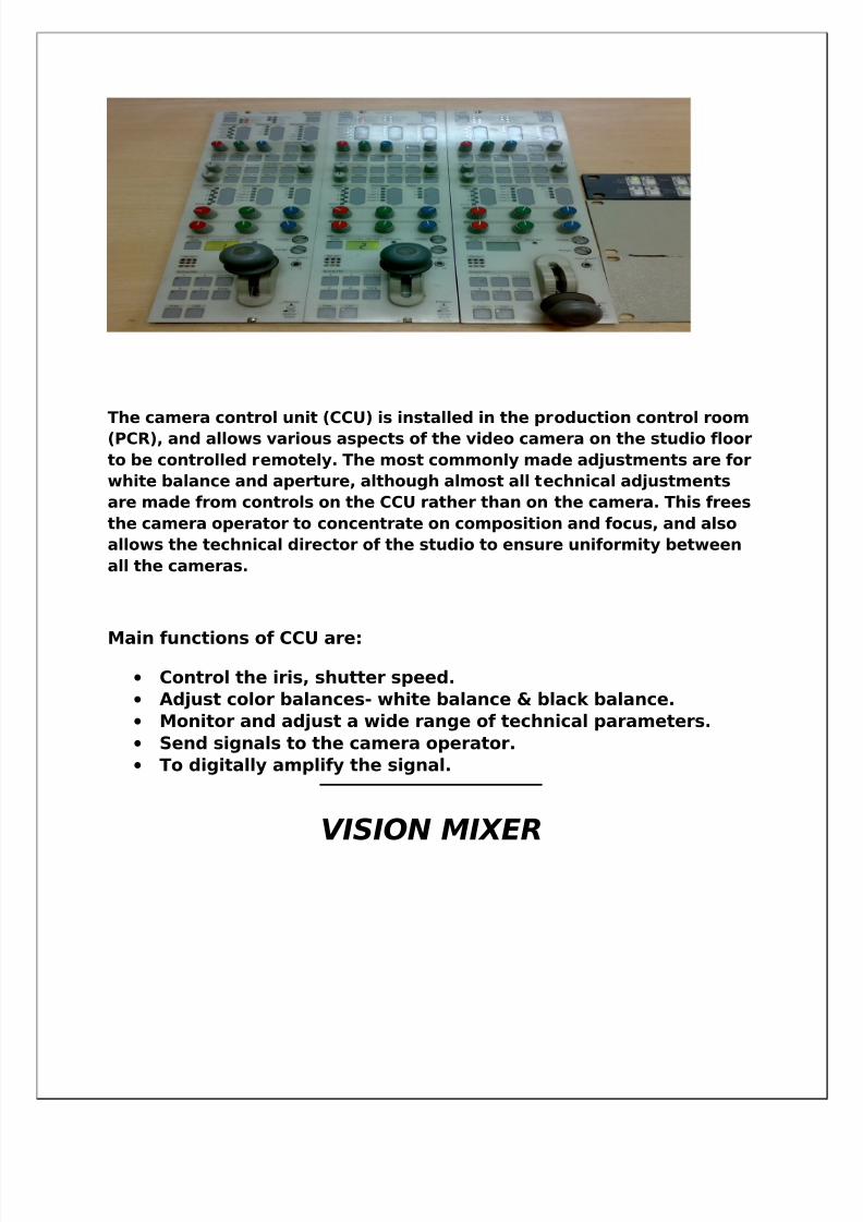
VISION MIXER
5/14/2018 Best Final Ddk Hsr Both - slidepdf.com
http://slidepdf.com/reader/full/best-final-ddk-hsr-both 20/54
The vision mixer is the destination point for all picture sources in
the studio. The output of all studio cameras, video tape recorder,
caption scanners, character generator etc are fed to the vision
mixing unit. The vision mixing involves basically 3 type’s transition
between the above sources. These transitions are mixing wiping
and keying. The output of mixer desk is fed to transmission
monitor, Transmission chain etc. in production control area. The
vision –mixing panels offers a lot visual effects that require time,
skill & costly auxiliary equipments. Some of the facilities of vision
mixer are explained here.
THE CUT
The cut is an instantaneous switch from one picture to another. It
avoids the frame roll & flash evident, on picture at the moment of
flash evident, on picture at the moment of cutting.
THE MIX
The transition here is less pronounced. As the faders are operated,
the established picture fades away, while the new picture
progressively while transition. The mixing is illustrated.
THE FADE UP/FADE OUT
5/14/2018 Best Final Ddk Hsr Both - slidepdf.com
http://slidepdf.com/reader/full/best-final-ddk-hsr-both 21/54
A selected channel can be fade up or fade out with the help of moving a fader up & down. The picture can be fade to black orfrom black.
THE SUPERIMPOSITION
Superimposition can be obtained by fading up two of more picturestogether. This may be used to add tilting to an existing picture orspecial picture or special montage effects.
PREVIEW
Vision mixers also have a preview blank & its output connected tomonitor. It enables us to check any selected non studio picturesbefore its translation.
THE WIPEThe wipe is common special effects. It can be described as onepicture chasing the original picture. The direction of entry of thepicture in original picture can be horizontal, vertical, diagonal,circular & so on.
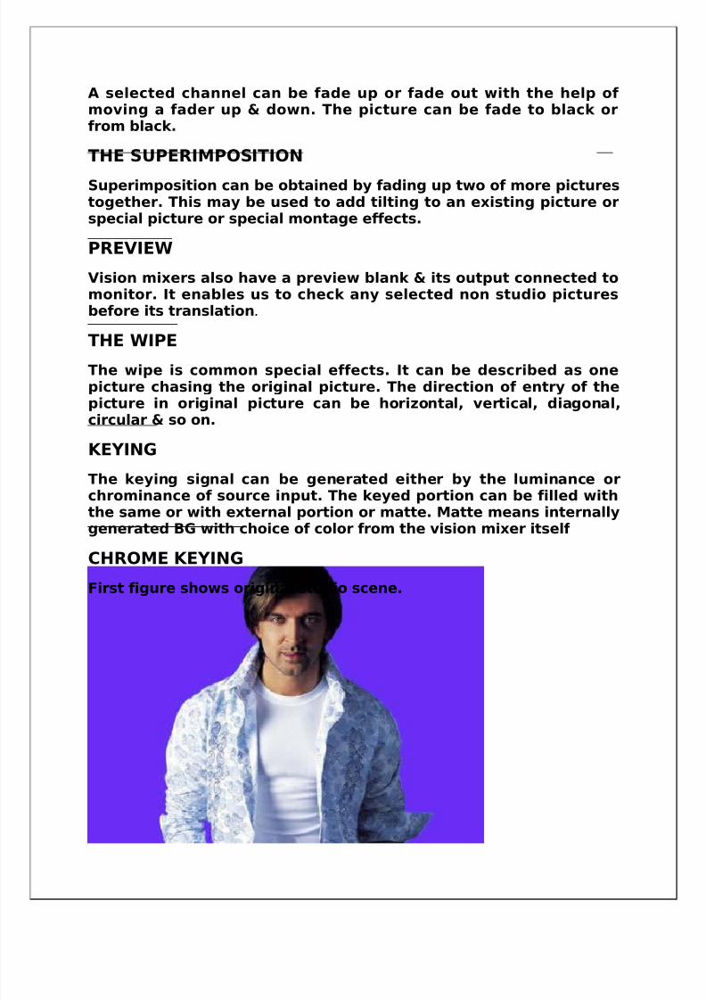
KEYING
The keying signal can be generated either by the luminance orchrominance of source input. The keyed portion can be filled withthe same or with external portion or matte. Matte means internally
generated BG with choice of color from the vision mixer itself
CHROME KEYING
First figure shows original studio scene.
5/14/2018 Best Final Ddk Hsr Both - slidepdf.com
http://slidepdf.com/reader/full/best-final-ddk-hsr-both 22/54
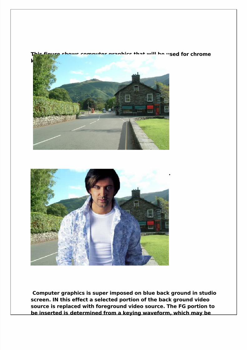
This figure shows computer graphics that will be used for chrome
keying.
This figure shows the result of the chrome keying.
Computer graphics is super imposed on blue back ground in studio
screen. IN this effect a selected portion of the back ground video
source is replaced with foreground video source. The FG portion tobe inserted is determined from a keying waveform, which may be
5/14/2018 Best Final Ddk Hsr Both - slidepdf.com
http://slidepdf.com/reader/full/best-final-ddk-hsr-both 23/54
derived from the foreground picture. Sometime this is also called
as color separation overlay (CSO)
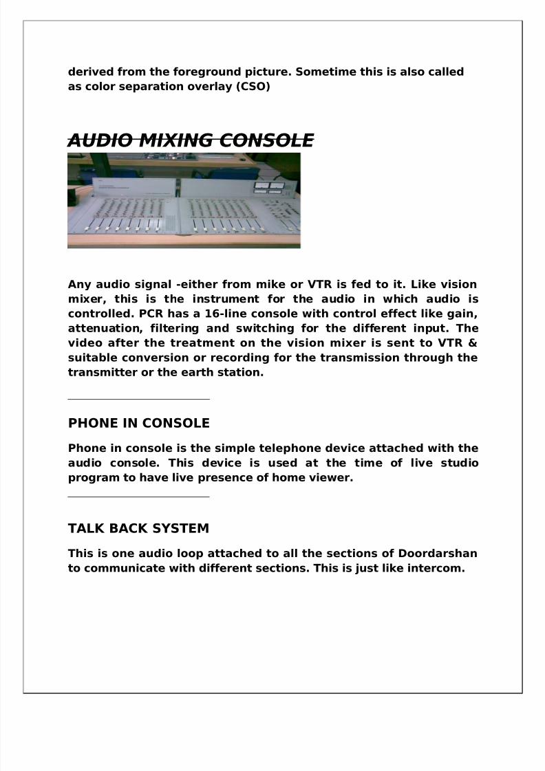
AUDIO MIXING CONSOLE
Any audio signal -either from mike or VTR is fed to it. Like vision
mixer, this is the instrument for the audio in which audio is
controlled. PCR has a 16-line console with control effect like gain,
attenuation, filtering and switching for the different input. The
video after the treatment on the vision mixer is sent to VTR &
suitable conversion or recording for the transmission through the
transmitter or the earth station.
PHONE IN CONSOLE
Phone in console is the simple telephone device attached with the
audio console. This device is used at the time of live studio
program to have live presence of home viewer.
TALK BACK SYSTEM
This is one audio loop attached to all the sections of Doordarshan
to communicate with different sections. This is just like intercom.
5/14/2018 Best Final Ddk Hsr Both - slidepdf.com
http://slidepdf.com/reader/full/best-final-ddk-hsr-both 24/54
VIDEO TAPE RECORDER
The VTR is the section where copies of all programs are stored. All
the programs shot in the camera are simultaneously recorded in
the VTR. Also the VTR plays back all the videos as and when
required. Videos of prerecorded Events are queued up in the VTR
and are played back without a Break.
A video tape recorder (VTR), is a tape recorder that can record
video materialIn VTR we use the following video tape formats
1. DVCPRO50(Panasonic)2. BETACAM (Sony)
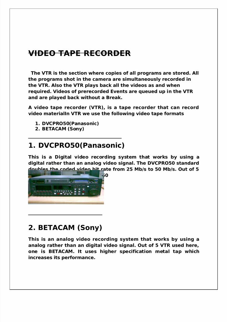
1. DVCPRO50(Panasonic)
This is a Digital video recording system that works by using a
digital rather than an analog video signal. The DVCPRO50 standard
doubles the coded video bit rate from 25 Mb/s to 50 Mb/s. Out of 5VTR used here,4 are DVCPRO50
2. BETACAM (Sony)
This is an analog video recording system that works by using a
analog rather than an digital video signal. Out of 5 VTR used here,
one is BETACAM. It uses higher specification metal tap which
increases its performance.
5/14/2018 Best Final Ddk Hsr Both - slidepdf.com
http://slidepdf.com/reader/full/best-final-ddk-hsr-both 25/54
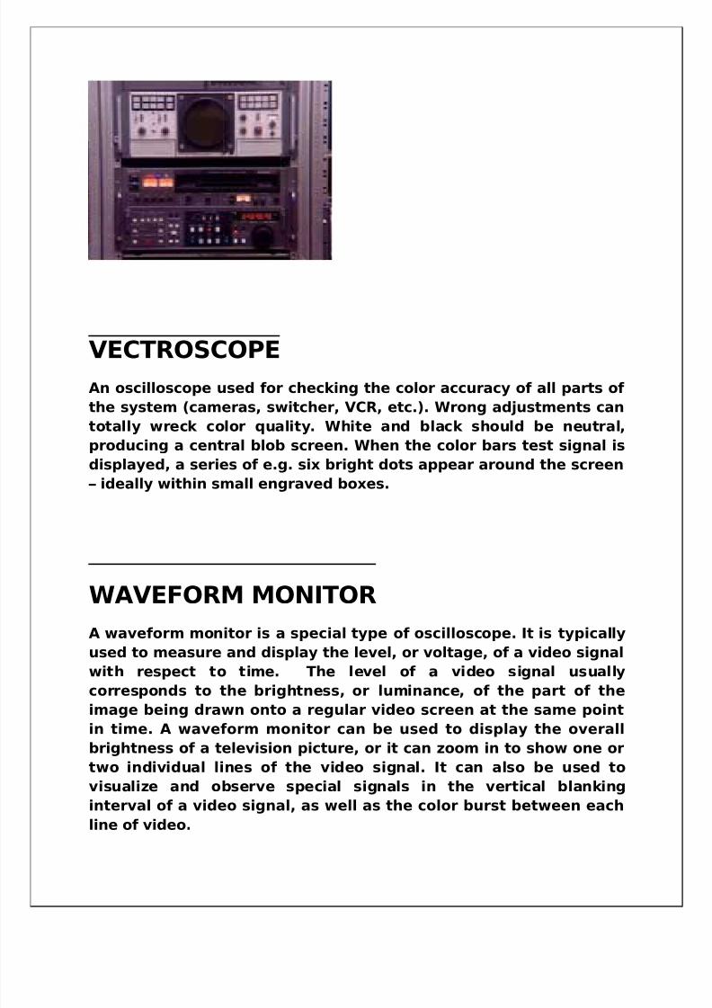
VECTROSCOPEAn oscilloscope used for checking the color accuracy of all parts of
the system (cameras, switcher, VCR, etc.). Wrong adjustments can
totally wreck color quality. White and black should be neutral,
producing a central blob screen. When the color bars test signal is
displayed, a series of e.g. six bright dots appear around the screen
– ideally within small engraved boxes.
WAVEFORM MONITOR
A waveform monitor is a special type of oscilloscope. It is typically
used to measure and display the level, or voltage, of a video signal
with respect to time. The level of a video signal usually
corresponds to the brightness, or luminance, of the part of the
image being drawn onto a regular video screen at the same point
in time. A waveform monitor can be used to display the overall
brightness of a television picture, or it can zoom in to show one or
two individual lines of the video signal. It can also be used to
visualize and observe special signals in the vertical blanking
interval of a video signal, as well as the color burst between each
line of video.
5/14/2018 Best Final Ddk Hsr Both - slidepdf.com
http://slidepdf.com/reader/full/best-final-ddk-hsr-both 26/54
CHARACTER GENERATOR
A character generator, often abbreviated as CG, is used to produce
static or animated text for keying into a video stream. Modern
character generators are computer-based, and can generategraphics as well as text.
EDITING
After recording a raw material using video tape recorders(VTR)
different types of correction is done using edit suit like as cutting
unwanted video & audio, making suitable timing for Broad-casting,
program name, actor name, director name etc. and also edit new
audio & different types of video pattern, new images , new
pictures.
There are unit time for any program, therefore we need editing
thus we can see continuous picture in our television.
There are two types of editing
1. Linear editing
2. Non linear editing
1. LINEAR EDITING
It is simple type of editing. In this type we can use only one or two
Players & recorders .Different video clips that we want to add or join with main program are played into cassettes players, and
5/14/2018 Best Final Ddk Hsr Both - slidepdf.com
http://slidepdf.com/reader/full/best-final-ddk-hsr-both 27/54
graphics that we want to add is selected to record on the tape. On
recorder the starting time and ending time is selected in between
which, mixing is done .Linear editing have disadvantage like it
takes more time. We can only add clip of length that we have
space on tape, means to add long clip, we can’t move video ontape, so overlapping occurs at that time. We can’t place more
images & pictures. Using linear editing we can interchange audio &
video only.
Other problems with linear tape based editing are:
• Editing in sequence-first shot first.
• Long hours spent on rewinding of tapes, Search of material.
• Potential risk of damage to original footage.
• Difficult to insert a new shot in edit.
• Difficult to experiment with variations
• Quality loss more in analog; even with digital
• Limited composing, effects, color, correction capability
2. NON LINEAR EDITING
• NLE is video editing in digital format with standard computer
based technology
• Computer technology is harnessed in random access,
computation and manipulation capability ,multiple copies
,Intelligent search, sophisticates projects and media
management tools, standard interfaces, and powerful display
• Flexibility in editing functions
5/14/2018 Best Final Ddk Hsr Both - slidepdf.com
http://slidepdf.com/reader/full/best-final-ddk-hsr-both 28/54
• Easy to do change - 28 -s, undo, copy, duplicate and
multiple version
• Easy operation for cut, dissolve, wipes and other transition
effects
• Multilayer of video becomes easy
• Powerful integration of video and graphics. Tools for filtering,
color correction, key framing & special 2D/3D effects.
• Equally powerful audio effects and mixing.
• Possible to trim, compress or expand the length of the clip
•
Support for multi format. Multi resolution clips
• Intelligent and powerful 3D video effect can be created and
customized.
• Efficient and intelligent storage
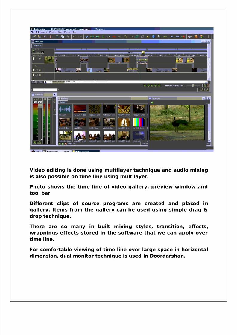
Non linear editing is done on time line using PC based software.
The figure shows the window of NLE software.
5/14/2018 Best Final Ddk Hsr Both - slidepdf.com
http://slidepdf.com/reader/full/best-final-ddk-hsr-both 29/54
Video editing is done using multilayer technique and audio mixing
is also possible on time line using multilayer.
Photo shows the time line of video gallery, preview window and
tool bar
Different clips of source programs are created and placed in
gallery. Items from the gallery can be used using simple drag &
drop technique.
There are so many in built mixing styles, transition, effects,
wrappings effects stored in the software that we can apply overtime line.
For comfortable viewing of time line over large space in horizontal
dimension, dual monitor technique is used in Doordarshan.
5/14/2018 Best Final Ddk Hsr Both - slidepdf.com
http://slidepdf.com/reader/full/best-final-ddk-hsr-both 30/54
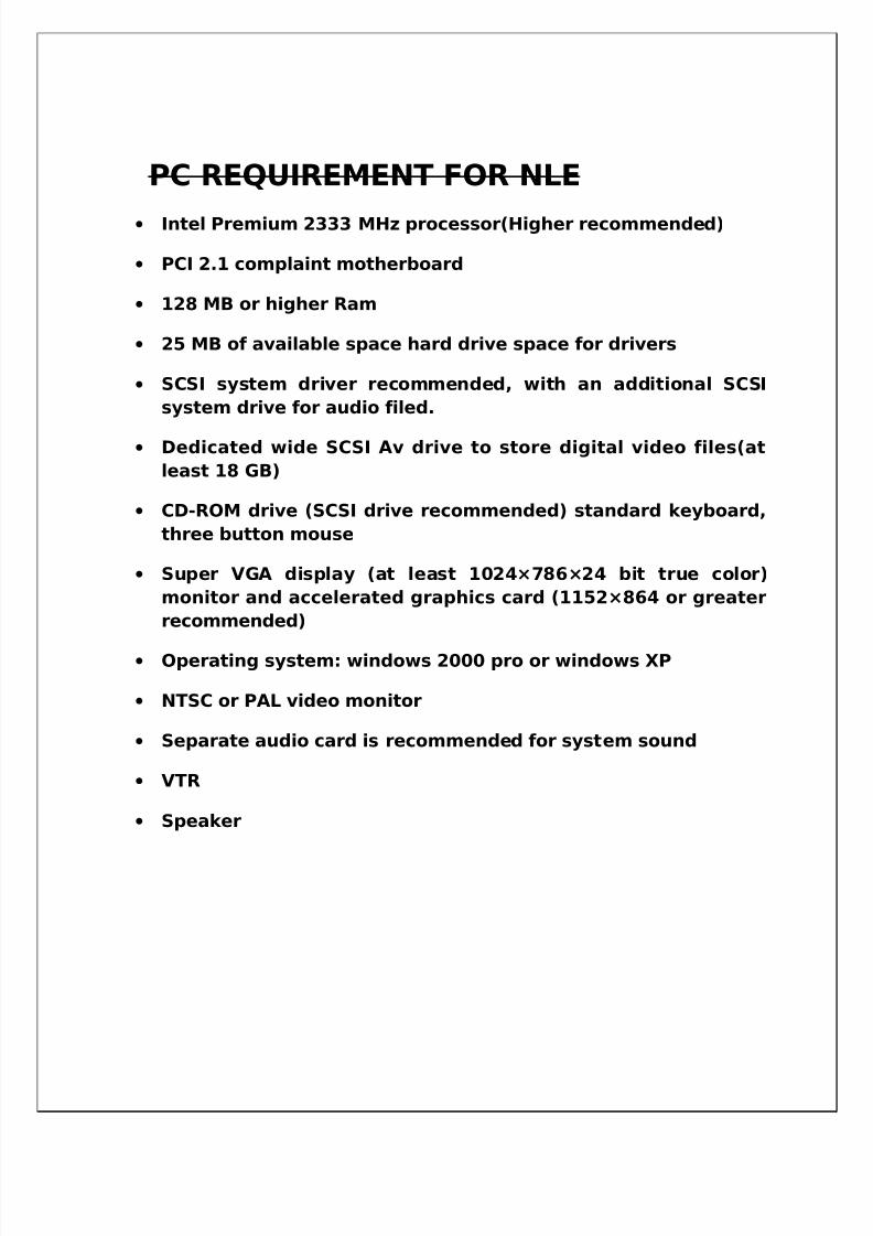
PC REQUIREMENT FOR NLE
• Intel Premium 2333 MHz processor(Higher recommended)
• PCI 2.1 complaint motherboard
• 128 MB or higher Ram
• 25 MB of available space hard drive space for drivers
• SCSI system driver recommended, with an additional SCSI
system drive for audio filed.
• Dedicated wide SCSI Av drive to store digital video files(at
least 18 GB)
• CD-ROM drive (SCSI drive recommended) standard keyboard,
three button mouse
• Super VGA display (at least 1024×786×24 bit true color)
monitor and accelerated graphics card (1152×864 or greater
recommended)
• Operating system: windows 2000 pro or windows XP
• NTSC or PAL video monitor
• Separate audio card is recommended for system sound
• VTR
• Speaker

5/14/2018 Best Final Ddk Hsr Both - slidepdf.com
http://slidepdf.com/reader/full/best-final-ddk-hsr-both 31/54
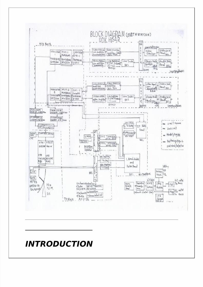
EARTH STATION
5/14/2018 Best Final Ddk Hsr Both - slidepdf.com
http://slidepdf.com/reader/full/best-final-ddk-hsr-both 32/54
INTRODUCTION
5/14/2018 Best Final Ddk Hsr Both - slidepdf.com
http://slidepdf.com/reader/full/best-final-ddk-hsr-both 33/54
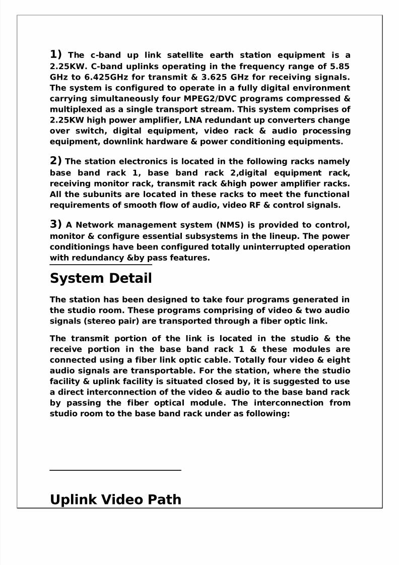
1) The c-band up link satellite earth station equipment is a
2.25KW. C-band uplinks operating in the frequency range of 5.85
GHz to 6.425GHz for transmit & 3.625 GHz for receiving signals.
The system is configured to operate in a fully digital environment
carrying simultaneously four MPEG2/DVC programs compressed &multiplexed as a single transport stream. This system comprises of
2.25KW high power amplifier, LNA redundant up converters change
over switch, digital equipment, video rack & audio processing
equipment, downlink hardware & power conditioning equipments.
2) The station electronics is located in the following racks namely
base band rack 1, base band rack 2,digital equipment rack,
receiving monitor rack, transmit rack &high power amplifier racks.
All the subunits are located in these racks to meet the functionalrequirements of smooth flow of audio, video RF & control signals.
3) A Network management system (NMS) is provided to control,
monitor & configure essential subsystems in the lineup. The power
conditionings have been configured totally uninterrupted operation
with redundancy &by pass features.
System Detail
The station has been designed to take four programs generated in
the studio room. These programs comprising of video & two audio
signals (stereo pair) are transported through a fiber optic link.
The transmit portion of the link is located in the studio & the
receive portion in the base band rack 1 & these modules are
connected using a fiber link optic cable. Totally four video & eight
audio signals are transportable. For the station, where the studio
facility & uplink facility is situated closed by, it is suggested to use
a direct interconnection of the video & audio to the base band rack by passing the fiber optical module. The interconnection from
studio room to the base band rack under as following:
Uplink Video Path
5/14/2018 Best Final Ddk Hsr Both - slidepdf.com
http://slidepdf.com/reader/full/best-final-ddk-hsr-both 34/54
Of the four program of the fiber optic receive module, program 1 &
2 Processed in the base band rack 1 & program 3 & 4 are
processed in the base band rack 2. To have full flexibility in the
program, the program 1 & 2signals also fed as an additional input
to the program switcher router in the base band rack 2.Similarlyprogram 3 & 4 are also fed to the program switcher in the based
band rack 1. Hence video and audio interaction is established for
this purpose
Each program comprises of a video signal and two audio signals
which can be configured as dual mono or stereo audio. The video
are processed as cable equalization & suppression, the video
signals are fed to the 8*2 router (program switcher) for the
program selection. The selected video signal is fed to the video
processing amplifier for the sync regeneration & adjustment of video signal amplitude. Necessary video distributors are presented
in the path for monitoring video in the path. In addition the signals
are passed through video jack panel (VJP) which is use full in
bypassing fault modules in the lineup.
Uplink Audio Processing
IN similar lines of the video processing, the audio signals are also
first equalize & fed along with video signals to the 8*2 router(program switch). The selected pair of the audio signals is further
processed for limiting the amplitude of the audio signal to a
specified limit using the limiter. The limiter helps to limit the
amplitude of the audio signal in the actual program. Necessary
distributors are also provided in the lineup for monitoring the
audio signals .Audio jack panels (AJP) are also provided for ease of
bypassing faulty modules.
The amplitude of the audio signal is measured using the Audio
Monitoring Panel (AMP) which has necessary VU meters for
indication of audio level.
Each base band rack gives out two programs outputs, which are
fed to the Digital; Equipment racks as base band signals.
This consists of four MPEG2 video encoder, two multiplexer & two
modulators configured to operate as a 4.0 system. The multiplier
generates a singles transport stream to carry four compressed
program signals. The multiplexer output is fed to the modulator so
the modulator so as to perform QPSK modulation at 70 MHz IF
corrector. The complete system including the network
5/14/2018 Best Final Ddk Hsr Both - slidepdf.com
http://slidepdf.com/reader/full/best-final-ddk-hsr-both 35/54
management is supplied by M/S Tandberg as a pre wired rack. Two
multiplexers & the modulator are provided are provided for
redundancy.
Up ConversionThe up conversion of digitally modulated IF signals is achieved first
by passing the IF carrier through a system equalizer in order to
correct the group delay and amplitude response of the complete
system including the satellite transponder. The equalizer output is
fed to the up converter so as to convert the IF carrier to the
transmitted “C” band carrier in the frequency range 5.85 to 6.65
GHz. Two set equalizers & up converters are provided along with a
redundancy controller to have redundancy for modulator, system
Equalizer, Up converter.
High power amplifier
The transmitted C band is amplified to 2.25KW power level in a
high amplifier rack to implement as a1:1 system.
The HPA rack comprises of two 2.25 KW HPA’s & a redundancy
controller for the 1:1 Redundancy operator.
Power Conditioning
The power for the operation comprises of Isolation Transformers
AVR, UPS power distribution panel. The ups are implemented as a
1:1 system. Due to the physical separation of the base band rack,
IF rack with respect to TX rack & HPA rack, two separate power
distribution panels are provided for the ease of distribution
MECHANICAL FEATURESThe earth Station electronics are housed in industry standard 19
inches conforming to IEC standards. The subsystems have been
located in various racks to take care of the convenient flow of
video, audio, RF, power & control signals. The racks are dust proof
& meet the specification of IP 54 ingress protection.
5/14/2018 Best Final Ddk Hsr Both - slidepdf.com
http://slidepdf.com/reader/full/best-final-ddk-hsr-both 36/54
Construction Details and features of 19
inch rack
The rack has a frame which is made by welding “9 Fold sheet metalsections. The corners are strengthened by corner brackets. On to
this frame work various parts of the rack line front glass door, back
door, side covers, top & bottom panel are assembled 19” mounting
angler having perforated mountings holes are provided on the
front & back rear side of the racks. These mountings holes are
provided on the front & back rear side of the racks. These
mountings angles can be mounted at different positions. The
position of the mountings angles depend on the supporting angles
made out of deep drawn steel are also mounted on these
mountings which are used to support & guide the subsystems.
Space required in the front & rear side of the equipment & also the
dept. of the equipment, a set of supporting angles made out of
deep drawn steel sheets are also mounted on these mountings
angles which are used to support & guide the subsystems.
TECHNICAL DATA SUMMARY
Number of video inputs : fourVideo frequency range : 25 to
5 MHz
Video input level : 1V
Format : CCIR PALB 625
Impedance : 75 Ohms unbalanced
Return Loss : 20db
Number of Audio inputs : Eight
Audio input level : 0 db
Audio frequency range : 25Hz to 15 KHz
Impedance : 600 ohms
Uplink frequency : 5.8 GHz to 6.4 GHz
Downlink frequency : 3.7 to 4.2 GHz
Output Power : 22.52 transmit “C” frequencyIntermodulation : -22 dbc (with 4 db output back off)
5/14/2018 Best Final Ddk Hsr Both - slidepdf.com
http://slidepdf.com/reader/full/best-final-ddk-hsr-both 37/54
AVR rating : 60KVA
Ups rating : 40 KVA
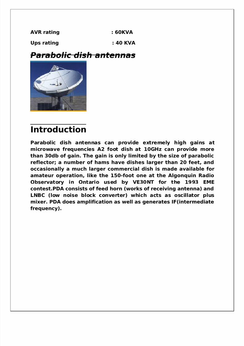
Parabolic dish antennas
Introduction
Parabolic dish antennas can provide extremely high gains at
microwave frequencies A2 foot dish at 10GHz can provide more
than 30db of gain. The gain is only limited by the size of parabolic
reflector; a number of hams have dishes larger than 20 feet, and
occasionally a much larger commercial dish is made available for
amateur operation, like the 150-foot one at the Algonquin Radio
Observatory in Ontario used by VE30NT for the 1993 EMEcontest.PDA consists of feed horn (works of receiving antenna) and
LNBC (low noise block converter) which acts as oscillator plus
mixer. PDA does amplification as well as generates IF(intermediate
frequency).
5/14/2018 Best Final Ddk Hsr Both - slidepdf.com
http://slidepdf.com/reader/full/best-final-ddk-hsr-both 38/54
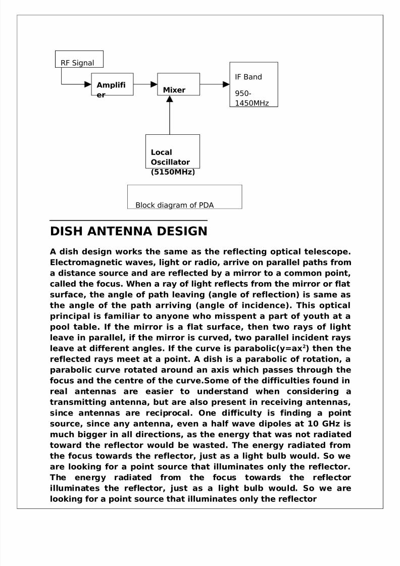
DISH ANTENNA DESIGN
A dish design works the same as the reflecting optical telescope.
Electromagnetic waves, light or radio, arrive on parallel paths from
a distance source and are reflected by a mirror to a common point,
called the focus. When a ray of light reflects from the mirror or flat
surface, the angle of path leaving (angle of reflection) is same asthe angle of the path arriving (angle of incidence). This optical
principal is familiar to anyone who misspent a part of youth at a
pool table. If the mirror is a flat surface, then two rays of light
leave in parallel, if the mirror is curved, two parallel incident rays
leave at different angles. If the curve is parabolic(y=ax2) then the
reflected rays meet at a point. A dish is a parabolic of rotation, a
parabolic curve rotated around an axis which passes through the
focus and the centre of the curve.Some of the difficulties found in
real antennas are easier to understand when considering atransmitting antenna, but are also present in receiving antennas,
since antennas are reciprocal. One difficulty is finding a point
source, since any antenna, even a half wave dipoles at 10 GHz is
much bigger in all directions, as the energy that was not radiated
toward the reflector would be wasted. The energy radiated from
the focus towards the reflector, just as a light bulb would. So we
are looking for a point source that illuminates only the reflector.
The energy radiated from the focus towards the reflector
illuminates the reflector, just as a light bulb would. So we are
looking for a point source that illuminates only the reflector
Amplifi
er
Mixer
Local
Oscillator
(5150MHz)
IF Band
950-
1450MHz
RF Signal
Block diagram of PDA
5/14/2018 Best Final Ddk Hsr Both - slidepdf.com
http://slidepdf.com/reader/full/best-final-ddk-hsr-both 39/54
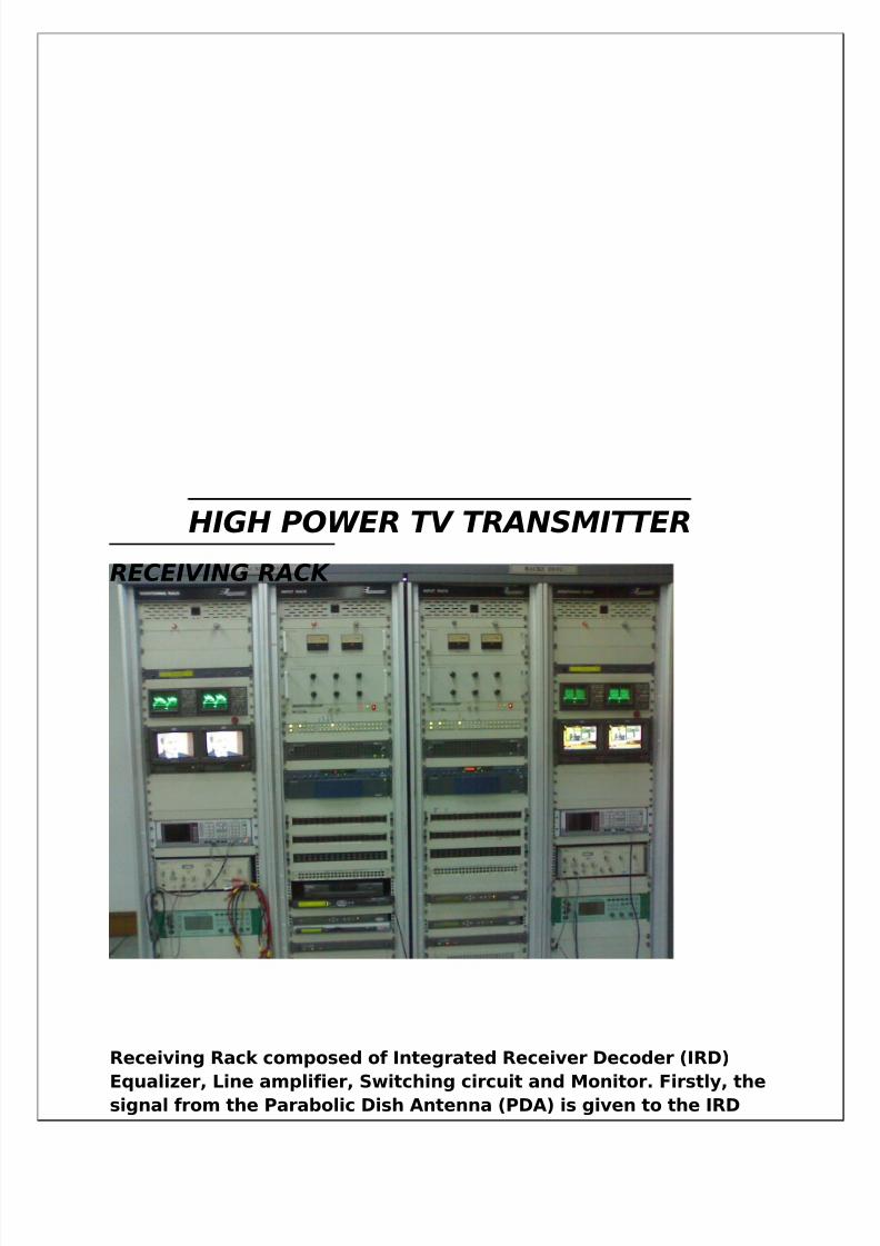
HIGH POWER TV TRANSMITTER
RECEIVING RACK
Receiving Rack composed of Integrated Receiver Decoder (IRD)
Equalizer, Line amplifier, Switching circuit and Monitor. Firstly, thesignal from the Parabolic Dish Antenna (PDA) is given to the IRD
5/14/2018 Best Final Ddk Hsr Both - slidepdf.com
http://slidepdf.com/reader/full/best-final-ddk-hsr-both 40/54
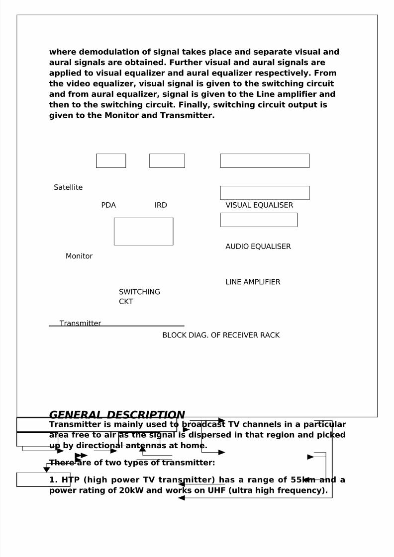
where demodulation of signal takes place and separate visual and
aural signals are obtained. Further visual and aural signals are
applied to visual equalizer and aural equalizer respectively. From
the video equalizer, visual signal is given to the switching circuit
and from aural equalizer, signal is given to the Line amplifier andthen to the switching circuit. Finally, switching circuit output is
given to the Monitor and Transmitter.
GENERAL DESCRIPTIONTransmitter is mainly used to broadcast TV channels in a particular
area free to air as the signal is dispersed in that region and picked
up by directional antennas at home.
There are of two types of transmitter:
1. HTP (high power TV transmitter) has a range of 55km and a
power rating of 20kW and works on UHF (ultra high frequency).
PDA IRD VISUAL EQUALISER
AUDIO EQUALISER
LINE AMPLIFIER
SWITCHINGCKT
Satellite
Monitor
Transmitter
BLOCK DIAG. OF RECEIVER RACK
5/14/2018 Best Final Ddk Hsr Both - slidepdf.com
http://slidepdf.com/reader/full/best-final-ddk-hsr-both 41/54
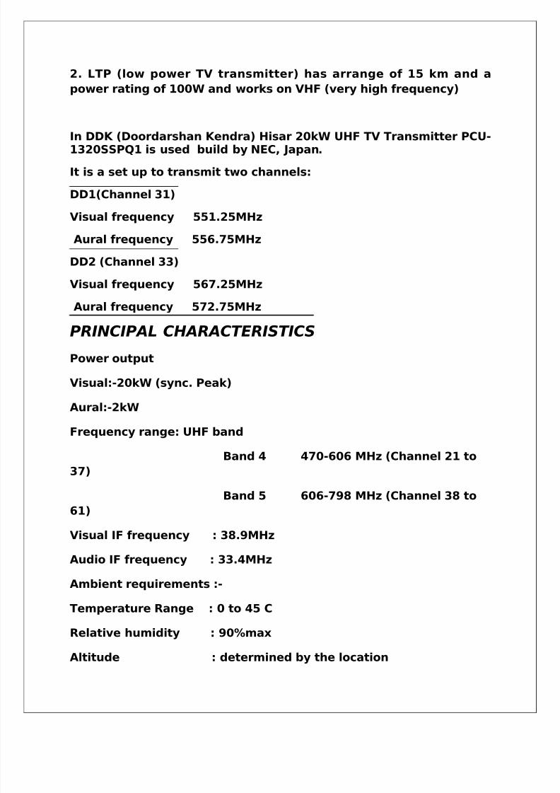
2. LTP (low power TV transmitter) has arrange of 15 km and a
power rating of 100W and works on VHF (very high frequency)
In DDK (Doordarshan Kendra) Hisar 20kW UHF TV Transmitter PCU-1320SSPQ1 is used build by NEC, Japan.
It is a set up to transmit two channels:
DD1(Channel 31)
Visual frequency 551.25MHz
Aural frequency 556.75MHz
DD2 (Channel 33)
Visual frequency 567.25MHz
Aural frequency 572.75MHz
PRINCIPAL CHARACTERISTICS
Power output
Visual:-20kW (sync. Peak)
Aural:-2kW
Frequency range: UHF band
Band 4 470-606 MHz (Channel 21 to
37)
Band 5 606-798 MHz (Channel 38 to
61)
Visual IF frequency : 38.9MHz
Audio IF frequency : 33.4MHz
Ambient requirements :-
Temperature Range : 0 to 45 C
Relative humidity : 90%max
Altitude : determined by the location
5/14/2018 Best Final Ddk Hsr Both - slidepdf.com
http://slidepdf.com/reader/full/best-final-ddk-hsr-both 42/54
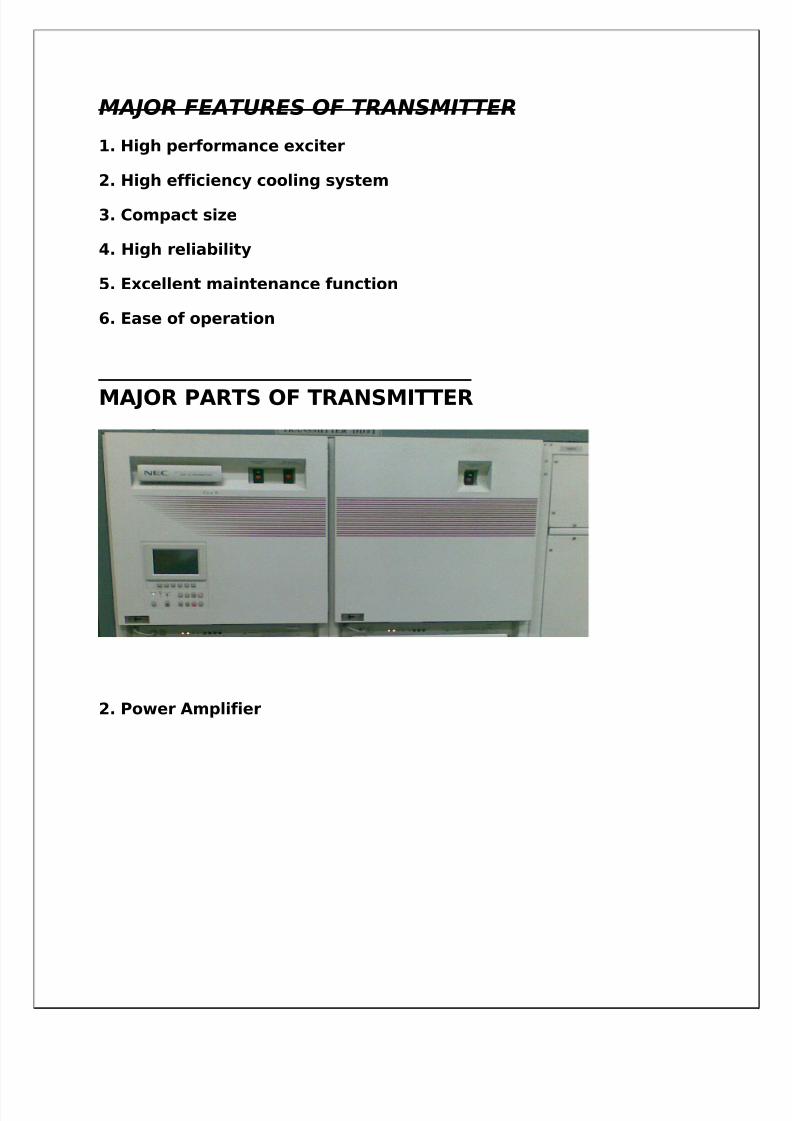
MAJOR FEATURES OF TRANSMITTER
1. High performance exciter
2. High efficiency cooling system
3. Compact size
4. High reliability
5. Excellent maintenance function
6. Ease of operation
MAJOR PARTS OF TRANSMITTER
1. Exciter
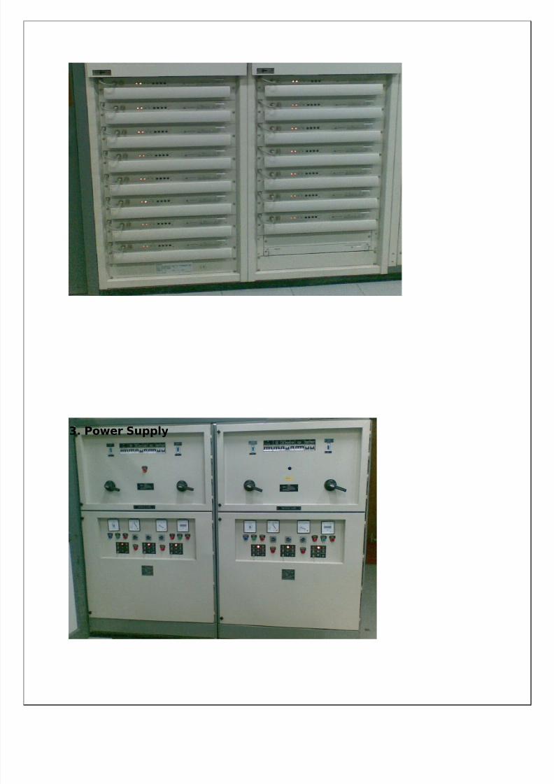
2. Power Amplifier
5/14/2018 Best Final Ddk Hsr Both - slidepdf.com
http://slidepdf.com/reader/full/best-final-ddk-hsr-both 43/54
3. Power Supply
5/14/2018 Best Final Ddk Hsr Both - slidepdf.com
http://slidepdf.com/reader/full/best-final-ddk-hsr-both 44/54
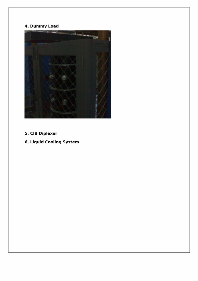
4. Dummy Load
5. CIB Diplexer
6. Liquid Cooling System
5/14/2018 Best Final Ddk Hsr Both - slidepdf.com
http://slidepdf.com/reader/full/best-final-ddk-hsr-both 45/54
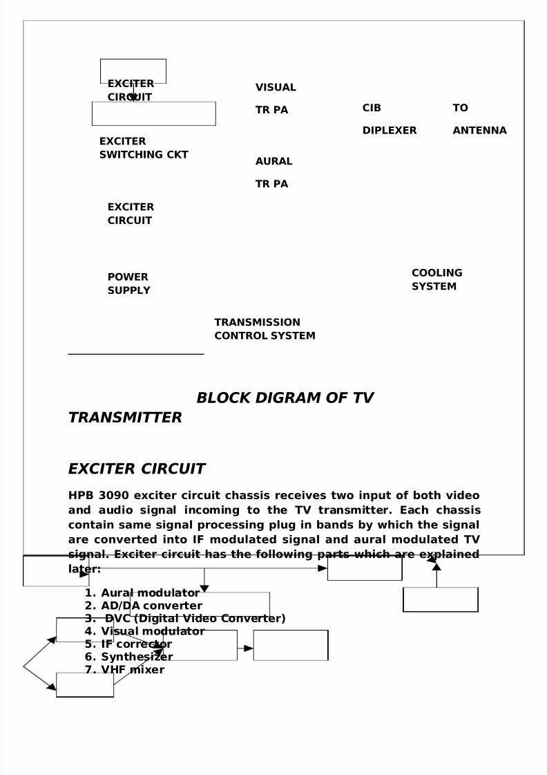
BLOCK DIGRAM OF TV
TRANSMITTER
EXCITER CIRCUIT
HPB 3090 exciter circuit chassis receives two input of both video
and audio signal incoming to the TV transmitter. Each chassis
contain same signal processing plug in bands by which the signal
are converted into IF modulated signal and aural modulated TVsignal. Exciter circuit has the following parts which are explained
later:
1. Aural modulator2. AD/DA converter3. DVC (Digital Video Converter)4. Visual modulator5. IF corrector6. Synthesizer7. VHF mixer
EXCITER
CIRCUIT
EXCITER
SWITCHING CKT
EXCITER
CIRCUIT
VISUAL
TR PA
AURAL
TR PA
CIB
DIPLEXER
TO
ANTENNA
POWER
SUPPLY
COOLINGSYSTEM
TRANSMISSION
CONTROL SYSTEM
5/14/2018 Best Final Ddk Hsr Both - slidepdf.com
http://slidepdf.com/reader/full/best-final-ddk-hsr-both 46/54
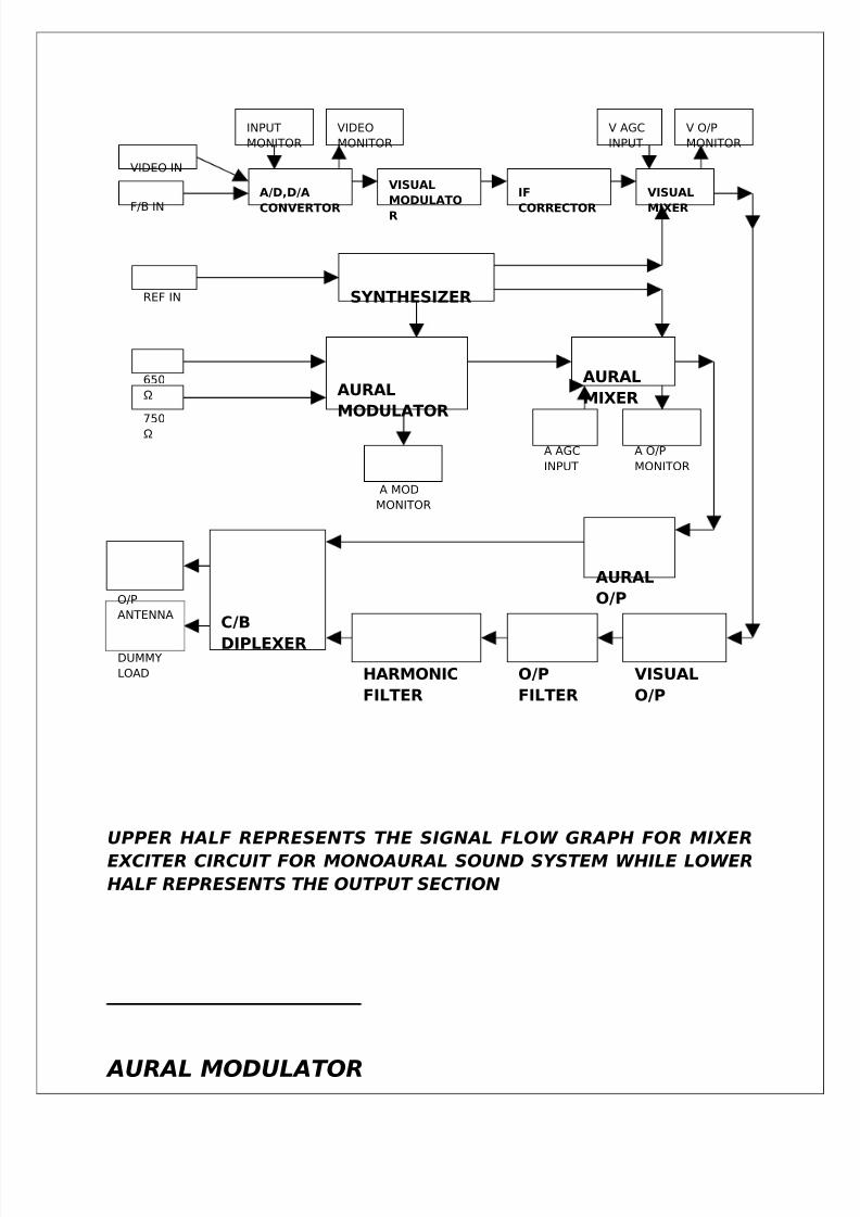
UPPER HALF REPRESENTS THE SIGNAL FLOW GRAPH FOR MIXER
EXCITER CIRCUIT FOR MONOAURAL SOUND SYSTEM WHILE LOWER
HALF REPRESENTS THE OUTPUT SECTION
AURAL MODULATOR
VIDEO IN
A/D,D/A
CONVERTOR
VISUAL
MODULATO
R
IF
CORRECTOR
VISUAL
MIXER
V O/P
MONITOR
V AGC
INPUT
VIDEO
MONITOR
INPUT
MONITOR
F/B IN
REF IN SYNTHESIZER
650
Ω AURAL
MODULATOR
AURAL
MIXER750
Ω
A O/P
MONITOR
A AGC
INPUT
A MOD
MONITOR
AURAL
O/P
VISUAL
O/P
O/P
FILTER
HARMONIC
FILTER
C/B
DIPLEXER
O/P
ANTENNA
DUMMY
LOAD
5/14/2018 Best Final Ddk Hsr Both - slidepdf.com
http://slidepdf.com/reader/full/best-final-ddk-hsr-both 47/54
It generates a frequency modulator and IF signal by modulating a
voltage controlled oscillator with an audio input. To fix average
frequency of the modulator oscillator at the reference input theautomatic phase controlled circuit is used.
DVC UNIT COMPENSATOR HPB 3103
It is composed of a non linear distortion compensating circuit,linear distortion compensating circuit, control unit etc, receives
the demodulated output signal of the transmitter and
automatically compensates for the distortion the output signal.
The non linear and linear circuits can be respectively bypassed.
AD/DA CONVERTER
The HPB-3102 AD-DA unit has functions that converts the
video i/p signal supplied to the exciter into a PCM signal and
sends the PCM signal to a unit for digital correction (HPB-
3103 DVC) and which converts the video PCM signal after the
digital correction into analog video signal and supplies the
analog video signal to a visual modulator unit(HPB-3104
VMOD unit).
IF CORRECTOR
The HPB-3105 IF Corrector unit , generally used for correction
of nonlinear distortion generated in the PA stage ,enables
correction of DG and DP characteristics of visual signal. This
unit also contains a means to combine two modulated. IF
carriers of the visual and aural , allowing multiplex operation
transmitter.
5/14/2018 Best Final Ddk Hsr Both - slidepdf.com
http://slidepdf.com/reader/full/best-final-ddk-hsr-both 48/54
UHF MIXER
In HPB-3107 UHF Mixer unit, the local signal produced by
quadruple and IF signal is applied to a DBM to obtain an RFsignal. The RF signal is passed through filters (BPF and NF) to
separate out only the specified channel. Then, by amplifying
the signal to the required level, an RF signal of +20dBm is
obtained at the o/p. By applying AGC to the IF signal, the o/p
power of the transmitter is maintained at a constant level
.The BPF and NF are adjusted from the front side.
I/F Input Level=+10dBm
LO Input Level=+10dBm
Output Level=+20dBm
Bandwidth=8MHz
Visual modulator
The HPB-3104 visual modulator unit is intended to convert a
base band video signal into a modulated IF signal with the
ring modulator in which the IF carrier is also phase modulated
by a processed video signal to pre-correct the incidental
carrier phase modulation (ICPM).
SYNTHESIZER
The HPB-3108 Synthesizer unit generates two signals, visual
IF (VIF) and local
frequency.
5/14/2018 Best Final Ddk Hsr Both - slidepdf.com
http://slidepdf.com/reader/full/best-final-ddk-hsr-both 49/54
Power amplifier
The UA-2000QC-S is a Power amplifier of peak output 2000 W,
which is used for visual of analog Transmitter.
The UA-2000QC-S is possible to use as a power amplifier of
1200W output for aural of analog Transmitter or a power
amplifier of 500W for digital Transmitter as well.
Power supply
Power supply is a switching type of stabilized power supply
that receives 400V AC (3 phase) and supplies +24~32V DC to
loads.
3-db coupler
3-dB Coupler is used for application listed below:
• Distributing one signal(2 o/p)
• Coupling 2 signals(1 o/p)
• Mixing 2 signals(2 o/p)
•Switching over 2 signals(2 o/p)
5/14/2018 Best Final Ddk Hsr Both - slidepdf.com
http://slidepdf.com/reader/full/best-final-ddk-hsr-both 50/54
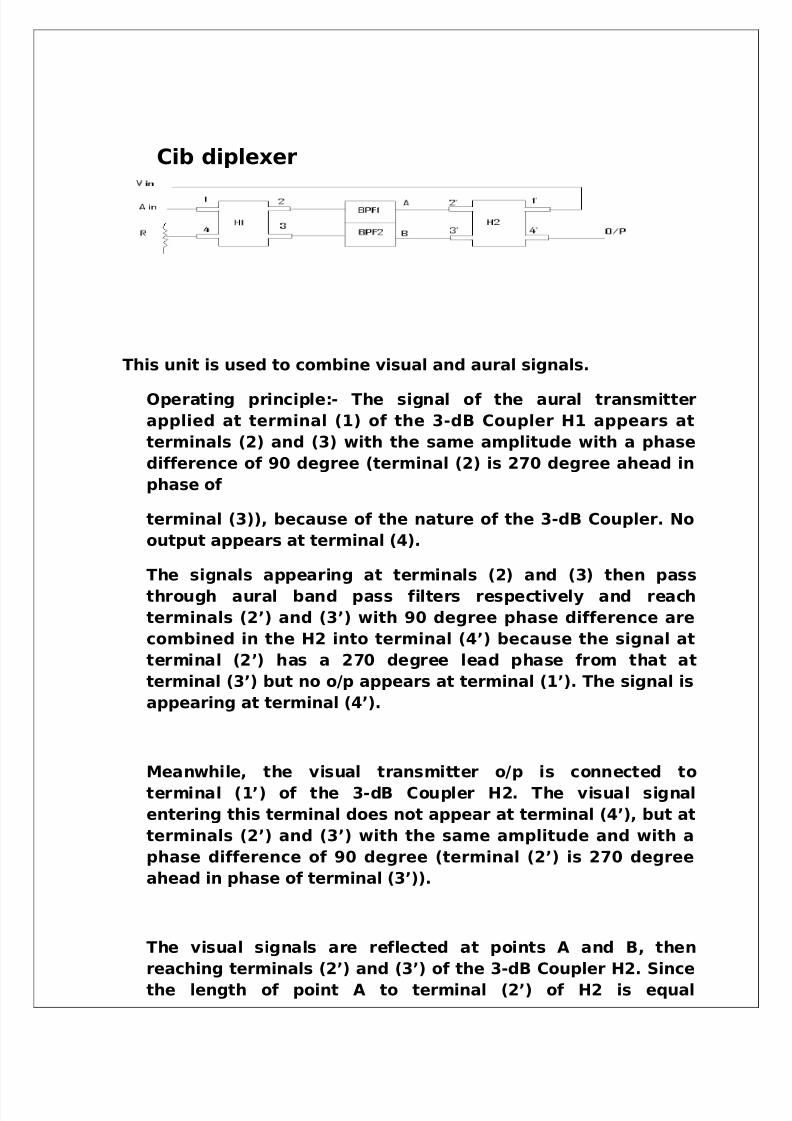
Cib diplexer
This unit is used to combine visual and aural signals.
Operating principle:- The signal of the aural transmitter
applied at terminal (1) of the 3-dB Coupler H1 appears at
terminals (2) and (3) with the same amplitude with a phase
difference of 90 degree (terminal (2) is 270 degree ahead in
phase of
terminal (3)), because of the nature of the 3-dB Coupler. No
output appears at terminal (4).
The signals appearing at terminals (2) and (3) then pass
through aural band pass filters respectively and reach
terminals (2’) and (3’) with 90 degree phase difference are
combined in the H2 into terminal (4’) because the signal at
terminal (2’) has a 270 degree lead phase from that at
terminal (3’) but no o/p appears at terminal (1’). The signal is
appearing at terminal (4’).
Meanwhile, the visual transmitter o/p is connected to
terminal (1’) of the 3-dB Coupler H2. The visual signal
entering this terminal does not appear at terminal (4’), but at
terminals (2’) and (3’) with the same amplitude and with a
phase difference of 90 degree (terminal (2’) is 270 degree
ahead in phase of terminal (3’)).
The visual signals are reflected at points A and B, then
reaching terminals (2’) and (3’) of the 3-dB Coupler H2. Since
the length of point A to terminal (2’) of H2 is equal
5/14/2018 Best Final Ddk Hsr Both - slidepdf.com
http://slidepdf.com/reader/full/best-final-ddk-hsr-both 51/54
electrically to that of point B to terminal (3’) of H2, the visual
signal returning to terminal (2’) of H2 is combined with that
to terminal (3’) because of the nature of 3-dB Coupler. Then
the combined visual signal appears at terminal (4’).
Liquid cooling system
This system is composed of pump rack and heat exchanger in
addition to the transmitter.
The pump rack is equipped with automatically switch able
dual pumps thus realizing high redundancy accuracy. This
pump rack is composed of pumps, a coolant tank, control
panel and power supply. Two pumps are used pump A and
pump B for each rack out of which one is used at one time.
In a region where outside air temperature never becomes
lower than 0 degree Celsius purified or distilled water is used
as coolant having PH range =6.5~8.5.
In a region where temperature is less than 0 degree Celsius
antifreeze use pure ethylene glycol containing no impurity
diluted with water and mix it with the corrosion inhibitor.
5/14/2018 Best Final Ddk Hsr Both - slidepdf.com
http://slidepdf.com/reader/full/best-final-ddk-hsr-both 52/54
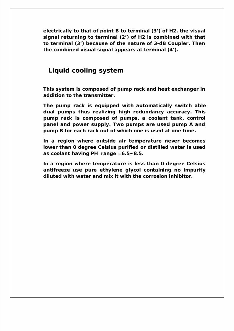
ANTENNA
ANTENNA TYPE
Doordarshan /TV transmitting antenna is a Radio Frequency
system Pty Ltd (RFS) transmitting antenna model PHP322D. The
antenna is capable of multi channel operation & can accept a no. of
UHF TV transmitters within the 470-860 MHz range. The antenna
has been optimized in the factory for channels E31 (550-558 MHz)& E33 (566-574 MHz) & the frequency range 500-650 MHz
5/14/2018 Best Final Ddk Hsr Both - slidepdf.com
http://slidepdf.com/reader/full/best-final-ddk-hsr-both 53/54
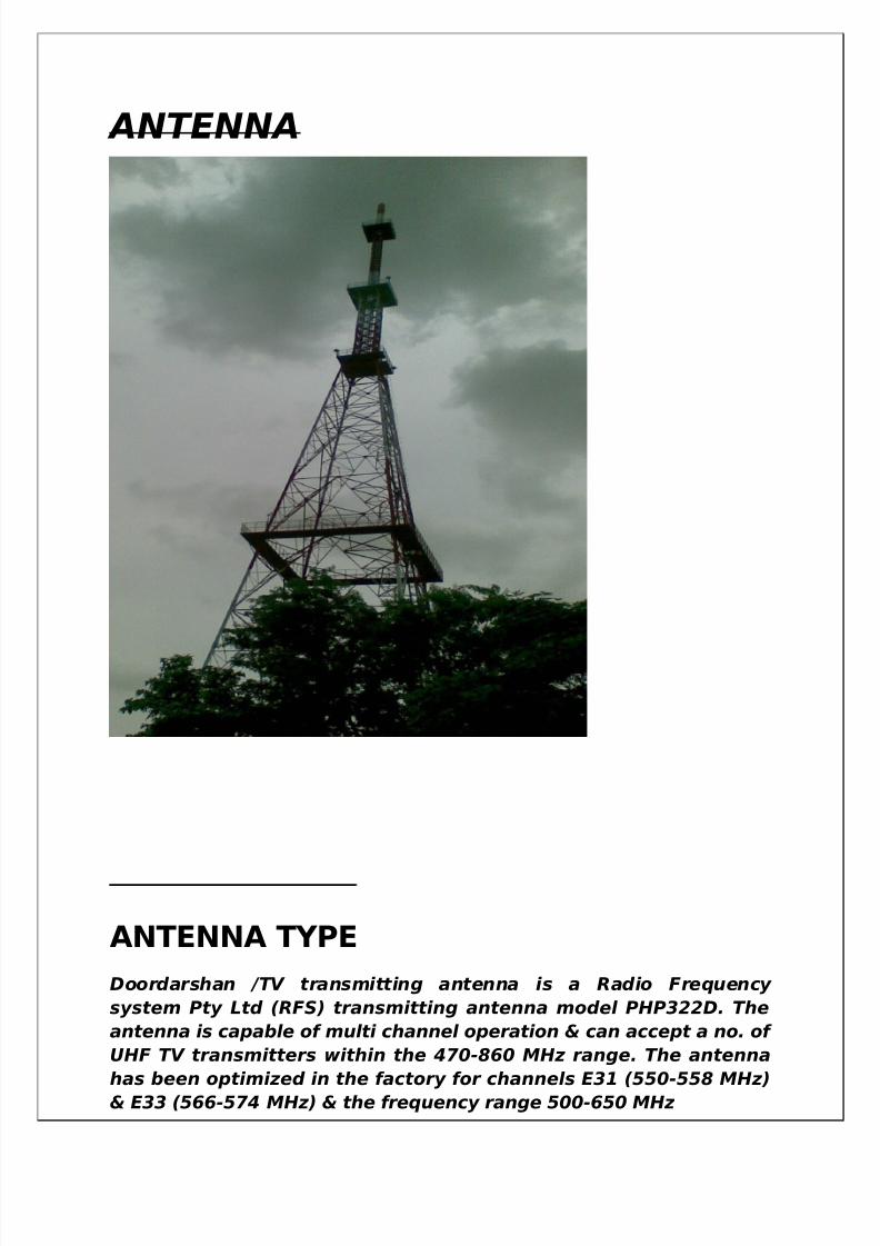
ANTENNA IDENTIFICATIONPHP 32 D
Panel Antenna Horizontal
Polarized
Thirty two panels
Four Sides
ANTENNA INPUT CAPACITY
The system has been designed to accommodate 2*20 KW PAL
transmitters into half antenna.
MECHANICAL CONSTRUCTION
The array consists of a series of thirty two panel antenna. There
are two antenna ladders to access the antenna for installation &
maintenance. Lighting protection is to be installed on top of
column.
ENVIRONMENTAL CONDITIONS
• Temperature operating : -10 c to 50 c
•Design wind speed : 240 Kilometer per hour
• Total Wind Load @ 50 m/s: Normal to Face =25 Ka
ELECTRICAL CHARACTERISTICS
• Model : PHP32D
• Operating Frequency range: CHE31 (550-558 MHz)
CHE33 (566-574MHz)
• Polarization : Horizontal

5/14/2018 Best Final Ddk Hsr Both - slidepdf.com
http://slidepdf.com/reader/full/best-final-ddk-hsr-both 54/54
• Max Power rating : 40 KW peak sync into Half
antenna
• Design Power rating : 2*20 KW Peak Sync