belihul oya mini hydropower plant project under ltl holdings (pvt) ltd
TRANSCRIPT

ACKNOWLEDGEMENTS
I would like to express my sincere thanks to the Industrial Training and Career Guidance Unit of
the Faculty of Engineering University of Peradeniya, and to National Apprentice and Industrial
Training (NAITA) for arranging this training opportunity for us. I sincerely appreciate their effort,
paying their valuable time to arrange this training session for ourselves and to make our industrial
training a successful one.
I must further thank, to the chairman with the all of the staff and laborers to success my training and to
improve my knowledge about the several sections in their company, LTL holdings (Pvt) Ltd.
Specially I offer my sincere thanks to the Project manager of the Belihul oya minihydro power plant,
Senior mechanical Engineer Mr. Sudath Kularathna who was in-charge of us during the training
session. Actually it was a strange experience for me at the beginning of the training period and I could
spend valuable and pleasurably 10 weeks with the help of all the personnel who have given the support
and the assistance in completing my industrial training session.
E.M.K.S. Edirisooriya
Faculty of Engineering
University of Peradeniya

ii
CONTENTS
Acknowledgements i
Contents ii
List of Figures v
List of Tables vii
Chapter 1 INTRODUCTION
1.1 Introduction of Contractor 1
1.2 Introduction to mini-hydro power 2
1.3 Salient Features of Belihul Oya mini hydropower Plant 2
Chapter 2 INSTALLATION OF THE FRANCIS TURBINE
2.1 Basic steps for installation 3
2.2 Turbine casing installation 3
2.3 Generator base frame mounting 5
2.4 Generator placement 6
2.5 Draft tube elbow mounting 7
2.6 Draft tube cone mounting 8
2.7 Butterfly valve and dismantling joint mounting 8
2.8 Installation of pipings 9
2.9 Second concrete works 10
2.10 Runner mounting 10
2.11 Inlet pipe erection 11
2.12 Second concrete works at penstock 12
2.13 Completing installation 13

iii
Chapter 3 HYDRAULIC POWER UNIT
3.1 Assembling the hydraulic power unit 14
3.2 Assemble the external gear unit 16
Chapter 4 INSPECTION OF PENSTOCK
4.1 Penstocks 18
4.2 Penstock joints 19
4.3 Inspection procedures of the penstock 23
Chapter 5 CRANE GANTRIES INSTALLATION
5.1 Track joints, wheel running and guidance surfaces 24
5.2 Dimensional and geometrical tolerances of tracks for top running
and underslung cranes 24
5.3 Measurement of crane tracks 27
Chapter 6 CONCLUSIONS 28

iv
LIST OF FIGURES
Figure 2.1 Turbine casing adjustment 4
Figure 2.2 fixed connections 4
Figure 2.3 Base frame of the generator 5
Figure 2.4 Base plate of the generator 6
Figure 2.5 Generator placement 6
Figure 2.6 Fixed the turbine and generator with turbine cap 6
Figure 2.7 Draft tube elbow 7
Figure 2.8 Draft tube cone mounting 8
Figure 2.9 Butterfly valve and dismantling joint mounting 9
Figure 2.10 Pipe lines installation 9
Figure 2.11 second concrete woks 10
Figure 2.12 Before inlet pipe erection 11
Figure 2.13 After inlet pipe erection 12
Figure 2.14 Second concrete works at penstock 12
Figure 2.15 After completing the installation 13
Figure 3.1 hydraulic power unit 14
Figure 3.2 assembling the hydraulic power unit 15
Figure 3.3 Hydralic system 16
Figure 3.4 The external gear unit 16
Figure 3.5 The direction of the rotation of the external gear 17
Figure 4.1 Components of the penstock assembly 18
Figure 4.2 Flanged joints 19

v
Figure 4.3 Spigot and socket joints 20
Figure 4.4 Mechanical joints 21
Figure 4.5 Welded joints 22
Figure 4.6 Welding joint of the penstock 22
Figure 4.7 Welding the penstock joint 23
Figure 5.1 Top running cranes 24
Figure 5.2 Underslung cranes 25
Figure 5.3 Permissible deviation of track straightness in lateral plane 26
Figure 5.4 Permissible deviation of track straightness in vertical plane 27
Figure 5.5 Permissible transverse inclinations of tracks 27
Figure 5.6 Crane installation 27

vi
LIST OF TABLES
Table 1.1 Salient Features of Belihul Oya mini hydropower Plant 2

1
CHAPTER 1: INTRODUCTION
1.1 Introduction of Contractor
LTL Projects (Pvt) Ltd which is a subsidiary of LTL Holdings (Pvt) Ltd plays a key role with a
diverse portfolio which encompasses total responsibility for Engineering, Procurement and
Construction of Thermal, wind and Medium scale Hydro power plants from conceptual design through
to commissioning. vast experience gathered through implementation of previous power projects has
open up the opportunity for the company to enter into emerging markets Internationally as a Power
Plant development as well as Transmission Infrastructure solutions.
Technology drives their business- it speeds schedules, cuts costs and ensures quality.
Their area of involvement in power plant projects include, but are not limited to:
Project planning
Project management
Complete Civil works including pile Construction, Equipment foundations, Buildings, Fuel &
Water storage tanks and other infrastructure development.
Mechanical Erection and installation plant and equipment
Complete installation of Electrical system including
Power transformer installations
Main switchgear and switch yard installation
Electrical panel installation and commissioning
Power and control cabling
Protection and PLC systems
Building Electrification
LTL projects is the only Sri Lankan company which has developed the competency to construct on
turnkey basis, high voltage (33kV, 132kV, 220kV) overhead power transmission lines. The company
has constructed most of the transmission lines in the country since 1996, The scope covered consists
of:
Project management
Designing of towers
Designing of line profile
Development of drawings & documentation
Procurement of line components

2
Civil construction
Tower erection
Stringing of conductors
Commissioning & Testing
The company has in-house competency in designing transmission line towers and line profiles. The
latest software is being used for this purpose to add value to the customer by increasing the reliability
of the power system.
1.2 Introduction to mini-hydro power
Hydropower is energy from water sources such as the ocean, rivers and waterfalls. “Mini hydro”
means which can apply to sites ranging from a tiny scheme to electrify a single home, to a few
hundred kilowatts for selling into the national grid. Small- scale hydro-power is one of the most cost-
effective and reliable energy technologies to be considered for providing clean electricity generation.
The key advantages of small hydro are,
High efficiency (70% - 90%) by far the best of all energy technologies.
High capacity factor.
High level of predictability, varying with annual rainfall patterns.
A good correlation with demand.
It is also environmental benign small hydro is in most cases ‘run-of-river’, in other words any dam or
barrage is quite small, usually just a weir, and little or no water is stored.
1.3 Salient Features of Belihul Oya minihydropower Plant
Table 1.1: Salient Features of Belihul Oya mini hydropower Plant
Parameter Belihuloya Minihydro Power Plant
Design Capacity 2.2 MW
Design Head 167 m
Design Flow 1.6 Weir 1.5m height 18m length
Canal 1.2m × 1.2m (W×H), 850m length
Penstock 1000mm diameter, 700m length
Machine type & configuration Turgo Impulse, 2×1.1 MW
Transformer 2×1.6 MVA, 00/33000V
Transmission line 4km Tower line with Lynx conductor

3
CHAPTER 2: INSTALLATION OF THE FRANCIS TURBINE
2.1 Basic steps for installation
At first step main dimensions of the concrete station should be checked. All dimensions should be
exact and low tolerance with related drawings.
There are some dimensions that have important role in erection procedure and should be exactly
checked. These dimensions are as following items:
Dimension of all recesses for turbine, generator base, draft tube and valve.
All areas (for both turbines) should be at the same level and these parameters should be
checked exactly.
Especially for generators with base plate:
Check dimensions of base plate foundation
Check distance of generator base plate holes in appendance of turbine base frame hole.
Other checks
All areas have to be cleaned carefully and free of any waste before starting installation
process.
Check if cable channels of complete plant according to layout drawings.
2.2 Turbine casing installation
After checking all related dimensions and remove all extra materials from base surfaces equipment
erection could be continued as follow:
Move turbines as sent by GHE into rectangular hole and align it by use of surveyor’s
optical lever meter and machined water level meter.
Center lines of turbine casing has to be adjusted precisely according to layout drawing.
Consider a gap of approximately 100-150 mm (indicated in general layout drawing) to
ground level.
Measure distance between turbines in compare with set value.
Control of parallel adjustment of both turbines.
Control exact alignment in relation to inlet pipes.

4
Drill holes in first concrete in order to set glue anchor bolts into first concrete.
Set anchor bolts and fix with special glue.
Adjust the turbine by using two nuts on anchor bolts in such a way, that it is adjusted via
surveyor’s optical lever meter and machined water level meter exactly in horizontal
position, measured in both directions.
Control of same height level of both turbines.
Check again all relevant measurements and proof once more, that distance of both turbines
is according to set value (bifurcation pipe distance)
Figure 2.1 Turbine casing adjustment
After adjusting the mentioned dimensions, turbine casing should be fixed at relevant position. For
this aim, fixed connection between turbine casing with help of rods around could be used.
Figure 2.2 Fixed connections
Finally main dimensions should be checked one more time.
5
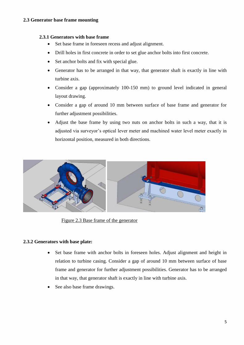
2.3 Generator base frame mounting
2.3.1 Generators with base frame
Set base frame in foreseen recess and adjust alignment.
Drill holes in first concrete in order to set glue anchor bolts into first concrete.
Set anchor bolts and fix with special glue.
Generator has to be arranged in that way, that generator shaft is exactly in line with
turbine axis.
Consider a gap (approximately 100-150 mm) to ground level indicated in general
layout drawing.
Consider a gap of around 10 mm between surface of base frame and generator for
further adjustment possibilities.
Adjust the base frame by using two nuts on anchor bolts in such a way, that it is
adjusted via surveyor’s optical lever meter and machined water level meter exactly in
horizontal position, measured in both directions.
Figure 2.3 Base frame of the generator
2.3.2 Generators with base plate:
Set base frame with anchor bolts in foreseen holes. Adjust alignment and height in
relation to turbine casing. Consider a gap of around 10 mm between surface of base
frame and generator for further adjustment possibilities. Generator has to be arranged
in that way, that generator shaft is exactly in line with turbine axis.
See also base frame drawings.
6
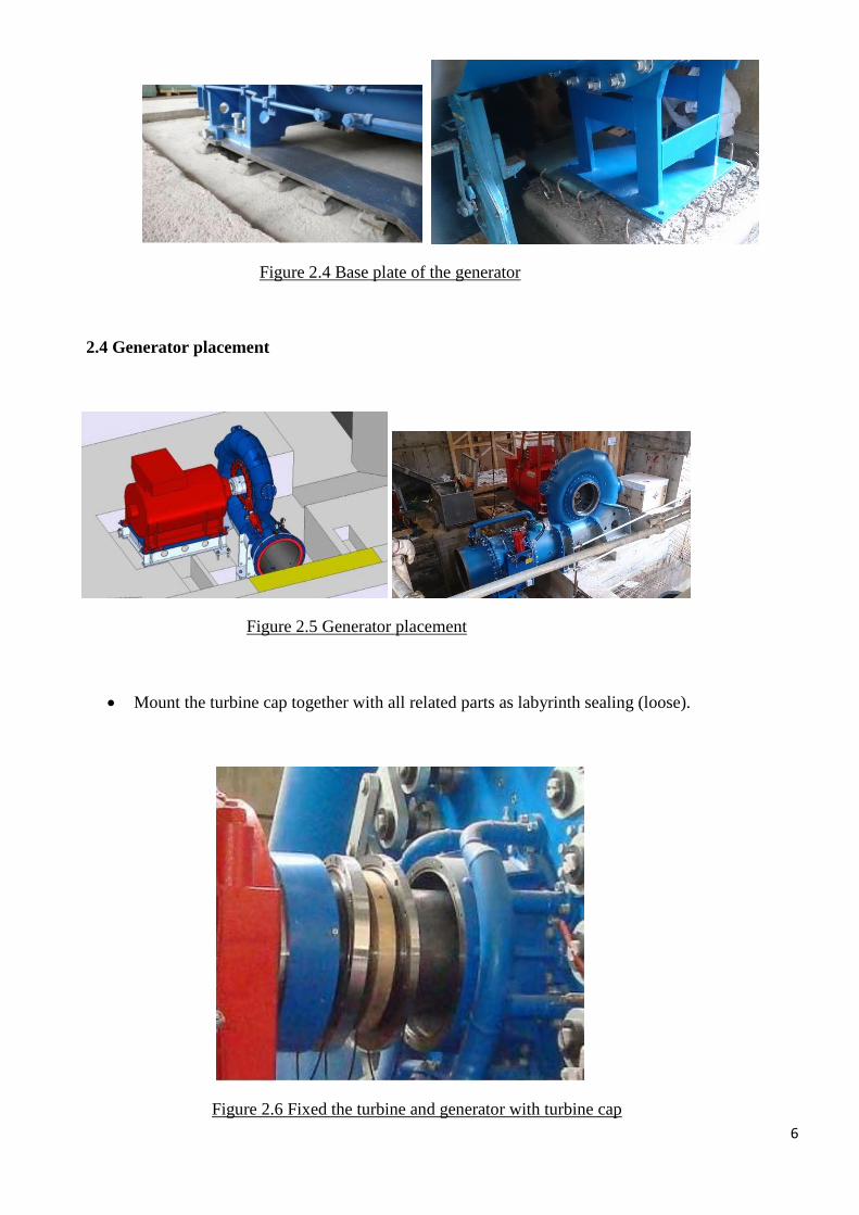
Figure 2.4 Base plate of the generator
2.4 Generator placement
Figure 2.5 Generator placement
Mount the turbine cap together with all related parts as labyrinth sealing (loose).
Figure 2.6 Fixed the turbine and generator with turbine cap
7
Place generator onto frame and adjust it accordingly by use of adjusting screws.
Consider a gap of around 10 mm between surface of base frame and generator for further
adjustment possibilities. Use thin plates for precise adjustment between generator and
baseplate.
Adjust generator turbine under center line.
Specially generator has to be leveled in horizontal plane exactly. And its shaft should be adjusted
concentrically with casing flange. Also axial dimension between generator and turbine should be
checked and adjusted according to outline drawings.
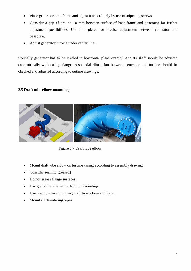
2.5 Draft tube elbow mounting
Figure 2.7 Draft tube elbow
Mount draft tube elbow on turbine casing according to assembly drawing.
Consider sealing (greased)
Do not grease flange surfaces.
Use grease for screws for better demounting.
Use bracings for supporting draft tube elbow and fix it.
Mount all dewatering pipes

8
2.6 Draft tube cone mounting
Figure 2.8 Draft tube cone mounting
Mount draft tube on elbow according to assembly drawings.
Consider sealing (greased)
Do not grease flange surfaces.
Use grease for screws for better demounting.
Use bracings for supporting draft tube and fix it.
2.7 Butterfly valve and dismantling joint mounting
At this stage valve will be installed in its position correctly.
These are the valve manufacturer instructions.
Arrange dismantling joint in medium positions.
9
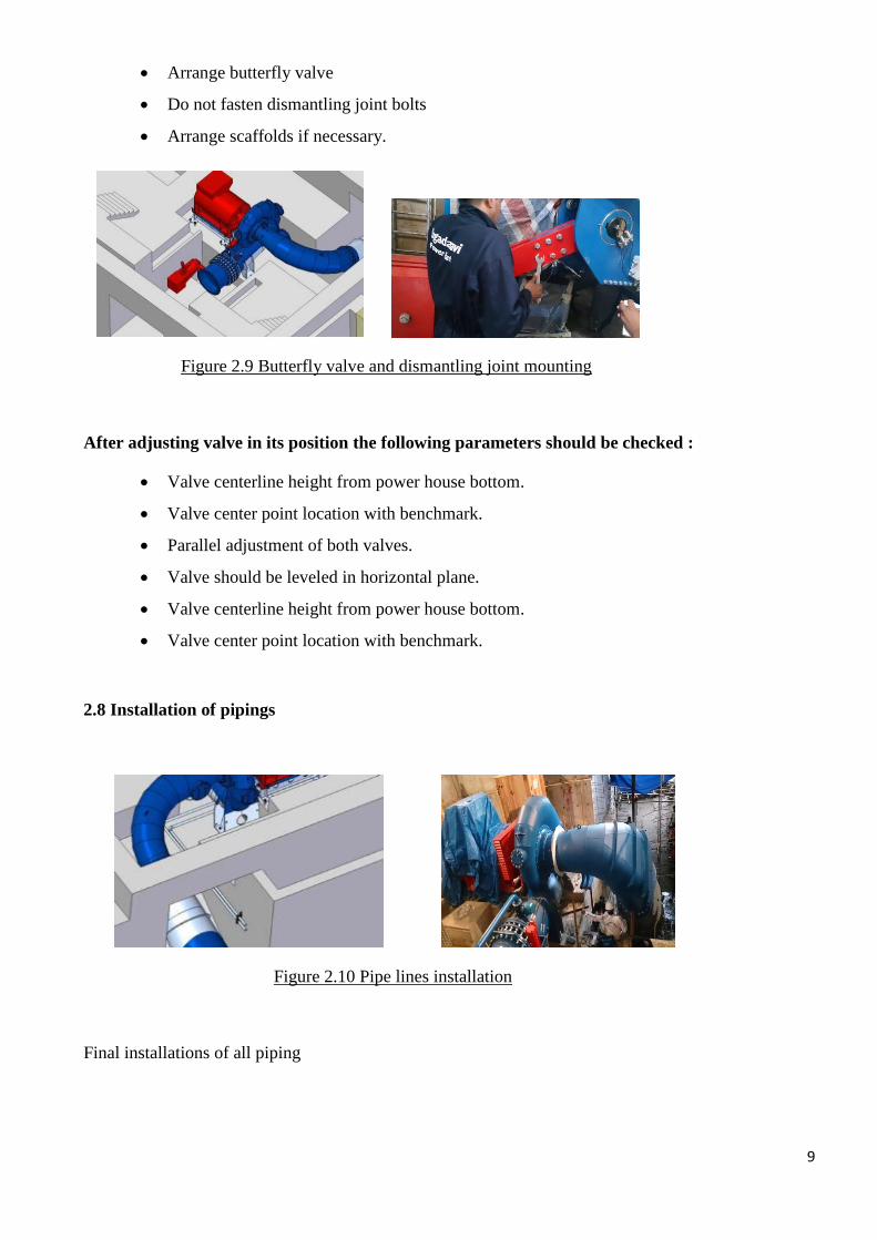
Arrange butterfly valve
Do not fasten dismantling joint bolts
Arrange scaffolds if necessary.
Figure 2.9 Butterfly valve and dismantling joint mounting
After adjusting valve in its position the following parameters should be checked :
Valve centerline height from power house bottom.
Valve center point location with benchmark.
Parallel adjustment of both valves.
Valve should be leveled in horizontal plane.
Valve centerline height from power house bottom.
Valve center point location with benchmark.
2.8 Installation of pipings
Figure 2.10 Pipe lines installation
Final installations of all piping

10
2.9 Second concrete works
After approval of GHE supervisor all components can be set into concrete.
Figure 2.11 Second concrete woks
Use adequate concrete quality.
Fill in concrete in 2 steps.(1-2 days pause)
Use concrete vibrators.
Pay attention to fill generator base frame holes carefully, also by use of concrete vibrators.
Consider sufficient time for concrete hardening before going ahead (depends on concrete
quality)
And also during hardening of first turbine setting second machine can be arranged in the same way.
2.10 Runner mounting
After complete hardening of concrete, all relevant dimensions should be checked again carefully. For
runner mounting it is necessary to demount draft tube elbow again.
Check center alignment of turbine shaft to ensure correct adjustment by use of dial
indicators rotating on both casing runner rings considering parallelism and centric
adjustment.
Adjust generator No 1 (8300 kVA) 0,45 mm under center line.
Adjust generator No 2 (5100 kVA) 0,40 mm under center line.
Consider exact depth of inserted shaft according to assembly drawings.

11
Mount runner onto generator shaft by use of pumps and high oil pressure according to turbine manual.
For mounting the Francis runner on the turbine shaft need two high pressure hydraulic squeezers are
needed. With one pump the hub will be squeezed axial against the conical shaft-bushing. The second
pump is used for the expansion of the hub. After reaching the calculated ascertained axial slip-on path,
the pressure of both pumps can be released and the hub is actuated by connection ought to be filled
with grease before fixing the runner-cap. The mounting of the Francis runner is only possible from
draft tube side.
Check all gaps of runner carefully
Fix runner cap
After complete fixing of runner and checked all relevant measurements according to assembly
drawings, draft tube elbow can be mounted again.
2.11 Inlet pipe erection
Figure 2.12 Before inlet pipe erection
Mount inlet flange + tube onto valve according to assembly drawing.
Mount bypass pipe.
Weld inlet pipe on tube and connect it to bifurcation pipe.

12
Figure 2.13 After inlet pipe erection
After finishing connection to inlet pipe dismantling joint can be fixed.
2.12 Second concrete works at penstock
After approval of GHE supervisor penstock can be set into concrete.
Figure 2.14 Second concrete works at penstock
Use adequate concrete quality.
Use concrete vibrators.

13
Consider sufficient time for concrete hardening before going ahead. (depends on concrete
quality )
2.13 Completing installation
Complete mounting of labyrinth sealing considering all gaps according to assembly drawing.
Place lubrication unit and mount all lubrication and cooling pipes.
Mount hydraulic unit and foresee all necessary pipe connections according to hydraulic
schemata.
Finish installation according to assembly drawing.
Check carefully tightness of all screws, pipes and bolts.
Figure 2.15 After completing the installation

14
CHAPTER 3: HYDRAULIC POWER UNIT
3.1 Assembling the hydraulic power unit
To assemble the hydraulic power unit we should proceed these things :
Position the hydraulic power unit or the assembly as specified in the product specific
documentation.
Ensure that the footprint contact associated with mounting is consistent.
Level the hydraulic power unit so that its longitudinal and transverse axes are horizontal.
Prevent possible bouncing by suitable means. As a example height adjustment of the feet,
insertion of shims, packers
Securely fix the product at the mounting positions specified in the product specific
documentation.
As the preparation want to remove the blanking plugs and flange covers (colored plastic) and replace
them with pressure-resistant fittings or flanges.
We should observe the manufacturer’s installation instructions for the screw fittings to
ensure there is no external leakage. We recommend the use of fitting with elastic seals.
Before installing, clean the connection lines to the hydraulic system, ensuring they are free from dirt,
scales, chippings, etc. welded pipes must be blank on the inside and flushed.
Figure 3.1 hydraulic power unit
15
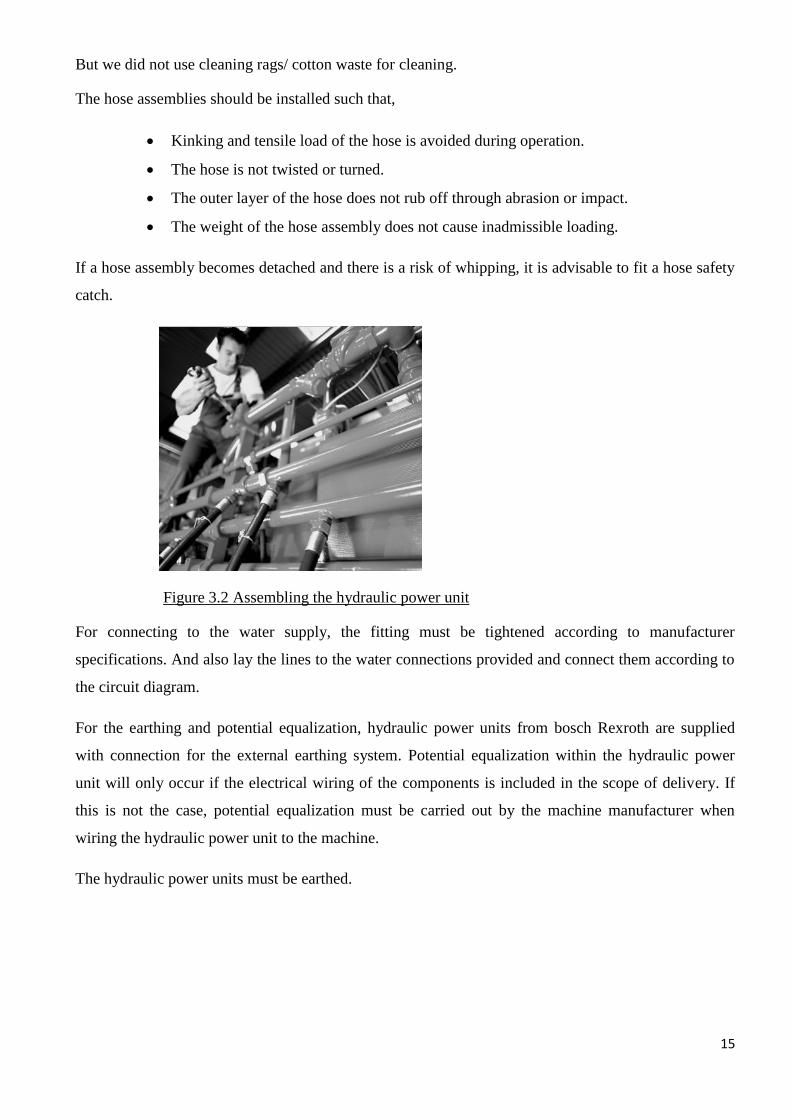
But we did not use cleaning rags/ cotton waste for cleaning.
The hose assemblies should be installed such that,
Kinking and tensile load of the hose is avoided during operation.
The hose is not twisted or turned.
The outer layer of the hose does not rub off through abrasion or impact.
The weight of the hose assembly does not cause inadmissible loading.
If a hose assembly becomes detached and there is a risk of whipping, it is advisable to fit a hose safety
catch.
Figure 3.2 Assembling the hydraulic power unit
For connecting to the water supply, the fitting must be tightened according to manufacturer
specifications. And also lay the lines to the water connections provided and connect them according to
the circuit diagram.
For the earthing and potential equalization, hydraulic power units from bosch Rexroth are supplied
with connection for the external earthing system. Potential equalization within the hydraulic power
unit will only occur if the electrical wiring of the components is included in the scope of delivery. If
this is not the case, potential equalization must be carried out by the machine manufacturer when
wiring the hydraulic power unit to the machine.
The hydraulic power units must be earthed.

16
Figure 3.3 Hydralic system
3.2 Assemble the external gear unit
The installation location and position of an external gear unit essentially determine the procedures
during installation.
The case of the external gear unit must be filled and remain filled with hydraulic fluid at
commissioning and during operation.
To achieve favorable noise values, decouple all connecting lines (suction, pressure and case
drain ports) from the tank using flexible element.
Generally in all installation positions and locations a minimum suction pressure, specified for pumps :
minimum suction pressure ≥ 0.7 bar
Figure 3.4 The external gear unit
To assemble the external gear unit with a coupling:
Assemble the specified coupling half to the drive or output shaft of the external gear unit
according to the coupling manufacturer’s specifications. There must be radial and axial forces
acting on the shaft and coupling sleeve.

17
Always we observed the maximum torques. These values can be found in the relevant Y-sheets
and catalog sheets.
For flexible coupling,
The maximum radial run out of shaft spigot is 0.2 mm.
For coupling sleeves,
The coupling sleeve must be free to move axially.
Maintain the spacing between drive shaft and output shaft.
Oil-bath or oil-mist lubrication is necessary.
Then the installation location was cleaned and free of dirt and contaminants.
Clamp the coupling hub onto the drive shaft or ensure permanent lubrication of the drive shaft.
This prevents the formation of frictional corrosion and the associated wear.
Transport the external gear unit to the installation location and assemble the coupling onto the
drive or output drive according to the coupling manufacturer’s specifications.
But the external gear unit should not be tightened until the coupling had been correctly
assembled.
Fixed the external gear unit at the installation location. The details on the required tools and
tightening torques for the fixing screws can be obtained from the machine or system
manufacturer.
For bell housing installation, we checked the coupling axial play through the bell
window according to the manufacturer’s notes.
For flange installation, aligned the external gear unit support with the drive or output
drive.
Figure 3.5 The direction of the rotation of the external gear
18
CHAPTER 4: INSPECTION OF PENSTOCK
4.1 Penstocks
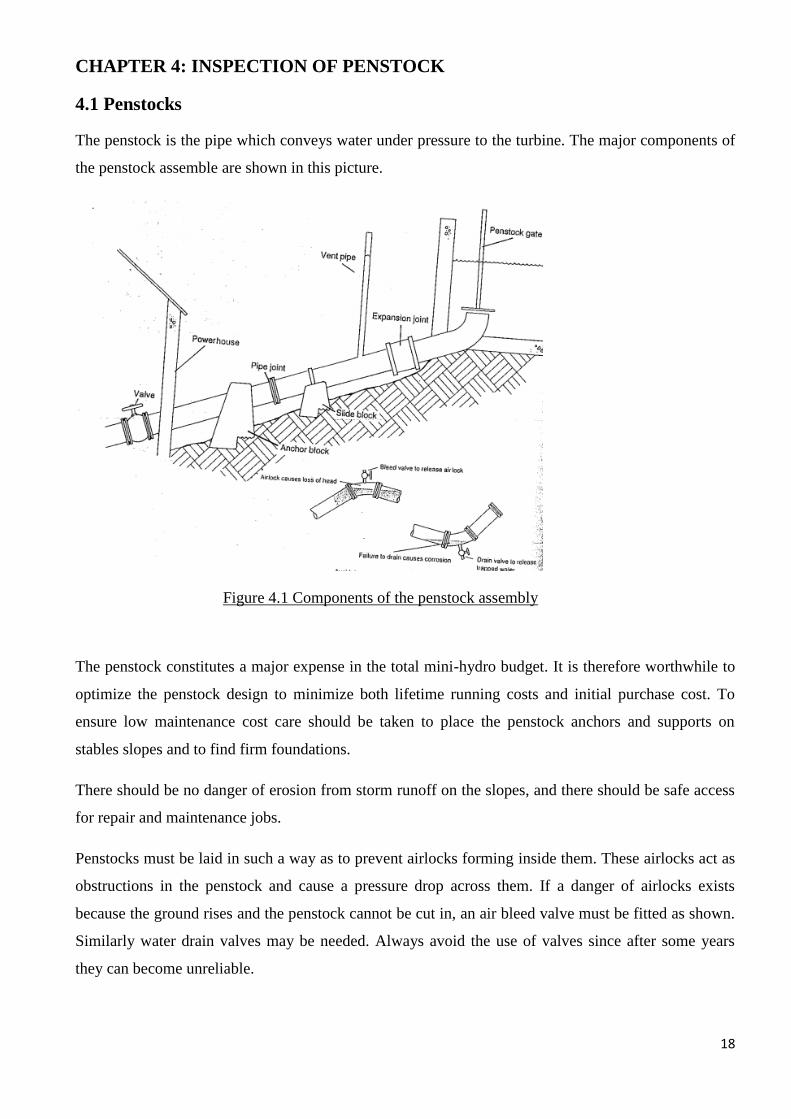
The penstock is the pipe which conveys water under pressure to the turbine. The major components of
the penstock assemble are shown in this picture.
Figure 4.1 Components of the penstock assembly
The penstock constitutes a major expense in the total mini-hydro budget. It is therefore worthwhile to
optimize the penstock design to minimize both lifetime running costs and initial purchase cost. To
ensure low maintenance cost care should be taken to place the penstock anchors and supports on
stables slopes and to find firm foundations.
There should be no danger of erosion from storm runoff on the slopes, and there should be safe access
for repair and maintenance jobs.
Penstocks must be laid in such a way as to prevent airlocks forming inside them. These airlocks act as
obstructions in the penstock and cause a pressure drop across them. If a danger of airlocks exists
because the ground rises and the penstock cannot be cut in, an air bleed valve must be fitted as shown.
Similarly water drain valves may be needed. Always avoid the use of valves since after some years
they can become unreliable.

19
4.2 Penstock jointing
Pipes are generally supplied in standard lengths, and have to be jointed together on site. These are
many ways of doing this, and the following factors should be considered when choosing the best
jointing system for a particular scheme.
Suitability for chosen pipe material.
Skill level of personal installing the pipes.
Whether any degree of joint flexibility is required.
Relative costs
Ease of installation.
Methods of pipe jointing fall roughly into four categories,
Flanged
Spigot and socket
Mechanical
Welded
4.2.1 Flanged joints
Flanges are fitted to each end of individual pipes during manufacture, and each flange is then bolted to
the next during installation. A gasket or other packing material, usually rubber, is necessary between
each flange of a pair. Flange jointed pipes are easy to install. But flanges can add to the cost of the
pipe. Flange joints are generally used on mild steel pipes, and occasionally to join ductile iron. Flanges
should conform to some recognized standard, for instance, British Standard (BS) or International
Organization for standardization (ISO). Flange joints do not allow any ‘flexibility’ or deflection.
Figure 4.2 Flanged joints

20
4.2.2 Spigot and socket joints
Spigot and socket joints are made by either fitting a collar to, or increasing the diameter during
manufacture of, one end of each pipe, such that the internal diameter of the collar or increased internal
diameter of the pipe is the same as the external diameter of the pipe. The plain end of each pipe can
thus be pushed into the collar or ‘socket’ in the next. A good seal is required between each pipe
section, and this is achieved by either providing a rubber seal or using a special glue called solvent
cement, depending on the material of which the pipes are made. Previously a seal was achieved by
packing the joint with lead chippings, but this method is now only used to repair existing old joints in
case iron penstocks.
Rubber seal joints fall generally into two types:
‘O’ ring seals
Single or multiple ‘V’ lip seals
They are generally used to joint ductile iron, PVC, or GRP pipes. Rubber seal joints generally permit a
few degrees of deflection.
Figure 4.3 Spigot and socket joints
A few precautions are necessary when installing this type of joints:
The seal must be clean before assembly.
A special lubricant must be used. Never use an oil-based grease as this will cause the seal to
rot. If the special lubricant is not available, soap may be used.
For pipes over 50 mm, always use clamps and a ratchet pulley to ‘pull’ the two halves of the
joint together.
Ensure that the joint is properly aligned before final coupling. ‘V’ ring seal joints are
extremely difficult and often impossible to take apart.

21
Solvent cement welded spigot and socket joints are used on PVC pipes. A special chemical paste,
which dissolves the plastic material, is applied to the spigot half of the joint, which is then inserted into
the socket. The chemical action ‘welds’ the two halves together.
4.2.3 Mechanical joints
Mechanical joints are rarely used on penstocks because of their cost. In some cases their extra cost is
justified by savings made in installation cost and because they allow slight misalignments in the
penstock. This facilitates installation and allows later movement of anchors/foundations to occur
without causing under stress in the penstock.
One important application is for joining pipes of different material or where a slight deflection in the
penstock is required that does not warrant installing a bend. Some types of mechanical joints cannot
take any strain in the direction of the pipe and have to be restrained by anchor blocks.
Figure 4.4 Mechanical joints
4.2.4 Welded joints
Welded joints are used on mild steel penstocks and, using special techniquws, on M/HDPE. One
advantage of welding on site is that changes in the direction of the pipe can be accommodated without
preparation of a special bend section. Mild steel pipes are brought to the site in standard lengths, and
then welded together, generally using an arc welder, on site. It is a relatively cheap method, but has the
disadvantae of needing skilled site site personnel, and the problems of getting an arc welder and power
supply into remote and difficult terrain.

22
Figure 4.5 Welded joints
It is essential to have a competent person doing the welding to ensure sound joints. The major
disadvantage is that a site-welded steel pipe usually ends up with a low quality finish with respect to
corrosion-protection.
Figure 4.6 Welding joint of the penstock

23
Figure 4.7 Welding the penstock joint
4.3 Inspection procedures of the penstock
The procedures for inspection of a penstock or pressure conduit are listed like this:
Perform an initial assessment which includes a thorough visual examination of the following
items: penstock shell condition, welds, bolts and rivets, expansion joints and sleeve-type
couplings, air valves and vents, control valves, manholes and other penetrations, anchor blocks
and supports, appurtenances, lining and coatings, and instrumentation.
Recorded the penstock shell thickness measurements using non-destructive examination
methods at selected locations along the penstock.
Perform a detailed assessment using NDE techniques for specific items of concern that were
observed during the visual examination.
Simulate the emergency control system operation to ensure the emergency gates or valve will
close and that documentation exists to indicate they will completely close.
Perform load rejection tests for comparison against hydraulic transient analysis results and
design criteria to ensure safe operating conditions.
Readjust the governor to establish a safe wicket gate timing to prevent over-pressurization of
the penstock and to ensure maximum response capability.
Have design personnel evaluate the data obtained during the penstock inspection. This
evaluation should typically include tasks associated with data and stress analysis and a
determination if the penstock is in accordance with defined acceptance criteria.

24
CHAPTER 5: CRANE GANTRIES INSTALLATION
5.1 Track joints, wheel running and guidance surfaces
Any misalignment of running faces or gaps occurring between sections of track will have an adverse
effect on the performance and life of the crane.
Joints arrangement should ensure accuracy in the alignment of running faces or guidance faces to
provide a smooth transition path for the wheel between sections of track.
Track running and guidance faces should be free of obstruction and should be left unpainted. These
faces should also be free from damage and pitting or other surface defects.
5.2 Dimensional and geometrical tolerances of tracks for top running and underslung cranes
Multiple span cranes running on three or more tracks require special consideration, and tolerances and
levels for them should be subject for deflection of the supporting structure from which the tracks are
suspended.
Figure 5.1 Top running cranes

25
Figure 5.2 Underslung cranes
5.2.1 Tolerance on span
The tolerance on span should be as follows,
S ≤ 3 mm where S ≤ 15 mm
S ≤ 3 +0.25 (S-15) mm where S > 15 mm
S max. =15 mm
5.2.2 Misalignment of track running surfaces in the vertical plane.
The tolerance on track misalignment should be as follows
H ≤ 0.001 S
H max. = 10 mm
5.2.3 Tolerance on track width (underslung only)
The tolerance on track width should be as follows,
W = 0.025 W

26
5.2.4 Track straightness tolerances
Permissible deviation in the lateral plane.
For the total length of track, the maximum lateral deviation from the straight line mean datum should
not exceed 10 mm.
The straight line mean datum is the line about which deviations of truck on each side will be equal,
when summated over the whole length of track.
Figure 5.3 Permissible deviation of track straightness in lateral plane
Local lateral deviation at any point of the track should not be greater than L/ 2000, measured over a
length of not less than 2 m on a line parallel to the straight line mean datum.
Permissible deviation in the vertical plane.
For the total length of the track, the maximum vertical deviation from the theoretical datum line should
not exceed 10 mm. The theoretical datum line may be the true horizontal line or a theoretical camber
line.
Local vertical deviation at any point of the track should not be greater than L/2000, measured over a
length of not less than 2 m on a line parallel to the theoretical datum.

27
Figure 5.4 Permissible deviation of track straightness in vertical plane
5.2.5 Running surface permissible traverse inclination from the horizontal datum position.
The maximum permissible traverse inclination from the horizontal datum position should be like this.
Figure 5.5 Permissible transverse inclinations of tracks
5.3 Measurement of crane tracks
When measuring crane tracks, calibrated steel measuring tapes should be used. It is important that the
readings obtained are corrected to allow for sag in the tape and for temperature variation. All track
measurements for a particular crane should be made with the same measuring tape and the same
applied tension force.
Figure 5.6 Crane installation

28
CHAPTER 6 – CONCLUSION
I was able to get my second training at LTL Holdings (Pvt) Ltd plays a key role with a diverse
portfolio which encompasses total responsibility for Engineering, Procurement and Construction of
Thermal, wind and Medium scale Hydro power plants from conceptual design through to
commissioning. It has branches in Bangladesh and Uganda. It was a great opportunity to be an
engineering trainee there because I could study and learn about the mini hydro power Plant and its
main components. Therefore I could get valuable experiences. I could understand the responsibility of
a job when I was working in the belihul oya site.
During my training session I learned about how to deal with the top management as well as the
workers, how to keep our communication with employees while doing the projects, how much
engineering was used for practical applications and what are the things I need to develop in my future
career.