behaviour of flat slab rcc structure under earthquake loading · behaviour of flat slab rcc...
TRANSCRIPT
Behaviour of Flat Slab Rcc Structure Under
Earthquake Loading
Sanjay P N1, Mahesh Prabhu K
2, Umesh S S
3
1-Post Graduate Student, Department of civil Engineering, SCEM, Mangalore
Karnataka, India, 575007
2-Associate Professor, Department of civil Engineering, GEC, Ramnagara
Karnataka, India, 571511
3-Associate Professor, Department of civil Engineering, SCEM, Mangalore
Karnataka, India, 575007
Abstract—As flat slab building structures are significantly
more flexible than traditional concrete frame/wall or frame
structures, thus becoming more vulnerable to seismic loading.
Therefore, the characteristics of the seismic behavior of flat slab
buildings suggest that additional measures for guiding the
conception and design of these structures in seismic regions are
needed. To improve the performance of building having flat slabs
under seismic loading, provision of flat slab with drop and
without drop is proposed in the present work. The object of the
present work is to compare the behaviour of multi-storey
buildings having flat slabs with drops and without drop on the
performance of these two types of buildings under seismic forces.
And different types of zones and different type of soils condition
as per IS code Provision Present work provides a good source of
information on the parameters storey shear, base shear, storey
drift, and maximum bending moment at column
Keywords— Flat slab with drop and without drop, Storey
drift, Storey shear, Base shear, Maximum bending
moment.ETABS
I. INTRODUCTION
Reinforced concrete has been used for building construction
since the middle of the 19th century, first for some parts of
buildings, and then for the entire building structure.
Reinforced concrete is a major construction material for civil
infrastructure in current society. Construction has always
preceded the development of structural design methodology.
Dramatic collapse of buildings has been observed after each
disastrous earthquake, resulting in loss of life.
A flat slab is a reinforced concrete slab supported directly
by concrete columns without the use of beams. Reinforced
concrete flat slabs are one of the most popular floor systems
used in residential buildings, car parks and many other
structures. They represent elegant and easy-to-construct floor
systems. Flat slabs are favored by both architects and clients
because of their aesthetic appeal and economic advantage.
Reinforced concrete flat slabs are commonly used in
construction as they provide a number of benefits to the
designer including: 1.Thin sections allowing for greater roof
heights and lighter floors, 2.Exposed ceilings, 3.Flexible
column arrangements, this is more difficult to achieve for a
beam-column design,4.Fast and cheap construction using
simple formwork.
However, flat slabs have a lower stiffness in comparison to a
beam-column floor plan which can lead to relatively large
deflections. In addition to this, the shear capacity can also be
reduced in particular around the column head where large
shear forces can develop. There are two main failure modes of
flat slabs: 1.Flexural Failure and 2.Punching Shear Failure.
Slabs are designed to fail by flexural failure, the failure mode
is ductile therefore giving relatively large deflections under
excessive loading, also cracks will appear on the bottom
surface before failure occurs. These signs allow the problem to
be addressed before failure occurs.
Punching shear failure by comparison is a brittle failure mode
when shear reinforcement is not added, meaning failure will
occur before significant deflections take place, in addition to
this any cracks that will develop before failure will propagate
from the top surface. Since this surface is typically covered, it
is unlikely that there will be sufficient warning available
before failure occurs.
II. PROBLEM FORMULATION
In our study we are focusing on the behaviour of flat slab
rcc structure of two different types one is with drops and
another one is without drop which involves its behaviour for
earthquake condition. As it is clear from previous literature that
flat slab structure are unstable for seismic forces, we are
analytically investigating the effect of flat slab generally with
various site condition and in various earthquake zones. The
analysis method considering for the Response spectrum
method as per IS provision. And by using ETABS software
also
III. PARAMETERS CONSIDERED
The parameters considered in the performance evaluation are
as under
1386
International Journal of Engineering Research & Technology (IJERT)
IJERT
IJERT
ISSN: 2278-0181
www.ijert.orgIJERTV3IS051624
Vol. 3 Issue 5, May - 2014
1. Flat Slab Framed Structures subjected to seismic
forces.
2. Flat Slab Framed Structures subjected to different
zones and different soil condition as per IS 1893
(Part-1): 2002
3. Analysis method Equivalent static analysis (ESA) and
Response spectrum analysis (RSA).
4. Maximum Bending moment and Storey Drift in the
buildings with and without Drop.
5. Storey Shear and Design base shear in the buildings
with and without Drop.
IV.MODELING AND ANALYSIS
Description of building:
Type of structure: Multi-storey Flat slab RCC structure with and without Drops
Occupancy: Office Building
Number of stories: 6(G+5)
Ground storey height: 3.5m
Intermediate storey height: 3.5m
Model design: One of the objectives of this model designing is
to ensure that the models represent the characteristics of
commercial buildings. These days, high-rise buildings are
different in shape, height and functions. This makes each
building characteristics different from each others. There are
some standards for each kind of high-rise buildings, such as
residential, official and commercials. However, for model
designing, main factors such as grid spacing, floor shape, floor
height and column section were considered. Two buildings
with equal number of stories, with 6(G+5) story having same
floor plan of 77 m × 55m dimensions were considered for this
study. The floor plans were divided into seven by five bays in
such a way that center to center distance between two grids is
11 meters and 11 meters respectively.
Model 1: Building having flat slab without drops
Model 2: Building having flat slab with drops
The modeling of the structure has been done using the
structural software ETABS as
per the data given below:
Design Parameters
Type of soil: Soil type 1 (Hard soil) and Soil type 2 (Medium
soil)
Zones: Zone-2 and Zone-3 and Zone-4
Materials
Grade of Concrete: M25
Density of Concrete: 25kN/m2
Modulus of Elasticity of concrete: 5000√fck (As per IS
456:2000[11], pp16)
Member dimensions
CornerBeamSizes:BM300X900mm,BM1000X750mm,BM15
00X900mm,BM200X900mm,BM350X1000mm,BM200X100
0mm,BM300X750mm,BM200X750mm,BM350X750mm,BM
1000X900mm,BM600X900mm
Column Sizes: 1000X1000mm and 1000X1500mm
Slab Thickness: 275mm
Wall Thickness: 250mm
Shear Wall Thickness: 250mm
Drop Thickness: 500mm
Method of dynamic analysis:
Building with regular or nominally irregular plan
configuration may be modeled as a system of masses lumped
at floor levels with each mass having one degree of freedom,
that of lateral displacement in the direction under
consideration. Undamped free vibration analysis of entire
building modeled as spring – mass model shall be performed
using appropriate masses and elastic stiffness of the structural
system to obtain natural periods (T) and mode shapes {f} of
those of its modes of vibration that needs to be considered.
The number of modes to be used should be such that the sum
of total of modal masses of all modes considered is at least
90% of total seismic mass
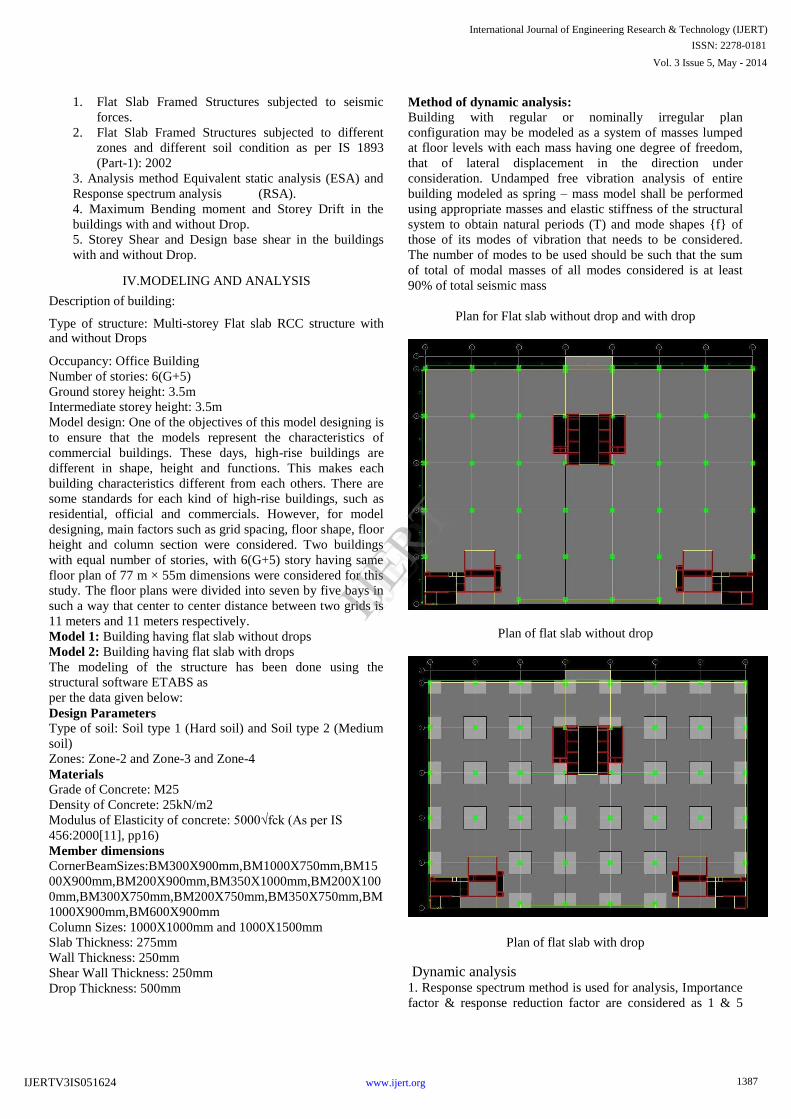
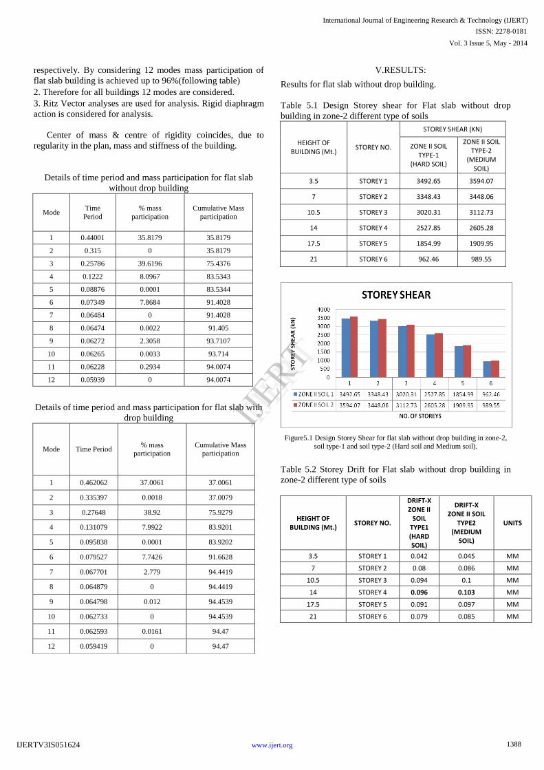
Plan for Flat slab without drop and with drop
Plan of flat slab without drop
Plan of flat slab with drop
Dynamic analysis 1. Response spectrum method is used for analysis, Importance
factor & response reduction factor are considered as 1 & 5
1387
International Journal of Engineering Research & Technology (IJERT)
IJERT
IJERT
ISSN: 2278-0181
www.ijert.orgIJERTV3IS051624
Vol. 3 Issue 5, May - 2014
respectively. By considering 12 modes mass participation of
flat slab building is achieved up to 96%(following table)
2. Therefore for all buildings 12 modes are considered.
3. Ritz Vector analyses are used for analysis. Rigid diaphragm
action is considered for analysis.
Center of mass & centre of rigidity coincides, due to
regularity in the plan, mass and stiffness of the building.
Details of time period and mass participation for flat slab
without drop building
Mode Time
Period
% mass
participation
Cumulative Mass
participation
1 0.44001 35.8179 35.8179
2 0.315 0 35.8179
3 0.25786 39.6196 75.4376
4 0.1222 8.0967 83.5343
5 0.08876 0.0001 83.5344
6 0.07349 7.8684 91.4028
7 0.06484 0 91.4028
8 0.06474 0.0022 91.405
9 0.06272 2.3058 93.7107
10 0.06265 0.0033 93.714
11 0.06228 0.2934 94.0074
12 0.05939 0 94.0074
Details of time period and mass participation for flat slab with
drop building
V.RESULTS:
Results for flat slab without drop building.
Table 5.1 Design Storey shear for Flat slab without drop
building in zone-2 different type of soils
HEIGHT OF BUILDING (Mt.)
STOREY NO.
STOREY SHEAR (KN)
ZONE II SOIL TYPE-1
(HARD SOIL)
ZONE II SOIL TYPE-2
(MEDIUM SOIL)
3.5 STOREY 1 3492.65 3594.07
7 STOREY 2 3348.43 3448.06
10.5 STOREY 3 3020.31 3112.73
14 STOREY 4 2527.85 2605.28
17.5 STOREY 5 1854.99 1909.95
21 STOREY 6 962.46 989.55
Figure5.1 Design Storey Shear for flat slab without drop building in zone-2,
soil type-1 and soil type-2 (Hard soil and Medium soil).
Table 5.2 Storey Drift for Flat slab without drop building in
zone-2 different type of soils
HEIGHT OF BUILDING (Mt.)
STOREY NO.
DRIFT-X ZONE II
SOIL TYPE1 (HARD SOIL)
DRIFT-X ZONE II SOIL
TYPE2 (MEDIUM
SOIL)
UNITS
3.5 STOREY 1 0.042 0.045 MM
7 STOREY 2 0.08 0.086 MM
10.5 STOREY 3 0.094 0.1 MM
14 STOREY 4 0.096 0.103 MM
17.5 STOREY 5 0.091 0.097 MM
21 STOREY 6 0.079 0.085 MM
Mode Time Period % mass
participation Cumulative Mass
participation
1 0.462062 37.0061 37.0061
2 0.335397 0.0018 37.0079
3 0.27648 38.92 75.9279
4 0.131079 7.9922 83.9201
5 0.095838 0.0001 83.9202
6 0.079527 7.7426 91.6628
7 0.067701 2.779 94.4419
8 0.064879 0 94.4419
9 0.064798 0.012 94.4539
10 0.062733 0 94.4539
11 0.062593 0.0161 94.47
12 0.059419 0 94.47
1388
International Journal of Engineering Research & Technology (IJERT)
IJERT
IJERT
ISSN: 2278-0181
www.ijert.orgIJERTV3IS051624
Vol. 3 Issue 5, May - 2014
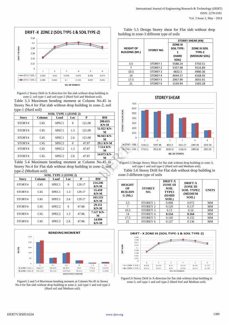
Figure5.2 Storey Drift in X-direction for flat slab without drop building in
zone-2, soil type-1 and soil type-2 (Hard Soil and Medium soil).
Table 5.3 Maximum bending moment at Column No.45 in
Storey No.4 for Flat slab without drop building in zone-2, soil
type-1 (Hard soil) SOIL TYPE 1 (ZONE 2)
Story Column Load Loc P BM
STORY4 C45 SPEC1 0 121.08 200.655
KN-M
STORY4 C45 SPEC1 1.3 121.08 51.922 KN-
M
STORY4 C45 SPEC1 2.6 121.08 96.943 KN-
M
STORY4 C45 SPEC2 0 47.87 29.1 KN-M
STORY4 C45 SPEC2 1.3 47.87 7.514 KN-
M
STORY4 C45 SPEC2 2.6 47.87 14.073 KN-
M
Table 5.4 Maximum bending moment at Column No.45 in
Storey No.4 for Flat slab without drop building in zone-2, soil
type-2 (Medium soil) SOIL TYPE 2 (ZONE 2)
Story Column Load Loc P BM
STORY4 C45 SPEC1 0 129.17 214.246
KN-M
STORY4 C45 SPEC1 1.3 129.17 55.418
KN-M
STORY4 C45 SPEC1 2.6 129.17 103.533
KN-M
STORY4 C45 SPEC2 0 47.86 29.151
KN-M
STORY4 C45 SPEC2 1.3 47.86 7.527 KN-
M
STORY4 C45 SPEC2 2.6 47.86 14.099
KN-M
Figure5.3 and 5.4 Maximum bending moment at Column No.45 in Storey No.4 for flat slab without drop building in zone-2, soil type-1 and soil type-2
(Hard soil and Medium soil).
Table 5.5 Design Storey shear for Flat slab without drop
building in zone-3 different type of soils
HEIGHT OF BUILDING (Mt.)
STOREY NO.
STOREY SHEAR (KN)
ZONE III SOIL TYPE-
1 (HARD SOIL)
ZONE III SOIL TYPE-2
(MEDIUM SOIL)
3.5 STOREY 1 5588.24 5750.51
7 STOREY 2 5357.48 5516.89
10.5 STOREY 3 4832.5 4980.36
14 STOREY 4 4044.57 4168.45
17.5 STOREY 5 2967.99 3055.91
21 STOREY 6 1539.94 1583.28
Figure5.5 Design Storey Shear for flat slab without drop building in zone-3,
soil type-1 and soil type-2 (Hard soil and Medium soil).
Table 5.6 Storey Drift for Flat slab without drop building in
zone-3 different type of soils
HEIGHT
OF
BUILDIN
G (Mt.)
STOREY
NO.
DRIFT-X
ZONE III
SOIL
TYPE1
(HARD
SOIL)
DRIFT-X
ZONE III
SOIL TYPE2
(MEDIUM
SOIL)
UNITS
3.5 STOREY 1 0.068 0.072 MM
7 STOREY 2 0.129 0.137 MM
10.5 STOREY 3 0.15 0.16 MM
14 STOREY 4 0.154 0.164 MM
17.5 STOREY 5 0.145 0.155 MM
21 STOREY 6 0.127 0.136 MM
Figure5.6 Storey Drift in X-direction for flat slab without drop building in zone-3, soil type-1 and soil type-2 (Hard Soil and Medium soil).
1389
International Journal of Engineering Research & Technology (IJERT)
IJERT
IJERT
ISSN: 2278-0181
www.ijert.orgIJERTV3IS051624
Vol. 3 Issue 5, May - 2014
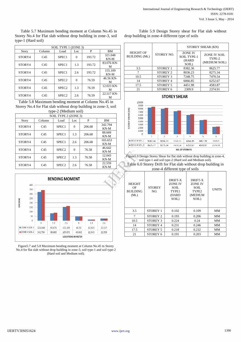
Table 5.7 Maximum bending moment at Column No.45 in
Storey No.4 for Flat slab without drop building in zone-3, soil
type-1 (Hard soil)
SOIL TYPE 1 (ZONE 3)
Story Column Load Loc P BM
STORY4 C45 SPEC1 0 193.72 321.048
KN-M
STORY4 C45 SPEC1 1.3 193.72 83.076 KN-
M
STORY4 C45 SPEC1 2.6 193.72 155.109
KN-M
STORY4 C45 SPEC2 0 76.59 46.56 KN-
M
STORY4 C45 SPEC2 1.3 76.59 12.023 KN-
M
STORY4 C45 SPEC2 2.6 76.59 22.517 KN-
M
Table 5.8 Maximum bending moment at Column No.45 in
Storey No.4 for Flat slab without drop building in zone-3, soil
type-2 (Medium soil) SOIL TYPE 2 (ZONE 3)
Story Column Load Loc P BM
STORY4 C45 SPEC1 0 206.68 342.794
KN-M
STORY4 C45 SPEC1 1.3 206.68 88.669 KN-M
STORY4 C45 SPEC1 2.6 206.68 165.653
KN-M
STORY4 C45 SPEC2 0 76.58 46.642
KN-M
STORY4 C45 SPEC2 1.3 76.58 12.043
KN-M
STORY4 C45 SPEC2 2.6 76.58 22.559
KN-M
Figure5.7 and 5.8 Maximum bending moment at Column No.45 in Storey No.4 for flat slab without drop building in zone-3, soil type-1 and soil type-2
(Hard soil and Medium soil).
Table 5.9 Design Storey shear for Flat slab without
drop building in zone-4 different type of soils
HEIGHT OF
BUILDING (Mt.) STOREY NO.
STOREY SHEAR (KN)
ZONE IV
SOIL TYPE-1 (HARD
SOIL)
ZONE IV SOIL
TYPE-2
(MEDIUM SOIL)
3.5 STOREY 1 8382.36 8625.77
7 STOREY 2 8036.23 8275.34
10.5 STOREY 3 7248.75 7470.54
14 STOREY 4 6066.85 6252.67
17.5 STOREY 5 4451.98 4583.87
21 STOREY 6 2309.9 2374.91
Figure5.9 Design Storey Shear for flat slab without drop building in zone-4,
soil type-1 and soil type-2 (Hard soil and Medium soil).
Table 6.0 Storey Drift for Flat slab without drop building in
zone-4 different type of soils
HEIGHT
OF
BUILDING (Mt.)
STOREY
NO.
DRIFT-X ZONE IV
SOIL
TYPE1 (HARD
SOIL)
DRIFT-X ZONE IV
SOIL
TYPE2 (MEDIUM
SOIL)
UNITS
3.5 STOREY 1 0.102 0.109 MM
7 STOREY 2 0.193 0.206 MM
10.5 STOREY 3 0.224 0.24 MM
14 STOREY 4 0.231 0.246 MM
17.5 STOREY 5 0.218 0.232 MM
21 STOREY 6 0.191 0.203 MM
1390
International Journal of Engineering Research & Technology (IJERT)
IJERT
IJERT
ISSN: 2278-0181
www.ijert.orgIJERTV3IS051624
Vol. 3 Issue 5, May - 2014
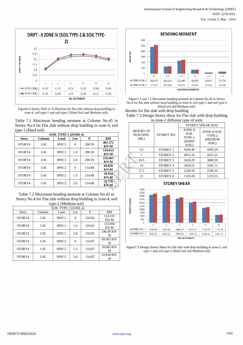
Figure6.0 Storey Drift in X-direction for flat slab without drop building in zone-4, soil type-1 and soil type-2 (Hard Soil and Medium soil).
Table 7.1 Maximum bending moment at Column No.45 in
Storey No.4 for Flat slab without drop building in zone-4, soil
type-1 (Hard soil) SOIL TYPE 1 (ZONE 4)
Story Column Load Loc P BM
STORY4 C45 SPEC1 0 290.59 481.572
KN-M
STORY4 C45 SPEC1 1.3 290.59 124.614
KN-M
STORY4 C45 SPEC1 2.6 290.59 232.663
KN-M
STORY4 C45 SPEC2 0 114.88 69.839
KN-M
STORY4 C45 SPEC2 1.3 114.88 18.034
KN-M
STORY4 C45 SPEC2 2.6 114.88 33.776
KN-M
Table 7.2 Maximum bending moment at Column No.45 in
Storey No.4 for Flat slab without drop building in zone-4, soil
type-2 (Medium soil) SOIL TYPE 2 (ZONE 4)
Story Column Load Loc P BM
STORY4 C45 SPEC1 0 310.02 514.191 KN-M
STORY4 C45 SPEC1 1.3 310.02 133.004
KN-M
STORY4 C45 SPEC1 2.6 310.02 248.48 KN-
M
STORY4 C45 SPEC2 0 114.87 69.963 KN-
M
STORY4 C45 SPEC2 1.3 114.87 18.065 KN-
M
STORY4 C45 SPEC2 2.6 114.87 33.838 KN-
M
Figure7.1 and 7.2 Maximum bending moment at Column No.45 in Storey
No.4 for flat slab without drop building in zone-4, soil type-1 and soil type-2
(Hard soil and Medium soil).
Results for flat slab with drop building
Table 7.3 Design Storey shear for Flat slab with drop building
in zone-2 different type of soils
HEIGHT OF
BUILDING
(Mt.)
STOREY NO.
STOREY SHEAR (KN)
ZONE II SOIL
TYPE-1
(HARD SOIL)
ZONE II SOIL
TYPE-2 (MEDIUM
SOIL)
3.5 STOREY 1 4194.49 4395.29
7 STOREY 2 4015.16 4212.23
10.5 STOREY 3 3618.29 3800.59
14 STOREY 4 3029.52 3181.71
17.5 STOREY 5 2228.59 2336.32
21 STOREY 6 1169.28 1222.53
Figure7.3 Design Storey Shear for flat slab with drop building in zone-2, soil
type-1 and soil type-2 (Hard soil and Medium soil)
1391
International Journal of Engineering Research & Technology (IJERT)
IJERT
IJERT
ISSN: 2278-0181
www.ijert.orgIJERTV3IS051624
Vol. 3 Issue 5, May - 2014
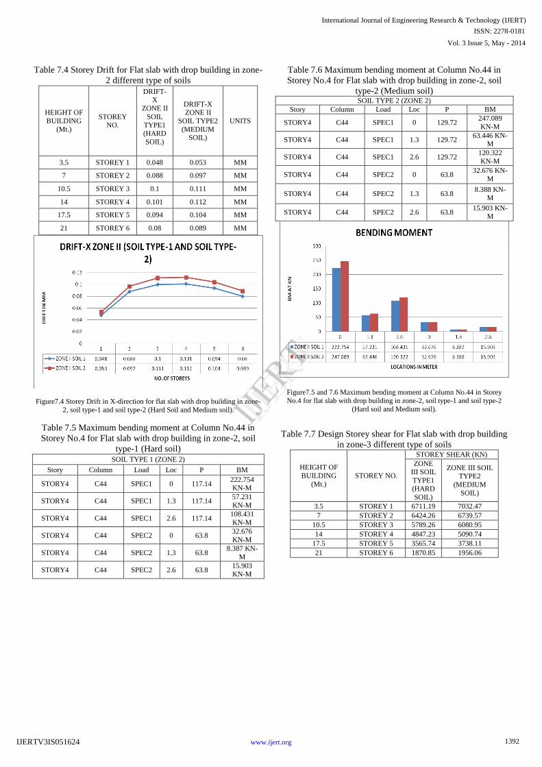
Table 7.4 Storey Drift for Flat slab with drop building in zone-
2 different type of soils
HEIGHT OF
BUILDING
(Mt.)
STOREY NO.
DRIFT-X
ZONE II
SOIL TYPE1
(HARD
SOIL)
DRIFT-X ZONE II
SOIL TYPE2
(MEDIUM SOIL)
UNITS
3.5 STOREY 1 0.048 0.053 MM
7 STOREY 2 0.088 0.097 MM
10.5 STOREY 3 0.1 0.111 MM
14 STOREY 4 0.101 0.112 MM
17.5 STOREY 5 0.094 0.104 MM
21 STOREY 6 0.08 0.089 MM
Figure7.4 Storey Drift in X-direction for flat slab with drop building in zone-
2, soil type-1 and soil type-2 (Hard Soil and Medium soil).
Table 7.5 Maximum bending moment at Column No.44 in
Storey No.4 for Flat slab with drop building in zone-2, soil
type-1 (Hard soil) SOIL TYPE 1 (ZONE 2)
Story Column Load Loc P BM
STORY4 C44 SPEC1 0 117.14 222.754
KN-M
STORY4 C44 SPEC1 1.3 117.14 57.231
KN-M
STORY4 C44 SPEC1 2.6 117.14 108.431
KN-M
STORY4 C44 SPEC2 0 63.8 32.676
KN-M
STORY4 C44 SPEC2 1.3 63.8 8.387 KN-
M
STORY4 C44 SPEC2 2.6 63.8 15.903 KN-M
Table 7.6 Maximum bending moment at Column No.44 in
Storey No.4 for Flat slab with drop building in zone-2, soil
type-2 (Medium soil) SOIL TYPE 2 (ZONE 2)
Story Column Load Loc P BM
STORY4 C44 SPEC1 0 129.72 247.089
KN-M
STORY4 C44 SPEC1 1.3 129.72 63.446 KN-
M
STORY4 C44 SPEC1 2.6 129.72 120.322
KN-M
STORY4 C44 SPEC2 0 63.8 32.676 KN-
M
STORY4 C44 SPEC2 1.3 63.8 8.388 KN-
M
STORY4 C44 SPEC2 2.6 63.8 15.903 KN-
M
Figure7.5 and 7.6 Maximum bending moment at Column No.44 in Storey
No.4 for flat slab with drop building in zone-2, soil type-1 and soil type-2
(Hard soil and Medium soil).
Table 7.7 Design Storey shear for Flat slab with drop building
in zone-3 different type of soils
HEIGHT OF
BUILDING
(Mt.)
STOREY NO.
STOREY SHEAR (KN)
ZONE
III SOIL
TYPE1 (HARD
SOIL)
ZONE III SOIL TYPE2
(MEDIUM
SOIL)
3.5 STOREY 1 6711.19 7032.47
7 STOREY 2 6424.26 6739.57
10.5 STOREY 3 5789.26 6080.95
14 STOREY 4 4847.23 5090.74
17.5 STOREY 5 3565.74 3738.11
21 STOREY 6 1870.85 1956.06
1392
International Journal of Engineering Research & Technology (IJERT)
IJERT
IJERT
ISSN: 2278-0181
www.ijert.orgIJERTV3IS051624
Vol. 3 Issue 5, May - 2014
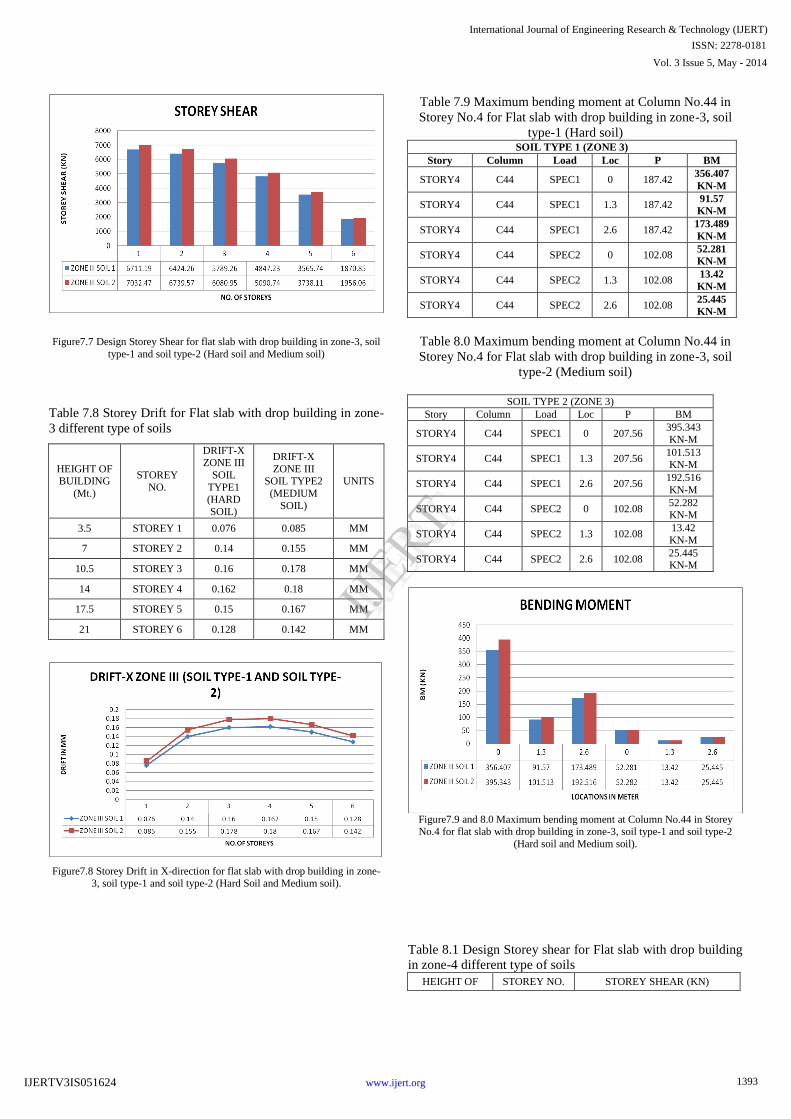
Figure7.7 Design Storey Shear for flat slab with drop building in zone-3, soil
type-1 and soil type-2 (Hard soil and Medium soil)
Table 7.8 Storey Drift for Flat slab with drop building in zone-
3 different type of soils
HEIGHT OF BUILDING
(Mt.)
STOREY
NO.
DRIFT-X ZONE III
SOIL
TYPE1 (HARD
SOIL)
DRIFT-X
ZONE III SOIL TYPE2
(MEDIUM
SOIL)
UNITS
3.5 STOREY 1 0.076 0.085 MM
7 STOREY 2 0.14 0.155 MM
10.5 STOREY 3 0.16 0.178 MM
14 STOREY 4 0.162 0.18 MM
17.5 STOREY 5 0.15 0.167 MM
21 STOREY 6 0.128 0.142 MM
Figure7.8 Storey Drift in X-direction for flat slab with drop building in zone-3, soil type-1 and soil type-2 (Hard Soil and Medium soil).
Table 7.9 Maximum bending moment at Column No.44 in
Storey No.4 for Flat slab with drop building in zone-3, soil
type-1 (Hard soil) SOIL TYPE 1 (ZONE 3)
Story Column Load Loc P BM
STORY4 C44 SPEC1 0 187.42 356.407
KN-M
STORY4 C44 SPEC1 1.3 187.42 91.57
KN-M
STORY4 C44 SPEC1 2.6 187.42 173.489
KN-M
STORY4 C44 SPEC2 0 102.08 52.281
KN-M
STORY4 C44 SPEC2 1.3 102.08 13.42
KN-M
STORY4 C44 SPEC2 2.6 102.08 25.445
KN-M
Table 8.0 Maximum bending moment at Column No.44 in
Storey No.4 for Flat slab with drop building in zone-3, soil
type-2 (Medium soil)
SOIL TYPE 2 (ZONE 3)
Story Column Load Loc P BM
STORY4 C44 SPEC1 0 207.56 395.343
KN-M
STORY4 C44 SPEC1 1.3 207.56 101.513 KN-M
STORY4 C44 SPEC1 2.6 207.56 192.516
KN-M
STORY4 C44 SPEC2 0 102.08 52.282 KN-M
STORY4 C44 SPEC2 1.3 102.08 13.42
KN-M
STORY4 C44 SPEC2 2.6 102.08 25.445 KN-M
Figure7.9 and 8.0 Maximum bending moment at Column No.44 in Storey No.4 for flat slab with drop building in zone-3, soil type-1 and soil type-2
(Hard soil and Medium soil).
Table 8.1 Design Storey shear for Flat slab with drop building
in zone-4 different type of soils
HEIGHT OF STOREY NO. STOREY SHEAR (KN)
1393
International Journal of Engineering Research & Technology (IJERT)
IJERT
IJERT
ISSN: 2278-0181
www.ijert.orgIJERTV3IS051624
Vol. 3 Issue 5, May - 2014
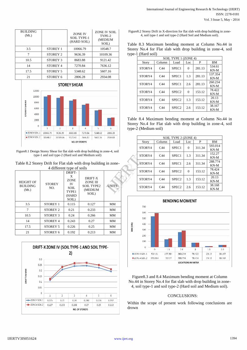
BUILDING
(Mt.) ZONE IV
SOIL TYPE-1 (HARD SOIL)
ZONE IV SOIL
TYPE-2
(MEDIUM
SOIL)
3.5 STOREY 1 10066.79 10548.7
7 STOREY 2 9636.39 10109.36
10.5 STOREY 3 8683.88 9121.42
14 STOREY 4 7270.84 7636.12
17.5 STOREY 5 5348.62 5607.16
21 STOREY 6 2806.28 2934.08
Figure8.1 Design Storey Shear for flat slab with drop building in zone-4, soil
type-1 and soil type-2 (Hard soil and Medium soil)
Table 8.2 Storey Drift for Flat slab with drop building in zone-
4 different type of soils
HEIGHT OF
BUILDING
(Mt.)
STOREY NO.
DRIFT-
X
ZONE
IV SOIL
TYPE1
(HARD SOIL)
DRIFT-X ZONE III
SOIL TYPE2
(MEDIUM SOIL)
UNITS
3.5 STOREY 1 0.115 0.127 MM
7 STOREY 2 0.21 0.233 MM
10.5 STOREY 3 0.24 0.266 MM
14 STOREY 4 0.243 0.27 MM
17.5 STOREY 5 0.226 0.25 MM
21 STOREY 6 0.192 0.213 MM
Figure8.2 Storey Drift in X-direction for flat slab with drop building in zone-
4, soil type-1 and soil type-2 (Hard Soil and Medium soil).
Table 8.3 Maximum bending moment at Column No.44 in
Storey No.4 for Flat slab with drop building in zone-4, soil
type-1 (Hard soil) SOIL TYPE 1 (ZONE 4)
Story Column Load Loc P BM
STORY4 C44 SPEC1 0 281.13 534.61
KN-M
STORY4 C44 SPEC1 1.3 281.13 137.354
KN-M
STORY4 C44 SPEC1 2.6 281.13 260.234
KN-M
STORY4 C44 SPEC2 0 153.12 78.422
KN-M
STORY4 C44 SPEC2 1.3 153.12 20.13
KN-M
STORY4 C44 SPEC2 2.6 153.12 38.167
KN-M
Table 8.4 Maximum bending moment at Column No.44 in
Storey No.4 for Flat slab with drop building in zone-4, soil
type-2 (Medium soil)
SOIL TYPE 2 (ZONE 4)
Story Column Load Loc P BM
STORY4 C44 SPEC1 0 311.34 593.014
KN-M
STORY4 C44 SPEC1 1.3 311.34 152.27 KN-M
STORY4 C44 SPEC1 2.6 311.34 288.774
KN-M
STORY4 C44 SPEC2 0 153.12 78.424 KN-M
STORY4 C44 SPEC2 1.3 153.12 20.13
KN-M
STORY4 C44 SPEC2 2.6 153.12 38.168 KN-M
Figure8.3 and 8.4 Maximum bending moment at Column
No.44 in Storey No.4 for flat slab with drop building in zone-
4, soil type-1 and soil type-2 (Hard soil and Medium soil).
CONCLUSIONS:
Within the scope of present work following conclusions are
drown
1394
International Journal of Engineering Research & Technology (IJERT)
IJERT
IJERT
ISSN: 2278-0181
www.ijert.orgIJERTV3IS051624
Vol. 3 Issue 5, May - 2014
1. For all the cases considered drift values follow a
parabolic path along storey height with maximum
value laying the fourth storey.
2. Use of flat slab with drop and without drop results in
drift value is marginally in a range of 0.5mm to 3mm.
still all drift values are within permissible limits, even
with shear walls.
3. The fundamental natural period value is much higher
in flat slab with drop buildings compared to flat slab
without drop building.
4. For all the structure, design base shear increases as
the number of stories increases. This increases design
base shear is gradual up to 6th
storey. The design base
shear of soil type-1 is less than the soil type-2 for all
type of zones.
5. The design base shear of zone-4 is higher compare to
other zones (i.e., zone-3 and zone-2) for all type of
structures.
6. In flat slab without drop building the maximum
bending moment at column no.45 in storey no.4 for all
type of soils and zone. In such that the flat slab with
drop building the maximum bending moment at
column no.44 in storey no.4 for all type of soils and
zones.
REFERENCES:
1. Sandesh D. Bothara, Dr.Valsson Varghese,” “Dynamic Analysis
Of Special Moment Resisting Frame Building With Flat Slab And Grid Slab” ISSN: 2248-9622, Vol. 2, Issue 4, July-August 2012,
pp.275-280.
2. P.M.B.Raj kiran nanduri, B.Suresh, S K. Nagaraju, M D00. Ihtesham hussain,” Critical comparison of flat plate multistoried
frames with and without R.C in filled walls under wind and
earthquake loads”, An International Journal (ESTIJ), ISSN: 2250-3498,Vol.3, No.2, April 2013.
3. Fayazuddin Ahmed Syed, B. Dean Kumar, Y. Chandrasekhar,
B.L.P. Swami,” Comparative Analysis of Flat Plate Multistoried Frames With and Without Shear Walls under
Wind Loads, ISSN: 2249 – 8958, Volume-2, Issue-1, October
2012. 4. Prof. K S Sable, Er. V A Ghodechor, Prof. S B Kandekar,”
Comparative Study of Seismic Behavior of Multistory Flat Slab
and Conventional Reinforced Concrete Framed Structures, (IJCTEE) Volume 2, Issue 3, June 2012.
5. Amit A. Sathawane & R.S. Deotale,” Analysis And Design of Flat
Slab And Grid Slab And Their Cost Comparison,International
journal of advanced technology in civil engineering,ISSN:2231-
5721,Volume-1,Issue-2,2012
6. Durrani A. J.; Mau S. T., AbouHashish A. A., and Yi Li, “Earthquake Response of Flat-Slab Buildings,” Journal of
Structural Engineering, Vol. 120, No. 3, March, 1994.
7. M. H. Haraj, K. A. Soudki, and T. Kuds, “Strengthening of Interior Slab-Column Connections Using a Combination of FRP Sheets
and Steel Bolts.” Journal of Composites for Construction, Vol. 10, No.5, October 1, 2006.
8. M. Altug Erberik and Amr S. Elnashai “Loss Estimation Analysis
of Flat-Slab Structures.” Natural Hazards Review, Vol. 7, No. 1, February 1, 2006
9. Dr. Uttamasha Gupta1, Shruti Ratnaparkhe, Padma Gome,”
Seismic Behaviour of Buildings Having Flat Slabs with Drops”, ISSN 2250-2459, Volume 2, Issue 10, October 2012.
1395
International Journal of Engineering Research & Technology (IJERT)
IJERT
IJERT
ISSN: 2278-0181
www.ijert.orgIJERTV3IS051624
Vol. 3 Issue 5, May - 2014