beetle /ipos plus - posnet€¦ · beetle /ipos plus user manual 7 care of the beetle /ipos plus...
TRANSCRIPT

BEETLE /iPOS plus All-in-one POS System
User Manual

We would like to know your opinion on this publication. Please send us a copy of this page if you have any constructive criticism. We would like to thank you in advance for your comments. With kind regards,
Wincor Nixdorf International GmbH Technical Documentation R&D SAT22 Wohlrabedamm 31 D-13629 Berlin E-Mail: [email protected] Order No.: 01750284105 A
Your opinion:

BEETLE /iPOS plus All-in-one POS System
User Manual
Edition March 2016
All brand and product names mentioned in this document are trademarks of their respective owners.
Copyright © Wincor Nixdorf International GmbH, 2016
The reproduction, transmission or use of this document or its contents is not permitted without express authority.
Offenders will be liable for damages. All rights, including rights created by patent grant or registration of a utility model or
design, are reserved. Delivery subject to availability; technical modifications possible.

Contents
About This Manual ......................................................................... 1
Introduction ................................................................................... 2
Manufacturer´s Certification .......................................................... 3 Europe-EU Declaration of Conformity ............................................. 3 FCC Radiation Exposure Statement ................................................. 5 FCC-Class A Declaration .................................................................. 5 BSMI (EMC for Taiwan) ................................................................... 6 Energy Efficiency ............................................................................. 6
Care of the BEETLE /iPOS plus ........................................................ 7
Recycling the BEETLE /iPOS plus ..................................................... 8
Warranty ........................................................................................ 9 Important Notes ............................................................................. 9 Safety Notes ................................................................................. 10
Overview ...................................................................................... 12 Front View with Stand ................................................................... 12 Back View with Stand .................................................................... 13
Important note for removal of back cover ................................. 14 AC Power Adapter ........................................................................ 15 Front Panel ................................................................................... 16
Initial setup .................................................................................. 17 Unpacking and Checking the Delivery Unit .................................... 17
Setting Up the Device ................................................................... 18 Ergonomic Terminal Workplace .................................................... 18
Basic settings................................................................................ 20 Components ................................................................................. 20
Processor types ........................................................................ 20 RAM ......................................................................................... 20 Hard Disk .................................................................................. 20 Display ..................................................................................... 20
Replacing the Lithium Battery ...................................................... 21
Projected Capacitive Touch Screen ............................................... 23 General Information ..................................................................... 23

Instructions for Using the Touch Screen ........................................ 23 Cleaning Instructions .................................................................... 24
Resistive Touch Screen ................................................................. 25 General Information ..................................................................... 25 Construction of the Resistive Touch Screen ................................... 25 Instructions for using the Touch Screen ........................................ 26 Cleaning Instructions .................................................................... 26
Replacement of the RAM module ................................................ 27
Installing the antenna (option)..................................................... 28
Installing the Wi-Fi flexible antenna (option) ............................... 32
Planning the installation .............................................................. 36 Dimensions ................................................................................... 36 Desktop version ............................................................................ 36 Wall mount version ...................................................................... 37 Required operation space ............................................................. 37 Installation site requirements ....................................................... 38
Desktop version ....................................................................... 38 Wall mount version .................................................................. 38
lnstalling to a stand ...................................................................... 39 Preparing the stand ...................................................................... 39 Preparing the display .................................................................... 40
Two-cable connection .............................................................. 40 Full cables connection .............................................................. 42
Installing the stand ....................................................................... 44
User Accessible I/O ...................................................................... 47 Connecting cables ......................................................................... 48 Disconnecting cables .................................................................... 49
Storage Media.............................................................................. 51 Replacement of the Hard Disk Drive .............................................. 51
Installing to a wall ........................................................................ 54 Preparation .................................................................................. 56
Connecting the display ............................................................. 56 Mounting height....................................................................... 57 Mounting location .................................................................... 58
Installation ................................................................................... 58 Fix wall mount back plate to the wall ........................................ 58

Fix wall mount front plate to the system ................................... 59 Secure the system to the wall ................................................... 60
iPOS plus Port Extender................................................................ 61
Starting Up the System ................................................................. 63
Operating the RFID/NFC reader.................................................... 64
Powering Down the System ......................................................... 65
Error reporting ............................................................................. 66
Technical Data .............................................................................. 67 AC Power Adapter ........................................................................ 69 iPOS plus Port Extender (for Desktop stand) .................................. 70 iPOS plus Port Extender (Standalone) ............................................ 70 Power Budgeting .......................................................................... 71
Appendix ...................................................................................... 73 Approved Printers List ................................................................... 73 Wi-Fi flexible antenna ................................................................... 74
Assembling the antenna to flap ................................................ 74 Assembling the Wi-Fi module to mini PCIe adapter ................... 74
Abbreviations ............................................................................... 75

BEETLE /iPOS plus User Manual 1
About This Manual
This documentation is intended to help you to work with the POS system and to serve as a reference work. The detailed table of contents help you find the desired information quickly and easily.
Notes in the manual are marked by this symbol. This symbol is used for warnings.
The type and scope of application programs depend on the customer’s own selection; therefore, software will not be discussed further in this manual.

2 BEETLE /iPOS plus User Manual
Introduction
The BEETLE /iPOS plus comes in two variants, one with the Projected Ca-pacitive and the other with Resistive touch.
Its key features are the bezel-free design with multi-touch capabilities and the elegantly designed aluminum back housing coupled with its support for the Celeron DC N3060 and the higher performance Pentium QC N3710 processors.

BEETLE /iPOS plus User Manual 3
Manufacturer´s Certification
The device complies with the requirements of the EEC directive 2004/108/EC with regard to ‘Electro-magnetic compatibility" and 2006/95/EC “Low Voltage Directive” and RoHS directive 2011/65/EU.
Therefore, you will find the CE mark on the device or packaging.
In addition, the BEETLE /iPOS plus has received the UL symbol and cUL symbol.
Europe-EU Declaration of Conformity
Hereby, Wincor Nixdorf declares that this device is in compliance with the essential requirements and other relevant provisions of Directive 1999/5/EC. Csěky [Czech]: Wincor Nixdorf tímto prohlašuje, že tento zařízení je ve
shodě se základními požadavky a dalšími příslušnými ustanoveními směrnice 1999/5/ES.
Dansk [Danish]: Undertegnede Wincor Nixdorf erklærer herved, at følgende udstyr Enhed overholder de væsentlige krav og øvrige relevante krav i direktiv 1999/5/EF.
Deutsch [German]: Hiermit erklärt Wincor Nixdorf, dass sich das Gerät in Übereinstimmung mit den grundlegenden Anforderungen und den übrigen einschlägigen Bestimmungen der Richtli-nie 1999/5/EG befindet.
Eesti [Estonian]: Käesolevaga kinnitab Wincor Nixdorf seadme vastavust direktiivi 1999/5/EÜ põhinõuetele ja nimetatud dire ktiivist tulenevatele teistele asjakohastele sätetele.
English: Hereby, Wincor Nixdorf declares that this device is in compliance with the essential requirements and other relevant provisions of Directive 1999/5/EC.
Español [Spanish]: Por medio de la presente declara que el dispositivo cumple con los requisitos esenciales y cualesquiera otras disposiciones aplicables o exigibles de la Directiva 1999/5/CE.
Ελληνική [Greek]: ΜΕ ΤΗΝ ΠΑΡΟΥΣΑ Wincor Nixdorf ΔΗΛΩΝΕΙ ΟΤΙ συσκευή ΣΥΜΜΟΡΦΩΝΕΤΑΙ ΠΡΟΣ ΤΙΣ ΟΥΣΙΩΔΕΙΣ ΑΠΑΙΤΗΣΕΙΣ ΚΑΙ ΤΙΣ ΛΟΙΠΕΣ ΣΧΕΤΙΚΕΣ ΔΙΑΤΑΞΕΙΣ ΤΗΣ ΟΔΗΓΙΑΣ 1999/5/ΕΚ.

4 BEETLE /iPOS plus User Manual
Français [French]: Par la présente Wincor Nixdorf déclare que l'appareil est conforme aux exigences essentielles et aux autres dispositions pertinentes de la directive 1999/5/CE.
Italiano [Italian]: Con la presente Wincor Nixdorf dichiara che questo dispositivo è conforme ai requisiti essenziali ed alle altre disposizioni pertinenti stabilite dalla direttiva 1999/5/CE.
Latviski [Latvian]: Ar šo Wioncor Nixdorf deklarē, ka ierīce atbilst Direktīvas 1999/5/EK būtiskajām prasībām un citiem ar to saistītajiem noteikumiem.
Lietuvių [Lithuanian]: Šiuo Wincor Nixdorf deklaruoja, kad šis prietaisas atitinka esminius reikalavimus ir kitas 1999/5/EB Direktyvos nu-ostatas.
Nederlands [Dutch]: Hierbij verklaart Wincor Nixdorf dat het toestel apparaat in overeenstemming is met de essentiële eisen en de andere relevante bepalingen van richtlijn 1999/5/EG.
Malti [Maltese]: Hawnhekk, Wincor Nixdorf jiddikjara li dan apparat jikkon-forma mal-ħtiġijiet essenzjali u ma provvedimenti oħrajn relevanti li hemm fid-Dirrettiva 1999/5/EC.
Magyar [Hungarian]: Alulírott, Wincor Nixdorf nyilatkozom, hogy a eszköz megfelel a vonatkozó alapvetõ követelményeknek és az 1999/5/EC irányelv egyéb elõírásainak.
Polski [Polish]: Niniejszym Wincor Nioxdorf oświadcza, że urządzenie jest zgodny z zasadniczymi wymogami oraz pozostałymi sto-sownymi postanowieniami Dyrektywy 1999/5/EC.
Português [Portu-guese]:
Wincor Nixdorf declara que este dispositivo está conforme com os requisitos essenciais e outras disposições da Directiva 1999/5/CE.
Slovensko [Slovenian]: Wincor Nixdorf izjavlja, da je ta Naprava v skladu z bistven-imi zahtevami in ostalimi relevantnimi določili direktive 1999/5/ES.
Slovensky [Slovak]: Wincor Nixdorf týmto vyhlasuje, že zariadenie spĺňa zá-kladné požiadavky a všetky príslušné ustanovenia Smer-nice 1999/5/ES.
Suomi [Finnish]: Wincor Nixdorf vakuuttaa täten että laite on direktiivin 1999/5/EY oleellisten vaatimusten ja sitä koskevien direk-tiivin muiden eh tojen mukainen.
Svenska [Swedish]: Härmed intygar Wincor Nixdorf att denna enhet står I överensstämmelse med de väsentliga egenskapskrav och övriga relevanta bestämmelser som framgår av direktiv 1999/5/EG.
Íslenska [Icelandic]: Hér með lýsir Wincor Nixdorf yfir því að tæki er í samræmi við grunnkröfur og aðrar kröfur, sem gerðar eru í tilskipun 1999/5/EC.
Norsk [Norwegian]: Wincor Nixdorf erklærer herved at utstyret enhet er i

BEETLE /iPOS plus User Manual 5
samsvar med de grunnleggende krav og øvrige relevante krav i direktiv 1999/5/EF.
The declaration of conformity may be consulted at http://www.wincor-nixdorf.com.
FCC Radiation Exposure Statement
This equipment complies with FCC radiation exposure limits set forth for an uncontrolled environment. This equipment should be installed and operat-ed with minimum distance 20 cm between the radiator and your body. This transmitter must not be co-located or operating in conjunction with any other antenna or transmitter. This device complies with Part 15 of the FCC Rules. Operation is subject to the following two conditions: 1. This device may not cause harmful interference, and 2. This device must accept any interference received, including interfer-
ence that may cause undesired operation.
FCC-Class A Declaration
This equipment has been tested and found to comply with the limits for a Class A digital device, pursuant to part 15 of the FCC Rules. These limits are designed to provide reasonable protection against harmful interference when the equipment is operated in a commercial environment. This equipment generates, uses, and can radiate radio frequency energy and, if not installed and used in accordance with the instruction manual, may cause harmful interference to radio communications. Operation of this equipment in a residential area is likely to cause harmful interference in which case the user will be required to correct the interference at his ex-pense. Modifications not authorized by the manufacturer may void user’s authority to operate this device. CAN ICES-3 (A)/NMB-3(A).

6 BEETLE /iPOS plus User Manual
BSMI (EMC for Taiwan)
Energy Efficiency
iPOS plus is tested in an accredited test lab and can meet the Eligibility Crite-ria for Integrated Desktop laid down in ENERGY STAR version 6.0 for Com-puters. On a request basis, an application can be made to Energy Star for listing.
The device complies with the requirements of the BSMI (Bureau of Standards, Metrology and Inspection, Minis-try of Economic Affairs) directive CNS13438 with regard to “Electromagnetic compatibility” with the limits for a Class B product.
BEETLE /iPOS plus User Manual 7
Care of the BEETLE /iPOS plus
Clean your system’s housing at regular intervals with a dry, lint-free cloth. If this does not suffice please use a suitable plastic-surface cleaner which you can order from Wincor Nixdorf International GmbH. For more information about cleaning read the chapter “Projective Capaci-tive Touch Screen” and “Resistive Touch Screen”. When cleaning always make sure that the power plug is disconnected and that no liquid finds its way into the device.

8 BEETLE /iPOS plus User Manual
Recycling the BEETLE /iPOS plus
Environmental protection does not begin when the time has come to dis-pose of the BEETLE; it begins with the manufacturer. This product was de-signed according to our internal norm “Environmental conscious product design and development”. The BEETLE /iPOS plus system is manufactured without the use of CFC and CHC and is produced mainly from reusable components and materials. Please do not stick labels onto plastic case parts. This would help us to re-use components and material. But there are still some parts that are not reusable. Wincor Nixdorf Inter-national GmbH guarantees the environmentally safe disposal of these parts in a Recycling Center, which is certified pursuant to ISO 9001 and ISO 14001. You can protect our environment by only switching on your equipment when it is actually needed. If possible, even avoid the stand-by-mode as this wastes energy, too. Also switch your equipment off when you take a longer break or finish your work. Please contact your competent branch or the Recycling Center Paderborn (for European countries) for information on how to return and reuse de-vices and disposable materials under the following mail address. Email: [email protected] or on the internet.

BEETLE /iPOS plus User Manual 9
Warranty
In general, damages due to
improper or insufficient maintenance,
improper use of the product or unauthorized modifications of the product,
inadequate location or surroundings Will not be covered by the warranty. For further information on the stipulation consult your contract. All parts of the product which are subject to wear and tear are not included in the warranty engagement. For detailed warranty arrangements please consult your contract documents.
Please order spare parts at the Wincor Nixdorf customer service.
Important Notes
The Wincor Nixdorf International GmbH is not responsible for any radio and television malfunctions which emerge from unauthorized changes in the device. Make sure that only cables and devices may be connected which are admitted by Wincor Nixdorf. The user is responsible for any malfunctions that emerge from the actions mentioned before.
The device may only be repaired by authorized qualified person-nel. Unauthorized opening of the device and inexpertly carried-out repairs may not only seriously jeopardize the safety of the user, but also cancel all warranty and liability agreements.
Expansion cards with electrostatically sensitive devices (ESD) may be marked with this sticker.

10 BEETLE /iPOS plus User Manual
When opening the device or handling modules fitted with ESD, please ob-serve the following instructions, which pertain to all electrostatic sensitive devices (ESDs):
Always use the antistatic kit.
Statically discharge yourself, for example by touching an earthed ob-ject (such as a heat radiator) before beginning to work with ESD-labeled components.
Likewise, all equipment and tools used in working with such compo-nents must be free of static charge.
Pull the mains plug before inserting or removing such components.
Only handle such components by their edges.
Never touch any terminal pins of the strip conductors on such compo-nents.
Safety Notes
The BEETLE /iPOS plus conforms to the current safety standards for data processing equipment.
If this device is taken from a cold environment into the operating room, moisture condensation may form. The device must be absolutely dry before being put into service; an acclimatization period of at least two hours must therefore be observed.
This device is equipped with a safety-tested power cable and may be connected only to a prescribed grounded-contact power socket.
When setting up the device, ensure that the power socket on the device and the grounded-contact power socket are easily accessible.
Whenever work of any kind is done on the device, as well as when data cables are plugged and/or unplugged, the device must be com-pletely disconnected from the line voltage. To do so, turn the device off and unplug the power cord.
To disconnect the device from the supply voltage completely, switch off the device and disconnect the power plug of the system.
Never plug in or unplug data communication lines during thunder-storms.

BEETLE /iPOS plus User Manual 11
Protect devices from vibrations, dust, moisture and heat.
Always dispose of used parts, such as batteries, in an environmentally safe manner.
In emergencies (e.g. damaged housing or damaged power cable, penetration by liquids or foreign bodies), the device must be switched off immediately, the power plug disconnected and the Customer Service of Wincor Nixdorf or your dealer must be notified.
Your BEETLE system is the result of modern technical innovation. So please see for according structural and technical surroundings to guar-antee a faultless and efficient work of your BEETLE. Therefore, you should connect your BEETLE or other IT-devices only to power supply systems with separately guided protective earth conductor (PE). This kind of electricity system is known as TN-S network. Do not use PEN conductors! Please also observe the recommendations of the norm DIN VDE 0100, Part 540, Appendix C2 as well as EN50174-2, §5.4.3.Thus you can help to avoid possible mal functions.
If you replace a storage medium, make sure that you only use the stor-age medium recommended or approved by Wincor Nixdorf.
You can connect or disconnect USB devices during operation of your BEETLE, provided that these devices comply with the specifications according to usb.org. Other peripheral devices (such as PoweredUSB printer) should be connected to or disconnected from your BEETLE system only after the BEETLE has been switched off.

12 BEETLE /iPOS plus User Manual
Overview
Front View with Stand
1 Display
2 Stand
3 Brightness adjustment LEDs
4 Power status indicator
5 On/off button

BEETLE /iPOS plus User Manual 13
Back View with Stand
1 Stand
2 Base cover of stand
3 *Back cover of stand
4 Frame cover of stand
5 Side-attach peripheral connection cover
6 RAM/mini-PCIe cover
7 Side-attach peripheral connection cover
8 Cable connection cover
*Observe the safety precaution mentioned on the next page when you remove the back cover of stand.

14 BEETLE /iPOS plus User Manual
Important note for removal of back cover
To avoid damage to the back cover of the stand, be careful of how you would remove it.
1. Insert a flat head screw driver into groove on the stand as shown and twist to open.
2. Do the same to the other side of the stand.
3. Remove stand back cover.

BEETLE /iPOS plus User Manual 15
AC Power Adapter
1 Power Connector
2 DC Power Out
3 Power LED
The external power supply is applicable for common line voltage. It automatically adjusts itself to the particular voltage (for grid input voltage and power supply see appendix).

16 BEETLE /iPOS plus User Manual
Front Panel
1. Brightness buttons
The touch buttons will be illuminated on first touch. Subsequent touches on the touch buttons increase or decrease the brightness level. 3 seconds after the last touch, the illumination of the touch button will be extin-guished and the setting is saved.
2. Activity indicator
Blinking green LED indicates hard disk or LAN activities depending on the settings in BIOS setup.
Blinking red LED conveys the error codes of the detected system faults. The error codes are displayed once only at boot up.
3. Power status indicator
OFF = AC main is switched off. Dimly lighted = Standby. Brightly lighted = Powered On. Blinking at 0.5Hz = Sleep or Hibernate
4. Power button
Single press will switch on/off. The duration depends on the BIOS setting.

BEETLE /iPOS plus User Manual 17
Initial setup
This chapter provides you with the information you need to prepare for the installation of the system.
Unpacking and Checking the Delivery Unit
Unpack the parts and check to see whether the delivery matches the
information on the delivery note. The delivery comprises the respec-
tive screen module. Data cables, necessary for operation, can be or-
dered separately. lf damage has occurred during shipping or if the
package contents do not match the delivery note, immediately inform
your Wincor Nixdorf sales outlet.
Transport the device only in its original packaging (to protect it
against impact and shock).

18 BEETLE /iPOS plus User Manual
Setting Up the Device
The BEETLE /iPOS plus is designed for in-house installation. It can be mounted on a stand for a desktop version, pole-mounted or wall-mounted. Set up the BEETLE /iPOS plus system where it will not be exposed to ex-treme environmental conditions. Protect the device from vibrations, dust, moisture, heat and strong magnetic fields.
Ergonomic Terminal Workplace
Please observe the following when setting up your terminal workplace:
Avoid direct glaring and reflective glaring. Use the screen only in a controlled luminance surrounding. Install the device with a viewing direction that is parallel to the windows.
Avoid reflective glaring caused by electric light sources.

BEETLE /iPOS plus User Manual 19
Permitted range of vision Position the screen within a preferred and permit ted range of vision, so that you can look onto the screen from above.
Preferred range of vision

20 BEETLE /iPOS plus User Manual
Basic settings
The BEETLE /iPOS plus is configured to your order. Additional peripheral devices are delivered separately, for example the swipe card reader. The modules must still be mounted to the system.
Components
The BEETLE /iPOS plus configuration can consist of the following components:
Processor types
Celeron Dual-core N3060 Pentium Quad-core N3710
RAM
2GB, 4GB or 8GB DDR3L SODIMM
Hard Disk
2.5” 7mm thick Hard Disk or SSD
Display
15" Color TFT LED backlight with touch options:
projected Capacitive touch, 10-pt touch multi-touch, or
5-wire Resistive Touch screen

BEETLE /iPOS plus User Manual 21
Replacing the Lithium Battery
Incorrect replacement of the Lithium Battery may lead to a risk of explo-sion. The end user must replace the lithium battery only by identical batteries or types recommended by Wincor Nixdorf. Do not throw Lithium Batteries into the trashcan. It must be disposed of in accordance with local regulations concerning special waste. Make sure that you insert the Battery the right way round by the indicated polarity in the picture below. Follow the following steps to replace the Lithium battery.
Always make sure that the system is switched off before you replace the battery.
! CAUTION
! WARNING

22 BEETLE /iPOS plus User Manual
Push the spring latch (1) and remove the Lithium Battery from its Socket
(2). Insert and press a new Lithium Battery of same type in the Socket. Make sure that you insert the battery the right way round, by the indicated polarity in the picture above.

BEETLE /iPOS plus User Manual 23
Projected Capacitive Touch Screen
General Information
The use of projected-capacitive touch screens has all the benefits a normal capacitive touch screen has:
fast processing of touch information
high sensitivity (use with hands, conductive pencils and also with thin gloves)
high resolution
improved legibility and display brightness due to optimal light trans-mission
Anti-glare-surface
In addition the technology of projected-capacitive touch screens is charac-terized by significant higher robustness and stability, because the active touch surface – different from common capacitive touch screens which were used until now - is located on the back side of the touch screen. Thus the active touch surface is not touched directly anymore and therefore will not wear off by normal use. As most of the surface contaminations do not cause an interference of the touch screen, this technology can be used in public or under severe environmental conditions.
Instructions for Using the Touch Screen
The touch screen responds to the lightest touches. The touch with only one finger is like the use of the left mouse button. The use of the touch screen with two fingers generates a zoom if the fingers are brought together or pulled apart. With a circular motion of the fingers the element on the dis-play can be rotated. This function must be supported by either the operating system or by the application.

24 BEETLE /iPOS plus User Manual
Cleaning Instructions
Always turn off the system before cleaning.
The glass surface of your Touch Screen should be cleaned with a mild, abrasive free, commercially available glass cleaning product. All pH neutral materials (pH 6 to 8) are good for cleaning. Cleaners with pH values 9 to 10 are not recommended. Cleaning with water and isopropyl alcohol is possible as well. Do not use solvents con-taining acetic acid. Use a soft, fine-meshed cloth to clean the surface. Dampen the cloth slightly and then clean the screen. A wrong maintenance may cause damages to the screen, which are not covered by warranty.

BEETLE /iPOS plus User Manual 25
Resistive Touch Screen
General Information
The resistive TFT Touch Screen is constructed by a hard-coated polyester top sheet that is overlaid on a conductively coated glass layer. Voltage is applied to the top sheet. As the user touches the screen, the top sheet compresses into contact with the glass layer, and current flows to the four corners in proportion to the distance from the edge. The controller then calculates the position of the finger or stylus, based on the current flow. Because the controller derives both the “X” and “Y” touch coordinates from the stable glass layer, the accuracy and operation of the touch screen is unaffected by damage to the top sheet caused by extended use or neglect.
Construction of the Resistive Touch Screen

26 BEETLE /iPOS plus User Manual
Instructions for using the Touch Screen
Touching the touch screen has the same effect as clicking the left mouse button. You only need to apply a little pressure with the fingertip. In this resistive process not only fingertip contact is recognized. The screen does react in any way if touched, for example, with a stylus. The recommended material for a stylus is polyacetal. The stylus should have a minimum spherical radius of 0.8 mm and contain no sharp edges or burrs that may cause damage to the top sheet.
Cleaning Instructions
Always turn off the system before cleaning
The surface of your Touch Screen should be cleaned with a water-based solvent or a non-abrasive cleaner. Do not use sol vents con-taining acetic acid or methylene chloride. Use a soft, fine-meshed cloth to clean the surface. Dampen the cloth slightly and then clean the screen. A wrong maintenance may cause damages to the screen, which are not covered by warranty.

BEETLE /iPOS plus User Manual 27
Replacement of the RAM module
First ensure that the device is switched off and that the power connector is disconnected.
1. Remove the screw of the
RAM cover and flip it open.
2. Release the catches of the RAM holder and pull out the RAM module.
3. Replace with new RAM mod-
ule and fix it back to the hold-er.
4. Repeat steps 1 and 2 in the reverse order. The replacement is complete.

28 BEETLE /iPOS plus User Manual
Installing the antenna (option)
This is an orderable kit from Wincor Nixdorf. Please contact your sales rep-resentative for details. The kit consists of:
An antenna module
A flap with antenna holes
Steps to install:
First ensure that the device is switched off and that the power connector is disconnected.

BEETLE /iPOS plus User Manual 29
1. Remove the right flap using a
screw driver.
2. Remove the RAM cover.
3. Unscrew the antenna
module to separate the
cover (1) from the antenna
(2).

30 BEETLE /iPOS plus User Manual
4. Push the screw end of the antenna (1) through the hole on the flap.
5. Route the antenna cable (1) through the cable channel on the inside of the back cover.
6. Connect the antenna cable to
the “Main” connector (2) on
the Wi-Fi module.

BEETLE /iPOS plus User Manual 31
7. Replace the flap (1) and screw in the antenna cover (2).
Replace the RAM cover (3). The installation is complete.

32 BEETLE /iPOS plus User Manual
Installing the Wi-Fi flexible antenna (option)
This is an orderable kit from Wincor Nixdorf. Please contact your sales rep-resentative for details. The kit consists of:
A Wi-Fi flexible antenna assembly.
A Wi-Fi module and mini PCIe adapter assembly.
Steps to install:
First ensure that the device is switched off and that the power connector is disconnected.

BEETLE /iPOS plus User Manual 33
1. Remove the right flap
using a screw driver.
2. Remove the RAM cover.
3. Attach the antenna to
the back of the flap, in
the location as shown.
For details of assembly,
please refer to Chapter
“Appendix: Wi-Fi flexi-
ble antenna”.

34 BEETLE /iPOS plus User Manual
4. Plug the Wi-Fi module and mini PCIe adapter assembly into the connector (1) and se-cure with the catch (2).
5. Route the antenna cable (1) through the cable channel on the inside of the back cover.
6. Connect the antenna cable to
the “Main” connector (1) on
the Wi-Fi module and mini
PCIe adapter assembly.

BEETLE /iPOS plus User Manual 35
7. Replace the flap.
Replace the RAM cover. The installation is complete.

36 BEETLE /iPOS plus User Manual
Planning the installation
This chapter provides you with the information you need to prepare for the installation of the system.
Dimensions
Please refer to the drawings below for dimensions of the desktop and wall mount versions. All dimensions are specified in millimeters. The views of the systems are not drawn to scale.
Desktop version

BEETLE /iPOS plus User Manual 37
Wall mount version
Required operation space
Maintain at least 50 mm from the side of the system to ensure proper ventilation during the operation of the system.
50 mm 50 mm
Wall
BEETLE/iPOS Plus BraswellSystem

38 BEETLE /iPOS plus User Manual
Installation site requirements
Desktop version
When selecting the installation site, ensure that:
The area is flat leveled.
The system to be installed on a table surface and not on a floor.
Wall mount version
To reduce the risk that someone may accidentally walk into the system, location such as walkway areas, hallways areas or crowded areas are not recommended.
Make sure that all applicable building and electric codes and accessibil-ity requirements are followed.
The mounting area must have adequate viewing area and ventilation, as well as access to an AC power outlet.
The mounting method must be able to support the combined weight of the system and the suspended weight of all cables attached to the system.
The system must be mounted to a solid concrete or brick wall with flat smooth surface.

BEETLE /iPOS plus User Manual 39
lnstalling to a stand
Take the stand and the monitor out of the packaging. For installation you
will need a Torx screwdriver to loosen and tighten the screws!
Preparing the stand
From the stand:
1. Remove the base cover.
2. *Remove the back cover.
3. Remove the frame cover.
* Observe the safety precaution mentioned on page 14 when you remove the back cover of the stand.

40 BEETLE /iPOS plus User Manual
Preparing the display
Two-cable connection
1. Place a piece of protec-
tion sheet on a flat sur-
face e.g. a table.
2. Lay the display face
down on the protection
sheet.
3. Tighten the four screws
half way through.
4. Remove the cable con-
nection cover at the bot-
tom of the display.
5. Connect cables.
The types of cables to connect depend on requirements. Please refer to section “Full cables connection“below for instructions to prepare a fully connected display.

BEETLE /iPOS plus User Manual 41
6. Pull the cables through
the cable support.
7. Secure them with the
cable clamps.
8. Fit the flanges (1) and (2)
on the cable connection
cover to the two holes
(3) and (4) as indicated
by the arrows.
9. Slide in the cable con-
nection cover.

42 BEETLE /iPOS plus User Manual
Full cables connection
1. Place a piece of protection
sheet on a flat surface e.g. a
table.
2. Lay the display face down on
the protection sheet.
3. Tighten the four screws half
way through.
4. Remove the cable connection
cover at the bottom of the
display.
5. Connect cables.
Please ensure that all cables are connected snugly into the space.
Pay attention to how the power connector (1) and ferrite core (2) should be routed.

BEETLE /iPOS plus User Manual 43
6. Fit the flanges (1) and (2)
on the cable connection
cover to the two holes
(3) and (4) as indicated
by the arrows.
7. Slide in the cable con-
nection cover.
44 BEETLE /iPOS plus User Manual
Installing the stand
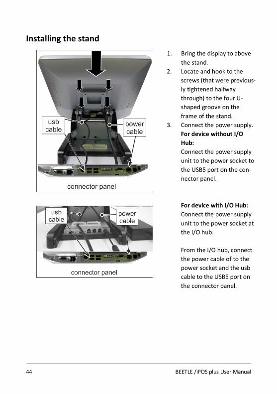
1. Bring the display to above
the stand.
2. Locate and hook to the
screws (that were previous-
ly tightened halfway
through) to the four U-
shaped groove on the
frame of the stand.
3. Connect the power supply.
For device without I/O
Hub:
Connect the power supply
unit to the power socket to
the USB5 port on the con-
nector panel.
For device with I/O Hub:
Connect the power supply
unit to the power socket at
the I/O hub.
From the I/O hub, connect
the power cable of to the
power socket and the usb
cable to the USB5 port on
the connector panel.

BEETLE /iPOS plus User Manual 45
4. Tighten the four Torx screws to secure the display to the stand.
5. Place in the frame cover.
6. Place in the back cover,
routing the cables through
the bottom.

46 BEETLE /iPOS plus User Manual
7. Place in the base cover. The
installation is complete.
To uninstall, follow the steps in the reverse order.
When uninstalling the stand always make sure that all cables are disconnected.
Never connect data cables when the system is switched on.

BEETLE /iPOS plus User Manual 47
User Accessible I/O
The following sockets are located under the cable connection cover of the display:
1 Cash drawer port (RJ12)
2 24V Power Input
3 Powered COM (COM2, DB9 female)
4 PLINK2/DVI-D
5 2 x USB 2.0 (USB4 and USB5)
6 2 x USB 3.0 (USB2 and USB3)
7 LAN (RJ45)
8 12V Powered USB
9 Standard COM (COM1, DB9 male)
10 Mass storage (HDD/SSD)
Make sure that all additional devices have a CE certificate.

48 BEETLE /iPOS plus User Manual
Connecting cables
All devices belonging to the modular BEETLE/iPOS plus that have a sepa-rate power cable must be connected to the same electric circuit. Connect the system as described below.
1. Tilt the system to the back.
2. Pull down the cable con-
nection cover to uncover
the connector panel.
3. Connect cables to their
assigned connectors.

BEETLE /iPOS plus User Manual 49
Disconnecting cables
Never unplug a cable by pulling on the cable; always take direct hold of the plug itself. Follow the procedure below when disconnecting cables:
Turn off all power and equipment switches.
Remove the cable cover.
Unplug all power plugs from the grounded-contact power sockets.
Unplug all data communication cables from the sockets of the data networks.
Unplug all cables from the devices.
With MINI-DIN plugs (Wincor Nixdorf
keyboards), the plug remains inserted until released.
Pull the plastic covering from the connecting socket with your thumb. The lock is released. The metal of the plug is visible.
To release a RJ12 plug push the latch under the plug to the top.
You loosen the USB-A- connector by pushing the covering of the connector.

50 BEETLE /iPOS plus User Manual
The P- USB connector is disengaged by pressing the spring that is marked by an arrow.
Manually loosen the knurled screws of the COM or DVI interface connector.
To release a RJ45 plug push down the latch (see arrow).

BEETLE /iPOS plus User Manual 51
Storage Media
Following storage media are available
1x 2.5” format-factor docking drive bay for 7mm thick hard disk or
Solid State Disk (SSD)
A solid state disk drive is a data storage drive that uses memory elements in place of a rotating disk to store data. The SSD easily substitutes the hard disk and emulates a hard disk drive interface. The most SSDs are flash memory based.
Replacement of the Hard Disk Drive
First ensure that the device is switched off and that the power connector is disconnected.
1. Tilt the display to the back.

52 BEETLE /iPOS plus User Manual
2. Pull down the cable con-
nection cover to uncover
the connector panel.
3. The HDD or SDD is in the
drive carrier located on the
left.
4. Remove the screw that fix
the drive carrier to the
connector panel and pull
out the drive carrier.

BEETLE /iPOS plus User Manual 53
5. Release the catches on the
drive carrier and pull out
the hard disk.
Handle the hard disk with
care while removing or in-
stalling it. Do not touch the
exposed electronics.
6. Replace the new hard disk
and fix it back to the drive
carrier.
7. Insert the disk carrier into
the connector panel.
Fix it with the screw, re-
moved previously.
The replacement is com-
plete.

54 BEETLE /iPOS plus User Manual
Installing to a wall
Unpack the parts from the wall mount kit and check whether the delivery matches the details of the delivery note.
You will need:
From the kit:
Wall mount back plate
Quantity: 1 piece
Wall mount front plate
Quantity: 1 piece
M4x8 Torx screws Quantity: 4 pieces

BEETLE /iPOS plus User Manual 55
For installation you will need the following (not supplied):
- a drill set
- a Torx screwdriver
- a marker
- 4 pieces of fasteners*
*Fastener types
Fasteners are not included in the wall mount kit. The recommended fas-
tener types to wall mount the system are:
Fischer universal plug (UX 6 x 50) (http://www.fischer.de)
Recommended Screw for wall is Pan head self-tapping M5 x 55.
Drill Diameter: 6 mm
Min Hole Depth: 60 mm
Load per anchor for concrete: 60 kg (Safety factor accounted for)
Load per anchor for Solid brick: 30 kg (Safety factor accounted for)
Thorsman wall plug (TP 6 x 30) (http://www.thorsman.com)
Recommended Screw for wall is Pan head Wood Screw TGS-C3- 4.8 x 38L
Drill Diameter: 6 mm
Min Hole Depth: 40 mm
Load per anchor for concrete: 40 kg
Load per anchor for Solid brick: 30 kg
Safety factor: 6
Fasteners Quantity: 4 pieces

56 BEETLE /iPOS plus User Manual
Preparation
Connecting the display
1. Place a piece of protection
sheet on a flat surface e.g.
a table.
2. Lay the display face down
on the protection sheet.
3. Tighten the four screws
half way through.
4. Remove the cable connec-
tion cover at the bottom
of the display.
5. Connect cables.
The types of cables to connect depend on requirements. The illustration above shows a case where only two types of cables are connected.

BEETLE /iPOS plus User Manual 57
6. Slide in the cable connection
cover and pull the cables
through the opening at the
bottom.
Mounting height
The mounting height of the system should be appropriate and comfortable for the majority of users. Based on the recommendation of the ADA (American Disability Associa-tion), it is recommended that the highest point of the display should not exceed 1370mm height. It is also recommended that the system is approximately 122 cm (48 in) from the floor to the center of the display when the user is in the standing position.

58 BEETLE /iPOS plus User Manual
Mounting location
Once you have determine the mounting height, with the help of the wall mount back plate, mark the location of the four holes on the wall.
Installation
The wall mount plate must be installed by a professional and quali-fied installer who is familiar with the building construction methods and the electrical code that are govern by the local laws on the public access areas. Use only Wincor Nixdorf wall mount plate.
Fix wall mount back plate to the wall
Prepare the mounting points penetrating from the wall according to the dimension of the mounting holes on the back of the system.
When the system is mounted onto the wall, ensure that the wall mount back plate must be attached permanently and securely to pre-vent the system from falling and damaged. Failing to do so may also cause injury to others.
Use the recommended fasteners (not supplied) to attach the wall mount back plate onto the concrete wall.

BEETLE /iPOS plus User Manual 59
Check and ensure that the wall mount back plate is mounted squarely by using a bubble level.
After installation, ensure that the screw heads are flushed or below the outer surface of the wall mount back plate.
Ensure that the wall mount back plate is firmly and securely attached to the wall.
Fix wall mount front plate to the system
Align the 4 mounting holes of the wall mount front plate onto the mounting holes at the back of the display.

60 BEETLE /iPOS plus User Manual
Secure the wall mount front plate onto the display using the screws provided in the wall mount kit.
Secure the system to the wall
Ensure that the power cable has been connected onto the system.
Hook the system with its wall mount front plate installed, onto the wall mount back plate that has been mounted on the wall. Ensure that the hooks at both sides of the wall mount back plate are securely locked on the slots of the wall mount front plate.
Tighten the thumb screw on the top of the wall mount front plate to secure the hooks of the wall mount plates.
Dress the cables routing according to the store set up or the overall in-stallation site plan
Hooks
Thumb screw

BEETLE /iPOS plus User Manual 61
iPOS plus Port Extender
The I/O Port Extender is an accessory designed exclusively for iPOS plus family of all-in-one POS terminals; to extend the I/O ports to add POS-specific I/O ports, namely two powered COM power, one 24V powered USB and two 12V powered USB. It mounts on the base of the desktop stand for the iPOS Advanced. The Port Extender is powered by a 24V power supply, and the iPOS plus Advanced in turn receives power from the DC24 OUT port. It also has a port for supplying power to a 2.5” hard disk or SSD for a RAID configuration. The powers available at the I/O ports are controlled by the iPOS plus Advanced such that when the system enter sleep or powered down state the powers are cut off thereby conserving power.
Power input DC24V IN 24V DC (connect to 24V power supply
User interface COM5 Rated voltage: 12V, 5V
COM6 Rated current: 1A combined (each supply)
PSUB12V 2x powered USB, rated 3A
PSUB24V 1x powered USB, rated 3A
Power output DC24V Out 24V DC (connect to iPOS plus Advanced)
USB Upstream USB Type B (connect to iPOS plus Advanced)
2nd
HDD Power For optional second hard disk

62 BEETLE /iPOS plus User Manual

BEETLE /iPOS plus User Manual 63
Starting Up the System
Install the BEETLE /iPOS plus and switch on the system with the Power but-ton located on the left side of the lower right corner of the unit. The sys-tem will start booting up displaying a BIOS boot up screen . The following message is shown for a brief duration during which you may press <F2> to enter setup. WN STD xx/xx dd/mm/yyyy
Press <F2> to enter setup
“xx/xx” is the placeholder of the BIOS version number and “dd/mm/yyyy” is the date of release. Following the BIOS boot-up the operating system will boot up if a bootable storage device is present. The default boot priorities is as shown below, to change the order of boot priority please navigate to the Boot tab of the BIOS setup menu.
USB Key
USB CD/DVD
USB Hard Disk
Hard Disk
Network
64 BEETLE /iPOS plus User Manual
Operating the RFID/NFC reader
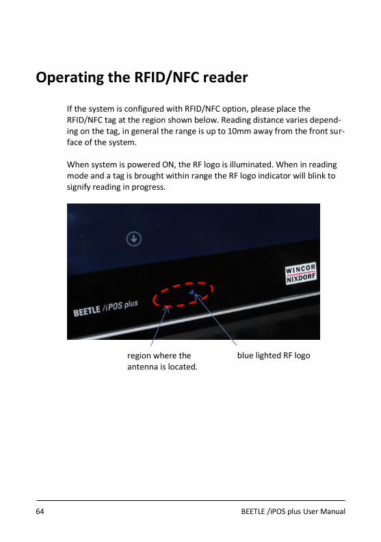
If the system is configured with RFID/NFC option, please place the RFID/NFC tag at the region shown below. Reading distance varies depend-ing on the tag, in general the range is up to 10mm away from the front sur-face of the system. When system is powered ON, the RF logo is illuminated. When in reading mode and a tag is brought within range the RF logo indicator will blink to signify reading in progress.
region where the antenna is located.
blue lighted RF logo

BEETLE /iPOS plus User Manual 65
Powering Down the System
Always perform an orderly shutdown from the operating system otherwise there is a risk of corruption. If system become unresponsive due to applica-tion freeze up, press and hold the power button (about 6 seconds) until the system shutdown. In case you switch off the AC main, wait at least 5 seconds before switching it on again to allow the residual charge to drain completely otherwise the system might not respond to the power button.

66 BEETLE /iPOS plus User Manual
Error reporting
When an error condition is detected, it is reported by a repetitive train of blinking red LED. Decode by counting the number of blinks in a train and check against the error code table below.
Number of pulses Error description
1 Not used
2 Not used
3 Not used
4 Not used
5 Capacitive Sense board is faulty
6 Ambient Light/Proximity Sensor faulty

BEETLE /iPOS plus User Manual 67
Technical Data
Processors Supported Celeron DC N3060 2.48GHz
Pentium QC N3710 2.56GHz
Memory Single-slot SODIMM
Supports 2GB, 4GB & 8GB DDR3L 1600
Primary Display 15“ TFT, 1024x768
LED backlight, 320 cd/m2 (typical)
Touch Options Projected Capacitive, 10-point multi-touch
5-wire Resistive
Audio Integrated stereo speaker, 2x2W
Mass storage
2.5“ SATA Hard disk or SSD,
slim-type (7 mm)
Expansion Slots 1x mini-PCI Express (half & full size)
M.2, 2280, B-key edge connector
Internal TPM Option Infineon SLB9665 TPM 2.0
Internal RFID/NFC Op-tion
Card standards supported:
ISO/IEC 18092
ISO/IEC 14443A/MIFARE
ISO/IEC 14443B
User Accessible I/O 1x Powered COM (COM1)
1x Standard COM (COM2)
2x USB 2.0
2x USB 3.0
1x 12V Powered USB
1x LAN
1x Cash drawer
1x PLINK2/DVI-D

68 BEETLE /iPOS plus User Manual
Peripheral Interfaces 1x USB (left)
1x USB (right)
Side-attached Peripheral options
Magnetic Swipe Card, ISO 3-track or JIS-2
WaiterLock (ID iButton)
RFID/NFC reader
Fingerprint Reader
Operating Systems sup-ported
Windows 7 Pro, POSReady 7,
Windows 8.1 Pro & Industry,
Windows 10
WNLPOS4 (Linux)
Middleware JavaPOS 1.13 / OPOS UDM
Mounting method & options
VESA100
Desktop stand or wall-mounted kit
Operating Environment 5 to 40o C
5 to 85% RH
IP Rating IP54 at the front surface
Certifications CE Class B, FCC Class A, UL, CCC, BSMI
Wi-Fi: R&TTE
Dimensions Refer to chapter “Planning the installation”
Weight
3 kg (without stand) 5 kg (with stand)

BEETLE /iPOS plus User Manual 69
AC Power Adapter
Only use power supply units (PSU) released or approved by Wincor Nix-dorf. The PSU has to comply with the following minimal requirements and common standards:
Rated input voltage 100-240VAC
Rated input current 2.0A
Input frequency range 47-63 Hz
Rated output voltage 24V ± 5%
Rated output current 5.0A
Max. output power 120W at ambient of 45 degree C,
100W at ambient of 55 degree C
Approvals and Certification UL Listed, TÜV-GS, CE
70 BEETLE /iPOS plus User Manual
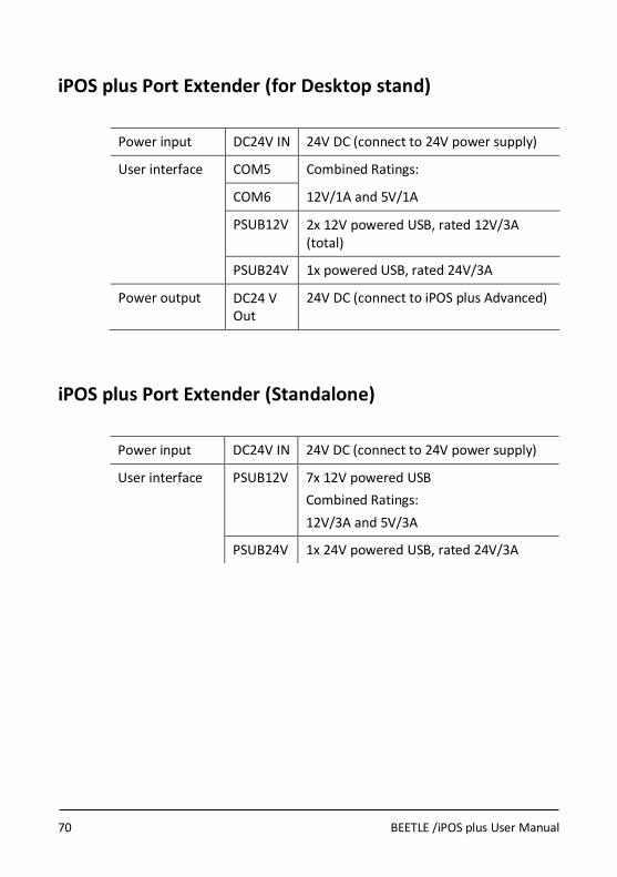
iPOS plus Port Extender (for Desktop stand)
Power input DC24V IN 24V DC (connect to 24V power supply)
User interface COM5 Combined Ratings:
COM6 12V/1A and 5V/1A
PSUB12V 2x 12V powered USB, rated 12V/3A (total)
PSUB24V 1x powered USB, rated 24V/3A
Power output DC24 V Out
24V DC (connect to iPOS plus Advanced)
iPOS plus Port Extender (Standalone)
Power input DC24V IN 24V DC (connect to 24V power supply)
User interface PSUB12V 7x 12V powered USB
Combined Ratings:
12V/3A and 5V/3A
PSUB24V 1x 24V powered USB, rated 24V/3A

BEETLE /iPOS plus User Manual 71
Power Budgeting
Take note that the total power available for the system is limited to 120W, the DC output rating of the external power supply. The table below shows the power budget which the system integrator must refer to in deciding what external devices that tap power can be connected to the system to en-sure the operation is not disrupted due to excessive load.
Port name Ratings Maximum continuous
power
Base Unit note 1 - - 30W 30W
User Accessible I/O USB1
USB2
5V/1A
40W
90W
USB4
USB5
5V/1A
USB3.7 5V/0.5A
12V/1.85A
PLINK2 12V/3.7A
5V/1A
COM1 5V/1A & 12V/1A
I/O Hub PUSB24V 24V/3A
50W PUSB12V
(2x or 7x)
12V/3A & 5V/3A
COM5
COM6
5V/1A & 12V/1A
Note 1: The Base Unit includes all internal modules and devices, and ex-
cludes external peripherals at the User Accessible I/O that draw power from the system’s I/O ports.
30W is budgeted for the Base Unit, what’s remaining is 90W to be shared among the available ports. It has to be noted that the rating of each port does not mean that’s the power available and all the ports can be loaded to

72 BEETLE /iPOS plus User Manual
their rated powers simultaneously. System integrator has to observe the 90W limit which total consumptions of all connected ports must not exceed.
The budgeted powers for the User Accessible I/O and the I/O Hub are prac-tical computation of actual powers drawn by POS peripherals. System inte-grators are not restricted to the stated budgeted powers but are free to al-locate according to their system configuration, limited by the 90W maxi-mum available continuous power.

BEETLE /iPOS plus User Manual 73
Appendix
Approved Printers List
The following are the approved printers that are allowed to be connected to the BEETLE /iPOS plus +24Vdc Powered USB port:
Model Manufacturer
TH180 series Wincor Nixdorf
TH230 series Wincor Nixdorf
TH320 series Wincor Nixdorf
TH420 series Wincor Nixdorf
ND77 series Wincor Nixdorf
ND210 series Wincor Nixdorf
ND220 series Wincor Nixdorf
TH200 series Wincor Nixdorf
TH250 series Wincor Nixdorf
Connecting printer that are not in the above approved list to the +24Vdc Powered USB port may cause safety hazard and endanger the user and the nearby people. Please consult Wincor Nixdorf if in doubt.
! WARNING

74 BEETLE /iPOS plus User Manual
Wi-Fi flexible antenna
Assembling the antenna to flap
Assembling information
Paste the flex-antenna of the Wi-Fi antenna assembly to the plastic side cover in the position as shown in the photo.
Distance of flex-antenna from the side cover rib is B = 11 ± 0.5 mm.
Bend and route the flex-antenna cable as shown in the photo. Keep a distance of A = 7 ±1 mm between the flex-antenna and its cable.
Use a piece of tape to secure the flex-antenna cable to the side cover as shown in the photo.
Assembling the Wi-Fi module to mini PCIe adapter
Assembling Information
Assemble the Wi-Fi module (1) to the mini PCIe adapter (2).
Tighten with the two screws provided (3) and (4).

BEETLE /iPOS plus User Manual 75
Abbreviations
CE European Symbol of Conformity
CFC Chlorofluorocarbon
CHC Chlorinated hydrocarbon
COMn* Powered RS 232 Interface (Asterisk denotes Power)
cUL Canadian Registration (Recognized by UL)
DIN Deutsches Institut für Normen (German Institute for Standards)
D-Sub D- Shaped Sub miniature
ESD Electronically Sensitive Devices
HDD Hard Disk Drive
IEC International Electrotechnical Commission
ISO International Organization for Standardization
LAN Local Area Network
LED Light Emitting Diode
PEN Protective Earth Neutral Conductor
RAM Random Access Memory
SSD Solid State Disk (flash medium)
TN-S Terre Neutre- Separé
UL Underwriters Laboratory (standards)
USB Universal Serial Bus
VGA Video Graphics Adapter
VESA Video Electronics Standards Association
WN Wincor Nixdorf International GmbH


Wincor Nixdorf Pte Ltd 151 Lorong Chuan New Tech Park #05-01A/B Singapore 556741 Order No.: 01750284105 A