beckman du 800 spectrophotometer installation and ... · pdf filedu® 800 spectrophotometer...
TRANSCRIPT

DU® 800 SpectrophotometerInstallation and
Operating Instructions512860AC
April 2002
Beckman Coulter, Inc.4300 N. Harbor Blvd., Fullerton, CA 92835
© 2002 Beckman Coulter, Inc., Printed in U.S.A.
TM


DU® 800 Spectrophotometer Installation & Operating Instructions
Table of Contents
Overview..................................................................................................................1
Standard Applications Software ..............................................................................2
Optional Applications Software...............................................................................2
Principles of Operation ............................................................................................4Optical Principle ................................................................................................4Blanking.............................................................................................................4Reading ..............................................................................................................5Scanning.............................................................................................................6Read Average Time............................................................................................6Smoothing..........................................................................................................6
Spectrophotometer ...................................................................................................7
Computer (PC) .........................................................................................................8
Software ...................................................................................................................8
Space Requirements.................................................................................................9
Power Requirements ..............................................................................................10
Unpacking Instrument............................................................................................11
Shipping Kit ...........................................................................................................12
PC, Monitor, and Optional Printer .........................................................................12
Hardware Installation.............................................................................................13
Software Installation ..............................................................................................15
General...................................................................................................................17
Taking Single Wavelength Readings .....................................................................18Editing a Method .............................................................................................19Blanking...........................................................................................................22Reading ............................................................................................................23Print, Save, and Clear.......................................................................................24
Taking a Wavelength Scan .....................................................................................25Editing a Method .............................................................................................26Blanking...........................................................................................................28Scanning...........................................................................................................28Print, Save, and Clear.......................................................................................30
Performing a Kinetic Run ......................................................................................30Editing a Method .............................................................................................31Blanking...........................................................................................................34
i

DU® 800 Spectrophotometer Installation & Operating Instructions
Reading ............................................................................................................35Print, Save, and Clear.......................................................................................38
General...................................................................................................................39Default Directories...........................................................................................39File Extensions.................................................................................................40Passwords.........................................................................................................40Logon Levels ...................................................................................................41
On-Line Launch (with System Initialization)........................................................41Off-Line Launch ..............................................................................................43
Common Front End ...............................................................................................43User Interface...................................................................................................43
Main Menu.............................................................................................................44
Toolbar and Icons...................................................................................................45BLANK, (GO) READ/SCAN, and STOP Buttons..........................................45RediRead and RediScan...................................................................................46Cell Match........................................................................................................46Edit Method .....................................................................................................46Open File, Save File, and Clear .......................................................................46Accessories ......................................................................................................48
Method Parameters Frame .....................................................................................48
Status & Control Frame .........................................................................................49Status Information............................................................................................49
User Status .................................................................................................49Blank Status ...............................................................................................49UV Lamp Status.........................................................................................49
Status & Control Elements ..............................................................................49Sources.......................................................................................................49Holders.......................................................................................................50
Applications Frame................................................................................................51
Permanent Status Bar.............................................................................................51Operation and Status Message.........................................................................51Spectrophotometer Status ................................................................................51
System Menu .........................................................................................................52User Logon / Change User...............................................................................52Change Password .............................................................................................52Log Off.............................................................................................................53Sources.............................................................................................................53Accessories ......................................................................................................53Exit...................................................................................................................54
ii

DU® 800 Spectrophotometer Installation & Operating Instructions
Transport/Holder....................................................................................................54
Sipper .....................................................................................................................55
Batch Sampler........................................................................................................56
Peltier Temperature Controller ..............................................................................59Manual Control ................................................................................................59Automatic Control ...........................................................................................59
Applications Menu.................................................................................................60Standard and Optional Applications ................................................................60Custom Applications........................................................................................61
Methods Menu .......................................................................................................61<Default Method>............................................................................................61Select Method ..................................................................................................61Create/Edit Method..........................................................................................62Delete Current Method ....................................................................................63Copy Methods from Other Users.....................................................................63Copy to Custom Applications..........................................................................63Backup/Export Methods ..................................................................................65Restore/Import Methods ..................................................................................65
Tools Menu ............................................................................................................67
RediRead................................................................................................................68
RediScan ................................................................................................................70Function Menu.................................................................................................72
Trace...........................................................................................................72Annotate.....................................................................................................72Zoom..........................................................................................................73Grid ............................................................................................................73
Axis Menu........................................................................................................74Set Scan Limits ..........................................................................................74Autoscale ...................................................................................................74Dynamic Autoscaling ................................................................................74Read/Display Mode ...................................................................................75
Cell Matching ........................................................................................................75
Data Export ............................................................................................................77
Electronic Signatures .............................................................................................7821 CFR Part 11.................................................................................................78View Electronic Signature(s) ...........................................................................78Add Electronic Signature.................................................................................79
User Options ..........................................................................................................80Output Tab .......................................................................................................81
iii

DU® 800 Spectrophotometer Installation & Operating Instructions
Header Tab .......................................................................................................81Graph Tab.........................................................................................................81Colors Tab........................................................................................................81
Administration .......................................................................................................81
System Options ......................................................................................................82Setup Tab .........................................................................................................82Output Tab .......................................................................................................84Headers Tab .....................................................................................................85Graph Tab.........................................................................................................86Colors Tab........................................................................................................87Regulatory Tab.................................................................................................88
User Account Manager ..........................................................................................90
Delete Custom Applications ..................................................................................91
View System Audit Trail........................................................................................92
Source Scheduler ...................................................................................................93
Performance Validation Scheduler.........................................................................94
Backup/Export System ..........................................................................................96
Restore/Import System ..........................................................................................96
Add Software Option(s).........................................................................................98
Create Backup License File ...................................................................................99
Diagnostic Menu..................................................................................................100System Status.................................................................................................100
User Diagnostics ..................................................................................................101Calibrate Wavelength.....................................................................................101Run Baseline Test ..........................................................................................102Set Scan Gains ...............................................................................................102Reset Source Hours........................................................................................104
Service Diagnostics..............................................................................................105Calibration Info..............................................................................................105Wavelength Drive Run...................................................................................106DRP Scan.......................................................................................................107Blocked Beam Noise .....................................................................................108Erase EEPROM .............................................................................................108
Help Menu ...........................................................................................................109
Applications Software..........................................................................................110
Transport ..............................................................................................................111
Cell Holders .........................................................................................................112
Sipper Accessory .................................................................................................113
iv

DU® 800 Spectrophotometer Installation & Operating Instructions
Sipper Controls ..............................................................................................113
Batch Sampler Accessory ....................................................................................115Beckman Coulter (ISCO) Batch Sampler ......................................................115
Automatic Operation................................................................................116Manual Operation ....................................................................................117
Peltier Temperature Controller ............................................................................117Standard Controller........................................................................................118High Performance Controller.........................................................................118
Storage and Transport ..........................................................................................121
Sample Compartment Configuration ...................................................................121
Performance Specifications .................................................................................122
Physical & Environmental Specifications............................................................122
General Information.............................................................................................123
System Status .......................................................................................................124
Fuse Replacement ................................................................................................124
UV Source Replacement......................................................................................126
Visible Source Replacement ................................................................................129Part I. Replacing the Source..........................................................................129Part II. Peaking the Source............................................................................132
Startup Diagnostic Tests ......................................................................................135
Operational Failures.............................................................................................136
Operational Messages ..........................................................................................137
Warranty Registration ..........................................................................................139
Beckman Coulter Offices.....................................................................................140North America ...............................................................................................140
United States ............................................................................................140Canada ...........................................................................................................140Latin America ................................................................................................140
Mexico .....................................................................................................140Europe............................................................................................................141
France.......................................................................................................141Germany...................................................................................................141Italy ..........................................................................................................141Netherlands ..............................................................................................141Spain ........................................................................................................142Sweden.....................................................................................................142Switzerland ..............................................................................................142Turkey ......................................................................................................142
v
DU® 800 Spectrophotometer Installation & Operating Instructions
United Kingdom ......................................................................................142Asia/Pacific ....................................................................................................143
Australia...................................................................................................143China........................................................................................................143Hong Kong...............................................................................................143Japan ........................................................................................................143Singapore .................................................................................................144Taiwan......................................................................................................144
Eastern Europe, Middle East, Africa .............................................................144South Africa...................................................................................................144
vi

DU® 800 Spectrophotometer Installation & Operating Instructions
List of Figures
Figure 1 DU 800 Spectrophotometer with Computer and Monitor ................................... 1Figure 2 Optical Diagram ................................................................................................... 4Figure 3 DU 800 Spectrophotometer ................................................................................. 7Figure 4 DU 800 System and Applications Software ........................................................ 8Figure 5 Minimum Space Requirements with Desktop PC ............................................... 9Figure 6 Minimum Space Requirements with Tower PC .................................................. 9Figure 7 Space Requirements with Optional Accessories and Tower PC ....................... 10Figure 8 DU 800 Spectrophotometer on Pallet ................................................................ 11Figure 9 DU 800 Spectrophotometer Rear Panel Connectors ......................................... 13Figure 10 USB Connections on the PC and Spectrophotometer ...................................... 14Figure 11 Found New Hardware Wizard Screen ............................................................. 16Figure 12 User Display Screen ........................................................................................ 17Figure 13 Window with Fixed Wavelength Application Selected ................................... 19Figure 14 Method Window for Fixed Wavelenght Before the Change ........................... 20Figure 15 Method Window for Fixed Wavelength After the Change ............................. 21Figure 16 Window with Fixed Wavelength Application and all Changes Made ............ 22Figure 17 Window with Fixed Wavelength Application and Measurement
Taken From Three Samples Using a Single Cell Holder ................................. 24Figure 18 Window with Wavelength Scan Application Selected .................................... 26Figure 19 Method Window for Wavelength Scan After the Change ............................... 27Figure 20 Method Parameters Frame After the Change .................................................. 28Figure 21 Window with Wavelength Scan Application and Scans
Taken From Three Samples Using a Single Cell Holder .................................. 29Figure 22 Window with Kinetics/Time Application Selected ......................................... 31Figure 23 Method Window for Kinetics/Time Before the Change .................................. 32Figure 24 Method Window for Kinetics After the Change .............................................. 33Figure 25 Window with Kinetics/Time Application and All Changes Made .................. 34Figure 26 Data Acquisition Mode .................................................................................... 36Figure 27 Rates Mode ...................................................................................................... 37Figure 28 DU 800 System Initialization Screen .............................................................. 42Figure 29 Integrated Frame-Oriented User Interface ....................................................... 44Figure 30 Applications Frame .......................................................................................... 51Figure 31 User Logon Screen .......................................................................................... 52Figure 32 Change Password for Administrator Screen .................................................... 53Figure 33 Accessories Screen with Transport/Holder Tab Selected ................................ 54Figure 34 Accessories Screen with Sipper Tab Selected ................................................. 55Figure 35 Accessories Screen with Batch Sampler Tab Selected .................................... 56Figure 36 Accessories Screen with Temp Controller Tab Selected ................................. 59Figure 37 Delete Current Method Screen ........................................................................ 63
vii

DU® 800 Spectrophotometer Installation & Operating Instructions
Figure 38 Copy Methods from Other User Screen ...........................................................63Figure 39 Copy Methods to Custom Applications Screen ...............................................64Figure 40 Backup/Export Methods Screen .......................................................................65Figure 41 Restore/Import Methods Screen .......................................................................66Figure 42 RediRead Screen ..............................................................................................69Figure 43 RediRead Dialog Screen ..................................................................................70Figure 44 RediScan Screen ...............................................................................................71Figure 45 Scan Without a Blank Dialog ...........................................................................72Figure 46 Set Scan Limits Screen .....................................................................................74Figure 47 Cell Matching Screen .......................................................................................75Figure 48 Example of Data Exported as a CSV File ........................................................77Figure 49 Electronic Signature Authentication Screen .....................................................79Figure 50 Add Electronic Signature Screen .....................................................................80Figure 51 System Options Screen with Setup Tab Selected .............................................82Figure 52 User Authentication Screen ..............................................................................83Figure 53 User Options Screen with Output Tab Selected ...............................................84Figure 54 User Options Screen with Headers Tab Selected .............................................85Figure 55 User Options Screen with Graph Tab Selected ................................................86Figure 56 User Options Screen with Colors Tab Selected ...............................................87Figure 57 System Options Screen with Regulatory Tab Selected ....................................88Figure 58 Password Renewal Screen ................................................................................89Figure 59 User Account Manager Screen .........................................................................90Figure 60 Delete Custom Applications Screen .................................................................91Figure 61 System Audit Trail Screen ...............................................................................92Figure 62 Source Scheduler Screen ..................................................................................93Figure 63 Performance Validation Scheduler Screen .......................................................94Figure 64 Performance Validation Schedules Activation Dialog .....................................95Figure 65 Performance Validation Scheduler Screen .......................................................95Figure 66 Performance Validation Scheduler Screen with Error Message ......................96Figure 67 Restore/Import System Screen .........................................................................97Figure 68 Add Software Options(s) Screen ......................................................................98Figure 69 Select License File Screen ................................................................................98Figure 70 Add Software Options(s) Screen ......................................................................99Figure 71 System Status Screen ......................................................................................101Figure 72 Wavelength Calibration Screen ......................................................................101Figure 73 Baseline Test Screen ......................................................................................102Figure 74 Set Scan Gains Screen ....................................................................................103Figure 75 Reset Source Hours Screen ............................................................................104Figure 76 Service Diagnostics Screens ...........................................................................105Figure 77 Calibration Information Screen ......................................................................105Figure 78 Wavelength Drive Run Screen .......................................................................106Figure 79 DRP Scan Screen ............................................................................................107Figure 80 Blocked Beam Noise Screen ..........................................................................108Figure 81 Erase EEPROM Attention Message Screen ...................................................108Figure 82 About This Program Screen ...........................................................................110Figure 83 Transport Accessory .......................................................................................111
viii

DU® 800 Spectrophotometer Installation & Operating Instructions
Figure 84 Cell Holders ................................................................................................... 112Figure 85 Sipper Accessory ........................................................................................... 113Figure 86 Batch Sampler Accessroy .............................................................................. 115Figure 87 Peltier Temperature Controller ...................................................................... 118Figure 88 Diagram of Location and Size of the Beam in Sample Compartment .......... 121Figure 89 System Status Window Screen ...................................................................... 124Figure 90 Fuse Compartment ......................................................................................... 125Figure 91 Location of Source Access Door on DU 800 ................................................ 127Figure 92 Unplugging UV Source Connector ................................................................ 127Figure 93 Unscrewing Thumb Screws securing UV Source ......................................... 128Figure 94 Removing UV Source .................................................................................... 128Figure 95 Reset Source Hours Screen ............................................................................ 129Figure 96 Location of Source Access Door on DU 800 ................................................ 130Figure 97 Unscrewing Thumbscrews Holding Visible Source ...................................... 131Figure 98 Removing Visible Source .............................................................................. 131Figure 99 Installing New Visible Source ....................................................................... 132Figure 100 Using Peaking Tool ..................................................................................... 133Figure 101 Reset Source Hours Screen .......................................................................... 134Figure 102 DU 800 System Initialization Screen .......................................................... 135
ix

DU® 800 Spectrophotometer Installation & Operating Instructions
x

DU® 800 Spectrophotometer Installation & Operating Instructions
Introduction
OverviewThe DU® 800 Spectrophotometer is a PC controlled system intended for use in quantitative and qualitative analysis in biological and industrial procedures that require spectrophotometric measurements in the UV and visible region of the electromagnetic spectrum. If the instrument is used in a manner other than as described, the safety and performance of the instrument can be impaired.
The DU 800 Spectrophotometer operates in the wavelength range of 190 to 1100 nm and has a bandwidth of ≤ 1.8 nm. The focused micro- beam design provides a wide linear range and other specific benefits for small volumes and precious samples. Various accessories are available to address micro-volume samples and individual application requirements.
The control of the instrument, data handling, and data reduction capabilities are contained within the confines of the PC. The frame-oriented software provides a convenient and user-friendly interface and, therefore, ensures a quick learning curve. The PC must run Windows 2000 as an operating system. The general operation of the software is described in System Software and the standard and optional applications in Applications Software.
Figure 1 DU 800 Spectrophotometer with Computer and Monitor
1
DU® 800 Spectrophotometer Installation & Operating Instructions
Standard Applications SoftwareThe following standard applications are available after software installation:
Fixed Wavelength - Performs Absorbance or %Transmittance readings for up to 12 wavelengths simultaneously. A factor or custom formula may be applied to calculate final results.
Wavelength Scan - Performs wavelength scans in Absorbance or %Transmittance. Acquired scan data are stored and may be used for various manipulations and calculations. Includes the calculation mode to add, subtract, multiply and divide spectra.
Kinetics/Time - Simultaneously measures and analyses up to 12 rate reactions. Data can be reviewed in real time and automatically calculated and printed. The rate of the kinetic reaction is reported using a linear regression.
Nucleic Acid Analysis - Determines protein impurity in nucleic acid samples based upon the ratio of readings at two wavelengths with a choice of background correction. Protein and nucleic acid concentrations can also be calculated using the Warburg and Christian1 coefficients.
Single Component Analysis - Determines the concentration of unknowns by either linear or non-linear (quadratic) regression and provides statistical analysis for the standard curve. The standard curve can have up to 30 standards. The operator can re-run any standard, remove or add standards, and have the instrument re-calculate the curve.
Performance Validation - Provides a simple procedure to verify the performance of the instrument without standards or samples. Tests include: wavelength accuracy and repeatability, resolution, baseline flatness, noise, and stability.
In addition, the "rapid" modes RediRead and RediScan are available. These provide the user with a fast and easy way to take readings at fixed wavelengths or to make wavelength scans.
A detailed description of the above applications can be found in Applications Software.
Other features, such as User Logon, User Customization, Methods Backup and Transfer, Diagnostics, Source Scheduler, and Performance Validation Scheduler are described in System Software.
Optional Applications SoftwareWavelength Scan II - Extends the functionality of Wavelength Scan with the following modes: Derivatives (1st, 2nd, 3rd, and 4th), NetA Calculations, Scatter Correction, Point Picker, and Peak/Valley Picker. Also included is the display of spectra in LogA.
Nucleic Acid Analysis II - Extends the functionality of Nucleic Acid Analysis with multiple ratios and other concentration calculations. Also included are DNA/RNA Oligo Quantitation modes to determine molecular weight, absorptivity (extinction
2

DU® 800 Spectrophotometer Installation & Operating Instructions
coefficient), concentration, and the theoretical melting point for oligonucleotide DNA samples.
Protein Analysis - Calculates protein concentrations using the Bradford, Lowry, Biuret, Direct UV, Colloidal Gold, or Bicinchoninate (BCA) methods. The user may choose to add, delete, or re-run individual standards based upon the statistical analysis of the standard curve.
Enzyme Mechanism - Provides for rapid and easy characterization of a wide variety of enzyme reactions. The software calculates and reports Km, Vmax, kcat and Ki as well as the Hill constant. The following functions are available: Michaelis-Menten, Lineweaver-Burk, Eadie-Hofstee, Hanes-Woolf, Hill, and Inhibitor plots.
Enzyme Activity - Calculates the enzyme activity of large numbers of samples from chromatography fractions.
Experimental Tm Analysis - Allows the study of denaturation and renaturation of DNA samples. The thermal melting point (Tm) is determined quickly and efficiently using the First Derivative, 2-Point Average, or a Non-Linear Curve Fit algorithm. Up to six micro-volume samples with 325 µL can be processed automatically, applying up to three temperature ramps.
A full line of modular accessories is available: ambient and temperature-controlled single and multi-position cell holders, sipper accessory, and batch sampler. Accessories to support micro-volume sampling include microcell holders for up to 12 samples, the 50 µL Microcell, the 100 µL Multi-Microcell, and the 5 µL Ultra-Microcell.
A detailed description of the above applications can be found in Applications Software.
________________________________1 Warburg, O. and Christian, W., Biochem Z. p. 384f (1942).
3

DU® 800 Spectrophotometer Installation & Operating Instructions
Principles of Operation
Optical Principle
The DU 800 Spectrophotometer is a single beam instrument. Light from both sources enters the monochromator where it is dispersed by a concave holographic grating. Monochromatic light exits the monochromator and illuminates the sample. The amount of light that passes through the sample is measured by a single photodiode detector.
Figure 2 Optical Diagram
The focal point of the beam in the sample compartment is on the right-hand side. All sampling accessories position the sample at the focal point for best performance with regular samples and micro-samples.
Blanking
A blank is always required before data collection; any reading without a blank is invalid. A blank reading is taken when the BLANK icon button is clicked. This icon button is located in the toolbar.
NOTICE
In the RediRead and the RediScan modes,the blank is executed in the Commandsmenu or by clicking on the Blank button.
4

DU® 800 Spectrophotometer Installation & Operating Instructions
When the instrument blanks, the following steps are performed:
1. The monochromator is moved to the proper wavelength. This is the specified wavelength for a single wavelength reading.
2. The proper detector gain value is selected automatically. This minimizes the noise level and maximizes photometric accuracy.
3. Dark current is measured and corrected. This compensation assures accurate readings at high absorbance.
4. In the Wavelength Scan application only, a background scan is taken. The blank (or reference) is automatically scanned over the same range at the same speed that the sample will be scanned, so that the background correction is optimal.
This calibration assures repeatable readings every time the instrument is used.
In all modes, a blank solution should be in the sample compartment during the blank. It is suggested that the solvent used to prepare the samples be used for the blank. However, air (no sample) may be used. A new blank reading should be taken each time the solvent is changed.
NOTICE
Plastic cuvettes, glass (Pyrex) cuvettes, andsome solvents have significant absorption inthe UV region. Verify that they transmit UVlight by scanning them versus air beforeusing them in the UV region.
To re-zero the instrument at any time between samples, insert the same blank solution and click on the BLANK icon button.
The instrument stores the blank and uses it until either the sources are turned off, another blank reading is taken, or certain parameters are changed. For best results, the instrument should be blanked frequently, allowing the blank reading to be taken shortly before the sample measurement is taken. A new blank should be read if the instrument has not been used for an hour.
Reading
The background reading, taken as part of the Blank procedure, is stored in the instrument and can be reused for an unlimited number of sample readings as long as the wavelengths remain the same. When a new blank is required, it is indicated in the Status & Control Frame.
A new blank reading should be taken every time a solvent is changed because the blank reading will likely be different. A new blank reading should also be made if no reading has been taken for over an hour. To blank, click on the BLANK icon button while in the appropriate application.
For multiple wavelengths (up to 12), a blank reading is taken and stored for each selected wavelength.
5

DU® 800 Spectrophotometer Installation & Operating Instructions
As the sample data are collected, the blank is subtracted and the difference in absorbance (or transmittance) is reported.
Scanning
The background scan, taken as part of the Blank procedure, is stored in the instrument and can be reused for an unlimited number of sample scans as long as the range and scan speed remain the same. (The range can be decreased as long as the scan speed remains constant and no blank is required.) When a new blank is required, it is indicated in the Status & Control Frame.
A new blank scan should be made every time a solvent is changed because the blank spectrum will likely be different. A new blank scan should also be made if no scan has been taken for over an hour. To re-scan the blank, click on the BLANK icon button while in Wavelength Scan.
The selected scanning speed determines the distance between each data point that is collected as the instrument scans through the chosen region. At 1200 nm/min, a data point is collected every nanometer. At 600 nm/min, a data point is collected every half nanometer.
As the sample data are collected, the blank is subtracted and the difference in absorbance (or transmittance) is reported.
Read Average Time
The noise level of the instrument, and therefore the uncertainty of a sample reading, is decreased by taking a number of readings and averaging them. The instrument takes a reading every 0.05 second. It takes a series of these readings over a user-selected time and averages them to obtain the blank and sample readings. For example, with a read average time of 0.5 seconds, ten readings are taken and averaged. The operator can specify a read average time from 0.05 to 99.9 seconds in all applications, except Wavelength Scan and RediScan.
Background and sample scans are collected without averaging. Smoothing may be used to improve the appearance of scan data.
Smoothing
A wavelength scan can be smoothed using a selectable smoothing function. The calculation, using the Savitzky and Golay1 coefficients (as modified for end points by Peter A. Gorry2), is done for every data point in the scan, using the data points before and after the point of interest. The software selects the degree of smoothing, based on the user selection.
Medium smoothing uses a calculated amount of data points and causes a pre-defined degree of smoothing. Light smoothing uses half the calculated data points and, therefore, causes a lighter degree of smoothing. Heavy smoothing uses twice the calculated data points and, therefore, causes a higher degree of smoothing._________________________________1 Savitzky, A., and Golay, M., Anal Chem, 36, 1964, p1627f.
2 Gorry, Peter A., Anal Chem, 62, 1990, p570f.
6

DU® 800 Spectrophotometer Installation & Operating Instructions
Installation
This chapter describes how to install the DU Series 800 Spectrophotometer and the required personal computer. Installation by a qualified Beckman Coulter Field Service Engineer can be purchased by contacting your local Beckman Coulter sales office.
The DU 800 UV/Visible Spectrophotometer is designed to sit on a laboratory bench or table, which is level, flat and capable of supporting its weight and the weight of all accessories.
The instrument is designed to operate in a clean laboratory environment, free from dust, fumes, excessive moisture, and corrosive chemicals. It should not be exposed to drafts from heating or cooling vents, heating elements, open windows or doors. Lab areas that receive direct sunlight should also be avoided.
An ambient temperature of 15-40°C (59-104°F) should be maintained. Relative humidity should be 85% or less.
Instrument performance can be affected by strong electromagnetic fields that can exist in the proximity of large electric motors, centrifuges, diathermy machines, and microwave sources.
Spectrophotometer
Figure 3 DU 800 Spectrophotometer
The DU 800 includes:
• DU 800 UV/Visible Spectrophotometer (optical bench)
• System and Applications Software CD-ROM• USB Cable, 6-foot• PC with pre-installed software, if ordered.
7

DU® 800 Spectrophotometer Installation & Operating Instructions
Computer (PC)
Beckman Coulter fully supports tested PC models, which includes the optional PC that can be ordered from Beckman Coulter. Other PC's that meet the minimum requirements and have the appropriate operating system installed, should be compatible. However, this cannot be guaranteed by Beckman Coulter.
The optional PC from Beckman Coulter ensures a ready-to-use system and comes in a fixed configuration, which is subject to change:
• IBM PC with USB Interface• 15-inch Monitor or Flat-Panel Display• Microsoft Windows 2000 or later (pre-installed)• DU 800 System and Applications Software (pre-installed)
The pre-installed software is included as an image on CD-ROM(s), which allows the user to restore the entire content of the hard disk.
Software
Figure 4 DU 800 System and Applications Software
A computer (PC) is required to operate the DU 800 UV/Vis Spectrophotometer.
Minimum Requirements:
• Standard PC (266MHz or faster)• Available USB Port• 128MB RAM• 3.5-inch Floppy Drive• CD-ROM Drive• Microsoft Windows 2000
The DU 800 System and Applications Software has been validated with the following local-language Windows 2000 Operating Systems:
• U.S. English• German• Japanese
The software was written following Microsoft Windows development guidelines and, therefore, should be fully compatible with other Latin and Asian languages.A901283P.AI
8

DU® 800 Spectrophotometer Installation & Operating Instructions
Follow the instructions found in paragraphs Unpacking, Hardware Installation and Software Installation to install the system.
Space RequirementsThe PC must be located close enough to the spectrophotometer so that the interconnecting USB cable will reach the USB port on the instrument. If desired, the monitor can be placed on the top left side of the DU 800 spectrophotometer. Large monitors may restrict the movement of the sample compartment cover.
If purchased, the batch sampler should be placed adjacent to the right hand side of the instrument so to minimize the length of tubing needed to reach the sample compartment. The other accessories can be placed in a convenient location near the instrument, within reach of the interconnecting cables.
The spatial requirements for the DU 800, PC, and accessories are diagrammed in the following Figures. Dimensions shown in cm and (inches). The shaded areas show additional space required for air circulation. Do not block these air spaces.
Figure 5 Minimum Space Requirements with Desktop PC
Figure 6 Minimum Space Requirements with Tower PC
59(23) 38
(15)DU 800 Printer
69 (27)
PC+
CRT
43 (17)
46 (18)
17 (7)Keyboard
901218L.AI
46 (18)
59(23)
56(22)
69 (27)
CRT
Sipper
PC
46 (18)
17 (7)Keyboard
38(15)Printer
43 (17)
17(7)
901219L.AI
CONNECTIONS
9

DU® 800 Spectrophotometer Installation & Operating Instructions
The following Figure shows a configuration with other optional accessories, such as Peltier Temperature Controller, Sipper Accessory, and Batch Sampler.
Figure 7 Space Requirements with Optional Accessories and Tower PC
Power Requirements
C A U T I O N
The DU 800 Spectrophotometer, PC, andmonitor must be plugged into groundedelectrical outlets.
If the plug on the power cord is notcompatible with the electrical outlet, contactthe local Beckman Coulter office. Do not usethe power cord in this case.
High leakage current. Ensure propergrounding.
The following optional accessories also require a grounded electrical outlet: Printer, Batch Sampler, and Peltier Temperature Controller. The electrical requirements for the DU 800 Spectrophotometer, Batch Sampler, and Peltier Temperature Controller are listed in the following Table. The electrical requirements for the PC, monitor, and printer can be found in the respective installation manual of each item.
59(23)
56(22)49
(19)
69 (27)
19 (8)
Tem
pera
ture
Con
trol
ler
CRT
Sipper
BatchSampler
PC
46 (18)
17 (7)Keyboard
38(15)Printer
43 (17)
17(7)
901217L.AI
29 (12)
10

DU® 800 Spectrophotometer Installation & Operating Instructions
Table 1 Electrical Requirements
The number of boxes received will depend on the items ordered. Minimally you will receive one box, which contains the DU 800 Spectrophotometer and the shipping kit as well as regular accessories. If purchased, you may also receive a personal computer and the monitor in the box. Additionally ordered accessories may be shipped in separate boxes.
Once unpacked, inspect all parts for shipping damage and, if necessary, contact the carrier regarding any damage caused in shipment as soon as possible. Note that the carrier is responsible for damage occurred while in transit.
Use the respective packing slips to verify that the listed items of each package were received. Report any shortages to the local Beckman Coulter sales office.
Unpacking InstrumentThe original shipping container for the DU 800 Spectrophotometer is attached to a pallet. If not already removed from the pallet, cut the straps that hold the shipping container together.
Figure 8 DU 800 Spectrophotometer on Pallet
Remove the straps and the instrument box, which sits on the pallet on top of the instrument (and the PC, if purchased). Locate the Quick Installation Sheet and any other documentation that may be present and put it aside.
Frequency (Hz) Voltage (VAC) Current (Amps)Spectrophotometer 50/60 100-240V±10% 3.0
Batch Sampler (automatically detects proper voltage)
50/60100V-120V±10%/220V-240V ±10%
1.50.8
Peltier Temperature Controller
50/60100V-120V ±10%/220V-240V ±10%
1.0 0.5
901228L.AI
DU 800 Package with PC
DU 800 Package without PC
11

DU® 800 Spectrophotometer Installation & Operating Instructions
The Quick Installation Sheet can be used to quickly setup the DU 800 Spectrophotometer in a step-by-step fashion. More information on installation is provided in the DU 800 Installation and Operating Instructions.
NOTICE
Complete and return the WarrantyRegistration after installation.
This will guarantee that your system will beregistered and that the one-year warranty isapplied properly. It also assures quick andeasy access to the Beckman CoulterProduct Support team for answers to yourquestions.
Please remove the box located on the right side of the instrument. This box is the Shipping Kit.
Remove any packing material that covers the instrument and carefully place the DU 800 at the chosen location.
Shipping KitPlease locate the DU 800 Shipping Kit, which is packed in the large DU 800 shipping box. The Shipping Kit contains the various items required for the operation of the DU 800 Spectrophotometer.Verify that the contents of the shipping kit match the items shown on the included list.
PC, Monitor, and Optional PrinterThe DU 800 Spectrophotometer is controlled by the DU 800 System and Applications Software running under Microsoft Windows 2000. The required PC and monitor and/or the optional printer may have been purchased from Beckman Coulter, or they may have been acquired from another source.
If the PC was not purchased from Beckman Coulter, please verify that it meets the minimum requirements.
Please refer to the manuals included with the PC, monitor and printer for unpacking information.
12
DU® 800 Spectrophotometer Installation & Operating Instructions
Hardware Installation
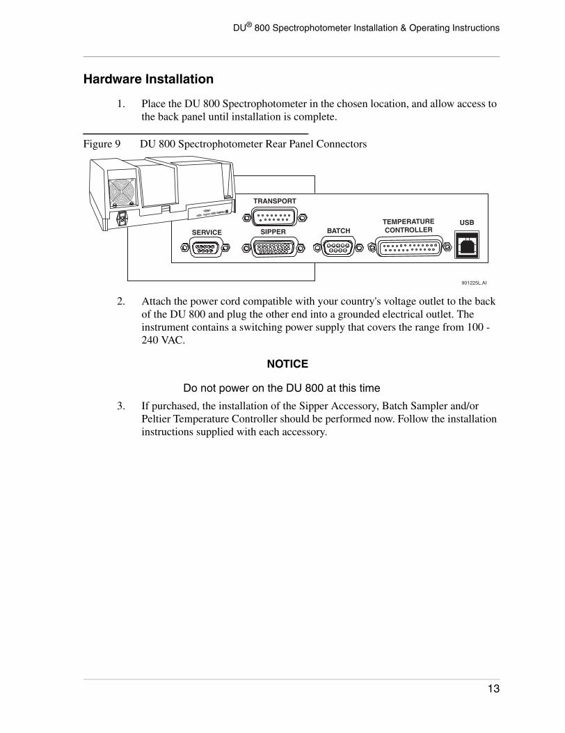
1. Place the DU 800 Spectrophotometer in the chosen location, and allow access to the back panel until installation is complete.
Figure 9 DU 800 Spectrophotometer Rear Panel Connectors
2. Attach the power cord compatible with your country's voltage outlet to the back of the DU 800 and plug the other end into a grounded electrical outlet. The instrument contains a switching power supply that covers the range from 100 - 240 VAC.
NOTICE
Do not power on the DU 800 at this time
3. If purchased, the installation of the Sipper Accessory, Batch Sampler and/or Peltier Temperature Controller should be performed now. Follow the installation instructions supplied with each accessory.
901225L.AI
SERVICE
TRANSPORT
SIPPER BATCHTEMPERATURECONTROLLER
USB
13

DU® 800 Spectrophotometer Installation & Operating Instructions
4. Place the PC in a convenient location near the DU 800 and attach the flat connector of the USB cable to the USB port of the PC. Attach the other end of the connector to the USB port located on the back of the DU 800.
Figure 10 USB Connections on the PC and Spectrophotometer
NOTICE
It is recommended that you label the USBPort on the PC as “DU 800” and always usethis port for the connection to theSpectrophotometer. Switching the cable to adifferent port after the DU 800 software isinstalled will require a manual installation ofthe drivers.
5. Setup the PC with monitor and peripherals. Make sure that it meets the minimum requirements (see Requirements, Computer). Refer to the installation instructions included with the PC, monitor and printer for information on how to setup and power on each item.
NOTICE
The monitor can be placed on the top leftside of the DU 800.
Large monitors may restrict the movementof the sample compartment cover.
901226L.AI
PERATURE NTROLLER
USB
COMPUTER SPECTROPHOTOMETER
14

DU® 800 Spectrophotometer Installation & Operating Instructions
Software Installation
1. Power on the PC.
2. Locate the DU 800 System and Applications Software CD provided in the shipping kit and place it in the CD-ROM drive of the PC.
3. The setup should start automatically after inserting the CD. If it does not, access the CD-ROM drive from Windows Explorer and click on SETUP.EXE to start the installation manually.
4. Follow the on-screen instructions to complete the software installation.
5. Power on the DU 800. The power switch is located on back of the DU 800 Spectrophotometer. The green Power LED on the front of the DU 800 will illuminate.
NOTICE
If the green Power LED does not illuminate,turn off the instrument and check the fuse.Directions for fuse replacement are providedin Maintenance, Fuse Replacement.
See Troubleshooting, Operational Failures, for a complete list of problem resolutions.
6. The PC will automatically detect the DU 800 Spectrophotometer connected via the USB port.
7. When a DU 800 is plugged into the USB port, Windows will try to identify the device and install the appropriate drivers automatically. When following the described installation procedure, the required USB drivers will be installed automatically and the installation will complete. In this case, skip the following and go to Step 8.
If the DU 800 System and Applications Software has not been installed yet or the drivers cannot be found for another reason, a window similar to the one shown below will appear and the required drivers, which are located on the DU 800 System and Applications Software CD-ROM, may be added manually. However, we highly recommend that you cancel the Found New Hardware Wizard window and install the DU 800 System and Applications Software before turning on the instrument. If manual installation is necessary, the DU 800 drivers can be found on the System and Applications Software CD-ROM in the \Window\inf and the \Window\System 32\Drivers directories.
15

DU® 800 Spectrophotometer Installation & Operating Instructions
Figure 11 Found New Hardware Wizard Screen
NOTICE
Refer to Troubleshooting, OperationalFailures if you encounter any problemsduring installation
8. You may now launch the software and operate the DU 800 Spectrophotometer (see Launch and Initialization).
16

DU® 800 Spectrophotometer Installation & Operating Instructions
Getting Started
GeneralMake sure that you have reviewed the section Introduction before you begin to explore the system and its operation.
In order to make measurements, the DU 800 System and Applications Software must be running and the DU 800 Spectrophotometer must be initialized. The section Launch and Initialization describes the necessary steps.
The following step-by-step instructions will lead you through the basic applications, using simple examples. Please refer to Applications Software for more information.
Install a cell holder in the sample compartment of the instrument. Configure the software for this particular holder in the Transport/Holder tab of the Accessories window. For the following examples, a Single Cell Holder should be installed and configured. With a Multicell Holder installed and configured, up to 12 samples can be automatically processed within a set. However, this is not described in the following step-by-step exercises. In this case, it is recommended to set the number of cells in the Sampler Tab of the Method of the selected application to 1, before starting a sample run, and use a single cell position.
By default, the system uses the <Generic User> level.
Figure 12 User Display Screen
The system includes a Visible Lamp (Tungsten) and a UV Lamp (Deuterium- Halogen). The visible lamp covers the range from 321 to 1100 nm while the UV lamp provides the energy for the wavelength range from 190 to 415 nm.
For the following examples, both lamps should be turned on. Click on the Visible icon button to turn on the visible lamp and then click on the UV icon button.
17

DU® 800 Spectrophotometer Installation & Operating Instructions
The visible lamp is turned on immediately while the UV lamp requires approximately 30 seconds warm up time before it can be used. The warm up period is indicated by the status message "Warming up UV lamp ..." while the UV icon button flashes.
When a lamp is turned on, the respective menu item is checked and the caption of the respective icon button turns red.
After the UV lamp has been warmed up the message in the Status & Control Frame reads "UV Lamp On for x sec" (the unit can be seconds, minutes, or hours). This provides additional information for the user in regard to the UV lamp warm up time.
This sections provides step-by-step operating instructions for three simple standard applications.
Taking Single Wavelength Readings
Taking a Wavelength Scan
Performing a Kinetic Run
Taking Single Wavelength ReadingsAll applications, except Wavelength Scan I and II, take one or multiple single wavelength readings in one form or another (e.g., reading at 260.0 nm and 280.0 nm).
Make sure that the Fixed Wavelength application is selected and that the current method is the <Default Method> by checking the drop-down list boxes in the Toolbar. If not, click on the down arrow of the drop-down list box and select the appropriate item. You should see a window similar to the one shown below.
18

DU® 800 Spectrophotometer Installation & Operating Instructions
Figure 13 Window with Fixed Wavelength Application Selected
You are now ready to take single wavelength readings at three wavelengths, 200.0, 250.0, and 300.0 nm. But HALT - before we take the first reading we want to change some parameters, which is done in the Method window.
Editing a Method
The <Default Method> for Fixed Wavelength provides a set of pre-defined parameters. For example, there are 3 wavelengths which are specified as 200.0, 250.0 and 300.0 nm.
We want to change these parameter to fit our requirements. Click on the Create/Edit Method menu item or the Edit Method icon button. This brings up the window shown below with the default parameters for the Fixed Wavelength application.
19
DU® 800 Spectrophotometer Installation & Operating Instructions
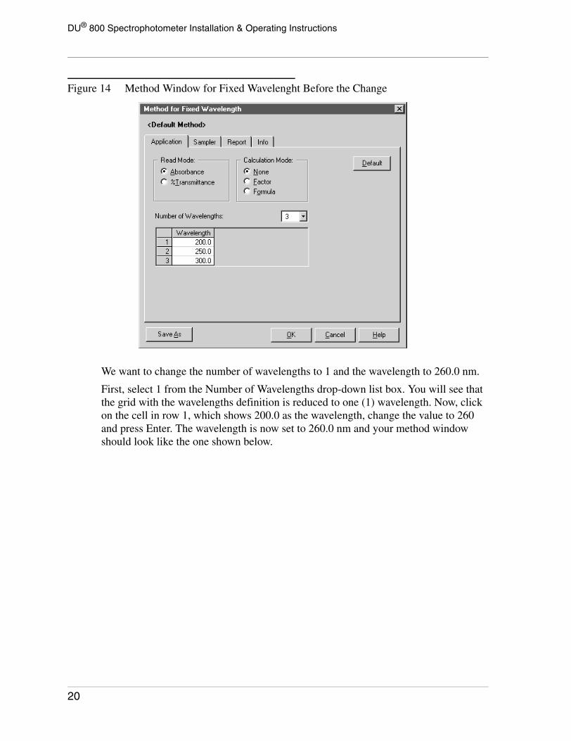
Figure 14 Method Window for Fixed Wavelenght Before the Change
We want to change the number of wavelengths to 1 and the wavelength to 260.0 nm.
First, select 1 from the Number of Wavelengths drop-down list box. You will see that the grid with the wavelengths definition is reduced to one (1) wavelength. Now, click on the cell in row 1, which shows 200.0 as the wavelength, change the value to 260 and press Enter. The wavelength is now set to 260.0 nm and your method window should look like the one shown below.
20
DU® 800 Spectrophotometer Installation & Operating Instructions
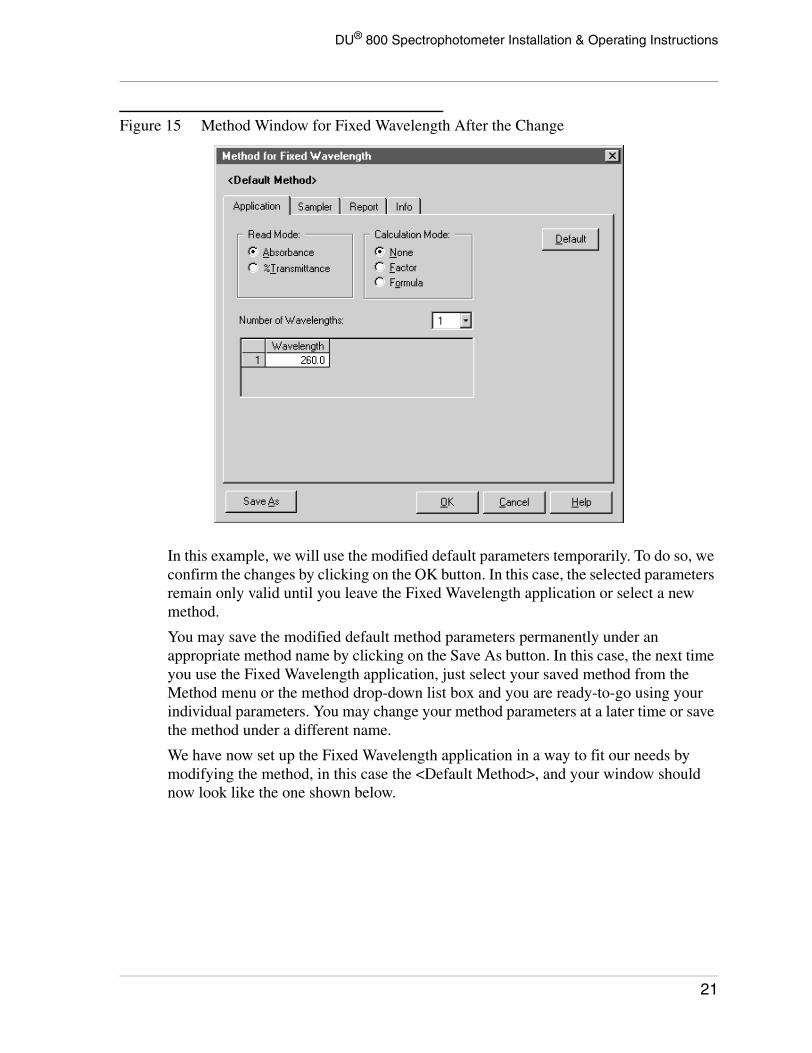
Figure 15 Method Window for Fixed Wavelength After the Change
In this example, we will use the modified default parameters temporarily. To do so, we confirm the changes by clicking on the OK button. In this case, the selected parameters remain only valid until you leave the Fixed Wavelength application or select a new method.
You may save the modified default method parameters permanently under an appropriate method name by clicking on the Save As button. In this case, the next time you use the Fixed Wavelength application, just select your saved method from the Method menu or the method drop-down list box and you are ready-to-go using your individual parameters. You may change your method parameters at a later time or save the method under a different name.
We have now set up the Fixed Wavelength application in a way to fit our needs by modifying the method, in this case the <Default Method>, and your window should now look like the one shown below.
21

DU® 800 Spectrophotometer Installation & Operating Instructions
Figure 16 Window with Fixed Wavelength Application and all Changes Made
The following three things have changed when we closed the Method window. First, the Method Parameter List has been updated. Notice that it only shows one wavelength with the entered wavelength value. Second, the data grid changed to only one column with the correct heading to reflect the current parameter settings. And third, the large-number display has only the field that is labeled with the respective unit and wavelength.
We are now ready to measure our samples using customized parameters. But before we take a reading of the first sample, we need to blank the system on the selected wavelength.
Blanking
A blank is required when lamps are turned on or certain parameters change (see Blanking Method for more information). In these cases, the instrument will remind the user with the message BLANK REQUIRED. Insert an empty cuvette or a cuvette with a blank solution in the cell holder at the measurement position and close the sample compartment.
22
DU® 800 Spectrophotometer Installation & Operating Instructions
Now click the BLANK button. The Status & Control Frame displays Blanking... during the blanking and Last blanked at 11:13 AM when it is complete. In this example, a single blank reading is taken at 260.0 nm.
The system is now ready to provide accurate readings.
Reading
Insert a cuvette containing a sample into the Single Cell Holder (or the appropriate position(s) of the Multi-Position Cell Holder) and close the sample compartment.
The Sample ID for the current sample (Sample 1-1) is a default and is shown in blue. With a Multi-Position Cell Holder, there would be a set of default Sample ID's (e.g., from Sample 1-1 to Sample 1-6). You can modify those Sample ID's that are shown in blue by clicking on the respective cell and changing the text, followed by the Enter key. This must be done before the measurement of the sample(s) and allows you to use customized Sample ID's for the entire set. After a sample reading is complete, the respective Sample ID turns black and the cell is locked.
Now click on the READ button to take a reading. After the reading has been taken, the result is reported in the data grid and the system is now ready to process the next sample (or sample set). Open the sample compartment, replace the cell with the next sample (or sample set when using a multi-position cell holder), and then close the sample compartment to read the next sample.
Your window should now look like the one shown below.
23

DU® 800 Spectrophotometer Installation & Operating Instructions
Figure 17 Window with Fixed Wavelength Application and Measurement Taken From Three Samples Using a Single Cell Holder
After we have taken the readings of all samples, we must decide what to do with the acquired data. We can discard them, print them, and/or save them. In any case, to complete the current run, select another application or method, or proceed with something else, we must execute Save and/or Clear.
Print, Save, and Clear
Print - To print the acquired data, select Print from the File menu in the Applications Frame.
24

DU® 800 Spectrophotometer Installation & Operating Instructions
Save - To save the acquired data, select Save As from the File menu in the Applications Frame or click on the Save File icon button.
The Save File dialog appears, which lets you enter an appropriate filename. Click on the OK button to save the data or Cancel to abort. If you don't change the target directory, the data file (.DUX) is saved to the following location "C:\DU800 Data\Generic User\Fixed Wavelength\<Filename>.dux", if the administrator has not changed the default DATA root directory previously.
Clear - To end the current task and reset the application (e.g.; for another task or to leave the application), select Clear from the File menu in the Applications Frame or click on the Clear icon button. A message will inform you if the data has not been saved. The data grid and the graph are cleared, any unsaved data is discarded, and the application is reset.
You may then start another Fixed Wavelength task or select another application.
Taking a Wavelength ScanIn comparison to all other applications, the Wavelength Scan application (I or II) takes scans, which are represented by a continuous wavelength range (e.g., readings from 200.0 nm to 800.0 nm in 1.0 nm intervals).
Make sure that the Wavelength Scan application is selected and that the current method is the <Default Method> by checking the drop-down list boxes in the Toolbar. If not, click on the down arrow of the drop-down list box and select the appropriate item. You should see a window similar to the one shown below.
25
DU® 800 Spectrophotometer Installation & Operating Instructions
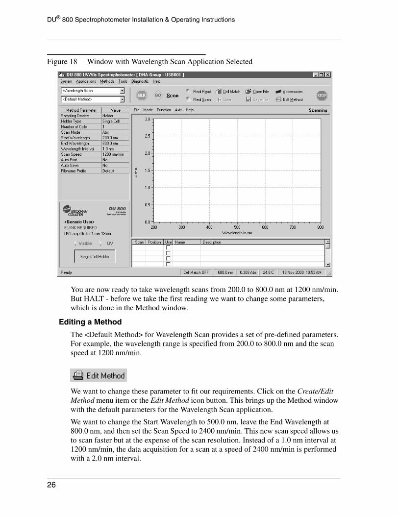
Figure 18 Window with Wavelength Scan Application Selected
You are now ready to take wavelength scans from 200.0 to 800.0 nm at 1200 nm/min. But HALT - before we take the first reading we want to change some parameters, which is done in the Method window.
Editing a Method
The <Default Method> for Wavelength Scan provides a set of pre-defined parameters. For example, the wavelength range is specified from 200.0 to 800.0 nm and the scan speed at 1200 nm/min.
We want to change these parameter to fit our requirements. Click on the Create/Edit Method menu item or the Edit Method icon button. This brings up the Method window with the default parameters for the Wavelength Scan application.
We want to change the Start Wavelength to 500.0 nm, leave the End Wavelength at 800.0 nm, and then set the Scan Speed to 2400 nm/min. This new scan speed allows us to scan faster but at the expense of the scan resolution. Instead of a 1.0 nm interval at 1200 nm/min, the data acquisition for a scan at a speed of 2400 nm/min is performed with a 2.0 nm interval.
26

DU® 800 Spectrophotometer Installation & Operating Instructions
First, change the Start Wavelength to 500.0 nm. Then change the scan speed to 2400 nm/min. Select 2400 from the Scan Speed drop-down list box. The Interval value will be recalculated and should now show 2.0 nm as in the following window.
Figure 19 Method Window for Wavelength Scan After the Change
In this example, we will use the modified default parameters temporarily. To do so, we confirm the changes by clicking on the OK button. In this case, the selected parameters remain only valid until you leave the Wavelength Scan application or select a new method.
You may save the modified default method parameters permanently under an appropriate method name by clicking on the Save As button. In this case, the next time you use the Wavelength Scan application, just select your saved method from the Method menu or the method drop-down list box and you are ready-to-go using your individual parameters. You may change your method parameters at a later time or save the method under a different name.
We have now set up the Wavelength Scan application in a way to fit our needs by modifying the method, in this case the <Default Method>. The current parameter settings are reflected in the Method Parameters Frame.
27

DU® 800 Spectrophotometer Installation & Operating Instructions
Figure 20 Method Parameters Frame After the Change
The Method Parameters Frame has been updated when we closed the Method window. Notice that it now shows the Start Wavelength with 500.0 nm, the Wavelength Interval with 2.0 nm, and the Scan Speed with 2400 nm/min.
We are now ready to scan our samples using customized parameters. But before we take a scan of the first sample, we need to blank the system with the selected wavelength range.
Blanking
A blank is required when lamps are turned on or certain parameters change (see Blanking Method for more information). In these cases, the instrument will remind the user with the message BLANK REQUIRED. Insert an empty cuvette or a cuvette with a blank solution in the cell holder at the measurement position and close the sample compartment.
Now click the BLANK icon button. The Status & Control Frame displays Blanking... when a blank is taken and Last blanked at 11:13 AM when it is completed. In this example, a blank scan is taken from 500.0 nm to 800.0 nm with an interval of 2.0 nm at a scan speed of 2400 nm/min.
The system is now ready to provide accurate scans.
Scanning
Insert a sample into the Single Cell Holder (or the appropriate position(s) of the Multi-Position Cell Holder) and close the sample compartment.
28

DU® 800 Spectrophotometer Installation & Operating Instructions
The grid below the scan window will be automatically populated when we take scans. The Use check box allows you to select if the scan should be used and displayed or not. By default, each acquired scan will be used and displayed.
Now click on the SCAN button to take a scan. You can see how the readings for each wavelength within the range are taken in real time. If the Dynamic Autoscaling item in the Axis menu is checked, the y-axis will be automatically resized during the scanning process. If not, you can select the Autoscale Y item in the Axis menu to autoscale the y-axis manually when the scan is finished.
You may now open the sample compartment, replace the cell with the next sample (or sample set when using a multi-position cell holder), and then close the sample compartment to read the next sample.
Your window should now look like the one shown below.
Figure 21 Window with Wavelength Scan Application and Scans Taken From Three Samples Using a Single Cell Holder
After we have taken the scans of all samples, we must decide what to do with the acquired scans. We can discard them, print them, and/or save them. In any case, to complete the current run, select another application or method, or proceed with something else, we must execute Save and/or Clear.
29

DU® 800 Spectrophotometer Installation & Operating Instructions
Print, Save, and Clear
Print - To print the acquired data, select Print from the File menu in the Applications Frame.
Save - To save the acquired data, select Save As from the File menu in the Applications Frame or click on the Save File icon button.
The Save File dialog appears, which lets you enter an appropriate filename. Click on the OK button to save the data or Cancel to abort. If you don't change the target directory, the data file (.DUX) is saved to the following location "C:\DU800 Data\Generic User\Wavelength Scan\<Filename>.dux", if the administrator has not changed the default DATA root directory previously.
Clear - To end the current task and reset the application (e.g.; for another task or to leave the application), select Clear from the File menu in the Applications Frame or click on the Clear icon button. A message will inform you if the data has not been saved. The data grid and the graph are cleared, any unsaved data is discarded, and the application is reset.
You may then start another Wavelength Scan task or select another application.
Performing a Kinetic RunAll applications, except Wavelength Scan, take single wavelength readings in one form or another. A Kinetics Run observes the absorbance of a single wavelength from a sample and uses the change of the absorbance over time to calculate a rate, usually expressed as dAbs/min or dA/min.
Make sure that the Kinetics/Time application is selected and that the current method is the <Default Method> by checking the drop-down list boxes in the Toolbar. If not,
30

DU® 800 Spectrophotometer Installation & Operating Instructions
click on the down arrow of the drop-down list box and select the appropriate item. You should see a window similar to the one shown below.
Figure 22 Window with Kinetics/Time Application Selected
You are now ready to start the Kinetic run. But HALT - before we take the first reading we want to change some parameters, which is done in the Method window.
Editing a Method
The <Default Method> for Kinetics/Time provides a set of pre-defined parameters. For example, in the <Default Method>, the analytical wavelength is set to 540.0 nm and samples are supposed to be observed over a total time of 120 seconds, taking a measurement for each sample every 15 seconds. In addition, we want to monitor the rate during the run to see if the absorbance change over time is within the expected range.
We want to change these parameter to fit our requirements. Click on the Create/Edit Method menu item or the Edit Method icon button. This brings up the window shown below with the default parameters for the Kinetics/Time application.
31

DU® 800 Spectrophotometer Installation & Operating Instructions
Figure 23 Method Window for Kinetics/Time Before the Change
We want to change the number of samples to 1 and correct the measurement for background at 480.0 nm.
First, click on the Background Wavelength field and enter 480. Then check the Background Correction box to determine that a measurement will also be taken at the background wavelength of 480.0 nm, in addition to the measurement at the analytical wavelengths. The result of the two measurements will be an absorbance corrected for background, a so called Net Absorbance (absorbance - background absorbance).
Second, click on the Samples field in the Kinetic frame and enter 1. This determines that the Kinetic run will consist of a single sample.
Third, change the Interval Time and Total Time to values that better suit this experiment. Set the Interval Time to 5 seconds and the Total Time to 60 seconds.
Finally, check the Delta Abs box so we can monitor the rate (dAbs/min) for each time point, starting with the second. This absorbance change at any time point gives us an indication about the time course of the kinetics and would allow us to make a decision in order to abort the kinetic run, if the rate of the absorbance change is not what we expect it to be.
All parameters have been set and your method window should look like the one shown below.
32

DU® 800 Spectrophotometer Installation & Operating Instructions
Figure 24 Method Window for Kinetics After the Change
In this example, we will use the modified default parameters temporarily. To do so, we confirm the changes by clicking on the OK button. In this case, the selected parameters remain only valid until you leave the Kinetics/Time application or select a new method.
You may save the modified default method parameters permanently under an appropriate method name by clicking on the Save As button. In this case, the next time you use the Kinetics/Time application, just select your saved method from the Method menu or the method drop-down list box and you are ready-to-go using your individual parameters. You may change your method parameters at a later time or save the method under a different name.
We have now set up the Kinetics/Time application in a way to fit our needs by modifying the method, in this case the <Default Method>, and your window should now look like the one shown below.
33

DU® 800 Spectrophotometer Installation & Operating Instructions
Figure 25 Window with Kinetics/Time Application and All Changes Made
The following three things have changed when we closed the Method window. First, the Method Parameter List has been updated. Notice that it display the parameters we have changed earlier in the method. Second, the dAbs/min column has been added to the data grid (for each sample, if we would have multiple samples).
We are now ready to start the kinetics run using the customized parameters. But before we do that, we need to blank the system on the selected wavelengths (the analytical and the background wavelength).
Blanking
A blank is required when lamps are turned on or certain parameters change (see Blanking Method for more information). In these cases, the instrument will remind the user with the message BLANK REQUIRED. Insert an empty cuvette or a cuvette with a blank solution in the cell holder at the measurement position and close the sample compartment.
34
DU® 800 Spectrophotometer Installation & Operating Instructions
Now click the BLANK button. The Status & Control Frame displays “Blanking ...” during the blanking and “Last blanked at 11:13 AM” when it is complete. In this example, two blank readings are taken - one at 540.0 nm and one at 480.0 nm.
The system is now ready to provide accurate readings.
Reading
Insert a cuvette containing a sample into the Single Cell Holder (or the appropriate position(s) of the Multi-Position Cell Holder) and close the sample compartment.
To simulate a kinetic reaction, we need a sample that changes absorbance over time. For this example, we will add a small amount of coffee creamer (any brand will do) to the top of a cuvette filled with water. Do not shake the cuvette. The dispersion of creamer will cause a change in absorbance over time. Begin the run as soon as possible after adding the creamer. Don't forget to close the door of the sample compartment before you start the run.
Also, make sure to click the Dynamic Autoscaling item in the Axis menu to ensure that you will see the kinetic data in the graph window during the run.
Now click on the READ button to start the kinetic run. As determined in the method, this will take approximately 60 seconds. During the run, the absorbances and the calculated rates for each time point (dAbs/min) are displayed in the data grid. You should also see the net absorbances in the graph window. After all readings have been taken within the run, the Rates item in the Mode menu will be enabled.
You now have three modes available and the windows should look like the ones below:
35

DU® 800 Spectrophotometer Installation & Operating Instructions
1. The Data Acquisition mode, which we have just completed.
Figure 26 Data Acquisition Mode
36

DU® 800 Spectrophotometer Installation & Operating Instructions
2. The Rates mode, which shows the rate(s) or result(s).
Figure 27 Rates Mode
3. The Raw Data mode. We can switch back and forth between the modes to display the acquired data or the calculated rate(s) or result(s).
After we have finished the kinetic run, we must decide what to do with the acquired data and results. We can discard them, print them, and/or save them. In any case, to complete the current run, select another application or method, or proceed with something else, we must execute Save and/or Clear.
37

DU® 800 Spectrophotometer Installation & Operating Instructions
Print, Save, and Clear
Print - To print the acquired data, select Print from the File menu in the Applications Frame.
Save - To save the acquired data, select Save As from the File menu in the Applications Frame or click on the Save File icon button.
The Save File dialog appears, which lets you enter an appropriate filename. Click on the OK button to save the data or Cancel to abort. If you don't change the target directory, the data file (.DUX) is saved to the following location "C:\DU800 Data\Generic User\Kinetics\<Filename>.dux", if the administrator has not changed the default DATA root directory previously.
Clear - To end the current task and reset the application (e.g.; for another task or to leave the application), select Clear from the File menu in the Applications Frame or click on the Clear icon button. A message will inform you if the data has not been saved. The data grid and the graph are cleared, any unsaved data is discarded, and the application is reset.
You may then start another Kinetics/Time run or select another application.
38

DU® 800 Spectrophotometer Installation & Operating Instructions
System Software
GeneralThe CD-ROM includes the DU 800 System and Applications Software setup files, the installation and operating instructions and all installation instructions for accessories as Adobe Acrobat (PDF) files. This section focuses on System Software and describes the user interface and generic functionality. The applications are described in Applications Software.
The software has been optimized for a screen resolution of 800 x 600 pixels or higher as well as the use of “Small Fonts”. With a lower resolution, the main window will not fit on the screen and the selection of “Large Fonts” or “Other” will result in the misalignment of controls.
Default Directories
By default, the software will be installed in the Program Files path or the path specified during setup. The default installation directory is "DU800 System". Subdirectories and files that are created and kept beneath this directory, such as methods, etc., are considered system-related and not data-related.
Directory Level DescriptionC:\
Program Files
DU800 System INSTALL Root
Audit Trail For Audit Trail files
DU800 Audit Trail.log
System Backup Files For Backup/Export files
My System backup.bkx
Custom Applications Holds custom applications
Diluted DNA.mth
Methods
Generic User Methods Directory, Generic Level
Fixed Wavelength
My Mehod #1.mth
My Method #2.mth
Wavelength Scan
My Method #1.mth
Administrator Methods Directory, Administrator Level
User Name #1 Methods Directory, User Level
User Name #2 Methods Directory, User Level
Executable Includes Program Files (don’t touch)
Help Includes HTML Help File(s)
PDF Adobe Acrobat PDF Files
39
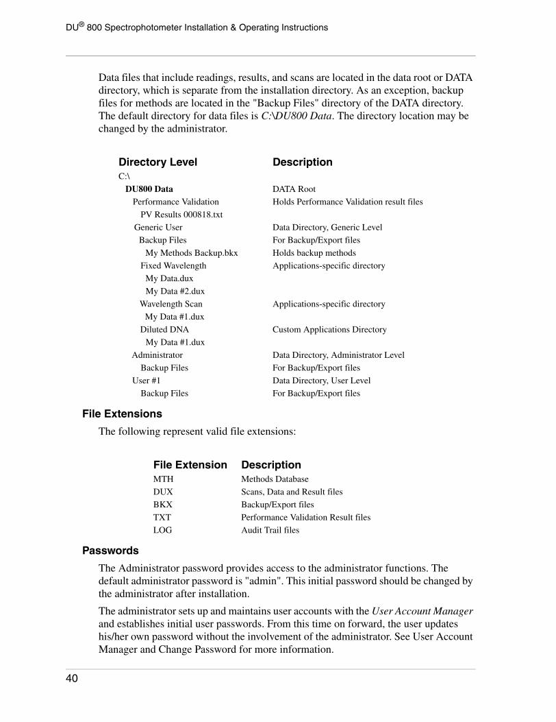
DU® 800 Spectrophotometer Installation & Operating Instructions
Data files that include readings, results, and scans are located in the data root or DATA directory, which is separate from the installation directory. As an exception, backup files for methods are located in the "Backup Files" directory of the DATA directory. The default directory for data files is C:\DU800 Data. The directory location may be changed by the administrator.
File Extensions
The following represent valid file extensions:
Passwords
The Administrator password provides access to the administrator functions. The default administrator password is "admin". This initial password should be changed by the administrator after installation.
The administrator sets up and maintains user accounts with the User Account Manager and establishes initial user passwords. From this time on forward, the user updates his/her own password without the involvement of the administrator. See User Account Manager and Change Password for more information.
Directory Level DescriptionC:\
DU800 Data DATA Root
Performance Validation Holds Performance Validation result files
PV Results 000818.txt
Generic User Data Directory, Generic Level
Backup Files For Backup/Export files
My Methods Backup.bkx Holds backup methods
Fixed Wavelength Applications-specific directory
My Data.dux
My Data #2.dux
Wavelength Scan Applications-specific directory
My Data #1.dux
Diluted DNA Custom Applications Directory
My Data #1.dux
Administrator Data Directory, Administrator Level
Backup Files For Backup/Export files
User #1 Data Directory, User Level
Backup Files For Backup/Export files
File Extension DescriptionMTH Methods Database
DUX Scans, Data and Result files
BKX Backup/Export files
TXT Performance Validation Result files
LOG Audit Trail files
40

DU® 800 Spectrophotometer Installation & Operating Instructions
The Service Diagnostic programs are password-protected and are only available to Beckman Coulter service personnel.
Logon Levels
The DU 800 includes three levels of operation. In all three levels, all available applications are fully accessible using the default settings.
Generic or <Generic User> - This is the default level and provides no methods/data protection and no user customization.
User - A user may log on with a user name and password. The initial password is supplied by the administrator. Only methods belonging to the individual user are shown and data are accessed and stored in user-specific directories. Each user can set and use his/her own preferences in User Options.
A group of users, such as personnel of a specific lab, could also be considered as a single user. Simply choose an appropriate name and share the password with the group.
Administrator - The administrator may log on as "Administrator" and the administrator password. Only methods belonging to the administrator are shown and data are accessed and stored using the administrator subdirectory. The administrator can set the system preferences in System Options. The system options apply to the <Generic User> and serve as the default preferences for the User Options.
See User Logon / Change User for more information.
On-Line Launch (with System Initialization)The DU 800 Spectrophotometer is initialized by the Windows software when it is detected on the USB port. It is recommended to turn the instrument on before launching the software.
NOTICE
Lift the sample compartment cover of theDU 800 Spectrophotometer and verify thatthere is nothing in the sample compartmentthat can block the light beam.After turning on the DU 800Spectrophotometer for the first time, waitapproximately 7 seconds before starting thesoftware. Failing to do so, may result in themessage “Another program is alreadyrunning” or the system just sits there withoutinitializing. In this case, close the software,turn the spectrophotometer OFF, wait acouple of seconds, and then turn it ONagain. After waiting for approximately 7seconds, start the software.
41
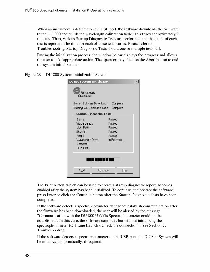
DU® 800 Spectrophotometer Installation & Operating Instructions
When an instrument is detected on the USB port, the software downloads the firmware to the DU 800 and builds the wavelength calibration table. This takes approximately 3 minutes. Then, various Startup Diagnostic Tests are performed and the result of each test is reported. The time for each of these tests varies. Please refer to Troubleshooting, Startup Diagnostic Tests should one or multiple tests fail.
During the initialization process, the window below displays the progress and allows the user to take appropriate action. The operator may click on the Abort button to end the system initialization.
Figure 28 DU 800 System Initialization Screen
The Print button, which can be used to create a startup diagnostic report, becomes enabled after the system has been initialized. To continue and operate the software, press Enter or click the Continue button after the Startup Diagnostic Tests have been completed.
If the software detects a spectrophotometer but cannot establish communication after the firmware has been downloaded, the user will be alerted by the message "Communication with the DU 800 UV/Vis Spectrophotometer could not be established". In this case, the software continues but without initializing the spectrophotometer (Off-Line Launch). Check the connection or see Section 7. Troubleshooting.
If the software detects a spectrophotometer on the USB port, the DU 800 System will be initialized automatically, if required.
42

DU® 800 Spectrophotometer Installation & Operating Instructions
After the system has been initialized and communication with the spectrophotometer is lost, for one reason or another, the user will be alerted by the message "Communication with the spectrophotometer has been lost. Please check the connection". The software re-establishes communication with the spectrophotometer automatically when the connection is restored.
Off-Line Launch
When no instrument is detected on the USB port, the software is launched in off-line mode.
This would be the case when the software has been installed on another PC for post-run analysis or other purposes. The fact that the software is running in off-line mode is indicated in the software caption.
Common Front End
User Interface
The DU 800 System and Applications Software integrates all system functionality and the various applications in a common user interface (front-end). This allows the user to operate all aspects of the system from a single vantage point. The integrated user interface includes key control elements, common to all applications.
The front-end and other system-related functions are described in the System Software section.
The standard applications are available with the DU 800 System and Applications Software installation. Standard and optional applications are described in the Applications Software section. Optional applications or software options can be added via a license contained on a floppy disk. The addition or installation of software options is described in Add Software Options.
The desired application is selected from the applications menu or a drop-down list box. When selecting or initializing an application the <Default Method> will be applied and the Applications Area, which includes the Applications Menu Bar and the Data/Scan Area, will reflect the functionality of the application as described in this section.
43

DU® 800 Spectrophotometer Installation & Operating Instructions
Figure 29 Integrated Frame-Oriented User Interface
Some commands and functions, such as Blank, Read, Stop, Save File, Open File, etc., apply to all applications and are described in Toolbar and Icons.
Main Menu - The top menu provides access to system-wide functions.
Method Parameters Frame - This list box displays relevant method parameters at all times.
Status & Control Frame - Displays the status of the system (User Logon, Blank Status, UV Lamp Status) and provides common control functions.
Toolbar and Icons - The toolbar at the top of the screen, just below the main menu, provides quick access to key elements related to the operation of the system and application.
Applications Frame - The applications frame holds the applications menu bar, all elements related to the selected application, and displays the acquired data.
Permanent Status Bar - The status bar at the bottom displays system parameters and messages.
Main MenuThe main menu provides access to all functions.
44

DU® 800 Spectrophotometer Installation & Operating Instructions
During an "open run", functions in the Applications and Methods items are disabled. They will be enabled again when the user executes the Clear command, which "closes" the run. To switch to another application or select another method, the user must first close any open run. When the instrument is busy measuring samples, functions that may interfere are disabled temporarily.
Toolbar and IconsThe toolbar is fixed and cannot be removed by the user. It provides shortcuts for a number of common functions, such as BLANK, READ, and STOP buttons. In addition, other common functions can be accessed from the toolbar.
The top drop-down list box in the toolbar contains the Applications and provides the same functionality as the Applications menu item. The lower drop-down list box in the toolbar contains the Methods and provides the same functionality as some of the Methods menu items.
BLANK, (GO) READ/SCAN, and STOP Buttons
Blank, Read or Scan, and Stop are the most common commands and are executed through large icon buttons.
Read is used as the caption for the GO button for all applications, except Wavelength Scan. The Wavelength Scan application uses Scan as the caption for the GO button. Blank will blank on one or multiple single wavelengths (read blank) or a wavelength range (scan blank), depending on the application.
During data acquisition, the Stop button is enabled and halts the measurement when the current readings for the selected wavelengths have been completed or at the next possible stop point for a scan. Complete scan data that have been acquired will be retained and the user makes the choice to save or discard the data.
During an "open run" and "data acquisition", certain controls are disabled and cannot be used in order to protect the process.
The start of an "open run" is the measurement of the first sample. The run will be "closed" when the Clear command is given, usually after the data has been saved. The time in between is defined as an "open run".
For a definition of "open run", "data acquisition", and other terms, please refer to Terminology.
45
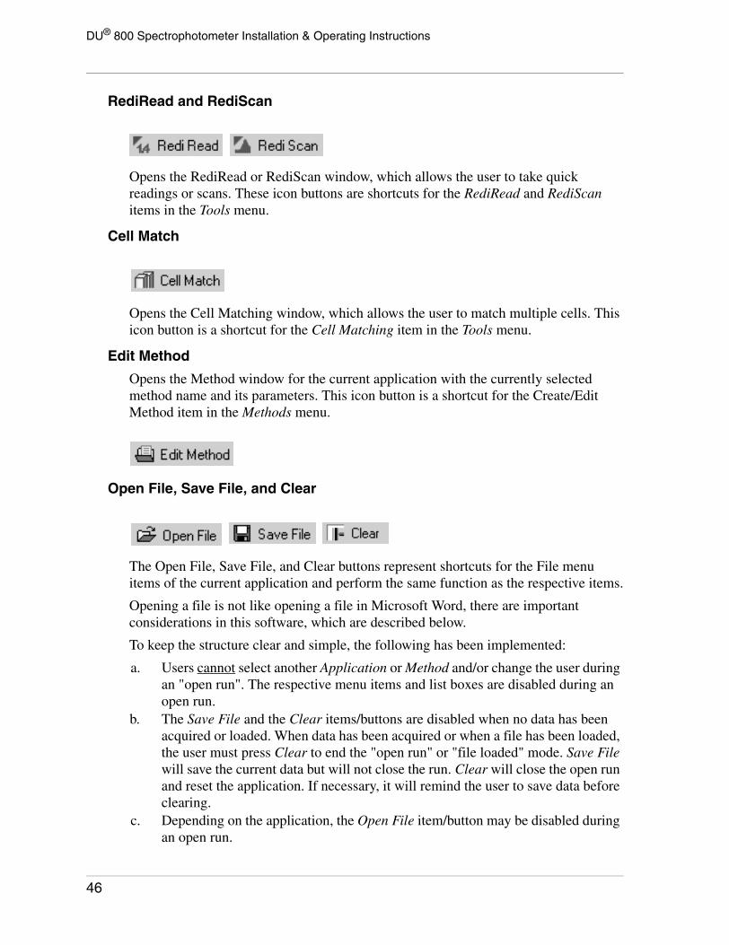
DU® 800 Spectrophotometer Installation & Operating Instructions
RediRead and RediScan
Opens the RediRead or RediScan window, which allows the user to take quick readings or scans. These icon buttons are shortcuts for the RediRead and RediScan items in the Tools menu.
Cell Match
Opens the Cell Matching window, which allows the user to match multiple cells. This icon button is a shortcut for the Cell Matching item in the Tools menu.
Edit Method
Opens the Method window for the current application with the currently selected method name and its parameters. This icon button is a shortcut for the Create/Edit Method item in the Methods menu.
Open File, Save File, and Clear
The Open File, Save File, and Clear buttons represent shortcuts for the File menu items of the current application and perform the same function as the respective items.
Opening a file is not like opening a file in Microsoft Word, there are important considerations in this software, which are described below.
To keep the structure clear and simple, the following has been implemented:
a. Users cannot select another Application or Method and/or change the user during an "open run". The respective menu items and list boxes are disabled during an open run.
b. The Save File and the Clear items/buttons are disabled when no data has been acquired or loaded. When data has been acquired or when a file has been loaded, the user must press Clear to end the "open run" or "file loaded" mode. Save File will save the current data but will not close the run. Clear will close the open run and reset the application. If necessary, it will remind the user to save data before clearing.
c. Depending on the application, the Open File item/button may be disabled during an open run.
46

DU® 800 Spectrophotometer Installation & Operating Instructions
d. All data files are associated with an application. When opening a file, the associated application is launched automatically, if required.
When a file has been opened, the following happens:
1. The methods drop-down list displays the filename instead of the method. This clearly indicates a "file loaded" mode instead of the regular "read mode". The displayed parameters are the file parameters, not the method parameters, and there is no link to a method name.
2. Applications and Methods menu items and list boxes will be disabled. The Edit Method icon button is enabled to allow post-run analysis. It also allows the user to create a new method based on the loaded file parameters.
3. Parameters stored within the file will be displayed in the Method Parameters list box. However, the "Method Parameter" column will be renamed to "File Parameter".
4. Measurement controls, such as READ or SCAN, are used to take readings or scans. These controls are disabled when a file has been loaded.
5. In the Method window, parameters such as Analytical Wavelength, etc. are locked when a file has been opened because they are related to measured data. Parameters that remain open can be modified to perform a post-run analysis. The data may then be saved under a different filename.
6. NO MEASUREMENTS CAN BE TAKEN WHEN A FILE HAS BEEN LOADED.
When opening a file or saving data, the initial directory is the applications-specific directory under the DATA root. Each logged-on user has his/her individual directories. These data directories are created automatically within each user directory and will be accessed by default for opening and saving data files.
The default directory for data is the user's directory in the DATA root.
If the DATA root is an UNC path and the system cannot connect to the network, the user will receive the message: "Cannot currently connect to the network! Do you want to use the local drive temporarily? [Yes] [No]. If yes, the default root or program directory will be used.
NOTICE
Existing DUX files cannot be overwritten.Trying to save a file under the same namewill prompt the user to specify a newfilename. When a file is saved by a user withSignature Privilege, the Add ElectronicSignature dialog is displayed.
47
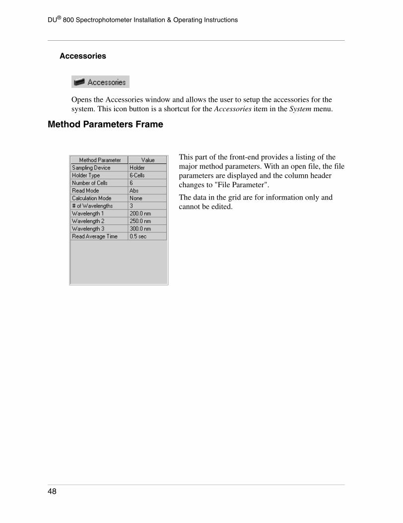
DU® 800 Spectrophotometer Installation & Operating Instructions
Accessories
Opens the Accessories window and allows the user to setup the accessories for the system. This icon button is a shortcut for the Accessories item in the System menu.
Method Parameters Frame
This part of the front-end provides a listing of the major method parameters. With an open file, the file parameters are displayed and the column header changes to "File Parameter".
The data in the grid are for information only and cannot be edited.
48

DU® 800 Spectrophotometer Installation & Operating Instructions
Status & Control Frame
Status Information
User Status
The current user is displayed in the User Status label. When no user is logged on, the system is in the <Generic User> mode. The above frame shows the system in generic user mode.
Blank Status
The blank status is shown in the Blank Status label and provides the time for the last blank. Initially, it reads BLANK REQUIRED and when the blank flag has been reset by the program. Each time a parameter changes that can affect the reading, the blank flag will be reset.
During the time it takes to read a blank, the label reads Blanking … and Last Blanked at <time> when a blank has been obtained. The time format depends on the international settings of Windows.
UV Lamp Status
When the UV lamp is off, the UV lamp status label is empty. During the warm-up phase of the UV lamp, the UV Lamp Status label reads Warming up UV lamp … and the icon on the respective source button flashes slowly.
After the warm-up, the label reads UV Lamp On for <time>.
Status & Control Elements
Sources
The Visible and the UV sources are represented by icon buttons. They provide both, feedback and control. The sources can be turned on or off independently using the icon buttons or the items in the system menu. The visible lamp is executed instantly. The UV lamp requires a minimum warm-up time of 30 seconds; however, a 30 minute warm-up time is recommended.
This part of the front-end combines important status information with the control of key spectrophotometer elements, such as sources and sampling device.
49

DU® 800 Spectrophotometer Installation & Operating Instructions
Holders
The currently selected cell holder is displayed in the Status & Control Frame. Buttons are used for the available cell positions and HOME. The current cell position is indicated by a button in the pressed state. With a transport, the HOME button is shown. HOME re-aligns the transport and moves the transport to a fixed location. Notice that HOME is not a measurement position.
The user may control the transport or cell positions using the cell buttons when "Manual" has been selected as the Number of Cells Used in the method. Single cell holders are represented by a single position.
The Cell Holder elements are as follows:
Any Cell Holder on a Static Mount An Auto 6-Cell Holder on a Transport
Any Single Cell Holder on a Transport An Auto 12-Cell Holder on a Transport
50
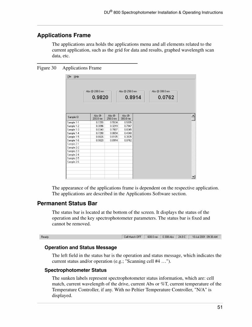
DU® 800 Spectrophotometer Installation & Operating Instructions
Applications FrameThe applications area holds the applications menu and all elements related to the current application, such as the grid for data and results, graphed wavelength scan data, etc.
Figure 30 Applications Frame
The appearance of the applications frame is dependent on the respective application. The applications are described in the Applications Software section.
Permanent Status BarThe status bar is located at the bottom of the screen. It displays the status of the operation and the key spectrophotometer parameters. The status bar is fixed and cannot be removed.
Operation and Status Message
The left field in the status bar is the operation and status message, which indicates the current status and/or operation (e.g.; "Scanning cell #4 …").
Spectrophotometer Status
The sunken labels represent spectrophotometer status information, which are: cell match, current wavelength of the drive, current Abs or %T, current temperature of the Temperature Controller, if any. With no Peltier Temperature Controller, "N/A" is displayed.
51

DU® 800 Spectrophotometer Installation & Operating Instructions
System Menu
User Logon / Change User
The <Generic User>, which is the default, is not considered a logged-on user. Therefore, in the <Generic User> mode, the menu item reads User Logon. When logged on as a user or administrator, the caption changes to Change User and the Change Password and the Log Off items become enabled.
Figure 31 User Logon Screen
The Logon User and Change User items perform identical functions, only the terminology is different.
Change Password
Each user is able to change his/her password at any time. Title 21 Code of Federal Regulations (21 CFR Part 11) Electronic Records; Electronic Signatures requires the periodic change of the user password. See System Options, Regulatory Tab for the necessary setup.
52

DU® 800 Spectrophotometer Installation & Operating Instructions
Figure 32 Change Password for Administrator Screen
The OK button is disabled until the number of characters in the Confirm New Password field is identical to the Enter New Password field.
A user account must be established by the administrator before a user can log on. The User Account Manager, which allows the creation of user accounts, is strictly an administrator function.
Log Off
The Log Off item returns the system to the <Generic User> mode and the Fixed Wavelength application.
Sources
The menu items UV Source and Visible Source allow the operator to turn the lamps on and off. The respective icon buttons in the Status & Control Frame perform the identical functions. Check marks are used to indicate the status of the lamps.
Accessories
The Accessories item allows access to the setup window for the system accessories. The installed accessories must be defined for the system to function properly. After making any hardware changes to the DU 800, such as changing the cell holder or installing a sipper, the appropriate tab of the accessories window must be updated.
Shortcut for Accessories.
For more information on the Accessories setup, refer to:
• Transport and Holders• Sipper Accessory• Batch Sampler• Peltier Temperature Controller
53

DU® 800 Spectrophotometer Installation & Operating Instructions
Exit
Exits the DU 800 System and Applications Software. Before exiting, the system will prompt the user when data has not been saved.
Transport/HolderDepending on the mode, the software automatically detects the presence and type of the Transport. The proper selection is made automatically in the Transport/Holder tab. The user must still select the Holder that is mounted on the transport.
On-Line Mode: Transport is detected automatically; user cannot select it.
Off-Line Mode: Transport is set to “None”; user cannot select it.
Figure 33 Accessories Screen with Transport/Holder Tab Selected
The current Cell Holder must be defined by the user. Based on the Transport, the compatible cell holder items are enabled and the installed cell holder can be selected. For example, a multi-position cell holder can only be selected if a transport is installed or has been selected. The Tm Microcell Holder can only be selected if the High Performance Transport is installed and selected.
See Sampling Accessories, Cell Holders for additional information.
With the selection of the Custom Cell Holder, the custom cell holder frame becomes visible and the position for each cell location can be defined in millimeters. A custom cell holder can have a maximum of 12 positions. The cell locations must be within the range of 0 to 112 mm.
54

DU® 800 Spectrophotometer Installation & Operating Instructions
The Manual Position Control determines the cell position in mm. The Enter key or the Apply button will execute the command and move the transport to the specified position. The input range is from 0 to 112 mm.
SipperThe Sipper Accessory uses a peristaltic pump to aspirate the sample into a flow cell for measurement in the DU 800. The sipper is used to semi-automate the task of measuring a large number of samples. The Sipper Installed item must be checked when a sipper is installed.
Figure 34 Accessories Screen with Sipper Tab Selected
Fill Time - The fill time is the amount of time, in seconds, that the pump runs to aspirate a sample into the flow cell. The fill time also determines the amount of sample that is aspirated. The more viscous the sample, the longer the pump will need to fill to aspirate a given volume. The recommended minimum sample volume with a sipper is 1.0 mL.
If the sample will be returned after analysis, to minimize contamination, the sample solution should fill the inlet tubing, the flow cell, and the outlet tubing, but not enter the pump tubing.
If the sample volume is critical, the amount of time required to aspirate that amount of sample should be checked periodically.
Return Time - The return time is the amount of time, in seconds, that the pump returns the sample when [RETURN] is pressed. It is normally set to equal or slightly greater than the fill time.
55
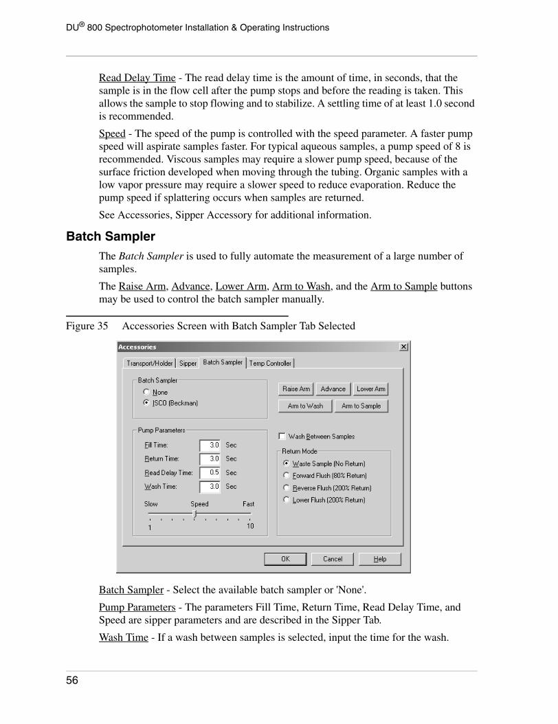
DU® 800 Spectrophotometer Installation & Operating Instructions
Read Delay Time - The read delay time is the amount of time, in seconds, that the sample is in the flow cell after the pump stops and before the reading is taken. This allows the sample to stop flowing and to stabilize. A settling time of at least 1.0 second is recommended.
Speed - The speed of the pump is controlled with the speed parameter. A faster pump speed will aspirate samples faster. For typical aqueous samples, a pump speed of 8 is recommended. Viscous samples may require a slower pump speed, because of the surface friction developed when moving through the tubing. Organic samples with a low vapor pressure may require a slower speed to reduce evaporation. Reduce the pump speed if splattering occurs when samples are returned.
See Accessories, Sipper Accessory for additional information.
Batch SamplerThe Batch Sampler is used to fully automate the measurement of a large number of samples.
The Raise Arm, Advance, Lower Arm, Arm to Wash, and the Arm to Sample buttons may be used to control the batch sampler manually.
Figure 35 Accessories Screen with Batch Sampler Tab Selected
Batch Sampler - Select the available batch sampler or 'None'.
Pump Parameters - The parameters Fill Time, Return Time, Read Delay Time, and Speed are sipper parameters and are described in the Sipper Tab.
Wash Time - If a wash between samples is selected, input the time for the wash.
56
DU® 800 Spectrophotometer Installation & Operating Instructions
Wash Between Samples - If the batch sampler has a wash station, a wash between each sample can be selected by checking the box.
Return Mode - Select the desired Return Mode by clicking on the respective radio button. The percentage values are that of the sipper fill time.
The return modes have the following uses and limitations:
Waste Sample - Flushes the sample to waste for 5 seconds.
No Return
- Raise arm- Flush 5 seconds
Forward Flush - Returns most of the sample with the aspirator arm lowered, raises the aspirator arm to finish returning the sample, then flushes to waste to remove the maximum amount of sample from the tubing.
80% Return
- Raise arm- Wait 1 second- Return 20%- Wait 1 second- Return 20%- Wait 1 second- Flush 100%
Forward Flush will not aerate the sample, but has the possibility of creating aerosols and does send the sample through the pump tubing.
Reverse Flush - Returns all of the sample with the aspirator arm lowered, then raises the aspirator arm and attempts to remove the maximum amount of sample from the tubing.
200% Return
- Raise arm- Wait 1 second- Return 20%- Wait 1 second- Return 20%- Wait 1 second- Return 100%
Reverse Flush will not aerate the sample, but has the possibility of creating aerosols. It does not send the sample through the pump tubing.
Lower Flush - Returns all of the sample with the aspirator arm lowered.
200% Return
- Raise arm
57

DU® 800 Spectrophotometer Installation & Operating Instructions
Lower Flush will clean the tubing as well as Reverse Flush, but does not create aerosols and does not send the sample through the pump tubing. It does aerate the sample.
In general, if return of the sample is desirable:
• Use Forward Flush if aerating (bubbling) the sample causes problems• Use Lower Flush if creating aerosols causes problems.• Use either Reverse Flush or Lower Flush if the sample will degrade the pump
tubing.
See Accessories, Batch Sampler for additional information.
58

DU® 800 Spectrophotometer Installation & Operating Instructions
Peltier Temperature ControllerThe Peltier Temperature Controller is used in conjunction with the High Performance Transport and a Peltier Temperature-Controlled Cell Holder. It cannot operate if these two accessories are not installed.
The temperature controller is activated by checking the Temperature Controller Enabled box.
Figure 36 Accessories Screen with Temp Controller Tab Selected
Manual Control
The temperature controller is enabled by entering the desired temperature and checking the Temperature Controller Enabled box. The input range is from 10 ºC to 90 ºC. The range that is actually suitable for a 6-Position Cell Holder is from 20 ºC to 40 ºC.
Clicking the OK button will activate the temperature controller. If the temperature controller does not activate, the following warning message will be displayed: "The Peltier Temperature Controller could not be activated. Please verify that the Temperature Controller, High Performance Transport, and the Cell Holder are connected properly and that the controller is powered on".
Automatic Control
With Kinetics/Time, Enzyme Mechanism, and Experimental Tm Analysis applications, the temperature is controlled directly from the respective application. Temperature control will be initiated within these applications if the Temperature Controller Enabled box is checked and if all the requirements for Peltier temperature control are
59

DU® 800 Spectrophotometer Installation & Operating Instructions
met. The temperature range that is actually controlled depends on the cell holder. The Tm Microcell Holder has a much wider temperature range than other cell holders and significantly different control dynamics.
Applications Menu
Standard and Optional Applications
The Application menu provides the user access to the standard applications and any optional applications that are installed. There are two types of optional applications:
Extended Standard Applications (e.g.; Wavelength Scan II)
The standard application (Wavelength Scan) is replaced by the optional application (Wavelength Scan II). The optional application expands the functionality of the standard application.
Stand-Alone Applications
These application items are added to the menu.
Standard applications are available immediately after software installation. The administrator may add optional applications that have been purchased. See Add Software Option(s) for details.
When selecting an application, all methods belonging to the application will be loaded and can be selected. The <Default Method> is the initial method. The related menu items and the methods list box will be rebuilt.
The applications drop-down list box is a shortcut and performs the same function.
All available standard and optional applications are described in Applications Software.
Standard and Custom Applications Standard, Optional, and Custom Applications
60

DU® 800 Spectrophotometer Installation & Operating Instructions
Custom Applications
A custom application is a method from one of the existing applications with a link to the respective application. A custom application may be used by any user to safely run a "canned" application. The method parameters of a custom application cannot be modified.
By default, this menu item is disabled. It is enabled with one or more custom applications. Regular methods can be copied to the Custom Applications and become a new "application".
A method-based custom application is associated with an existing application and protected from common method editing. The limit for the number of custom applications is 30.
Custom applications are publicly available applications and can only be deleted by the administrator.
Methods Menu
<Default Method>
Indicates if the default method is currently selected or allows the user to select it. The method drop-down list box in the toolbar provides a shortcut for this function.
Parameters of the <Default Method> can be modified and used temporarily but are not saved. The <Default Method> provides the initial parameters when creating methods. To save selected parameters, the method has to be saved under a new name.
Select Method
This item is disabled when there are no methods. Only methods that belong to the current user (<Generic User>, logged-on user, or administrator) will be available. The available methods are listed and can be selected in the Select Method sub menu. The current method name is checked.
The methods drop-down list box in the toolbar provides a shortcut for selecting a method. The first item in the list is always <Default Method>, followed by the available methods.
61

DU® 800 Spectrophotometer Installation & Operating Instructions
Create/Edit Method
This item opens the Method window for the current application and shows the method name and its parameters. The icon button Edit Method in the toolbar is a shortcut for this function.
There are multiple tabs for the selection of method parameters. The tabs and the content of the tabs depend on the current application. The method name appears above the tabs in bold (1). When the 'Save As' button is clicked, the user can enter a new name or modify an existing name. Clicking on OK or pressing Enter (2) saves the method under the given name. The new method name (3) will be available immediately in the Methods menu bar and the drop-down list box.
The first (left) tab is open by default and contains the key parameters for the selected application. Tabs with additional parameters may be present, depending on the application. The Sampler, Headers, and Info tabs are common to all applications. Additional information can be found in the Help and in the Software Reference Manual.
62
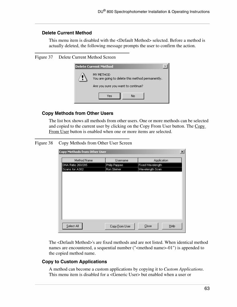
DU® 800 Spectrophotometer Installation & Operating Instructions
Delete Current Method
This menu item is disabled with the <Default Method> selected. Before a method is actually deleted, the following message prompts the user to confirm the action.
Figure 37 Delete Current Method Screen
Copy Methods from Other Users
The list box shows all methods from other users. One or more methods can be selected and copied to the current user by clicking on the Copy From User button. The Copy From User button is enabled when one or more items are selected.
Figure 38 Copy Methods from Other User Screen
The <Default Method>'s are fixed methods and are not listed. When identical method names are encountered, a sequential number ("<method name>-01") is appended to the copied method name.
Copy to Custom Applications
A method can become a custom applications by copying it to Custom Applications. This menu item is disabled for a <Generic User> but enabled when a user or
63
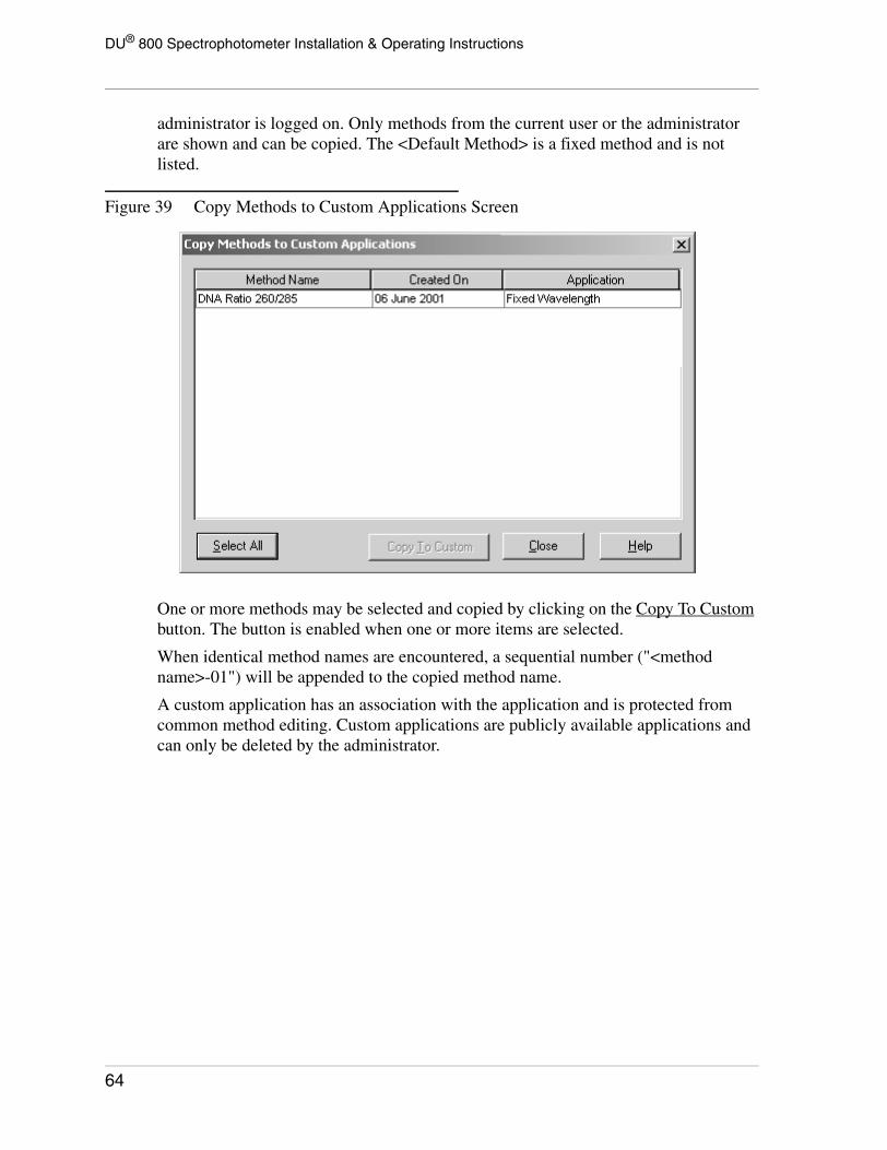
DU® 800 Spectrophotometer Installation & Operating Instructions
administrator is logged on. Only methods from the current user or the administrator are shown and can be copied. The <Default Method> is a fixed method and is not listed.
Figure 39 Copy Methods to Custom Applications Screen
One or more methods may be selected and copied by clicking on the Copy To Custom button. The button is enabled when one or more items are selected.
When identical method names are encountered, a sequential number ("<method name>-01") will be appended to the copied method name.
A custom application has an association with the application and is protected from common method editing. Custom applications are publicly available applications and can only be deleted by the administrator.
64

DU® 800 Spectrophotometer Installation & Operating Instructions
Backup/Export Methods
This function allows a user to backup one or multiple methods from the current user to a file. It can also be used to 'physically move' one or multiple methods from one instrument to another. The <Default Method> is a fixed method and is not listed.
Figure 40 Backup/Export Methods Screen
One or more methods may be selected and backed up by clicking on the Backup/Export button. The button is enabled when one or more items are selected.
Backup files have the extension ".bkx". The initial backup directory is the Backup Files folder in the DATA directory (e.g.; C:\DU800 Data\Steiner\Backup Files). It will be created automatically, if it does not already exist.
Restore/Import Methods
This function restores all or selected methods from a backup file. The initial backup directory is the Backup Files folder in the DATA directory (e.g.; C:\DU800 Data\Steiner\Backup Files). However, the user may browse and select a backup file from another location (e.g.; Drive A:).
65

DU® 800 Spectrophotometer Installation & Operating Instructions
Figure 41 Restore/Import Methods Screen
All methods in the backup file are shown and can be restored or imported. One or more methods may be selected and restored by clicking on the Restore/Import button, which is enabled when one or more items are selected.
The window features the Overwrite Existing Methods function. When this function is unchecked and an identical and existing method name is encountered, a sequential number ("<method name>-01") will be appended to the restored method name.
66

DU® 800 Spectrophotometer Installation & Operating Instructions
Tools Menu
Both, RediRead and RediScan provide an easy and fast way to take simple readings or scans. These modes act like "interrupt" programs that keep the workflow of the current application intact.
When a multi-position cell holder is used, the Cell Matching function can be used to correct for differences in the cell positions.
Generic User User Logon
Administrator Logon
67

DU® 800 Spectrophotometer Installation & Operating Instructions
To further process acquired data or obtain an independent, readable file, you may want to make it compatible with a commercial program using the Data Export function. The currently displayed data may be saved as a CSV (comma separated values) file that is compatible with commercial spreadsheet programs, such as Microsoft Excel.
Files may contain one or more Electronic Signature(s). The user may view the electronic signature(s) in a file that has been opened or add a signature to an existing DUX file, if he/she has the necessary privileges.
The User Options allow a logged-on user to set his/her preferences.
The Administration item is only enabled when the administrator is logged-on. The administrator has access to the following menu items:
• System Options• User Account Manager• Delete Custom Applications• System Audit Trail• Source Scheduler• Performance Validation Scheduler• Backup/Export System• Restore/Import System• Add Software Option(s)• Create Backup License File
RediRead
RediRead provides an easy and fast way to take readings at a fixed wavelength and provide a printed output. In this mode, the system will not store data or perform calculations. RediRead acts like an "interrupt" program that keeps the workflow of the current application intact.
The RediRead window is used to take single wavelength readings on one or more samples. The cell position of a multicell holder cannot be changed from within the program.
68

DU® 800 Spectrophotometer Installation & Operating Instructions
Figure 42 RediRead Screen
The read average time is fixed at 0.5 seconds. The user simply selects the appropriate read mode (Abs or %T) and wavelength.
Before taking a measurement, RediRead needs to be blanked on air or a blank solution. This is done by clicking on the Blank menu item or button. When a blank has been performed, the indicator BLANK REQUIRED will change to BLANKED and the user is ready to take measurements.
NOTICE
Because this mode is an independentprogram/module, the blank is owned by thismode and does not affect the blank of theapplication.
Trying to read a sample without a blank causes the following message to pop up. 'Yes' will read the sample without a blank.
69

DU® 800 Spectrophotometer Installation & Operating Instructions
Figure 43 RediRead Dialog Screen
The current wavelength and result are displayed in large characters, in addition to the grid. This makes it easy to walk up with a sample, take a measurement, read the result from the screen, and walk away.
The Read menu item or button takes a reading based on the selected read mode and wavelength. Clear will clear the grid, Print will print the content of the grid, and Close will close the window.
RediScan
RediScan provides an easy and fast way to take one or multiple wavelength scans and provide a printed output. In this mode, the system will not store data or perform calculations. RediScan acts like an "interrupt" program that keeps the workflow of the current application intact.
Up to six wavelength scans can be taken displayed in an overlay fashion. The cell position of a multicell holder cannot be changed from within the program. To avoid overlaying scans, simply click on the Clear menu item or button before taking the next scan.
70

DU® 800 Spectrophotometer Installation & Operating Instructions
Figure 44 RediScan Screen
The scan speed is fixed at 1200 nm/min, which represents readings at a 1.0 nm interval. The default scan mode is Abs and the default wavelength range is from 200.0 nm to 800.0 nm. Use the Set Scan Limits item in the Axis menu to modify the wavelength range over which the sample is scanned.
The system options set by the administrator act as default parameters for the y-axis, the grid and the legends.
Before taking a scan, RediScan needs to be blanked on air or a blank solution. This is done by clicking on the Blank menu item or button. When a blank has been performed, the indicator BLANK REQUIRED will change to BLANKED and the user is ready to take a scan.
NOTICE
Because this mode is an independentprogram/module, the blank is owned by thismode and does not affect the blank of theapplication.
Trying to take a scan without a blank causes the following message to pop up. 'Yes' will scan the sample without a blank.
71

DU® 800 Spectrophotometer Installation & Operating Instructions
Figure 45 Scan Without a Blank Dialog
The Scan menu item or button takes a wavelength scan based on the selected mode and wavelength range. Clear will clear the scan window, Print will print the current scan(s), and Close will close the window.
Function Menu
Trace
Trace is used to display the graphed data at the trace line position of the x-axis.
The menu item is disabled when there is no data. By default, the Trace function is inactive. When selected, the cursor in the scan window becomes a two-pointed horizontal arrow. As the trace line is moved across the screen using the mouse, the displayed values will be updated. In the case of curve fits, the actual data point values will be displayed when the trace line is near a data point.
Within the scan window, the left mouse button alternately removes and activates the trace line. In the active state, the cursor is limited to the scan window.
The data is shown in the respective color.
Trace is de-activated by selecting another function, such as Default (Off), Annotate or Zoom.
Annotate
The menu item is disabled when there is no data. By default, the Annotate function is inactive. When selected, the cursor in the graph window becomes an "A" character
72

DU® 800 Spectrophotometer Installation & Operating Instructions
with a small arrow terminating at the top left corner, which indicates where the hotspot is.
By clicking on a location within the graph window, a resizable box opens in which text can be entered. The text will be fixed to the location when Escape is pressed.
An existing annotation can be moved by holding down the Ctrl key and clicking on or near the text with the left mouse button. Releasing the mouse button will fix the annotation again.
Clicking on an existing annotation opens the annotation box and the annotation can be modified. The annotations and its locations are retained and saved with the scan. The number of annotations is not limited.
Annotate is de-activated by selecting another function, such as Default (Off), Trace or Zoom.
Zoom
The feature can be used to expand any portion of the graph.
The menu item is disabled when there is no data. When selected, the cursor in the scan window becomes a magnifying glass. To zoom in, click the left mouse button and drag the mouse to another location. When releasing the mouse button, the system zooms in onto the rectangle that has been drawn. The zoom can be repeated to zoom in further.
A double-click on the right mouse button will zoom out.
Zoom is de-activated by selecting another function, such as Default (Off), Trace or Annotate.
Grid
The default of this item is based on the system or user options setting. The grid can be turned on or off. This setting is temporary and will not be retained.
Within the annotation box, a right mouse click brings up a popup menu, which allows the user to fix, delete, or change the appearance of the annotation.
73

DU® 800 Spectrophotometer Installation & Operating Instructions
Axis Menu
Set Scan Limits
This item brings up a window, which allows the user to set both the x- and the y-axis parameters manually.
The Y-Axis limits are based on the current read mode. To modify the current wavelength range, change the X-Axis Limits.
Figure 46 Set Scan Limits Screen
When OK is clicked, the graph window will be refreshed.
Autoscale
The Autoscale X, Autoscale Y, and Autoscale Both items are enabled when data is available. These items automatically and immediately scale the respective axes.
Dynamic Autoscaling
This item is checked or unchecked depending on the system or user options setting. Dynamic autoscaling means that the y-axis will be re-scaled during data acquisition. The menu setting is temporary and will not be retained.
74

DU® 800 Spectrophotometer Installation & Operating Instructions
Read/Display Mode
The Abs and %T items indicate the current read mode by a check mark. When clicked, the scan(s) will be re-displayed immediately. The menu setting is temporary and will not be retained.
Cell Matching
When a multi-position cell holder is used, the Cell Matching function may be applied to correct for differences in the cells. Cell matching is performed using two or more cuvettes filled with a blank solution that are placed in a multi-position cell holder. The cell matching will be performed at the wavelength(s) selected. Up to three wavelengths can be used.
When the Match Cells button is pressed, the first cuvette is blanked and the value set to zero. Then, each following cuvette is measured and assigned a value relative to the first cuvette. These values are displayed in the grid as dAbs and d%T.
Figure 47 Cell Matching Screen
When the Use Cell Match box is checked, all readings taken by the instrument - in any application, except Wavelength Scan - will be corrected by the values displayed in the cell match window. This correction can be disabled and enabled without losing the correction values. The status bar indicates if the cell match correction is turned on or off.
75

DU® 800 Spectrophotometer Installation & Operating Instructions
NOTICE
When using cell match, make sure that thewavelength(s) are identical to thewavelength(s) of the application and that thecell match values are recent and from thesame cells in the same position and that thecells have not been removed.
For the most accurate correction, the cell match readings should be taken at the same wavelength(s) as in the subsequent application and the cuvettes should not be removed from the cell holder before the analysis. If the cuvettes are removed, it is necessary to return each to the same cell position in the same orientation for the correction to be valid.
Cell match correction is recommended when using the 6-Position Microcell Holder and the 12-Position Microcell Holder.
The column labels indicate the wavelength and the matching values in dAbs and d%T. The number of cells displayed and processed here is based on the current cell holder selection in the Accessories window. The maximum number of cells is 12.
The selection of a different number of wavelengths or the change of a wavelength will clear the grid and a new match has to be performed.
76

DU® 800 Spectrophotometer Installation & Operating Instructions
Data ExportThe Data Export item allows the user to save the currently displayed data as a CSV file. The CSV (Comma-Separated Values) format is a universal format and recognized by third party spreadsheet programs such as Microsoft Excel.
Figure 48 Example of Data Exported as a CSV File
The CSV file is recognized by compatible programs and will load the data automatically for further analysis. To create a CSV file, simply click on the Data Export function in the Tools menu and the curent data will be exported to a CSV file. The Data Export menu item is only available when data has been acquired or when a file has been loaded. Selecting this menu item will display a common File Save dialog.
The format of the CSV file follows these guidelines:
• Text information is embedding in quotes (to make sure intended commas are not interpreted as delimiters)
• All Header fields are text• All Labels are text
77

DU® 800 Spectrophotometer Installation & Operating Instructions
Example File
"Data Acquired:",,,"22 May 2000 03:50 PM""Company/Institute:",,,"Beckman Coulter, Inc." "Department:",,,"Bioresearch Development Center""Operator:",,,"Steiner""Comment:",,,"This is a note""Product Name:",,,"Abuprofin""Lot #:",,,"1234""Read Mode:",,,"Abs""Calculation Mode:",,,"Formula""Number of Wavelengths:",,,"2""#","Wavelength""1","250.0""2","300.0""Formula:",,,"wl350 / wl400.0 x 1000""Unit:",,,"ng/ml","250.0 nm","300.0 nm","Results""Sample ID","Abs","Abs","ng/ml" "My Sample ID #1",0.0374,0.0323,12.4939"Sample 2-1",0.0374,0.0323,9.4832
Electronic Signatures
21 CFR Part 11
By definition, data and result files (.DUX) that are created by the DU 800 Spectrophotometer are electronic records. Title 21 Code of Federal Regulations (21 CFR Part 11) Electronic Records; Electronic Signatures came into effect on 20 August 1997 and sets forth criteria under which the agency considers electronic records, electronic signatures, and handwritten signatures executed to electronic records to be trustworthy, reliable, and generally equivalent to paper records and handwritten signatures executed on paper. People using electronic signatures must certify to the agency that the electronic signatures in their system are intended to be the legally binding equivalent of traditional handwritten signatures.
For more information, please refer to:
Code of Federal Regulations
Title 21, Part 11: Electronic Records; Electronic Signatures
U.S. Government Printing Office
http://www.access.gpo.gov/nara/cfr/cfr-retrieve.html#page1
(CITE: 21CFR11.1)
View Electronic Signature(s)
This item is enabled when a file has been opened and when an electronic signature exists in the file. The function calls a window that displays the Signer’s Name and Role (Author, Reviewer, or Approver), the Date/Time of the signature, and a Note or Annotation (if one exists). All signatures included in the file will be displayed. A file may contain up to five signatures.
78

DU® 800 Spectrophotometer Installation & Operating Instructions
Figure 49 Electronic Signature Authentication Screen
Add Electronic Signature
The Electronic Signature consists of encrypted information based on the user name, and password as well as the serial number of the instrument. In addition to the signature, the file also includes:
• Name of the Signer (in readable form)• Date and Time of the Signature• Role of Signer (Author, Reviewer, or Approver)• Note (empty by default)
79

DU® 800 Spectrophotometer Installation & Operating Instructions
Once added, the Electronic Signature will become a fixed part of the DUX file.
Figure 50 Add Electronic Signature Screen
The Add Electronic Signature menu item will give a logged-on user or the administrator the ability to sign a file. The menu item is only enabled when a file has been opened and if the user has a Signature Privilege, which is assigned by the Administrator in the User Account Manager screen. Before a signature can be added, the user will be prompted to repeat the logon. The signature is added to the existing file immediately. The file does not need to be saved to add the signature.
Existing DUX files cannot be overwritten. Trying to save a file under the same name will prompt the user to specify a new filename. If the user saves data under a new filename, all existing signatures will be removed.
A user or the administrator may sign a file as an Author, Reviewer, or Approver, depending on the available signature privilege. Only one Author is allowed per file. If an Author already exists, the Author button will be disabled. Multiple Reviewers and Approvers are permitted. When attempting to add a signature twice, e.g., same user in a different role, the user will be prompted. A file can include a maximum of five signatures.
The Note field allows the user to add an annotation.
User OptionsThis item is only visible when a user is logged on and disabled with a <Generic User> and the administrator. The function calls a window and lets the user set his/her preferences. Many user parameters are identical to the system parameters.
The default settings for user parameters are the system parameters. User preferences have priority over system parameters and are used in place of the system parameters. The parameters that are applied to the <Generic User> are the system parameters.
80

DU® 800 Spectrophotometer Installation & Operating Instructions
Output Tab
The Output tab includes the preferences for the screen and printer outputs. The content is identical to System Options, Output Tab.
Header Tab
The Header tab includes the custom header information and the selection for the length of the application header. This tab includes the Department and the Operator fields. Although, the content is different from the System Options tab of the same name, which has the system-wide Organization field, both tabs serve the same purpose (see System Options, Header Tab).
Graph Tab
The Graph tab includes the preferences for the graph window. The content is identical to System Options, Graph Tab.
Colors Tab
The Colors tab includes the color preferences for the graph window. The content is identical to System Options, Colors Tab.
AdministrationThe Administration item is only enabled when an administrator is logged on. Other users have no access to the functions included in this sub menu.
The following administrator functions are accessible through the Administration menu:
System Options
User Account Manager
Delete Custom Applications
System Audit Trail
Source Scheduler
Performance Validation Scheduler
Backup/Export System
Restore/Import System
Add Software Option(s)
Create Backup License File
81

DU® 800 Spectrophotometer Installation & Operating Instructions
NOTICE
Be aware that the Administrator and theUser logon of the DU 800 are entirelyindependent of the Microsoft WindowsOperating System logon.
System OptionsIn general, System Options apply to the <Generic User> and the Administrator. Many of these parameters serve also as default preferences for Users.
Setup Tab
The Setup tab determines the path of the user directory. In addition, it allows the administrator to determine timeout functions. This tab does not exist in the User Options.
Figure 51 System Options Screen with Setup Tab Selected
The information in the Administrator field will be used in message boxes that refer to the administrator. We recommend to enter the administrator's name. With an empty field, the text "Administrator" will be used.
Data files will be stored and accessed in the DATA Root, which is easily accessible through the Windows Explorer. The default directory is "C:\DU800 Data" and may be changed by the administrator. Instead of a fixed path, a UNC (Universal Naming Convention) path may be entered or selected.
When defining a new DATA root directory (complete path), the directory will be created automatically, if it does not already exist. Both, a local directory and an UNC
82

DU® 800 Spectrophotometer Installation & Operating Instructions
(Universal Naming Convention) path will be accepted. The Default button resets the parameters of this tab.
NOTICE
When defining a DATA root on a networkdrive, make sure that the required accessprivileges are available.
Instead of entering the path for the DATA root directory, you may browse for an existing directory by clicking on the Browse button to the right of the text field.
By default, the Idle Timeout Functions are unchecked.
The Automatic Logoff is required for 21 CFR Part 11 and will automatically log off the current user and return to the <Generic User> level when the system is idle for more than the specified time. When a user is logged on and the system is in an “open run” (e.g., it is busy with a Kinetics run), instead of logging off, the system continues the Kinetics run and displays a protected DU 800 screen saver.
The DU 800 screen saver is automatically selected whenever the DU 800 software is running and Automatic Logoff is selected. When the software is exited, the system will return to the previously selected screen saver. The DU 800 screen saver will lock the computer until the current user or the administrator enters his/her password.
Figure 52 User Authentication Screen
The Elapsed Time list box contains pre-defined entries: 1, 2, 5, 10, 20, 30 minutes and 1 or 2 hours. The default is 10.0 minutes.
83

DU® 800 Spectrophotometer Installation & Operating Instructions
If checked, the UV Lamp Shutoff and the Visible Lamp Shutoff items turn the respective lamps off when the system is idle for more that the specified time (idle means that no measurement has bee taken for a while).
The respective lamp will not be turned off when the systm is in an “open run” or a file has been opened. Also, the Source Scheduler has priority over the UV Lamp Shutoff and the Visible Lamp Shutoff functions.
Specifiy the Elapsed Time that should apply to the Automatic Logoff and the Lamp Shutoff functions.
Output Tab
The Output tab includes the preferences for the screen and printer outputs.
Figure 53 User Options Screen with Output Tab Selected
The default settings for the screen are MS Sans Serif, 8 pts and for the printer Courier New, 10 pts. The Change Font buttons call the Windows Dialog function for the selection of fonts.
NOTICE
A very small or large font size may notcreate the desirable output. In this case, youmay consider going back to the defaultsettings. The printouts are optimized for thedefault settings.
It is important to notice that the Screen Font Characteristics are only effective for the SCAN GRAPH and the DATA GRID areas - no other parts of the software are affected.
84

DU® 800 Spectrophotometer Installation & Operating Instructions
The # of Decimal Points determine the reported precision of the Abs and %T readings. The defaults are four (4) for Abs and one (1) for %T.
The Highlight Results option is unchecked by default. Initially, the Color Preference is set to "pink" and Bold is unchecked. The color is selected by calling the standard Windows Dialog function for the selection of colors. This option only applies to the RESULT column(s) in the DATA GRID areas and the printout.
The Default button resets the parameters of this tab.
Headers Tab
The Header tab includes the custom header information and the selection for the length of the application header. Headers apply to printouts and files.
Figure 54 User Options Screen with Headers Tab Selected
The Organization and Department fields are text fields. The information entered in the Organization field is applied system-wide. The department information serves as the default for the User Options and will be applied to the <Generic User> printout header.
Additional header information can be defined for each application (see Methods, Report Tab).
The Application Header allows the administrator or user to set the length of the application header for the printout. There are three priority levels, which are predefined.
85

DU® 800 Spectrophotometer Installation & Operating Instructions
Graph Tab
The Graph tab includes the preferences for the graph window.
Figure 55 User Options Screen with Graph Tab Selected
The Grid option turns the grid on or off. By default, this option is checked.
The Symbols option turns the symbols for data points on or off. By default, this option is checked.
The Emphasize Selected Scan option emphasizes the scan in focus with a bold line. By default, this option is checked.
The Dynamic Autoscaling option determines if dynamic autoscaling during data acquisition is performed or not. By default, this option is checked.
The Y-Axis Default values may be modified. The default values are: 0.0 to 3.0 for Abs (input range is -0.3 to 4.5) and 0 to 100 for %T (input range is 0 to 200).
The 3-D Offset frame includes the selection for the data shift to accomplish a 3-dimensional look for overlayed scans. The axis values apply to the first scan only. All other scans are shifted and the axis values cannot be applied. The default is 'Medium'.
The Default button resets the parameters of this tab.
86

DU® 800 Spectrophotometer Installation & Operating Instructions
Colors Tab
The Colors tab includes the color preferences for the graph window.
Figure 56 User Options Screen with Colors Tab Selected
This tab specifies the Graph Colors for both the screen and the printer. The colors are selected by clicking on the colored box. This evokes the Windows Dialog function for the selection of colors.
The items in the Graph Colors frame include the settings for the Window Background, the Graph Background, and the Grid.
The items in the Scan Colors frame determine the color of the individual scans.
The Default button resets the preferences of this tab.
87

DU® 800 Spectrophotometer Installation & Operating Instructions
Regulatory Tab
The parameters in the Regulatory tab also apply to Title 21 Code of Federal Regulations (21 CFR Part 11) Electronic Records; Electronic Signatures.
Figure 57 System Options Screen with Regulatory Tab Selected
The Electronic Signature feature is unchecked by default. When checked, it allows authorized users to add and an electronic signature to a data or results file. The signature itself is based on the logon as well as other information and is unique (see section Electronic Signature for more information).
In order to restrict the use of the system to logged-on users and prevent unauthorized access, the No <Generic User> Access feature must be checked.
With the Password Renewal feature checked, the user and the administration passwords needs to be renewed after a given time period. By default, this feature is disabled. When the feature has been enabled and the renewal time exceeded, the user must change his/her password in order to complete the logon process. The default renewal time is 90 days. The administrator may change this parameter when the feature is enabled. The entry is limited to 10-365 days.
88

DU® 800 Spectrophotometer Installation & Operating Instructions
The following message appears at logon, if the password requires renewal.
Figure 58 Password Renewal Screen
When continuing, the Password Renewal window lets the user update the current password. 'No' in the above message box or 'Cancel' from the Password Renewal window will abort the logon.
With the System Audit Trail feature checked, key events will be logged to an audit trail file. By default, this feature is disabled. This feature records all major events as indicated by the check boxes.
The following actions will be recorded, if checked:
a. User Logon, including failed attempts, and User Logoff.b. Password change.c. Start and end of data acquisition (open run - start to clear).d. Loading and saving of a file.e. Saving methods (created or modifed).f. Deleting methods.g. Copying methods (from another user or to custom applications).h. Backing up and restoring methods.i. Adding and deleting user accounts
The file has the fixed name “DU 800 Audit Trail.log” and is a protected file. The “master” System Audit Trail file is kept in the “Audit Trail” directory, located in the INSTALL directory. A “slave” System Audit Trail is maintained in the DATA directory to facilitate data archiving. This “slave” file is automatically updated each time a DU 800 data file is saved.
To keep the file at a manageable size, the operator will be prompted to inform the Administrator that the System Audit Trail requires maintenance. The message appears when the entered backup time of file size has been exceeded, whichever comes first. The range for the backup time is 0 to 2000 days and the range for the file size is 64 to 2048 Kbytes.
89

DU® 800 Spectrophotometer Installation & Operating Instructions
User Account ManagerThe User Account Manager allows the administrator to add or delete user accounts and provide the initial password to an account.
Figure 59 User Account Manager Screen
The administrator is able to create (Add) and Delete user accounts. A user requires a password, which is initially given by the administrator. From this point on, the user is able to change his or her password at any time. The Change Password button allows the administrator to change the password of an existing user.
For each user, one or more Electronic Signature Privileges can be assigned. The default is 'Author'. The privileges include: 'Author', 'Reviewer', and 'Approver'. For more information on Electronic Signatures, refer to Electronic Signature(s).
The minimum number of characters for both user name and password is 4. The maximum length is 32 for the user name and 12 for the password. The current users are shown in a list box. To change a user's password or to delete the account, select the respective user name first.
To create a user account, simply enter the new user name and click on the Add button. The Create Password window pops up, which lets you enter the initial password. Enter a password and click on OK to return to the User Account Manager. You may then continue to add user accounts or close the window.
To delete a user account, select the appropriate user name in the list box and click on the Delete button. The user name will be removed from the list and the account deleted. The methods and data files for this user account will not be deleted.
90

DU® 800 Spectrophotometer Installation & Operating Instructions
Delete Custom ApplicationsThe Delete Custom Applications menu item allows the administrator to remove custom applications. The menu item is disabled when a custom applications is selected. To perform this function, a regular application must be selected.
The list box displays the current custom applications and lets the administrator select one or multiple methods with the usual Windows key combinations.
Figure 60 Delete Custom Applications Screen
Initially, the Delete button is disabled. It will be enabled when one or more items are selected. The deleted custom applications are removed permanently.
91

DU® 800 Spectrophotometer Installation & Operating Instructions
View System Audit TrailThe System Audit Trail menu item opens a new window and displays the content of the active audit trail file or a selected audit trail file. The file may be printed or backed up.
Figure 61 System Audit Trail Screen
When the Backup button is selected, the entire active audit trail is automatically saved in the “Audit Trail” directory, located in the INSTALL directory. A copy of this backup file is also created in the DATA directory.
With the System Audit Trail successfully backed up, the software will begin recording a new audit trail. The entries of the last two weeks will be retrieved to provide overlap and continuity.
92

DU® 800 Spectrophotometer Installation & Operating Instructions
Source SchedulerThe Source Scheduler allows the administrator to turn both sources on and off individually at a scheduled time for specified days.
Figure 62 Source Scheduler Screen
The default settings are shown in the above screen.
The Source Scheduler will not work when the system is in an “open run” or when a file has been opened.
The On and Off times can be set to OFF or from 5:00 AM to 10:00 PM for each day. The times are in ½ hour intervals and the format is based on the international setting of Windows.
The Use check box provides a quick way to turn the scheduler on or off for a particular day without changing the previously selected times. By default, these boxes are unchecked.
The Default button resets the preferences of the Source Scheduler.
93

DU® 800 Spectrophotometer Installation & Operating Instructions
Performance Validation SchedulerThe Performance Validation Scheduler allows the administrator to automatically execute one or more Performance Validation programs at a given day and time.
Figure 63 Performance Validation Scheduler Screen
The Start Time can be turned OFF or selected in the drop-down list box for each day. The times are from 5:00 AM to 10:00 PM in ½ hour intervals. The time format is based on the international setting of Windows.
The Performance Validation Scheduler will not execute the selected test(s) when the system is in an “open run” or a file has been opened.
The Program or Group selections for the Performance Validation programs are:
a. Noneb. Run Group [1] Tests (3 min 30 sec)c. Run All Tests (1 hour 4 min)d. [1] Wavelength Drive Test (24 sec)e. [1] Resolution Test (12 sec)f. [1] Baseline Flatness Test (1 min 40 sec)g. [1] Noise Test (1 min)h. [2] Stability Test (60 min)
BOTH THE VISIBLE AND THE UV LAMPS ARE REQUIRED FOR THE PERFORMANCE VALIDATION SCHEDULER.
THE SYSTEM WILL MAKE SURE THAT BOTH LAMPS ARE TURNED ON FOR THE TEST(S).
94

DU® 800 Spectrophotometer Installation & Operating Instructions
In order to receive accurate results, it is recommended that both lamps are warmed up (UV lamp requires one hour) prior to running Performance Validation tests. If either lamp is off at the scheduled time, the Performance Validation Scheduler will turn on both lamps and wait one hour before executing the selected test(s).
The Source Scheduler can be used to automatically turn on the lamps one hour before the Start Time selected in the Performance Validation Scheduler and to turn off the lamps at appropriate time (e.g., at the end of a work day).
After the selected Performance Validation program(s) have been completed, the results may be printed and saved automatically. By default, Print and Save are checked. If Save is checked, the results will be saved to a file. The filename is based on the Results File Prefix. The date of the test(s) will be appended to the filename prefix automatically in the following format: "<file prefix> YYMMDDHHMMSS.txt". The location for the file is the "Performance Validation" directory in the DATA root directory.
When the Performance Validation Scheduler activates, the following message is displayed:
Figure 64 Performance Validation Schedules Activation Dialog
When all tests are within specifications, the following message appears:
Figure 65 Performance Validation Scheduler Screen
95
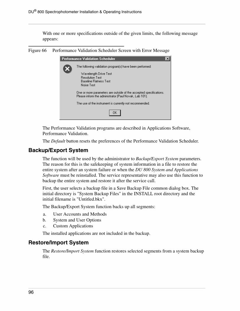
DU® 800 Spectrophotometer Installation & Operating Instructions
With one or more specifications outside of the given limits, the following message appears:
Figure 66 Performance Validation Scheduler Screen with Error Message
The Performance Validation programs are described in Applications Software, Performance Validation.
The Default button resets the preferences of the Performance Validation Scheduler.
Backup/Export SystemThe function will be used by the administrator to Backup/Export System parameters. The reason for this is the safekeeping of system information in a file to restore the entire system after an system failure or when the DU 800 System and Applications Software must be reinstalled. The service representative may also use this function to backup the entire system and restore it after the service call.
First, the user selects a backup file in a Save Backup File common dialog box. The initial directory is "System Backup Files" in the INSTALL root directory and the initial filename is "Untitled.bkx".
The Backup/Export System function backs up all segments:
a. User Accounts and Methodsb. System and User Optionsc. Custom Applications
The installed applications are not included in the backup.
Restore/Import SystemThe Restore/Import System function restores selected segments from a system backup file.
96

DU® 800 Spectrophotometer Installation & Operating Instructions
First, the administrator selects a backup file in an Open Backup File dialog box. The initial directory is "System Backup Files" in the INSTALL root directory.
Figure 67 Restore/Import System Screen
By default, the Overwrite options are unchecked.
The following rules apply for restoring information:
1. Users Accounts and Methods
Non-existing user accounts: Users will be added with all passwords, methods, and user options retained.
Existing user accounts: With the Overwrite option unchecked, only non-existing methods will be restored. With the Overwrite option checked, all existing passwords, methods and user options will be replaced.
2. System Options
The system options will be restored and overwritten.
3. Custom Applications
With the Overwrite option unchecked, only non-existing custom applications will be restored. With the Overwrite option checked, all existing custom applications will be replaced.
97

DU® 800 Spectrophotometer Installation & Operating Instructions
Add Software Option(s)The Add Software Option(s) function allows the administrator to install one or more software options.
Figure 68 Add Software Options(s) Screen
The license is initially provided on a floppy disk and is usually installed from there.
Figure 69 Select License File Screen
A dialog box will show the available license files on the selected medium. No other file types will be shown. The application(s) that are included in the selected license file will be displayed.
98

DU® 800 Spectrophotometer Installation & Operating Instructions
Figure 70 Add Software Options(s) Screen
Click on 'Yes' to install the software option(s). Installed software options cannot be removed. If the system encounters a file without a valid license, it will inform the user via a message box that this an invalid license.
When the DU 800 System and Appplications Software has been installed on a computer, which is not connected to a DU 800 Spectrophotometer, software options can be installed from the floppy disk that includes the license. However, it is important to notice that the software option must first be added to a computer with the DU 800 Spectrophotometer connected.
A T T E N T I O N
Licenses for software options are providedon a floppy disk.
It is recommended to Create a BackupLicense File after one or more softwareoptions have been added. Make sure tostore the file in a safe location.
Create Backup License FileThe Create Backup License File function creates a backup file that includes all licenses for the currently installed software options. This function is recommended and should be performed after all software options have been added.
A T T E N T I O N
Create a Backup License File after thesoftware option(s) have been added.
MAKE SURE TO STORE THE BACKUPFILE IN A SAFE LOCATION.
99

DU® 800 Spectrophotometer Installation & Operating Instructions
In the case of an emergency, or if the software is re-installed on another computer, the backup license file allows you to restore the licenses for the purchased software options.
Diagnostic Menu
The Diagnostic functions consist of two parts. The System Status and the User Diagnostics windows are accessible by any user and are described below. The Service Diagnostics functions are reserved for service personnel and can only be accessed through a specific password.
System Status
This window displays common information about the spectrophotometer and the operating system.
When the lamp time approaches 100% of the typical life expectancy, the administrator might consider replacing the respective lamp in order to avoid interruption when the lamp actually burns out.
The Print button outputs the information displayed in this window. The Computer Info button calls a separate Microsoft program which provides detailed information about the computer.
100

DU® 800 Spectrophotometer Installation & Operating Instructions
Figure 71 System Status Screen
User Diagnostics
Calibrate Wavelength
This function is used to calibrate the wavelength drive, if the wavelength accuracy is not within the expected range. The wavelength accuracy can be tested with the Performance Validation program.
Figure 72 Wavelength Calibration Screen
Performing a wavelength calibration takes approximately 2 minutes. The message "Wavelength calibration in progress ..." flashes during that time. When it is finished, the message reads "Wavelength calibration finished".
101

DU® 800 Spectrophotometer Installation & Operating Instructions
Run Baseline Test
The functionality of the Baseline Flatness Test takes a blank reading on air, followed by a sample scan on air to test the flatness of the baseline from 200 to 900 nm.
Figure 73 Baseline Test Screen
To test the baseline flatness, follow these steps:
1. Verify that both sources are turned on and that they have stabilized for at least one hour.
2. Verify that nothing is in the sample compartment that can potentially block or disturb the light beam.
3. Click on the Scan Baseline button or the respective menu item. The instrument automatically performs the test, displays the baseline and calculates the RMS Flatness. The expected RMS Flatness should be less than 0.001A.
4. You may click on the Print button or the respective menu item to print the baseline.
Set Scan Gains
The scan gains are set at the factory prior to shipment. The gains are checked and adjusted each time that the wavelength drive is calibrated, as described earlier. When a wavelength scan is performed using a blank that has significant absorbance in the
102

DU® 800 Spectrophotometer Installation & Operating Instructions
scanning range, it may be desirable to change the gain settings in the instrument to compensate for the absorbance of the blank. This will increase the dynamic range of the instrument when scanning using the absorbance blank.
Figure 74 Set Scan Gains Screen
To change the scan gains, follow these steps.
1. Verify that both sources are turned on and that they have stabilized for at least one hour.
2. Place a cuvette containing blank solution in the cell holder.
3. Click on the Set Scan Gains Now button. The instrument adjusts the scan gain values to compensate for the absorbance of the blank.
NOTICE
The instrument will continue to use the newgain values until the gain is adjusted usingeither the Calibrate Wavelength or the SetScan Gains function. It may be desirable torepeat the above procedure with nothing inthe sample compartment after changing thegain for a significantly absorbing blank.
103

DU® 800 Spectrophotometer Installation & Operating Instructions
Reset Source Hours
This function resets the internal usage counter for both, the Visible Source and the UV Source. Click on Reset Hours for Visible Source or Reset Hours for UV Source to reset the counter.
Figure 75 Reset Source Hours Screen
A message will prompt the user to confirm the action or abort.
NOTICE
Do not reset the usage counter unless therespective source has been replaced.Valuable service information will be lostotherwise.
104

DU® 800 Spectrophotometer Installation & Operating Instructions
Service DiagnosticsThe Service Diagnostic function is password protected and will only be accessed by service personnel and manufacturing.
Figure 76 Service Diagnostics Screens
The first window is the default. When clicking on Change Password, the window will be enlarged to allow the operator to enter and confirm a new password. Three attempts to enter the correct password are allowed. These passwords are not case-sensitive.
Calibration Info
More information about this function is available in the DU 800 Service Manual.
Figure 77 Calibration Information Screen
105

DU® 800 Spectrophotometer Installation & Operating Instructions
Wavelength Drive Run
More information about this function is available in the DU 800 Service Manual.
Figure 78 Wavelength Drive Run Screen
"Current Cycle = X" will be displayed during a run and then replaced by "Finished Run".
106

DU® 800 Spectrophotometer Installation & Operating Instructions
DRP Scan
More information about this function is available in the DU 800 Service Manual.
Figure 79 DRP Scan Screen
The DRP scan window is very similar to the 'Baseline' or 'Run Baseline Test' window.
The Commands menu items perform the same functions as the buttons. The Axis menu items are described in RediScan.
The default Wavelength parameters are 190.0 nm and 1100.nm (range from 190.0 nm to 1100.0 mm). The default Counts parameters are 0 to 50,000 (range is from 0 to 50,000)
The Blank scan is taken automatically before the actual DRP scan.
The scan can be printed but not saved to a file.
107

DU® 800 Spectrophotometer Installation & Operating Instructions
Blocked Beam Noise
More information about this function is available in the DU 800 Service Manual.
Figure 80 Blocked Beam Noise Screen
Erase EEPROM
More information about this function is available in the DU 800 Service Manual.
Figure 81 Erase EEPROM Attention Message Screen
108

DU® 800 Spectrophotometer Installation & Operating Instructions
Help Menu
The first three sections of this menu allow the user to access the help file in different ways. The Contents item calls the "List of Topics" and lets you go to a specific item systematically. The Search by Index item lets you search for a specific item by index.
The System Software, Applications Software, and Support and Service items will bring you right to the top level of the respective section.
The Installation and Getting Started items should be accessed when installing the system and to introduce a user to the basic functionality, using three examples. The Accessories item gets you right to the appropriate accessory section.
The Adobe Acrobat Files (PDF) item calls the Adobe Acrobat Reader and automatically loads the respective Installation and Operating Instructions or other documentation. The respective PDF files will be copied to the hard disk during the installation process to make the information readily available.
Adobe Acrobat might have been installed during the DU 800 System and Applications Software installation. However, the installation of Adobe Acrobat during installation is
109

DU® 800 Spectrophotometer Installation & Operating Instructions
optional. If a valid Adobe Acrobat installation cannot be found, an error message appears. In this case, you might want to install or re-install Adobe Acrobat.
Figure 82 About This Program Screen
The About this Program item provides program, version and copyright information.
Applications SoftwareThe applications software is described in Help and the optional Software Reference Manual.
110

DU® 800 Spectrophotometer Installation & Operating Instructions
Sampling Accessories
TransportAmbient or water temperature-controlled Single Cell Holders can be installed on the Static Mount and do not require a transport. However, they may also be mounted on the transport. Multi-Position Cell Holders require a transport.
Figure 83 Transport Accessory
Two types of transports are available:
• Standard Transport
For ambient and water temperature-controlled cell holders and all types of cuvettes.
• High Performance Transport
Required for Peltier temperature-controlled cell holders. This transport contains a fan to remove excess heat and provides additional accuracy in positioning microcells.
Refer also to the Installation Instructions, Transport Accessory (P/N 512870).
A901288P.AI
111

DU® 800 Spectrophotometer Installation & Operating Instructions
Cell HoldersThe installed cell holder must be specified by the user in the Transport/Holders tab of the Accessories window. All available cell holders from Beckman Coulter can be configured as well as a custom cell holder with up to 12 positions.
Figure 84 Cell Holders
The following cell holders are available:
• Single Cell Holders- Ambient (adjustable)- Water-temperature controlled- Peltier-temperature controlled*
• Single Cell Holder, Rectangular, Ambient• Single Cell Holder, Cylindrical, Ambient• Turbidity Cell Holder (Single), Ambient• 6-Position Cell Holder
- Ambient- Water-temperature controlled- Peltier-temperature controlled*
• 6-Position Microcell Holder, Ambient• 7-Position Cell Holder, Ambient• 8-Position Cell Holder, Ambient• 12-Position Microcell Holder, Ambient• Tm Microcell Holder, Peltier-temperature controlled**
* These cell holders require a Peltier Temperature Controller and the High Performance Transport to remove the excess heat.
** This cell holder requires the High-Performance Peltier Temperature Controller and the High Performance Transport to remove the excess heat.
Refer also to the Installation Instructions, Single Cell Holders (P/N 512874) and Installation Instructions, Multicell Holders (P/N 512875).
A901285P.AI
112

DU® 800 Spectrophotometer Installation & Operating Instructions
Sipper AccessoryThe sipper consists of a peristaltic pump, which is used to aspirate a sample into a flow cell. After the sample is aspirated into the flow cell, a reading is taken automatically.
Figure 85 Sipper Accessory
The Sipper Installed item in the Sipper tab of the Accessories window must be checked when a sipper is installed. The sipper parameters are in the same tab and may be optimized for the samples.
Refer also to the Installation Instructions, Sipper Accessory (P/N 512873).
Sipper Controls
The sipper panel has four control buttons.
[FILL/BLANK] - Aspirates the sample for the set Fill Time, waits the set Read Delay Time, and then reads the sample as a blank.
[RETURN] - Returns the sample for the set Return Time.
[FLUSH] - Runs the pump in the forward direction as long as the button is pressed. Used to flush the flow cell with solvent, sample, etc. without taking a subsequent measurement. After flushing the flow cell with solution, the user may take a reading as an alternative to [FILL/READ].
[FILL/READ] - Aspirates the sample for the set Fill Time, waits the set Read Delay Time, and then reads the sample as a sample.
[RETURN], [FILL/BLANK] and [FLUSH] are active at all times. [FILL/READ] is only active when "Sipper" and/or "Batch Sampler" are selected in the Sampler tab of the Method window.
A901287P.AI
113

DU® 800 Spectrophotometer Installation & Operating Instructions
Sipper Operation
1. Verify that the desired fill time, return time, read delay time, and sipper speed have been set.
2. Clean the flow cell by flushing with distilled water, then an alkaline solution, distilled water again, and finally the solvent used for the analysis. Several seconds with each solution should be sufficient for cleaning, if the flow cell was cleaned after the previous use.
3. Make sure that Sipper is selected in the Sampler tab of the Method window.
4. Blank - Aspirate the blank using [FILL/BLANK]. This will blank the system.
5. Flush the solvent from the flow cell using [FLUSH] or return the solvent using [RETURN]. It is important to have at least a 5 second air flush between each sample to minimize carryover.
6. Analyses requiring a re-read of standards only. Aspirate the standard using [FILL/READ]. Then put the focus onto the desired Standard and Replicate by clicking on the respective row in the grid below the standard curve. Flush or return each sample.
7. Samples - If desired, change the default sample identification (Sample n) to a meaningful description. Aspirate and read each sample using [FILL/READ]. Flush or return after each sample.
8. When the analysis is complete, clean the flow cell using solvent, then an alkaline solution, and distilled water. When the flow cell is clean, leave it filled with distilled water. It is important that the flow cell never be left to air dry.
9. At the end of the day, the daily cleaning procedure described in the Section Cleaning of Flow Cells in the Installation Instructions, Single Cell Holders (P/N 512874) and Installation Instructions, Multicell Holders (P/N 512875) should be used. Shortcuts in the cleaning procedure usually prove to be self-defeating and should be avoided since a build up of contaminants may occur. The tubing should remain attached to the flow cell. When use is resumed, the flow cell need only be emptied, flushed several times, then filled with sample.
114

DU® 800 Spectrophotometer Installation & Operating Instructions
Batch Sampler AccessoryThe batch sampler is an autosampler capable of holding multiple samples in test tubes. The solutions held in the test tubes are aspirated into the sipper flow cell for analysis, using the sipper pump. After the analysis, the samples either are returned to the batch sampler or are sent to waste. If the batch sampler has a wash station, the flow cell can be rinsed between samples.
Figure 86 Batch Sampler Accessroy
The batch sampler offered by Beckman Coulter is capable of holding up to 114 samples. Currently, this is the only batch sampler that is supported by the software.
NOTICE
The sipper accessory is required.
The batch sampler must be selected in the Batch Sampler tab of the Accessories window for proper operation. The fill time, return time, read delay time, and the sipper speed parameters in the same tab might be optimized for the samples. The recommended minimum sample volume with the batch sampler is 1.5 mL.
Refer also to the Installation Instructions, Batch Sampler Accessory (P/N 512871).
Beckman Coulter (ISCO) Batch Sampler
Stop Rack - The batch sampler is provided with 18 white test tube racks and 1 red (stop) rack. The stop rack is sensed by the batch sampler. When the last sample position of the stop rack is reached, the analysis will stop, even if there are more samples to read.
A901284P.AI
115
DU® 800 Spectrophotometer Installation & Operating Instructions
Manual Advance Button - This button is located on the back of the batch sampler and will raise the aspirator arm, if it is lowered, and advance the racks one sample position.
Manual Movement of the Aspirator Arm - The aspirator arm can be moved manually up and down, to and from the wash station (if installed), and to the next tube position. To move it, click on the respective button in the Batch Sampler tab.
Automatic Operation
1. If the batch sampler aspirator tube is positioned above the last position in the red stop rack, press the Manual Advance button on the back of the batch sampler to advance the racks one sample position.
2. Clean the flow cell by flushing with distilled water, then an alkaline solution, distilled water again, and finally the solvent used for the analysis. Several seconds with each solution should be sufficient for cleaning, if the flow cell was cleaned after the previous use. Empty the flow cell by pressing [FLUSH] for about 5 seconds.
3. Make sure that Batch Sampler is selected in the Sampler tab of the Method window.
4. Place all solution in 13 x 100 mm test tubes.
5. Blank - Place the blank directly under the aspirator tube. Click on the Lower Arm button to lower the aspirator arm.
Press [FLUSH] until the blank solution is aspirated into the flow cell and blank the system. Then press [FLUSH] to aspirate the solution to waste. Raise the aspirator arm by clicking on the Raise Arm button.
6. Analyses with standards only. Place the standard(s) in order, starting with the tube directly under the aspirator tube. Click on the GO icon. The batch sampler will aspirate each standard, read it, return it as specified, and move to the next position. Standard readings are taken until either the last standard is read or the last position of the red stop rack is read.
7. Samples - Place the samples in the tubes, starting with the tube directly under the aspirator tube. Do not leave any empty positions. Click on the START icon. The samples are analyzed. The default sample identifications will be applied (Sample n), where n is a sequential number starting with 1.
8. The analysis will terminate when the sample in the last position of the red stop rack has been read.
9. When the analysis is complete, clean the flow cell using solvent, then an alkaline solution, and distilled water. When the flow cell is clean, leave it filled with distilled water. It is important that the flow cell never be left to air dry.
10. At the end of the day, the daily cleaning procedure described in the Section Cleaning of Flow Cells in the Installation Instructions, Single Cell Holders (P/N 512874) and Installation Instructions, Multicell Holders (P/N 512875) should be used. Shortcuts in the cleaning procedure usually prove to be self-defeating and
116

DU® 800 Spectrophotometer Installation & Operating Instructions
should be avoided since a build up of contaminants may occur. The tubing should remain attached to the flow cell. When use is resumed, the flow cell need only be emptied, flushed several times, then filled with sample.
Manual Operation
It is sometimes desirable or necessary to place samples in the batch sampler and manually aspirate them into the instrument for readings, rather than analyzing them automatically.
Examples of situations where this may occur are:
1. Blanking before an automatic analysis.
2. After automatic analysis of standards, when one or more standards need to be re-run.
3. When the batch sampler is set up and used for a routine assay. Between assays, a wavelength scan needs to be taken on a sample.
To perform these analyses:
1. Verify that the desired operating parameters are set. In the third example above, the RediScan mode can be used.
2. Place the sample in the batch sampler under the aspirator arm.
3. Click on the Lower Arm button to lower the aspirator arm.
4. Press [FLUSH] until the flow cell is filled to aspirate the solution manually.
5. Blank or take a reading.
6. After the reading is taken, press [FLUSH] to aspirate the solution to waste.
7. To read another solution, located in the next position in the batch sampler, click on the appropriate button to raise the aspirator arm, advance to the next sample, and lower the arm again. Repeat the directions in steps 4 to 6 to take another reading.
Peltier Temperature Controller
NOTICE
To control the sample temperature with thePeltier Temperature Controller, the HighPerformance Transport is required toremove the excess heat from the cell holder.
The Peltier method of temperature control allows both heating and cooling of the sample, hence the ability to cool below ambient temperature. If use of the Peltier Temperature Controller is desired, make sure the Temperature Controller Enabled box in the Temp Controller tab of the Accessories window is checked.
117

DU® 800 Spectrophotometer Installation & Operating Instructions
Figure 87 Peltier Temperature Controller
Please notice that the glass (silica or quartz) of the cuvettes provides insulation between the sample contained in the cell and the cell holder, which is heating/cooling the sample. A moderate amount of time (~3 minutes) is required to heat the sample after the cell holder has equilibrated at the desired temperature.
The temperature controller is turned on using the switch on the back. When turned on, the POWER indicator light on the front of the controller is illuminated continuously.
When the temperature controller is activated, the OPERATING indicator light on the front of the controller blinks and the cooling fan, located under the transport, turns on (High Performance Transport only). The fan remains on for about 5 minutes after the temperature controller is disabled to remove the remaining heat from the cell holder.
Peltier temperature-controlled cell holders are plugged into the temperature connector on the left sample compartment wall.
Refer also to the Installation Instructions, Peltier Temperature Controller (P/N 512872).
Standard Controller
The standard Peltier Temperature Controller is an accessory used with the temperature-controlled versions of the Single Cell and Multicell Holders to control the temperature of the sample(s) in the range of 20 to 40 ºC.
The standard Peltier Temperature Controller is not compatible with the Experimental Tm Analysis application.
High Performance Controller
The High Performance Peltier Temperature Controller may be used instead of the standard controller for all cell holders.
A901285P.AI
118

DU® 800 Spectrophotometer Installation & Operating Instructions
The Experimental Tm Analysis application requires the High Performance Temperature Controller and the Tm Microcell Holder. This combination allows precise temperature control and fast ramping in the range of 0 to 115 ºC. The temperature settings are done in the Experimental Tm Analysis program instead of the Temp Controller tab.
119

DU® 800 Spectrophotometer Installation & Operating Instructions
120

DU® 800 Spectrophotometer Installation & Operating Instructions
Technical Specifications
Storage and TransportThe power should be turned off on the DU 800 Spectrophotometer when not in use for several days or more. The sample compartment cover should be closed. It is necessary that the instrument remain in the upright position, on a flat surface, so that the optics will remain stable.
The instrument should be transported in the upright position, with care taken not to jolt, bounce, or shake the instrument during transport. Pack the instrument in the original shipping container, if still available.
Sample Compartment ConfigurationThe following diagram shows the location and size of the beam in the sample compartment. Notice that the beam focus is near the right hand side of the sample compartment. Sampling accessories are installed in this location and will position the sample at the beam focus.
Figure 88 Diagram of Location and Size of the Beam in Sample Compartment
121
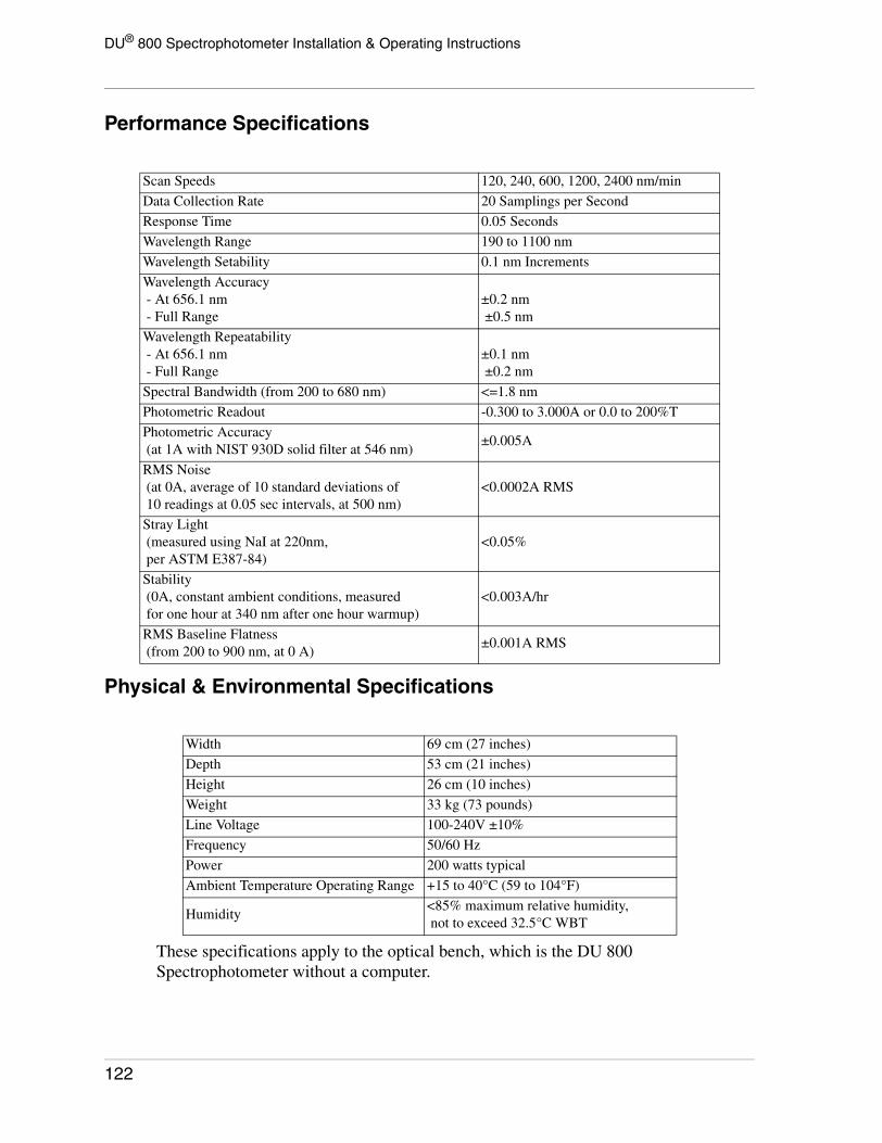
DU® 800 Spectrophotometer Installation & Operating Instructions
Performance Specifications
Physical & Environmental Specifications
These specifications apply to the optical bench, which is the DU 800 Spectrophotometer without a computer.
Scan Speeds 120, 240, 600, 1200, 2400 nm/min
Data Collection Rate 20 Samplings per Second
Response Time 0.05 Seconds
Wavelength Range 190 to 1100 nm
Wavelength Setability 0.1 nm Increments
Wavelength Accuracy - At 656.1 nm - Full Range
±0.2 nm ±0.5 nm
Wavelength Repeatability - At 656.1 nm - Full Range
±0.1 nm ±0.2 nm
Spectral Bandwidth (from 200 to 680 nm) <=1.8 nm
Photometric Readout -0.300 to 3.000A or 0.0 to 200%T
Photometric Accuracy (at 1A with NIST 930D solid filter at 546 nm)
±0.005A
RMS Noise (at 0A, average of 10 standard deviations of 10 readings at 0.05 sec intervals, at 500 nm)
<0.0002A RMS
Stray Light (measured using NaI at 220nm, per ASTM E387-84)
<0.05%
Stability (0A, constant ambient conditions, measured for one hour at 340 nm after one hour warmup)
<0.003A/hr
RMS Baseline Flatness (from 200 to 900 nm, at 0 A)
±0.001A RMS
Width 69 cm (27 inches)
Depth 53 cm (21 inches)
Height 26 cm (10 inches)
Weight 33 kg (73 pounds)
Line Voltage 100-240V ±10%
Frequency 50/60 Hz
Power 200 watts typical
Ambient Temperature Operating Range +15 to 40°C (59 to 104°F)
Humidity<85% maximum relative humidity, not to exceed 32.5°C WBT
122

DU® 800 Spectrophotometer Installation & Operating Instructions
Maintenance
NOTICE
Refer to the SAFETY NOTICE beforefollowing replacing any items. Refer allservicing for procedures not contained inthis section to qualified service personnel.
General InformationThe DU 800 UV/Visible Spectrophotometer is a PC controlled, optical instrument. For the system to operate properly, it is necessary to have adequate ventilation, as described in Installation. It is necessary to operate the instrument below the specified maximum temperature of 40°C (104°F) for adequate cooling.
For the optical components to maintain their quality, it is necessary to operate the instrument in a dust-free, non-corrosive environment. If it is required that the instrument be used in a dusty or corrosive environment, the optical surfaces must be cleaned or replaced periodically. Contact Beckman Coulter Service for more information.
One component of the instrument that can be user-serviced to prevent an interruption in operation is the UV source lamp. With time, its output gradually decreases, close to one- half of the original value, in approximately 1000 hours. At this point in time, it is appropriate to replace the UV source, even though it is not burned out. The length of time that the UV source has been illuminated is shown in the System Status window, accessible in the Diagnostics menu.
A burned out UV source is indicated by the message: "UV LAMP Failure". Instructions for replacing the UV source can be found in UV Source Replacement.
If decreased sensitivity is seen in the visible range, the visible source should be examined to see if a coating has built up on the inside of the glass envelope. If so, the lamp should be replaced. Instructions for replacing the visible source can be found in Visible Source Replacement.
123

DU® 800 Spectrophotometer Installation & Operating Instructions
System StatusThe System Status window, accessible in the Diagnostic Menu, should be examined as part of the Preventive Maintenance program.
Figure 89 System Status Window Screen
The window shows, among other things, the amount of time that both source lamps have been in use. The UV source should be changed at 1000 hours. The visible source should be changed at 2000 hours.
Fuse ReplacementThe only user accessible fuse is the power fuse, located above the receptacle where the power cord is plugged into the instrument. The instrument is shipped with the fuse installed.
1. Turn the instrument OFF.
2. Turn the instrument around so that the back can be accessed.
3. Unplug the power cord from the instrument.
4. The power line module contains a power on/off switch, a power cable receptacle, and a fuse compartment with one fuse installed. To access the fuse, pull and lower the fuse compartment as shown below. The fuse is specified for 100 to 240 VAC (T3A 250V), P/N 890895.
124

DU® 800 Spectrophotometer Installation & Operating Instructions
Figure 90 Fuse Compartment
W A R N I N G
For continued protection against risk of fire,replace the fuses only with the type andcurrent rating specified above.
A T T E N T I O N
Afin d'assurer unne protection permanentecontre les risques d'incendie, remplaceruniquepment par un fusible de meme typeet valeur.
5. Insert the fuse compartment and press to secure.
6. Plug the power cord back into the instrument.
7. Turn the instrument around so that it is facing forward.
8. Turn the instrument ON.
901281L.AI
901289L.AI
125
DU® 800 Spectrophotometer Installation & Operating Instructions
UV Source ReplacementParts Required: UV Source, P/N 514366
1. Turn the instrument off, unplug the power cord and allow the instrument to cool down for 15 minutes.
C A U T I O N
To avoid risk of electrical shock, disconnectpower cord to instrument before changingeither source.
Attention
Risque de choc electrique. Debrancherl'appareil avant de changer de source.
The UV lamp operates at a high temperature. To prevent burns, allow at least 15 minutes for the instrument and sources to cool before handling internal components.
The UV lamp generates UV light. Do not look directly at an operating lamp without wearing proper UV protective eye glasses.
2. Locate the source access door on the top left-hand of the instrument cover, then loosen the thumb screw and open it.
126

DU® 800 Spectrophotometer Installation & Operating Instructions
Figure 91 Location of Source Access Door on DU 800
3. To unplug the connector for the UV source squeeze on the tabs on the sides of the connector, then pull up to release.
Figure 92 Unplugging UV Source Connector
127
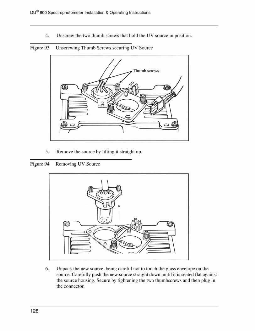
DU® 800 Spectrophotometer Installation & Operating Instructions
4. Unscrew the two thumb screws that hold the UV source in position.
Figure 93 Unscrewing Thumb Screws securing UV Source
5. Remove the source by lifting it straight up.
Figure 94 Removing UV Source
6. Unpack the new source, being careful not to touch the glass envelope on the source. Carefully push the new source straight down, until it is seated flat against the source housing. Secure by tightening the two thumbscrews and then plug in the connector.
128

DU® 800 Spectrophotometer Installation & Operating Instructions
NOTICE
Do not touch the glass envelope on the newsource. If it is touched, clean with alcoholand a soft cloth.
7. Close the source access door and tighten the thumbscrew.
8. Plug in the instrument power cord and turn the spectrophotometer on. Then start the DU 800 System and Applications Software, wait until the system has re-initialized, and press the Continue button to enter the software.
9. Click on Reset Source Hours in the Diagnostic menu under User Diagnostics and reset the hours for the UV source.
Figure 95 Reset Source Hours Screen
Visible Source Replacement
Part I. Replacing the Source
Parts required: Visible Source, P/N514259
1. Unplug the instrument power cord. Allow the instrument to cool for 15 minutes.
C A U T I O N
To avoid risk of electrical shock, disconnectpower cord to instrument before changingeither source.
129

DU® 800 Spectrophotometer Installation & Operating Instructions
Attention
Resque de choc electrique. Debrancherl'appareil avant de changer de source.
The visible lamp operates at a high temperature. To prevent burns, allow at least 15 minutes for the instrument and sources to cool before handling internal components.
2. Locate the source access door on the top left-hand of the instrument cover, then loosen the thumb screw and open it.
Figure 96 Location of Source Access Door on DU 800
130
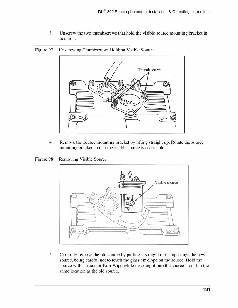
DU® 800 Spectrophotometer Installation & Operating Instructions
3. Unscrew the two thumbscrews that hold the visible source mounting bracket in position.
Figure 97 Unscrewing Thumbscrews Holding Visible Source
4. Remove the source mounting bracket by lifting straight up. Rotate the source mounting bracket so that the visible source is accessible.
Figure 98 Removing Visible Source
5. Carefully remove the old source by pulling it straight out. Unpackage the new source, being careful not to touch the glass envelope on the source. Hold the source with a tissue or Kim-Wipe while inserting it into the source mount in the same location as the old source.
131

DU® 800 Spectrophotometer Installation & Operating Instructions
NOTICE
Do not touch the glass envelope on the newsource. If it is touched, clean with alcoholand a soft cloth.
Figure 99 Installing New Visible Source
6. Replace the source mounting bracket and tighten the two thumbscrews.
Part II. Peaking the Source
Tool required: Peaking tool (provided in the shipping kit)
1. Make sure the instrument is turned on and has been initialized by the DU 800 System and Applications Software.
2. Turn the Visible Source ON.
3. Select the Kinetics/Time applikcation and choose the <Default Method>.
4. Click the Edit Method button and change the Interval time to 1.5 seconds, then click OK.
5. Click on the Blank icon button to blank the instrument on air and the click on the Read button. A reading of approximately 0 Abs. is displayed as data is collected.
6. To peak the source, slightly loosen the two thumbscrews that secure the visible source mounting bracket.
132
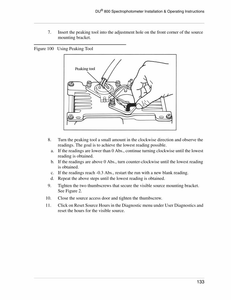
DU® 800 Spectrophotometer Installation & Operating Instructions
7. Insert the peaking tool into the adjustment hole on the front corner of the source mounting bracket.
Figure 100 Using Peaking Tool
8. Turn the peaking tool a small amount in the clockwise direction and observe the readings. The goal is to achieve the lowest reading possible.
a. If the readings are lower than 0 Abs., continue turning clockwise until the lowest reading is obtained.
b. If the readings are above 0 Abs., turn counter-clockwise until the lowest reading is obtained.
c. If the readings reach -0.3 Abs., restart the run with a new blank reading.d. Repeat the above steps until the lowest reading is obtained.
9. Tighten the two thumbscrews that secure the visible source mounting bracket. See Figure 2.
10. Close the source access door and tighten the thumbscrew.
11. Click on Reset Source Hours in the Diagnostic menu under User Diagnostics and reset the hours for the visible source.
133

DU® 800 Spectrophotometer Installation & Operating Instructions
Figure 101 Reset Source Hours Screen
134

DU® 800 Spectrophotometer Installation & Operating Instructions
Troubleshooting
Startup Diagnostic TestsWhen the DU 800 System and Applications Software is launched and an instrument is detected on the USB port, the software downloads the firmware to the DU 800, builds the wavelength calibration table, and then executes a series of diagnostic tests to ensure proper operation of major system components. As the tests are performed, the entire progress and the individual results are displayed. When the tests are complete, the software may be used.
Figure 102 DU 800 System Initialization Screen
Following the test name is Passed or >>> FAILED <<<. If any of the tests fail, click on the Cancel button and then power down the instrument. Wait a few seconds and then power it up again. If the failure persists, the instrument may be partially operational as described in the following table.
The Visible Lamp and Light Path failures can be corrected by the user. If the problem persists, contact the local Beckman Coulter service office. If any other test fails, contact the local Beckman Coulter office.
135

DU® 800 Spectrophotometer Installation & Operating Instructions
Operational FailuresThere are three failures that can occur during instrument operation. These are displayed in the Permanent Menu Bar on the left-hand side. The failure is displayed until the condition is corrected.
Failed Test ExplanationDetector Readings cannot be takern.The instrument can be used for other functions.
Gain Readings cannot be taken. The instrument can be used for other functions.
Visible LampReplace the visible source. Directions are provided in Visible Source Replacement.
Light PathSomething is blocking the light path through the sample compartment. Remove the sampling accessory and re-initialize the system.
Shutter Readings cannot be taken. The instrument can be used for other functions.
Filter Readings cannot be taken. The instrument can be used for other functions.
EEPROM Readings cannot be taken. The instrument can be used for other functions.
Wavelength DriveThe wavelength may not be accurate. Use the instrument only if the accuracy of the readings can be verified. Contact the Beckman Coulter service.
Message Recommended Action
VISIBLE LAMP FailureReplace the visible source. Directions are given in Visible Source Replacement.
UV LAMP FailureReplace the UV source. Directions are given in UV Source Replacement.
Visible LampReplace the visible source. Directions are provided in Visible Source Replacement.
Light PathSomething is blocking the light path through the sample compartment. Remove the sampling accessory and re-initialize the system.
Filter Readings cannot be taken The instrument can be used for other functions.
Lamp SelectorReadings cannot be taken. The instrument can be used for other functions.
Wavelength DriveThe wavelength may not be accurate. Use the instrument only if the accuracy of the readings can be verified. Contact the Beckman Coulter service.
136

DU® 800 Spectrophotometer Installation & Operating Instructions
Operational MessagesThe following messages can occur while operating the instrument and are displayed in an error window. In most cases, these errors do not indicate an instrument malfunction but a situation where an action was initiated that the instrument cannot perform.
If the instrument requires operator action to continue, the message is given in the form of a message window and the user must click on OK to remove the window.
Message Explanation and Recommended Action
Blank RequiredPlace a cuvette with solvent in the cell holder and click the BLANK icon button. Any reading taken without a blank is invalid.
UV Lamp RequiredTurn on the UV source. Wait for the UV source to warm up and blank the instrument. Any reading taken without the proper source on is invalid.
Visible Lamp RequiredTurn on the visible source and blank the instrument. Any reading taken without the proper source on is invalid.
137

DU® 800 Spectrophotometer Installation & Operating Instructions
138

DU® 800 Spectrophotometer Installation & Operating Instructions
Service and Support
Please make sure to complete and return the Warranty Registration after installation.
This will guarantee that your system will be registered and that the one-year warranty is applied properly. It also assures quick and easy access to the Beckman Coulter Product Support team for answers to your questions.
Warranty RegistrationThe Warranty Registration form is included under separate cover. If you have not done so, please complete the form and return to the address indicated.
Customer SupportMarketing Support
(800) 551-1150(800) 742-2345
For North America Only
139

DU® 800 Spectrophotometer Installation & Operating Instructions
Beckman Coulter Offices
North America
United States
Beckman Coulter, Inc. (Headquarter)4300 N. Harbor BoulevardP. O. Box 3100Fullerton, California 92834-3100USA
Phone: General (714) 871-4848Phone: Sales (800) 742-2345Phone: Service (800) 551-1150FAX: (800) 643-4366FAX: (714) 773-8283
Canada
Beckman Coulter Canada Inc.6755 Mississauga Road, Suite 600Mississauga, Ontario, Canada L5N 7Y2
Phone: (800) 387-6799 BCOFAX: (905) 819-1485
Latin America
Mexico
Beckman Coulter de MexicoAdolfo Prieto 1213Colonia del Valle A.P. 44-100 Mexico D.F. 03100
Phone: (52-5) 559-1635FAX: (52-5) 559-3941E-Mail: [email protected]
140
DU® 800 Spectrophotometer Installation & Operating Instructions
Europe
France
Beckman Coulter France S.A.Paris Nord II33 rue des VanessesBP 50359 VILLEPINTE95942 ROISSY CDG Cedex
Phone: 33 (0)1 49 90 90 00FAX: 33 (0)1 49 90 90 10E-Mail: [email protected]
Germany
Beckman Coulter GmbH Siemensstrasse 1D-85716 Unterschleissheim-Lohhof
Phone: 49-89-35-870-0 (Switchboard)FAX: 49-89-35-870-490 (Gen’l Fax)
Italy
Beckman Coulter S.p.A.Centro Direzionale LombardoPalazzo F/1, Via Roma 10820060 Cassina De'PecchiMilano
Phone: (34) 02 953921FAX: (34) 02 95392264E-Mail: [email protected]
Netherlands
Beckman Coulter ( Nederland ) B.V.Nijverheidsweg 213641 RP MijdrechtP.O. Box 473640 AA Mijdrecht,
Phone: 31-(0)297-230630FAX: 31-(0)297-288082
141
DU® 800 Spectrophotometer Installation & Operating Instructions
Spain
Beckman Coulter España S.A.Avda. del Llano Castellano 1528034 Madrid
Phone: (34) 91 383 6080FAX: (34) 91 383 6096E-Mail: [email protected]
Sweden
Beckman Coulter ABArchimedesvagen 7Box 11156S-16811 Bromma
Phone: 46 8 564 859 00FAX: 46 8 564 859 01E-Mail: [email protected]
Switzerland
Beckman Coulter Intl SA (Swiss Domestic Operation)22, Rue Juste-OlivierCase Postale 301-303CH-1260 Nyon , Switzerland
Phone: (41) 22 994 0707FAX: (41) 22 994 0700
Turkey
Beckman Coulter Ltd/TurkeyE-5 Yanyol Fatih Cad.81410 Soganlik KartalIstanbul
Phone: + 90 216 309 1900FAX: + 90 216 309 0090
United Kingdom
Beckman Coulter (U.K.) LimitedOakley CourtKingsmead Business ParkLondon RoadHigh WycombeBuckinghamshire HP11 1JU, England
Phone: (44) 1494-441181FAX: (44) 1494-447558E-Mail: [email protected]
142

DU® 800 Spectrophotometer Installation & Operating Instructions
Asia/Pacific
Australia
Beckman Coulter Australia Pty. Ltd.24 College StreetGladesville, NSW, 2111
Phone: (61) 2-9844-6000Phone: 1 800 060 880FAX: (61) 2-9844-6096 Sales & MarketingFAX: (61) 2-9844-6098 Service
China
Beckman Coulter Inc. Beijing Representative OfficeUnit 2005A, 2006-2009, East Ocean Center24 Jian Guo Men Wai AvenueBeijing 100004
Phone: 86-10-6515-6028FAX: 86-10-6515-6025
Hong Kong
Beckman Coulter Hong Kong Ltd.12th Floor, Oxford House979 King's RoadTaiKoo Place
Phone: 852-2814-7431Phone: 852-2814-0481FAX: 852-2814-1599FAX: 852-2873-4511E-Mail: [email protected]
Japan
Beckman Coulter K.K.Toranomon 37 Mori Building3-5-1 Toranomon, Minato-kuTokyo 105-0001
Phone: +81 (3) 5404-8359FAX: +81 (3) 5404-8436
143

DU® 800 Spectrophotometer Installation & Operating Instructions
Singapore
Beckman Coulter Singapore Pte Ltd.116 Changi RoadUnit 03-01/02Singapore 419718
Phone: (65) 339 3633FAX: (65) 336 6303
Taiwan
Beckman Coulter Taiwan Inc., Taiwan Branch8th Floor216 Tun Hwa South Road, Section 2Taipei 106Taiwan
Phone: 886-2-2378-3456Phone: 886-2-2378-8000FAX: 886-2-2377-0408
Eastern Europe, Middle East, Africa
Beckman Coulter Intl SA22, rue Juste-OliverP.O. Box 3031260 Nyon, Switzerland
Phone: (41) 22 994 0707FAX: (41) 22 994 0700
South Africa
Beckman Instruments Pty. Ltd.(Johannesburg)(Postal) P.O. Box 1949Halway House 1949(Physical) Stand 1A Fedsure ParkTonetti Street, 1685 Halway HouseJohannesburg
Phone: (27) 11 805-2014 or (27) 11 805-1015FAX: (27) 11 805-4120
144