beatrice offshore wind farm consent planmarine.gov.scot/sites/default/files/00510248.pdf · wind...
TRANSCRIPT
Beatrice Offshore
Wind Farm
Consent Plan
Development Specification and Layout Plan
November 2016

BOWL Development Specification and Layout Plan
Page 2 of 49
Document Reference
LF000005- PLN-152
Rev 3.0
[Page intentionally left blank]
Rev Prepared By Sign Off Checked By Sign Off Approved By Sign Off Date of Issue
3.0
Steve Bellew
GoBe Consultants
Jonathan Wilson, Consenting and
Stakeholder Manager, BOWL
Steven Wilson,
Senior PM, BOWL
04/11/2016
BOWL Development Specification and Layout Plan
Page 3 of 49
Document Reference
LF000005- PLN-152
Rev 3.0
Beatrice Offshore Wind Farm
Development Specification and Layout
Plan
Pursuant to Section 36 Consent Condition 13 and the Marine Licence
(Offshore Transmission Works) Condition 3.2.2.6 (Partial)
For the approval of the Scottish Ministers
This document contains proprietary information belonging to Beatrice Offshore Windfarm Ltd
and/or affiliated companies and shall be used only for the purpose for which it was supplied.
It shall not be copied, reproduced, disclosed or otherwise used, nor shall such information be
furnished in whole or in part to third parties, except in accordance with the terms of any
agreement under which it was supplied or with the prior consent of Beatrice Offshore Windfarm
Ltd and shall be returned upon request.
© Copyright of Beatrice Offshore Windfarm Ltd 2016.
Project Title/ Location Beatrice Offshore Wind Farm
Project Reference Number LF0000005
Date: November 2016
LF000005-PLN-152
BOWL Development Specification and Layout Plan
Document Reference
LF000005-PLN-152
Rev 3.0
Page 4 of 49
Table of Contents
1 Introduction .................................................................................................................. 8
1.1 Background ......................................................................................................................... 8
1.2 Objectives of this Document ............................................................................................... 8
1.3 DSLP Document Structure ................................................................................................ 11
1.4 Linkages with other Consent Plans ................................................................................... 11
2 BOWL Statements of Compliance ............................................................................. 13
2.1 Introduction ........................................................................................................................ 13
2.2 Statements of Compliance ................................................................................................ 13
3 Updates and Amendments to this DSLP .................................................................. 14
4 Design, Specification and Layout – Wind Farm ....................................................... 16
4.1 Introduction ........................................................................................................................ 16
4.2 Wind Farm Layout and Specification ................................................................................ 16
4.3 Co-ordinates for Wind Turbine Locations ......................................................................... 25
4.4 Wind Turbine Dimensions ................................................................................................. 27
4.5 Generating Capacity ......................................................................................................... 29
4.6 Wind Turbine Finishes ...................................................................................................... 29
4.7 Inter-Array Cable Arrangement and Lengths .................................................................... 29
5 Design, Specification and Layout – Offshore Transformer Modules...................... 38
5.1 Introduction ........................................................................................................................ 38
5.2 Offshore Transformer Modules Layout and Specification ................................................. 38
5.3 Co-ordinates for Offshore Transformer Module Locations................................................ 38
5.4 Offshore Transformer Module Dimensions ....................................................................... 39
5.5 Offshore Transformer Module Finishes ............................................................................ 43
5.6 Length and Proposed Arrangements of Cables ................................................................ 43
6 Compliance with the Application .............................................................................. 44
6.1 Introduction ........................................................................................................................ 44
6.2 Compliance with the Specification and Layout Assessed in the ES/SEIS ........................ 44
6.3 Delivery of Design-related Mitigation Proposed in the ES/SEIS ....................................... 44
Appendix A – Comparison of ES/SEIS Rochdale Envelope and DSLP design
parameters ........................................................................................................................ 46
Appendix B - ES and SEIS Mitigation Commitments ...................................................... 48
Appendix C – GIS information to Support the DSLP ...................................................... 49
LF000005-PLN-152
BOWL Development Specification and Layout Plan
Document Reference
LF000005-PLN-152
Rev 3.0
Page 5 of 49
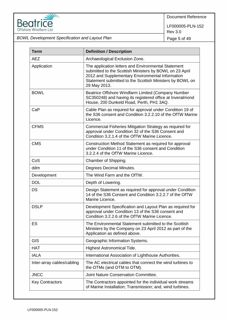
Term Definition / Description
AEZ Archaeological Exclusion Zone.
Application The application letters and Environmental Statement submitted to the Scottish Ministers by BOWL on 23 April 2012 and Supplementary Environmental Information Statement submitted to the Scottish Ministers by BOWL on 29 May 2013.
BOWL Beatrice Offshore Windfarm Limited (Company Number SC350248) and having its registered office at Inveralmond House, 200 Dunkeld Road, Perth, PH1 3AQ.
CaP Cable Plan as required for approval under Condition 19 of the S36 consent and Condition 3.2.2.10 of the OfTW Marine Licence.
CFMS Commercial Fisheries Mitigation Strategy as required for approval under Condition 32 of the S36 Consent and Condition 3.2.1.4 of the OfTW Marine Licence.
CMS Construction Method Statement as required for approval under Condition 11 of the S36 consent and Condition 3.2.2.4 of the OfTW Marine Licence.
CoS Chamber of Shipping.
ddm Degrees Decimal Minutes.
Development The Wind Farm and the OfTW.
DOL Depth of Lowering.
DS Design Statement as required for approval under Condition 14 of the S36 Consent and Condition 3.2.2.7 of the OfTW Marine Licence.
DSLP Development Specification and Layout Plan as required for approval under Condition 13 of the S36 consent and Condition 3.2.2.6 of the OfTW Marine Licence.
ES The Environmental Statement submitted to the Scottish Ministers by the Company on 23 April 2012 as part of the Application as defined above.
GIS Geographic Information Systems.
HAT Highest Astronomical Tide.
IALA International Association of Lighthouse Authorities.
Inter-array cables/cabling The AC electrical cables that connect the wind turbines to the OTMs (and OTM to OTM).
JNCC Joint Nature Conservation Committee.
Key Contractors The Contractors appointed for the individual work streams of Marine Installation; Transmission; and, wind turbines.
LF000005-PLN-152
BOWL Development Specification and Layout Plan
Document Reference
LF000005-PLN-152
Rev 3.0
Page 6 of 49
Term Definition / Description
LAT Lowest Astronomical Tide.
Licensing Authority The Scottish Ministers.
LMP Lighting and Marking Plan as required for approval under Condition 20 of the S36 consent and Condition 3.2.2.14 of the OfTW Marine Licence.
Marine Licences The written consents granted by the Scottish Ministers under Section 20(1) of the Marine (Scotland) Act 2010, which are dated 2 September 2014.
MCA Maritime and Coastguard Agency.
MS - LOT Marine Scotland Licensing Operations Team.
MW Megawatts.
NLB Northern Lighthouse Board.
OfTW The Offshore Transmission Works. The OfTW includes the transmission cable required to connect the Wind Farm to the OnTW. This covers the OTMs and the cable route from the OTMs to the Mean High Water Springs (MHWS) at the landfall west of Portgordon on the Moray coast.
OfTW Marine Licence The written consent for the OfTW granted by the Scottish Ministers under Section 20(1) of the Marine (Scotland) Act 2010 and Section 65 of the Marine and Coastal Access Act 2009, issued on 2 September 2014, as revised by the issue of licence 04461/16/0 on 27 April 2016.
OfTW CMS The Construction Method Statement in respect of the export cable installation and OTM commissioning to be submitted for approval under Condition 3.2.2.4 of the OfTW Marine Licence.
OfTW DSLP The Development Site Layout Plan in respect of the export cable installation to be submitted for approval under Condition 3.2.2.6 of the OfTW Marine Licence.
OSP Offshore Substation Platform.
OTM Offshore Transformer Module means an alternating current (AC) OSP which is a standalone modular unit that utilises the same substructure and foundation design as a wind turbine generator.
PS Piling Strategy as required for approval under Condition 12 of the S36 Consent and Condition 3.2.2.5 of the OfTW Marine Licence.
RAL System for defining standard colours for paint and coatings.
rpm Revolutions Per Minute.
RYA Royal Yachting Association.
LF000005-PLN-152
BOWL Development Specification and Layout Plan
Document Reference
LF000005-PLN-152
Rev 3.0
Page 7 of 49
Term Definition / Description
S36 Consent Consent granted by the Scottish Ministers under Section 36 of The Electricity Act 1989 to construct and operate the Beatrice Offshore Wind farm electricity generating station, dated 19th March 2014.
SAR Search and Rescue.
SEIS The Supplementary Environmental Information Statement submitted to the Scottish Ministers by the Company on 29 May 2013 as part of the Application as defined above.
SFF Scottish Fishermen’s Federation.
Site The area outlined in red in Figure 1 attached to the (S36) Consent Annex 1 and the area outlined in red and the area outlined in black in the figure contained in Part 4 of the (OfTW) Marine Licence.
SNH Scottish Natural Heritage.
Subcontractors Subcontractors to Key Contractors as defined above.
SWT Siemens Wind Turbine.
WGS84 World Geodetic System 1984; the reference coordinate system used by the Global Positioning System.
Wind Farm The offshore array development as assessed in the ES including wind turbines, their foundations, inter-array cabling and meteorological masts.
Wind Farm Marine Licence
The written consent for the Wind Farm granted by the Scottish Ministers under Section 20(1) of the Marine (Scotland) Act 2010, issued on 2 September 2014, as revised by the issue of licence 04462/16/0 on 27 April 2016.
WTG Wind Turbine Generator.
LF000005-PLN-152
BOWL Development Specification and Layout Plan
Document Reference
LF000005-PLN-152
Rev 3.0
Page 8 of 49
1 Introduction
1.1 Background
1.1.1 The Beatrice Offshore Wind Farm received consent under Section 36 of the Electricity
Act 1989 from the Scottish Ministers on 19 March 2014 (the S36 Consent) and was
granted two Marine Licences from the Scottish Ministers, for the Wind Farm and
associated Offshore Transmission Works (OfTW), on 2nd September 2014 (the Marine
Licences) and revised by the issue of licences on 27 April 2016 (Reference: 04461/16/0
and 04462/16/0 respectively.
1.2 Objectives of this Document
1.2.1 The S36 Consent and Marine Licences contain a variety of conditions that must be
discharged through approval by the Scottish Ministers prior to the commencement of
offshore construction. One such requirement is the approval of the proposed layout
and specification of the Wind Farm and OfTW design through the preparation and
approval of a Design Specification and Layout Plan (DSLP).
1.2.2 The relevant conditions setting out the requirement for a DSLP for approval are set out
in full in Table 1.1.
1.2.3 This document is intended to satisfy the requirements of the S36 and the OfTW Marine
Licence conditions by providing details of the proposed design and layout specification.
1.2.4 It should be noted that this DSLP is intended to provide full details to allow the complete
discharge of the relevant S36 Consent condition and the partial discharge of the OfTW
Marine Licence condition in so far as it relates to the offshore substation platforms
(OSPs), referred to as offshore transformer modules (OTMs).
1.2.5 A separate OfTW DSLP (LF000005-PLN-181) has been prepared for the remainder of
the OfTW (i.e. the export cables).
Table 1.1 - Consent conditions to be discharged by this Wind Farm DSLP
Consent Document
Condition Reference
Condition Text Reference to relevant Section of this DSLP
Section 36 13 The Company must, no later than 6 months prior to the Commencement of the Development, submit a DSLP in writing, to the Scottish Ministers for their written approval.
This document sets out the DSLP for approval by the Scottish Ministers
Such approval may only be granted following consultation by the Scottish Ministers with the Maritime and Coastguard Agency (MCA), Northern Lighthouse Board (NLB), Chamber of Shipping (CoS), the Joint Nature Conservation Committee (JNCC), Scottish Natural Heritage (SNH), Scottish
Consultation to be undertaken by the Scottish Ministers
LF000005-PLN-152
BOWL Development Specification and Layout Plan
Document Reference
LF000005-PLN-152
Rev 3.0
Page 9 of 49
Consent Document
Condition Reference
Condition Text Reference to relevant Section of this DSLP
Fishermen’s Federation (SFF) and any such other advisors or organisations as may be required at the discretion of the Scottish Ministers.
The Development must, at all times, be constructed in accordance with the approved DSLP (as updated and amended from time to time by the Company).
Section 2.0
Any updates or amendments made to the DSLP by the Company must be submitted, in writing, by the Company to the Scottish Ministers for their written approval.
Section 3.0
The DSLP must include, but not be limited to the following:
a) A plan showing the proposed location of each individual Wind Turbine Generator (WTG) (subject to any required micro-siting), including information on WTG spacing, WTG identification / numbering, location of the substation platforms, seabed conditions, bathymetry, confirmed foundation type for each WTG and any key constraints recorded on the Site;
Section 4.2
b) A list of latitude and longitude co-ordinates accurate to three decimal places of minutes for each WTG, this should also be provided as a Geographic Information System (GIS) shape file using WGS84 format;
Section 4.3 and GIS data in Appendix C
c) A table or diagram of each WTG dimensions including - height to blade tip (measured above Highest Astronomical Tide (HAT)), height to hub (measured above HAT to the centreline of the generator shaft), rotor diameter and rotation speed;
Section 4.4
d) The generating capacity of each WTG used on the Site and a confirmed generating capacity for the Site overall;
Section 4.5
e) The finishes for each WTG (see condition 20 on WTG lighting and marking); and
Section 4.6
f) The length and proposed arrangements on the seabed of all inter-array cables.
Section 4.7
OFTW Marine Licence
3.2.2.6 The Licensee must, no later than 6 months prior to the Commencement of the Works, submit a DSLP, in writing, to the Licensing Authority for their written approval.
This document sets out the DSLP in so far as it relates to the offshore substation platforms (OSPs),
LF000005-PLN-152
BOWL Development Specification and Layout Plan
Document Reference
LF000005-PLN-152
Rev 3.0
Page 10 of 49
Consent Document
Condition Reference
Condition Text Reference to relevant Section of this DSLP
referred to as offshore transformer modules (OTMs) for approval by the Scottish Ministers
Such approval may only be granted following consultation by the Licensing Authority with the MCA, NLB, CoS, JNCC, SNH, SFF and any such other advisors or organisations as may be required at the discretion of the Licensing Authority.
Consultation to be undertaken by the Scottish Ministers
The DSLP must include, but not be limited to the following:
a) A plan showing the proposed location of each individual OSP, seabed conditions, bathymetry, confirmed foundation type for each OSP and any key constraints recorded on the Site;
Section 5.2
b) A list of latitude and longitude co-ordinates accurate to three decimal places of minutes for each OSP, this should also be provided as a GIS shape file using WGS84 format;
Section 5.3 and GIS data in Appendix C
c) A table or diagram of each OSP; Section 5.4
d) The finishes for each OSP; and Section 5.5
e) The length and proposed arrangements on the seabed of all cables.
Captured within a separate OfTW DSLP
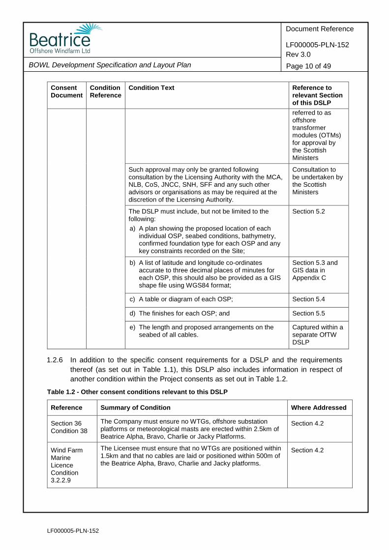
1.2.6 In addition to the specific consent requirements for a DSLP and the requirements
thereof (as set out in Table 1.1), this DSLP also includes information in respect of
another condition within the Project consents as set out in Table 1.2.
Table 1.2 - Other consent conditions relevant to this DSLP
Reference Summary of Condition Where Addressed
Section 36 Condition 38
The Company must ensure no WTGs, offshore substation platforms or meteorological masts are erected within 2.5km of Beatrice Alpha, Bravo, Charlie or Jacky Platforms.
Section 4.2
Wind Farm Marine Licence Condition 3.2.2.9
The Licensee must ensure that no WTGs are positioned within 1.5km and that no cables are laid or positioned within 500m of the Beatrice Alpha, Bravo, Charlie and Jacky platforms.
Section 4.2
LF000005-PLN-152
BOWL Development Specification and Layout Plan
Document Reference
LF000005-PLN-152
Rev 3.0
Page 11 of 49
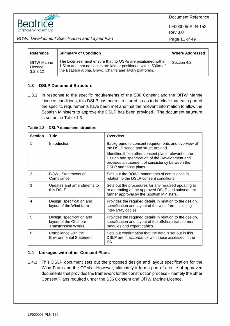
Reference Summary of Condition Where Addressed
OfTW Marine Licence 3.2.3.12
The Licensee must ensure that no OSPs are positioned within 1.5km and that no cables are laid or positioned within 500m of the Beatrice Alpha, Bravo, Charlie and Jacky platforms.
Section 4.2
1.3 DSLP Document Structure
1.3.1 In response to the specific requirements of the S36 Consent and the OfTW Marine
Licence conditions, this DSLP has been structured so as to be clear that each part of
the specific requirements have been met and that the relevant information to allow the
Scottish Ministers to approve the DSLP has been provided. The document structure
is set out in Table 1.3.
Table 1.3 – DSLP document structure
Section Title Overview
1 Introduction Background to consent requirements and overview of the DSLP scope and structure; and
Identifies those other consent plans relevant to the Design and specification of the Development and provides a statement of consistency between the DSLP and those plans.
2 BOWL Statements of Compliance
Sets out the BOWL statements of compliance in relation to the DSLP consent conditions.
3 Updates and amendments to this DSLP
Sets out the procedures for any required updating to or amending of the approved DSLP and subsequent further approval by the Scottish Ministers.
4 Design, specification and layout of the Wind farm
Provides the required details in relation to the design, specification and layout of the wind farm including inter-array cables.
5 Design, specification and layout of the Offshore Transmission Works
Provides the required details in relation to the design, specification and layout of the offshore transformer modules and export cables.
6 Compliance with the Environmental Statement
Sets out confirmation that the details set out in this DSLP are in accordance with those assessed in the ES.
1.4 Linkages with other Consent Plans
1.4.1 This DSLP document sets out the proposed design and layout specification for the
Wind Farm and the OTMs. However, ultimately it forms part of a suite of approved
documents that provides the framework for the construction process – namely the other
Consent Plans required under the S36 Consent and OfTW Marine Licence.
LF000005-PLN-152
BOWL Development Specification and Layout Plan
Document Reference
LF000005-PLN-152
Rev 3.0
Page 12 of 49
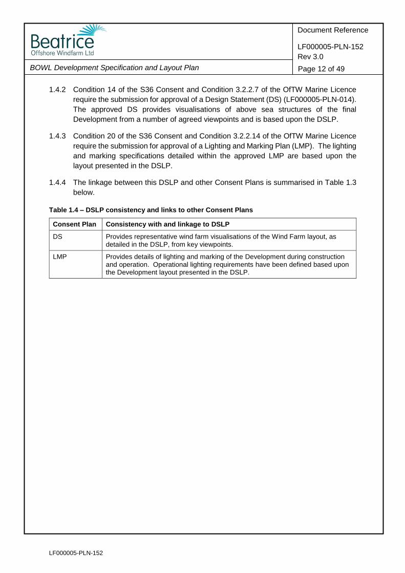
1.4.2 Condition 14 of the S36 Consent and Condition 3.2.2.7 of the OfTW Marine Licence
require the submission for approval of a Design Statement (DS) (LF000005-PLN-014).
The approved DS provides visualisations of above sea structures of the final
Development from a number of agreed viewpoints and is based upon the DSLP.
1.4.3 Condition 20 of the S36 Consent and Condition 3.2.2.14 of the OfTW Marine Licence
require the submission for approval of a Lighting and Marking Plan (LMP). The lighting
and marking specifications detailed within the approved LMP are based upon the
layout presented in the DSLP.
1.4.4 The linkage between this DSLP and other Consent Plans is summarised in Table 1.3
below.
Table 1.4 – DSLP consistency and links to other Consent Plans
Consent Plan Consistency with and linkage to DSLP
DS Provides representative wind farm visualisations of the Wind Farm layout, as detailed in the DSLP, from key viewpoints.
LMP Provides details of lighting and marking of the Development during construction and operation. Operational lighting requirements have been defined based upon the Development layout presented in the DSLP.
LF000005-PLN-152
BOWL Development Specification and Layout Plan
Document Reference
LF000005-PLN-152
Rev 3.0
Page 13 of 49
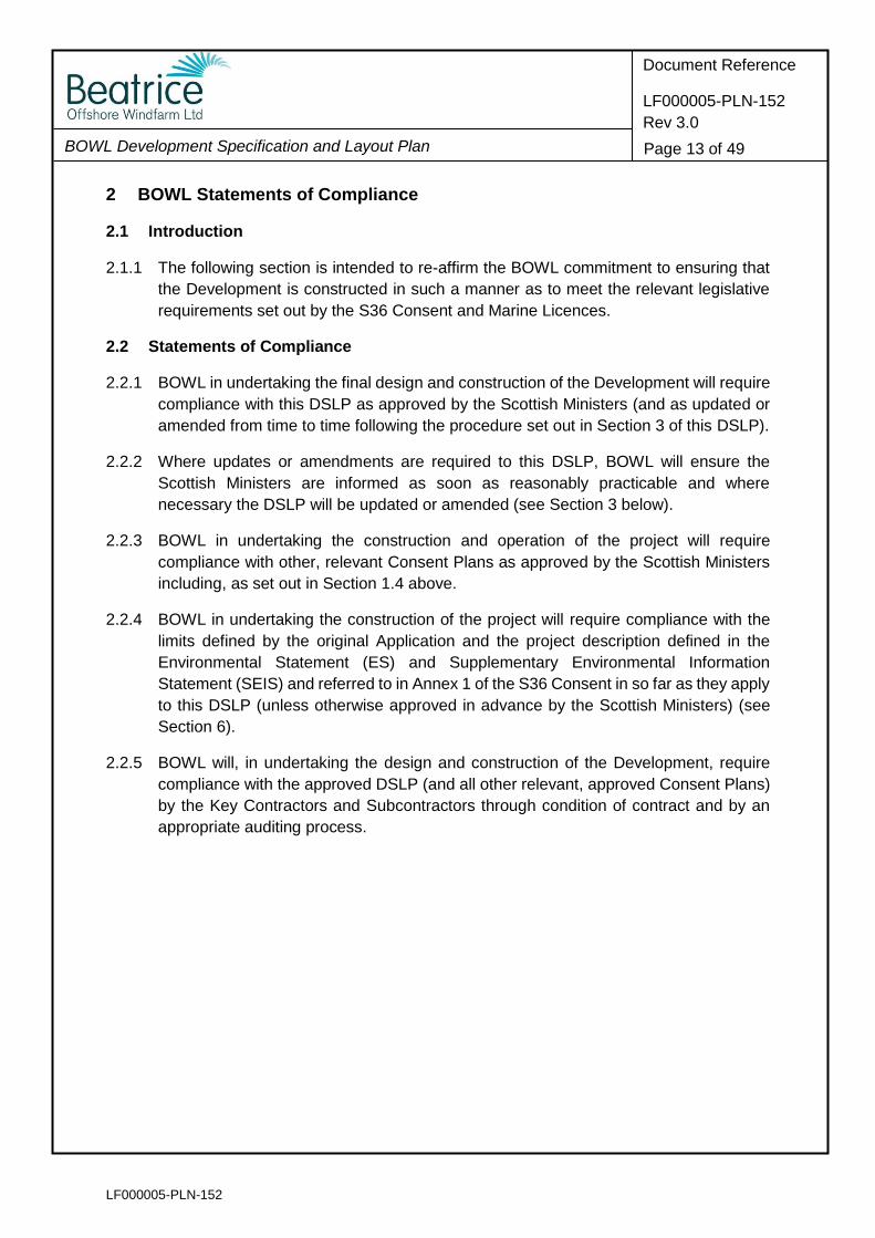
2 BOWL Statements of Compliance
2.1 Introduction
2.1.1 The following section is intended to re-affirm the BOWL commitment to ensuring that
the Development is constructed in such a manner as to meet the relevant legislative
requirements set out by the S36 Consent and Marine Licences.
2.2 Statements of Compliance
2.2.1 BOWL in undertaking the final design and construction of the Development will require
compliance with this DSLP as approved by the Scottish Ministers (and as updated or
amended from time to time following the procedure set out in Section 3 of this DSLP).
2.2.2 Where updates or amendments are required to this DSLP, BOWL will ensure the
Scottish Ministers are informed as soon as reasonably practicable and where
necessary the DSLP will be updated or amended (see Section 3 below).
2.2.3 BOWL in undertaking the construction and operation of the project will require
compliance with other, relevant Consent Plans as approved by the Scottish Ministers
including, as set out in Section 1.4 above.
2.2.4 BOWL in undertaking the construction of the project will require compliance with the
limits defined by the original Application and the project description defined in the
Environmental Statement (ES) and Supplementary Environmental Information
Statement (SEIS) and referred to in Annex 1 of the S36 Consent in so far as they apply
to this DSLP (unless otherwise approved in advance by the Scottish Ministers) (see
Section 6).
2.2.5 BOWL will, in undertaking the design and construction of the Development, require
compliance with the approved DSLP (and all other relevant, approved Consent Plans)
by the Key Contractors and Subcontractors through condition of contract and by an
appropriate auditing process.
LF000005-PLN-152
BOWL Development Specification and Layout Plan
Document Reference
LF000005-PLN-152
Rev 3.0
Page 14 of 49
3 Updates and Amendments to this DSLP
3.1.1 This DSLP sets out the proposed design and layout specification for the Wind Farm
and offshore transmission components of the Wind Farm and OTMs.
3.1.2 The S36 Consent condition recognises that updates or amendments to this DSLP may
be required, stating that:
The Development [Wind Farm] must, at all times, be constructed in accordance with the approved DSLP (as updated and amended from time to time by the Company [BOWL]). Any updates or amendments made to the DSLP by the Company [BOWL] must be submitted, in writing, by the Company [BOWL] to the Scottish Ministers for their written approval.
3.1.3 The main design and layout specifications for both the Wind Farm and OTMs are
described in this DSLP including:
Wind turbine and OTM layout plans;
Wind turbine and OTM location co-ordinates;
Wind turbine and OTM specifications (including wind turbine generating capacity and total Development generating capacity);
Wind turbine and OTM finishes; and
Inter-array lengths and arrangements.
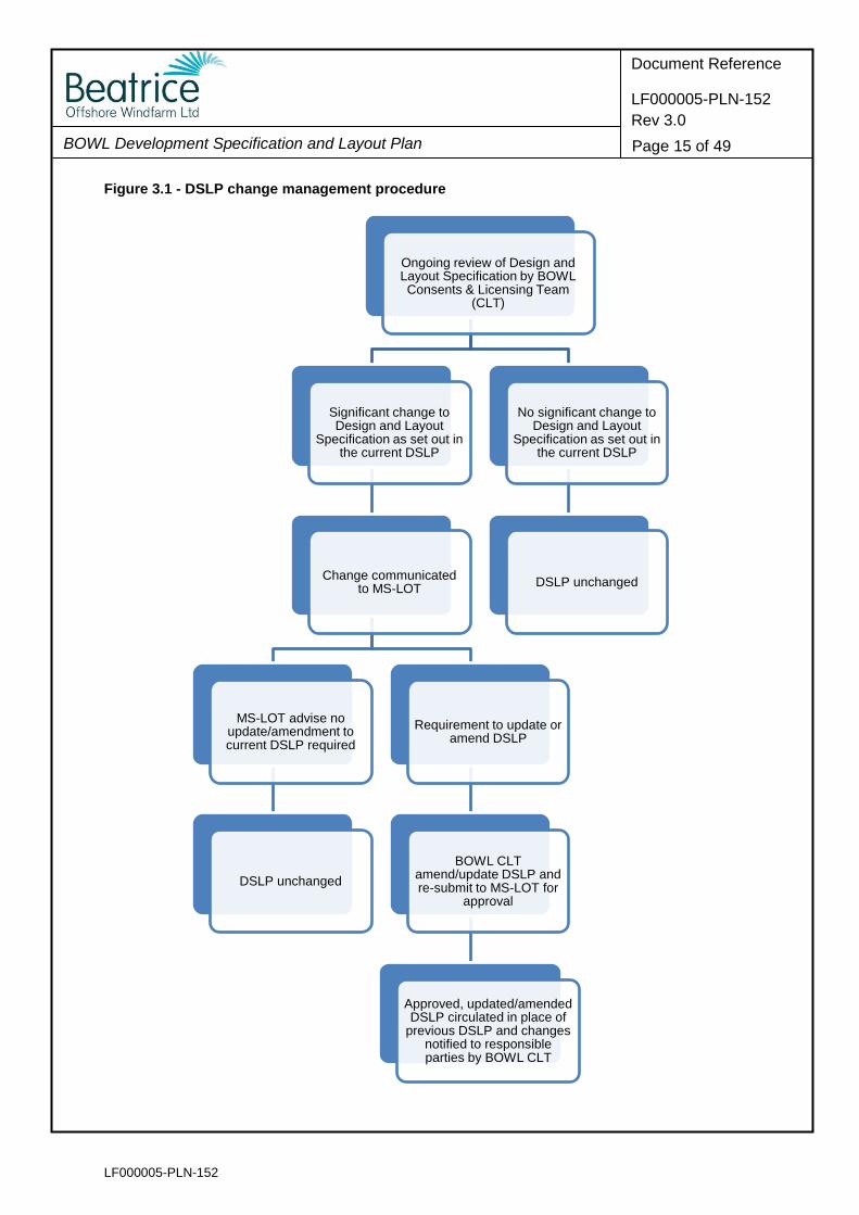
3.1.4 Where it is necessary to update this DSLP in light of any significant new information
related to the design and layout specification, BOWL proposes to use the change
management process set out in Figure 3.1 in identifying such information,
communicating such change to the Scottish Ministers, re-drafting the DSLP, seeking
further approval for the necessary amendments or updates and disseminating the
approved changes/amendments to responsible parties.
LF000005-PLN-152
BOWL Development Specification and Layout Plan
Document Reference
LF000005-PLN-152
Rev 3.0
Page 15 of 49
Figure 3.1 - DSLP change management procedure
Ongoing review of Design and Layout Specification by BOWL Consents & Licensing Team
(CLT)
Significant change to Design and Layout
Specification as set out in the current DSLP
Change communicated to MS-LOT
MS-LOT advise no update/amendment to current DSLP required
DSLP unchanged
Requirement to update or amend DSLP
BOWL CLT amend/update DSLP and re-submit to MS-LOT for
approval
Approved, updated/amended DSLP circulated in place of
previous DSLP and changes notified to responsible parties by BOWL CLT
No significant change to Design and Layout
Specification as set out in the current DSLP
DSLP unchanged
LF000005-PLN-152
BOWL Development Specification and Layout Plan
Document Reference
LF000005-PLN-152
Rev 3.0
Page 16 of 49
4 Design, Specification and Layout – Wind Farm
4.1 Introduction
4.1.1 This section of the DSLP details the wind farm design and layout specification as
required by the S36 Consent condition detailed in Table 1.1. Details related to the
OTMs required by the OfTW Marine Licence condition are provided separately under
Section 5.
4.2 Wind Farm Layout and Specification
4.2.1 S36 Consent Condition 13 requires that this DSLP include the following:
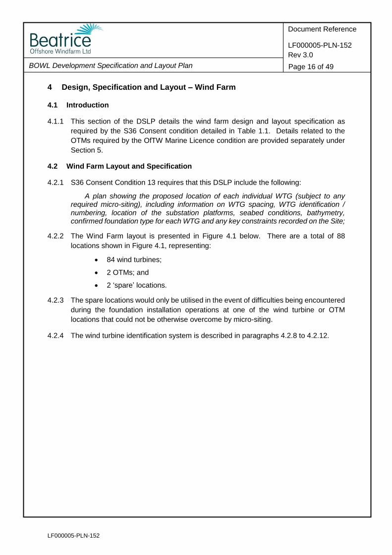
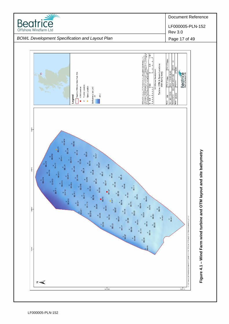
A plan showing the proposed location of each individual WTG (subject to any required micro-siting), including information on WTG spacing, WTG identification / numbering, location of the substation platforms, seabed conditions, bathymetry, confirmed foundation type for each WTG and any key constraints recorded on the Site;
4.2.2 The Wind Farm layout is presented in Figure 4.1 below. There are a total of 88
locations shown in Figure 4.1, representing:
84 wind turbines;
2 OTMs; and
2 ‘spare’ locations.
4.2.3 The spare locations would only be utilised in the event of difficulties being encountered
during the foundation installation operations at one of the wind turbine or OTM
locations that could not be otherwise overcome by micro-siting.
4.2.4 The wind turbine identification system is described in paragraphs 4.2.8 to 4.2.12.
LF000005-PLN-152
BOWL Development Specification and Layout Plan
Document Reference
LF000005-PLN-152
Rev 3.0
Page 17 of 49
Fig
ure
4.1
– W
ind
Fa
rm w
ind
tu
rbin
e a
nd
OT
M layo
ut
an
d s
ite b
ath
ym
etr
y
LF000005-PLN-152
BOWL Development Specification and Layout Plan
Document Reference
LF000005-PLN-152
Rev 3.0
Page 18 of 49
Wind Turbine Spacing
4.2.5 The wind turbines are arranged in a regular geometric pattern that permits navigation
between rows of turbines in any direction. The layout should not preclude commercial
fishing from the wind farm site. A Commercial Fisheries Mitigation Strategy (CFMS)
(LF000005-PLN-130) has been developed in consultation with fishery industry
representatives to ensure co-existence and to explore potential mitigation measures.
4.2.6 The wind turbines are spaced at a distance of approximately 1170 m apart in all
directions, a distance roughly equivalent to 7.6 wind turbine rotor diameters. There are
minor variations in spacing in the layout shown in Figure 4.1. Specifically, the spacing
of 4 turbines differs slightly; this results from turbines which at a spacing of 1170 m lay
marginally outwith the ‘developable area’ (the developable area is shown in Figure 4.4)
being moved to ensure they lie with the developable (red line) boundary. The wind
turbines that are spaced differently are as follows:
BE-C4 (1121.5m to nearest turbine);
BE-D3 (945.5m to nearest turbine);
BE-E1 (1065.5m to nearest turbine); and
BE-G3 (1102m to nearest turbine).
4.2.7 The distances stated are separations pre-micrositing. Micro-siting allows for the
movement of a wind turbine or OTM structure by up to 50m on any axis as measured
from the centrepoint position.
Wind Turbine Identification
4.2.8 Each wind turbine is marked with a unique alpha-numeric identifier, as shown in Figure
4.1. The turbine identification system has been devised in line with the following
principles and/ or requirements:
Each unique turbine or OTM identifier is prefixed with a capital BE for Beatrice;
The unique identifiers consist of a letter and a number;
The use of O and I has been avoided to prevent confusion with numeric characters in line with MCA guidance (MGN 371);
Consideration has been given to ‘SAR lanes’, and facilitating navigation thorough the Wind Farm.
4.2.9 The MCA confirmed that the indicative SAR lanes through the Beatrice Wind Farm
extend in a slight northeast to southwest (and vice versa) direction (letter from the MCA
titled ‘Beatrice Offshore Wind Farm – Search and Rescue and Navigational Safety
Layout Assessment’ dated 21st April 2015). The proposed numbering system has
considered this in that the turbines and OTMs located along these lanes all have the
same letter in their unique identifiers, followed by a descending or ascending number
from the next turbine/ OTM along the lane, depending on the direction of travel.
LF000005-PLN-152
BOWL Development Specification and Layout Plan
Document Reference
LF000005-PLN-152
Rev 3.0
Page 19 of 49
4.2.10 Further to this, the numbering system has been designed to aid navigation through the
Wind Farm. When navigating through the Wind Farm along any lane in any direction,
one would follow rows of turbines and OTMs with unique identifiers of either the same
letter and ascending/ descending number, or letters in ascending/ descending
alphabetical order, and the same number.
4.2.11 The unique identifiers will be situated on the turbine towers directly above the yellow
transition pieces and on the outside of the transition piece railings so as to provide
adequate visual coverage and can therefore be read from all directions. The lettering
will be black on a yellow background that is clearly readable by an observer stationed
3 m above sea level, at a distance of at least 150 m away from the turbine and
illuminated by low intensity white shrouded lights (which will be controlled by a twilight
sensor). Aviation unique identifiers will be on top of the nacelles in clear black lettering
and designed so as to be visible from a height of 500 ft (150 m) above the highest part
of the turbine (excluding the blades). Illumination will be controlled from the BOWL
Marine Coordination Centre and activated as required.
4.2.12 A separate electrical turbine identification system is required to ensure suitable
electrical safety management during the operational phase of the Wind Farm. As such,
BOWL propose to add a separate unique identifier in line with the electrical numbering
system to each turbine and OTM structure. This number would be considerably smaller
in size than the unique identifiers required for SAR operations, and would be visible
when standing on the transition piece platform of the turbines. It is likely the number
would be shown on a sign attached to the access door at the base of each turbine.
Wind Turbine Foundation Types
4.2.13 All of the 84 wind turbines will be supported by tubular jacket substructures and piled
foundations.
4.2.14 The foundation piles measure 2.2m in diameter and protrude the seabed by 2 – 6m,
penetrating the seabed by 25 – 60m.
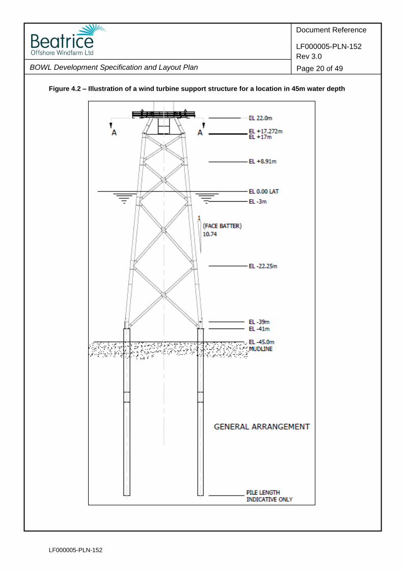
4.2.15 The jacket substructures range in overall height from 57m up to 77m to take account
of variable water depths across the site, and they each have a footprint measuring 24m
by 24m. Figure 4.2 below shows the general design and arrangement of a wind turbine
support structure for a location in 45m water depth, which is representative of depths
encountered across the Wind Farm site. Whilst the structures will vary slightly in height
to allow for water depth, their design and arrangement will otherwise not alter. The
height of the structures above the surface of the sea will be consistent across the site
at 22 m above lowest astronomical tide (LAT).
LF000005-PLN-152
BOWL Development Specification and Layout Plan
Document Reference
LF000005-PLN-152
Rev 3.0
Page 20 of 49
Figure 4.2 – Illustration of a wind turbine support structure for a location in 45m water depth
LF000005-PLN-152
BOWL Development Specification and Layout Plan
Document Reference
LF000005-PLN-152
Rev 3.0
Page 21 of 49
Wind Farm Bathymetry and Seabed Conditions
4.2.17 Bathymetry across the Wind Farm ranges from 35m below Lowest Astronomical Tide
(LAT) in the south-west corner up to 68m in the northwest-corner (see Figure 4.1).
There is a gentle slope of around 0.5° along the length of the site.
4.2.18 The wind turbines will be installed in water depths ranging from 38.0m to 54.9m below
LAT. Nearly two-thirds of the wind turbines will be installed in depths between 40.0m
and 50.0m below LAT; the remaining wind turbines being installed at locations divided
more or less equally between the limits of the range. Water depths at each wind turbine
location are listed in Table 4.1 below.
4.2.19 During construction, pile foundation and jacket substructure installation will be phased
across five ‘clusters’ within the Wind Farm. The clusters have been defined on the
basis of their depth range. Further information on the phasing of installation across
clusters is presented in the Piling Strategy (PS) (LF000005-PLN-142).
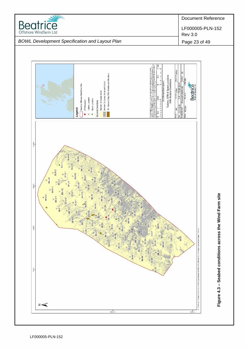
4.2.20 Seabed sedimentary conditions across the Wind Farm are characterised in general as
being comprised of loose to very dense sand with occasional beds of gravel. Boulders
of ~1m diameter or greater are rare based on the most recent analysis of geophysical
and geotechnical information. Seabed sediments are shown in Figure 4.3.
Key Constraints
4.2.21 There are a small number of physical spatial constraints within the Wind Farm
‘developable area’. Infrastructure within the array avoids the following constraints, as
shown in Figure 4.4:
A single plugged and abandoned wellhead;
Several features of potential archaeological interest, identified by geophysical survey, and their associated Archaeological Exclusion Zones (AEZs).
4.2.22 A review of AEZs was carried out in October 2015 following completion of a ground
truthing survey in July 2015 to investigate potential archaeological interests. Following
consultation with Historic Scotland three AEZs were removed from the wind farm site
in light of the evidence presented in the review. These AEZs have been removed from
Figure 4.4.
4.2.23 The following constraints have been taken into account in defining the Wind Farm
‘developable area’ boundaries, and are also shown on Figure 4.4:
A 2.5km buffer zone around the Beatrice Alpha, Bravo, Charlie and Jacky oil platforms to preclude the construction of any wind turbines, offshore substations or meteorological masts and a 500m buffer around the same platforms precluding the installation of any cables (as required by conditions of the S36 Consent and Marine Licences);
A 100m buffer from the site lease boundary (as required under the terms of
LF000005-PLN-152
BOWL Development Specification and Layout Plan
Document Reference
LF000005-PLN-152
Rev 3.0
Page 22 of 49
the Crown Estate Agreement for Lease);
A 770m buffer from the Moray Firth Round 3 Zone boundary (as required under the terms of the Crown Estate Agreement for Lease) applies to all cables within the Wind Farm boundary; and
An avoidance of water depths in excess of 55m below LAT (for reasons of BOWL engineering feasibility).
4.2.24 A series of environmental baseline surveys have been commissioned by BOWL to
understand environmental conditions across the Wind Farm site and to identify any
environmental sensitivities. Surveys have not identified any environmental sensitivities
relevant to determination of the final Wind Farm layout.
LF000005-PLN-152
BOWL Development Specification and Layout Plan
Document Reference
LF000005-PLN-152
Rev 3.0
Page 23 of 49
Fig
ure
4.3
– S
eab
ed
co
nd
itio
ns a
cro
ss t
he W
ind
Fa
rm s
ite

LF000005-PLN-152
BOWL Development Specification and Layout Plan
Document Reference
LF000005-PLN-152
Rev 3.0
Page 24 of 49
Fig
ure
4.4
– K
ey c
on
str
ain
ts t
o t
he W
ind
Farm
dev
elo
pab
le a
rea
LF000005-PLN-152
BOWL Development Specification and Layout Plan
Document Reference
LF000005-PLN-152
Rev 3.0
Page 25 of 49
4.3 Co-ordinates for Wind Turbine Locations
4.3.1 S36 Consent Condition 13 requires that this DSLP include the following:
A list of latitude and longitude co-ordinates accurate to three decimal places of minutes for each WTG, this should also be provided as a GIS shape file using WGS84 format;
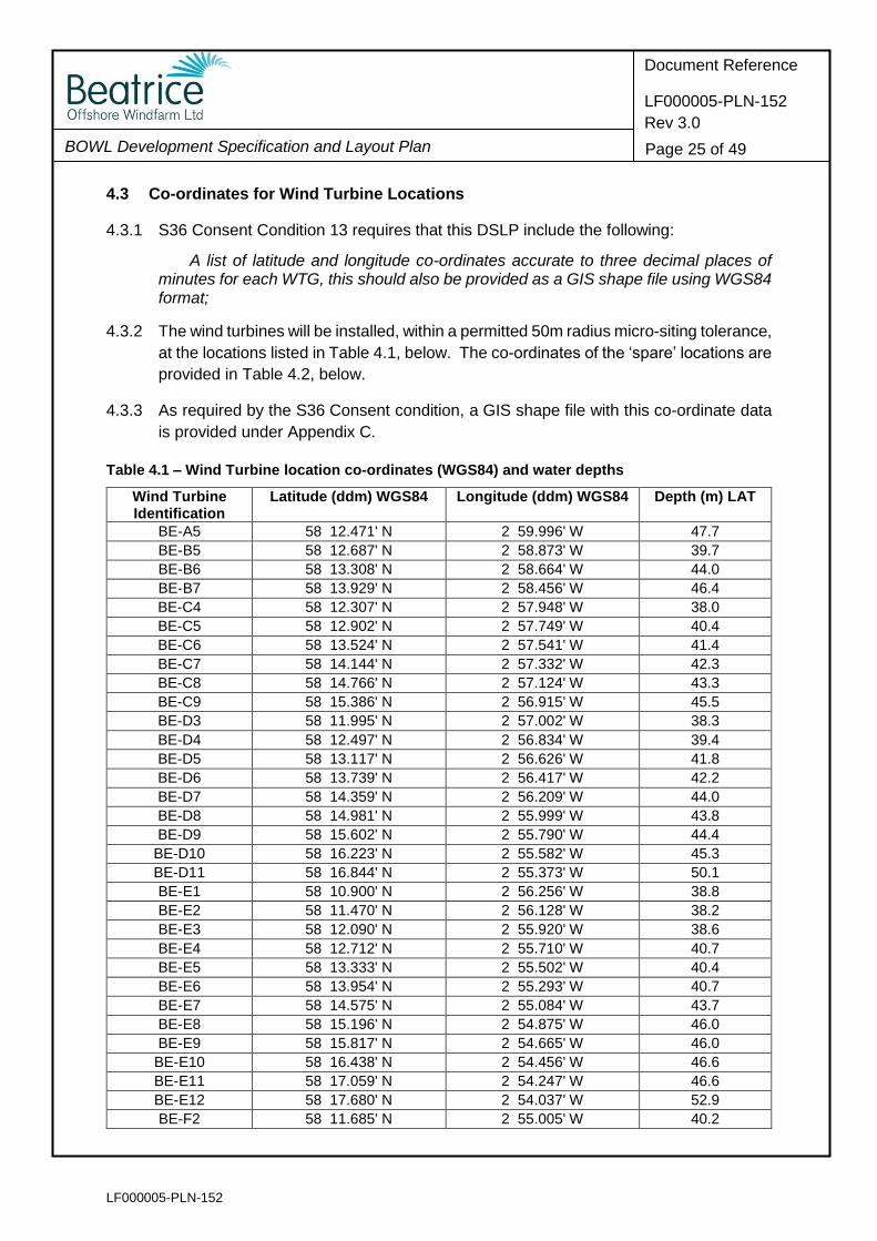
4.3.2 The wind turbines will be installed, within a permitted 50m radius micro-siting tolerance,
at the locations listed in Table 4.1, below. The co-ordinates of the ‘spare’ locations are
provided in Table 4.2, below.
4.3.3 As required by the S36 Consent condition, a GIS shape file with this co-ordinate data
is provided under Appendix C.
Table 4.1 – Wind Turbine location co-ordinates (WGS84) and water depths
Wind Turbine Identification
Latitude (ddm) WGS84 Longitude (ddm) WGS84 Depth (m) LAT
BE-A5 58 12.471' N 2 59.996' W 47.7
BE-B5 58 12.687' N 2 58.873' W 39.7
BE-B6 58 13.308' N 2 58.664' W 44.0
BE-B7 58 13.929' N 2 58.456' W 46.4
BE-C4 58 12.307' N 2 57.948' W 38.0
BE-C5 58 12.902' N 2 57.749' W 40.4
BE-C6 58 13.524' N 2 57.541' W 41.4
BE-C7 58 14.144' N 2 57.332' W 42.3
BE-C8 58 14.766' N 2 57.124' W 43.3
BE-C9 58 15.386' N 2 56.915' W 45.5
BE-D3 58 11.995' N 2 57.002' W 38.3
BE-D4 58 12.497' N 2 56.834' W 39.4
BE-D5 58 13.117' N 2 56.626' W 41.8
BE-D6 58 13.739' N 2 56.417' W 42.2
BE-D7 58 14.359' N 2 56.209' W 44.0
BE-D8 58 14.981' N 2 55.999' W 43.8
BE-D9 58 15.602' N 2 55.790' W 44.4
BE-D10 58 16.223' N 2 55.582' W 45.3
BE-D11 58 16.844' N 2 55.373' W 50.1
BE-E1 58 10.900' N 2 56.256' W 38.8
BE-E2 58 11.470' N 2 56.128' W 38.2
BE-E3 58 12.090' N 2 55.920' W 38.6
BE-E4 58 12.712' N 2 55.710' W 40.7
BE-E5 58 13.333' N 2 55.502' W 40.4
BE-E6 58 13.954' N 2 55.293' W 40.7
BE-E7 58 14.575' N 2 55.084' W 43.7
BE-E8 58 15.196' N 2 54.875' W 46.0
BE-E9 58 15.817' N 2 54.665' W 46.0
BE-E10 58 16.438' N 2 54.456' W 46.6
BE-E11 58 17.059' N 2 54.247' W 46.6
BE-E12 58 17.680' N 2 54.037' W 52.9
BE-F2 58 11.685' N 2 55.005' W 40.2

LF000005-PLN-152
BOWL Development Specification and Layout Plan
Document Reference
LF000005-PLN-152
Rev 3.0
Page 26 of 49
Wind Turbine Identification
Latitude (ddm) WGS84 Longitude (ddm) WGS84 Depth (m) LAT
BE-F3 58 12.306' N 2 54.796' W 38.7
BE-F4 58 12.927' N 2 54.588' W 40.4
BE-F5 58 13.548' N 2 54.378' W 39.7
BE-F6 58 14.168' N 2 54.169' W 41.6
BE-F9 58 16.031' N 2 53.540' W 49.0
BE-F10 58 16.653' N 2 53.330' W 48.2
BE-F11 58 17.274' N 2 53.120' W 48.8
BE-F12 58 17.894' N 2 52.911' W 48.6
BE-F13 58 18.516' N 2 52.701' W 54.2
BE-G3 58 12.544' N 2 53.726' W 40.5
BE-G4 58 13.142' N 2 53.464' W 38.6
BE-G5 58 13.762' N 2 53.254' W 39.7
BE-G6 58 14.384' N 2 53.044' W 40.2
BE-G8 58 15.625' N 2 52.625' W 45.2
BE-G9 58 16.247' N 2 52.415' W 49.9
BE-G10 58 16.867' N 2 52.204' W 49.4
BE-G11 58 17.488' N 2 51.994' W 51.1
BE-G12 58 18.109' N 2 51.784' W 50.5
BE-G13 58 18.730' N 2 51.574' W 53.4
BE-G14 58 19.351' N 2 51.362' W 54.9
BE-H4 58 13.356' N 2 52.339' W 41.1
BE-H5 58 13.977' N 2 52.130' W 41.9
BE-H6 58 14.598' N 2 51.920' W 40.0
BE-H7 58 15.219' N 2 51.709' W 42.5
BE-H8 58 15.840' N 2 51.499' W 44.2
BE-H9 58 16.461' N 2 51.289' W 47.8
BE-H10 58 17.082' N 2 51.079' W 49.6
BE-H11 58 17.703' N 2 50.867' W 50.2
BE-H12 58 18.324' N 2 50.657' W 51.8
BE-H13 58 18.944' N 2 50.446' W 53.4
BE-J5 58 14.192' N 2 51.005' W 41.4
BE-J6 58 14.812' N 2 50.795' W 41.5
BE-J7 58 15.433' N 2 50.585' W 42.7
BE-J8 58 16.055' N 2 50.373' W 45.5
BE-J9 58 16.675' N 2 50.163' W 47.8
BE-J10 58 17.296' N 2 49.952' W 49.5
BE-J11 58 17.917' N 2 49.741' W 50.8
BE-J12 58 18.538' N 2 49.530' W 52.2
BE-J13 58 19.159' N 2 49.319' W 54.2
BE-K6 58 15.027' N 2 49.669' W 44.6
BE-K7 58 15.648' N 2 49.459' W 44.3
BE-K8 58 16.269' N 2 49.247' W 47.6
BE-K9 58 16.890' N 2 49.036' W 48.6
BE-K10 58 17.510' N 2 48.825' W 51.5
BE-K11 58 18.131' N 2 48.614' W 52.0
BE-K12 58 18.752' N 2 48.403' W 53.1
BE-L7 58 15.862' N 2 48.333' W 44.5
BE-L8 58 16.482' N 2 48.122' W 47.8
LF000005-PLN-152
BOWL Development Specification and Layout Plan
Document Reference
LF000005-PLN-152
Rev 3.0
Page 27 of 49
Wind Turbine Identification
Latitude (ddm) WGS84 Longitude (ddm) WGS84 Depth (m) LAT
BE-L9 58 17.104' N 2 47.910' W 49.4
BE-L10 58 17.724' N 2 47.698' W 49.6
BE-M9 58 17.317' N 2 46.784' W 49.0
BE-M10 58 17.938' N 2 46.571' W 49.9
Table 4.2 – Spare location co-ordinates (WGS84) and water depths
Spare Location Identification
Latitude (ddm) WGS84 Longitude (ddm) WGS84 Depth (m) LAT
BE-F7 58 14.790' N 2 53.959' W 42.5
BE-L11 58 18.345' N 2 47.487' W 52.4
4.4 Wind Turbine Dimensions
4.4.1 S36 Consent Condition 13 requires that this DSLP includes the following:
A table or diagram of each WTG dimensions including height to blade tip (measured above HAT), height to hub (measured above HAT to the centreline of the generator shaft), rotor diameter and rotation speed;
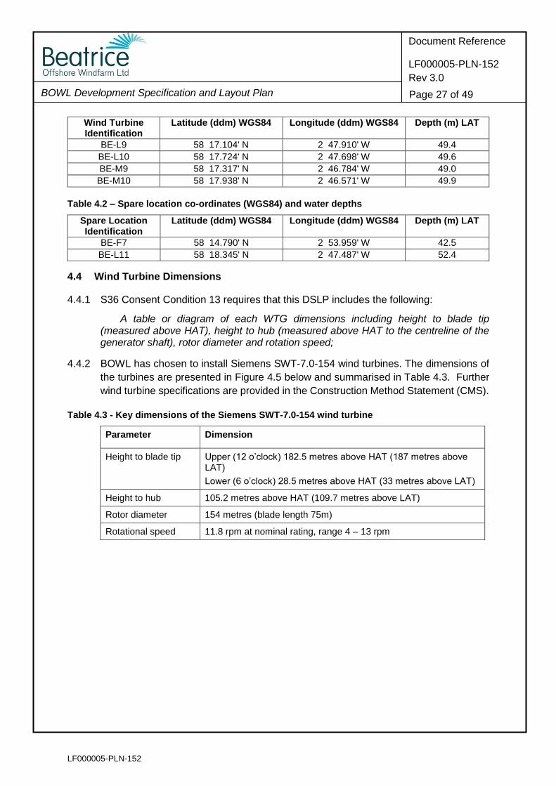
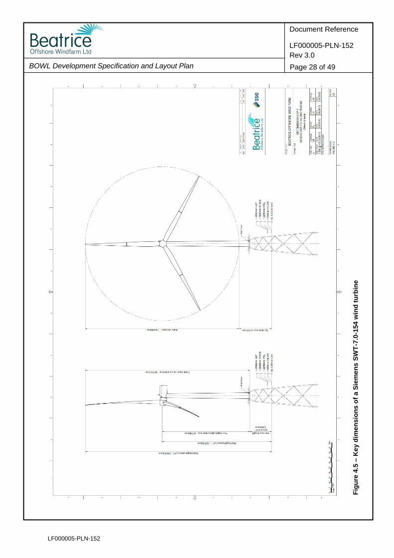
4.4.2 BOWL has chosen to install Siemens SWT-7.0-154 wind turbines. The dimensions of
the turbines are presented in Figure 4.5 below and summarised in Table 4.3. Further
wind turbine specifications are provided in the Construction Method Statement (CMS).
Table 4.3 - Key dimensions of the Siemens SWT-7.0-154 wind turbine
Parameter Dimension
Height to blade tip Upper (12 o’clock) 182.5 metres above HAT (187 metres above LAT)
Lower (6 o’clock) 28.5 metres above HAT (33 metres above LAT)
Height to hub 105.2 metres above HAT (109.7 metres above LAT)
Rotor diameter 154 metres (blade length 75m)
Rotational speed 11.8 rpm at nominal rating, range 4 – 13 rpm
LF000005-PLN-152
BOWL Development Specification and Layout Plan
Document Reference
LF000005-PLN-152
Rev 3.0
Page 28 of 49
Fig
ure
4.5
– K
ey d
imen
sio
ns o
f a S
iem
en
s S
WT
-7.0
-154 w
ind
tu
rbin
e
LF000005-PLN-152
BOWL Development Specification and Layout Plan
Document Reference
LF000005-PLN-152
Rev 3.0
Page 29 of 49
4.5 Generating Capacity
4.5.1 S36 Consent Condition 13 requires that this DSLP include the following:
The generating capacity of each WTG used on the Site and a confirmed generating capacity for the Site overall;
4.5.2 The chosen wind turbine for installation at the Beatrice Offshore Wind Farm is the
Siemens SWT-7.0-154. Each of the wind turbines will have a generating capacity of
7MW.
4.5.3 The total generating capacity of the wind farm will be 588MW.
4.6 Wind Turbine Finishes
4.6.1 S36 Consent Condition 13 requires that this DSLP include the following:
The finishes for each WTG (see condition 20 on WTG lighting and marking); and
4.6.2 Each wind turbine (tower sections, nacelle and blades) will be finished in the standard
light grey, RAL 7035. The turbine rotor blades will have blade hover reference
markings (red marks painted at 10, 20 and 30 metres from the hub) of at least 60cm
width (to assist SAR helicopter operations).
4.6.3 The heli-hoist platform on top of the wind turbine nacelle will be finished in traffic red
RAL 3020.
4.6.4 The jacket substructure and transition piece will be finished in golden yellow RAL 1004
from 2m below LAT up to the interface point at 22m above LAT.
4.7 Inter-Array Cable Arrangement and Lengths
4.7.1 S36 Consent Condition 13 requires that this DSLP include the following:
The length and proposed arrangements on the seabed of all inter-array cables.
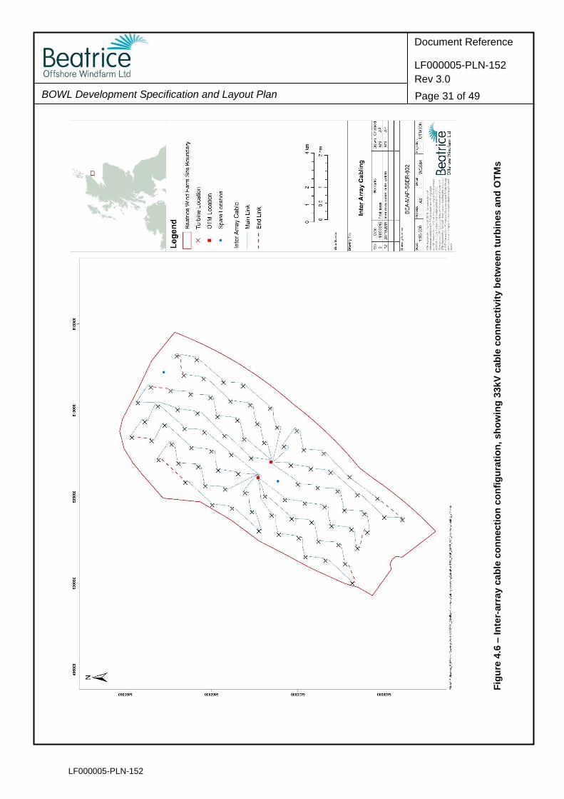
4.7.2 The wind turbines are connected at a voltage of 33kV by inter-array cabling in ‘strings’.
There are fourteen strings and six wind turbines per string. The first wind turbine in a
string is connected by an inter-array cable to an OTM. The strings are cross-connected
at the ends in pairs. These cross connections are to provide auxiliary power to the
string in the event of an outage on a string.
4.7.3 There will be a total of 91 inter-array cables, of two different sizes (two sizes of cable
are used to allow for tapering of cable capacity away from the OTMs), installed across
the Wind Farm as follows:
28 lengths of Type 1 cable (indicatively 630mm2 cores and a total cable outer diameter of 147mm);
63 lengths of Type 2 cable (indicatively 300mm2 cores and a total cable outer diameter of 123mm).

LF000005-PLN-152
BOWL Development Specification and Layout Plan
Document Reference
LF000005-PLN-152
Rev 3.0
Page 30 of 49
4.7.4 In addition there is a single 220kV inter-connector cable that connects the two OTMs
and allows power to be exported should one of the two export cables be unavailable.
4.7.5 The arrangement of the cables between the wind turbines and the connections to the
OTMs is set out in Figure 4.6.
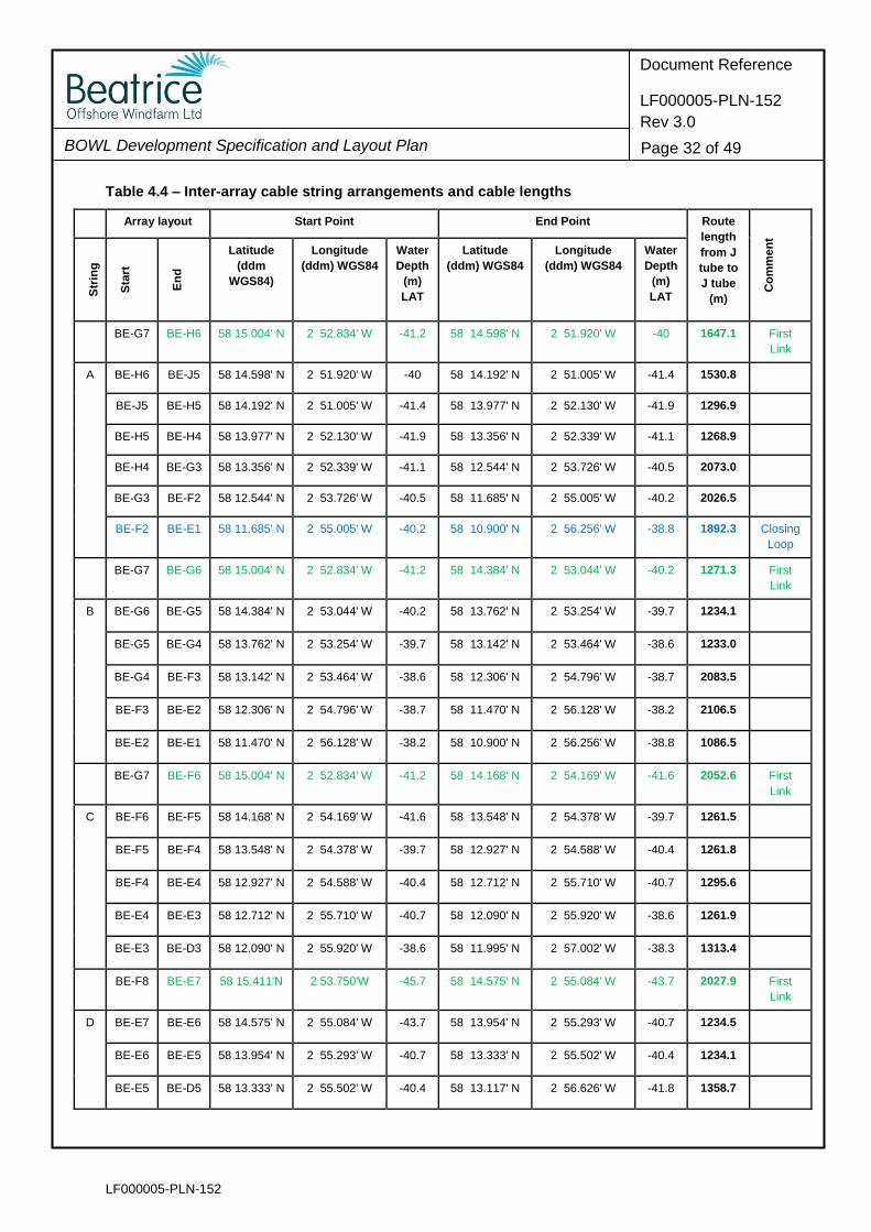
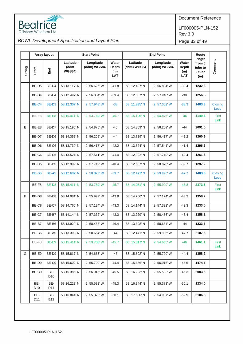
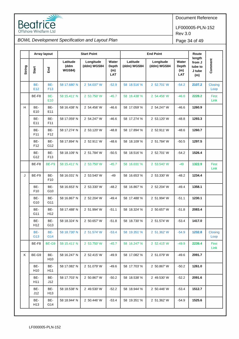
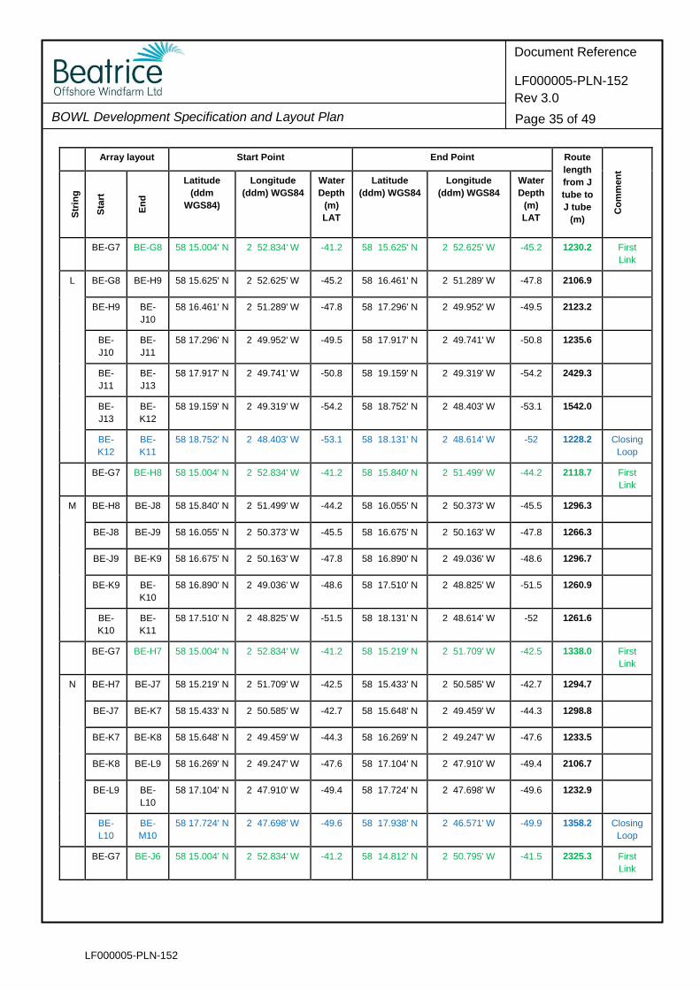
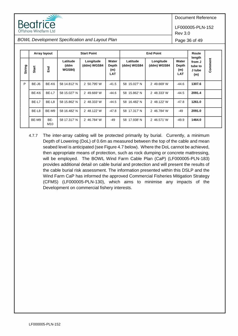
4.7.6 The lengths of each of the inter-array cables between the turbines and OTM locations
(where relevant) are presented in Table 4.4. The total length of the inter-array cabling
to be installed on the seabed is140km. .
LF000005-PLN-152
BOWL Development Specification and Layout Plan
Document Reference
LF000005-PLN-152
Rev 3.0
Page 31 of 49
Fig
ure
4.6
– In
ter-
arr
ay
ca
ble
co
nn
ecti
on
co
nfi
gu
rati
on
, sh
ow
ing
33kV
cab
le c
on
necti
vit
y b
etw
een
tu
rbin
es a
nd
OT
Ms
LF000005-PLN-152
BOWL Development Specification and Layout Plan
Document Reference
LF000005-PLN-152
Rev 3.0
Page 32 of 49
Table 4.4 – Inter-array cable string arrangements and cable lengths
Array layout Start Point End Point Route
length
from J
tube to
J tube
(m)
Co
mm
en
t
Str
ing
Sta
rt
En
d
Latitude
(ddm
WGS84)
Longitude
(ddm) WGS84
Water
Depth
(m)
LAT
Latitude
(ddm) WGS84
Longitude
(ddm) WGS84
Water
Depth
(m)
LAT
BE-G7 BE-H6 58 15.004' N 2 52.834' W -41.2 58 14.598' N 2 51.920' W -40 1647.1 First
Link
A BE-H6 BE-J5 58 14.598' N 2 51.920' W -40 58 14.192' N 2 51.005' W -41.4 1530.8
BE-J5 BE-H5 58 14.192' N 2 51.005' W -41.4 58 13.977' N 2 52.130' W -41.9 1296.9
BE-H5 BE-H4 58 13.977' N 2 52.130' W -41.9 58 13.356' N 2 52.339' W -41.1 1268.9
BE-H4 BE-G3 58 13.356' N 2 52.339' W -41.1 58 12.544' N 2 53.726' W -40.5 2073.0
BE-G3 BE-F2 58 12.544' N 2 53.726' W -40.5 58 11.685' N 2 55.005' W -40.2 2026.5
BE-F2 BE-E1 58 11.685' N 2 55.005' W -40.2 58 10.900' N 2 56.256' W -38.8 1892.3 Closing
Loop
BE-G7 BE-G6 58 15.004' N 2 52.834' W -41.2 58 14.384' N 2 53.044' W -40.2 1271.3 First
Link
B BE-G6 BE-G5 58 14.384' N 2 53.044' W -40.2 58 13.762' N 2 53.254' W -39.7 1234.1
BE-G5 BE-G4 58 13.762' N 2 53.254' W -39.7 58 13.142' N 2 53.464' W -38.6 1233.0
BE-G4 BE-F3 58 13.142' N 2 53.464' W -38.6 58 12.306' N 2 54.796' W -38.7 2083.5
BE-F3 BE-E2 58 12.306' N 2 54.796' W -38.7 58 11.470' N 2 56.128' W -38.2 2106.5
BE-E2 BE-E1 58 11.470' N 2 56.128' W -38.2 58 10.900' N 2 56.256' W -38.8 1086.5
BE-G7 BE-F6 58 15.004' N 2 52.834' W -41.2 58 14.168' N 2 54.169' W -41.6 2052.6 First
Link
C BE-F6 BE-F5 58 14.168' N 2 54.169' W -41.6 58 13.548' N 2 54.378' W -39.7 1261.5
BE-F5 BE-F4 58 13.548' N 2 54.378' W -39.7 58 12.927' N 2 54.588' W -40.4 1261.8
BE-F4 BE-E4 58 12.927' N 2 54.588' W -40.4 58 12.712' N 2 55.710' W -40.7 1295.6
BE-E4 BE-E3 58 12.712' N 2 55.710' W -40.7 58 12.090' N 2 55.920' W -38.6 1261.9
BE-E3 BE-D3 58 12.090' N 2 55.920' W -38.6 58 11.995' N 2 57.002' W -38.3 1313.4
BE-F8 BE-E7 58 15.411'N 2 53.750'W -45.7 58 14.575' N 2 55.084' W -43.7 2027.9 First
Link
D BE-E7 BE-E6 58 14.575' N 2 55.084' W -43.7 58 13.954' N 2 55.293' W -40.7 1234.5
BE-E6 BE-E5 58 13.954' N 2 55.293' W -40.7 58 13.333' N 2 55.502' W -40.4 1234.1
BE-E5 BE-D5 58 13.333' N 2 55.502' W -40.4 58 13.117' N 2 56.626' W -41.8 1358.7
LF000005-PLN-152
BOWL Development Specification and Layout Plan
Document Reference
LF000005-PLN-152
Rev 3.0
Page 33 of 49
Array layout Start Point End Point Route
length
from J
tube to
J tube
(m)
Co
mm
en
t
Str
ing
Sta
rt
En
d
Latitude
(ddm
WGS84)
Longitude
(ddm) WGS84
Water
Depth
(m)
LAT
Latitude
(ddm) WGS84
Longitude
(ddm) WGS84
Water
Depth
(m)
LAT
BE-D5 BE-D4 58 13.117' N 2 56.626' W -41.8 58 12.497' N 2 56.834' W -39.4 1232.3
BE-D4 BE-C4 58 12.497' N 2 56.834' W -39.4 58 12.307' N 2 57.948' W -38 1256.5
BE-C4 BE-D3 58 12.307' N 2 57.948' W -38 58 11.995' N 2 57.002' W -38.3 1483.3 Closing
Loop
BE-F8 BE-E8 58 15.411' N 2 53.750' W -45.7 58 15.196' N 2 54.875' W -46 1149.8 First
Link
E BE-E8 BE-D7 58 15.196' N 2 54.875' W -46 58 14.359' N 2 56.209' W -44 2091.5
BE-D7 BE-D6 58 14.359' N 2 56.209' W -44 58 13.739' N 2 56.417' W -42.2 1260.9
BE-D6 BE-C6 58 13.739' N 2 56.417' W -42.2 58 13.524' N 2 57.541' W -41.4 1296.6
BE-C6 BE-C5 58 13.524' N 2 57.541' W -41.4 58 12.902' N 2 57.749' W -40.4 1261.6
BE-C5 BE-B5 58 12.902' N 2 57.749' W -40.4 58 12.687' N 2 58.873' W -39.7 1297.2
BE-B5 BE-A5 58 12.687' N 2 58.873' W -39.7 58 12.471' N 2 59.996' W -47.7 1483.6 Closing
Loop
BE-F8 BE-D8 58 15.411' N 2 53.750' W -45.7 58 14.981' N 2 55.999' W -43.8 2373.8 First
Link
F BE-D8 BE-C8 58 14.981' N 2 55.999' W -43.8 58 14.766' N 2 57.124' W -43.3 1358.2
BE-C8 BE-C7 58 14.766' N 2 57.124' W -43.3 58 14.144' N 2 57.332' W -42.3 1233.5
BE-C7 BE-B7 58 14.144' N 2 57.332' W -42.3 58 13.929' N 2 58.456' W -46.4 1358.1
BE-B7 BE-B6 58 13.929' N 2 58.456' W -46.4 58 13.308' N 2 58.664' W -44 1233.5
BE-B6 BE-A5 58 13.308' N 2 58.664' W -44 58 12.471' N 2 59.996' W -47.7 2107.6
BE-F8 BE-E9 58 15.411' N 2 53.750' W -45.7 58 15.817' N 2 54.665' W -46 1461.1 First
Link
G BE-E9 BE-D9 58 15.817' N 2 54.665' W -46 58 15.602' N 2 55.790' W -44.4 1358.2
BE-D9 BE-C9 58 15.602' N 2 55.790' W -44.4 58 15.386' N 2 56.915' W -45.5 1474.5
BE-C9 BE-
D10
58 15.386' N 2 56.915' W -45.5 58 16.223' N 2 55.582' W -45.3 2083.6
BE-
D10
BE-
D11
58 16.223' N 2 55.582' W -45.3 58 16.844' N 2 55.373' W -50.1 1234.0
BE-
D11
BE-
E12
58 16.844' N 2 55.373' W -50.1 58 17.680' N 2 54.037' W -52.9 2106.8
LF000005-PLN-152
BOWL Development Specification and Layout Plan
Document Reference
LF000005-PLN-152
Rev 3.0
Page 34 of 49
Array layout Start Point End Point Route
length
from J
tube to
J tube
(m)
Co
mm
en
t
Str
ing
Sta
rt
En
d
Latitude
(ddm
WGS84)
Longitude
(ddm) WGS84
Water
Depth
(m)
LAT
Latitude
(ddm) WGS84
Longitude
(ddm) WGS84
Water
Depth
(m)
LAT
BE-
E12
BE-
F13
58 17.680' N 2 54.037' W -52.9 58 18.516' N 2 52.701' W -54.2 2107.2 Closing
Loop
BE-F8 BE-
E10
58 15.411' N 2 53.750' W -45.7 58 16.438' N 2 54.456' W -46.6 2228.2 First
Link
H BE-
E10
BE-
E11
58 16.438' N 2 54.456' W -46.6 58 17.059' N 2 54.247' W -46.6 1260.9
BE-
E11
BE-
F11
58 17.059' N 2 54.247' W -46.6 58 17.274' N 2 53.120' W -48.8 1293.3
BE-
F11
BE-
F12
58 17.274' N 2 53.120' W -48.8 58 17.894' N 2 52.911' W -48.6 1260.7
BE-
F12
BE-
G12
58 17.894' N 2 52.911' W -48.6 58 18.109' N 2 51.784' W -50.5 1297.5
BE-
G12
BE-
F13
58 18.109' N 2 51.784' W -50.5 58 18.516' N 2 52.701' W -54.2 1526.4
BE-F8 BE-F9 58 15.411' N 2 53.750' W -45.7 58 16.031' N 2 53.540' W -49 1322.9 First
Link
J BE-F9 BE-
F10
58 16.031' N 2 53.540' W -49 58 16.653' N 2 53.330' W -48.2 1234.4
BE-
F10
BE-
G10
58 16.653' N 2 53.330' W -48.2 58 16.867' N 2 52.204' W -49.4 1358.1
BE-
G10
BE-
G11
58 16.867' N 2 52.204' W -49.4 58 17.488' N 2 51.994' W -51.1 1230.1
BE-
G11
BE-
H12
58 17.488' N 2 51.994' W -51.1 58 18.324' N 2 50.657' W -51.8 2083.4
BE-
H12
BE-
G13
58 18.324' N 2 50.657' W -51.8 58 18.730' N 2 51.574' W -53.4 1417.0
BE-
G13
BE-
G14
58 18.730' N 2 51.574' W -53.4 58 19.351' N 2 51.362' W -54.9 1232.8 Closing
Loop
BE-F8 BE-G9 58 15.411' N 2 53.750' W -45.7 58 16.247' N 2 52.415' W -49.9 2239.4 First
Link
K BE-G9 BE-
H10
58 16.247' N 2 52.415' W -49.9 58 17.082' N 2 51.079' W -49.6 2091.7
BE-
H10
BE-
H11
58 17.082' N 2 51.079' W -49.6 58 17.703' N 2 50.867' W -50.2 1261.0
BE-
H11
BE-
J12
58 17.703' N 2 50.867' W -50.2 58 18.538' N 2 49.530' W -52.2 2091.6
BE-
J12
BE-
H13
58 18.538' N 2 49.530' W -52.2 58 18.944' N 2 50.446' W -53.4 1512.7
BE-
H13
BE-
G14
58 18.944' N 2 50.446' W -53.4 58 19.351' N 2 51.362' W -54.9 1525.6
LF000005-PLN-152
BOWL Development Specification and Layout Plan
Document Reference
LF000005-PLN-152
Rev 3.0
Page 35 of 49
Array layout Start Point End Point Route
length
from J
tube to
J tube
(m)
Co
mm
en
t
Str
ing
Sta
rt
En
d
Latitude
(ddm
WGS84)
Longitude
(ddm) WGS84
Water
Depth
(m)
LAT
Latitude
(ddm) WGS84
Longitude
(ddm) WGS84
Water
Depth
(m)
LAT
BE-G7 BE-G8 58 15.004' N 2 52.834' W -41.2 58 15.625' N 2 52.625' W -45.2 1230.2 First
Link
L BE-G8 BE-H9 58 15.625' N 2 52.625' W -45.2 58 16.461' N 2 51.289' W -47.8 2106.9
BE-H9 BE-
J10
58 16.461' N 2 51.289' W -47.8 58 17.296' N 2 49.952' W -49.5 2123.2
BE-
J10
BE-
J11
58 17.296' N 2 49.952' W -49.5 58 17.917' N 2 49.741' W -50.8 1235.6
BE-
J11
BE-
J13
58 17.917' N 2 49.741' W -50.8 58 19.159' N 2 49.319' W -54.2 2429.3
BE-
J13
BE-
K12
58 19.159' N 2 49.319' W -54.2 58 18.752' N 2 48.403' W -53.1 1542.0
BE-
K12
BE-
K11
58 18.752' N 2 48.403' W -53.1 58 18.131' N 2 48.614' W -52 1228.2 Closing
Loop
BE-G7 BE-H8 58 15.004' N 2 52.834' W -41.2 58 15.840' N 2 51.499' W -44.2 2118.7 First
Link
M BE-H8 BE-J8 58 15.840' N 2 51.499' W -44.2 58 16.055' N 2 50.373' W -45.5 1296.3
BE-J8 BE-J9 58 16.055' N 2 50.373' W -45.5 58 16.675' N 2 50.163' W -47.8 1266.3
BE-J9 BE-K9 58 16.675' N 2 50.163' W -47.8 58 16.890' N 2 49.036' W -48.6 1296.7
BE-K9 BE-
K10
58 16.890' N 2 49.036' W -48.6 58 17.510' N 2 48.825' W -51.5 1260.9
BE-
K10
BE-
K11
58 17.510' N 2 48.825' W -51.5 58 18.131' N 2 48.614' W -52 1261.6
BE-G7 BE-H7 58 15.004' N 2 52.834' W -41.2 58 15.219' N 2 51.709' W -42.5 1338.0 First
Link
N BE-H7 BE-J7 58 15.219' N 2 51.709' W -42.5 58 15.433' N 2 50.585' W -42.7 1294.7
BE-J7 BE-K7 58 15.433' N 2 50.585' W -42.7 58 15.648' N 2 49.459' W -44.3 1298.8
BE-K7 BE-K8 58 15.648' N 2 49.459' W -44.3 58 16.269' N 2 49.247' W -47.6 1233.5
BE-K8 BE-L9 58 16.269' N 2 49.247' W -47.6 58 17.104' N 2 47.910' W -49.4 2106.7
BE-L9 BE-
L10
58 17.104' N 2 47.910' W -49.4 58 17.724' N 2 47.698' W -49.6 1232.9
BE-
L10
BE-
M10
58 17.724' N 2 47.698' W -49.6 58 17.938' N 2 46.571' W -49.9 1358.2 Closing
Loop
BE-G7 BE-J6 58 15.004' N 2 52.834' W -41.2 58 14.812' N 2 50.795' W -41.5 2325.3 First
Link
LF000005-PLN-152
BOWL Development Specification and Layout Plan
Document Reference
LF000005-PLN-152
Rev 3.0
Page 36 of 49
Array layout Start Point End Point Route
length
from J
tube to
J tube
(m)
Co
mm
en
t
Str
ing
Sta
rt
En
d
Latitude
(ddm
WGS84)
Longitude
(ddm) WGS84
Water
Depth
(m)
LAT
Latitude
(ddm) WGS84
Longitude
(ddm) WGS84
Water
Depth
(m)
LAT
P BE-J6 BE-K6 58 14.812' N 2 50.795' W -41.5 58 15.027' N 2 49.669' W -44.6 1307.6
BE-K6 BE-L7 58 15.027' N 2 49.669' W -44.6 58 15.862' N 2 48.333' W -44.5 2091.4
BE-L7 BE-L8 58 15.862' N 2 48.333' W -44.5 58 16.482' N 2 48.122' W -47.8 1261.0
BE-L8 BE-M9 58 16.482' N 2 48.122' W -47.8 58 17.317' N 2 46.784' W -49 2091.0
BE-M9 BE-
M10
58 17.317' N 2 46.784' W -49 58 17.938' N 2 46.571' W -49.9 1464.0
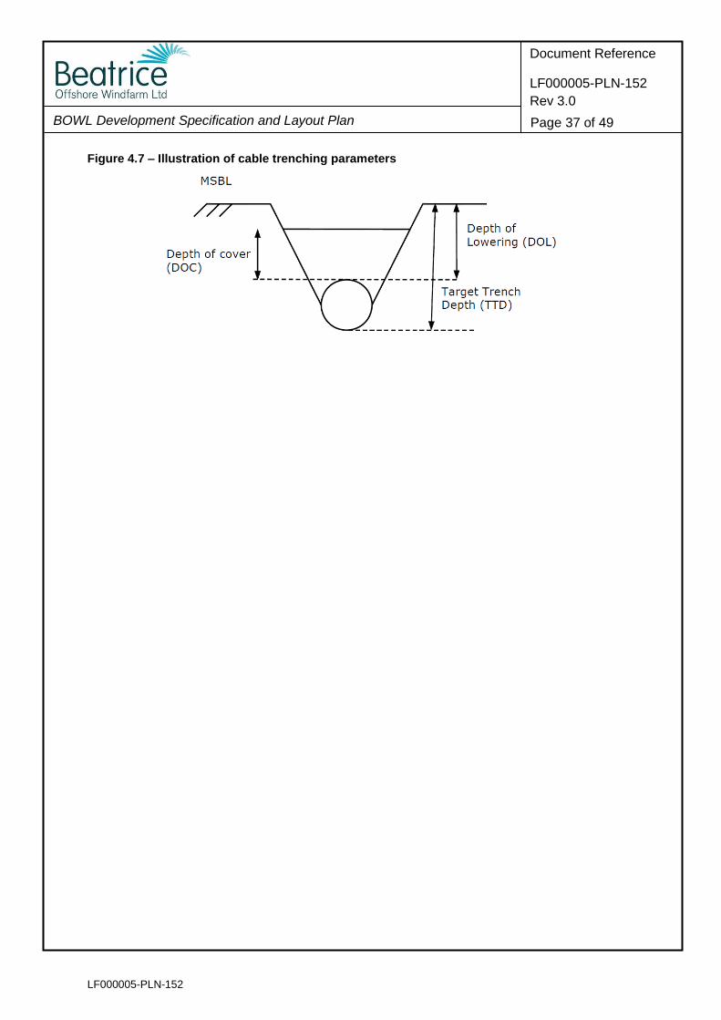
4.7.7 The inter-array cabling will be protected primarily by burial. Currently, a minimum
Depth of Lowering (DoL) of 0.6m as measured between the top of the cable and mean
seabed level is anticipated (see Figure 4.7 below). Where the DoL cannot be achieved,
then appropriate means of protection, such as rock dumping or concrete mattressing,
will be employed. The BOWL Wind Farm Cable Plan (CaP) (LF000005-PLN-183)
provides additional detail on cable burial and protection and will present the results of
the cable burial risk assessment. The information presented within this DSLP and the
Wind Farm CaP has informed the approved Commercial Fisheries Mitigation Strategy
(CFMS) (LF000005-PLN-130), which aims to minimise any impacts of the
Development on commercial fishery interests.
LF000005-PLN-152
BOWL Development Specification and Layout Plan
Document Reference
LF000005-PLN-152
Rev 3.0
Page 37 of 49
Figure 4.7 – Illustration of cable trenching parameters
LF000005-PLN-152
BOWL Development Specification and Layout Plan
Document Reference
LF000005-PLN-152
Rev 3.0
Page 38 of 49
5 Design, Specification and Layout – Offshore Transformer Modules
5.1 Introduction
5.1.1 This section of the DSLP details the OTM design and layout specification as required
by the OfTW Marine Licence condition 3.2.2.6 detailed in Table 1.1.
5.2 Offshore Transformer Modules Layout and Specification
5.2.1 OfTW Marine Licence Consent Condition 3.2.2.6 requires that this DSLP include the
following:
A plan showing the proposed location of each individual OSP, seabed conditions, bathymetry, confirmed foundation type for each OSP and any key constraints recorded on the Site;
5.2.2 The Wind Farm layout presented in Figure 4.1 above includes the location of the two
OTMs. The two OTMs are located close to the geometric centre of the site.
OTM Foundation Types
5.2.3 Each OTM is supported by a tubular jacket substructure and piled foundations. To
encourage efficiencies and make best use of project assets, such as the pile
installation template, the jackets are as per those used for the wind turbines and as
described in Section 4.2 above.
Wind Farm Bathymetry and Seabed Conditions
5.2.4 The bathymetry in the area close to the OTMs is in the middle of the depth range found
across the site and as described under Section 4.2 (see also Figure 4.1, Figure 4.3
and Table 5.1 below). The seabed conditions in this area are characterised similarly
to those of the wider site as described under Section 4.2, in general as loose to very
dense sand with occasional beds of gravel. The water depths at the OTM locations
(below LAT) are set out in Table 5.1 below.
Other Spatial Constraints
5.2.5 The constraints that have been taken into account in defining the Wind Farm
‘developable area’ boundaries, within which the OTMs are located, are presented in
Section 4.2.
5.3 Co-ordinates for Offshore Transformer Module Locations
5.3.1 OfTW Marine Licence Consent Condition 3.2.2.6 requires that this DSLP include the
following:
A list of latitude and longitude co-ordinates accurate to three decimal places of minutes for each OSP, this should also be provided as a geographic information system (“GIS”) shape file using WGS84 format;
LF000005-PLN-152
BOWL Development Specification and Layout Plan
Document Reference
LF000005-PLN-152
Rev 3.0
Page 39 of 49
5.3.2 The OTMs will be installed, within a permitted 50m radius micro-siting tolerance, in the
locations presented in Table 5.1, below.
5.3.3 As required by the OfTW Marine Licence consent condition, the GIS shapefile in
Appendix C includes the co-ordinate data for the OTMs.
Table 5.1 – OTM location co-ordinates (WGS84) and water depths
OTM Identification
Latitude (ddm) WGS84
Longitude (ddm) WGS84
Water depth (below LAT)
BE-G7 58 15.004' N 2 52.834' W 41.2
BE-F8 58 15.411' N 2 53.750' W 45.7
5.4 Offshore Transformer Module Dimensions
5.4.1 OfTW Marine Licence Consent Condition 3.2.2.6 requires that this DSLP include the
following:
A table or diagram of each OSP;
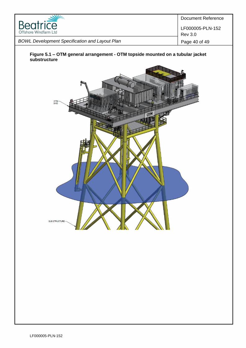
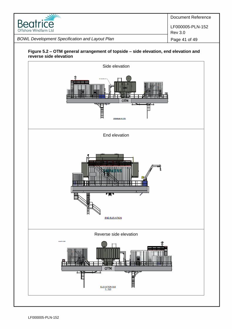
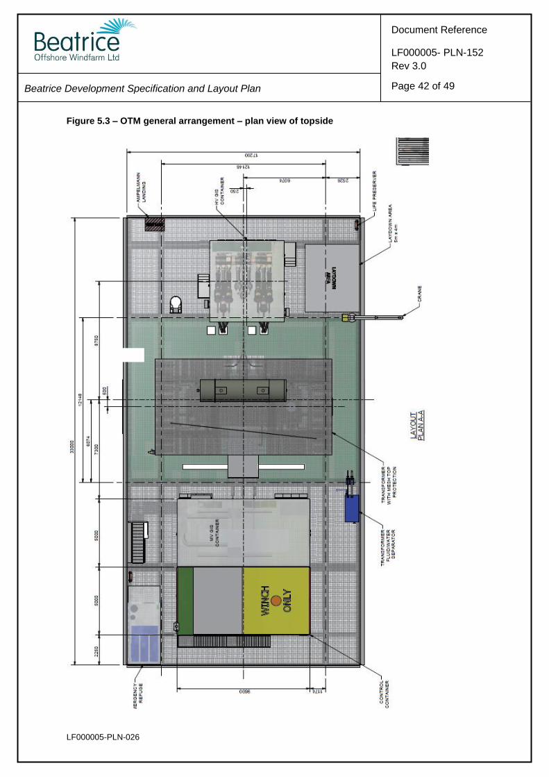
5.4.2 The OTMs are comprised of the OTM topside which sits upon the tubular jacket
substructure. The general arrangement is shown in Figure 5.1 below, and the OTM
topside arrangement is shown in Figures 5.2 and 5.3. Dimensions for the OTMs are
provided in Table 5.2 below.
Table 5.2 – Key dimensions of the OTMs
Parameter Dimension
OTM topside dimensions
(underside of the deck to the top of the transformer tank, as identified in Figure 5.3)
33m (l) x 17.2m (w) x 9m (h)
Height of OTM jacket (above HAT)
19.5m (24.0m above LAT)
(cable deck, as shown in Figure 5.1, at 14.5m above HAT (19.0m above LAT))
Height of topside (above HAT)
28.5m (33.0m above LAT)
LF000005-PLN-152
BOWL Development Specification and Layout Plan
Document Reference
LF000005-PLN-152
Rev 3.0
Page 40 of 49
Figure 5.1 – OTM general arrangement - OTM topside mounted on a tubular jacket substructure
LF000005-PLN-152
BOWL Development Specification and Layout Plan
Document Reference
LF000005-PLN-152
Rev 3.0
Page 41 of 49
Figure 5.2 – OTM general arrangement of topside – side elevation, end elevation and reverse side elevation
Side elevation
End elevation
Reverse side elevation
LF000005-PLN-026
Beatrice Development Specification and Layout Plan
Page 42 of 49
Document Reference
LF000005- PLN-152
Rev 3.0
Figure 5.3 – OTM general arrangement – plan view of topside
LF000005-PLN-152
BOWL Development Specification and Layout Plan
Document Reference
LF000005-PLN-152
Rev 3.0
Page 43 of 49
5.5 Offshore Transformer Module Finishes
5.5.1 OfTW Marine Licence Consent Condition 3.2.2.6 requires that this DSLP include the
following:
The finishes for each OSP;
5.5.2 The topside of each OTM will be finished in light grey, RAL 7035.
5.5.3 The jacket substructure will be finished in golden yellow RAL 1004 from 2m below LAT
up to the interface point at 24m above LAT.
5.6 Length and Proposed Arrangements of Cables
5.6.1 The details of the offshore transmission export cables will be provided, for approval, in
the separate OfTW DSLP.
LF000005-PLN-152
BOWL Development Specification and Layout Plan
Document Reference
LF000005-PLN-152
Rev 3.0
Page 44 of 49
6 Compliance with the Application
6.1 Introduction
6.1.1 In addition to the conditions presented in Table 1.1, Condition 8 of the S36 Consent
states:
The Development [Wind Farm] must be constructed and operated in accordance with the terms of the Application and related documents, including the accompanying ES, the SEIS and Annex 1 of this letter, except in so far as amended by the terms of this section 36 consent.
6.1.2 Sections 6.2 and 6.3 set out information from the ES/SEIS with regard to:
Compliance with the specification and layout assessed; and
Delivery of the stated design-related mitigation.
6.2 Compliance with the Specification and Layout Assessed in the ES/SEIS
6.2.1 The ES and SEIS described a range of specification and layout options that could be
applied during the construction of the Development. This took the form of a broad
‘Rochdale Envelope’ incorporating a variety of options.
6.2.2 Since the Development consents were awarded, the design of the Development has
been substantially refined to that described in this DSLP (and in other relevant Consent
Plans). In order to demonstrate compliance of this refined design, Appendix A provides
a tabulated comparison of project design parameters as presented in the ES/SEIS and
this DSLP.
6.3 Delivery of Design-related Mitigation Proposed in the ES/SEIS
6.3.1 The ES and SEIS detailed a number of mitigation commitments specific to the design
of the Development. Measures are presented in full in Appendix B, which also
identifies where each commitment has been addressed within the DSLP.
LF000005-PLN-152
BOWL Development Specification and Layout Plan
Document Reference
LF000005-PLN-152
Rev 3.0
Page 45 of 49
[Page intentionally left blank]
LF000005-PLN-152
BOWL Development Specification and Layout Plan
Document Reference
LF000005-PLN-152
Rev 3.0
Page 46 of 49
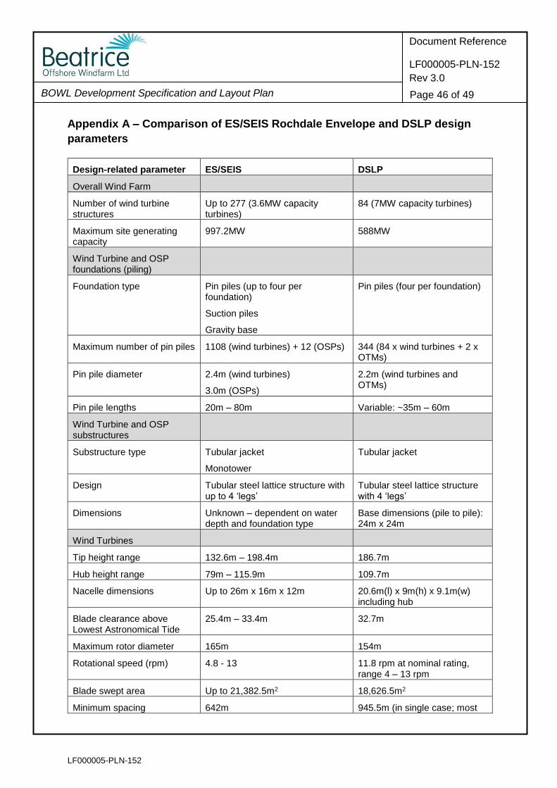
Appendix A – Comparison of ES/SEIS Rochdale Envelope and DSLP design
parameters
Design-related parameter ES/SEIS DSLP
Overall Wind Farm
Number of wind turbine structures
Up to 277 (3.6MW capacity turbines)
84 (7MW capacity turbines)
Maximum site generating capacity
997.2MW 588MW
Wind Turbine and OSP foundations (piling)
Foundation type Pin piles (up to four per foundation)
Suction piles
Gravity base
Pin piles (four per foundation)
Maximum number of pin piles 1108 (wind turbines) + 12 (OSPs) 344 (84 x wind turbines + 2 x OTMs)
Pin pile diameter 2.4m (wind turbines)
3.0m (OSPs)
2.2m (wind turbines and OTMs)
Pin pile lengths 20m – 80m Variable: ~35m – 60m
Wind Turbine and OSP substructures
Substructure type Tubular jacket
Monotower
Tubular jacket
Design Tubular steel lattice structure with up to 4 ‘legs’
Tubular steel lattice structure with 4 ‘legs’
Dimensions Unknown – dependent on water depth and foundation type
Base dimensions (pile to pile): 24m x 24m
Wind Turbines
Tip height range 132.6m – 198.4m 186.7m
Hub height range 79m – 115.9m 109.7m
Nacelle dimensions Up to 26m x 16m x 12m 20.6m(l) x 9m(h) x 9.1m(w) including hub
Blade clearance above Lowest Astronomical Tide
25.4m – 33.4m 32.7m
Maximum rotor diameter 165m 154m
Rotational speed (rpm) 4.8 - 13 11.8 rpm at nominal rating, range 4 – 13 rpm
Blade swept area Up to 21,382.5m2 18,626.5m2
Minimum spacing 642m 945.5m (in single case; most
LF000005-PLN-152
BOWL Development Specification and Layout Plan
Document Reference
LF000005-PLN-152
Rev 3.0
Page 47 of 49
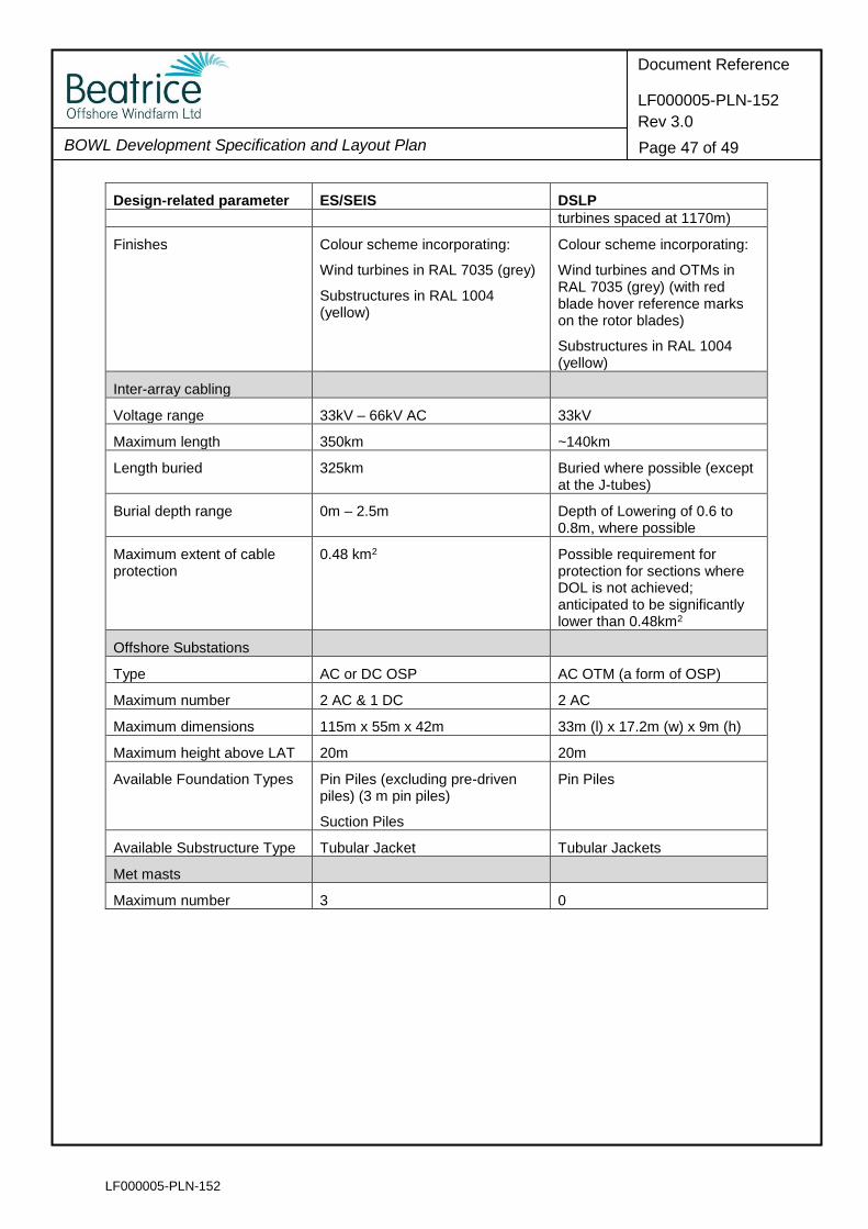
Design-related parameter ES/SEIS DSLP
turbines spaced at 1170m)
Finishes Colour scheme incorporating:
Wind turbines in RAL 7035 (grey)
Substructures in RAL 1004 (yellow)
Colour scheme incorporating:
Wind turbines and OTMs in RAL 7035 (grey) (with red blade hover reference marks on the rotor blades)
Substructures in RAL 1004 (yellow)
Inter-array cabling
Voltage range 33kV – 66kV AC 33kV
Maximum length 350km ~140km
Length buried 325km Buried where possible (except at the J-tubes)
Burial depth range 0m – 2.5m Depth of Lowering of 0.6 to 0.8m, where possible
Maximum extent of cable protection
0.48 km2 Possible requirement for protection for sections where DOL is not achieved; anticipated to be significantly lower than 0.48km2
Offshore Substations
Type AC or DC OSP AC OTM (a form of OSP)
Maximum number 2 AC & 1 DC 2 AC
Maximum dimensions 115m x 55m x 42m 33m (l) x 17.2m (w) x 9m (h)
Maximum height above LAT 20m 20m
Available Foundation Types Pin Piles (excluding pre-driven piles) (3 m pin piles)
Suction Piles
Pin Piles
Available Substructure Type Tubular Jacket Tubular Jackets
Met masts
Maximum number 3 0

LF000005-PLN-152
BOWL Development Specification and Layout Plan
Document Reference
LF000005-PLN-152
Rev 3.0
Page 48 of 49
Appendix B - ES and SEIS Mitigation Commitments
Source Reference (ES or SEIS Chapter)
Details of commitment Implementation
ES Site Selection and Consideration of Alternatives
The minimum distance between turbines will be six rotor diameters.
DSLP Section 4.2
ES Site Selection and Consideration of Alternatives
Turbines will be aligned in straight lines where possible to aid navigational safety, although there may be irregular spacing between the rows.
DSLP Section 4.2
ES Project Description
...the nacelle of the turbine will be fitted with a heli-hoist platform (typically a minimum of 4 m x 4 m) with associated markings and lighting.
DSLP Section 4.6 (see also details in the LMP)
ES Project Description
All parts of the turbine from 18.9 m above LAT upwards will be painted the standard colour for offshore wind turbines, a semi-matt pale grey colour RAL 7035.
DSLP Section 4.6 and 5.5
ES Project Description
The tower and substructure of every turbine will be painted yellow colour RAL 1004 from the level of LAT up to 18.9 m, or up to the height of the navigation lights (whichever is greater) for observational or navigational purposes.
DSLP Section 4.6 and 5.5
ES Shipping and Navigation
The wind turbines will be aligned in straight lines to ensure navigable channels where possible. It is noted there could be slight alterations to wind turbine alignment and spacing due to micro-siting.
DSLP Section 4.2
ES Other Issues Minimum separation distances will be maintained from cables and pipelines as per best practice ensuring there is no risk of damage to these cables during construction and operation of the Project.
DSLP Section 4.2.21
ES Project Description
Turbines will incorporate turbine identification markings including, but not limited to, an identifier on the turbine tower, an identifier on the nacelle roof, contrast stripes on the blades and illuminated signage on the turbine tower.
DSLP Section 4.2 (see also details in the LMP)
ES Project Description
The external colour scheme and marking requirements of the OSP will comply with the guidelines set by the MCA, RYA and IALA.
DSLP Section 4.2, 4.6 and 5.5 (see also details in the LMP)
LF000005-PLN-152
BOWL Development Specification and Layout Plan
Document Reference
LF000005-PLN-152
Rev 3.0
Page 49 of 49
Appendix C – GIS information to Support the DSLP
Provided as a separate accompanying ZIP file containing shapefiles.