bearing capacity of closed and open ended pipe piles installed...
TRANSCRIPT
Indian Journal of Geo-Marine Science Vol.45 (5),May 2016,pp. 703-724
Bearing capacity of closed and open ended pipe piles installed in loose sand with emphasis on soil plug
Mohammed Y. Fattah1 & Wissam H.S. Al-Soudani2
1 CEng., Building and Construction Engineering Department, University of Technology, Baghdad, Iraq,
2 Department of Civil Engineering, College of Engineering, University of Baghdad, Baghdad, Iraq
[Emial: [email protected]]
Received 02 September 2014; revised 01 October 2014
Present study investigates the behaviour of plug on pile load capacity and effect of plug removal. Different parameters are considered such as pile diameter to length ratio, type of installation in loose sand, removal of plug in three stages (50%, 75% and 100%) with respect to length of plug. Kerbala sand from Iraq, which is used as a foundation soil is poorly graded clean sand. It was concluded that the percentage of reduction in pile load capacity for open–ended pile increases with increase of the length of removal of the soil plug. Open-ended pipe pile behaves as a closed-ended if the soil plug formed inside piles is in state of partial plug or full plug. The failure of a pile to plug during driving does not necessarily mean that it will not plug during static loading, since inertia effects, which are present during driving are absent during static loading. This can be observed from the load-settlement curves where the open-ended piles exhibit large resistance to penetration due to mobilization of internal friction during static loading.
[Keywords: Pipe piles, open-ended, closed, bearing capacity, plug].
Introduction
Pile foundations are the part of a structure used to
carry and transfer the load of the superstructure to
the bearing ground located at some depth below
ground surface. Piles are long and slender
members, which transfer the load through weak
compressible strata or water to deeper soil or rock
of less compressibility and high bearing capacity
avoiding shallow soil of low bearing capacity
(Abeb and Smith, 2005).
Pipe piles can be either open-ended or
close-ended. It has been documented that the
behaviour of open-ended piles is different from that
of closed-ended piles (Klos and Tejchman, 1981;
Lee et al., 2003). According to the field test results
of Szechy (1961), the blow count necessary for
driving a pile to a certain depth in sands is lower
for an open-ended pile than for a closed-ended pile.
Thus, it is generally acknowledged that an open-
ended pile requires less installation effort than a
closed-ended pile under the same soil conditions.
However, other research results (Smith et al., 1986;
Brucy et al., 1991) have shown that the mode of
pile driving is an important factor in driving
resistance. If a pile is driven in a fully coring (or
fully unplugged) mode, soil enters the pile at the
same rate as it advances. On the other hand, if a
pile is driven under plugged or partially plugged
conditions, a soil plug finally attaches itself to the
inner surface of the pile, preventing additional soil
INDIAN J. MAR. SCI., VOL. 45, NO 5 MAY 2016
704
from entering the pile. A pile driven in the plugged
mode behaves similarly as a closed-ended pile.
Typically, a large-diameter pipe pile (such as used
in off- shore piling) driven in sand will tend to be
driven in a fully coring mode, while smaller
diameter piles will be plugged, at least partially.
Larger penetration depths and lower relative
densities facilitate soil plug formation. Both the
driving response and static bearing capacity of
open-ended piles are affected by the soil plug that
forms inside the pile during pile driving. In order to
investigate the effect of the soil plug on the static
and dynamic response of an open-ended pile and
the load capacity of pipe piles in general,
experimental pile load tests were performed on
instrumented open- and closed-ended piles driven
into sand. For the open-ended pile, the soil plug
length was continuously measured during pile
driving, allowing calculation of the incremental
filling ratio for the pile. The cumulative hammer
blow count for the open-ended pile was 16% lower
than for the closed-ended pile. The problem is
complicated by the fact that the pile may behave, as
a closed-ended pile during static loading although it
does not plug during installation.
Materials and Methods
This pile is a steel pipe, which is open at both
ends and is driven into the ground with blows to
the top of the pile. After the pile driving, the
ground level is approximately the same both
inside and outside the pile.
This pile is a steel pipe, which is open at
both ends and is driven into the ground with
blows to the top of the pile. On completion
of the pile, driving the ground level is
distinctly lower inside than outside the pile.
The state of plugging of the pile is
determined based on the difference between
the ground levels inside and outside the pile.
Normally, formation of the plug requires
that the pile penetrates into the plugging soil
layer not less than 10 x D length, where D is
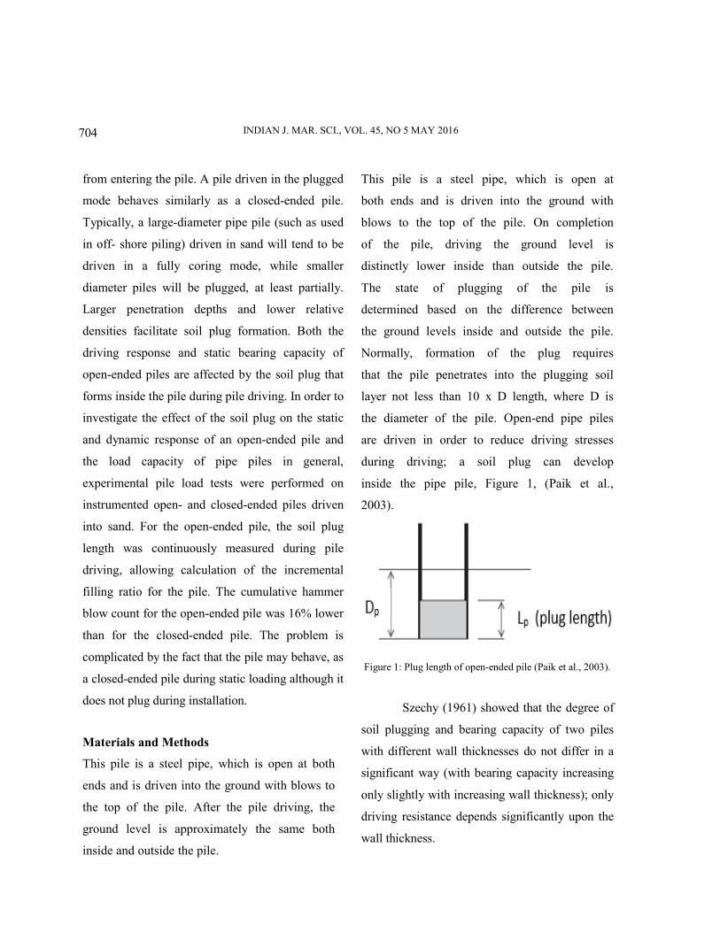
the diameter of the pile. Open-end pipe piles
are driven in order to reduce driving stresses
during driving; a soil plug can develop
inside the pipe pile, Figure 1, (Paik et al.,
2003).
Figure 1: Plug length of open-ended pile (Paik et al., 2003).
Szechy (1961) showed that the degree of
soil plugging and bearing capacity of two piles
with different wall thicknesses do not differ in a
significant way (with bearing capacity increasing
only slightly with increasing wall thickness); only
driving resistance depends significantly upon the
wall thickness.

FATTAH et al.: BEARING CAPACITY OF CLOSED AND OPEN ENDED PIPE PILES
705
Klos and Tejchman (1981) carried out
an experimental work on pile models of tubular
steel of (69.9 and 128 mm) diameter, driven to 1.0
m depth in loose and dense sand where the
relative density is equal to 41% and 70%,
respectively . It has been indicated that, the height
of soil core tends to decrease substantially with
the pile driving depth. It was reported that, "a
tubular pile when driven to a penetration depth
equal to ten times it’s inside diameter will behave
as a solid –base one".
Abdullah and Al-Mhaidib (1999)
studied the bearing capacity of tubular pile into
sandy soil under axial loads. The effect of pile
embedment length and soil plug length on the
bearing capacity of open-ended piles was studies.
The model pile used was steel pipe having 31 mm
outside diameter, 27 mm inside diameter, 2 mm
wall thickness and 380 mm length. The tests were
performed with dense sand corresponding to a
unit weight of approximately 18.9 kN/m3. It was
suggested that the reduction factor must be used
for calculating the bearing capacity of open –
ended piles by static formula, where it was equal
to (0.49) for sandy soil used in the study.
Paik and Salgado (2003) stated that
during the driving of open-ended pipe piles, some
amount of soil will initially enter into the hollow
pipe. Depending on the soil state (dense or loose)
and type (fine-grained or coarse grained),
diameter and length of pile, and the driving
technique, the soil inside the pile may or may not
allow further entry of soil into the pipe. If soil
enters the pipe throughout the driving process,
driving is said to take place in a fully coring mode
and the behaviour is more like that of a non-
displacement pile. However, if the soil forms a
plug at the pile base that does not allow further
entry of soil, then driving is said to be done in a
fully plugged mode. If a pile were driven in the
plugged mode during all of the driving, its load
response would approach that of a displacement
pile. In real field conditions, the behaviour is
generally in between the fully plugged and coring
modes. Further, depending on whether a pipe is
jacked or driven into the ground, the behaviour is
different.
Paik et al., (2003) described the driving
response and static bearing capacities of open-
ended piles affected by the soil plug that forms
inside the pile during pile driving. In order to
investigate the effect of the soil plug on the static
and dynamic response of an open-ended pile and
the load capacity of pipe piles in general, field pile
load tests were performed by Paik et al. (2003) on
instrumented open- and closed-ended piles driven
into sand. For the open-ended pile, the soil plug
length was continuously measured during pile
driving, allowing calculation of the incremental
filling ratio for the pile. The cumulative hammer
blow count for the open-ended pile was 16%
lower than that for the closed-ended pile. The
limit unit shaft resistance and the limit unit base
resistance of the open-ended pile were 51 and

INDIAN J. MAR. SCI., VOL. 45, NO 5 MAY 2016
706
32% lower than the corresponding values for the
closed-ended pile. It was also observed, for the
open-ended pile, that the unit soil plug resistance
was only about 28% of the unit annulus
resistance, and that the average unit of frictional
resistance between the soil plug and the inner
surface of the open-ended pile was36% higher
than its unit outside shaft resistance.
Lehane et al., (2005) incorporated
plugging into design practice in the ICP-05 and
UWA-05 design approaches, for piles in sand,
which are included in the commentary of the
latest American Petroleum Institute (API) design
code. The most significant effect of plugging for
piles in sand is the increase in base resistance,
with a five to seven-fold increase in the ultimate
base resistance mobilized as a pile moved from
the coring to fully plugged condition in sandy soil.
In general, the base resistance amounts to a much
smaller proportion of the total capacity of closed-
ended piles in clay. This may explain the
historical lack of research examining the effects of
plugging on the resistance of piles in clay.
A case study was carried out by
Matsumoto and Kitiyodom (2005) on soil
plugging of two large diameter open-ended steel
pipe piles, which were constructed in Tokyo Bay.
Analysis of the load-displacement relationships of
these piles were carried out using a hybrid
numerical program KWAVE. Good agreement
was found between the analysis results and the
measurement values were found. Then a
parametric study was carried out to investigate
possible methods to increase the bearing capacity
of the pipe piles due to the increase in the soil
plugging effect. It was found that the pile/soil
modelling which was employed in the study can
simulate the behaviour of the pile, the soil and the
soil plug during static loading, if adequate soil
parameters were selected. From the parametric
study, it was found that two methods are effective
to increase the bearing capacity of the pile due to
the increase in the soil plugging effect. One of
them is to increase the length of the fully drained
section in the soil plug. The other is to attach the
cross steel brace inside the pipe pile.
White et al. (2007) concluded that
pressing pile is an alternative method for
installing an open-ended tubular pile, which can
penetrate in an unplugged or a plugged manner.
During unplugged penetration, the pile moves
downwards relative to the internal soil column, in
the manner of a sampler tube.
Penetration is resisted by shaft friction
on the inside (Qsi) and outside (Qso) of the pile and
by base resistance on the annulus of pile wall
(Qw). During plugged penetration, the internal soil
column is dragged downwards, and the pile
exhibits the characteristics of a closed- ended pile
(Paikowsky et al., 1989). Penetration is resisted
by shaft friction on the outside of the shaft (Qso)
and by base resistance on the pile wall (Qw) and
the soil plug (Qp). When a tubular pile is being
installed by the press- in method, (or is being

FATTAH et al.: BEARING CAPACITY OF CLOSED AND OPEN ENDED PIPE PILES
707
loaded to failure- these events are analogous),
penetration will occur by whichever mechanism is
the weakest. If the shaft friction on the inside of
the pile (Qsi) (plus the weight of the soil column)
is greater than the base resistance of the soil
column (Qp), the pile will penetrate in a plugged
manner.
Kikuchi et al., (2010) described the
mechanism of plugging phenomenon at the toe of
vertically loaded open-ended piles. The behaviour
of the surrounding ground at the pile toe on the
observation of the movement of iron particles,
which were mixed with sand to form layers in the
model ground, extracted from visualized X-ray
CT data. The CT images of the experimental
results showed that the condition of wedge
formation below the open-ended pile was clearly
different from that below the closed-ended pile.
Although the penetration resistance of the open-
ended pile and closed-ended pile was similar, the
movement of soil inside the open-ended pile was
not stopped but was restricted, as shown by
intermittent increase and decrease in penetration
resistance during pile penetration.
Although the penetration resistance of
the open-ended pile and closed-ended pile was
similar, the movement of soil inside the open-
ended pile was not stopped but restricted, as
shown by intermittent increase and decrease in
penetration resistance during pile penetration. As
a result, a plugging mechanism.
The present study focuses on the
determination of effect of soil plug on the ultimate
compression capacity of single open – ended steel
pipe pile compared with closed-ended pipe pile
driven or pressed into loose sandy soil. Axial
compression load tests were performed on model
piles embedded in loose sand.
Results and Discussion
Description and details of the material
properties, foundation soil preparation,
loading frame and apparatus, testing
program techniques, and manufacturing of
the setup required to perform the pressed
and driven model piles under static
loading are presented in this section. Twenty
steel pipe piles (open-ended and closed
ended) were used to carry out static
compression loading tests on loose sandy
soil.
Kerbala sand from Iraq, which is used as a
foundation soil in the present study, is poorly
graded clean sand. The sand is sieved on sieve
(No. 4) to remove the coarse particles. Standard
tests were performed to determine the physical
properties of the sand. Details of these properties
are listed in Table 1.
Laboratory tests carried out on soil used included
the following:
1. Specific gravity.
2. Grain size distribution.
3. Maximum and minimum dry unit weight, and
4. Direct shear test.

INDIAN J. MAR. SCI., VOL. 45, NO 5 MAY 2016
708
Sieve analysis was performed in general
accordance with ASTM D422 – 2001, the grain
size distribution of the sand used is shown in
Figure 2. Maximum and minimum index density
tests were performed in general accordance with
ASTM D 4253-2000 and ASTM D 4254-,
respectively.
Direct shear box test was performed in
general accordance with ASTM D 3080-90.
The value of the angle of friction () for the
loose sand was found to be 31o.
Figure 2: Grain size distribution for the sand used.
To simulate the pile load test in the
field, a new apparatus was manufactured. It
consists of the following parts:
1. Steel container.
2. Steel base.
3. Steel loading frame.
4. Axial loading system.
5. Raining frame.
6. Impact hammer device.
7. Mechanical jack.
8. Load cell.
9. Digital weighing indicator.
10. Gear box.
11. AC Drive (speed regulator).
12. UPS (universal power system).
13. Pile driving system –pressing system
installation.
14. Soil plug removal and measurement
devices.
The steel container was 0.75 m in length,
0.75 m in width, and 0.75 m in height. It was
made from five separated parts, one for the base
and the others for the four sides. Each part of the
container was made of 4 mm thick steel plate. At
the internal sides of the container, a steel bar
with 1 cm2
cross sectional area was welded
along three sides and the front side was kept free.
A steel base was manufactured to support the
container and the loading frame weight. The box
was rested on two channels with the ability of
lateral movement.
A steel loading frame was manufactured
to support the mechanical jack, axial loading
system and gear box motor, as shown in Figure 3.
Figure 3: Steel loading frame and axial loading system.

FATTAH et al.: BEARING CAPACITY OF CLOSED AND OPEN ENDED PIPE PILES
709
Table 1: Physical properties of the sand used in the present tests.
Index property Value Specification
Grain size analysis ASTM D 422-2001
D10 ,(mm) 0.35
D30 ,(mm) 0.6
D60 ,(mm) 0.9
Coefficient of uniformity (Cu) 2.57
Coefficient of curvature (Cc) 1.42
Soil classification (USCS) SP
Specific gravity (Gs) 2.66 ASTM D 854-2005
Dry unit weights
Maximum dry unit weight (kN/m3) 18.5 ASTM D 4253-2000
Minimum dry unit weight (kN/m3) 15.2 ASTM D 4254-2000
Maximum void ratio 0.41
Minimum void ratio 0.71
USCS = Unified soil classification system.
The load is applied through a mechanical
jack connected by a gear box motor and AC Drive
(speed regulator), which in turn controls the speed
of the gear box motor (see Figure 3). The
maximum load that can be applied is about 2 tons.
The loading rate wais kept constant at 1 mm/min
as recommended by Bowels (1978) for triaxial
test.
A compression/tension load cell
“SEWHA, Korea” model S-beam type: SS300 is
used to measure the load. A digital weighing
indicator is used for displaying the load amount
“SEWHA, Korea” model SI 4010, with an input
sensitivity of 50 gm. AC drive device (speed
regulator) is connected directly to (gear box) to
control the speed of rotation by inserting the value
of the required speed.
The raining frame consists of two
columns with changeable height. It was
designed to achieve any desired elevation.
This configuration of raining frame helps get
a uniform density by controlling the height of
fall. The rolled beam and the screw that is
connected with the cone ensure that each
particle drops in equal height and uniform
intensity. An impact hammer was used for
soil tamping, it consists of square aluminum
plate (250 mm × 250 mm) and 10 mm in
thickness. The plate is tied to a rod of length
(500 mm) and diameter (30 mm), the
weight of the group is (2.0) kg.

INDIAN J. MAR. SCI., VOL. 45, NO 5 MAY 2016
710
The central displacement of the footing is
read by one dial gage of 0.01 mm sensitivity. The
load increments are continued until the applied
load became constant while the increments of the
settlement measured continued.
Pile driving –pressing system installation.
The pile installation system consists of a base
plate with dimensions of (85 cm × 20 cm) and
20 mm in thickness. This plate involves three
holes (32 mm) in diameter; these holes are
considered as focus place to penetrate the piles
the soil in the box. Two columns are fixed
vertically (28 mm) in diameter to support two
beams designed from aluminum. These parts are
shown in Figure 4.
Figure 4: Pile driving –pressing system installation.
The main part in the driving hammer is the
aluminum rod, it contains steel helmet in the rod
head and steel cylinder which is used as a base
for dropping the hammer weight. The steel
helmet was manufactured with different holes that
are suitable for all model pile sizes that are used
in the tests. These grooves were designed to
ensure the fixity of piles as possible to
reserve the vertical direction for pile penetration
without tilting during the driving process, these
parts are shown in Figure 4. Mechanical jack was
used for pressing pile into the soil at a constant
rate. This jack is fixed to the pile installation
system, these parts are shown in Figure 5.

FATTAH et al.: BEARING CAPACITY OF CLOSED AND OPEN ENDED PIPE PILES
711
Figure 5: Pile pressing system installation.
Soil plug removal and measurement
In this study, the soil plug was removed by a
device manufactured to remove the soil
column entrapped inside the pipe piles
during installation by driving and pressing
device. This tool consists of aluminum tube
400 mm in length and 15 mm in diameter,
inside a steel tube rod 470 mm in length, 8
mm diameter, and spring of 70 mm length,
in the bottom of aluminum tube. A drilling
device, which usually includes a rotating
helical screw blade to act as a screw
conveyor was used to remove the drilled soil
out. The rotation of the blade causes the soil
to move out of the hole being drilled. These
parts are shown in Figure 6. The aluminum
tube has been marked by small grooves
every 10 mm to assist measure the plug
length as shown in Figure 6.
Sand deposit preparation
The sand deposit was prepared using the sand
raining technique. Six trials were performed to
control the density of sand by raining. The sand
was poured from different dropping heights 10,
20, 30, 40, and 50 cm to fulfill the same volume.
The results showed that the weight of sand
required to fill the computed volume increases
with increasing falling height, as a result, the

INDIAN J. MAR. SCI., VOL. 45, NO 5 MAY 2016
712
sand density has a direct proportion with dropping
height at specific boundaries. After completing
the final layer, the top surface was scraped and
leveled by a sharp edge ruler to get as near
as possible a flat surface. The height of drop was
chosen to be 20 cm which maintains to a placing
unit weight of 15.8 kN/m3, void ratio of 0.65
and relative density of 25%.
Figure 6: Soil plug removal and measurement instruments.
Details of Model Piles
Eight open-ended and two closed-ended steel
pipe piles of 20 mm diameter and 1 mm thickness
were used as model piles in the experimental
program of the compression static loading as
shown in Figures 7 and 8 . The length
(embedment length) of the model piles, which
was considered in the experimental programs of
the tests, depends on the ratio of embedment
length to pile diameter, (L/d) ratio. Details of
model piles are shown in Table 2.
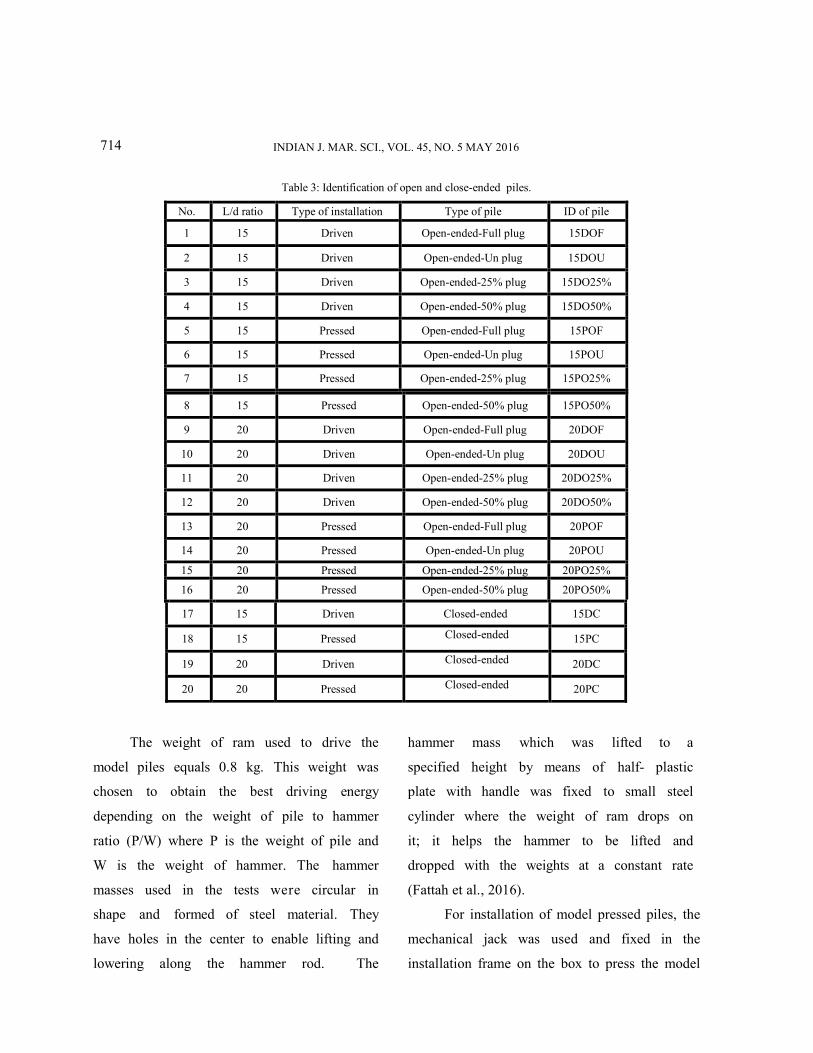
In order to simplify the notation used for
piles, each model is given identification
symbol as indicated in Table 3. ID for each
pile is identification of model pile according
to length of pile to diameter ratio, type of
installation and type of pile.
Table 2: Model piles types and dimensions used in the tests.
Pile No.
Pile type Soil plug situation
Diameter D ( mm )
Length (mm)
L/d=15 L/d=20
1 Closed-ended -
20 300 400
2-a Open-ended Fll Plug
2-b Open-ended 50 % Plug
2-c Open-ended 25 % Plug
2-d Open-ended 0 % Unplugged

FATTAH et al.: BEARING CAPACITY OF CLOSED AND OPEN ENDED PIPE PILES
713
Figure 7: Pile models used in testing program.
Figure 8: Development of plugs in pile models (open type) used in testing program.
Installation of model driven and pressed piles
The driving hammer was fixed to the box to
penetrate the model piles to the required
length. The weight that is used to drive
the model piles was calculated
approximately. The weight is taking into
consideration many factors that affect pile
capacity.
The model piles are vertically
installed in specific hole that is being in the
hammer plate and the rod of hammer was
lowered to the model piles until the pile
helmet will be in contact with the model
pile. After the model pile head enters inside
the helmet, the driving process begins with
dropping a certain weight from a specified
height, and the results of the number of
blows are recorded each 25 mm of model
pile length until reaching the final required
length of penetration.
INDIAN J. MAR. SCI., VOL. 45, NO. 5 MAY 2016
714
Table 3: Identification of open and close-ended piles.
No. L/d ratio Type of installation Type of pile ID of pile
1 15 Driven Open-ended-Full plug 15DOF
2 15 Driven Open-ended-Un plug 15DOU
3 15 Driven Open-ended-25% plug 15DO25%
4 15 Driven Open-ended-50% plug 15DO50%
5 15 Pressed Open-ended-Full plug 15POF
6 15 Pressed Open-ended-Un plug 15POU
7 15 Pressed Open-ended-25% plug 15PO25%
8 15 Pressed Open-ended-50% plug 15PO50%
9 20 Driven Open-ended-Full plug 20DOF
10 20 Driven Open-ended-Un plug 20DOU
11 20 Driven Open-ended-25% plug 20DO25%
12 20 Driven Open-ended-50% plug 20DO50%
13 20 Pressed Open-ended-Full plug 20POF
14 20 Pressed Open-ended-Un plug 20POU
15 20 Pressed Open-ended-25% plug 20PO25%
16 20 Pressed Open-ended-50% plug 20PO50%
17 15 Driven Closed-ended 15DC
18 15 Pressed Closed-ended 15PC
19 20 Driven Closed-ended 20DC
20 20 Pressed Closed-ended 20PC
The weight of ram used to drive the
model piles equals 0.8 kg. This weight was
chosen to obtain the best driving energy
depending on the weight of pile to hammer
ratio (P/W) where P is the weight of pile and
W is the weight of hammer. The hammer
masses used in the tests were circular in
shape and formed of steel material. They
have holes in the center to enable lifting and
lowering along the hammer rod. The
hammer mass which was lifted to a
specified height by means of half- plastic
plate with handle was fixed to small steel
cylinder where the weight of ram drops on
it; it helps the hammer to be lifted and
dropped with the weights at a constant rate
(Fattah et al., 2016).
For installation of model pressed piles, the
mechanical jack was used and fixed in the
installation frame on the box to press the model

FATTAH et al.: BEARING CAPACITY OF CLOSED AND OPEN ENDED PIPE PILES
715
pile to penetrate the required length as shown in
Figure 5.
Some of during test photos are shown in
Figures 9 to 11.
Figure 9: Removing of soil plug
Figure 10: Piles installed in the model.
Figure 11: Testing of a pile.
Predicting of Pile Load Capacity (Ultimate Pile Capacity in Compression).
In this section, the pile capacity equation of
the American Petroleum Institute, API (1993) is
used to calculate the predicted pile load capacity
(Ppre).
According to API method (API, 1993), the total
load capacity of piles Qt can be determined by the
equation:
For driven piles :
………..(1)
For drilled and grouted piles :
……………..(2)
where:
a) = external shaft
friction capacity, equal to the sum of the
external shaft friction forces over the pile
penetration depth, after detection of the
depth zo along which skin friction is
ignored.
L = pile length,
W = weight of pile,
Zo = length of pile above soil,
fo = external unit shaft friction, and
= external lateral contact area with
the soil for layer in which is
applied.
b) = end –bearing capacity of a
pile assumed to be plugged.
= unit end bearing capacity,

FATTAH et al.: BEARING CAPACITY OF CLOSED AND OPEN ENDED PIPE PILES
716
= total cross-
sectional area at the tip,
= annular cross-sectional area of the
tip, and
= cross-sectional area of the internal
soil column at the tip.
c) = end–
bearing capacity of an open- ended pile
without a plug , corresponding to the sum
of the end-bearing capacity of the annulus
and the shaft frictional capacity of the
internal soil column
= internal unit skin friction,
= internal surface area of soil-to-pile
contact for the layer where is
applied,
= length of pile along in which the
internal soil column may have
been removed.
d) =
weight of pile,
= annular cross-sectional area of the
pile,
= specific weight of steel (77 kN/m3),
= total unit weight of soil, and
= Length of pile sections along which
the tubular cross –sectional area
and are constant.
e) For open- ended driven piles, the end-
bearing capacity is limited by the bearing
capacity of the internal soil column, in
other words, it is taken as the lower of the
two values :
If , the pile is said to be
"plugged".
If , the pile is said to be
"unplugged".
An open-ended pile behaves under static
condition as an "unplugged" pile as long as
the internal skin friction
remains lower than the end-bearing
capacity of the internal soil column
(
Unplugged open-ended pile:
Plugged open-ended pile:
For pipe piles in cohesionless soil, the skin
friction may be calculated using the equation
(API, 1993):
f = K v’ tan …(3)
where:
K = coefficient of lateral earth pressure (ratio of horizontal to vertical normal effective stress),
= effective vertical overburden pressure at
the point in question, and = friction angle between the soil and pile
wall.
INDIAN J. MAR. SCI., VOL. 45, NO 5 MAY 2016

FATTAH et al.: BEARING CAPACITY OF CLOSED AND OPEN ENDED PIPE PILES
715
The unit end-bearing (tip resistance) of
pile in cohesionless soil may be computed using
the equation (API, 1993):
qp = v’ Nq ……………..(4)
where:
= effective overburden pressure,
and
= dimensionless bearing capacity
factor.
The API method illustrated in the previous
section is used here to calculate the pile bearing
capacity for different plug conditions. Table 4
shows the predicted bearing capacity values
obtained from the theoretical API method in
addition to values measured during the tests. The
failure load in experimental result is considered as
the load at which the settlement continues under
constant load. It can be noticed that the API
method underestimates the pile bearing capacity
for all pile and soil conditions.
Table 4: Measured pile load capacity (Pm) and predicted pile bearing capacity values obtained from the theoretical API method ,
pile length = 40 cm.
Type of Installation Type of Pile Measured Pile Load
Capacity (N) Predicted Pile Load Capacity ,
API method (N)
Driven
20DC 148 81.6
20DOF 140 58.3
20DO50% 137 54.5
20DO25% 80 52.6
20DOU 77 50.75
Pressed
20PC 156 81.6
20POF 155 52.6
20PO50% 142 51.7
20PO25% 104 51.2
20POU 64 50.75
717

INDIAN J. MAR. SCI., VOL. 45, NO. 5 MAY 2016
718
Interpretation of Pile Load Capacity
Several methods (criteria) are used to define the
failure load from load-settlement curves; some of
these methods are Davison, Chin Konder, Fuller
and Hoy, De Beer, Terzaghi Criteria and constant
load vs. increase of settlement according to Civil
Engineering Code of Practice No.4, 1954).
Throughout the pile load test, the pile is loaded to
failure, the settlement continues at fixed load
(failure), and this load is considered as the failure
pile load capacity (Pf).
According to the Civil Engineering Code of
Practice No.4, (1954), the ultimate load capacity is
that load at which the rate of settlement continues
at a constant rate. Table 5 shows the interpretation
of pile load capacity for 40 cm long of closed and
open-ended piles driven into loose sand.
Presentation of Load Settlement Curves.
Open – ended pipe pile was chosen as a reference
pile to compare all other types of model pile
ultimate capacity, settlement and failure pile load
capacity. This pile was chosen for each model
installed in loose sand, type of installation and
length of pile.
Open- ended piles.
Sixteen open-ended piles have been tested and
these piles are divided into four groups:
I. Open –ended piles with full plug: in this type
of piles, the soil column inside the pipe is not
removed before pile test.
II. Open –ended with 50% plug: in this type of
piles, 50% of the total length of the soil
column inside the pipe is removed before
pile test.
III. Open –ended with 25% plug: in this type of
piles, 75% of the total length of the soil
column inside the pipe is removed before
pile test.
IV. Unplugged open –ended piles: in this type
of piles, 100% of the total length of the soil
column inside the pipe is removed before
pile test.
Table 5: Interpretation of driven pile load capacity in loose sand (N).
Measured Failure Load
Civil Engineering Code of Practice No.4, (1954)
No.
148 146 20DC 1
142 140 20DOF 2
140 137 20DO50% 3
83 80 20DO25% 4
80 77 20DOU 5
FATTAH et al.: BEARING CAPACITY OF CLOSED AND OPEN ENDED PIPE PILES
716
Figures 12 to 15 present the load- settlement
curves for model open-ended piles (full plug, 50%
plug, 25 % plug, and unplugged) and show the
effect of removing of the soil column inside the
pile. It can be noticed that all load-settlement
curves exhibit punching shear failure.
Closed ended piles
Four models of closed ended pile were tested in
compression static load. The piles were installed by
two types of installation system (driving and
pressing) in loose sand. The observed load-
settlement relations are described in Figures 16 and
17.
Table 6 presents the pile load capacity
according to Civil Engineering Code of Practice
No.4, 1954 for driven and pressed piles of 40 cm
and 30 cm length closed and open-ended driven or
pressed into sand of different densities.
According to Szechy (1961), the settlement
of an open-ended pile is greater than that of a
closed-ended pile under the same load and soil
conditions. This means that, if ultimate load
capacity is defined with reference to a standard
settlement of 10% of the pile diameter, for
example, the load capacity of open- ended piles is
typically lower than that of closed-ended piles.
However, the difference in load capacities varies
within a wide range, depending on the degree of
soil plugging during driving. This is compatible
with the findings of Szechy (1961).
According to Paik and Lee (1994), the
difference between the load capacity of closed- and
open-ended piles decreases with increasing driving
depth, as the soil plugging effect increases.
Pile driving results in densification of all
sands immediately below the pile tip, regardless of
their initial relative density (Szechy, 1961). This
densification extends within the first few diameters
of the soil core. Densification is an important
ingredient in the formation of an arch and
promoting plugging (Iskander 2010, Fattah and Al-
Soudani, 2016).
719

INDIAN J. MAR. SCI., VOL. 45, NO. 5 MAY 2016
720
Table 6: Pile bearing capacity according to the Civil Engineering Code of Practice No.4, (1954).
On the other hand, the length of pile plays an
important role in controlling the pile load capacity
in pressed piles. When L/d = 20, there is greater
increase in pile capacity due to mobilization of skin
friction, while when L/d = 15 , the improvement in
load carrying capacity is due to dilation effect in
the latter type.
During the driving of open-ended pipe piles,
some amount of soil will initially enter into the
hollow pipe. Depending on the soil state (dense or
loose) and type (fine-grained or coarsegrained),
diameter and length of pile, and the driving
technique, the soil inside the pile may or may not
allow further entry of soil into the pipe. When the
open-ended pile is fully plugged, its load carrying
capacity is close to closed ended pile as shown in
Table 6.
Type of installation Type of pile Measured pile load
capacity (N)
Driven
20DC 148
20DOF 140
20DO50% 137
20DO25% 80
20DOU 77
Pressed
20PC 156
20POF 155
20PO50% 143
20PO25% 104
20POU 64
Driven
15DC 132
15DOF 150
15DO50% 128
15DO25% 112
15DOU 55
Pressed
15PC 103
15POF 112
15PO50% 91
15PO25% 61
15POU 59

FATTAH et al.: BEARING CAPACITY OF CLOSED AND OPEN ENDED PIPE PILES
723
Figure 12: Load- settlement relations for open-ended driven piles in loose sand, L=40 cm.
Figure 13: Load- settlement relations for open-ended pressed piles in loose sand, L=40 cm.
Figure (14): Load- settlement relations for open-ended driven piles in loose sand, L=30 cm.
Figure (15): Load- settlement relations for open-ended pressed piles in loose sand, L=30 cm.
Figure (16): Load- settlement relations for closed – ended driven and pressed piles in loose sand, L=40 cm.
Figure (17): Load- settlement relations for closed – ended
driven and pressed piles in loose sand, L=30 cm.
721
INDIAN J. MAR. SCI., VOL. 45, NO. 5 MAY 2016
724
Klos and Tejchman (1977) concluded that a
tubular pile when driven to a penetration depth
equal to ten times its inside diameter will behave as
a solid –based one. In this study, it was concluded
that when L/d 15, the load carrying capacity of
fully plugged open-ended pipe pile may be equal or
grater than that of closed-ended pile.
Piles, which plug during static loading may,
nevertheless, have smaller tip bearing capacities
than their closed-end counterparts. On the other
hand, the inside skin friction may contribute
considerably to the load carrying capacity.
The failure of a pile to plug during driving
does not necessarily mean that it will not plug
during static loading, since inertia effects, which
are present during driving are absent during static
loading. This can be observed from the load-
settlement curves where the open-ended piles
exhibit large resistance to penetration due to
mobilization of internal friction during static
loading.
The driven pile mobilizes all of its internal
and external friction intermittently during
penetration and, as a result, the soil core advances
up the pile. As penetration progresses, the soil core
inside the pile may develop sufficient frictional
resistance along the inner pile wall to prevent
further soil intrusion, causing the pile to become
plugged. Larger penetration depths and lower
relative densities facilitate soil plug formation.
Previous studies showed that a short open-ended
pile has lower load capacity than an equivalent
closed-ended pile. The present study proved that if
the pile is embedded in loose sand, the fully
plugged open-ended pile reveals a load carrying
capacity equal or may be greater than closed-ended
pile.
Conclusions
Open-ended pipe piles behave as a closed-ended if
the soil plug formed inside piles in state partial plug
or full plug. Length of soil plug depends on the type
of installation. The driven pile mobilizes all of its
internal and external friction intermittently during
penetration and, as a result, the soil core advances
up the pile. Whether open-ended piles are driven or
pressed in the fully coring -fully unplugged mode
or in the partially plugged mode, the plug does
contribute to static pile base capacity. The
settlement of an open-ended pile is greater than that
of a closed-ended pile under the same load and soil
conditions. This means that, if ultimate load
capacity is defined with reference to a standard
settlement of 10% of the pile diameter, for example,
the load capacity of open- ended piles is typically
lower than that of closed-ended piles. However, the
difference in load capacities varies within a wide
range, depending on the degree of soil plugging
during driving. When a pipe pile is driven to a
penetration depth equal to fifteen times its inside
diameter, it will behave as a solid–based and the
load carrying capacity of fully plugged open-ended
pipe pile may be equal or grater than that of closed-
ended pile. The failure of a pile to plug during
driving does not necessarily mean that it will not
722

FATTAH et al.: BEARING CAPACITY OF CLOSED AND OPEN ENDED PIPE PILES
723
plug during static loading, since inertia effects,
which are present during driving are absent during
static loading. This can be observed from the load-
settlement curves where the open-ended piles
exhibit large resistance to penetration due to
mobilization of internal friction during static
loading.
References:
1. Abeb, A. and Smith, I.G. (2005), “Pile Foundation Design
– A Student Guide”, School of Built Environment,
Napier University, Edinburgh.
2. Abdullah I. and Al-Mhaidib, A. (1999), “Bearing Capacity
of a Model Pile in Sand under Different Loading Rates”,
The International Society of Offshore and Polar
Engineers. Vol. 1, pp. 724-730.
3. American Petroleum Institute (API), (1993),
“Recommended Practice for Planning, Designing and
Constructing of Fixed Offshore Platforms – Load and
Resistance Factor Design, RP2A-LRFD,20th Edition,
D.C:66-68.
4. ASTM D4253-2000, “Standard Test Method for Maximum
Index Density and Unit Weight of Soils Using a
Vibratory Table”, American Society for Testing and
Materials.
5. ASTM D4254-2000, “Standard Test Method for
Minimum Index Density and Unit Weight of Soils
and Calculation of Relative Density”, American
Society for Testing and Materials.
6. ASTM D422-2001, “Standard Test Method for Particle
Size-Analysis of Soils”, American Society for Testing
and Materials.
7. ASTM D854-2005, “Standard Test Method for Specific
Gravity of Soil Solids by Water Pycnometer”, American
Society for Testing and Materials.
8. ASTM D3080-1998, “Standard Test Method for Direct
Shear Test of Soils under Consolidated Drained
Conditions”, American Society for Testing and
Materials.
9. Bowels, J.E. (1978): “Engineering Properties of Soils and
Their Measurement”, Second Edition, McGraw-Hill
International Book Company.
10. Brucy, F., Meunier, J., Nauroy, J.F. (1991), “Behavior of
Pile Plug in Sandy Soils During and After Driving”,
Proceeding of the 23rd Annual Offshore Technology
Conference, Houston, 6514, pp. 145-154.
11. Fattah, M. Y., Al-Soudani, W. H. S., (2016), "Bearing
Capacity of Open-Ended Pipe Piles with Restricted Soil
Plug", Ships and Offshore Structures, Vol. 11, 5, pp.
501-516, Taylor & Francis, DOI:
10.1080/17445302.2015.1030247, London W1T 3JH,
UK.
12. Fattah, M. Y., Al-Soudani, W. H. S., Omar, M., (2016),
"Estimation of Bearing Capacity of Open-ended Model
Piles in Sand", Arabian Journal of Geosciences, 9:242,
DOI 10.1007/s12517-015-2194-8.
13. Kikuchi, Y., Mizutani, T., and Morikawa, Y.
(2010),”Plugging Mechanism of Open-Ended Piles”,
Soil-Foundation-Structure Interaction-Orense, Chouw
and Pender (eds), pp. 27-32.
14. Klos, J. and Tejchman, A. (1977), “Analysis of Behavior
of Tubular Piles in Subsoil”, Proceedings of the 9th
international conference on Soil Mechanics and
Foundation Engineering, Tokyo.Vol.1, pp. 605-608.
15. Klos, J., and Tejchman, A. (1981), “Bearing Capacity
Calculation for Pipe Piles”, Proceedings of the 10th
international conference on Soil Mechanics and
Foundation Engineering, Stockholm, 2, pp.751-754.
16. Kraft, L.M. (1991),” Performance of Axially Loaded Pipe
Piles in Sand”, Journal of Geotechnical Engineering,
ASCE, Vol.117, No.2, pp. 272-296.
17. Lee, J., Salgado, R., Paik, K. (2003), ” Estimation of Load
Capacity of Pipe Piles in Sand Based on Cone
Penetration Test Result”, Journal of Geotechnical and
Geoenvironmental Engineering, ASCE, 129(5), pp. 391
– 403.

INDIAN J. MAR. SCI., VOL. 45, NO. 5 MAY 2016
724
18. Lehane, B.M., Scheider, J.A. and Xu, X., (2005), ” CPT
Based Design of Driven Piles in Sand for Offshore
Structures”, University of Western Australia, Perth.
19. Matsumoto, T. and Kitiyodom, P. (2005), ”Case Study on
Soil Plugging of Open-Ended Steel Pipe Piles in Tokyo
Bay”, Taylor and Francis Group Plc, London, UK.
20. O’Neill, M.W. and Raines, R.D. (1991), ”Load Transfer
for Pipe Piles in Highly Pressured Dense Sand”, Journal
of Geotechnical Engineering, ASCE, Vol.117, No. 8, pp.
1208 – 1226.
21. Paikowski, S.G., Whitman, R.V. and Baligh, M.M.
(1989), ” A New Look at the Phenomenon of Offshore
Pile Plugging”, Marine Geotechnical, (8), pp. 213-230.
22. Paik, K. and Salgado, R. (2003),” Determination of
Bearing Capacity of Open-Ended Piles in Sand”, Journal
of Geotechnical and Geoenvironmental Engineering,
ASCE, 129 (1), pp. 46 – 57.
23. Paik, K., Salgado, R., and Lee. J. Kim B (2003),
”Behavior of Open-and Closed-Ended Piles Driven into
Sands. Journal of Geotechnical and Geoenvironmental
Engineering, ASCE, Vol. 129, No. 4, pp. 296 – 306.
24. Raines, R.D., Ugaz, O.F. and O’Neill, M.W.
(1992),”Driving Characteristics of Open-Toe Piles in
Sand”, Journal of Geotechnical Engineering, ASCE, Vol.
118, No. 1, pp. 72 – 88.
25. Randolph, M. F., May, M., Leong, E.C., and Houlsby, G.
T. (1991), “One-Dimensional Analysis of Soil Plug in
Pipe Piles”, Geotechnique, Vol. 41, No. 4, pp. 587 – 598.
26. Smith, I. M., To P. and Willson, S. M. (1986),” Plugging
of Pipe Piles”, Proceedings of the 3rd International
Conference on Numerical Methods in Offshore Pilling,
pp. 53-73.
27. Szechy, C. (1961),” The Effect of Vibration and Driving
Upon the Voids in Granular Soil Surrounding a Pile”,
Proceedings of the 5th international conference on Soil
Mechanics and Foundation Engineering, 2, pp.161-164.
28. White, D.J., Sidhu, H.K., Finlay, T.C.R., Bolton, M.D.
and Nagayama, T. (2007),” Press-In Piling: The
Influence of Plugging on Drivability”, 8th International
Conference of the Deep Foundation Institute, New York,
pp.299-310.