basic sanitary wastewater treatment
TRANSCRIPT

Basic Sanitary Wastewater Treatment
Nick Cooper – AECOM USA
Robert Garner AECOM UAERobert Garner – AECOM UAE
4 February 2013Basic Sanitary Wastewater TreatmentWater Arabia 2013
Nick Cooper [email protected]
Vice President, Wastewater Technical Practice Leader
Project Manager – Wastewater Treatment, Biosolids, Water ReuseWater Reuse
35 years - Treatment Plant Planning and Design
Experience – USA, Canada, Middle East, UK, Southeast Asia, South America
Middle East Experience: 1998 - Presentdd e ast pe e ce 998 ese t
Contributing Author:
Metcalf & Eddy - Water ReuseMetcalf & Eddy Water Reuse
MOP 32 – Energy Conservation
Basic Sanitary Wastewater TreatmentWater Arabia 2013

Robert B. Garner [email protected]
Principal Engineer – Abu Dhabi / Gulf Region
Project Manager – Water & Wastewater Treatment, j gWater Reuse
27 years – Process Applications Design, Treatment Plant Design and ConstructionPlant Design and Construction
Experience – UK, Middle East.
Middle East Experience: 1995 PresentMiddle East Experience: 1995 – Present
Specializations:-
Pumping Systems Preliminary Treatment ScreeningPumping Systems,Preliminary Treatment, Screening and Sludge Treatment.
Basic Sanitary Wastewater TreatmentWater Arabia 2013
3

Agenda8:30 AM – 10:00 AM
I t d ti t W t t T t t T f T t t- Introduction to Wastewater Treatment, Types of Treatment- Pumping and Preliminary Treatment
10.00 AM – 10:30 AM Break
10:30 AM – 12:0010:30 AM 12:00- Primary Treatment- Biological Treatment - Overview- Biological Treatment - Suspended Growth (Activated Sludge)- Biological Treatment – Fixed Growthg- Clarification - Filtration- Disinfection
12:00 to 1:00 PM Lunch Break12:00 to 1:00 PM Lunch Break
1:00 PM – 2:00 PM- Odor Control- Process Modeling
Discussion- Discussion
2:00 – 2:30 Break
2:30 PM – 4:00 PM- Sludge Treatment Overview
Basic Sanitary Wastewater TreatmentWater Arabia 2013
4
- Thickening- Digestion- Dewatering/Drying

Session Objectives
• Overview of Basic Sanitary Wastewater Treatment
• Design considerations• Design considerations
• Types of Treatment – Liquid Stream
• Treatment Systems – Residual Solids StreamTreatment Systems Residual Solids Stream
• Process descriptions and design parameters
Basic Sanitary Wastewater TreatmentWater Arabia 2013
5
References
Basic Sanitary Wastewater TreatmentWater Arabia 2013
6

Overview of Basic Sanitary Wastewater Treatment
Basic Sanitary Wastewater TreatmentWater Arabia 2013

DC WATER BLUE PLAINS DC WATER BLUE PLAINS WWTP, USAWWTP, USA1400 MLD Capacit1400 MLD Capacit1400 MLD Capacity1400 MLD Capacity
8Basic Sanitary Wastewater EngineeringWater Arabia 2013

F WAYNE HILL WRC, GEORGIA USAF WAYNE HILL WRC, GEORGIA USA227 MLD Capacit227 MLD Capacit227 MLD Capacity227 MLD Capacity
Basic Sanitary Wastewater TreatmentWater Arabia 2013

MALABAR STP, SYDNEY AUSMALABAR STP, SYDNEY AUS1000 MLD Capacit1000 MLD Capacit1000 MLD Capacity1000 MLD Capacity
Basic Sanitary Wastewater EngineeringWater Arabia 2013

Compact Treatment 20 MLD Membrane Bioreactor STP
60 MLD Membrane Bioreactor STP
10 MLD Membrane Bioreactor STP10 MLD Membrane Bioreactor STP
11Basic Sanitary Wastewater TreatmentWater Arabia 2013

Palm Jumeirah
21 MLD Palm Jumeirah
WRF

Where is the Treatment Plant?
13Basic Sanitary Wastewater EngineeringWater Arabia 2013
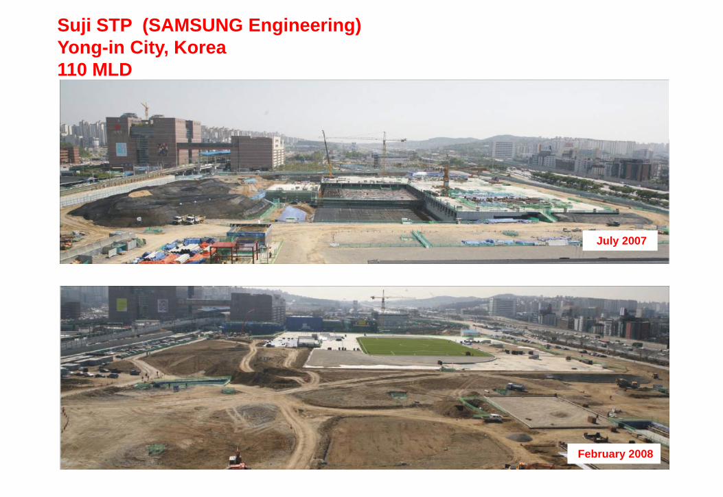
Suji STP (SAMSUNG Engineering)Yong-in City, Korea110 MLD110 MLD
July 2007
February 2008

Terminologygy
Basic Sanitary Wastewater TreatmentWater Arabia 2013

Terminology
BOD – Biochemical Oxygen Demand
COD – Chemical Oxygen Demandyg
TSS – Total Suspended Solids
Coliform - Bacteria Colony Forming Units
DO – Dissolved Oxygen
Screenings – Floating debris removed by screening units
Grit – Inert debris (sand, coffee grounds, egg shells)
FOG – Fats, Oils, Grease
Sludge/Biosolids – Residual Waste from Biological Treatment
TSE – Treated Sewage Effluent
Mi d Li Bi i A ti t d Sl d R t
16
Mixed Liquor – Biomass in Activated Sludge Reactors
Basic Sanitary Wastewater TreatmentWater Arabia 2013

Terminology, Cont’d
Preliminary Treatment
Primary TreatmentPrimary Treatment
Secondary Treatment
Biological TreatmentBiological Treatment
Activated Sludge /Suspended Growth Processes
Fixed Film/ Attached Growth ProcessesFixed Film/ Attached Growth Processes
Tertiary Treatment
Nutrient RemovalNutrient Removal
Return Activated Sludge
Waste Activated Sludge
17
Waste Activated Sludge
Basic Sanitary Wastewater TreatmentWater Arabia 2013

Overview of Basic Sanitary Wastewater Treatment
• Wastewater is 99.97% Pure Water
• Wastewater Treatment is a series of physical, chemical and biological processes to improve quality before reuse or disposaldisposal
• Wastewater Treatment can be to any level, even drinking water quality, with the right selection of processesquality, with the right selection of processes
• Astronauts recycle wastewater for potable use every day
• Treatment depends on end use of the water and environmental impact
Basic Sanitary Wastewater TreatmentWater Arabia 2013
18

Sewageg
Why treat it? Reduce pollution in rivers
R d ll ti i• Reduce pollution in sea• Improve aesthetics Bacteria and viruses are harmful to Bacteria and viruses are harmful to
people Fish need oxygen to live Reuse – valuable resource

Pollutants/Contaminants in Wastewater
• Floating Debris- Unsightly in discharge and residual solidsUnsightly in discharge and residual solids- Can damage equipment in plant- Plastics, sticks, paper
• Grit• Grit- Generally inert, not treatable- Damaging to equipment in plant
Sand egg shells plastic particles coffee grounds- Sand, egg shells, plastic particles, coffee grounds• Oil and grease
- Can affect settling of sewage- Creates foam, scum- Unsightly in discharge- Organic and inorganic sources
Basic Sanitary Wastewater TreatmentWater Arabia 2013
20
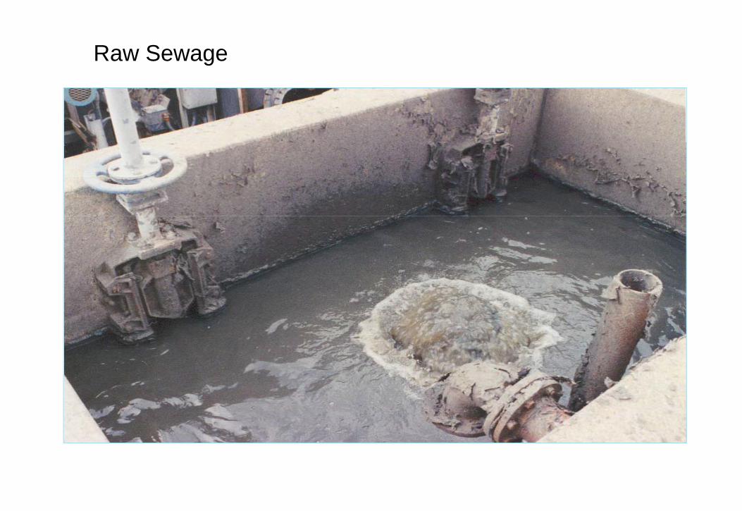
Raw Sewage

Screenings
• Unsightly in discharge and residual solids• Can damage equipment in plant• Floating debris - plastics, sticks, paper

Grit
• Generally inert, not treatable• Damaging to equipment in plant
S d h ll l ti ti l ff d• Sand, egg shells, plastic particles, coffee grounds

Fats, Oil & Grease
• Can affect settling of sewage• Creates foam, scum
U i htl i di h• Unsightly in discharge• Organic and inorganic sources

Pollutants/Contaminants in Wastewater
• BOD – Biochemical Oxygen Demand- Removes oxygen from river waterRemoves oxygen from river water- Harmful to fish if depletes oxygen in aquatic environment- Organic compounds
• TSS Total Suspended Solids• TSS – Total Suspended Solids- Affects water clarity- Can carry BOD
Includes floating and colloidal material- Includes floating and colloidal material- Organic and inorganic compounds
Basic Sanitary Wastewater TreatmentWater Arabia 2013
25

Suspended Solids as SludgeSuspended Solids as Sludge
• Affects water clarityAffects water clarity• Can carry BOD• Includes floating and colloidal material• Organic and inorganic compoundsg g p

Pollutants/Contaminants in Wastewater
• Nitrogen- Ammonia toxic in aquatic environmentsAmmonia toxic in aquatic environments- Promotes algae growth in water bodies- Ammonia, organic nitrogen, nitrates, nitrites
• Phosphorus• Phosphorus- Promotes algae growth in aquatic environments
• Bacteria and viruses- Adverse health effects
• Toxic Materials- Can affect treatment- Toxic to humans and aquatic environments- Phenols, organic compounds, medical wastes, metals
Basic Sanitary Wastewater TreatmentWater Arabia 2013
27

Bacteria Toxic materials• Can affect treatment• Toxic to humans and
aquatic environments
• Health effects
aquatic environments• Phenols, organic
compounds, medical wastes, metals

Simplified Principle
BOD = 2.5 mg/L
Sewage Treatment
BOD = 250 mg/L BOD < 25 mg/L
Works
River /
Sludge Disposal
River / Sea

Surface Water Discharge

Treated Sewage Effluent (TSE)
• Irrigation• Fire protection
I d t i l W t• Industrial Water• District Cooling• Groundwater Recharge
31Basic Sanitary Wastewater EngineeringWater Arabia 2013
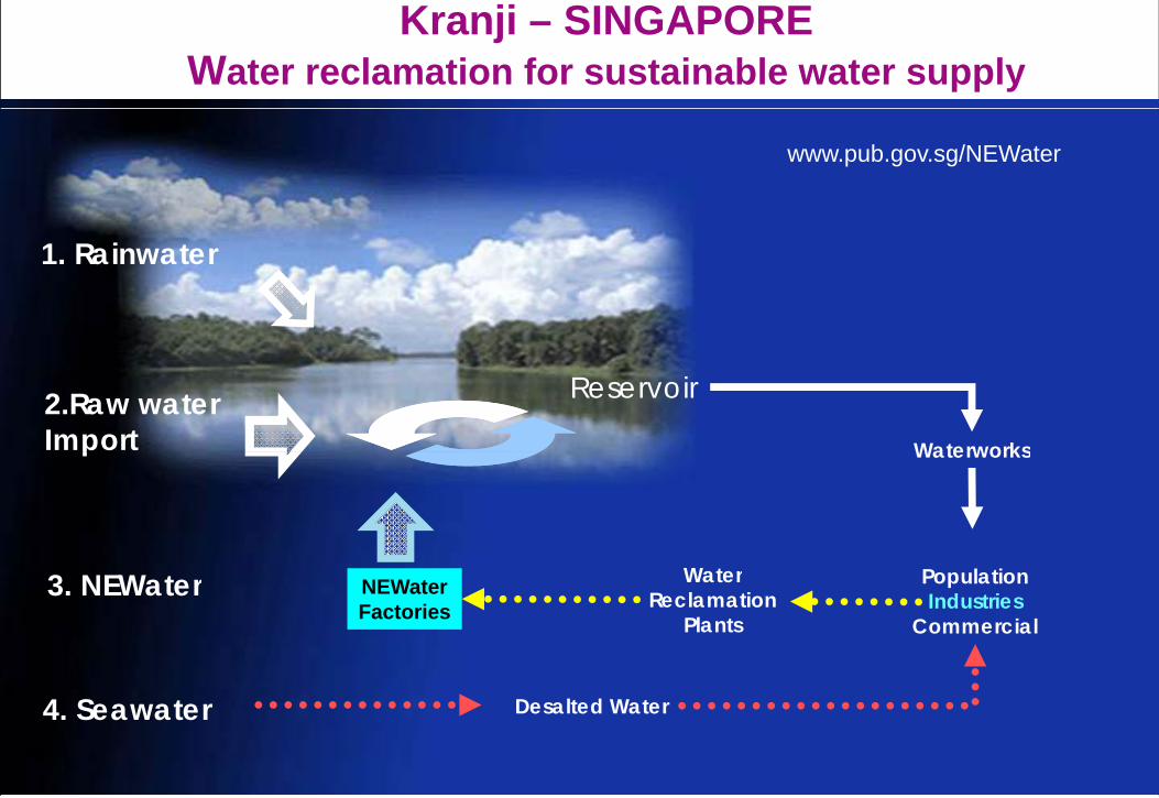
Kranji – SINGAPOREWater reclamation for sustainable water supply
www.pub.gov.sg/NEWater
1. Rainwater
2.Raw water Import
Reservoir
Waterworksp Waterworks
3. NEWater PopulationIndustries
Commercial
WaterReclamation
Plants
NEWaterFactories
Desalted Water4. Seawater

First US Cities to recycle water for potable usefor potable use.
BrownwoodBig Spring
Brownwood

Types of Treatment yp
Basic Sanitary Wastewater TreatmentWater Arabia 2013

Types of Treatment
• Physical Treatment (Screening, settling, non-biological filters)- Removes debris, floatable material, coarse solids, fine solidsRemoves debris, floatable material, coarse solids, fine solids
• Chemical Treatment (Disinfection, polymer, etc.)- Combines with soluble contaminantsCombines with soluble contaminants- Coagulation of solids for separation- Disinfection
W t lit dj t t H b ff i- Water quality adjustment – pH, buffering
• Biological Treatment (Biological Filter, activated sludge, SBR, MBR)- Removes or converts biodegradable organics- Converts Ammonia and nitrogen compounds- Removes soluble Phosphates
Basic Sanitary Wastewater TreatmentWater Arabia 2013
35

Process Flow Diagram – Trickling Filter
Grit/Grease Secondary Chlorine Primary Screening Trickling FilterRemoval
Grease
yClarifier Contact
ySettling
g
Screenings
Trickling Filter
GritR i l ti
Influent Pumping
Primary Sludge
Secondary Sludge
RecirculationPumping
Basic Sanitary Wastewater TreatmentWater Arabia 2013
36

Process Flow Diagram – Activated Sludgeith T ti T t twith Tertiary Treatment
FiltrationSecondary Settling
DisinfectionPrimary Settling
Biological Treatment
Screening Grit/Grease Removal SettlingSettling Treatment
Screenings
Removal
Grease
Grit
Influent Pumping
Primary SludgeReturn Activated Sludge
Secondary Sludge
Basic Sanitary Wastewater TreatmentWater Arabia 2013
37

Process Flow Diagram – Membrane Bioreactor and UV
Grit/Grease UltravioletA ti T kScreening MembraneGrit/Grease Removal
Grease
Ultraviolet Disinfection
Aeration TankScreening
Screenings
Membrane Bioreactor
G it
TSE
Grit
Influent Pumping
Return Sludge
Basic Sanitary Wastewater TreatmentWater Arabia 2013
38

Treatment Selection
Basic Sanitary Wastewater TreatmentWater Arabia 2013

Treatment Selection
Population projections
L ti f t t t l tLocation of treatment plants
Disposal/reuse options
Value of land
Siting configurations (topography)
Basic Sanitary Wastewater TreatmentWater Arabia 2013
40

Population Projections
Highest Rate of Expansion of Growth
?
Lowest Rate of Expansion of Growth
2002 Master 2012 Master2002 Master Plan Data
2012 Master Plan Data
2002 2012 2022 20322002 2012 2022 2032

42Basic Sanitary Wastewater TreatmentWater Arabia 2013

Service Area Conditions and Expansion
Water Network Existing
Water Network Future
Sewer Network Existing
Sewer Network Future
Sewer Network Existing
TSE Network Existing
TSE Network Future

Treatment Process Considerations
There are an infinite number of configurations in wastewater treatment
Treatment Process Decisions can be affected by:
• Site Configuration and Geology
• Initial and Future Capacity
• Effluent Standards
• Automation Required
• Flexibility of Treatment
• Proximity to Development

Mass Balance
45

Hydraulic Profile
Basic Sanitary Wastewater TreatmentWater Arabia 2013

Preliminary Treatmenty
Basic Sanitary Wastewater TreatmentWater Arabia 2013

Influent Pumping/Flow MeasurementfFiltrationSecondary
SettlingDisinfectionPrimary
SettlingBiological Treatment
Grit/Grease Removal
Screening
Screenings Greaseg
Influent Pumping
Grit
Primary Sludge
Secondary Sludge
Influent Pumping sets the hydraulic profile for the treatment plant. It can provide dampened delivery of wastewater with large wetwell design and VFDs Influent pumping stations often take plant recycles
p g
VFDs. Influent pumping stations often take plant recycles.
Coarse screening ahead of pumps can remove large solids before pumping. Alternatively, grinder systems are designed to allow pumps to deliver solids to the plant headworks. Flow measurement may be provided with flumes upstream of the wetwell, or pump discharge meters.
48Basic Sanitary Wastewater TreatmentWater Arabia 2013

Influent Pumping
• Required in many plants, where plant hydraulics not available
t llnaturally• Submersible or wet well/dry well• Coarse screening frequently used• Constant speed or ariable speed• Constant speed or variable speed
pumps• Odors and odor control• Health and safetyHealth and safety
Basic Sanitary Wastewater TreatmentWater Arabia 2013
49

Pump Station Scale
Small – Less than 100 l/s Wet Well - Submersible
Medium – 100 to 300 l/s Dry Well / Wet Well
Large – Greater than 300 l/sec Dry Well
50Basic Sanitary Wastewater TreatmentWater Arabia 2013

Wet Wells
51Basic Sanitary Wastewater TreatmentWater Arabia 2013

Dry Well Installations
52Basic Sanitary Wastewater TreatmentWater Arabia 2013

Large Scale
53Basic Sanitary Wastewater TreatmentWater Arabia 2013

Influent Monitoring
• On pumped flow or in inlet works channel
• Flow monitoring with magnetic flow meter or Parshall flume
• Quality monitoring by influent sampling – Temperature, pH, TSS, BOD, Ammonia-N, alkalinityy
Basic Sanitary Wastewater TreatmentWater Arabia 2013
54

Surge Management / Control
Transient Effect Caused by:
• Power Failures
• Value Closures
• Pump Starts / Stops
55Basic Sanitary Wastewater TreatmentWater Arabia 2013

What can go wrong
56Basic Sanitary Wastewater TreatmentWater Arabia 2013

Preliminary TreatmentfFiltrationSecondary
SettlingDisinfectionPrimary
SettlingBiological Treatment
Grit/Grease Removal
Screening
Screenings Greaseg
Influent Pumping
Grit
Primary Sludge
Secondary Sludge
Preliminary treatment is required to remove inert materials that can be screened or settled from the raw sewage to prevent damage to equipment and clogging of pipes and tanks (plastics paper inert
p g
equipment, and clogging of pipes and tanks (plastics, paper, inert floatables, etc.).
Preliminary Treatment includes pre-screening ahead of pumps, fine screens, grit removal and floatable grease removal.
57Basic Sanitary Wastewater TreatmentWater Arabia 2013

Influent ScreeningS b k• Screen or bar rack
- A device with openings, generally of uniform size, that is used to retain solids - Screening element may consist of parallel bars, wire mesh, or perforated plate- Usually mechanically cleaned with automatic screenings removaly y g
• Classification of screens- Bar Racks: Screens with large openings to capture large debris which cannot be pumped - Fine screens: Common in all treatment plants to remove debris as small as cigarettes- Ultrafine screens: Used ahead of membrane treatment systems for capture of small solids that
can accumulate in a membrane system
Item Location Opening Sizep gmm
Coarse Bar Racks/Trash Ahead of Influent Pumps 24 – 72RacksFine Screens Headworks - Typical 6 - 12
Ultra Fine Screens Ahead of Membrane Systems 1 - 3y
Basic Sanitary Wastewater TreatmentWater Arabia 2013
58

Coarse Screens (Bar Racks)
• Clear openings ranging from 6 to 150 mm
• Manually or mechanically, front (upstream) or back (downstream) cleaned
• Manually cleaned screens areManually cleaned screens are usually used for small WWTPs or as standby/overflow in larger WWTPs
• V l f i d i• Volume of screenings removed is 6 – 50 l/1,000 m3
• Might not be needed if provided at the pump stations upstream from
D i P tp p p
the WWTP Design Parameters
Clear opening 25 to 44 mm
Approach Velocity 0.3 to 0.6 m/sec
Width f th b 5 t 15Width of the bar 5 to 15 mm
Basic Sanitary Wastewater TreatmentWater Arabia 2013
59

Fine Screens
• Clear openings less than 6 mm• Openings as small as 1 mmp g• Mechanically cleaned• Usually following coarse screening• Could remove up to 50% of TSS and BODp• Washing is critical for the operation
Basic Sanitary Wastewater TreatmentWater Arabia 2013
60

Band Screens: 2 - 4 mm
• Flow goes in thru center and passes thru perforations on side screens
• Screenings are carried by lifting trays and are discharged via gravity/spray into a flume above g y p ydeck level
• PE links form chains on either side to drive screen
• S i d t d i• Screenings are dewatered in a screw compactor before discharging
Basic Sanitary Wastewater TreatmentWater Arabia 2013
61

Drum Screens: 6 - 9 mm
• The screening medium is mounted on a cylinder (drum) that rotates in
fl h la flow channel• Flow goes in thru both sides and
passes thru perforations in the screen panels out of the drump
• Screenings are carried by elevating plates and are discharged via gravity/spray water into a flume Inside the drumInside the drum
• External Bypass channel required (no integral bypass)
• Screenings discharge into a g gcommon wet well and are pumped (or flow by gravity) to a liquid-solids separator unit, where they are dewatered before discharging g ginto a screenings skip
Basic Sanitary Wastewater TreatmentWater Arabia 2013
62

Alternative Drum Screen
63Basic Sanitary Wastewater TreatmentWater Arabia 2013

Screening – Design Considerations
• Size (clear openings)• Approach velocitypp y• Straight approach• Designed based on peak flow• Headloss• Head space required• Screenings handling (raking), processing and disposal• Duty and standby units• Odour control• Washing• Control (Differential headloss and timer)
Basic Sanitary Wastewater TreatmentWater Arabia 2013
64

Grit Removal
• Grit Removal is done by gravity settling or by centrifugal separation
f lidof solids• Located after bar screens and
before primary sedimentation• Types of Grit RemovalTypes of Grit Removal
- Aerated grit chamber- Horizontal settling- Vortex grit chamber
• Average grit removed is4 - 40 l/1,000 m3
Basic Sanitary Wastewater TreatmentWater Arabia 2013
65

Aerated Grit Chambers
• Air is introduced along one side of a rectangular tank to create a spiral fl tt
• Grit is removed through grab buckets
flow pattern• Heavier grit particles settle to the
bottom• Lighter particles pass through the
travelling on monorails, screw conveyor, grit pumps or airlift
• Co ers ma be req ired if releaseLighter particles pass through the tank
• Organics create odors and attract insects
• Covers maybe required if release of VOCs is a concern
• The velocity of roll governs the size of particles removed
• Normally designed to remove 0.21 mm diameter (65 mesh) or largermm diameter (65 mesh) or larger with 2-5 minute detention time at the peak hourly flow
Basic Sanitary Wastewater TreatmentWater Arabia 2013
66

Aerated Grit Chamber Design ParametersDesign Parameters
Parameters Range Typical
D t ti Ti (Mi ) t M Fl 2 5 3Detention Time (Mins.) at Max. Flow 2 - 5 3
Depth (m) 2 - 5 -
Length (m) 7 - 20 -Length (m) 7 20
Width (m) 2.5 - 7 -
Width - Depth Ratio 1:1 - 5:1 1.5 : 1
Length - Width Ratio 3:1 - 5:1 4:1
Air Supply (m3/hr./m of length) 10 – 25 -
Grit Quantities (l/1000 m3) 3.7 - 56 30
67Basic Sanitary Wastewater TreatmentWater Arabia 2013

Vortex Grit Collectors
• Flow enters/exits chamber tangentially
• Vortex induced naturally thru tangential flow and by mechanical paddle at bottom of chamber, grit migrates to center of chamber and gis stored in grit hopper
• Collector drive is on top of unit• Grit removed from grit hopper by
i t l tpumping to a cyclone separator and grit classifier
• Internal use water for grit washing• Grit pumps can be in basement orGrit pumps can be in basement or
top-mounted • Detention time ~ 30 sec range• Typically 1- 7 m in diameter and y y
2.5 – 5 m in depth
Basic Sanitary Wastewater TreatmentWater Arabia 2013
68

Vortex Design Parameters
Parameters Range TypicalDetention Time (s) 30Detention Time (s) - 30
Diameter (ft) 4 - 24 -Height (ft) 9 - 16 -
Removal Rates (%)50 mesh (0.3 mm) 95+70 mesh (0.24 mm) 85+
100 mesh (0.15 mm) 65+ -
69Basic Sanitary Wastewater TreatmentWater Arabia 2013

Grit Removal Design Considerations
• Detention time - based on peak flow• Size of particle removedp• Headloss• Grit handling (collection), dewatering and disposal• Duty and standby units• Oil and grease removal• Odor control
Basic Sanitary Wastewater TreatmentWater Arabia 2013
70

Headworks Designs
71Basic Sanitary Wastewater TreatmentWater Arabia 2013

Primary Treatmenty
Basic Sanitary Wastewater TreatmentWater Arabia 2013

Primary ClarificationfFiltrationSecondary
SettlingDisinfectionPrimary
SettlingBiological Treatment
Grit/Grease Removal
Screening
Screenings Greaseg
Influent Pumping
Grit
Primary Sludge
Secondary Sludge
Primary Treatment is the physical separation of settleable solids in rectangular settling tanks or circular clarifiers with detention time of 2
p g
rectangular settling tanks or circular clarifiers, with detention time of 2 hours or more. Settled solids are removed mechanical sludge collectors, and sludge is further treated. Floating solids are skimmed from the surface.
Basic Sanitary Wastewater TreatmentWater Arabia 2013
73

Primary Treatment• Up to 70% removal of TSS and up to 50% removal of BODUp to 70% removal of TSS and up to 50% removal of BOD• Reduce power cost associated with secondary treatment• Could be supplemented with chemical addition for enhanced
sedimentation and/or P removalsedimentation and/or P removal• Mechanically cleaned sedimentation tanks of standardized circular or
rectangular design. • Multiple tanks should be provided so that the process may remain in
Item Hydraulic Retention,
TSS Removal%
BOD removal%
Multiple tanks should be provided so that the process may remain in operation while one tank is out of service for maintenance
Retention, Hours
% %
Circular Clarifiers 2 - 3 40 – 60 20 – 30
Rectangular Clarifiers 2 3 40 60 20 30Rectangular Clarifiers 2 – 3 40 – 60 20 – 30
Lamella Clarifiers 1.5 – 2 40 – 70 25 – 40
Chemically Enhanced 1.5 - 2 50 - 75 30 – 50
74
C e ca y a cedPrimary Treatment (CEPT)
5 50 5 30 50
Basic Sanitary Wastewater TreatmentWater Arabia 2013

Rectangular Tanks
• Horizontal flow • Depth: 4 m; Width: 5 – 10 m;p
Length: 25 – 40 m• Chain-and-flight solids collectors or
traveling-bridge-type collectors
Basic Sanitary Wastewater TreatmentWater Arabia 2013
75

Circular Tanks
• Flow pattern is radial and wastewater is introduced in the center of the tankcenter of the tank
• Require larger foot print• Depth: 4 m; Diameter: 12 - 45 m
Basic Sanitary Wastewater TreatmentWater Arabia 2013
76

Lamella Clarifier/Plate Settlers
• A lamella clarifier features a rack of inclined metal plates, which cause flocculated material to precipitate fromflocculated material to precipitate from water that flows across the plates.
• Smaller footprint than conventional clarification equipment for the same solids removal capacitysolids removal capacity
• The compact design essentially eliminates any hydraulic disturbances caused by wind or temperature changes. Balanced flow distributionchanges. Balanced flow distribution ensures equal flow to each plate and across the plate surface area, preventing short-circuiting. Units and plate packs arrive at the job site factory
bl d hi h d i t ll tiassembled which reduces installation time and lowers installed costs. Minimal moving parts means low maintenance costs.
77Basic Sanitary Wastewater TreatmentWater Arabia 2013

Primary Settling Design Considerations
• Surface overflow rate (m3/m2/d) - based on peak flowTypically 80 – 120 m3/m2/d
• Baffling to reduce short circuiting• Grit handling (collection), dewatering and disposal• Duty and standby units• Odor• Pumping of primary sludge (3 -5 % solids)• Scum removal• Detention times ranging between 2 to 5 hours use a settleometer to check
how long solids can be in the clarifier without floating
Basic Sanitary Wastewater TreatmentWater Arabia 2013
78

Biological Treatment Processesg
Basic Sanitary Wastewater TreatmentWater Arabia 2013

Biological TreatmentfFiltrationSecondary
SettlingDisinfectionPrimary
SettlingBiological Treatment
(Suspended Growth)
Grit/Grease Removal
Screening
Screenings Greaseg
Influent Pumping
Grit
Primary Sludge
Secondary Sludgep g
Basic Sanitary Wastewater TreatmentWater Arabia 2013
80
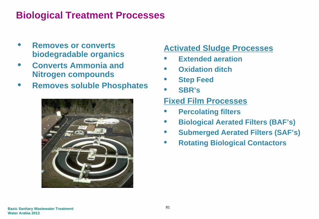
Biological Treatment Processes
• Removes or converts biodegradable organics
Activated Sludge Processes• Extended aeration• Converts Ammonia and
Nitrogen compounds• Removes soluble Phosphates
Extended aeration• Oxidation ditch• Step Feed• SBR’sFixed Film Processes• Percolating filters• Biological Aerated Filters (BAF’s)Biological Aerated Filters (BAF s)• Submerged Aerated Filters (SAF’s)• Rotating Biological Contactors
Basic Sanitary Wastewater TreatmentWater Arabia 2013
81

Activated Sludge Processesg
Basic Sanitary Wastewater TreatmentWater Arabia 2013

Activated Sludge Processes
• Activated sludge microbes (biomass) • Oxygen rich environment• Organic material in wastewater used Oxygeng
as food source• Generating growth of biomass and
clean water• Suspended growth process
Oxygen
• Suspended growth process• Biomass in free suspension to ensure
adequate contact with wastewater• Correct microbes settle well
Activated Sludge Microbe
• Settlement process allows treated effluent to be drawn off and biomass to settle
• Biomass kept alive by recycling a
c obe
Sewage• Biomass kept alive by recycling a
portion of settled biomass to activated sludge tank as growth medium to generate more biomass
• Excess bacteria removed as sludge• Excess bacteria removed as sludge
Basic Sanitary Wastewater TreatmentWater Arabia 2013
83

Activated Sludge Processes
• Many variations of activated sludge to treat municipal wastewaters• Typically follows primary sedimentation in order to reduce the solids and yp y p y
organic (BOD and COD) loading• Process includes an aeration stage followed by a settlement tank
Influent MLSS Effluent
Aeration Tank Settling Tank
Air
Surplus sludge
Recycled sludgeMLSS = Mixed Liquor Suspended Solids gMLSS Mixed Liquor Suspended Solids
Basic Sanitary Wastewater TreatmentWater Arabia 2013
84

Activated Sludge Processes
• Biomass is freely suspended in wastewater and feeds on the organic matter in the presence of oxygen
• Important operating and design parameters are HRT, MLSS, SRT, F/M, DO, SVI
• Sludge is produced as BOD is removed and needs to be removed to maintain optimum treatment conditionsoptimum treatment conditions
• The dissolved oxygen required for the process can be provided by mechanical agitation or diffused air
• Varying degrees of treatment can be achieved:y g g- Carbonaceous : BOD removal- Nitrification : Ammonia Removal- Denitrification : Nitrogen Removal
• There are many variants of the AS process which can be designed to achieve the required degree of treatment
• The sequencing batch reactor eliminates the requirement for primary and secondary settlement All processes in one tanksecondary settlement. All processes in one tank.
Basic Sanitary Wastewater TreatmentWater Arabia 2013
85

Activated Sludge Processes
Step Feed• Modification of conventional plug flow process. The feed is introduced at a p g p
number of places in the aeration tank. The concept is to even out F/M and reduce oxygen demand
E tended AerationExtended Aeration• HRT and sludge age much higher than conventional process, encouraging
greater degradation of the MLSS. Less sludge for disposal and BOD removals of 98%
Oxidation Ditch• Best known extended aeration system. Mixed liquor circulates in a
continuous channel or ‘race track’ aerated by a horizontal rotor which maintains velocity to prevent settlement
Basic Sanitary Wastewater TreatmentWater Arabia 2013
86

Typical Design Parameters
Process SRT, d F/M kgBOD/kg
Volumetric Loading
MLSS mg/L RAS % of influentg g
MLVSS-dg
kgBOD/m3-dConventional 3 -15 0.2-0.6 0.3-1.6 1500-4000 25 - 100
Conventional plug 3 15 0 2 0 4 0 3 0 7 1000 3000 25 75Conventional plug flow
3 – 15 0.2 – 0.4 0.3 – 0.7 1000 – 3000 25 - 75
Step feed 3 – 15 0.2 – 0.4 0.7 – 1.0 1500 – 4000 25 - 75
Extended aeration 20 – 40 0.04 – 0.1 0.1 – 0.3 2000 – 5000 50 - 150
Oxidation ditch 15 – 30 0.04 – 0.1 0.1 – 0.3 3000 – 5000 75 - 150
Basic Sanitary Wastewater TreatmentWater Arabia 2013
87

Activated Sludge Processes
Aeration Techniques
• Surface Aerators- Vertical shaft or Horizontal shaft- Throw activated sludge into atmosphere
as fine droplets, the contact with the air allows the mass transfer of oxygen into the liquid phase
• Diffused AirDiffused Air- Compressed air is fed in to the bottom of
the tank through fine pore diffusers. - The mass transfer of oxygen into the liquid
phase is via bubbles traveling up through the tank
Basic Sanitary Wastewater TreatmentWater Arabia 2013
88

Carbonaceous Organics Treatment
BOD + bacteria + O2 Solids + CO2 + H2O + Energy
Settled Sewage
AerobicQ Final FST
RAS
Aerobic Effluent
FST
0.8QRAS
Single Reactor Relati el Small Vol meBOD 20mg/L, COD 60mg/L, SS 30 mg/LNo reduction of Amm. N, TN, TP
Single Reactor, Relatively Small Volume
Basic Sanitary Wastewater TreatmentWater Arabia 2013
89

Biological Processes - Nitrification
Oxygen(O2)
Oxygen(O2)
Ammonia Oxidizers
(O2) (O2)
Nitrite Oxidizers
Ammonia(NH3/ NH4
+)Nitrite(NO2
- )
(Nitrosomonas) Nitrate(NO3
- )(Nitrobacter)
Autotrophic Autotrophic• Grow Faster than AmmoniaGrow Faster than Ammonia
Oxidizers• Die Out Faster• More Sensitive to InhibitionAlkalinity
(HCO3-) (H+)
Alk li it(HCO3 ) Alkalinity Destruction
Basic Sanitary Wastewater TreatmentWater Arabia 2013
90

NitrificationAmm. N (NH3) + Autotrophs + O2 Nitrite + O2 Nitrate (NO3)
Settled Sewage
FSTAerobicQ Final FSTAerobicQ
RAS
Effluent
Single Reactor Larger Vol me
1.0 QRAS
BOD 15mg/L, COD 50mg/L, SS 30mg/L, Amm.N 1mg/LSome TN, No TP reduction
Single Reactor, Larger Volume
Basic Sanitary Wastewater TreatmentWater Arabia 2013
91

Biological Processes - Denitrification
NitrogenCarbon gGas(N2)
Dioxide(CO2)
Organic Carbon Substrate
40% 60%
Nitrate Nitrite
Denitrifying Heterotrophs20-80% of Heterotrophic Bacteria
(NO3- )
Nitrite(NO2
- )
20 80% of Heterotrophic BacteriaRecovered Alkalinity(HCO3
-)
Basic Sanitary Wastewater TreatmentWater Arabia 2013
92

Denitrification
2 - 6 Q ML Recycle
Nitrate (NO3) + Heterotrophs + Carbon N2 (Gas)
Settled Sewage
FSTAerobicQ Final
2 6 Q ML Recycle
FSTAerobic QEffluent
Q RAS
BOD 15mg/L, COD 50mg/L, SS 15mg/L, Amm. N <1mg/L, TN <10mg/L, No TP reduction
Multiple Reactors, Larger Volume
g
Basic Sanitary Wastewater TreatmentWater Arabia 2013
93

Total Phosphorus Removal
PAO + Carbon P release
PAO + O2 Enhanced P uptake1Q
Settled
3-6Q ML Recycle1Q ML Recycle
Sewage
FSTAerobic Q Final
EffluentAnoxic
Q RAS
BOD 10mg/L, COD 30mg/L, SS 10mg/L, Amm. N <1mg/L, TN <10mg/L, TP 0.5 – 1.5mg/Lg
Basic Sanitary Wastewater TreatmentWater Arabia 2013
94

Advanced Activated Sludge Processes
95Basic Sanitary Wastewater TreatmentWater Arabia 2013

Sequencing Batch Reactor
Basic Sanitary Wastewater TreatmentWater Arabia 2013
96

Sequencing Batch Reactor
Basin Configuration
Basic Sanitary Wastewater TreatmentWater Arabia 2013
97
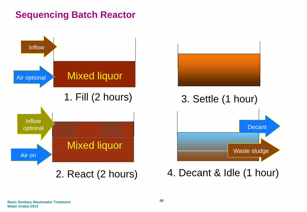
Sequencing Batch Reactor
Inflow
Mixed liquorAir optional
Inflow
1. Fill (2 hours) 3. Settle (1 hour)
Inflow optional Decant
Waste sludgeMixed liquor
2. React (2 hours)
Air on
4. Decant & Idle (1 hour)
Waste sludgeq
Basic Sanitary Wastewater TreatmentWater Arabia 2013
98

Sequencing Batch Reactor
R i d b li id d i i F ll li id l l d d i d
Effluent Decanter
Raised above liquid during aeration Follows liquid level down during decant
Basic Sanitary Wastewater TreatmentWater Arabia 2013
99

Membrane BioReactor
Basic Sanitary Wastewater TreatmentWater Arabia 2013
100

101Basic Sanitary Wastewater TreatmentWater Arabia 2013

Membrane Bioreactor
• Compact System
• No Clarifiers or Filters
• High Mixed Liquor
Concentrations Possible
• No TSS or bacteria in effluent
• Limits passage of viruses
• Small Footprint (0.3 ha/10 MLD)
• Highly automated
• Requires close monitoring
102
q g
Basic Sanitary Wastewater TreatmentWater Arabia 2013

Fixed Film Processes
Basic Sanitary Wastewater TreatmentWater Arabia 2013

What are biofilms?
A cultured biomass attached to a support medium
The biofilm develops according to the availability of particularThe biofilm develops according to the availability of particular wastewater components and will vary according to loading and configuration
Aerobic biofilms require oxygen to function
As biofilms grow via the degradation of organic compounds theyAs biofilms grow via the degradation of organic compounds they produce excess biomass which need to be removed from the system
Basic Sanitary Wastewater TreatmentWater Arabia 2013

Biofilm StructureAnaerobic AerobicAnaerobic Aerobic
O2
MediaSurface
CO2
Plastic orBiofilm Wastewater
Plastic or Rock Media
Basic Sanitary Wastewater TreatmentWater Arabia 2013

Fixed Film Reactors Fixed Film
Also known as attached growth reactors to differentiate them from activated sludge or ‘suspended growth’ systemsactivated sludge or ‘suspended growth’ systems
Biomass is cultured as a biofilm attached to a biomass support
Biofilm can be applied across the whole spectrum of wastewater treatment from low rate traditional trickling filters to ultra high rate fluidised bed reactorsfluidised bed reactors
Basic Sanitary Wastewater TreatmentWater Arabia 2013

Fixed Film Processes
• Non-submerged systems- Traditional approachTraditional approach- Biofilm wetted regularly but kept in an air environment- Developed in 1890’s as rock filters- Simple low energySimple, low energy
• Submerged systemsBi fil di hil t l t l tt d- Biofilm grows on media whilst completely wetted
- Air supplied through aeration system- High rate, small footprint- More complex with greater control required
Basic Sanitary Wastewater TreatmentWater Arabia 2013
107

Fixed Film Processes
Percolating Filters (Trickling Filters)• Non-submerged fixed film biological reactor using rock or plasticNon submerged fixed film biological reactor using rock or plastic
packing over which wastewater is distributed continuously• Advantages
- No aeration costs- Simple to operate- Robust- Known process- Long-term experience
Basic Sanitary Wastewater TreatmentWater Arabia 2013
108

Fixed Film Processes
• Percolating Filters (Trickling Filters)
• Media Properties- High surface area – maximum
biofilm attachment- Voids large pores for aeration- Voids – large pores for aeration- Non – toxic – biofilm growth- Strength – no crushing- Cost – Cheapp
• Distribution- Distribute wastewater evenly
over filter2 or 4 arms- 2 or 4 arms
- 30 – 55 mins / revolution- Improved BOD removal- Insect controlInsect control- Hydraulic, motorized or static
Basic Sanitary Wastewater TreatmentWater Arabia 2013
109

Fixed Film Processes
• Rotating Biological Contactors- More suitable for small worksMore suitable for small works- Very low power requirement- Easily covered- Mechanically simpleMechanically simple- Expensive- Tend to have mechanical problems- UnreliableUnreliable
Basic Sanitary Wastewater TreatmentWater Arabia 2013
110

Biological Aerated Filter (BAF)
Attached Growth Biological Effluent
Media RetentionProcess EffluentRetention System
Upward Flow Through a Granular Media
Filter Media
• Media - Surface for denitrifying organisms Media
Support• Media - Solids removal
Support System
Scour Air Grid
InfluentInfluent Distribution Chamber
Basic Sanitary Wastewater TreatmentWater Arabia 2013

Biological Aerated Filter (BAF)
Kruger Biostyr IDI Biofor
Air Scour PipingAir Scour Piping
Basic Sanitary Wastewater TreatmentWater Arabia 2013

Hybrid Biological Systemsy g y
Basic Sanitary Wastewater TreatmentWater Arabia 2013
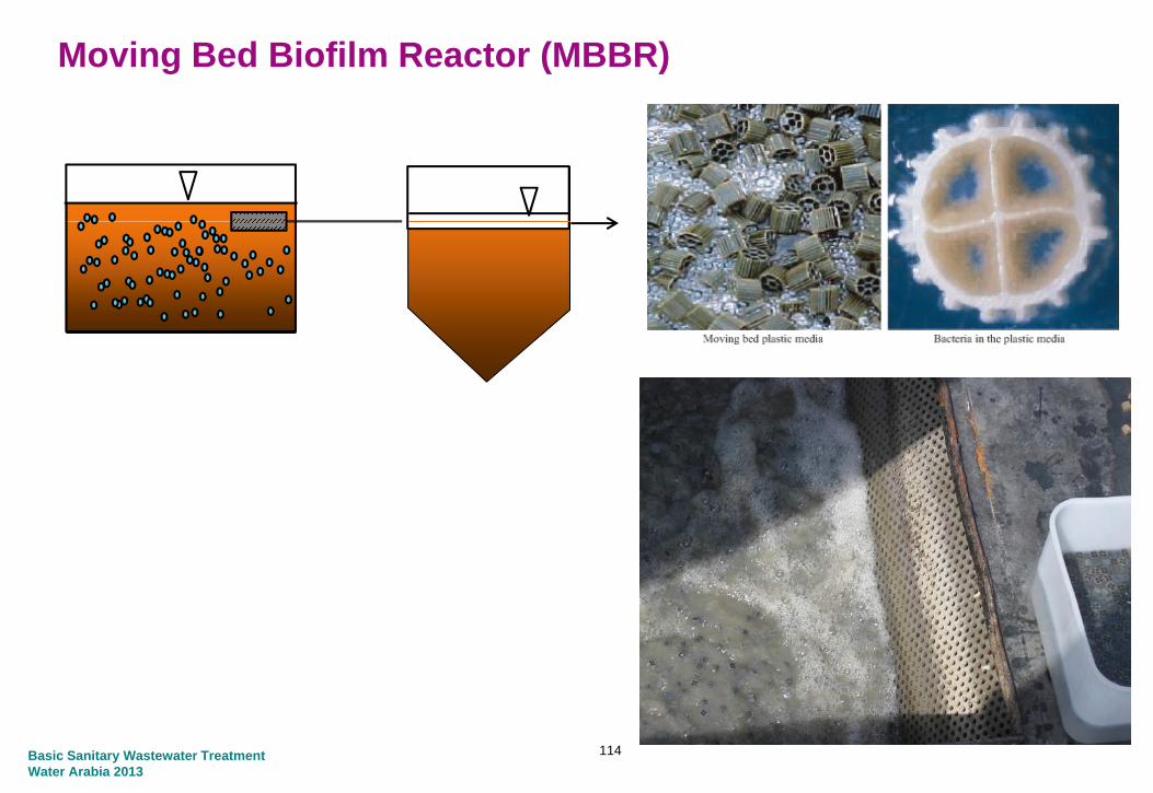
Moving Bed Biofilm Reactor (MBBR)
114Basic Sanitary Wastewater TreatmentWater Arabia 2013

Integrated Fixed Film Activated Sludge
115Basic Sanitary Wastewater TreatmentWater Arabia 2013

Secondary Clarificationy
Basic Sanitary Wastewater TreatmentWater Arabia 2013

Secondary Clarification
• Tanks in which settleable solids from the biological treatment process are separated from the wastewater
• Design considerations and tanks are similar to those used for Primary Settlement Tanks
• Most common are circular (10 to 50 m)- (10 to 50 m)
• Rectangular tanks can also be used
Basic Sanitary Wastewater TreatmentWater Arabia 2013
117

Secondary Clarification
Collectors with suction headers are the preferred type of equipment due to the nature of the sludge
Basic Sanitary Wastewater TreatmentWater Arabia 2013
118

Filtration
Basic Sanitary Wastewater TreatmentWater Arabia 2013

FiltrationfFiltrationSecondary
SettlingDisinfectionPrimary
SettlingBiological Treatment
Grit/Grease Removal
Screening
Screenings Greaseg
Influent Pumping
Grit
Primary Sludge
Secondary Sludgep g
Filtration is used to remove small solids that may leave the secondary clarifiers It is used to achieve TSS levels of less than 5 mg/Lclarifiers. It is used to achieve TSS levels of less than 5 mg/L. Microfilters and ultrafiltration can achieve TSS levels less than 1 mg/L and turbidity less than 1 NTU. Filtration can be used for tertiary treatment to remove contaminants such as phosphorus and nitrogen with
120
p p gchemicals or through biological activation.
Basic Sanitary Wastewater TreatmentWater Arabia 2013

Filtration
Types of Filtration
• Sand Filters- Gravel, sand, other granulated material- Dual multi layer or multi media filtersDual, multi layer or multi media filters
• Membranes- Ultra filters act as sievesUltra filters, act as sieves- .001- 10 micron
• Biofilm Filtration (Disc or Trickling)o t at o ( sc o c g)- Biofilter using microorganism
121Basic Sanitary Wastewater TreatmentWater Arabia 2013

Disc Filters
122Basic Sanitary Wastewater TreatmentWater Arabia 2013

Deep Bed Filters
123Basic Sanitary Wastewater TreatmentWater Arabia 2013

Low Head Filters
124Basic Sanitary Wastewater TreatmentWater Arabia 2013

Fluidized Bed Filter
125Basic Sanitary Wastewater TreatmentWater Arabia 2013

Disinfection
Basic Sanitary Wastewater TreatmentWater Arabia 2013

DisinfectionfFiltrationSecondary
SettlingDisinfectionPrimary
SettlingBiological Treatment
Grit/Grease Removal
Screening
Screenings Greaseg
Influent Pumping
Grit
Primary Sludge
Secondary Sludgep g
Disinfection removes remaining bacteria and viruses that could be harmful to fish or humans if in great concentration All TSE is disinfectedharmful to fish or humans if in great concentration. All TSE is disinfected for health reasons and to reduce bacteria growth in reuse mains. Disinfection is required ahead of disposal or reuse under most conditions. May not be required for dedicated land application,
127
y q ppsubsurface disposal or disposal to non-critical waterways.
Basic Sanitary Wastewater TreatmentWater Arabia 2013

Disinfection
Chlorination• Most commonly used
• 15 minutes contact time to remove most bacteria
• 30 minutes chlorine contact time to kill giardia cysts
Ultraviolet Radiation• 20-30 second contact time
• Inactivates viruses
• No chemical addition
• No residual disinfectant
Ozone• Strong Oxidant
128Basic Sanitary Wastewater TreatmentWater Arabia 2013

129Basic Sanitary Wastewater TreatmentWater Arabia 2013

Odour TreatmentOdour Treatment
Basic Sanitary Wastewater TreatmentWater Arabia 2013

Classification of odours
Odour threshold (ppb)
Long Term OEL (8-Hour) (ppm)
Short term OEL (15 minutes) (ppm)(pp ) ( ) (pp ) ( ) (pp )
Hydrogen Sulphide 0.5 5 10Methyl Mercaptan(methanethiol)
0.0014-18 0.5 -(methanethiol)Ethylmercaptan(ethanethiol)
0.02 0.5 2
Ammonia 130-15300 25 35Ammonia 130 15300 25 35Methylamine 0.9-53 10 -Ethylamine 2400 10 -Dimethylamine 23-80 10 -
131Basic Sanitary Wastewater TreatmentWater Arabia 2013

Why Hydrogen Sulphide
WHO guidelines for H2S.
1000-2000 ppm Immediate collapse with paralysis of respiration
530-1000 ppm Strong Central Nervous system stimulation followed by respiratory arrest
320 530 Ri k f D th320-530 ppm Risk of Death
150-250 ppm Loss of olfactory sense
50-100 ppm Serious eye damage
10-20 ppm Theshold for eye irritation
132Basic Sanitary Wastewater TreatmentWater Arabia 2013

Why Hydrogen Sulphide
The importance of Hydrogen Sulphide in odour work
• It is almost always a component of wastewater odour
• It is always a component of septic wastewater odoury p p
• It can be measured at concentrations close to its threshold
P di ti d l b d• Predictive models can be used
• In 99 cased out of 100, if the generation and release of H2S is controlled so is the odour problemcontrolled so is the odour problem.
133Basic Sanitary Wastewater TreatmentWater Arabia 2013

Methods of TreatmentA i i
Process Description Typical Design Details Typical H2S Inlet (ppm)
Typical % Removal Results
Approximate size of installation
(m3/h)Biofilters A shallow bed containing a
media such as compost or 35‐100 m3/m3.h Bed
Depth about 1m, Media Typically < 10 Maximum 50, if
70‐95% H2S Up to 95% TON, Residual
100‐15000p
peat mixed with a bulking agent such as heather on which biological growth occurs.
p ,life 2 ‐ 5 years
,irrigated
,odour about 200
OU/m3
C l ifi d A h ll b d t i i 35 100 3/ 3 h B d T i l <100 80 99% H2S 100 15000Calcified Media Biofilters
A shallow bed containing calcified media such as shells or calcified seaweed sometimes mixed with peat.
35‐100 m3/m3.h Bed Depth about 1m, Media
life 2 ‐ 5 years
Typical <100 Maximum 250,
Irrigation Required
80‐99% H2S 100‐15000
Bioscrubbers Tower packed with plastic Sizing dependent on inlet 10‐1000 60‐90% H2S, Residual 1000‐2000media on which bio‐film develops. Liquor is re‐circulated over the bed against the air flow
and required outlet concentrations (as wet scrubber) pH control
required
1 ‐ 10 ppm
Dry Chemical Impregnated particles for Dwell time 1 s <10 (has been 95 99 9% H2S with Similar toDry Chemical Scrubbers
Impregnated particles, for example of alumina, held in a bed through which odourousair passes.
Dwell time 1 s <10 (has been used for much
higher concentrations)
95‐99.9% H2S with fresh media.
Efficiency of passive units likely to be lower than this
Similar to activated carbon
1‐52000
134Basic Sanitary Wastewater TreatmentWater Arabia 2013

Process Description Typical Design Details Typical H2S Inlet (ppm)
Typical % Removal Results
Approximate size of installation
(m3/h)
d l f h h f d h b / h dActivated Carbon
Granules of high surface area carbon are held in a bed through which odourous air passes
Bed Depth about 0.25m Velocity 0.2‐0.38 m/s,
Dwell time 2s, usually 2 or 3 beds
<10 95‐99/9% H2S with fresh media.
Efficiency of passive units likely to be lower than this
Fan assisted 360‐72000 Passice
1‐1800
Catalytic Iron Filter
Iron Oxide held in a vertical or horizontal unit over which sulphide containing air passes.
500 50% 100‐15000
Wet Chemical Scrubbers
Odourous air is contacted with a flow of recirculatingliquid which dissolves and removed the odouroush l
Sizing dependent on inlet and required outlet
concentrations, pH control required
<10‐1000 95‐99% H2S 85‐95% Odour
1000‐100000
chemicals.
135Basic Sanitary Wastewater TreatmentWater Arabia 2013

Activated Carbon Filters
136Basic Sanitary Wastewater TreatmentWater Arabia 2013

Chemical Scrubbers
137Basic Sanitary Wastewater TreatmentWater Arabia 2013

Biological Treatment
138Basic Sanitary Wastewater TreatmentWater Arabia 2013

Small Treatment Systemsy
Basic Sanitary Wastewater TreatmentWater Arabia 2013
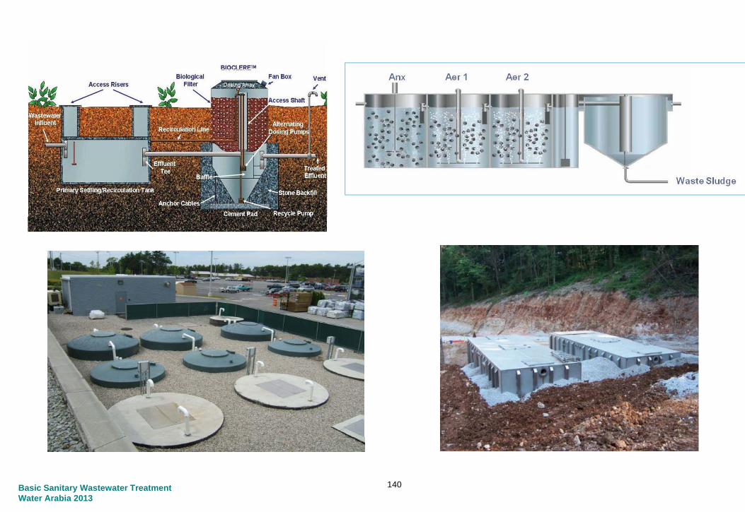
140Basic Sanitary Wastewater TreatmentWater Arabia 2013

141

142Basic Sanitary Wastewater TreatmentWater Arabia 2013

Biological Process Modelingg g
Basic Sanitary Wastewater TreatmentWater Arabia 2013

Wastewater Process Modeling Software
Basic Sanitary Wastewater TreatmentWater Arabia 2013
144

Biological Process Modeling
Different process units can be included to "build" a specific treatment plant configuration and model any conditionconfiguration and model any condition
145Basic Sanitary Wastewater TreatmentWater Arabia 2013

Screened Raw
De-Ox_1 De-Ox_2
Anoxic Aerobic 2
WAS
Aerobic 1Anaerobic
Permeate Membrane Cassette RXR
146Basic Sanitary Wastewater TreatmentWater Arabia 2013

Sludge Treatmentg
Basic Sanitary Wastewater TreatmentWater Arabia 2013

Sludge Treatment
What is Sludge?
• Wastewater sludge is comes from:• Primary Sludge: Settled solids from raw wastewater, mostly TSS, from Primary
Settling Tanks• Secondary Sludge: Live and dead bacteria from biological treatment processes,
which are settled in the Secondary Settling Tanks
148Basic Sanitary Wastewater TreatmentWater Arabia 2013

Sludge Treatment
Why treat sludge?
• Need to dispose of the sludge• Wastewater sludge smells• Contains high level of fecal bacteria
• Disposal Options• Burning• Recycle to land• Recycle to land
• Sludge from the settlement tanks is low in solids contents, concentrations between 0.5% and 2% solids.
• Treatment will concentrate the solids and reduce the volume to be disposed
• Treatment will also reduce odors and the level of fecal bacteria
149Basic Sanitary Wastewater TreatmentWater Arabia 2013

Sludge Treatment
• Thickening• Gravity Thickening• Gravity Thickening• Gravity Belt Thickening• Rotary Drum Thickening• Dissolved Air Flotation Thickening• Dissolved Air Flotation Thickening
• Digestion• Aerobic DigestionAerobic Digestion• Anaerobic Digestion
• Dewatering
• Drying
Incineration• Incineration150Basic Sanitary Wastewater Treatment
Water Arabia 2013

Sludge Treatment – Aerobic Digestion
DisposalDewateringDigestionThickening
GravitySSPS
Gravity Thickener
Centrifuge
SS
TS
To Landfill
Aerobic Digester
Belt Filter PressTo Landfill
PS – Primary SludgeSS – Secondary SludgeTS – Thickened SludgeDS – Digested Sludgeg g
Basic Sanitary Wastewater TreatmentWater Arabia 2013
151

Sludge Treatment – Anaerobic Digestion
Electricity to Plant
DigestionThickeningBiogas Storage
Biogas-powered Engine/Generator
PS
Dewatering IncinerationGravity Thickener
Anaerobic Digester
PS
CentrifugeSS
Ash to LandfillGravity Belt Thickener
Incinerator
PS – Primary SludgeSS – Secondary Sludge
Dewatered Sludge to LandSS Secondary Sludge
TS – Thickened SludgeDS – Digested Sludge
Sludge to Land Application
Basic Sanitary Wastewater TreatmentWater Arabia 2013
152

Sludge Thickeningg g
Basic Sanitary Wastewater TreatmentWater Arabia 2013

Sludge Thickening
• Gravity Thickening• Process similar to settlement tanks
in the liquid stream processin the liquid stream process• Works well for primary sludge but
can be used for secondary sludge with polymer additionwith polymer addition
• Requires cover and odor control in case of process upset
• Can increase solids from 1 5 – 2%Can increase solids from 1.5 2% to 4 – 6%
Basic Sanitary Wastewater TreatmentWater Arabia 2013
154

Sludge Thickening
• Gravity Thickening Design Parameters
Design Parameter RangeDiameter 10 – 25 mSidewater Depth 3 – 5 mpSolids Loading Rate 100 – 150 kg/m2/d (PS)
25 – 70 kg/m2/d (Combined PS & SS)Hydraulic Overflow Rate 15.5 – 31 m3/m2/d (PS)Hydraulic Overflow Rate 15.5 31 m /m /d (PS)
6 – 12 m3/m2/d (Combined PS & SS)Sludge Blanket Depth 0.5 – 2.5 m
Basic Sanitary Wastewater TreatmentWater Arabia 2013
155

Sludge Thickening
• Gravity Belt Thickening• Liquid from sludge is removed
through pores in woven plastic belt• Works well for secondary sludge• Polymer addition required for efficient
operationp• Can increase solids from 0.5 – 2% to
4 – 8%
Basic Sanitary Wastewater TreatmentWater Arabia 2013
156

Sludge Thickening
• Gravity Belt Thickening Design Parameters
Design Parameter Range
Belt Width 1 – 3 m
Solids Loading Rate 200 – 600 kg/m/hr
Hydraulic Overflow Rate 20 – 58 m3/m/hr
Polymer Dosage 3 – 7 kg of dry polymer/metric ton
Basic Sanitary Wastewater TreatmentWater Arabia 2013
157

Sludge Thickening
• Rotary Drum Thickening• Slowly rotating drum aids removal of
liquid from sludge and concentrates solids
• Liquid from sludge is removed through pores in metal screen inside drum
• Works well for both primary and secondary sludge
• Polymer addition improves efficiency• Can increase solids from 0.5 – 2% to
4 – 8%• Up to 85 m3/hr capacity
Basic Sanitary Wastewater TreatmentWater Arabia 2013
158
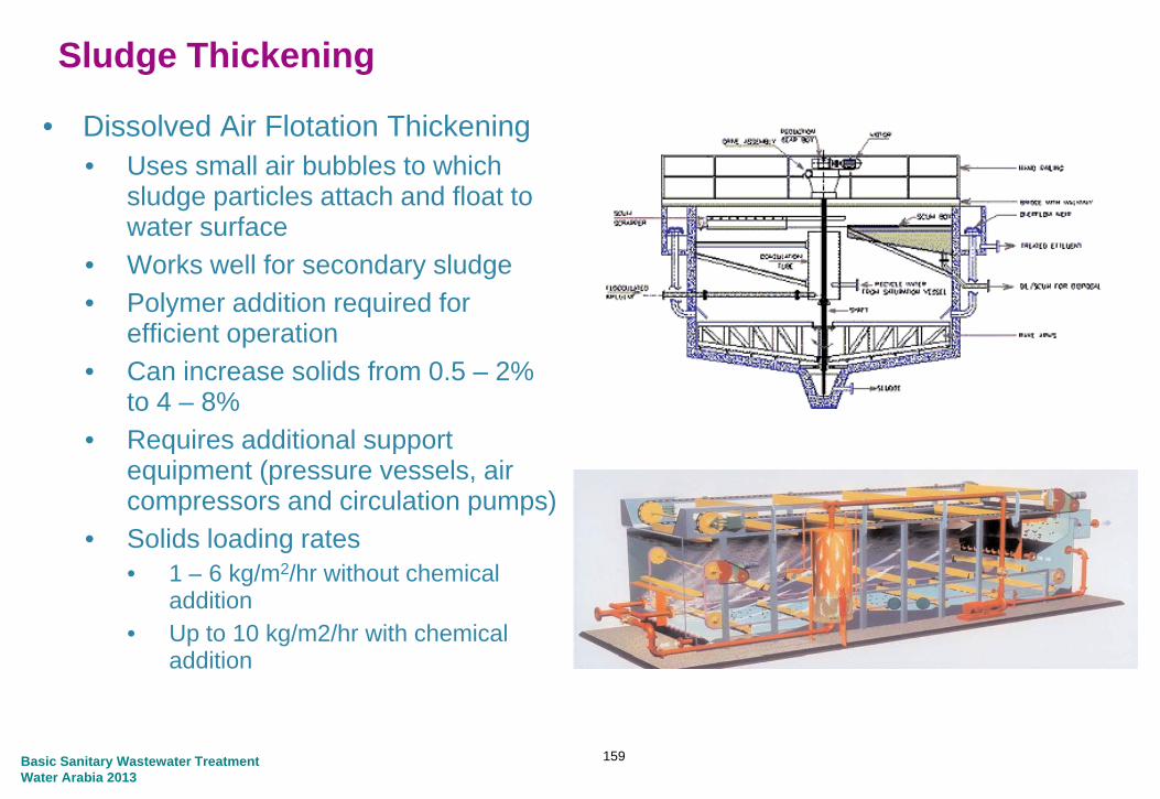
Sludge Thickening
• Dissolved Air Flotation Thickening• Uses small air bubbles to which
sludge particles attach and float to water surfacewater surface
• Works well for secondary sludge• Polymer addition required for
efficient operationefficient operation• Can increase solids from 0.5 – 2%
to 4 – 8%• Requires additional support q pp
equipment (pressure vessels, air compressors and circulation pumps)
• Solids loading rates1 6 k / 2/h ith t h i l• 1 – 6 kg/m2/hr without chemical addition
• Up to 10 kg/m2/hr with chemical addition
Basic Sanitary Wastewater TreatmentWater Arabia 2013
159

Sludge Thickening
• Centrifuge Thickener• Performance by percent capture• Liquid from sludge is removedLiquid from sludge is removed
through centrifugal action• Works well for secondary sludge• Polymer addition required forPolymer addition required for
increased solids content• Can increase solids from 0.5 – 2% to
3 – 8%
Basic Sanitary Wastewater TreatmentWater Arabia 2013
160

Digestiong
Basic Sanitary Wastewater TreatmentWater Arabia 2013

Sludge Digestion
• Process• Reduces the concentration of organic solids in sludge• Results in less sludge to process, decreases operating time and reduces
i f d t i i tsize of dewatering equipment
• Anaerobic Digestion• Uses heated sludge in a tank with a low concentration of airUses heated sludge in a tank with a low concentration of air• Process produces methane gas which can be utilized to heat the sludge and
for cogeneration• Results in varying degrees of destruction of harmful bacteria• Must be used if dewatered sludge is to be recycled
• Aerobic Digestion• Uses diffused air to reduce organic solids• Uses diffused air to reduce organic solids• Dewatered solids must be incinerated or transported to a landfill• Tanks can be either circular or rectangular
Basic Sanitary Wastewater TreatmentWater Arabia 2013
162

Egg-shaped Digesters
Basic Sanitary Wastewater TreatmentWater Arabia 2013
163
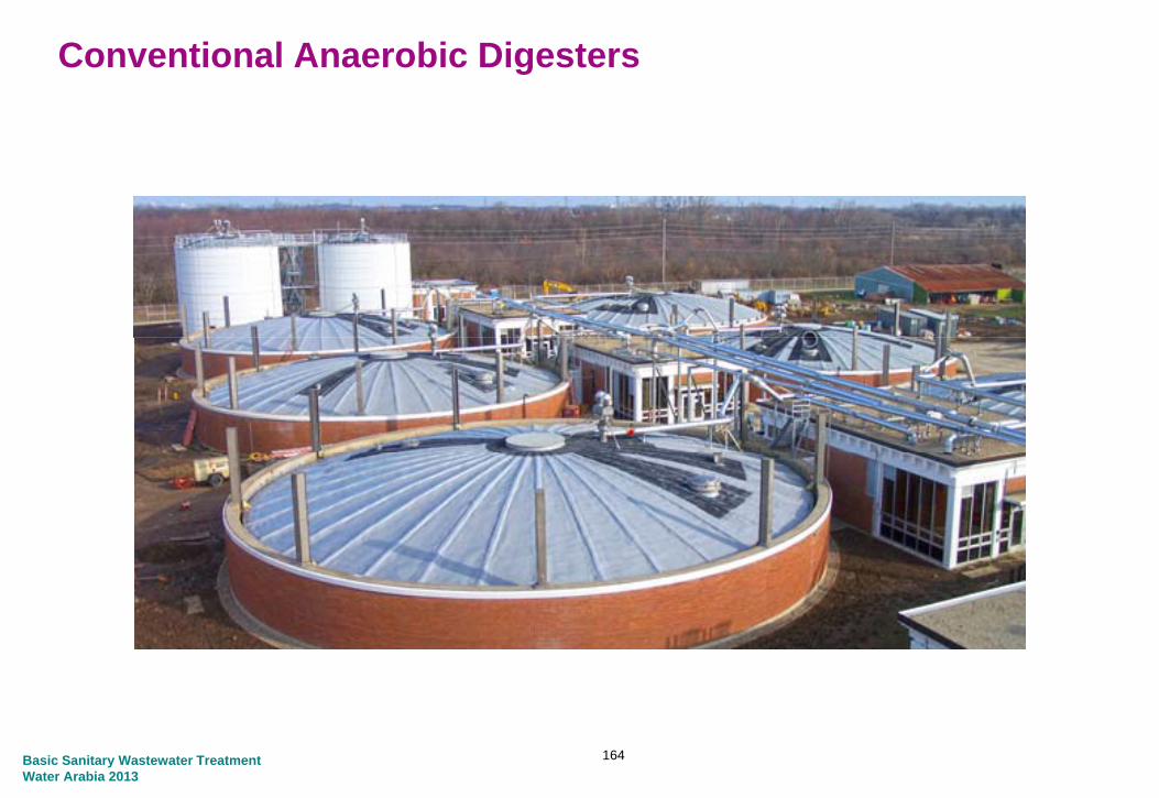
Conventional Anaerobic Digesters
Basic Sanitary Wastewater TreatmentWater Arabia 2013
164

Sludge Digestion
Anaerobic Digestion Design Parameters
• Mesophilic Process• Heated sludge temperature: 35°C• Solids retention time: 15 – 20 daysSolids retention time: 15 20 days• Solids Loading Rate: 1.6 – 4.8 kg/d/m3
• Thermophilic Process• Heated sludge temperature: 55°C• Solids retention time: 15 – 20 days
Gas
DigestedbiosolidsRaw sludge Heated
l dsludgeBasic Sanitary Wastewater TreatmentWater Arabia 2013
165

Sludge Digestion
Aerobic Digestion Design Parameters
Design Parameter Range
Volatile Solids Loading Rate 1.6 – 4.8 kg/d/m3
Solids Retention Time 40 – 60 days
Diffused Air for Mixing 0 02 – 0 04 m3/min/m3Diffused Air for Mixing 0.02 0.04 m /min/m
Basic Sanitary Wastewater TreatmentWater Arabia 2013
166

Sludge Dewateringg g
Basic Sanitary Wastewater TreatmentWater Arabia 2013

Sludge Dewatering
Centrifuge• High speed rotating drum usesHigh speed rotating drum uses
centrifugal force to remove liquid from sludge
• High capacity is a small footprint• Solids and odors are completely
contained within the drum• Produces higher dry solids content
that Belt Filter Pressthat Belt Filter Press• 70% moisture content cake
Belt Filter Press• Uses pressure to squeeze liquid
through two woven plastic belts• Requires more maintenance
70 80% i t t t k• 70-80% moisture content cake
Basic Sanitary Wastewater TreatmentWater Arabia 2013
168

Sludge Dewatering
Belt Filter Press Design ParametersDesign Parameter Range
B lt Width 0 5 3Belt Width 0.5 – 3 mFeed Rate 5 – 12 m3/hr/mSolids Loading Rate 180 – 320 kg/hr/mPolymer Dosage 4 – 10 kg of dry polymer/metric ton
Basic Sanitary Wastewater TreatmentWater Arabia 2013
169

Sludge Dewatering
• Dewatered sludge from Centrifuges and Belt Filter Presses is usually in the range of 20 – 30% dry solids
• Sludge can burned in incinerators, trucked to a landfill or used as a soil amendment if it has been adequately digestedg
Basic Sanitary Wastewater TreatmentWater Arabia 2013
170

Sludge Dewatering
Sludge Drying
– Increases Solids to 90% or greater- Reduces pathogens and vectors
In-vessel Thermal Drying Sand Bed Drying
Basic Sanitary Wastewater TreatmentWater Arabia 2013
171

Incineration
Basic Sanitary Wastewater TreatmentWater Arabia 2013

Sludge Incineration
• Burns the dewatered sludge to produce ash, reducing the volume for disposalp
• Destroys pathogens and toxic compounds making disposal saferp g p
Basic Sanitary Wastewater TreatmentWater Arabia 2013
173

Sludge Incineration
AdditiveCa(OH)2
Boilerfeed water
Steam toconsumer
Combustionair
Bag filterStackWater
Sludge
Slop oil
SNCR
ReactorFluidisedbed incinerator
p
Boiler ALC
Residuesilo
Ash silo
Oil
Basic Sanitary Wastewater TreatmentWater Arabia 2013
174

Cogenerationg
Basic Sanitary Wastewater TreatmentWater Arabia 2013

Cogeneration
• Also called Combined Heat and Power (CHP)
• Provides the opportunity to use biogas generated in Anaerobic Digestion Process
• Biogas can be collected and stored for use to:• Heat water used to maintain a suitable temperature in the digesters
to sustain biological degradation• Power combustion engines to generate electricity which powers
l itreatment plant equipment• Heat water to maintain a comfortable environment in buildings in cold
climates
Basic Sanitary Wastewater TreatmentWater Arabia 2013
176
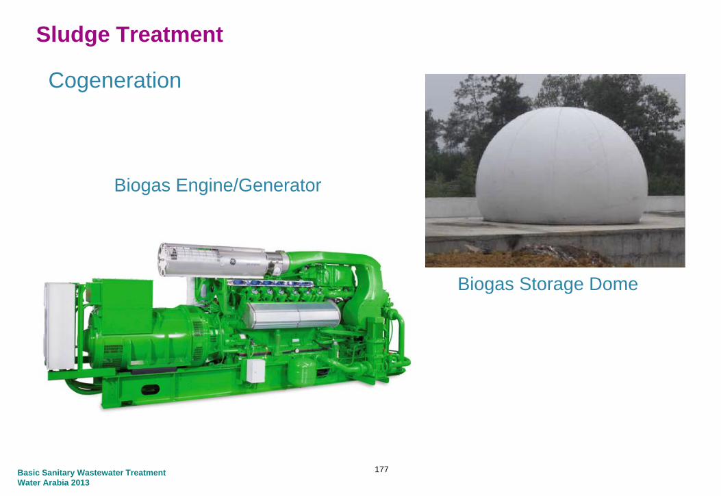
Sludge Treatment
Cogeneration
Biogas Engine/Generator
Biogas Storage DomeBiogas Storage Dome
Basic Sanitary Wastewater TreatmentWater Arabia 2013
177

Sludge Treatment gSummary
Basic Sanitary Wastewater TreatmentWater Arabia 2013

Sludge Treatment Summary
• Sewage sludge generally comprises settled solids and dead and living biomass
• It is treated to reduce volume for disposal, kill bacteria and reduce odors
• Treated sludge can be burned to further reduce the volume for disposal or g pcan be applied on land as a soil amendment
• Belt thickeners, centrifuges and belt presses are used to remove water from the sludge to thicken & dewater with the addition of polymerthe sludge to thicken & dewater with the addition of polymer
• Sludge can be digested at elevated temperature to break down the volatile solids and produce gas for power generation, producing a stable sludge for disposal
Basic Sanitary Wastewater TreatmentWater Arabia 2013
179

Thank You
Nick Cooper [email protected]
Robert B. Garner [email protected]
Basic Sanitary Wastewater TreatmentWater Arabia 2013