basic robot operation laboratory training manual
TRANSCRIPT

BasicRobotOperationMiller Training Solutions
Version 7.0
Basic Robot Operation Laboratory Training Manual

2

Training Labs
3
AbstractThis course teaches the skills required to build your product using Miller Welding Automation Industrial Equipment, from setup, to programming and debug. It includes the troubleshooting of common errors and focuses on stream lining your process with the intended outcomes of minimizing equipment down time, minimizing scrap and increasing productivity.
Lab Objectives
ContentsLab 1: Entering Teaching Points 4
Lab 2: Entering Teaching Points 6
Lab 3: Basic Part Programming 8
Lab 4: Editing Edit Teaching Points 10
Lab 5: Editing Exercise 12
Lab 6: Shift Weld Line Lab 13
Lab 7: Parallel Shift 14
Lab 8: Conversion W/Robot Teaching 16
Lab 9 Parallel Shift w/Robot Teaching 18
Lab 10: Short Cut Programming 20
Lab 11: Fillet Weld Lab 22
Lab 12: Initials Welding Lab 22
Lab 13: Logic Lab 23
Lab 14: Final Project 24
Lab 15: PerfomArc System Demo Run 26

4
Complete the following programs. Torch angle and tip-to-work distance are not a part of this assignment. Start the robot at the Home position and send the robot to the Home position with each program.
Use the lab part to program all four weld types. Ensure proper CTWD and tool orientations.
MOVEL
Lab 1: Entering Teaching Points

Training Labs
5
StartEnd StartEnd
Program the appropriate number of MOVEC’s to complete the circle and the eliptical.
The following program will require split-offs. Program the weld and assign split-off the correct points.

6
Complete the following programs. Torch angle and tip-to-work distance are not a part of this as-signment. Start the robot at the Home position and send the robot to the Home position with each program. Use the lab part to program all four weld types. Ensure proper CTWD and tool orientations. Change the frequency and travel speed of the weave to closely match the diagram. (Note: You do not have to patch the pattern perfectly.)
MOVELW
Lab 2: Entering Teaching Points Weave

Training Labs
7
MOVECW

8
Lab 3: Basic Part Programming
Lab 2 requires the user to program a linear, circle, circle weave and linear weave welds using the CRAW-T exam part.
Objective: At the end of this lab users will be able to:
• Program using proper wire stickout
• Orient robot correctly for proper weld outcomes
• Enter approach and clearance points for each weld
• Use the Trace function to walk through program
• Use the Test function to run program
Step Guidelines Parameters Status
1 Program Home point N/A
2 Program approach points and clear-ance points for each weld
Approach points and clearance points should be at least 30mm away from the weld.
3 Program all weld line according to the diagram
4 Trace through the program N/A
5 Run the program in Test mode Ensure the Arc is locked
Complete ________

Training Labs
9
Weave Side
No Weave Side
No W
eld

10
Lab 4: Editing Edit Teaching Points
Use the part from the moving exercise to program the following. Switch the Edit Type to ‘Change’ and up-dated the points as instructed. Select the appropriate response when prompted to shift the weld section.
1. Program the weld line. Do not program home.
2. Use the change feature to up-date all four points.
3. Move the approach point and weld start to the original position.
4. Move the end of the weld and clear point to the original position.

Training Labs
11
Use the part from the moving exercise to program the following.
• Use labels to identify each line section
• Program the Line 1, copy then paste to create line 2
• Switch Edit Type to ‘Change’ and update line two.
LABEL0001
LABEL0002

12
Cut, Copy and Paste
Create a new file and program the following line. Use the different editing functions. Ensure that the first and last points have the robot leaving and returning home.
• Copy all the lines and paste them at the end of the program
• Practice using the jog button to copy portions of the code.
• Complete the exercise by ensuring that both lines are properly programmed.
Complete ________
PART 2
Using the same program, complete the following:
• Complete the project by replacing the program with the following parameters:
• Amps: 230, Volts, 22, Speed: .45,
• Move Speeds: 125,
• Approach Speeds: 3
Complete ________
Lab 5: Editing Exercise
LABEL0001
LABEL0002

Training Labs
13
LABEL0001
LABEL0002
LABEL0003
LABEL0004
Lab 6: Shift Weld Line Lab
Create the original line. Use the copy and paste function to create three additional lines in the program. Update the program by shifting the weld appropriately and adding new points where necessary. Save the program.
Requirements
• Label Each Weld Line
• Use Replace Function: Amps: 230, Volts, 22, Speed: .45, Move Speeds: 125, Approach Speeds: 3
14
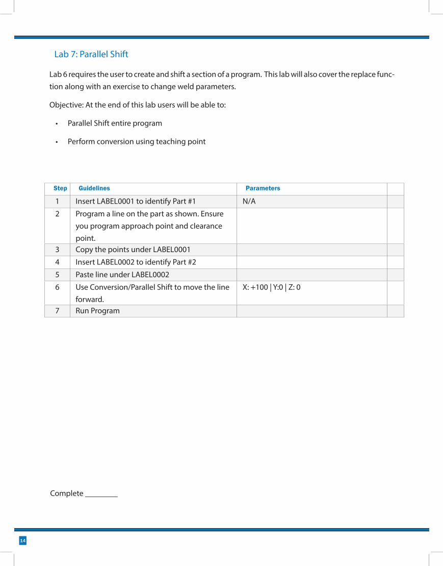
Lab 7: Parallel Shift
Lab 6 requires the user to create and shift a section of a program. This lab will also cover the replace func-tion along with an exercise to change weld parameters.
Objective: At the end of this lab users will be able to:
• Parallel Shift entire program
• Perform conversion using teaching point
Step Guidelines Parameters
1 Insert LABEL0001 to identify Part #1 N/A
2 Program a line on the part as shown. Ensure you program approach point and clearance point.
3 Copy the points under LABEL0001
4 Insert LABEL0002 to identify Part #2
5 Paste line under LABEL0002
6 Use Conversion/Parallel Shift to move the line forward.
X: +100 | Y:0 | Z: 0
7 Run Program
Complete ________

Training Labs
15
16
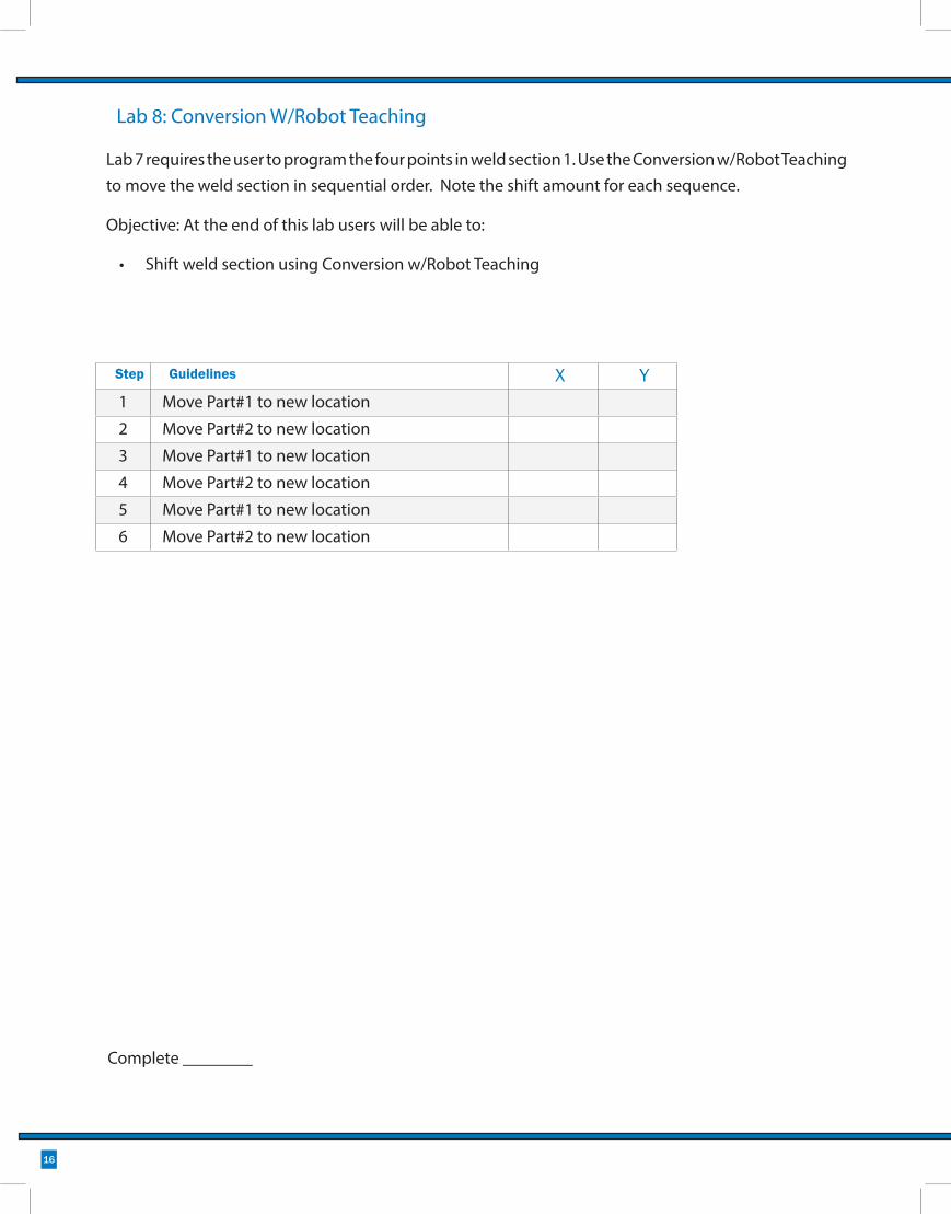
Lab 8: Conversion W/Robot Teaching
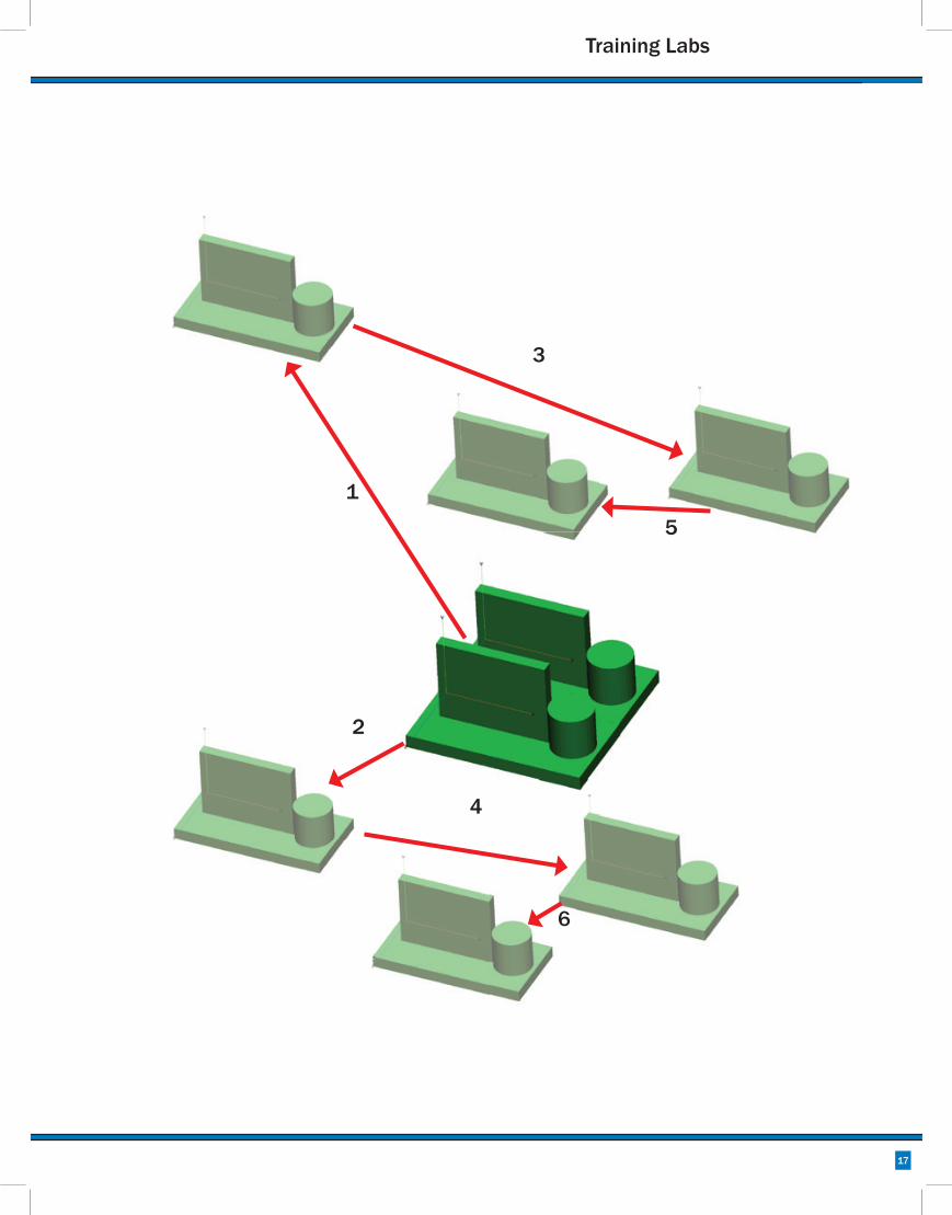
Lab 7 requires the user to program the four points in weld section 1. Use the Conversion w/Robot Teaching to move the weld section in sequential order. Note the shift amount for each sequence.
Objective: At the end of this lab users will be able to:
• Shift weld section using Conversion w/Robot Teaching
Step Guidelines X Y1 Move Part#1 to new location
2 Move Part#2 to new location
3 Move Part#1 to new location
4 Move Part#2 to new location
5 Move Part#1 to new location
6 Move Part#2 to new location
Complete ________
Training Labs
17
1
2
3
4
5
6
18
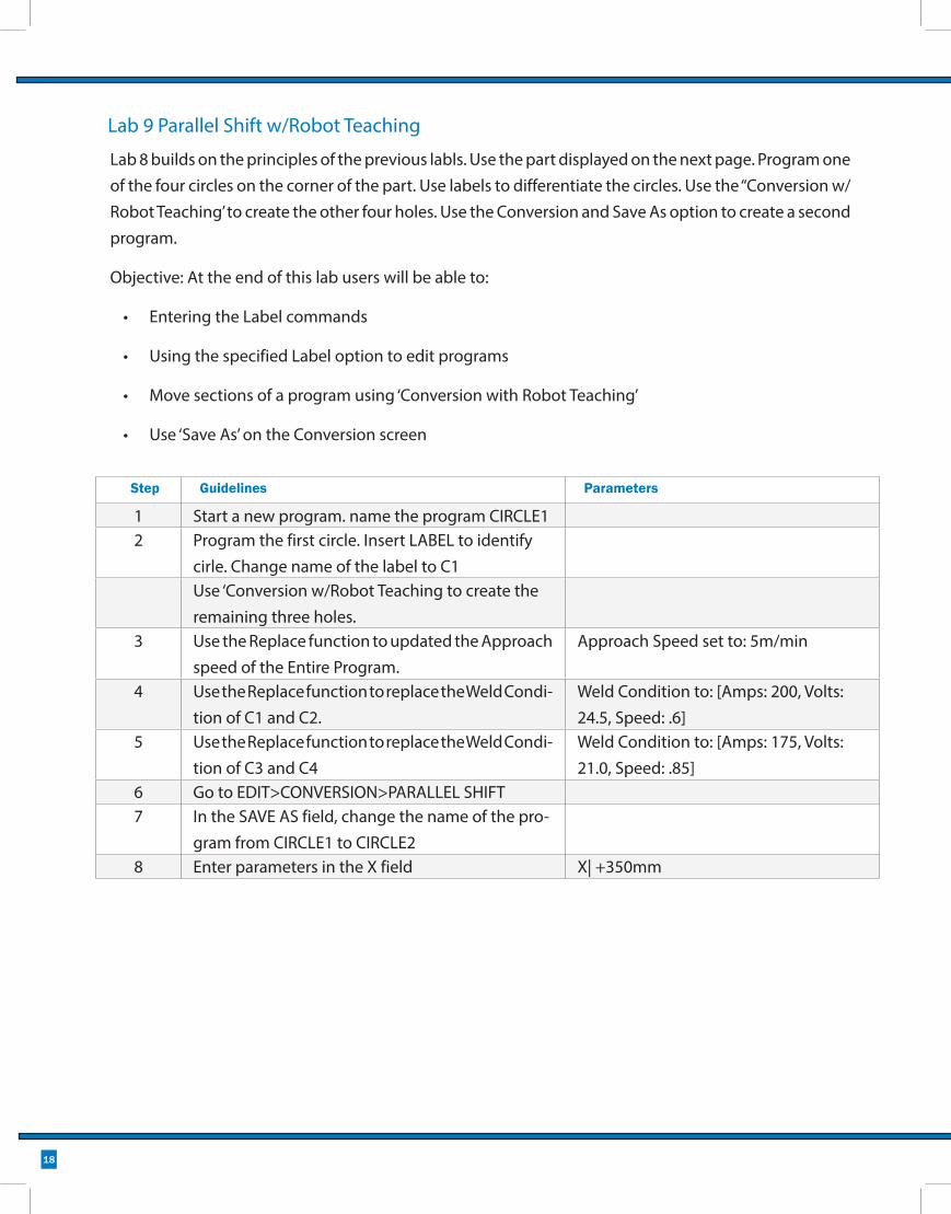
Lab 9 Parallel Shift w/Robot Teaching
Step Guidelines Parameters
1 Start a new program. name the program CIRCLE12 Program the first circle. Insert LABEL to identify
cirle. Change name of the label to C1Use ‘Conversion w/Robot Teaching to create the remaining three holes.
3 Use the Replace function to updated the Approach speed of the Entire Program.
Approach Speed set to: 5m/min
4 Use the Replace function to replace the Weld Condi-tion of C1 and C2.
Weld Condition to: [Amps: 200, Volts: 24.5, Speed: .6]
5 Use the Replace function to replace the Weld Condi-tion of C3 and C4
Weld Condition to: [Amps: 175, Volts: 21.0, Speed: .85]
6 Go to EDIT>CONVERSION>PARALLEL SHIFT7 In the SAVE AS field, change the name of the pro-
gram from CIRCLE1 to CIRCLE28 Enter parameters in the X field X| +350mm
Lab 8 builds on the principles of the previous labls. Use the part displayed on the next page. Program one of the four circles on the corner of the part. Use labels to differentiate the circles. Use the “Conversion w/Robot Teaching’ to create the other four holes. Use the Conversion and Save As option to create a second program.
Objective: At the end of this lab users will be able to:
• Entering the Label commands
• Using the specified Label option to edit programs
• Move sections of a program using ‘Conversion with Robot Teaching’
• Use ‘Save As’ on the Conversion screen

Training Labs
19
C1 C2
C3
C4
Program: CIRCLE1
C1 C2
C3
C4
Program: CIRCLE2
Shift 350mm
20
Lab 10: Short Cut Programming
Use the Right-Shift and Enter shortcut to enter the following points. Aircut points are MOVEL unless identi-fied as MOVEP. Weld points are standard MOVEL, MOVEC or MOVELW
Time Mistakes

Training Labs
21
MO
VEP
(STA
RT H
ERE)
MO
VEP
MO
VEP
MO
VEP
MO
VEP
22
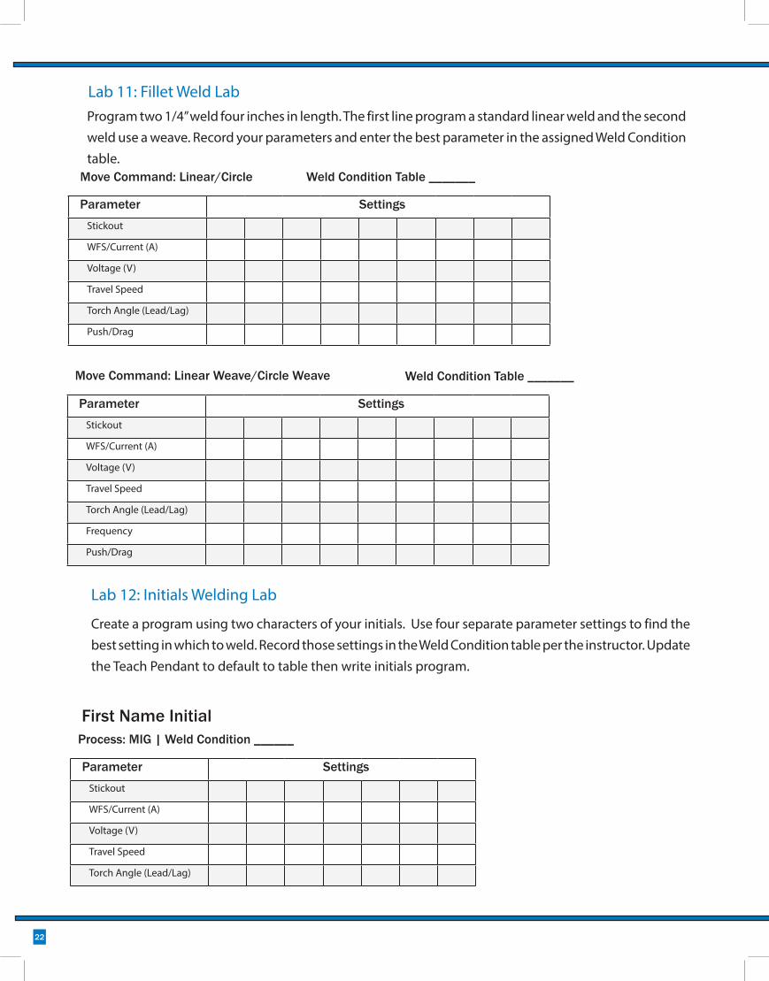
Process: MIG | Weld Condition ______
Parameter SettingsStickout
WFS/Current (A)
Voltage (V)
Travel Speed
Torch Angle (Lead/Lag)
Frequency
Push/Drag
Move Command: Linear Weave/Circle Weave
Create a program using two characters of your initials. Use four separate parameter settings to find the best setting in which to weld. Record those settings in the Weld Condition table per the instructor. Update the Teach Pendant to default to table then write initials program.
Lab 12: Initials Welding Lab
Parameter SettingsStickout
WFS/Current (A)
Voltage (V)
Travel Speed
Torch Angle (Lead/Lag)
Parameter SettingsStickout
WFS/Current (A)
Voltage (V)
Travel Speed
Torch Angle (Lead/Lag)
Push/Drag
Move Command: Linear/Circle
First Name Initial
Lab 11: Fillet Weld LabProgram two 1/4” weld four inches in length. The first line program a standard linear weld and the second weld use a weave. Record your parameters and enter the best parameter in the assigned Weld Condition table.
Weld Condition Table _______
Weld Condition Table _______

Training Labs
23
Objective: In this program you will create three weld lines. The lab requires the robot to weld the first line at least two times before moving on to weld the second line. In the program, the following commands must be present:
Create a new progam and name it your initials and the number one (example: JM1)
Use Conversion/Parallel Shift and enter 75mm in the Y-field.
Save As progam number two: example JM2
Use the same procedure to create program three and shift it 150mm on the Y axis.
Close program one and create the TC program: (TC-JM)
Move robot, enter point then insert the DELAY command. Set time to two seconds.
Lab 13: Logic Lab

24
Lab 14: Final Project
The content of the final project is left to the trainee. The parameters of the project must include:
• Full design that will fit on 6 x 6 steel plate
• Use labels to clearly define sections of the program
• At least the REM command and one CALL command
• Proper torch alignment
• Home/Origin points at the start and end of program
• Find the proper weld parameters and crater parameters and place them in a Weld Condition table
• Go to the Teach Setting menu and select the weld condition table as the default
Procedures• Plan your design, setting the proper torch angle to avoid singularity
• Test the weld parameters on scrap metal before welding project.
• Ensure proper tip-to-work distance
• Each student is limited to the use of (3) 6 x 6 plates
• Once the program is written, move the plate to the final weld desitnation
• Use the Conversion w/Robot teaching to move both programs

Training Labs
25
Process: __________ | Weld Condition ______
Parameter SettingsStickout
WFS/Current (A)
Voltage (V)
Travel Speed
Torch Angle (Lead/Lag)
Final Project Parameters
Final Project Grading Scale
CRITERIA SCORE
1. Does the program have adequate labeling? (20pts) YES NO
2. Does the project contain at least one sub-routine with a CALL command? (20pts)
YES NO
3. Is there a REM command in the program? (5pts) YES NO4. Did both programs properly align after the conversion (30pts) YES NO5. Are the Teach Setting defaults set properly? (15pts) YES NO6. Is the Weld Condition Table populated and referenced? (10pts) YES NO8. What is the total programming time taken to program? (50pts)
TOTAL SCORE

26
CRITERIA SCORE
Place the DEMO-FINAL-CRAW-A-SIDE.prg into the WELD A program and DEMO-FINAL-CRAW-B-SIDE.prg into the WELD B program.
YES NO
2. Run Tip Check program to check alignment of nozzle. YES NO3. Realign the TIPCHECK point. YES NO4. Switch system to AUTO mode and sweep table so that A-Side is at the operator side.
YES NO
5. Open the Input/Output display. Identify the follow I/O’s
I/O Name Input or Outut I/O #
Home
LDrOpen
Wire Break
Ream
YES NO
6. Switch control to AUTO and operate system in full production mode.
YES NO
7. Update the Nozzle Clean program so that it cleans the nozzle the number of cycles indentified by the instructor.
YES NO
Run the PerformArc in production mode using the following criteria.
Lab 15: PerfomArc System Demo Run