a practical humanoid robot morphology for operation in
TRANSCRIPT

109
Journal of Postgraduate Research | Trinity College Dublin | 2014
A Practical Humanoid Robot Morphology for Operation in Civilian Environments
byConor McGinn
Abstract
Despite recent progress in robotics research and development, the effective design of multi-purpose robotic solutions for civilian and domestic environments has proven particularly elusive. Mechanically simple systems are typically incapable of traversing stairs (a feature in most buildings) and lack the flexibility to undertake many tasks that may be desired while more complex solutions suffer from practical issues relating to excessive weight, size, power consumption and control complexity. The purpose of this research was to develop a hybrid robot morphology which possesses a high degree of mechanical complexity while retaining much of the control simplicity, stability and power efficiency of a conventional wheeled robot.
This paper presents the novel design of a robot morphology capable of exhibiting efficient locomotion within virtually all civilian/domestic environments and picking up objects from the ground. Through real-time control of the robot’s static stability margin, the pose of the robot has been engineered to maintain stability while reducing control complexity and energy consumption. A mathematical description of the robot’s forward kinematics is given. Practical performance capabilities of the first physical embodiment of this design are presented and future work including the implementation of a novel stair-climbing gait is discussed.

110
Journal of Postgraduate Research | Trinity College Dublin | 2014
Introduction
Personal robots1 that can reliably operate in human occupied environments (public buildings, houses, hospitals etc.) have the potential to provide unprecedented independence to people with a wide range of disabilities, the elderly and any other interest group that presently requires human assistance in order to live their everyday lives. Not only will these robots perform the types of tasks that their users are unable to but they will provide a portable, cost effective and relatively unobtrusive means of monitoring that would otherwise require a high degree of human supervision.
It is observed from the literature that correlations typically exist in the design of mobile robots between mechanical complexity, control complexity, power consumption and practical performance capability (Guizzo 2014, Hirose 1991). Robots that are mechanically simple (i.e. a 3 wheeled differentially driven robot) are also usually simple to control. Furthermore since they contain few active joints and are usually statically stable2 (i.e. they don’t require continuous power to maintain stability), they can also be said to possess a high overall energy efficiency. While such robots may seem highly desirable, their simplicity is also a limiting factor in the range of tasks that they can carry out (i.e. a simple three wheeled differentially driven robot cannot typically open a door or climb a step). As the mechanical complexity of a robot increases, so too usually does its ability to perform a wider range of tasks (i.e. a biped humanoid robot may be able to open a door and climb a step). However as such manoeuvres require close coordination of several links/joints, the problem of inverse kinematics and motion planning becomes increasingly more complex. Additionally by increasing the systems controllable degrees of freedom, the number of actuators required goes up thus raising the overall power consumption.
This paper describes the development of a novel anthropomorphic robot morphology (kinematic and dynamic configuration of a robot) which seeks to overcome the traditional relationship that exists between mechanical complexity, control complexity, energy efficiency and practical performance.
1 Personal robots refer to some form of electro-mechanical machines that operate in close proximity to/with people and possess the ability to sense and act on their environment in some way. 2 A notable exception here is self-balancing robots that use two wheels and maintain stability by adjusting the wheel velocities in response to the overall position of the centre of mass.

111
Journal of Postgraduate Research | Trinity College Dublin | 2014
The robot morphology presented in this work has been designed to be capable of performing a broad range of assistive tasks in human occupied environments (the home in particular) with relatively low levels of control complexity and power consumption when compared against existing equivalent systems. Such tasks include picking up objects from the ground and from various heights, locomotion, social interaction and stair-climbing. Therefore the primary objective of this work was to develop a high level design for a robot that is capable of multi-purpose operation in domestic and civilian environments whilst possessing good usability and high levels of stability and energy efficiency. The secondary objective of this work was to build a full-scale prototype of this morphology and to characterise several aspects of its embodiment including grasping efficiency, stability and controller performance. Methods
Related Work
The design of the proposed morphology has been influenced by a long line of preceding robot design philosophies. Humanoid robots such as Honda’s famous P-Series and Asimo series (Hirai et al. 1998), the HRP robots (Kaneko and Harada 2008, Kaneko et al. 2009) and more recently Petman/Atlas (Nelson et al. 2012, Guizzo 2014) have each demonstrated the impressive locomotive capability of bipedal robot designs. Wheeled self-balancing robots such as iBot (Ding et al. 2004), the Segway mobility platform (Nguyen and Morrell 2004) and Ball-bot (Lauwers 2006) have demonstrated that high manoeuvrability can be achieved on a statically unstable base with a large aspect ratio (ratio of robot’s height to width/depth). Additionally through the development of T-Bot (Ragusila et al. 2010) and Golem Krang (Stilman, Olson, and Gloss 2010), it was demonstrated that such systems could be designed to utilise functional manipulators and an anthropomorphic design. The PR-2 (Bohren et al. 2011) and Care-O-Bot (Connette and Parlitz 2008) have each explored how assistive domestic tasks can be undertaken through sophisticated algorithm design and a user-centered approach. The CHIMP robot developed by CMU (Guizzo 2014) to compete in the DARPA Robotics Challenge demonstrated that a level of performance in civilian environments normally reserved for statically unstable robots can be achieved on a statically stable platform that uses a hybrid form of locomotion.

112
Journal of Postgraduate Research | Trinity College Dublin | 2014
If robots are to operate in the same environments as humans, it is important that they possess some means through which they can easily and effectively communicate with people. Robots that possess social interfaces such as SPARKY (Scheeff et al. 2002), Kismet (Breazeal 1999, 2003) and Pearl (Pineau et al. 2003) have each shown that a social interface provides an intuitive, effective and easily understood mechanism through which robots can communicate with people. As social interfaces provide a continuous form of feedback to the user, their presence serves as a powerful means for people to establish their expectation of the robot’s abilities. Consequently a lack of a social interface in a robot can serve to confuse and in some cases intimidate humans in its vicinity (Schulte and Rosenberg 1999)(Green, Huttenrauch, and Norman 2000; Fong, Nourbakhsh, and Dautenhahn 2003).
A high level comparison of several of these robot platforms is presented in Table 1 and corresponding images of the robots given in Figure 1. It is noted that each robot mentioned is representative of a particular class of robot morphology.
Golem-Krang
PR-2 HRP Care-O-Bot
Robbie
Overall DOF 6 20 42 14 9Overall Default Size breadth/depth/height (mm)
<700/460/50-1500
690/670/1330-1645
695/460/1606 500/600/1400 550/600/1040
Locomotion (multiple gaits y/n)
Diff-Driven (n)
Omni (n)
Legged (n)
Omni (n)
Diff-Driven (y)
Social Interface y/n (focal point for interaction y/n) n (n) n (y) y (y) n (y) y (y)
Statically Stable y/n n y n y yRequires additional hardware to program y/n y y y y n
Table 1: A comparison of features of several state of the art robotsdeveloped for operation in civilian environment including the proposed
morphology referred to here as ‘Robbie’

113
Journal of Postgraduate Research | Trinity College Dublin | 2014
Figure 1: from left to right:Golem-Krang, the PR-2 robot, HRP-C, the Care-O-Bot robot
Figure 2: (a) A labelled diagram of the proposed morphology including the robot’s actuated degrees of freedom (in italic) (b) the coordinate system used when applying the DH method for determining the forward kinematics (c) the DH joint angles relative to the base origin. It is noted that the z-axis is located
into the page.
Mathematical Description of Robot
The proposed robot design describes a 9 degree of freedom (DOF) humanoid-type mobile robot that possesses a body, arms, head, and legs. Instead of using a walking gait for locomotion as is the case with bipedal robots, the left and right legs are rigidly fixed to each other and possess a pair of differentially driven wheels at the ankle joint (Figure 2). An actuated stabilising link which rotates about the z-axis is positioned in the shank. Actuation of this joint will cause a proportional change in the robot’s wheelbase. Through coordinated movement of the hip, knee and stabiliser joint, the robot is able to adjust its height and centre of mass (COM).

114
Journal of Postgraduate Research | Trinity College Dublin | 2014
The arms have one rotational degree of freedom at the shoulder and a prismatic joint at the elbow. Universal jamming type grippers (Amend and Brown 2012) are located at the end of each arm, both of which connect to a vacuum pump located in the robot’s body. The robot’s social interface consists of a digital LCD mounted inside a moulded robotic head. An interactive facial animation enables people to interact with the robot.
Using the Denavit-Hartenberg (DH) convention (Sprong and Vidyasagar 1989), the forward kinematics of the robot can be defined. The DH convention provides a systematic mechanism through which homogeneous coordinate transforms can be defined from the specification of just four parameters per link - link length (ai), link twist (αi), link offset (di), joint angle (θi). A transformation matrix (Ai) is generated by substituting these link parameters into a generic transform equation given by:
The DH parameters which describe a 2D projection of the robot specified are given below (Table 2). Although each base transformation matrix describes the relationship between just two coordinate systems, a larger transformation matrix can be generated by multiplying successive base transformation matrices. For example the transformation matrix which describes the position of the end-effector relative to the robot’s wheelbase (Tee) is given by:
Table 2: The DH parameters for the robot morphology
Using the segmental method, the overall COM of the robot can be computed from the cumulative position of the centre of masses of the robot’s limbs. The expression which defines this point is given by:

115
Journal of Postgraduate Research | Trinity College Dublin | 2014
Maneouverability and Stability
As domestic and civilian environments are primarily designed for use by people, it is proposed that robots possessing a similar form (i.e. a high aspect ratio and possessing legs, torso and arms) will be morphologically better suited for practical operation in such places than robots that do not. Not only are robots of this type likely to be better suited for locomotion in civilian spaces (i.e. it is challenging for robots with long wheelbases to traverse through doorways and in cluttered spaces) but they will also be able to interact with the wider environment in a more diverse and natural way, especially in instances where spatial positioning of limbs is important (engaging in social interaction with a human at eye level, picking up objects from a table etc.).
Domestic and indoor civilian environments typically possess firm and flat floor surfaces which make them well suited to locomotion for wheeled robots. The proposed robot morphology achieves locomotion through a pair of differentially driven wheels located at the base of the shank (at the ankle joint). Differentially driven robots (turning achieved by actively modifying the speed of one wheel relative to the other) have a greater degree of mobility than steered robots meaning that they can in theory follow more demanding kinematic trajectories. It is noted that to avoid the lateral turning resistance which emerges from the ground-tire interaction in skid-steered vehicles, two passive omni-directional wheels were incorporated at the end of the stabiliser link. In this instance, omni-directional wheels were deemed preferable to caster wheels as they possess a larger diameter wheel for the same overall form factor. This increased radius allows the robot to traverse bumps that would be too demanding for equivalent caster systems.
An important and novel aspect of the robot’s design is that it utilises a stability mechanism that enables it to undertake tasks previously reserved for statically unstable robots (i.e. biped legged robots) whilst retaining statically stable capabilities. During periods of rest and when engaged in locomotive tasks on hard, flat ground the robot operates in a configuration of high static stability. However when required, the robot can adopt a more upright pose through actuation of the stabiliser and knee joints and thus for the required

116
Journal of Postgraduate Research | Trinity College Dublin | 2014
time period, operate in a manner comparable with more conventional self-balancing wheeled platforms. Mathematically the stability of the robot can be quantifiably defined by its static stability margin (Armada, Estremera, and Santos 2002). The static stability margin (SSM) states that the robot is statically stable if the horizontal projection of the robot’s COM lies within its support polygon (convex polygon formed around the ground contact points of the robot) and that the margin of stability is given by the shortest straight line distance between the projection of the COM and the edges of the support polygon. For the robot described in this work, the SSM is at its maximum when the stabiliser is extended and the knees are bent (Figure 3a). However when the knees straighten and the stabiliser recoils, the shortening in the robot’s wheelbase causes the SSM to reduce (Figure 3b).
Figure 3: (a) Pose with high SSM (b) Pose with low SSM
While not accounted for in the SSM criteria, it is noted that when the robot is in an upright position, the vertical height of the COM increases and this too has the effect of decreasing the effective stability of the robot. To ensure that stable operation can be effectively maintained during less stable postural configurations, a reactive real-time controller is implemented which adjusts the wheel velocities to counterbalance any observed unexpected pitching of the robot’s body. As the joints at the wheel, knee, hip and shoulder are all constrained by the bearings to rotate in the same plane (x-y plane), it can be assumed that each joint possesses a high degree of lateral stability. A high level of lateral stability of the robot as a whole can also be expected during locomotion as the moment of inertia about the y-axis of the drive wheel is significantly larger than that about the axis of wheel rotation. Furthermore as the wheel generates significant angular momentum during locomotion, large lateral forces would be needed to induce lateral instability.

117
Journal of Postgraduate Research | Trinity College Dublin | 2014
Social Interaction
The social interface on the robot consists of a custom moulded head mounted on a 1 DOF neck (Figure 4). A monitor is mounted in the head and is in turn connected to a computer in the robot’s body which renders a dynamically responsive animated face (Figure 4a). Furthermore since this interface is connected directly to the computer controlling the robot, it can double as both a programming interface (Figure 4b) and a medium to directly communicate the robot’s internal states such as sensor readings, belief states and joint trajectory plans (Figure 4c).
Figure 4: (a) the graphical face mode(b) the programming interface mode (c) internal state visualisation mode
Several important design considerations were incorporated while designing the interface for the robot. Firstly it is clear from the work of Mori (Mori 1970) that for psychological reasons, the level of familiarity (the ‘humanness’) of the interface is something that should be regulated and that interfaces that are too ‘humanlike’ tend to illicit feelings of unease and distrust in the human user. It has been further demonstrated that in general the most agreeable interfaces retain some level of ‘robot-ness’ while also possessing some but not all human features and capabilities (Scheeff et al. 2002, Canamero 2001, DiSalvo, Gemperle and Forlizzi 2002).
Social interaction amongst humans is a complex and highly layered process whereby participants regardless of whether they know each other or not, possess a preformed mental map of the other’s mental states (desires, beliefs, feelings, intensions etc.) and as the interaction transpires, this map is dynamically updated (Dautenhahn 1999). As the mental states that human

118
Journal of Postgraduate Research | Trinity College Dublin | 2014
users will assign to robots are likely to differ from those they will assign to people, it was determined that a face alone was not a suitable mechanism to achieve effective social interaction (since information pertaining to a robots internal states is generally not easily translated to a facial expression alone). Other considerations relating to practical suitability, suitability for long term use and requirement for customisation were also incorporated when developing this interface.
Grasping
A central requirement of this design was the ability for it to pick up items from the ground. Through elongation of the arm at the prismatic joint in the elbow, a universal particle jamming gripper (Amend and Brown 2012) deforms around the object to be picked up (Figure 5). By creating a vacuum in the gripper, the gripper contracts and thus tightens around the object which can be then be safely lifted.
This type of gripper was favoured over more conventional manipulators due to its mechanical and control simplicity. As particle jamming grippers passively adapt to the shape of the object they pick up, the complex coordination between sensing, planning and actuation typically required to perform a ‘pick-up’ is substantially reduced.
Figure 5: A graphical description of the process of picking up anobject from the ground: (left) default position of robot (middle) tilt
robot forward and position gripper above object (right) elongate armand engage universal gripper to pick up object
Control
As the stability margin of the platform is something that can be dynamically

119
Journal of Postgraduate Research | Trinity College Dublin | 2014
adjusted, it is important to design the controller for poses of high and low stability. In order to avoid the computational resources required by a self-balancing algorithm, a low level subsumption architecture is implemented (Figure 6). Using rotary encoders at each joint and an inertial measurement unit (IMU) located in each limb, filters are implemented to monitor the orientation of the robot’s limbs. From this, the position of the robot’s COM is computed and the SSM is inferred. On the basis of the SSM, a PID (proportional-integral-derivative) controller adjusts the drive speed of the wheels to maintain the COM within the support polygon. A PID controller was chosen due to its computational efficiency and low system modelling requirements. The output of a PID controller is computed from the weighted sum of three gains each of which is associated with one of three system parameters: the present error (the linear distance of the COM from the support polygon), the integral of the error (sum of the previous errors since the projection of the COM fell outside the support polygon) and the derivative of the error (the rate of change of the error).
Tuning of the PID controllers, especially the controller directly responsible for wheel velocity (based on the SSM), is critical to the stability of the robot. In small scale self-balancing robots where the robot falling may not be of great concern, this can be done manually through trial and error however for larger and more complex robots simulation is necessary. In either case the proportional component is tuned first until the robot can maintain stability for several seconds, though it will oscillate considerably as the system is at best marginally stable. The integral component is then gradually increased to help reduce the overshoot and also to eliminate steady state error. The derivative control is then introduced to remove the remaining oscillations.
Figure 6: A graph of the subsumption controlarchitecture used on the robot

120
Journal of Postgraduate Research | Trinity College Dublin | 2014
Full Scale Prototype
A full scale first prototype platform has been built and tested (Figure 7). The physical properties of this robot are listed in Table 3.
Robot Sec-tion
Mass [kg]
Length [m]
Lower Leg 22.0 0.32Upper Leg 2.5 0.35
Body 10.2 0.4
Arm 1.20.625 (contracted) 0.725 (extended)
Head 1.8 0.23Table 3: A table of the robot’s key parameters
The drive wheels are powered using 12V DC CIM motors with attached spur gearboxes. The knee, hip and stabiliser joints are actuated using three identical worm drives each using identical 12V CIM motors. While the wheels, stabiliser joint and knee are actuated directly at the joint, the hip is actuated through a chain drive whose driven axis is at the knee joint. The five motor assemblies and a 12000mAh LiPo battery reside in the lower leg compartment of the robot. The decision was made to place the majority of the robot’s weight in the lower compartments in an effort to improve the static stability of the robot and to minimise the moment of inertia of the upper body. At the shoulder, the arms are each directly connected to a 360:1 planetary gearbox with an attached 12V motor which controls the swing of the arm. Due to the high gearing ratio, no control effort is generally required to maintain the position of the arms once it has picked up an object. A 12V linear actuator located inside each arm is used to extend/contract each arm at the elbow as needed and a 12V vacuum pump located inside the body is used to provide the vacuum to the universal gripping mechanism.

121
Journal of Postgraduate Research | Trinity College Dublin | 2014
Figure 7: The first prototype (left) a CAD model(right) a photo of the robot in the process of picking up a pen
Computers and sensors on-board the robot include a dual-core mini-ITX PC, a wireless router, a zigBee transceiver (“XBee ® /XBee-PRO ® RF Modules” 2009) and a custom made electronics control board. Additional sensors include five quadrature encoders (left/right wheel, stabiliser link, knee and hip), a 10 DOF inertial measurement unit (IMU) and a battery voltage sensor. The robot is tele-operated either through a custom made I-Pad app or using a simple X-Bee API that was developed primarily for testing purposes. The overall control structure is described in Figure 8.
Figure 8: The system architecture used on the robot prototype.The solid line conveys that the communication is achieved using a
wire while the dotted line represents wireless communication
The social interface on the robot consists of a custom 3D printed head mounted on a neck constructed from an aluminium-foam composite. A 7” LCD monitor is mounted in the head and is in turn connected to a computer

122
Journal of Postgraduate Research | Trinity College Dublin | 2014
in the robot’s body which renders a dynamically responsive animated face that was built through Blender software (“Blender”) (Figure 9a).
After undertaking several ‘Wizard-of-Oz’ tests where volunteers were asked to provide feedback based on a simple interaction with the robot, we found that by reducing the complexity of the animations to 5 discrete states (neutral, happy, sad, angry, surprised), people could easily understand and distinguish each state. It was further reported by the volunteers that during instances where the interface was slow to respond/react (facial features were static and animation only occurred to transition between emotions), it sometimes appeared that the computer controlling the robot may have frozen. To help alleviate this concern, the interface was made to blink at a fixed period of once every two seconds. Therefore should the computer freeze, it would be immediately apparent to the user that the computer had failed. Additionally since the robot is presently tele-operated, the blinking feature was also disabled if the computer controlling the robot lost its wireless connection. This was implemented by time stamping all received remote commands and modifying the blink function such that it would stop blinking if a defined time threshold had elapsed.
Since the computer controlling the robot interface is decoupled from the microcontrollers controlling the robot’s motion (i.e. the robot can operate without the social interface turned on), it was important to incorporate a design feature that could communicate with users to indicate that the robot was turned on. This feature was embodied as a fan which projects green light as it rotates (Figure 9b). If the robot is turned on, the fan lights up and rotates in a way that is visually evident to the user. It is noted that a fan was chosen over a static light display as it serves a double purpose of cooling the electronics located in the robot’s body.
Figure 9: (a) The emotions that can be expressed by the robot (b) the robot with the light emitting fan that indicates that the robot is turned on

123
Journal of Postgraduate Research | Trinity College Dublin | 2014
Results
The following subsections describe preliminary results obtained from conducting performance evaluation tests on the robot prototype.
Upper Body Stability
Since the hip contains a revolute joint, a controller was developed to maintain the angular position of the upper body when the robot is both at rest and in motion. The angle of the hip joint is measured using both a rotary encoder and an IMU each located at the axis of rotation of the hip. These values were passed to a Kalman filter that was designed to calculate the tilt angle of the upper body and to infer its pitching velocity and angular acceleration. Using these measurements as outputs, a PID controller was implemented which acted to maintain this angle of the upper body at a desired setpoint. Due to the large torques acting on the knee and stabiliser joints, it was not possible to test this controller on the knee or stabiliser joints.
The ability of this controller to maintain the hip joint in a constant position was evaluated as the robot underwent a typical driving task - to drive forward from rest and stop (Figure 10). The maximum deviations from the desired setpoint occur during periods of acceleration (most notably during periods of ‘starting’ and ‘stopping’) due to inertial effects. Backlash in the joint control system makes it more difficult to limit the error in the angle position, especially under dynamic conditions. This backlash was due to the use of a chain drive as well as a gearbox to transfer torque from the motor to the joint. This results in a delayed response, as the motor must turn significantly before it engages the joint. Additionally inertial effects at the joint during these periods mean that substantially higher forces are required to correct deviations from the setpoint, further delaying the response.

124
Journal of Postgraduate Research | Trinity College Dublin | 2014
Figure 10: The typical angular movement of the upper body during a‘start-stop’ cycle. In this case the travel speed between the periods
of acceleration was 0.56 m/s.
‘Start-stop’ tests of this type were conducted at 4 travel speeds, as the robot travelled forward and backwards. The maximum angular deviations from the upright position under these conditions are shown for three controllers in Figure 11. It is evident that the controller based on the angle from the IMU performed significantly better than that based on the encoder. This is due to the increased accuracy of this measurement due to the instrument’s capabilities but also the removal of backlash as a factor in angle estimation (the IMU being located on the upper-body itself). It was also observed during testing that at higher travel speeds the deviation from the desired angle increases.
Figure 11: The maximum deviations from the setpoint (vertical)of the hip joint for three controllers (encoder only, IMU only, combination
of IMU and encoder) as the robot starts from stopped, accelerates,drives and stops. The tests were repeated 4 times at each velocity
(0.47, 0.57, 0.62, 0.73 m/s) for each angle estimate method.

125
Journal of Postgraduate Research | Trinity College Dublin | 2014
The angle measurements displayed here are those calculated by theKalman filter using IMU data. An identical PID controller was used in
each case with Kp= 4, Ki=2.5, Kd= 0.04
It is imperative that this robot be able to navigate a domestic environment without small obstacles or raised surfaces (i.e. rugs, doorstops) prohibiting its operation. The robot was tested while driving over a door sill (commonly found on the threshold of a doorway) which was 12mm high and 80 mm in length. Figure 12 shows that the response of the upper body (in terms of angular deviation from the vertical) as it traverses the obstacle for three controllers (one using angle estimates from the encoder only, one using angle estimates from the IMU only and one using angle estimates from a combination of the IMU and encoder). It is observed that the response is similar to that observed during the ‘start-stop’ tests with each angle measurement technique resulting in stable behaviour and a broadly similar response. Figure 12 also shows that during normal travel on flat ground (in the period 4-7s), the combined IMU/encoder angle estimation resulted in smoother, less oscillatory angle control. This improved performance can be attributed to the ability of the combined controller (which is inherently less sensitive at high frequencies than the controllers that depend on only one sensor) to dampen transient vibrations induced in the robot.
Figure 12: The angular movement of the upper body during a‘start-stop’ cycle during which it goes over a 12mm high door sill.The angle measurements displayed here are those calculated by
the Kalman filter using IMU data. An identical PID controller was usedin each case with Kp= 4, Ki=2.5, Kd= 0.04 and the approach speed was 0.47m/s
126
Journal of Postgraduate Research | Trinity College Dublin | 2014
Bending at Hip
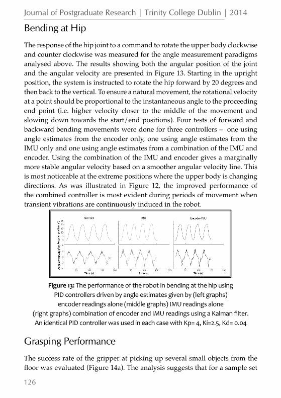
The response of the hip joint to a command to rotate the upper body clockwise and counter clockwise was measured for the angle measurement paradigms analysed above. The results showing both the angular position of the joint and the angular velocity are presented in Figure 13. Starting in the upright position, the system is instructed to rotate the hip forward by 20 degrees and then back to the vertical. To ensure a natural movement, the rotational velocity at a point should be proportional to the instantaneous angle to the proceeding end point (i.e. higher velocity closer to the middle of the movement and slowing down towards the start/end positions). Four tests of forward and backward bending movements were done for three controllers – one using angle estimates from the encoder only, one using angle estimates from the IMU only and one using angle estimates from a combination of the IMU and encoder. Using the combination of the IMU and encoder gives a marginally more stable angular velocity based on a smoother angular velocity line. This is most noticeable at the extreme positions where the upper body is changing directions. As was illustrated in Figure 12, the improved performance of the combined controller is most evident during periods of movement when transient vibrations are continuously induced in the robot.
Figure 13: The performance of the robot in bending at the hip usingPID controllers driven by angle estimates given by (left graphs)
encoder readings alone (middle graphs) IMU readings alone(right graphs) combination of encoder and IMU readings using a Kalman filter.An identical PID controller was used in each case with Kp= 4, Ki=2.5, Kd= 0.04
Grasping Performance
The success rate of the gripper at picking up several small objects from the floor was evaluated (Figure 14a). The analysis suggests that for a sample set

127
Journal of Postgraduate Research | Trinity College Dublin | 2014
of similarly sized small items, the gripper is more effective at picking up those with larger diameters. This is likely due to the larger surface area in contact with the items allowing the gripper to maximize its gripping force. Other factors could include surface roughness of the item as well as their mass. The ability of the robot to pick up an object and return it to a person was successfully demonstrated (Figure 14c).
Figure 14: (a) test objects (b) the statistical likelihood of test objectsbeing picked up. The prismatic joint in the arm was extended to push thegripper onto the object which had been placed beneath it. The vacuumpump was then turned on causing the gripper to grasp the item. After
10 seconds the prismatic joint lifted the gripper, bringing the item with it. For each item case the test was repeated 10 times (b) a handover procedure
between the robot and a user
Discussion
Throughout the period of testing, the robot demonstrated high levels of manoeuvrability on hard, flat ground. This manoeuvrability can be attributed to both its differentially driven configuration and the location of the horizontal projection of the COM. Since the overall COM tends to lie closer to the axis of the rear wheels rather than the axis of the stabiliser wheel during normal operation, the normal reaction force at the omni-wheel is reduced and therefore the build-up of lateral forces which resist turning motion is minimised.
The robot also demonstrated impressive upper body stability when stationary and when moving. The robustness of the controller was evident when the robot demonstrated the ability to remain stable in the presence of a considerable disturbance when driving over the door sill. These results serve

128
Journal of Postgraduate Research | Trinity College Dublin | 2014
to validate the effectiveness and robust nature of the PID controller which maintains the setpoint of the upper body. Furthermore it was shown that the performance of this controller is generally smoother when the upper body pitching angle estimate is taken from the combination of the rotary encoder at the hip joint and the IMU located close to the axis of rotation in the body.
Since the system is statically stable, no actuator effort was required to maintain static stability (although depending on the required pose, actuation may be required to counter inertial effects) during periods of ‘downtime’ when the robot is not actively engaged in undertaking a task. Therefore the robot can be said to be inherently more energy efficient than comparable designs which use statically unstable morphologies where continuous actuation is required in order to avoid falling over. As the control requirements of statically stable robots are inherently less than for statically unstable ones, the control and computational requirements are significantly reduced in comparison also.
It is clear from the test results that the controller succeeds in balancing the upper body during locomotion and during ‘bending over’ phases. However despite this success, the testing revealed several mechanical design improvements that would lead to a better performing robot. The first design improvement might be to increase the gearing ratio of the knee, hip and stabiliser joint. With the current design, the motors are unable to supply enough torque to extend the knee or stabiliser due to the large torques acting at these joints. This made physical testing of the controller for maintaining the SSM impossible with the current prototype. Also the rotation of the hip was limited to approximately 30 degrees as the joint torques required for recovery at greater angles became prohibitive. It is noted that during the initial testing phase, it was observed that the robot tended to oscillate about its setpoint. As the hip joint utilises low-friction rotary bearings, these oscillations were attributed to insufficient damping at the joint. These oscillations reduce significantly with the addition of an elastic rubber coupling mechanism which when installed formed an additional connection between the upper leg and the body.
It was found during testing that the gripper is extremely reliable at picking up small objects from the ground. Additionally as the inverse kinematics required to perform this task are simple, controlling a ‘pick-up’ operation via tele-operation was easy and highly intuitive. This simplicity of control contrasts greatly with conventional anthropomorphic manipulation systems

129
Journal of Postgraduate Research | Trinity College Dublin | 2014
where due to the large number of controllable DOF in the arm and hand, advanced kinematic planners are required and manual control typically requires extensive training. Tests were undertaken on larger objects (mobile phones, TV remote control etc.) and it was found that for larger objects, the reliability of the gripper reduced dramatically. Furthermore it was observed that this type of gripper suffers from a significant practical drawback in that it can only reliably pick up objects from the ground or from a surface that can apply a reaction force to the object during ‘pick-up’ in order to allow the gripper to deform around the object. Therefore while this solution provides excellent practical performance for picking up relatively small objects that have fallen to the ground, the solution will not generalise for all grasping scenarios.
While formal experiments have yet to be conducted with the social interface, it is noted from observation that the blink response which was implemented in the face has proven a highly effective means of establishing when/if the robot is connected with a host computer. It can be envisaged that when mobile robots such as the one proposed become ubiquitous in domestic environments, such an effective means of communication of non-human states will be very important in diagnosing whether a robot is malfunctioning or not. Additionally since the face can double as a programming interface and sensor visualisation suite, no external hardware (external monitor, wires, power supply etc.) other than a wireless keyboard and mouse were needed to interact fully with the robot’s main computer. This feature enables an extremely complex piece of electro-mechanical hardware to become substantially more practical than equivalent systems which require the connection of additional hardware in order to perform similar functions.
Future Work
While the physical embodiment presented in this work exhibits many of the features of the proposed robot morphology, it is expected that future prototypes will demonstrate improved performance levels and possess an increased range of features.
The limitation of the current gripper to grasp larger objects and objects from elevated surfaces (tables, shelves etc.) has been described. Research is presently being conducted on the development of an anthropomorphic robotic hand

130
Journal of Postgraduate Research | Trinity College Dublin | 2014
which it is expected to have the capability to perform these tasks. A model of this hand has been designed, built and is currently being tested (Figure 15a). While introducing such features will increase the robots capabilities, they will also increase the overall complexity (both in software and hardware) of the machine. Some features that have been incorporated in the design of the hand to minimise this added complexity include: a lightweight structure using predominantly 3D printed plastic parts, highly compliant fingers each requiring just one actuator and a fully embedded control board that can controls the fingers through a simple API. The practical importance of stair climbing ability for domestic robots is especially high considering that falls are the biggest cause of accidents in homes and stairs account for a significant proportion of such falls (Jackson and Cohen 1995). While the embodiment described does not possess stair climbing ability, it is expected that future prototypes will succeed in demonstrating this capacity. The proposed solution makes use of a two-phase gait pattern (Figure 15b). The first gait phase involves the thigh and the shank being lifted such that they rest one riser below the torso. The second gait phase involves the simultaneous extension of the arm and legs such that due to the kinematic configuration of the robot and the horizontal constraint that the stair imposes on the robot, a vertical raising movement is possible. In order to descend the stairs, a slightly modified process in reverse can be adapted. It should be clear from this description that not only does this method offer an easily controlled, stable mechanism for stair climbing but since the robot ascends and descends the stairs facing the same direction, it is simple for it to backtrack if it senses that the stairs are impassable or if instructed to do so.
Figure 15: (a) The robot gripper that will be implemented on the nextprototype (b) graphical description of the proposed stair climbing gait

131
Journal of Postgraduate Research | Trinity College Dublin | 2014
Conclusions
This paper presents the design of a novel robot morphology – one that simultaneously possesses high energy efficiency, low control complexity and an anthropomorphic form factor all arising from its ability to adjust its static stability margin. Additionally by incorporating design criteria arising from psychological considerations, the morphology is such that it’s not only capable of great behavioural diversity but it possesses the capability to engage users who may have little formal training in robotics using meaningful social interaction.
The proposed morphology may appear relatively simple in comparison to equivalent biped systems of a similar size. However due to the inherently integrated nature of the morphology, it remains one of high complexity. As well as this, with only one prototype built, the design remains at present in its relative infancy. It is clear that despite successful demonstration of core abilities including locomotion, dynamic stability and grasping, significant work is required before it can be demonstrated that an embodiment of this morphology can provide both the performance and reliability required for safe, long term use in domestic and other civilian environments.
ReferencesAmend, JR, and EM Brown. 2012. “A Positive Pressure Universal Gripper
Based on the Jamming of Granular Material.” IEEE Transatictions on Robots, Vol. 28 No. 2, 1–10. http://ieeexplore.ieee.org/xpls/abs_all.jsp?arnumber=6142115.
Armada, E García, Joaquin Estremera, and P González de Santos. 2002. “A Classification of Stability Margins for Walking Robots.” CLAWAR. http://digital.csic.es/handle/10261/8031.
“Blender”. Blender Foundation. http://www.blender.org/.
Bohren, Jonathan, Radu Bogdan Rusu, E. Gil Jones, Eitan Marder-Eppstein, Caroline Pantofaru, Melonee Wise, Lorenz Mosenlechner, Wim Meeussen, and Stefan Holzer. 2011. “Towards Autonomous Robotic Butlers: Lessons Learned with the PR2.” 2011 IEEE International Conference on Robotics and Automation (May): 5568–5575.
Breazeal, C. & Scasseiliati, B. 1999. “A Context-Dependent Attention System for a Social Robot.” Rn. Proceedings of the Sixteenth International Joint Conference on Artificial Intelligence
Breazeal, Cynthia. 2003. “Toward Sociable Robots.” Robotics and Autonomous
132
Journal of Postgraduate Research | Trinity College Dublin | 2014
Systems 42 (3-4) (March): 167–175.
Canamero, L. 2001. “I Show You How I like You-Can You Read It in My Face?” Systems, Man and Cybernetics, 31 (5): 454–459.
Connette, CP,, Parlitz, C., Graf, B., Hägele, M & Verl, A. 2008. “The Mobility Concept of Care-O-Bot 3.” 89th International Symposium on Robots
Dautenhahn, Kerstin. 1999. “Socially Intelligent Agents and the Primate Social Brain-Towards a Science of Social Minds.” Adaptive Behaviour 7 (3-4): 3–4.
Ding, Dan, Rory A. Cooper, Shojiro Terashima, Yang Yunsheng, and Rosemarie Cooper. 2004. “A Study on the Balance Function of the IBOTTM Transporter.” In RESNA 27th International Annual Confence Technology & Disability: Research, Design, Practice & Policy.
DiSalvo, CF, Francine Gemperle, and Jodi Forlizzi. 2002. “All Robots Are Not Created Equal: The Design and Perception of Humanoid Robot Heads.” Proceedings of the 4th: 321–326.
Fong, Terrence, Illah Nourbakhsh, and Kerstin Dautenhahn. 2003. “A Survey of Socially Interactive Robots.” Robotics and Autonomous Systems 42: 143–166.
Green, Anders, H Huttenrauch, and M Norman. 2000. “User Centered Design for Intelligent Service Robots.” Ninth IEEE International Workshop on Robot and Human Interactive Communication.
Guizzo, E. 2014. “Rescue-Robot Show-Down.” Spectrum, IEEE: 52–55.
Hirai, Kazuo, Masato Hirose, Yuji Haikawa, and Toru Takenaka. 1998. “The Development of Honda Humanoid Robot.” Structure: 1321–1326.
Hirose, S. 1991. “Three Basic Types of Locomotion in Mobile Robots.” Advanced Robotics “Robots in Unstructured Environments”, 91 ICAR., Fifth International Conference on: 12–17.
Jackson, Patricia L., and H.Harvey Cohen. 1995. “An in-Depth Investigation of 40 Stairway Accidents and the Stair Safety Literature.” Journal of Safety Research 26 (3) (September): 151–159.
Kaneko, Kenji, and Kensuke Harada. 2008. “Humanoid Robot HRP-3.” Intelligent Robots …: 22–26.
Kaneko, Kenji, Kanako Miura, Fumio Kanehiro, Mitsuharu Morisawa, and Shuuji Kajita Shin. 2009. “Cybernetic Human HRP-4C”: 7–14.
Lauwers, T.B. 2006. “A Dynamically Stable Single-Wheeled Mobile Robot with Inverse Mouse-Ball Drive.” Robotics and Automation, … (3): 2884–2889.
Mori, Masahiro. 1970. “The Uncanny Valley.” Energy 7 (4): 33–35.
Nelson, Gabe, Aaron Saunders, Neil Neville, Ben Swilling, Joe Bondaryk, Devin Billings, Chris Lee, Robert Playter, and Marc Raibert. 2012. “PETMAN: A

133
Journal of Postgraduate Research | Trinity College Dublin | 2014
Humanoid Robot for Testing Chemical Protective Clothing.” Journal of the Robotics Society of Japan 30 (4): 372–377. doi:10.7210/jrsj.30.372. http://japanlinkcenter.org/DN/JST.JSTAGE/jrsj/30.372?lang=en&from=CrossRef&type=abstract.
Nguyen, HG, and John Morrell. 2004. “Segway Robotic Mobility Platform.” Optics East (February 2002), 207-220.
Pineau, Joelle, Michael Montemerlo, Martha Pollack, Nicholas Roy, and Sebastian Thrun. 2003. “Towards Robotic Assistants in Nursing Homes: Challenges and Results.” Robotics and Autonomous Systems 42 (3-4) (March): 271–281.
Ragusila, Victor, Shervin Emami, John Rebula, and Tim Hutcheson. 2010. “Tbot: The Self-Balancing Transformer Robot.” http://www.shervinemami.info/tbot.html.
Scheeff, Mark, John Pinto, Kris Rahardja, and Scott Snibbe. 2002. “Experiences with Sparky, a Social Robot.” Socially Intelligent.
Schulte, J., and C. Rosenberg. 1999. “Spontaneous, Short-Term Interaction with Mobile Robots.” Robotics and Automation, 1: 658–663.
Sprong, Mark W., and M. Vidyasagar. 1989. Robot Dynamics and Control. John Wiley and Sons. 1e ed.
Stilman, Mike, Jon Olson, and William Gloss. 2010. “Golem Krang: Dynamically Stable Humanoid Robot for Mobile Manipulation.” Robotics and Automation (ICRA), … (May): 3304–3309.
“XBee ® /XBee-PRO ® RF Modules.” 2009. Digi International. https://www.sparkfun.com/datasheets/Wireless/Zigbee/XBee-Datasheet.pdf.