basic rigging safety lecture - m004 - may 2014
DESCRIPTION
Basic Rigging Safety Lecture - M004 - May 2014TRANSCRIPT

Rev5/08/2014 M_004 Bas ic Rigging Safe ty Lecture S -SA-M-006 Rev D
M_004 Basic Rigging Safety Lecture
Milton J. Shoup III Mechanical Safety Officer University of Rochester Laboratory for Laser Energetics
1 of 100

Rev5/08/2014 M_004 Bas ic Rigging Safe ty Lecture S -SA-M-006 Rev D
Safety is everyone’s business and compliance with safety procedures is MANDATORY
• If an activity or practice seems unsafe, “Stop Work” and take the time to address concerns
• Only designated or qualified personnel may attach loads to an overhead hoist
• No LLE personnel are qualified or permitted to repair rigging equipment
• Only approved/rated rigging gear shall be attached to a load hook • Load ratings shall never be exceeded • It is the riggers responsibility to ensure all components used in a
rigging operation meet the required load ratings — If a rigger is unable to determine a proper rigging configuration
contact ME or an Advanced Rigger for support
Summary
2 of 100
There are two specific roles in moving materials overhead, hoist operators and riggers
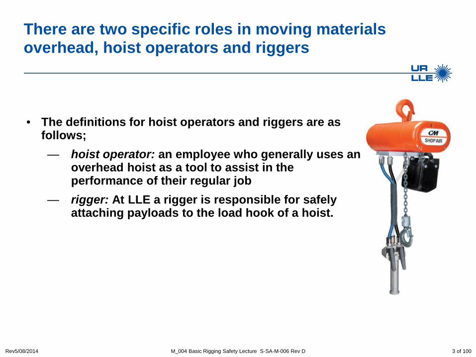
• The definitions for hoist operators and riggers are as
follows; — hoist operator: an employee who generally uses an
overhead hoist as a tool to assist in the performance of their regular job
— rigger: At LLE a rigger is responsible for safely attaching payloads to the load hook of a hoist.
Rev5/08/2014 M_004 Basic Rigging Safety Lecture S-SA-M-006 Rev D 3 of 100

Rev5/08/2014 M_004 Bas ic Rigging Safe ty Lecture S -SA-M-006 Rev D
There are two specific roles in moving material overhead, hoist operators and riggers
• There are 2 classes of training for Hoist operators — Hoist operator – for overhead vertical lifting with unpowered
horizontal motion — Overhead Crane operator – for overhead vertical lifting with
powered horizontal motion
• There are 3 classes of training for riggers — No training is required for rigging payloads <120 lbs — Basic rigger – for personnel attaching any loads from 120-500 lbs to
any hoist for a pure vertical lift — Advanced rigger – for personnel attaching any load >500 lbs to any
hoist or any load using multiple load hooks
Overhead rigging of material or equipment is to be performed only by designated personnel
4 of 100

Rev5/08/2014 M_004 Bas ic Rigging Safe ty Lecture S -SA-M-006 Rev D
Basic rigging scope of qualification
• Basic rigging training qualifies the individuals to use the following equipment; — Slings: Synthetic web slings, round and flat — Hardware: Hoist rings, eye bolts, shackles, hooks
• Basic rigging training qualifies the individuals to perform the following
activities for payloads up to 500 lbs; — Conduct rigging operations — Rig payloads for overhead lifts using the equipment listed above — Attach payloads to any load hook
5 of 100

Rev5/08/2014 M_004 Bas ic Rigging Safe ty Lecture S -SA-M-006 Rev D
OSHA Department of Labor (DOL) establishes the rules for overhead hoists
• The rules for rigging equipment are established in 29 CFR 1910.184 Slings and 29 CFR 1926.251 Rigging equipment for material handling
• The DOL incorporates additional rules by reference by citing additional standards within the regulations
• ASME B30 pertains to lifting and material-handling related equipment — There are 28 subparts to ASME B30
6 of 100
Rev5/08/2014 M_004 Bas ic Rigging Safe ty Lecture S -SA-M-006 Rev D
Purpose of the ASME B30 standard
• The B30 Standard is intended to (a) prevent or minimize injury to workers, and otherwise provide for the
protection of life, limb, and property by prescribing safety requirements
(b) provide direction to manufacturers, owners, employers, users, and others concerned with, or responsible for, its application
(c) guide governments and other regulatory bodies in the development, promulgation, and enforcement of appropriate safety directives
7 of 100

Rev5/08/2014 M_004 Bas ic Rigging Safe ty Lecture S -SA-M-006 Rev D
Numerous portions of the ASME B30 standard apply to rigging equipment
• Each of the B30 sections listed below contain requirements on the selection, use, maintenance, and inspection — B30.1 Jacks — B30.9 Slings — B30.10 Hooks — B30.20 Below-the-Hook Lifting Devices — B30.26 Rigging Hardware
• This lecture distills the ASME requirements into the policies and
practices used at LLE
8 of 100

Rev5/08/2014 M_004 Bas ic Rigging Safe ty Lecture S -SA-M-006 Rev D
The basic steps for moving a payload
1) Prep work a. Understand the payload b. Select the rigging gear c. Inspect all rigging gear d. Assign responsibilities
2) Attach the rigging gear to the payload 3) Attach payload to a load hook 4) Move the payload 5) Secure the payload 6) Detach the payload from a hook 7) Remove the rigging gear
9 of 100

Rev5/08/2014 M_004 Bas ic Rigging Safe ty Lecture S -SA-M-006 Rev D
A vital part of your Prep Work is knowing the payload and path of travel
• Weight — Can often be found in “notes” section of a part drawing — Calculations (volume x density) — Talk to Mechanical Engineering
• Center of Gravity
— Drawings will sometimes denote CG — Test lift to determine CG
• Path of travel
— Know that destination is clear and ready to accept the payload — Insure the path is clear of any obstructions and personnel that will
hinder movement
10 of 100

Rev5/08/2014 M_004 Bas ic Rigging Safe ty Lecture S -SA-M-006 Rev D
Select rated rigging equipment based upon the payload and how it is used
• Know the load capacity of the overhead hoists and support structures — This includes hoist(s), bridges, jibs, or gantries
• Know the load capacity of rigging hardware used in the rigging operation
— This includes the shackles, hoist rings, straps, etc.
• Know how use of the equipment affects the load rating
• Use only load rated products
• NEVER exceed the rated load capacity of any piece of rigging equipment
11 of 100

Rev5/08/2014 M_004 Bas ic Rigging Safe ty Lecture S -SA-M-006 Rev D
Rigging equipment must be inspected prior to each use to ensure that it is safe
• Hardware — Visually inspect all hardware for damage including but not limited
to screws, lifting shackles, hoist rings/lifting eyes, etc. — Look for thread damage, bent or fractured pieces, intentional or
unintentional modifications • Slings
— Visually inspect for damage or fraying — Insure load rating tag is on the sling and legible — Inspect sewn threads
Any rigging equipment that is found to be unsafe must removed from service immediately
12 of 100

Rev5/08/2014 M_004 Bas ic Rigging Safe ty Lecture S -SA-M-006 Rev D
During Prep activities, personnel assignments and responsibilities are reviewed
• Hard hat and safety glasses must be worn during all rigging operations • Make sure all personnel involved understand the purpose and the nature
of the operation • Designate specific tasks to individuals as needed • Use a ground spotter when lifting loads to upper level areas • Post a sentry or barricade to prevent personnel from walking under the
payload • Insure communication between all parties involved is clear and concise
— Example – Crane operator “Moving the load North” – Rigger “ Moving the load North aye”
• NEVER leave a suspended load unattended
13 of 100

Rev5/08/2014 M_004 Bas ic Rigging Safe ty Lecture S -SA-M-006 Rev D
Rated versus non-rated rigging hardware
• The terms “rated” and “non-rated” have specific meaning in the rigging field
• “Load Rated” products are engineered with special considerations important to lifting loads with cranes and hoists
• “Non-rated” products often look the same, but are engineered to provide the same design factors and safety features as the load rated versions
• Never use non-rated products for rigging
14 of 100

Definitions
• angle of loading: the acute angle between horizontal and the leg of the rigging, often referred to as the horizontal angle.
• designated person: a person selected or assigned by the employer or the employer's representative as being competent to perform specific duties
• hoist operator: an employee who generally uses an overhead hoist as a tool to assist in the performance of their regular job
• line pull: the tension load in a rope entering a rigging block. The term “pull” is commonly used to describe line pull.
• qualified person: a person who, by possession of a recognized degree in an applicable field, or certificate of professional standing, or who, by extensive knowledge, training, and experience, has successfully demonstrated the ability to solve or resolve problems relating to the subject matter and work.
Rev5/08/2014 M_004 Basic Rigging Safety Lecture S-SA-M-006 Rev D 15 of 100
Definitions
• rated load: the maximum allowable working load established by the rigging hardware manufacturer. The terms "rated capacity" and "working load limit (WLL)" are commonly used to describe rated load.
• rigger: At LLE a rigger is responsible for safely attaching payloads to the load hook of a hoist.
Rev5/08/2014 M_004 Basic Rigging Safety Lecture S-SA-M-006 Rev D 15 of 100

Rev5/08/2014 M_004 Bas ic Rigging Safe ty Lecture S -SA-M-006 Rev D
Synthetic slings
16 of 100

Rev5/08/2014 M_004 Bas ic Rigging Safe ty Lecture S -SA-M-006 Rev D
Synthetic slings are used with three basic hitch styles
• Sling ratings are specified for each of three basic styles; vertical, choker, and basket
• For the basket style hitch, the load rating is specified for a 90° sling angle
Load
17 of 100

Rev5/08/2014 M_004 Bas ic Rigging Safe ty Lecture S -SA-M-006 Rev D
Synthetic slings come in two basic Styles
• Endless Loop ( EN)
• Eye and Eye (EE)
— Type 3 Flat eye is the most popular for all three hitch styles
— Type 4 Twisted eye is more commonly used for choker hitch
18 of 100

Rev5/08/2014 M_004 Bas ic Rigging Safe ty Lecture S -SA-M-006 Rev D
Only synthetic slings are to be used at LLE
• Slings are made of either Polyester or Nylon • Various widths are available – at LLE most are from 1” to 3” wide • Information sewn into the sling label includes;
— Manufacturers' name — Serial number — Load ratings (per hitch style) — Material — Length — Sling Type — Material
19 of 100

Rev5/08/2014 M_004 Bas ic Rigging Safe ty Lecture S -SA-M-006 Rev D
Synthetic web slings shall be immediately removed from service if any of the following conditions exist
• Burn Damage from either heat or chemical sources — Heat damage may not be obvious — Any synthetic sling exposed to temperatures above 150 °F must be
removed from service
20 of 100

Rev5/08/2014 M_004 Bas ic Rigging Safe ty Lecture S -SA-M-006 Rev D
Synthetic web slings shall be immediately removed from service if any of the following conditions exist
• Snags, punctures, tears or cuts
• Broken or worn stitches
21 of 100
The red thread (tattletale) exposed in this example mean the sling must be removed from service. Simply remember “Red is dead”

Rev5/08/2014 M_004 Bas ic Rigging Safe ty Lecture S -SA-M-006 Rev D
Synthetic web slings shall be immediately removed from service if any of the following conditions exist
22 of 100

Rev5/08/2014 M_004 Bas ic Rigging Safe ty Lecture S -SA-M-006 Rev D
In a bridle hitch, two, three, or four single hitches are used together to hoist objects that have lifting lugs or other attachments
• Bridle hitches can be assembled from individual components (slings, shackles, hooks, etc.)
• Bridle synthetic slings are permanently assembled units consisting of a number web slings grouped together on a master link
• Bridle slings typically have 1-4 legs • Sling ends can be either eyes or various types of hooks
23 of 100

Rev5/08/2014 M_004 Bas ic Rigging Safe ty Lecture S -SA-M-006 Rev D
Sling rigging practices using a choker hitch
• Set the sling angle to >120° for a full load rating
• Improperly setting the choke can reduce the load rating by as much as 50%
Angle of choke, deg Rated Capacity, %Over 120 10090-120 8760-89 7430-59 620-29 49
24 of 100
Sling Angle

Rev5/08/2014 M_004 Bas ic Rigging Safe ty Lecture S -SA-M-006 Rev D
Sling rigging practices using a basket hitch
1000 lbs 1000 lbs 1000 lbs 1000 lbs 1000 lbs
• Remember that basket hitch ratings are for slings at 90° • The legs of a basket hitch are typically collected on a single hook • A sling angle less than 90° increases the tension (load) in the sling
25 of 100

Rev5/08/2014 M_004 Bas ic Rigging Safe ty Lecture S -SA-M-006 Rev D
Synthetic Sling Do’s and Don’ts
Do’s • Visually inspect slings for any
damage and remove from service if necessary
• Insure the safety tag is attached, legible, and has all pertinent information
• Verify load ratings per hitch style • Use “softeners” on sharp corners
as necessary
Don’ts • Do not use if any part of sling is
damaged • Do not use if the safety
information is missing or not legible
• Do not tie slings together • Do not use a sling that has been
shock loaded (remove it from service)
• Never exceed the load rating
26 of 100

Rev5/08/2014 M_004 Bas ic Rigging Safe ty Lecture S -SA-M-006 Rev D
Is this sling safe to use? No the red tattletale is showing
27 of 100

Rev5/08/2014 M_004 Bas ic Rigging Safe ty Lecture S -SA-M-006 Rev D
The three primary pieces of rigging hardware used at LLE
• Swivel Hoist rings • Eyebolts
• Shackles
28 of 100

Rev5/08/2014 M_004 Bas ic Rigging Safe ty Lecture S -SA-M-006 Rev D
Hoist rings
29 of 100

Rev5/08/2014 M_004 Bas ic Rigging Safe ty Lecture S -SA-M-006 Rev D
Hoist rings have free movement about 2 axes or Degrees of Freedom (DOF)
• This motion allows the hoist ring to always be aligned with the sling
Never use a hoist ring if the swivel or bail bind, this is an indication of damage
Bail
Swivel
30 of 100

Swivel hoist rings are able to accommodate various use angles
• Load ratings based on: — Size
– Ring size and thread size — Material
– Commonly alloy steel or stainless steel — Thread length
– Longer length usually designed for soft metals (aluminum) – Shorter lengths can be used in ferrous metals (steel)
• Each hoist ring is load tested and comes with a factory certificate
• Many different types and sizes are available
Rev5/08/2014 M_004 Basic Rigging Safety Lecture S-SA-M-006 Rev D 31 of 100

The longer “Effective Thread Projection” that is approximately twice the thread diameter must be used for a hoist ring threaded into aluminum
Rev5/08/2014 M_004 Basic Rigging Safety Lecture S-SA-M-006 Rev D
Frame Size
HR-125 Stock No.
Working Load Limit
Torque in
Ft-Lbs
Dimensions
Weight Each Bolt Size
Effective Thread
Projection Length Radius Diameter
No. (lbs.) A B C D E F G H (lbs.) 2 1016909 2500 28 1/2 - 13 x 2.00 0.7 4.85 1.96 0.87 0.69 3.35 2.29 2.33 2 1016912 2500 28 1/2 - 13 x 2.50 1.2 4.85 1.96 0.87 0.69 3.35 2.29 2.36 2 1016920 4000 60 5/8 - 11 x 2.00 0.7 4.85 1.96 0.87 0.69 3.35 2.16 2.41 2 1016924 4000 60 5/8 - 11 x 2.75 1.45 4.85 1.96 0.87 0.69 3.35 2.16 2.47 2 1016931 5000 100 3/4 - 10 x 2.25 0.95 4.85 1.96 0.87 0.69 3.35 2.04 2.52 2 1016935 5000 100 3/4 - 10 x 2.75 1.45 4.85 1.96 0.87 0.69 3.35 2.04 2.59 3 1016942 7000 100 3/4 - 10 x 2.75 0.89 6.57 2.96 1.36 0.94 4.87 2.98 6.72 3 1016946 7000 100 3/4 - 10 x 3.50 1.64 6.57 2.96 1.36 0.94 4.87 2.98 6.81
32 of 100

• Use an allen wrench for initial installation of the hoist ring
• A torque wrench must always be used for proper installation of the hoist ring
• Never exceed the load rating
Rev5/08/2014 M_004 Basic Rigging Safety Lecture S-SA-M-006 Rev D
Hoist ring load ratings and installation torque values are stamped or etched on an installation placard located on top of the hoist ring
33 of 100

Rev5/08/2014 M_004 Bas ic Rigging Safe ty Lecture S -SA-M-006 Rev D
Hoist ring Do’s
• Visually inspect hoist rings for any damage or corrosion on threads and body
• Insure the installation placard is attached, if not remove the hoist ring from service
• Use an allen wrench for initial installation and then a torque wrench for final tightening
• Make sure the thread engagement is appropriate for the base metal the bolt is being threaded into — Approximately 1 times the diameter when threading into steel — Approximately 2 times the diameter when threading into aluminum
• Verify swivel and bail functionality after installation
34 of 100
Rev5/08/2014 M_004 Bas ic Rigging Safe ty Lecture S -SA-M-006 Rev D
Hoist ring Don’ts
• Do not use if any part of hoist ring is damaged • Do not use if placard information if missing or not legible • Do not use a hoist ring if it is not tightened to the recommended torque • Do not use if the hoist ring does not swivel • Do not use washers in between the hoist ring and mounting surface • Do not repair, replace, or modify any piece of a hoist ring • Do not use if a gap exists between the part being lifted and the hoist ring • Do not use a hook larger than the diameter of the hoist ring bail opening • Never exceed the load rating of the hoist ring
35 of 100

Rev5/08/2014 M_004 Bas ic Rigging Safe ty Lecture S -SA-M-006 Rev D
What is the WLL of this hoist ring? Zero, the threaded rod, nut, and washers are clearly not an original bolt
36 of 100

Rev5/08/2014 M_004 Bas ic Rigging Safe ty Lecture S -SA-M-006 Rev D
Eye bolts
37 of 100

Rev5/08/2014 M_004 Bas ic Rigging Safe ty Lecture S -SA-M-006 Rev D
Machinery eye bolts are not as versatile as hoist rings
• Fixed position based upon thread engagement makes them alignment sensitive when pulling at an angle
• Can accommodate thru hole applications • Load ratings are based upon are number of factors
— Size – Ring size and thread size
— Material – Commonly forged from carbon steel or stainless steel (carbon
steel and stainless steel have different load ratings for the same size)
— Use angle – Can only be used up to 45°
• Two different styles and numerous sizes available
38 of 100

Rev5/08/2014 M_004 Bas ic Rigging Safe ty Lecture S -SA-M-006 Rev D
There are two styles of eye bolts
• Plain pattern — straight vertical pulls only
• Shoulder pattern — angular pulls up to 45° from
vertical
39 of 100
Shoulder

Rev5/08/2014 M_004 Bas ic Rigging Safe ty Lecture S -SA-M-006 Rev D
Machinery eye bolts must be used with great care
• Working load limits for eye bolts are based on a straight vertical pull “in a gradually increasing manner”
• Angular pulls will significantly lower working load limits (see Shoulder Pattern) and should be avoided whenever possible
• If an angular pull is required, a properly seated Shoulder Pattern eye bolt must be used
• Loads should always be applied to eye bolts in the plane of the eye, not at an angle to this plane
• Angular pulls must never be more than a 45° pull
Working Load Limit Diameter and
Thread Straight Pull
(X) 45° Pull (Y)
Shoulder Only
1/4"-20 500 125
5/16"-18 900 225
3/8"-16 1400 350
7/16"-14 2000 500
1/2"-13 2600 650
9/16"-12 3200 750
5/8"-11 4000 1000
3/4"-10 6000 1500
7/8"-9 7000 1750
1"-8 9000 2250
1-1/8"-7 12000 2500
1-1/4"-7 15000 3750
1-1/2"-6 21000 4900
40 of 100

Rev5/08/2014 M_004 Bas ic Rigging Safe ty Lecture S -SA-M-006 Rev D
Loads must always be applied to eye bolts in the plane of the eye
• Side pull in the plane of the eye • Sling angle must not exceed 45 °
• Side pull out of the plane of the eye. This configuration must not be used
41 of 100
Flat washers may be used under the shoulder to position the plane of the eye

Rev5/08/2014 M_004 Bas ic Rigging Safe ty Lecture S -SA-M-006 Rev D
Do not reeve slings between attachment points
• Reeving introduces side pull • Although the upper sling angle is
60°, the resultant sling angle is 30°
• For 1 lbf at 60° there is also a 1 lbf lateral load. The resultant load on the eye bolt is 1.73 lbf at 30°.
1 lbf
1 lbf
1.73 lbf
42 of 100

Rev5/08/2014 M_004 Bas ic Rigging Safe ty Lecture S -SA-M-006 Rev D
Eye bolt identification markings
• Manufacturer and Size
• Eyebolts are not required to be marked with the WLL or required installation torque. The user must look up this information prior to use
• Do not use any eye bolt for rigging unless there are clearly legible identification marks
43 of 100
Rev5/08/2014 M_004 Bas ic Rigging Safe ty Lecture S -SA-M-006 Rev D
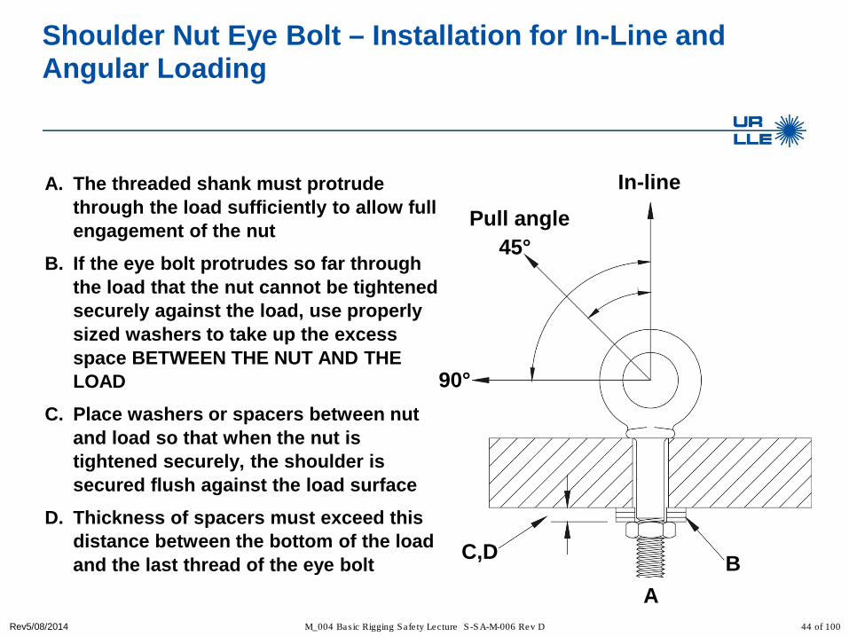
Shoulder Nut Eye Bolt – Installation for In-Line and Angular Loading
A. The threaded shank must protrude through the load sufficiently to allow full engagement of the nut
B. If the eye bolt protrudes so far through the load that the nut cannot be tightened securely against the load, use properly sized washers to take up the excess space BETWEEN THE NUT AND THE LOAD
C. Place washers or spacers between nut and load so that when the nut is tightened securely, the shoulder is secured flush against the load surface
D. Thickness of spacers must exceed this distance between the bottom of the load and the last thread of the eye bolt B C,D
45°
90°
A
In-line
44 of 100
Pull angle
Rev5/08/2014 M_004 Bas ic Rigging Safe ty Lecture S -SA-M-006 Rev D
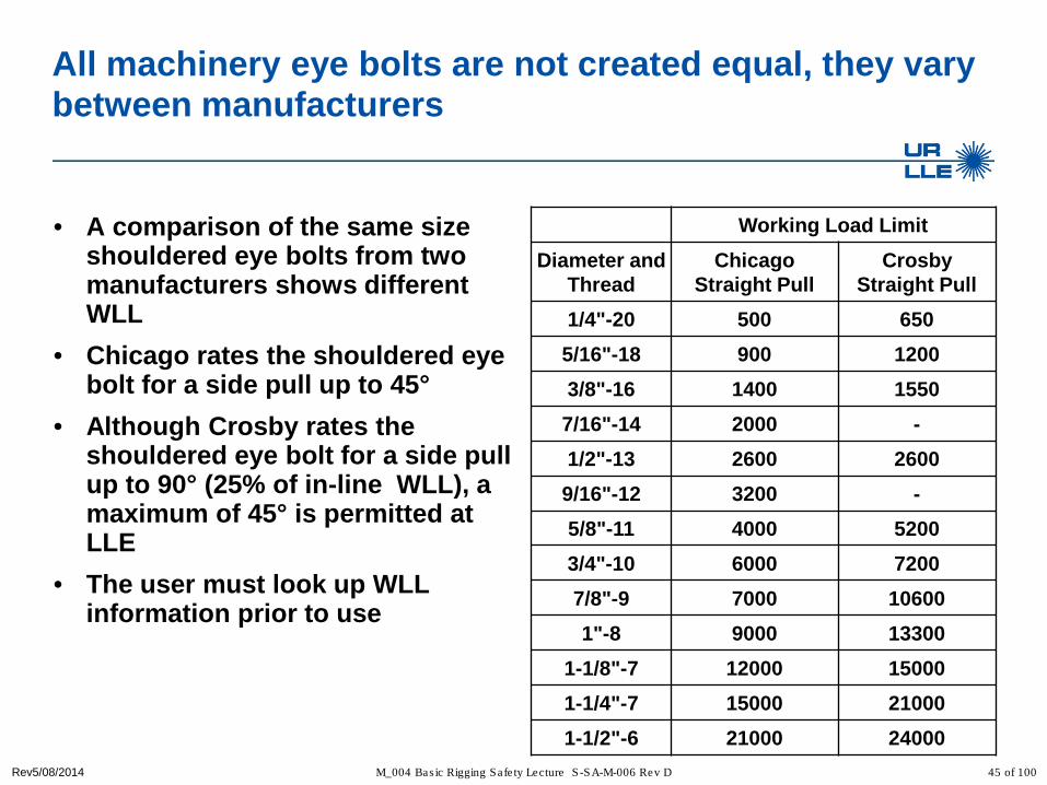
All machinery eye bolts are not created equal, they vary between manufacturers
• A comparison of the same size shouldered eye bolts from two manufacturers shows different WLL
• Chicago rates the shouldered eye bolt for a side pull up to 45°
• Although Crosby rates the shouldered eye bolt for a side pull up to 90° (25% of in-line WLL), a maximum of 45° is permitted at LLE
• The user must look up WLL information prior to use
Working Load Limit Diameter and
Thread Chicago
Straight Pull Crosby
Straight Pull 1/4"-20 500 650
5/16"-18 900 1200
3/8"-16 1400 1550
7/16"-14 2000 - 1/2"-13 2600 2600
9/16"-12 3200 - 5/8"-11 4000 5200
3/4"-10 6000 7200
7/8"-9 7000 10600
1"-8 9000 13300
1-1/8"-7 12000 15000
1-1/4"-7 15000 21000
1-1/2"-6 21000 24000 45 of 100

• One eye bolt diameter of threads or less, use two (2) nuts
• Tighten hex nut securely against load
Regular Nut & Shoulder Nut Eye Bolt - Installation for In-line Loading with a tapped through hole
• More than one eye bolt diameter of threads, only (1) nut is required
• Tighten hex nut securely against load
Rev5/08/2014 M_004 Basic Rigging Safety Lecture S-SA-M-006 Rev D 46 of 100

• One eye bolt diameter of threads or less is not allowed
Regular Nut & Shoulder Nut Eye Bolt - Installation for In-line Loading with a tapped through hole
• Engagement depth 1.5 x Diameter in steel
• Engagement depth 2.5 x Diameter in aluminum (6000 series)
Rev5/08/2014 M_004 Basic Rigging Safety Lecture S-SA-M-006 Rev D 47 of 100

Rev5/08/2014 M_004 Bas ic Rigging Safe ty Lecture S -SA-M-006 Rev D
Examples of non-load rated eyebolts that should never be used for rigging
welded eye bolt open eye bolt bent eye bolt
48 of 100

Rev5/08/2014 M_004 Bas ic Rigging Safe ty Lecture S -SA-M-006 Rev D
Machinery eye bolt Do’s
• Visually inspect eyebolts for any damage or corrosion on threads and body
• Always be sure threads on the shank and receiving holes are clean • Insure the eyebolt has proper identification markings • Always countersink receiving hole or use washers to seat the shoulder
properly • Always screw the eye bolt down completely for proper seating • Always tighten nuts securely against the load • When using blind tapped holes, make sure thread engagement is more
than 1.5 times the diameter of the thread in steel and 2.5 times in aluminum
49 of 100

Rev5/08/2014 M_004 Bas ic Rigging Safe ty Lecture S -SA-M-006 Rev D
Machinery eye bolt Don’ts
• Do not use the eyebolt if it is bent, damaged, or has been modified • Do not use if the eyebolt if it does not have proper identification
markings • Do not use shouldered eyebolts at angles between 45 and 90 degrees to
bolt axis • Do not repair, replace, or modify an eyebolt • Do not use if a gap exists between the part and eyebolt • Do not use a hook larger than the diameter of the eyebolt opening • Do not use a plain pattern eye bolt for angular pulls • Shock loading must be avoided • Never machine, grind, or cut an eye bolt • Never use eye bolt that shows signs of wear or damage • Never use eye bolt if eye or shank is bent or elongated • Never exceed the load rating
50 of 100

Rev5/08/2014 M_004 Bas ic Rigging Safe ty Lecture S -SA-M-006 Rev D
Is this eyebolt safe to use? No, because the shoulder has been damaged
51 of 100
Rev5/08/2014 M_004 Bas ic Rigging Safe ty Lecture S -SA-M-006 Rev D
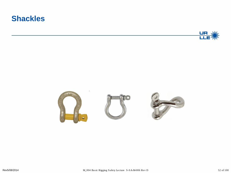
Shackles
52 of 100
Rev5/08/2014 M_004 Bas ic Rigging Safe ty Lecture S -SA-M-006 Rev D
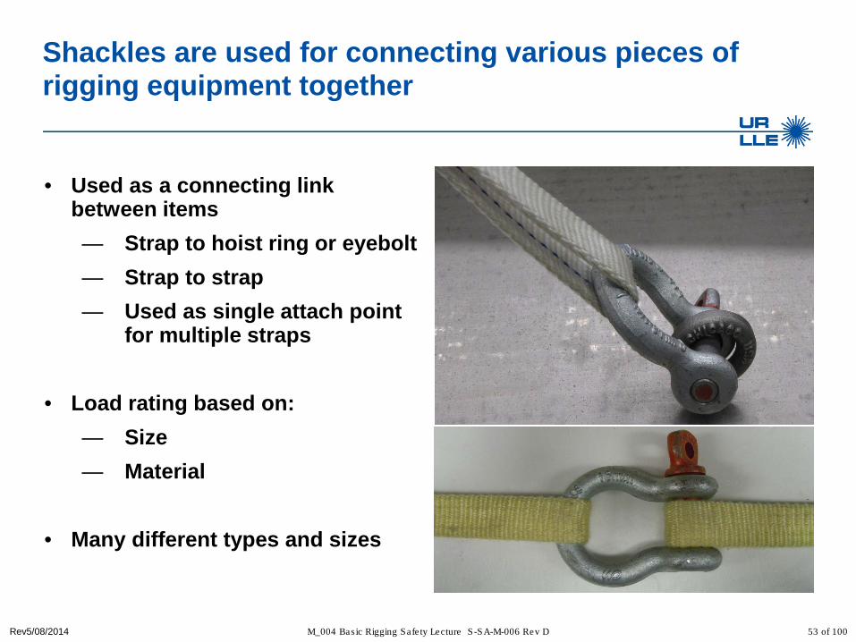
Shackles are used for connecting various pieces of rigging equipment together
• Used as a connecting link between items — Strap to hoist ring or eyebolt — Strap to strap — Used as single attach point
for multiple straps
• Load rating based on: — Size — Material
• Many different types and sizes
53 of 100

Rev5/08/2014 M_004 Bas ic Rigging Safe ty Lecture S -SA-M-006 Rev D
Examples of shackle usage
• Strap to diagnostic
• With multiple straps
54 of 100

Rev5/08/2014 M_004 Bas ic Rigging Safe ty Lecture S -SA-M-006 Rev D
Round pin shackle
• Round Pin Shackles can be used in tie down, towing, suspension or lifting applications where the load is strictly applied in-line
• Round pin shackles should never be used in rigging applications to gather multiple sling legs, or where side loading conditions may occur
Round pin shackles are not approved for use at LLE 55 of 100

Rev5/08/2014 M_004 Bas ic Rigging Safe ty Lecture S -SA-M-006 Rev D
Screw pin shackle
• Screw Pin Shackles are used in Pick and Place applications.
• For permanent or long-term installations, Crosby recommends the use of bolt type shackles. Alternatively, the screw pin shall be secured from rotation or loosening.
• Screw pin shackles can be used for applications involving side-loading circumstances
• Reduced working load limits are required for side-loading applications
• While in service, do not allow the screw pin to be rotated by a live line, such as a choker application
56 of 100
Screw pin shackles are preferred for use at LLE

Rev5/08/2014 M_004 Bas ic Rigging Safe ty Lecture S -SA-M-006 Rev D
Bolt-type shackle
• Bolt-Type Shackles can be used in any application where round pin or screw pin shackles are used
• In addition, they are recommended for permanent or long term installations and where the load may slide on the shackle pin causing the pin to rotate
• The bolt-type shackle’s secondary securement system, utilizing a nut and cotter, eliminates the requirement to tighten pin before each lift or movement of load
57 of 100
Bolt-type shackles must have the cotter pin installed

Rev5/08/2014 M_004 Bas ic Rigging Safe ty Lecture S -SA-M-006 Rev D
Shackle identification markings
Working Load Limit ( 4 ¾ T)
Manufacturer (Crosby)
Size (3/4)
45° mark
58 of 100

Rev5/08/2014 M_004 Bas ic Rigging Safe ty Lecture S -SA-M-006 Rev D
Side loading of screw pin and bolt type shackles results in a reduction of the working load limit
90°
45° In-line Angle of Side Load from
Vertical In-Line of shackle Adjusted WLL0° In-Line 100% of Rated WLL
45° from In-Line 70% of Rated WLL90° from In-Line 50% of Rated WLL
At LLE shackles are only permitted to be loaded in-line 59 of 100
90° from in-line In-line load

Rev5/08/2014 M_004 Bas ic Rigging Safe ty Lecture S -SA-M-006 Rev D
Shackle load ratings are based upon the use angle with multiple straps
• Shackles symmetrically loaded with two leg slings having a maximum included angle of 120° and can be utilized to full working load limit of the shackle
• Never exceed a 120° included angle and only use bolt-type or screw-pin shackles
120°
60 of 100

Rev5/08/2014 M_004 Bas ic Rigging Safe ty Lecture S -SA-M-006 Rev D
Shackle rigging practices for Crosby shackles
• Point loading of shackle bows is acceptable
• Point loading of shackle pins is acceptable when the load is reasonably centered on the pin
61 of 100

Rev5/08/2014 M_004 Bas ic Rigging Safe ty Lecture S -SA-M-006 Rev D
Shackle rigging practices with synthetic slings
• Folding, bunching, or pinching of synthetic slings can occur when used with shackles
• Folding, bunching, and pinching of synthetic slings reduces the sling load rating and must be avoided
62 of 100

Rev5/08/2014 M_004 Bas ic Rigging Safe ty Lecture S -SA-M-006 Rev D
Shackle rigging practices
• Screw pins shall be fully engaged • If designed for a cotter pin, it shall
be used and maintained • Applied load should be centered
in the bow to prevent side loading • Multiple sling legs must not be
applied to the pin • If the shackle is side loaded, the
rated load shall be reduced • Never have the pin against the live
line in a choker. The pin must go through the bow of the sling.
63 of 100

Rev5/08/2014 M_004 Bas ic Rigging Safe ty Lecture S -SA-M-006 Rev D
Shackle Do’s
• Visually inspect shackles for any damage or wear on ring and pin • Insure shackles have proper identification markings • Finger tighten the pin into ring of shackle • Check for proper fit of the pin into ring • Check the load ratings and use according to manufacturer
recommendations
64 of 100

Rev5/08/2014 M_004 Bas ic Rigging Safe ty Lecture S -SA-M-006 Rev D
Shackle Don’ts
• Do not use a shackle if it is bent, damaged, or has been modified • Do not use if the shackle does not have proper identification markings • Do not use a tool to tighten a shackle pin • Do not repair, replace, or modify a shackle • Do not use a shackle if the pin has been replaced with a bolt • Do not use a hook larger than the diameter of the shackle opening • Never exceed the load rating
65 of 100

Rev5/08/2014 M_004 Bas ic Rigging Safe ty Lecture S -SA-M-006 Rev D
What is the WLL of this shackle? Zero, because the screw pin has been replaced with a bolt
66 of 100
Rev5/08/2014 M_004 Bas ic Rigging Safe ty Lecture S -SA-M-006 Rev D
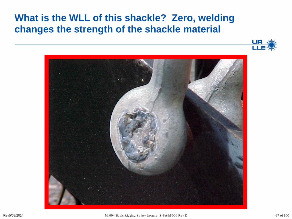
What is the WLL of this shackle? Zero, welding changes the strength of the shackle material
67 of 100

Rev5/08/2014 M_004 Bas ic Rigging Safe ty Lecture S -SA-M-006 Rev D
• Rigging hardware must be identifiable with all information clearly legible
Never use counterfeit or unknown hardware
68 of 100
Rev5/08/2014 M_004 Bas ic Rigging Safe ty Lecture S -SA-M-006 Rev D
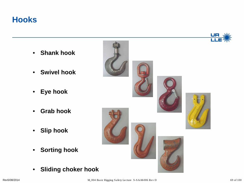
Hooks
• Shank hook
• Swivel hook
• Eye hook
• Grab hook
• Slip hook
• Sorting hook
• Sliding choker hook 69 of 100
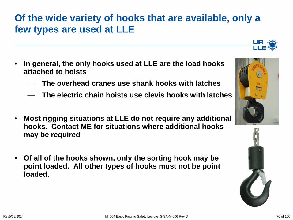
Of the wide variety of hooks that are available, only a few types are used at LLE
• In general, the only hooks used at LLE are the load hooks attached to hoists — The overhead cranes use shank hooks with latches — The electric chain hoists use clevis hooks with latches
• Most rigging situations at LLE do not require any additional
hooks. Contact ME for situations where additional hooks may be required
• Of all of the hooks shown, only the sorting hook may be point loaded. All other types of hooks must not be point loaded.
Rev5/08/2014 M_004 Basic Rigging Safety Lecture S-SA-M-006 Rev D 70 of 100

Rev5/08/2014 M_004 Bas ic Rigging Safe ty Lecture S -SA-M-006 Rev D
The load hook
• Always inspect the hook and latch before use • Never use a latch that is distorted or bent • Always make sure spring will force the latch against the
tip of the hook • Insure there is no excessive wear in the saddle of the
hook • Always make sure the hook supports the load. The
latch must never support the load • Latches are intended to retain loose sling or devices
under slack conditions • Latches are not intended to be an anti-fouling device • Only load the hook in the “saddle” or “bowl” within ±45°
of vertical • Hooks are only to be loaded In-line
71 of 100

Rev5/08/2014 M_004 Bas ic Rigging Safe ty Lecture S -SA-M-006 Rev D
What is wrong with this picture?
Hook too big for eye Point loaded hook
Eye bolt not seated
72 of 100

Rev5/08/2014 M_004 Bas ic Rigging Safe ty Lecture S -SA-M-006 Rev D
Loading the load hook
• When placing two sling legs in a hook, make sure the angle between the legs is less than 90° and if the hook or load is tilted, nothing bears against the bottom of this latch
• For two legged slings with angles greater than 90°, use an intermediate link such as a master link or bolt type shackle to collect the legs of the slings. The intermediate link can be placed over the hook to provide an in-line load on the hook. This approach must also be used when using slings with three or more legs.
• Make sure all rigging materials are secured inside the latch area and the latch closes
• Never point load a hook
73 of 100

Rev5/08/2014 M_004 Bas ic Rigging Safe ty Lecture S -SA-M-006 Rev D
Hook latches must be closed
74 of 100

Rev5/08/2014 M_004 Bas ic Rigging Safe ty Lecture S -SA-M-006 Rev D
Are these hooks acceptable for use?
No! No!! and No!!!
75 of 100

Rev5/08/2014 M_004 Bas ic Rigging Safe ty Lecture S -SA-M-006 Rev D
Rigging math
θsin# •=
legsLoadonSlingTensi
θtan# •=
legsLoadrceCollapseFo
Load The sling angle θ is always measured from the horizontal
76 of 100
θ

Rev5/08/2014 M_004 Bas ic Rigging Safe ty Lecture S -SA-M-006 Rev D
Sling tension in a vertical hitch
10,000 Lbs.
10,000 Lbs. of tension on Sling
What is the sling tension?
77 of 100

Rev5/08/2014 M_004 Bas ic Rigging Safe ty Lecture S -SA-M-006 Rev D
Sling tension in a two leg vertical hitch (basket hitch)
10,000 Lbs. 10,000 Lbs. 10,000 Lbs.
What is the sling tension on each leg? 5,000 Lbs.
of tension on each Sling
5,000 Lbs. of tension on
each Sling
78 of 100

Rev5/08/2014 M_004 Bas ic Rigging Safe ty Lecture S -SA-M-006 Rev D
Sling tension in a two leg bridle hitch
Load
79 of 100
Sling tension will increase as the sling angle θ gets smaller
θ

Rev5/08/2014 M_004 Bas ic Rigging Safe ty Lecture S -SA-M-006 Rev D
60o
10,000 Lbs.
60o 60o
Sling tension in a two leg bridle hitch at 60°
5,775 lbs. 5,775 lbs.
80 of 100

Rev5/08/2014 M_004 Bas ic Rigging Safe ty Lecture S -SA-M-006 Rev D
45o
10,000 Lbs.
45o
7,070 lbs. 7,070 lbs.
45o 45o 45o 45o 45o 45o 45o
Sling tension in a two leg bridle hitch at 45°
45o 45o
81 of 100

Rev5/08/2014 M_004 Bas ic Rigging Safe ty Lecture S -SA-M-006 Rev D
30o
10,000 Lbs.
30o
10,000 lbs. 10,000 lbs.
Sling tension in a two leg bridle hitch at 30°
82 of 100
Notice that at 30° the tension in the sling is equal to the Load

Rev5/08/2014 M_004 Bas ic Rigging Safe ty Lecture S -SA-M-006 Rev D
10o
10,000 Lbs.
10o
28,800 lbs. 28,800 lbs.
Sling tension in a two leg bridle hitch at 10°
10o
83 of 100
Notice that at below 30° the tension in the sling is greater than Load

Rev5/08/2014 M_004 Bas ic Rigging Safe ty Lecture S -SA-M-006 Rev D
Using a sling at any angle other than vertical applies a collapsing force on the load
• High collapsing forces can lead to — load buckling — exceeding the pad eye strength of where the hoist attaches to the
load
Collapsing Force
84 of 100

Rev5/08/2014 M_004 Bas ic Rigging Safe ty Lecture S -SA-M-006 Rev D
Rigging with a 3 or 4 sling bridle hitches
• With 3 and 4 leg sling bridle hitches, only 2 legs will likely carry the load while the other two steady (balance) the load
• Use only 2 legs when calculating the required load rating for rigging equipment
• Use the smallest sling angle when calculating load rating
85 of 100

Rev5/08/2014 M_004 Bas ic Rigging Safe ty Lecture S -SA-M-006 Rev D
Checking sling angles with simple geometry
• For 60° sling angle — All sides of the triangle are
equal length
• For 45° sling angle — The base of the triangle is
twice the height
• For 30° sling angle — The height is one-half of the
sling length
60°
45°
30°
L
L L
2H
H
H 2H
86 of 100

Rev5/08/2014 M_004 Bas ic Rigging Safe ty Lecture S -SA-M-006 Rev D
30o
10,000 Lbs.
30o
For a two leg bridle hitch the basic rigger should size rigging hardware based on a two leg bridle hitch at 30°
• Recall – Shackles symmetrically loaded with two leg slings having a maximum included angle of 120° can be utilized to the full working load limit of the shackle
120o 10,000 lbs. 10,000 lbs.
• Select the sling load rating to be equal or greater than the payload and use a sling angle greater than 30°
87 of 100

Rev5/08/2014 M_004 Bas ic Rigging Safe ty Lecture S -SA-M-006 Rev D
Basic rigging practices
• When multiple slings are used on a common hook or bridle; — Always use sling angles greater than 30° — For sling load calculations use Sling Tension = Load
• All rigging hardware must satisfy the load rating requirements of the lift
to be performed — It either meets the load requirements or not (there is no such thing
as just over the load capacity)
• Use single slings between hooks and attachment points on the payload — do not reeve slings between attachment points
• All slings must be straight and free of knots
88 of 100

Rev5/08/2014 M_004 Bas ic Rigging Safe ty Lecture S -SA-M-006 Rev D
Basic rigging practices – continued
• When more than one wide sling (>1”) or two narrow slings (1”) are required, they shall be placed in a shackle or bridle which is then placed on the crane hook
WRONG
CORRECT
89 of 100

Rev5/08/2014 M_004 Bas ic Rigging Safe ty Lecture S -SA-M-006 Rev D
Hand signals
• Posters containing complete hand single information are posted near the overhead bridge cranes
• Complete knowledge of the hand signals is required for operation of the overhead cranes
• Complete knowledge of the hand signals is required for all riggers
90 of 100

Rev5/08/2014 M_004 Bas ic Rigging Safe ty Lecture S -SA-M-006 Rev D
Knowledge of hand signals is required
• Hand signals are not likely to be needed in most spaces because of close proximity and the use of radios
• However, all operators must know all of the listed/posted hand signals
• The hoist operator will only follow hand signals from a designated signalman (usually a rigger)
• Anyone may call for a stop or an emergency stop and it must be obeyed by the hoist operator
91 of 100

Rev5/08/2014 M_004 Bas ic Rigging Safe ty Lecture S -SA-M-006 Rev D
Knowledge of these eight hand signals is required
92 of 100

Rev5/08/2014 M_004 Bas ic Rigging Safe ty Lecture S -SA-M-006 Rev D
Qualified Advanced Riggers
• Advanced Riggers are available to support Basic Riggers to ensure safe lifting conditions — Dan Neyland, Omega XOPS — Jeff Rodas, EP XOPS — Mark Romanofsky, ME — Milt Shoup, ME
93 of 100
Rev5/08/2014 M_004 Bas ic Rigging Safe ty Lecture S -SA-M-006 Rev D
Safety is everyone’s business and compliance with safety procedures is MANDATORY
• If an activity or practice seems unsafe, “Stop Work” and take the time to address concerns
• Only designated or qualified personnel may attach loads to an overhead hoist
• No LLE personnel are qualified or permitted to repair rigging equipment
• Only approved/rated rigging gear shall be attached to a load hook • Load ratings shall never be exceeded • It is the riggers responsibility to ensure all components used in a
rigging operation meet the required load ratings — If a rigger is unable to determine a proper rigging configuration
contact ME or an Advanced Rigger for support
Summary
94 of 100

Example test questions
• A payload is being lifted with using a vertical hitch with the following components; Plain machinery eye bolt (WLL 2600 lb), synthetic sling (vertical WLL 10000 lb), Hoist (1T). What is the maximum payload? — 1300 lb — 2000 lb — 2600 lb — 10000 lb — Not enough information or not safe
• 2000 lb – limited by the hoist
Rev5/08/2014 M_004 Basic Rigging Safety Lecture S-SA-M-006 Rev D 95 of 100

Example test questions
• A payload is being lifted with a sling in basket hitch configuration with the following components; synthetic sling (basket WLL 10000 lb), and Hoist (4T). What is the maximum payload? — 4000 lb — 8000 lb — 10000 lb — Not enough information or not safe
• Not enough information – What is the sling angle?
Rev5/08/2014 M_004 Basic Rigging Safety Lecture S-SA-M-006 Rev D 96 of 100

Example test questions
• A payload is being lifted using a 2 leg bridle hitch assembled with the following individual components; Plain machinery eye bolts (WLL 2600 lb), synthetic slings (vertical WLL 1000 lb), Shackles (WLL 4T), and Hoist (5T). What is the maximum payload? — 1000 lb — 1300 lb — 2600 lb — 8000 lb — 10000 lb — Not enough information or not safe
• Not safe – Plain eye bolts can ONLY be used for vertical lifts, no sling
angle provided
Rev5/08/2014 M_004 Basic Rigging Safety Lecture S-SA-M-006 Rev D 97 of 100

Example test questions
• A payload is being lifted using a 2 leg bridle hitch assembled with the following individual components; Plain machinery eye bolts (WLL 2600 lb), synthetic slings (vertical WLL 1000 lb), Shackles (WLL 4T), and Hoist (5T). The sling angle is 30°. What is the maximum payload? — 1000 lb — 1300 lb — 2600 lb — 8000 lb — 10000 lb — Not enough information or not safe
• Not safe – Plain eye bolts can ONLY be used for vertical lifts
Rev5/08/2014 M_004 Basic Rigging Safety Lecture S-SA-M-006 Rev D 98 of 100

Example test questions
• A payload is being lifted using a 2 leg bridle hitch assembled with the following individual components; hoist rings (WLL 5000 lb), synthetic slings (vertical WLL 10000 lb), Shackles (WLL 4T), and Hoist (5T). The sling angle is 30°. What is the maximum payload? — 2500 lb — 5000 lb — 7500 lb — 8000 lb — 10000 lb — Not enough information or not safe
• Remember that in a 2 leg configuration at 30° the tension in the sling
tension is equal to the load
Rev5/08/2014 M_004 Basic Rigging Safety Lecture S-SA-M-006 Rev D 99 of 100

Example test questions
• A payload is being lifted using a 4 leg bridle hitch assembled with the following individual components; hoist rings (WLL 5000 lb), synthetic slings (vertical WLL 10000 lb), Shackles (WLL 4T), and Hoist (5T). The sling angle is 30°. What is the maximum payload? — 2500 lb — 5000 lb — 7500 lb — 8000 lb — 10000 lb — Not enough information or not safe
• Remember that with a 4 leg bridle hitch the load must be assumed to be
only on 2 legs
Rev5/08/2014 M_004 Basic Rigging Safety Lecture S-SA-M-006 Rev D 100 of 100