baseline proposal for 4-lane interleaved 100g...
TRANSCRIPT

Baseline Proposal for 4-lane Interleaved 100G FEC
Shawn Nicholl, Xilinx
Ben Jones, Xilinx
IEEE P802.3ck Interim Meeting
Salt Lake City, Utah
May 2019
1

Introduction
• This describes a possible baseline proposal for a new 4-lane interleaved 100G FEC sublayer for P802.3ck
• This new FEC sublayer could be used along with existing Clause 82 PCS and revised Clause 135 PMA to support the objectives for the 100GBASE-KR1 and 100GBASE-CR1 channels
• The intent of the presentation is not to propose the use of interleaved FEC for 100GBASE-KR1 and 100GBASE-CR1 channels
2

Supporters
• Pete Anslow
• Eric Baden
• Thananya Baldwin
• Paul Brooks
• Matt Brown
• Frank Chang
• Ali Ghiasi
• Mark Gustlin
• Greg LeCheminant
• David Malicoat
• Arthur Marris
• Edward Nakamoto
• Gary Nicholl
• Mark Nowell
• David Ofelt
• Jerry Pepper
• Rick Rabinovich
• Alon Regev
• Steve Sekel
• Kapil Shrikhande
• Jeff Slavick
• Rob Stone
• Pirooz Tooyserkani
• Geoff Zhang
3
“If P802.3ck determines that a new FEC is required, then I support this FEC proposal“

Previous Work
• gustlin_3ck_01_0518.pdf, proposes re-use of the 802.3bs and 802.3cd PCS/FEC/PMA sublayers in this project
• anslow_3ck_adhoc_01_072518.pdf, initial FEC performance analysis
• gustlin_3ck_01_0718.pdf, proposes a possible RS symbol muxing scheme in the PMA sublayer, this is no longer being considered
• anslow_3ck_01_0918.pdf, updated FEC performance analysis
• gustlin_3ck_01_1118.pdf, proposes a new interleaved FEC sublayer for the most difficult channels at 100GbE
• anslow_3ck_01_1118.pdf, analyses the interleaved FEC performance
• nicholl_3cn_01b_181211.pdf, proposes a baseline for CGMII extender (not adopted)
4

Previous Work
• gustlin_3ck_01_0119.pdf, proposes a baseline for the new interleaved FEC sublayer
• nicholl_3ct_01a_0319.pdf, contains adopted 802.3ct baseline for Inverse RS-FEC
• gustlin_3ck_01_0319.pdf, contains adopted 802.3ck baseline for PCS/FEC/PMA for 200 Gb/s and 400 Gb/s interfaces as well as baseline for PCS/FEC/PMA for C2M and C2C-S 100 Gb/s interfaces
• nicholl_3ck_adhoc_01b_042419.pdf, contains details of 4-lane Interleaved 100G FEC
5

Overview
• This presentation works through details associated with a proposed 4-lane interleaved 100G FEC for P802.3ck
• Use of 4 FEC lanes differs from previous 2-lane interleaved FEC proposal
• During offline consensus building, folks expressed a stronger appetite for 4 lanes
• Greater commonality with CL91
• Alignment marker method same as 802.3cd-2018 CL91
• Consistent with the capacity/lanes ratio already found in FEC (CL91), PCS (CL119)
• 100G: 4 FEC lanes 25Gbps / lane
• 200G: 8 PCS lanes 25Gbps / lane
• 400G: 16 PCS lanes 25Gbps / lane
• Possibly allows for reduced development effort due to re-use from existing implementations
• Allows system integrators to use 25G-based devices (eg. FPGA’s) to support new interleaved FEC with external bit muxes/gearboxes
• Expect FLR performance similar to 400G with 100G serial lanes (CL119 PCS)
• The resultant 4-lane interleaved FEC heavily leverages existing CL91 and CL119
6

802.3cd Architecture – 100GbE
• Architecture and possible implementations are shown below for 100GbE
• FEC is in the FEC sublayer, RS(544,514) aka “KP4” FEC
• An AUI may exist between the PCS and FEC sublayers
7
MDI
Medium
MAC/RS
PMD
PMA
PCS
100GAUI-x
PMA
MAC Device (MAC/PCS/FEC/PMA)
Module
MDI
Medium
Chip to Module I/F
100GAUI-2
IEEE ArchPossible
Implementation
MAC Device (MAC/PCS/FEC/PMA)
Module
MDI
Medium
Possible
Implementation
Retimer/Mux
Chip to Chip I/F
100GAUI-2
Chip to Module I/F
100GAUI-2
FEC

Proposed Interleaved 100G FEC Sublayer Architecture
8
100GBASE-R PCS
Clause 91 FEC
PMA
PMD
MEDIUM
MDI
100G MAC/RS
100GMII
100GBASE-R PCS
New Interleaved FEC
PMA
PMD
MEDIUM
MDI
100G MAC/RS
100GMII
100GBASE-DRC2M/C2C I/F
100GBASE-KR1
100GBASE-CR1

New Interleaved 100G FEC Sublayer
2x50G RS(544,514) FEC
interleaving
9
Message
RS Encoder
Codeword
Symbol Distribution
PMA
(bit Muxing)
Message A
RS Encoder A
Codeword A
Interleaving & Distribution (symbol based)
10b Distribution
Message B
RS Encoder B
Codeword B
A portion of today’s Clause 91 FEC
A portion of a possible new FEC sublayer
Assuming ABABBABA ordering
4 FEC lanes
PMA
(bit Muxing)
4 FEC lanes
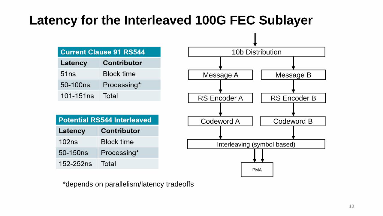
Latency for the Interleaved 100G FEC Sublayer
10
Message A
RS Encoder A
Codeword A
Interleaving (symbol based)
10b Distribution
Message B
RS Encoder B
Codeword B
*depends on parallelism/latency tradeoffs
PMA

PMA for New Interleaved 100GbE FEC Sublayer
11
• PMA provide simple bit mux options
• 1:1 pass through (4x26.5625 Gbps)
• 2:1 bit mux down to two lanes (2x53.125 Gbps)
• 4:1 bit mux down to a single lane (1x106.25 Gbps)
• Re-use of Clause 135
PMA
(pass through)
4 FEC lanes
PMA
(bit Muxing)
4 FEC lanes
PMA
(bit Muxing)
4 FEC lanes
4 PMA lanes 2 PMA lanes 1 PMA lane

100GbE Example Use Cases – Optical (CL91 FEC)
12
Seamless Clause 91 FEC end to end, backwards compatible
NewModule
Legacy Module
100GBASE-DRor 100G MSA Legacy
Host Device
CL
91
FE
C
50G/lane AUI
100GAUI-2C2M
New Host Device
CL
91
FE
C
100G/lane AUI
100GAUI-1C2M
Retimer to 100GAUI-1, backwards compatible
NewModule
Legacy Module
100GBASE-DRor 100G MSA Legacy
Host Device
CL
91
FE
C
50G/lane AUI
100GAUI-2C2M
New Host Device
CL
91
FE
C
100G/lane AUIRetimer/Mux
100GAUI-1C2M
100GAUI-1C2C
Retimer/mux to 100G AUI-1, backwards compatible
NewModule
Legacy Module
100GBASE-DRor 100G MSA Legacy
Host Device
CL
91
FE
C
50G/lane AUI
100GAUI-2C2M
New Host Device
CL
91
FE
C
50G/lane AUIRetimer/Mux
100GAUI-1C2M
100GAUI-2C2C

100GbE Example Use Cases – Copper (1 of 2 slides)
13
New Host Device
Retimer/Mux
Int
FEC
50G/lane AUI
Simple bit mux between 2x53.125 to 1x106.25
Copper CopperNew Host
DeviceInt
FEC
100G/lane
100GBASE-CR1
New Host Device
Copper CopperNew Host
DeviceInt
FEC
Int
FEC
100G/lane 100G/lane
New Interleaved FEC end to end
100GBASE-CR1
New Host Device
Retimer/Mux
Int
FEC
25G/lane AUI
Simple bit mux between 4x26.5625 to 1x106.25
Copper CopperNew Host
DeviceInt
FEC
100G/lane
100GBASE-CR1
100GAUI-4C2C
100GAUI-2C2C
MDI
MDI
MDI
MDI
MDI
MDI

100GbE Example Use Cases – Copper (2 of 2 slides)
14
New Host Device
Retimer
Int
FEC
100G/lane AUI
Retimer in the path for CR
Copper CopperNew Host
DeviceInt
FEC
100G/lane
100GBASE-CR1
100GAUI-1C2C-S
MDI MDI

100GbE Example Use Cases – With Inverse RS-FEC
15
New Host Device
NewModule100GAUI-1
C2C-L
RetimerConverter
Legacy Module
LegacyHost
DeviceInt
FEC
CL
91
FE
C
100GAUI-1C2M
100G/lane AUI 50G/lane AUI
100GAUI-2C2M
“Retimer” converts from Interleaved FEC to Clause 91 FEC
InverseRS-FEC
FEC Domain A
FEC Domain B
• An Inverse RS-FEC sublayer (proposed in 802.3ct) can be used for these scenarios
New Host Device
Copper CopperLegacy
Host DeviceIn
tFE
C
100G/lane 50G/lane AUI
“Retimer” converts from Interleaved FEC to Clause 91 FEC
100GBASE-CR1
RetimerConverter
100GAUI-2C2C
InverseRS-FEC
CL
91
FE
C
FEC Domain A
FEC Domain B
Int
CL9
1
Int
CL9
1
100GBASE-DRor 100G MSA
• Note: Above is akin to PAM4-based host talking to CAUI-4 QSFP28 module through KP/KR FEC converter chip
MDI MDI

Interleaved 100G FEC Tx Stack Comparison (Proposed)
16
FEC Encode
Symbol Distribution
Encode
Scramble
Alignment Insertion
Block Distribution
Lane Block Sync
Alignment Lock
Lane Reorder
Alignment Removal
256B/257B Transcode
Pre FEC Distribution
FEC Encode (A & B)
Interleave
PCS
FEC
Co
llap
ses
for
collo
cate
d s
ub
laye
rs
Encode
Scramble
Alignment Insertion
Block Distribution
Lane Block Sync
Alignment Lock
Lane Reorder
Alignment Removal
256B/257B Transcode
PCS
FEC
Symbol Distribution
Exis
tin
g C
L91
TX
Sta
ck
CL8
2 +
New
10
0G
bE
FEC
TX
Sta
ck
Leve
rage
sC
L11
9 T
X S
tack
Exis
tin
g C
L82
TX
Sta
ck
Exis
tin
g C
L82
TX
Sta
ckEx
isti
ng
CL9
1 T
X S
tack
Alignment InsertionAlignment Insertion Map Map
Leve
rage
sC
L91
, CL1
19
TX S
tack

Interleaved 100G FEC Rx Stack Comparison (Proposed)
FEC Decode
Lane Reorder
Post FEC Interleave
FEC Decode (A & B)
De-Interleave
PCS
FEC
Co
llap
ses
for
collo
cate
d s
ub
laye
rs
Decode
Descramble
Lane Reorder
Alignment Removal
Alignment Insert
Block Distribution
256B/257B Transcode
PCS
FEC
Lane Reorder
Alignment lock Lane deskew
Lane block sync
Decode
Descramble
Lane Reorder
Alignment Removal
Alignment lock Lane deskew
Lane block sync
Alignment Insert
Block Distribution
256B/257B Transcode
17Alignment Lock and Deskew Alignment Lock and Deskew
Exis
tin
g C
L82
RX
Sta
ckEx
isti
ng
CL9
1 R
X S
tack
Leve
rage
sC
L11
9 R
X S
tack
Exis
tin
g C
L82
RX
Sta
ck
CL8
2 +
New
10
0G
bE
FEC
RX
Sta
ck
Exis
tin
g C
L91
RX
Sta
ck
Leve
rage
sC
L91
, CL1
19
RX
Sta
ck
Alignment Removal Map Alignment Removal Map

Current 802.3-2018 Clause 91
18
• This is the existing Clause 91 RS-FEC

Current 802.3-2018 CL91, CL119 Tx RS-FEC(s)
19

Current 802.3-2018 CL91, CL119 Rx RS-FEC(s)
20
NoDiagramIn CL119
For Receive Bit Ordering
21
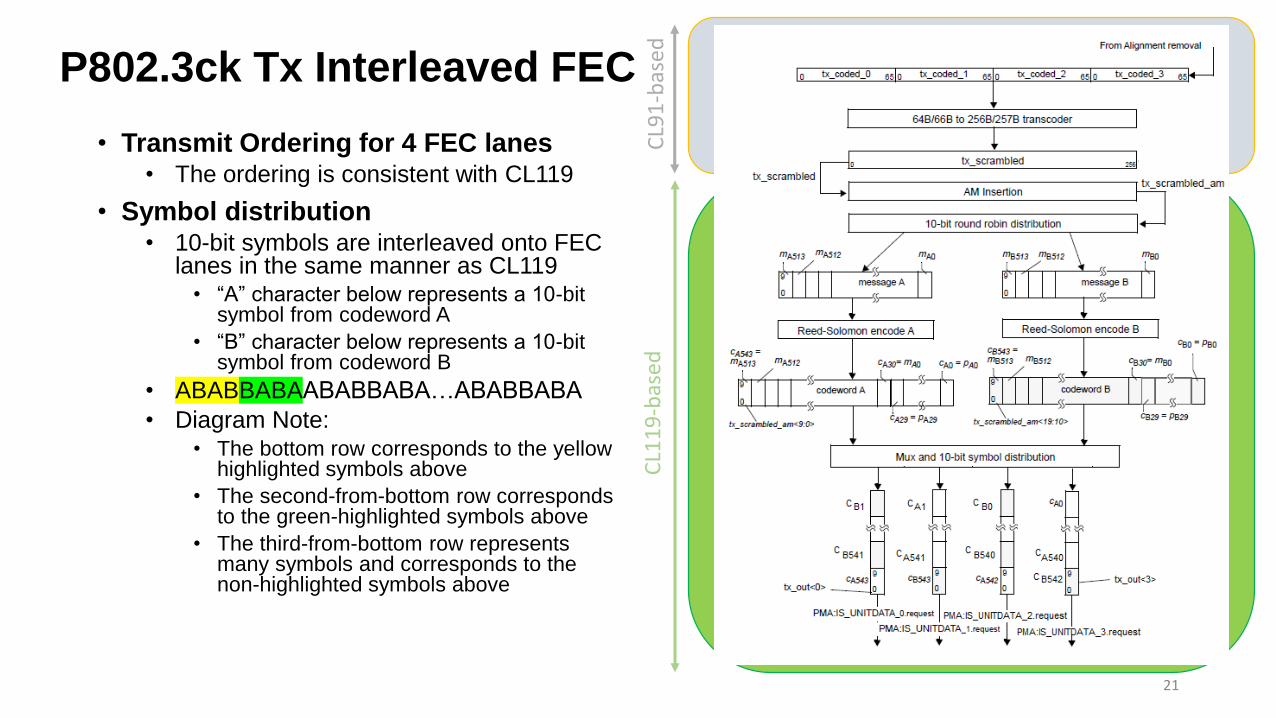
• Transmit Ordering for 4 FEC lanes• The ordering is consistent with CL119
• Symbol distribution• 10-bit symbols are interleaved onto FEC
lanes in the same manner as CL119• “A” character below represents a 10-bit
symbol from codeword A
• “B” character below represents a 10-bit symbol from codeword B
• ABABBABAABABBABA…ABABBABA
• Diagram Note:• The bottom row corresponds to the yellow
highlighted symbols above
• The second-from-bottom row corresponds to the green-highlighted symbols above
• The third-from-bottom row represents many symbols and corresponds to the non-highlighted symbols above
CL1
19
-bas
edC
L91
-bas
edP802.3ck Tx Interleaved FEC

P802.3ck Rx Interleaved FEC
• Receive Ordering for 4 FEC lanes• The ordering is consistent with CL119
• Symbol distribution• 10-bit symbols are de-interleaved from
FEC lanes in the same manner as CL119• “A” character below represents a 10-bit
symbol from codeword A
• “B” character below represents a 10-bit symbol from codeword B
• ABABBABAABABBABA…ABABBABA
• Diagram Note:• The row below “Alignment lock, deskew,
and lane reorder” block corresponds to the yellow highlighted symbols above
• The second-row below “Alignment lock, deskew, and lane reorder” corresponds to the green-highlighted symbols above
• The third-row below represents many symbols and corresponds to the non-highlighted symbols above
CL1
19
-bas
edC
L91
-bas
ed22

Performance Considerations
• The 4:1 bit mux results in slightly degraded performance compared to the 2:1 bit mux
• See anslow_3ck_01_1118.pdf slide 9
• 400G with 4:1 bit mux is shown by the green curve
• Already adopted as P802.3ck baseline in gustlin_3ck_01_0319.pdf
• 100G with 2:1 bit mux is shown by the red curve
• It is expected that the performance of 100G with 4:1 bit mux would be no worse than 400G with 4:1 bit mux
• In other words, regardless of the limits we put on the DFE, we will get the performance of 400G
23

Summary
• This presentation works through the ingredients of a 4-lane interleaved 100G FEC
• Slides that follow contain technical details of the proposed FEC
• Draft text is proposed for a new Clause 300
24

Technical Details Beyond Here!
25

P802.3ck – Interleaved FEC Tx – CL91-based functions
• Assume new Clause 300 for Interleaved FEC
• 300.5.2 Transmit function
• Sections that could be directly used from Clause 91 are following:
• 300.5.2.1 Lane block synchronization
• Same as 91.5.2.1 Lane block synchronization
• 300.5.2.2 Alignment lock and deskew
• Same as 91.5.2.2 Alignment lock and deskew
• 300.5.2.3 Lane reorder
• Same as 91.5.2.3 Lane reorder
• 300.5.2.4 Alignment marker removal
• Same as 91.5.2.4 Alignment marker removal
• 300.5.2.5 64B/66B to 256B/257B transcoder
• Same as 91.5.2.5 64B/66B to 256B/257B transcoder
26

P802.3ck – Interleaved FEC Tx – Changes from CL91
• Sections that would be different from Clause 91 are following:
• 300.5.2.6 Alignment marker mapping and insertion
• Based on 91.5.2.6 Alignment marker mapping and insertion (as amended by 802.3cd-2018)
• amp_tx_x creation the same as CL91 with four_lane_pmd = false [no EEE deep sleep support]
• amp_tx_0=am0, amp_tx_1=am0, amp_tx_2=am0, amp_tx_3=am0, other AM’s are unchanged
• Remainder of mapping process to form 10280-bit block based on 119.2.4.4 “Alignment marker mapping and insertion” to account for checkboard patterning
• 300.5.2.7 Pre-FEC distribution
• Same as 119.2.4.5 Pre-FEC distribution
• 300.5.2.8 Reed-Solomon encoder
• Same as 119.2.4.6 Reed-Solomon encoder
• 300.5.2.9 Symbol distribution
• Based on 119.2.4.7 Symbol distribution
• Distribute to four FEC lanes instead of 16 (or 8)
27

Interleaved FEC Tx – Lane block synchronization
• Identical to 91.5.2.1
28
300.5.2.1 Lane block synchronization
<Contents of this section pulled directly from 91.5.2.1 Lane block synchronization>
Identicalto
802.3cdCL91
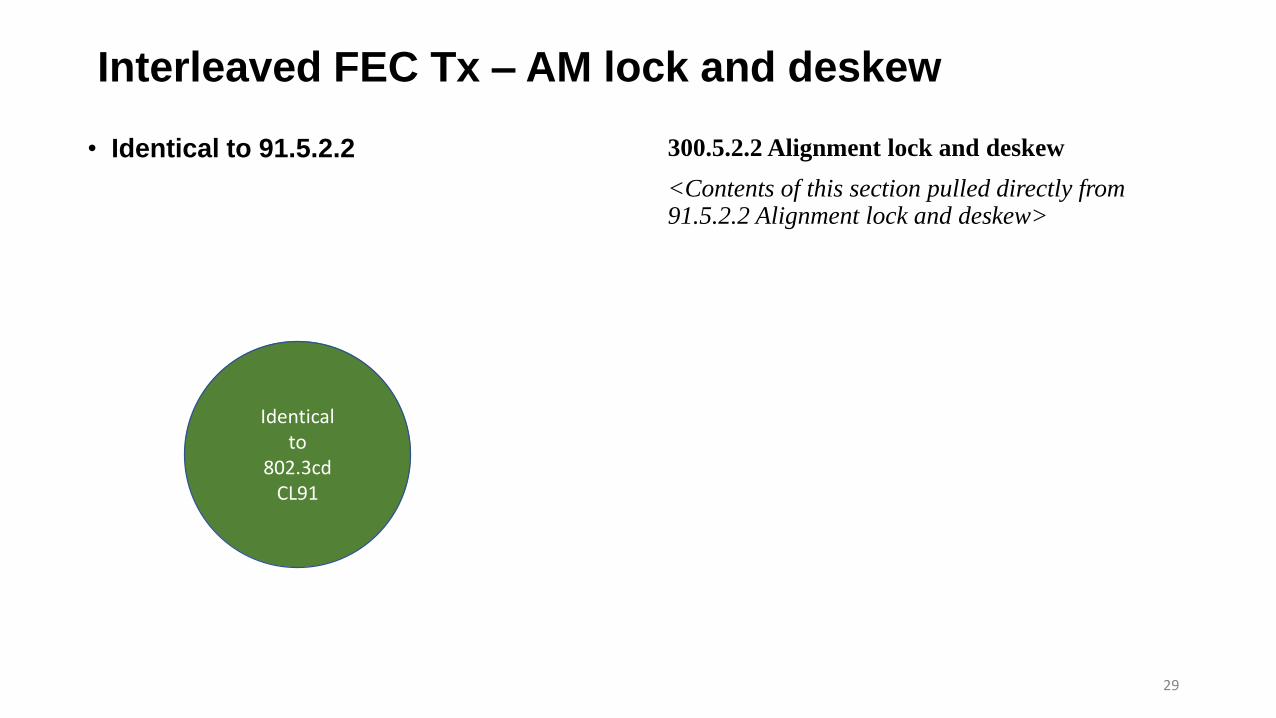
Interleaved FEC Tx – AM lock and deskew
• Identical to 91.5.2.2
29
300.5.2.2 Alignment lock and deskew
<Contents of this section pulled directly from 91.5.2.2 Alignment lock and deskew>
Identicalto
802.3cdCL91

Interleaved FEC Tx – Lane reorder
• Identical to 91.5.2.3
30
300.5.2.3 Lane reorder
<Contents of this section pulled directly from 91.5.2.3 Lane reorder>
Identicalto
802.3cdCL91

Interleaved FEC Tx – AM removal
• Identical to 91.5.2.4
31
300.5.2.4 Alignment marker removal
<Contents of this section pulled directly from 91.5.2.4 Alignment marker removal>
Identicalto
802.3cdCL91

Interleaved FEC Tx – 256B/257B Transcoder
• Identical to 91.5.2.5
32
300.5.2.5 64B/66B to 256B/257B transcoder
<Contents of this section pulled directly from 91.5.2.5 64B/66B to 256B/257B transcoder>
Identicalto
802.3cdCL91

Interleaved FEC Tx – AM Values
• Use 802.3cd-2018 CL91• AM’s for 0 to 3 are identical• Other are unique
• i.e. 16 to 19 not made identical
• 5-bit pad• Alternating between 00101 and
11010 as per CL91
• No tx_am_sf (CL 119) field• FEC degrade signaling not
supported
33
300.5.2.6 Alignment marker mapping and insertion
For x=0 to 19, amp_tx_x<63:0> is constructed as follows:
a) Set y = 0 when x <= 3, otherwise set y = x.
b) amp_tx_x<23:0> is set to M0, M1, and M2 as shown in Figure 82-9 (bits 25 to 2) using the values in Table 82-2 for PCS lane number y.
c) amp_tx_x<31:24> = am_tx_x<33:26>
d) amp_tx_x<55:32> is set to M4, M5, and M6 as shown in Figure 82-9 (bits 57 to 34) using the values in Table 82-2 for PCS lane number y.
e) amp_tx_x<63:56> = am_tx_x<65:58>
This process replaces the fixed bytes of the alignment markers received, possibly with errors, with the values from Table 82-2. In addition it substitutes the fixed bytes of the alignment markers corresponding to PCS lanes 1, 2, and 3 with the fixed bytes for the alignment marker corresponding to PCS lane 0. The variable bytes BIP are unchanged. This process simplifies receiver synchronization since the receiver only needs to search for the fixed bytes corresponding to PCS lane 0 on each FEC lane.
HeavilyLeverages802.3cd
CL91

Interleaved FEC Tx – BIP Preservation
• Preserve the alignment marker BIP fields as they pass through the FEC sublayer
• This provides support for an architecture that includes a remote FEC engine
• The CAUI-n that is unprotected by FEC will still contain useful BIP information
34
HeavilyLeverages
Clause91
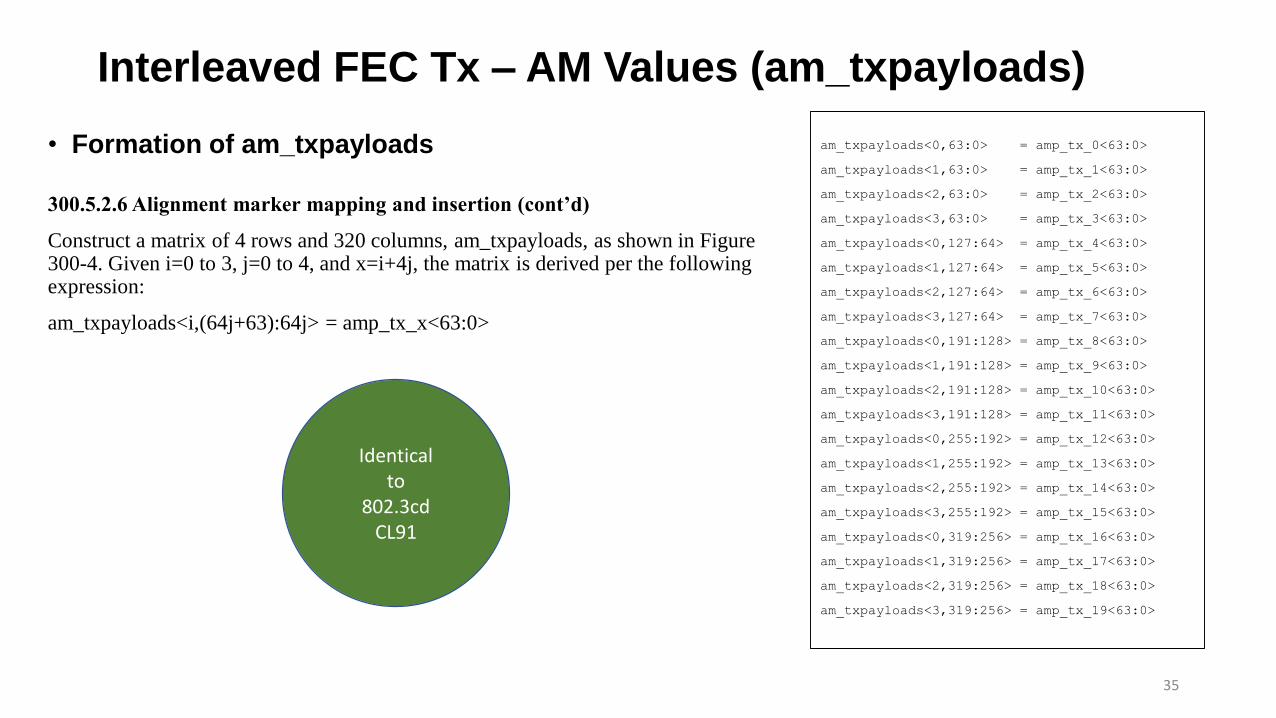
Interleaved FEC Tx – AM Values (am_txpayloads)
35
300.5.2.6 Alignment marker mapping and insertion (cont’d)
Construct a matrix of 4 rows and 320 columns, am_txpayloads, as shown in Figure 300-4. Given i=0 to 3, j=0 to 4, and x=i+4j, the matrix is derived per the following expression:
am_txpayloads<i,(64j+63):64j> = amp_tx_x<63:0>
• Formation of am_txpayloads am_txpayloads<0,63:0> = amp_tx_0<63:0>
am_txpayloads<1,63:0> = amp_tx_1<63:0>
am_txpayloads<2,63:0> = amp_tx_2<63:0>
am_txpayloads<3,63:0> = amp_tx_3<63:0>
am_txpayloads<0,127:64> = amp_tx_4<63:0>
am_txpayloads<1,127:64> = amp_tx_5<63:0>
am_txpayloads<2,127:64> = amp_tx_6<63:0>
am_txpayloads<3,127:64> = amp_tx_7<63:0>
am_txpayloads<0,191:128> = amp_tx_8<63:0>
am_txpayloads<1,191:128> = amp_tx_9<63:0>
am_txpayloads<2,191:128> = amp_tx_10<63:0>
am_txpayloads<3,191:128> = amp_tx_11<63:0>
am_txpayloads<0,255:192> = amp_tx_12<63:0>
am_txpayloads<1,255:192> = amp_tx_13<63:0>
am_txpayloads<2,255:192> = amp_tx_14<63:0>
am_txpayloads<3,255:192> = amp_tx_15<63:0>
am_txpayloads<0,319:256> = amp_tx_16<63:0>
am_txpayloads<1,319:256> = amp_tx_17<63:0>
am_txpayloads<2,319:256> = amp_tx_18<63:0>
am_txpayloads<3,319:256> = amp_tx_19<63:0>
Identicalto
802.3cdCL91
Interleaved FEC Tx – AM Values (am_txmapped)
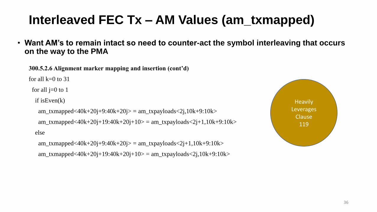
• Want AM’s to remain intact so need to counter-act the symbol interleaving that occurs on the way to the PMA
36
300.5.2.6 Alignment marker mapping and insertion (cont’d)
for all k=0 to 31
for all j=0 to 1
if isEven(k)
am_txmapped<40k+20j+9:40k+20j> = am_txpayloads<2j,10k+9:10k>
am_txmapped<40k+20j+19:40k+20j+10> = am_txpayloads<2j+1,10k+9:10k>
else
am_txmapped<40k+20j+9:40k+20j> = am_txpayloads<2j+1,10k+9:10k>
am_txmapped<40k+20j+19:40k+20j+10> = am_txpayloads<2j,10k+9:10k>
HeavilyLeverages
Clause119

Interleaved FEC Tx – AM Values (am_txmapped)
37
am_txmapped<9:0> = am_txpayloads<0,9:0>
am_txmapped<19:10> = am_txpayloads<1,9:0>
am_txmapped<29:20> = am_txpayloads<2,9:0>
am_txmapped<39:30> = am_txpayloads<3,9:0>
am_txmapped<49:40> = am_txpayloads<1,19:10>
am_txmapped<59:50> = am_txpayloads<0,19:10>
am_txmapped<69:60> = am_txpayloads<3,19:10>
am_txmapped<79:70> = am_txpayloads<2,19:10>
am_txmapped<89:80> = am_txpayloads<0,29:20>
am_txmapped<99:90> = am_txpayloads<1,29:20>
am_txmapped<109:100> = am_txpayloads<2,29:20>
am_txmapped<119:110> = am_txpayloads<3,29:20>
am_txmapped<129:120> = am_txpayloads<1,39:30>
am_txmapped<139:130> = am_txpayloads<0,39:30>
am_txmapped<149:140> = am_txpayloads<3,39:30>
am_txmapped<159:150> = am_txpayloads<2,39:30>
am_txmapped<169:160> = am_txpayloads<0,49:40>
am_txmapped<179:170> = am_txpayloads<1,49:40>
am_txmapped<189:180> = am_txpayloads<2,49:40>
am_txmapped<199:190> = am_txpayloads<3,49:40>
<SNIP>
<SNIP>
am_txmapped<1209:1300> = am_txpayloads<0,309:300>
am_txmapped<1219:1210> = am_txpayloads<1,309:300>
am_txmapped<1229:1220> = am_txpayloads<2,309:300>
am_txmapped<1239:1230> = am_txpayloads<3,309:300>
am_txmapped<1249:1240> = am_txpayloads<1,319:310>
am_txmapped<1259:1250> = am_txpayloads<0,319:310>
am_txmapped<1269:1260> = am_txpayloads<3,319:310>
am_txmapped<1279:1270> = am_txpayloads<2,319:310>
am_txmapped<1284:1280> = 5'b00101 or 5'b11010 (alternating)
Interleaved FEC Tx – AM Spacing
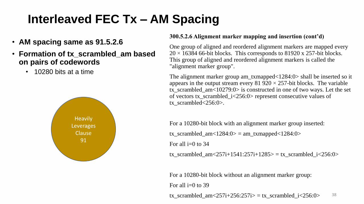
• AM spacing same as 91.5.2.6
• Formation of tx_scrambled_am based on pairs of codewords
• 10280 bits at a time
38
300.5.2.6 Alignment marker mapping and insertion (cont’d)
One group of aligned and reordered alignment markers are mapped every 20 × 16384 66-bit blocks. This corresponds to 81920 x 257-bit blocks. This group of aligned and reordered alignment markers is called the "alignment marker group".
The alignment marker group am_txmapped<1284:0> shall be inserted so it appears in the output stream every 81 920 × 257-bit blocks. The variable tx_scrambled_am<10279:0> is constructed in one of two ways. Let the set of vectors tx_scrambled_i<256:0> represent consecutive values of tx_scrambled<256:0>.
For a 10280-bit block with an alignment marker group inserted:
tx_scrambled_am<1284:0> = am_txmapped<1284:0>
For all i=0 to 34
tx_scrambled_am<257i+1541:257i+1285> = tx_scrambled_i<256:0>
For a 10280-bit block without an alignment marker group:
For all i=0 to 39
tx_scrambled_am<257i+256:257i> = tx_scrambled_i<256:0>
HeavilyLeverages
Clause91

Interleaved FEC Tx – AM Insertion
• Insertion of AM’s uses diagram similar to the one found in 119.2.4.4.1 and 119.2.4.4.2
39
------------------------------------------------ -------------------------------
| 2 codewoords | 2 codewords | | 2 codewords |
------------------------------------------------ -------------------------------
| | | | | | |
| am_mapped | tx_scrambled | tx_scrambled | * * * | am_mapped | tx_scrambled |
| 1285 bits | 35x257-bit | 40x257-bit | | 1285 bits | 35x257-bit |
| (5x257 bits) | blocks | blocks | | (5x257 bits) | blocks |
| | | | | | |
------------------------------------------------ -------------------------------
\ /
\ /
\ /
81920 x 257-bit blocks = 4096 codewords
300.5.2.6 Alignment marker mapping and insertion
For each 10280-bit block with an alignment marker group inserted, the first 257-bit block inserted after am_txmapped shall correspond to the four 66-bit blocks received on PCS lanes 0, 1, 2, and 3 that immediately followed the alignment marker on each respective lane.
Alignment marker repetition rate is shown in Figure 300-TBD.
HeavilyLeverages
Clause119
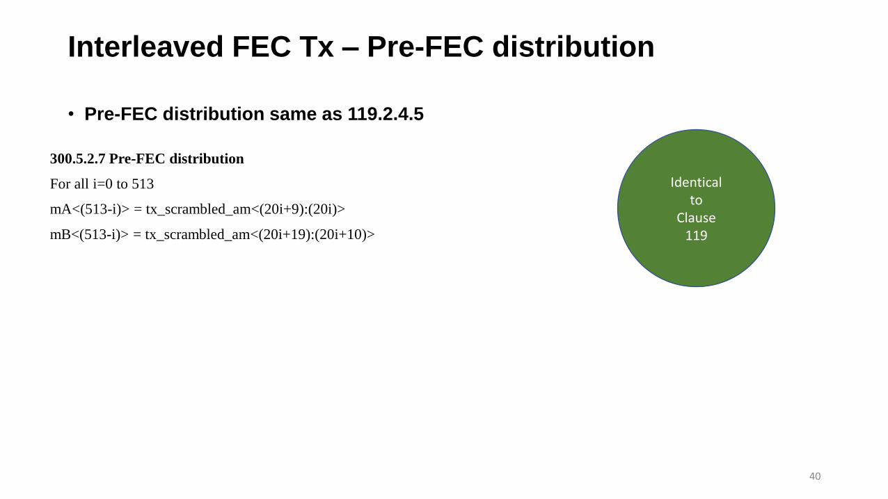
Interleaved FEC Tx – Pre-FEC distribution
• Pre-FEC distribution same as 119.2.4.5
40
300.5.2.7 Pre-FEC distribution
For all i=0 to 513
mA<(513-i)> = tx_scrambled_am<(20i+9):(20i)>
mB<(513-i)> = tx_scrambled_am<(20i+19):(20i+10)>
Identicalto
Clause119
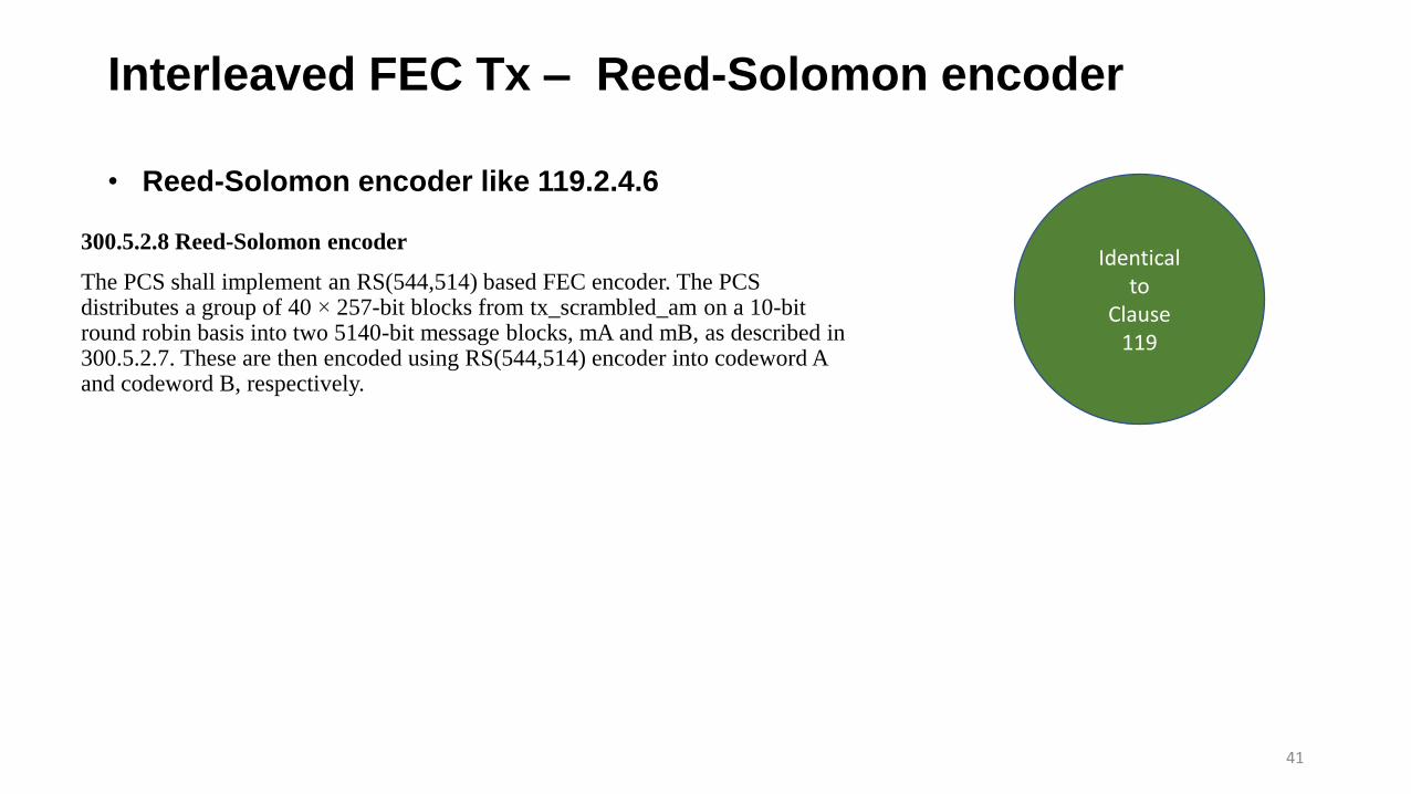
Interleaved FEC Tx – Reed-Solomon encoder
• Reed-Solomon encoder like 119.2.4.6
41
300.5.2.8 Reed-Solomon encoder
The PCS shall implement an RS(544,514) based FEC encoder. The PCS distributes a group of 40 × 257-bit blocks from tx_scrambled_am on a 10-bit round robin basis into two 5140-bit message blocks, mA and mB, as described in 300.5.2.7. These are then encoded using RS(544,514) encoder into codeword A and codeword B, respectively.
Identicalto
Clause119
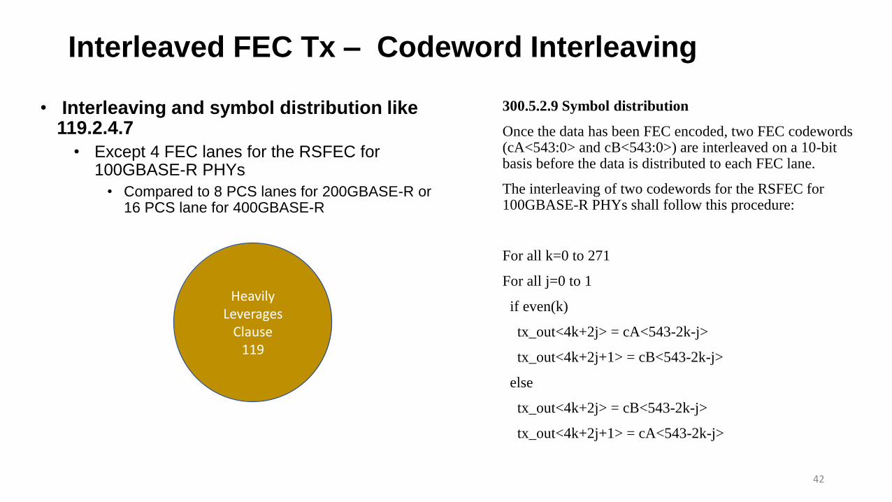
Interleaved FEC Tx – Codeword Interleaving
• Interleaving and symbol distribution like 119.2.4.7
• Except 4 FEC lanes for the RSFEC for 100GBASE-R PHYs
• Compared to 8 PCS lanes for 200GBASE-R or 16 PCS lane for 400GBASE-R
42
300.5.2.9 Symbol distribution
Once the data has been FEC encoded, two FEC codewords (cA<543:0> and cB<543:0>) are interleaved on a 10-bit basis before the data is distributed to each FEC lane.
The interleaving of two codewords for the RSFEC for 100GBASE-R PHYs shall follow this procedure:
For all k=0 to 271
For all j=0 to 1
if even(k)
tx_out<4k+2j> = cA<543-2k-j>
tx_out<4k+2j+1> = cB<543-2k-j>
else
tx_out<4k+2j> = cB<543-2k-j>
tx_out<4k+2j+1> = cA<543-2k-j>
HeavilyLeverages
Clause119

Interleaved FEC Tx – Symbol distribution
43
300.5.2.9 Symbol distribution
Once the data has been Reed-Solomon encoded and interleaved, it shall be distributed to 4 FEC lanes, one 10-bit symbol at a time, from the lowest to the highest FEC lane. The first bit transmitted from each 10-bit symbol is bit 0.
tx_out<0> = cA<543>
tx_out<1> = cB<543>
tx_out<2> = cA<542>
tx_out<3> = cB<542>
tx_out<4> = cB<541>
tx_out<5> = cA<541>
tx_out<6> = cB<540>
tx_out<7> = cA<540>
tx_out<8> = cA<539>
tx_out<9> = cB<539>
tx_out<10> = cA<538>
tx_out<11> = cB<538>
tx_out<12> = cB<537>
tx_out<13> = cA<537>
tx_out<14> = cB<536>
tx_out<15> = cA<536>
<SNIP>
<SNIP>
tx_out<1080> = cA<3>
tx_out<1081> = cB<3>
tx_out<1082> = cA<2>
tx_out<1083> = cB<2>
tx_out<1084> = cB<1>
tx_out<1085> = cA<1>
tx_out<1086> = cB<0>
tx_out<1087> = cA<0>

P802.3ck – Interleaved FEC Rx – Changes from CL91
• Assume new Clause 300 for Interleaved FEC
• 300.5.3 Receive function
• Sections that would be different from Clause 91 are following:
• 300.5.3.1 Alignment lock and deskew
• Based on 119.2.5.1 Alignment lock and deskew
• 300.5.3.2 Lane reorder and de-interleave
• Based on 119.2.5.2 Lane reorder and de-interleave
• 300.5.3.3 Reed-Solomon decoder
• Based on 119.2.5.3 Reed-Solomon decoder
• 300.5.3.4 Post FEC interleave
• Same as 119.2.5.4 Post FEC interleave
• 300.5.3.5 Alignment marker removal
• Based on 119.2.5.5 Alignment marker removal
44

P802.3ck – Interleaved FEC Rx – CL91-based functions
• Sections that could be directly used from Clause 91 are following:
• 300.5.3.6 256B/257B to 64B/66B transcoder
• Same as 91.5.3.5 256B/257B to 64B/66B transcoder
• 300.5.3.7 Block distribution
• Same as 91.5.3.6 Block distribution
• 300.5.3.8 Alignment marker mapping and insertion
• Same as 91.5.3.7 Alignment marker mapping and insertion
45
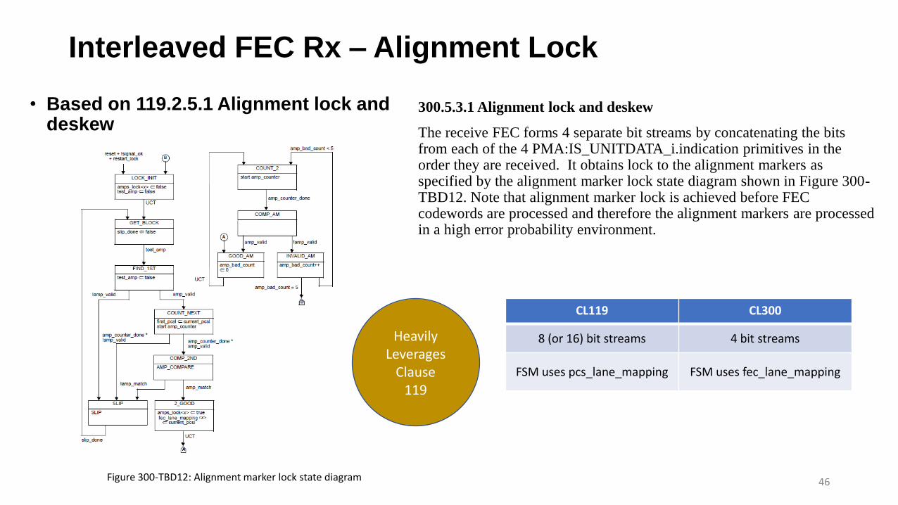
Interleaved FEC Rx – Alignment Lock
• Based on 119.2.5.1 Alignment lock and deskew
46
300.5.3.1 Alignment lock and deskew
The receive FEC forms 4 separate bit streams by concatenating the bits from each of the 4 PMA:IS_UNITDATA_i.indication primitives in the order they are received. It obtains lock to the alignment markers as specified by the alignment marker lock state diagram shown in Figure 300-TBD12. Note that alignment marker lock is achieved before FEC codewords are processed and therefore the alignment markers are processed in a high error probability environment.
HeavilyLeverages
Clause119
Figure 300-TBD12: Alignment marker lock state diagram
CL119 CL300
8 (or 16) bit streams 4 bit streams
FSM uses pcs_lane_mapping FSM uses fec_lane_mapping

Interleaved FEC Rx –Deskew
• Based on 119.2.5.1 Alignment lock and deskew
47
300.5.3.1 Alignment lock and deskew (cont’d)
After alignment marker lock is achieved on each of the 4 lanes (bit streams), all inter-lane Skew is removed as specified by the FEC synchronization state diagram shown in Figure 300-TBD13. The FEC receive function shall support a maximum Skew of 180 ns, and maximum Skew Variation of 4 ns, between FEC lanes.
Figure 300-TBD13: FEC alignment state diagram
CL119 CL300
8 or 16 lanes (bit streams) 4 lanes (bit streams)
Figure 119-13 PCS synchronization state diagram
Figure 300-TBD13 FEC alignment state diagram
FSM uses align_status FSM uses fec_align_status
FSM uses pcs_enable_deskew FSM uses fec_enable_deskew
HeavilyLeverages
Clause119

Interleaved FEC Rx – Lane reorder and de-interleave
• Based on 119.2.5.2 Lane reorder and de-interleave
• As well, pulling some text from 91.5.3.2 Lane reorder
48
300.5.3.2 Lane reorder and de-interleave
FEC lanes can be received on different lanes of the service interface from which they were originally transmitted. The FEC receive function shall order the FEC lanes according to the FEC lane number. The FEC lane number is defined by the sequence of alignment markers that are mapped to each FEC lane.
After all FEC lanes are aligned, deskewed, and reordered, the two FEC codewords are de-interleaved to reconstruct the original stream of two FEC codewords.
HeavilyLeverages
Clause119
CL119 CL300
Lane number defined by the unique portion (UM0 to UM5) of the alignment marker that is mapped to each PCS lane
lane number is defined by the sequence of alignment markers that are mapped to each FEC lane

Interleaved FEC Rx – Reed-Solomon decoder
• Based on 119.2.5.3 Reed-Solomon decoder
49
300.5.3.3 Reed-Solomon decoder
The Reed-Solomon decoder extracts the message symbols from the codeword, corrects them as necessary, and discards the parity symbols.
The Reed-Solomon decoder shall be capable of correcting any combination of up to t=15 symbol errors in a codeword. The Reed-Solomon decoder shall also be capable of indicating when an errored codeword was not corrected. The probability that the decoder fails to indicate a codeword with t+1 errors as uncorrected is not expected to exceed 10^-16. This limit is also expected to apply for t+2 errors, t+3 errors, and so on.
If bypass error indication is not supported or not enabled, when the Reed-Solomon decoder determines that a codeword contains errors that were not corrected, it shall cause the FEC receive function to set every 66-bit block within the two associated codewords to an error block (set to EBLOCK_R). This may be achieved by setting the synchronization header to 11 for all 66-bit blocks created from these codewords by the 256B/257B to 64B/66B transcoder.
HeavilyLeverages
Clause119
CL119 CL300
PCS receive function FEC receive function

Interleaved FEC Rx – Reed-Solomon decoder
• Based on 119.2.5.3 Reed-Solomon decoder
50
300.5.3.3 Reed-Solomon decoder (cont’d)
The Reed-Solomon decoder may optionally provide the ability to bypass the error indication feature to reduce the delay contributed by the FEC function. The presence of this option is indicated by the assertion of the FEC_bypass_indication_ability variable (see 300.6). When the option is provided it is enabled by the assertion of the FEC_bypass_indication_enable variable (see 300.6).
When FEC_bypass_indication_enable is asserted, additional error monitoring is performed by the Reed- Solomon decoder to reduce the likelihood that errors in a packet are not detected. The Reed-Solomon decoder counts the number of symbol errors detected on all PCS lanes in consecutive non-overlapping blocks of 8192 codewords. When the number of symbol errors in a block of 8192 codewords exceeds 5560, the Reed-Solomon decoder shall assert hi_ser for a period of 60 ms to 75 ms.
HeavilyLeverages
Clause119
CL119 CL300
Last two paragraphs of 119.2.5.3 discuss FEC_degraded_SER_*
No mention of FEC_degraded_SER
Interleaved FEC Rx – Post FEC interleave
• Identical to 119.2.5.4 Post FEC interleave
51
300.5.3.4 Post FEC interleave
After the Reed-Solomon decoder processes the data, data is interleaved on a 10-bit basis into rx_scrambled_am from two codewords corresponding to 40 transcoded blocks in order to recreate the transmitted data stream.
Identicalto
Clause119

Interleaved FEC Rx – AM removal
• Leverages to 119.2.5.5 Alignment marker removal
• As well as 91.5.3.4 Alignment marker removal
52
300.5.3.5 Alignment marker removal
The first 1285 message bits in every 81 920 x 257-bit blocks is the vector am_rxmapped<1284:0> where bit 0 is the first bit received. The specific codewords that include this vector are indicated by the alignment lock and deskew function (refer to 300.5.3.1).
The vector am_rxmapped shall be removed from rx_scrambled_amprior to transcoding.
HeavilyLeverages
Clause119

Interleaved FEC Rx – 256B/257B Transcoder
• Identical to 91.5.3.5 256B/257B to 64B/66B transcoder
53
300.5.3.6 256B/257B to 64B/66B transcoder
<Contents of this section pulled directly from 91.5.3.5 256B/257B to 64B/66B transcoder>
Identicalto
Clause91

Interleaved FEC Rx – Block distribution
• Identical to 91.5.3.6 Block distribution
54
300.5.3.7 Block distribution
<Contents of this section pulled directly from 91.5.3.6 Block distribution>
Identicalto
Clause91

Interleaved FEC Rx – AM mapping and insertion
• Identical to 91.5.3.7 Alignment marker mapping and insertion
55
300.5.3.8 Alignment marker mapping and insertion
<Contents of this section pulled directly from 91.5.3.7 Alignment marker mapping and insertion>
Identicalto
Clause91

Interleaved FEC – Variables (1 of 5 slides)
56
300.5.4.2.1 Variables
all_locked
A Boolean variable that is set to true when amps_lock<x> is true for all x and is set to false when amps_lock<x> is false for any x.
amp_counter_done
Boolean variable that indicates that amp_counter has reached its terminal count.
amp_match
Boolean variable that holds the output of the function AMP_COMPARE.
amp_valid
Boolean variable that is set to true if the received 64-bit block is a valid alignment marker payload. The alignment marker payload, mapped to an FEC lane according to the process described in 300.5.2.6, consists of 48 known bits and 16 variable bits (the BIP3 or CD3 field and its complement BIP7 or CD7, see 82.2.7). The bits of the candidate block that are in the positions of the known bits in the alignment marker payload are compared on a nibble-wise basis (12 comparisons). If no more than 3 nibbles in the candidate block fail to match the corresponding known nibbles in the alignment marker payload, the candidate block is considered a valid alignment marker payload. For the normal mode of operation, each FEC lane compares the candidate block to the alignment marker payload forPCS lane 0.
amps_lock<x>
Boolean variable that is set to true when the receiver has detected the location of the alignment marker payload sequence for a given lane on the PMA service interface, where x = 0:3
Matches CL91Based on CL91Matches CL119Based on CL119Differences

Interleaved FEC – Variables (2 of 5 slides)
57
300.5.4.2.1 Variables (cont’d)
current_pcsl
A variable that holds the PCS lane number corresponding to the current alignment marker payload that is recognized on a given lane of the PMA service interface. It is compared to the variable first_pcsl to confirm that the location of the alignment marker payload sequence has been detected.
cwA_bad
A Boolean variable that is set to true if the Reed-Solomon decoder (see 300.2.5.3) fails to correct the current FEC codeword A and is set to false otherwise.
cwB_bad
A Boolean variable that is set to true if the Reed-Solomon decoder (see 300.2.5.3) fails to correct the current FEC codeword B and is set to false otherwise.
deskew_done
A Boolean variable that is set to true when fec_enable_deskew is set to true and the deskew process is completed. Otherwise, this variable is set to false.
fec_align_status
A variable set by the FEC alignment process to reflect the status of FEC lane-to-lane alignment. Set to true when all lanes aresynchronized and aligned and set to false when the deskew process is not complete.
Matches CL91Based on CL91Matches CL119Based on CL119Differences
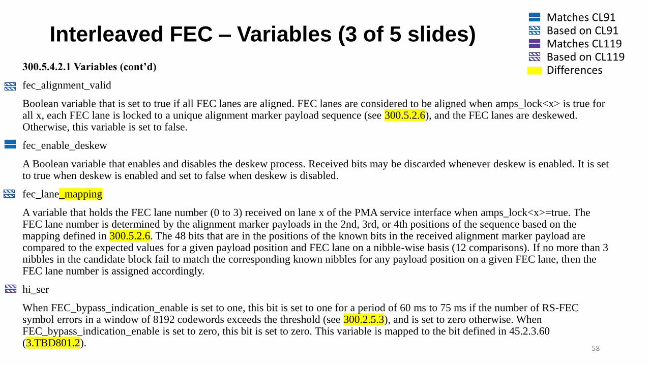
Interleaved FEC – Variables (3 of 5 slides)
58
300.5.4.2.1 Variables (cont’d)
fec_alignment_valid
Boolean variable that is set to true if all FEC lanes are aligned. FEC lanes are considered to be aligned when amps_lock<x> is true for all x, each FEC lane is locked to a unique alignment marker payload sequence (see 300.5.2.6), and the FEC lanes are deskewed. Otherwise, this variable is set to false.
fec_enable_deskew
A Boolean variable that enables and disables the deskew process. Received bits may be discarded whenever deskew is enabled. It is set to true when deskew is enabled and set to false when deskew is disabled.
fec_lane_mapping
A variable that holds the FEC lane number (0 to 3) received on lane x of the PMA service interface when amps_lock<x>=true. The FEC lane number is determined by the alignment marker payloads in the 2nd, 3rd, or 4th positions of the sequence based on themapping defined in 300.5.2.6. The 48 bits that are in the positions of the known bits in the received alignment marker payload are compared to the expected values for a given payload position and FEC lane on a nibble-wise basis (12 comparisons). If no more than 3 nibbles in the candidate block fail to match the corresponding known nibbles for any payload position on a given FEC lane, then the FEC lane number is assigned accordingly.
hi_ser
When FEC_bypass_indication_enable is set to one, this bit is set to one for a period of 60 ms to 75 ms if the number of RS-FEC symbol errors in a window of 8192 codewords exceeds the threshold (see 300.2.5.3), and is set to zero otherwise. When FEC_bypass_indication_enable is set to zero, this bit is set to zero. This variable is mapped to the bit defined in 45.2.3.60 (3.TBD801.2).
Matches CL91Based on CL91Matches CL119Based on CL119Differences

Interleaved FEC – Variables (4 of 5 slides)
59
300.5.4.2.1 Variables (cont’d)
first_pcsl
A variable that holds the PCS lane number that corresponds to the first alignment marker payload that is recognized on a given lane of the PMA service interface. It is compared to the PCS lane number corresponding to the second alignment marker payload that is tested.
reset
Boolean variable that controls the resetting of the RS-FEC sublayer. It is true whenever a reset is necessary including when reset is initiated from the MDIO, during power on, and when the MDIO has put the RS-FEC sublayer into low-power mode.
restart_lock
Boolean variable that is set by the FEC synchronization process to restart the alignment marker lock process on all FEC lanes. It is set to true after 3 consecutive uncorrected codewords are received (3_BAD state) and set to false upon entry into the LOSS_OF_ALIGNMENT state.
rx_align_status
Boolean variable that is set by the alignment lock and deskew function (see 300.5.2.2).
signal_ok
Boolean variable that is set based on the most recently received value of PMA:IS_SIGNAL.indication(SIGNAL_OK). It is true if the value was OK and false if the value was FAIL.
Matches CL91Based on CL91Matches CL119Based on CL119Differences

Interleaved FEC – Variables (5 of 5 slides)
60
300.5.4.2.1 Variables (cont’d)
slip_done
Boolean variable that is set to true when the SLIP requested by the synchronization state diagram has been completed indicating that the next candidate 64-bit block position can be tested.
test_amp
Boolean variable that is set to true when a candidate block position is available for testing and false when the FIND_1ST state is entered.
test_cw
Boolean variable that is set to true when a new FEC codeword is available for decoding and is set to false when the TEST_CW state is entered.
Matches CL91Based on CL91Matches CL119Based on CL119Differences

Interleaved FEC – Functions
61
300.5.4.2.2 Functions
AMP_COMPARE
This function compares the values of first_pcsl and current_pcsl to determine if a valid alignment marker payload sequence has been detected and returns the result of the comparison using the variable amp_match. If current_pcsl and first_pcsl both found a match and indicate the same PCS lane number, amp_match is set to true.
SLIP
Causes the next candidate block position to be tested. The precise method for determining the next candidate block position is not specified and is implementation dependent. However, an implementation shall ensure that all possible block positions are evaluated.
Matches CL91Based on CL91Matches CL119Based on CL119Differences

Interleaved FEC – Counters
62
300.5.4.2.3 Counters
amp_bad_count
Counts the number of consecutive alignment markers that don’t match the expected values for a given FEC lane.
amp_counter
This counter counts the interval of 4096 FEC codewords containing normal alignment marker payload sequences.
cwA_bad_count
Counts the number of consecutive uncorrected FEC codewords for codeword A. This counter is set to zero when an FEC codeword Ais received and cwA_bad is false.
cwB_bad_count
Counts the number of consecutive uncorrected FEC codewords for codeword B. This counter is set to zero when an FEC codeword Bis received and cwB_bad is false.
Matches CL91Based on CL91Matches CL119Based on CL119Differences

Interleaved FEC – State Diagrams (1 of 2 slides)
63
300.5.4.3 State diagrams
The FEC shall implement four alignment marker lock processes in Figure 300-TBD12. An alignment marker lock process operates independently on each lane. The alignment marker lock state diagram shown in Figure 300-TBD12 determines when the FEC has obtained alignment marker lock to the received bit stream for a given lane of the service interface.
Each alignment marker lock process looks for two valid alignment markers 557 056 × 10-bit Reed-Solomon symbols apart, on a per FEC lane basis, to gain alignment marker lock. When the alignment marker lock process achieves lock for a lane, and if a Clause 45 MDIO is implemented, the FEC shall record the FEC lane number received on that lane of the service interface in the appropriate lane mapping register (3.TBD400 to 3.TBD415). Once in lock, a lane goes out of alignment marker lock only when restart_lock is signaled. This occurs when the FEC synchronization process determines that three uncorrectable codewords in a row are seen, or when the alignment marker lock process sees five alignment markers in a row that fail to match the expected pattern on a given lane.
The FEC shall implement the alignment process as shown in Figure 300-TBD13.
Matches CL91Based on CL91Matches CL119Based on CL119Differences

Interleaved FEC – State Diagrams (2 of 2 slides)
64
300.5.4.3 State diagrams
Figure 300-TBD12 "Alignment marker lock state diagram" same as Figure 119-12 "Alignment marker lock state diagram", with following exceptions:
- pcs_lane_mapping<x> change to fec_lane_mapping<x>
Figure 300-TBD13 "FEC alignment state diagram" same as Figure 119-13 "PCS synchronization state diagram", with following exceptions:
- pcs_enable_deskew change to fec_enable_deskew
- pcs_alignment_valid change to fec_alignment_valid
- align_status change to fec_align_statusHeavily
LeveragesClause
119

Thank You!
65