banks monster exhaust system -...
TRANSCRIPT

03/14/13 PN 96553 v.1.0
Banks Monster®
Exhaust System
Chevy/GMC 1500 Silverado 5.3L, Gas/FFV, 2012 Extend Cab Standard 6.5’ Bed
THIS MANUAL IS FOR USE WITH MONSTER EXHAUST SYSTEM 48354
Gale Banks Engineering 546 Duggan Avenue • Azusa, CA 91702 (626) 969-9600 • Fax (626) 334-1743
Product Information & Sales: (888) 635-4565Customer Support: (888) 839-5600 Installation Support: (888) 839-2700
bankspower.com
©2013 Gale Banks Engineering
Owner’sManualwith Installation Instructions

2 96553 v.1.0
If you have any questions concerning the installation of your Banks Monster Exhaust System, please call our Technical Service Hotline at (888) 839-2700 between 7:00 am and 4:00 pm (PT). If you have any questions relating to shipping or billing, please contact our Customer Service Department at (888) 839-5600.
Thank you.
1. Before starting work, familiarize yourself with the installation procedure by reading all of the instructions.
2. The exploded view (Figure 1) provides only general guidance. Refer to each step and section diagram in this manual for proper instruction.
3. Throughout this manual, the left side of the vehicle refers to the driver’s side, and the right side to the passenger’s side.
4. Disconnect the negative (ground) cable from the battery (or batteries, if there are two) before beginning work.
5. Route and tie wires and hoses a minimum of 6” away from exhaust heat, moving parts and sharp edges. Clearance of 8” or more is recommended where possible.
6. When raising the vehicle, support it on properly weight-rated safety stands, ramps or a commercial hoist. Follow the manufacturer’s safety precautions. Take care to balance the vehicle to prevent it from slipping or falling. When using ramps, be sure the front wheels are centered squarely on
the topsides. When raising the front of the vehicle, put the transmission in park, set the parking brake, and block the rear wheels. When raising the back of the vehicle, be sure the vehicle is on level ground and the front wheels are blocked securely.
CAUTION! Do not use floor jacks to support the vehicle while working under it. Do not raise the vehicle onto concrete blocks, masonry or any other item not intended specifically for this use.
7. During installation, keep the work area clean. Do not allow anything to be dropped into intake, exhaust, or lubrication system components while performing the installation, as foreign objects will cause immediate engine damage upon start-up.
Tools Required:
• 1⁄2” and 3⁄8” drive ratchets with standard and metric sockets and 1⁄2” and 3⁄8” drive extension
• Standard and metric combination or open-end wrenches
• Standard screwdriver
• Clean shop towels or rags
• Pry-bar
• Reciprocating saw
Highly recommended tools and supplies:
• Foot-pound torque wrench
• Penetrating oil or light lubricant spray
General Installation Practices
96553 v.1.0 3
For More Information please call (888) 635-4565or Visit us online @ www.bankspower.com
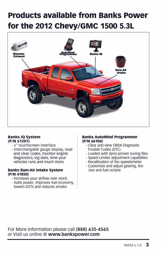
Products available from Banks Power for the 2012 Chevy/GMC 1500 5.3L
Banks iQ System(P/N 61201)
- 5” touchscreen interface - Interchangable gauge display, read and clear codes, monitor engine diagnostics, log data, time your vehicles runs and much more.
Banks Ram-Air Intake System(P/N 41850)
- Increases your airflow over stock. - Adds power, improves fuel economy,
lowers EGTs and reduces smoke.
Banks AutoMind Programmer(P/N 66104)
- Clear and view OBDII Diagnostic Trouble Codes (DTC).
- Loaded with dyno-proven tuning files- Speed Limiter adjustment capabilites- Recalibration of the speedometer- Customize and adjust gearing, tire
size and fuel octane

4 96553 v.1.0
General AssemblyFi
gu
re 1
Ite
m #
De
scri
pti
on
P/N
QTY
1Ex
haus
t C
lam
p, 3
”52
465
3
2H
ange
r C
lam
p, In
term
edai
te53
680
1
3In
term
edia
te p
ipe
5367
91
4M
onst
er M
uffle
r54
005
1
5Re
ar M
uffle
r H
ange
r C
lam
p53
642
1
6Fr
ont,
Tailp
ipe
5363
01
7Re
ar, T
ailp
ipe
5363
41
8B
anks
Dec
als
9600
92
*201
0 5.
3L C
CS
B (
5.8f
t. b
ed)
on
ly, D
o N
ot
rece
ive
2.75
” Ex
hau
st C
lam
p.
96553 v.1.0 5
1. Disconnect the negative (ground) cable from the battery (if there is more than one battery, disconnect both negative cables). Secure the cable so it cannot accidentally come in contact with the post.
2. Raise the vehicle and support it securely with properly weight-rated safety stands, ramps or a commercial hoist. Take care to balance the vehicle to prevent it from slipping or falling. When using ramps, be sure the wheels are centered squarely on the topsides. Place the transmission in park (automatic), set the parking brake and securely block the wheels that are on the ground.
CAUTION: DO NOT WORK UNDER ANY VEHICLE SUPPORTED ONLY BY A JACK. SEVERE INJURY MAY RESULT.
WARNING! The following step may require the use of a torch and/or saw. Proper safety equipment should be used. Failure to use proper safety equipment may result in severe injury.
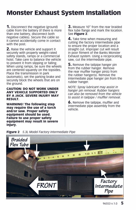
3. Measure 10” from the rear braided flex tube flange and mark the location. See Figure 2.
4. Take time when measuring and cutting the factory intermediate pipe to ensure the proper location and a straight cut. Improper cut will result in poor fitment of the Banks Monster Exhaust system. Using a reciprocating saw, cut the intermediate pipe.
5. Remove the tailpipe hanger pin from the rubber hanger. Remove the rear muffler hanger pin(s) from the rubber hanger(s). Remove the Intermediate pipe hanger pin from the rubber hanger.
NOTE: Spray lubricant may assist in hanger pin removal. Rubber hangers can also be removed from the vehicle to assist in tailpipe / muffler removal.
6. Remove the tailpipe, muffler and intermediate pipe assembly from the vehicle.
Monster Exhaust System Installation
Figure 2 5.3L Model Factory Intermediate Pipe

6 96553 v.1.0
7. Locate the supplied Banks Intermediate pipe. Both ends of Banks intermediate pipe are size differently for different model applications. Fit Banks intermediate pipe over the Factory cut intermediate pipe. If one end does not fit over the Factory pipe try the other end. Insure that Banks intermediate pipe fits over the Factory pipe.
8. Once you have fitted the correct end of Banks intermediate pipe on the factory pipe you will need to cut the other end that did not fit over the factory pipe. Remove the Banks intermediate pipe and measure 3” from the end that did not fit towards the middle of the pipe. See Figure 3. Cut end that did not fit off.
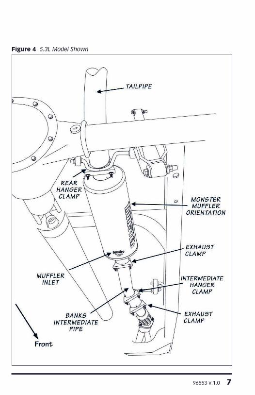
9. Install the internal exhaust clamp on the inlet of Banks intermediate pipe. Install Banks intermediate pipe. Be sure the intermediate pipe jog is orientated as shown in Figure 4. Lightly tighten the Exhaust clamp on the intermediate pipe inlet.
NOTE: All clamps should be positioned at the beginning of the slots (on the 1⁄2 circle punch).
10. Slide the intermediate hanger clamp onto the intermediate pipe and position it next to the rubber hanger. Insert the hanger pin into the vehicles rubber hanger (see Figure 4).
11. Install the Monster Muffler inlet (Note the inlet labeling of the muffler) onto the intermediate pipe outlet. Orient the Monster logo such that is visible from the passenger side and parallel with the frame rail. Align the clamp onto the muffler inlet (see Figure 4).
NOTE: Once the pipe / muffler has been completely engaged in the slip joint, mark the pipe with a scribe or tape for reference when tightening the clamps later in the installation. Mark each slip joint in this fashion.
12. Install the rear muffler hanger clamp onto the Monster Muffler outlet. Insert the hanger pin into the vehicles rubber hanger (see Figure 4).
NOTE: For some models, only one factory rubber hanger is provided for supporting the rear muffler outlet.
13. From the vehicle rear, route the front tailpipe over the rear end. Install the front tailpipe into the Banks
Figure 3 Banks Intermediate pipe
Cut end that did not fit.
96553 v.1.0 7
Figure 4 5.3L Model Shown

8 96553 v.1.0
Muffler outlet. Lightly tighten the rear muffler hanger clamp to secure the front tailpipe. Install the Exhaust clamp onto the front tailpipe outlet. Install the rear tailpipe inlet into the front tailpipe outlet. Start the rear tailpipe hanger pin into the corresponding vehicle rubber hanger. Lightly tighten the exhaust clamp to secure the rear tailpipe.
14. Adjust the tip about 1⁄2” under the body panel, such that the tip position is aesthetically pleasing.
15. Adjust each of the pipes to ensure that all of the hanger pins are parallel with the frame mounted pins
and that the rubber hangers are all positioned slightly forward (See Figure 5). This allows the hangers to be properly positioned once the exhaust reaches operating temperature.
16. With the exhaust positioned properly, begin to evenly tighten the clamps starting with the ones closest to the front of the vehicle and working your way back. Torque the exhaust clamps evenly to 35 ft-lbs. Make sure that each slip is fully inserted (+/-1⁄4”).
17. Remove the protective covering from the tailpipe tip.
Figure 5
96553 v.1.0 9
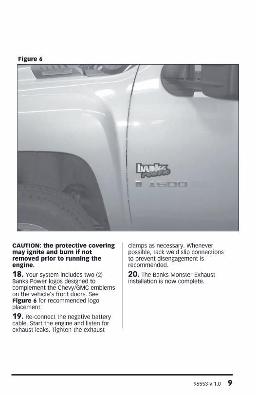
CAUTION: the protective covering may ignite and burn if not removed prior to running the engine.
18. Your system includes two (2) Banks Power logos designed to complement the Chevy/GMC emblems on the vehicle’s front doors. See Figure 6 for recommended logo placement.
19. Re-connect the negative battery cable. Start the engine and listen for exhaust leaks. Tighten the exhaust
clamps as necessary. Whenever possible, tack weld slip connections to prevent disengagement is recommended.
20. The Banks Monster Exhaust installation is now complete.
Figure 6

10 96553 v.1.0
Notes

96553 v.1.0 11
Notes

Gale Banks Engineering 546 Duggan Avenue • Azusa, CA 91702 (626) 969-9600 • Fax (626) 334-1743
Product Information & Sales: (888) 635-4565Customer Support: (888) 839-5600 Installation Support: (888) 839-2700
bankspower.com