banana report
DESCRIPTION
BananaTRANSCRIPT
Open drain output in TIVA c :
General purpose input/output (GPIO) pins on microcontrollers have various modes for both input and output. Input modes may include pull-up or pull-down resistors, hysteresis, or some combination. Output modes can be push-pull, high-drive or open-drain.
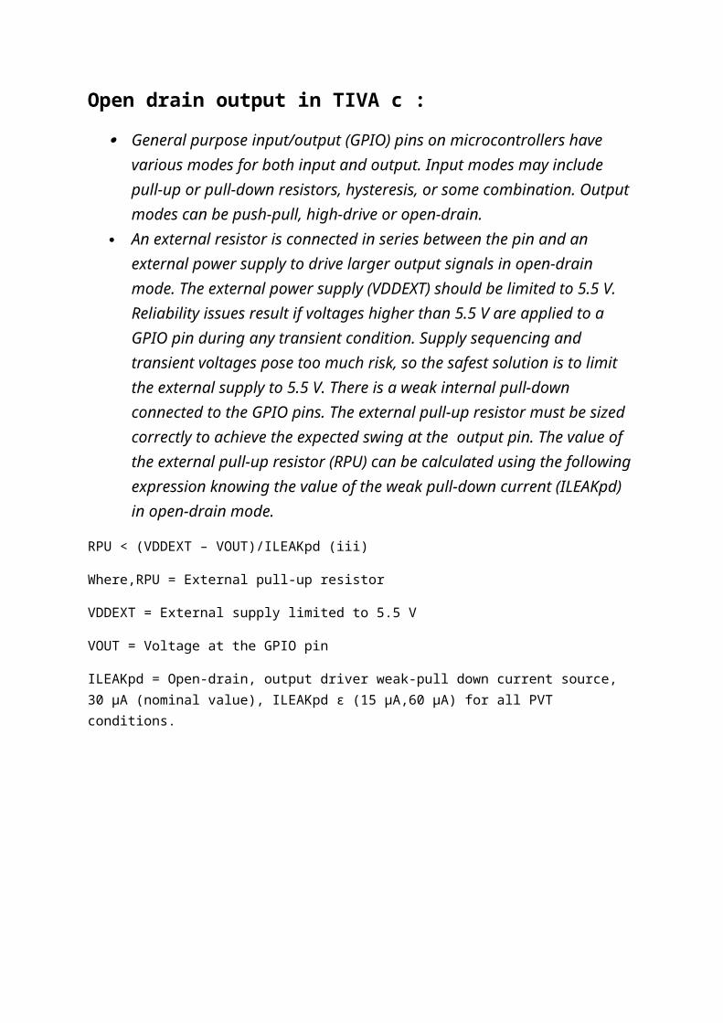
An external resistor is connected in series between the pin and an external power supply to drive larger output signals in open-drain mode. The external power supply (VDDEXT) should be limited to 5.5 V. Reliability issues result if voltages higher than 5.5 V are applied to a GPIO pin during any transient condition. Supply sequencing and transient voltages pose too much risk, so the safest solution is to limit the external supply to 5.5 V. There is a weak internal pull-down connected to the GPIO pins. The external pull-up resistor must be sized correctly to achieve the expected swing at the output pin. The value of the external pull-up resistor (RPU) can be calculated using the following expression knowing the value of the weak pull-down current (ILEAKpd) in open-drain mode.
RPU < (VDDEXT – VOUT)/ILEAKpd (iii)
Where,RPU = External pull-up resistor
VDDEXT = External supply limited to 5.5 V
VOUT = Voltage at the GPIO pin
ILEAKpd = Open-drain, output driver weak-pull down current source, 30 µA (nominal value), ILEAKpd ϵ (15 µA,60 µA) for all PVT conditions.
GPIOs can be connected to a 5-V external voltage source with anexternal pull-up resistor when they are configured as open drain outputs
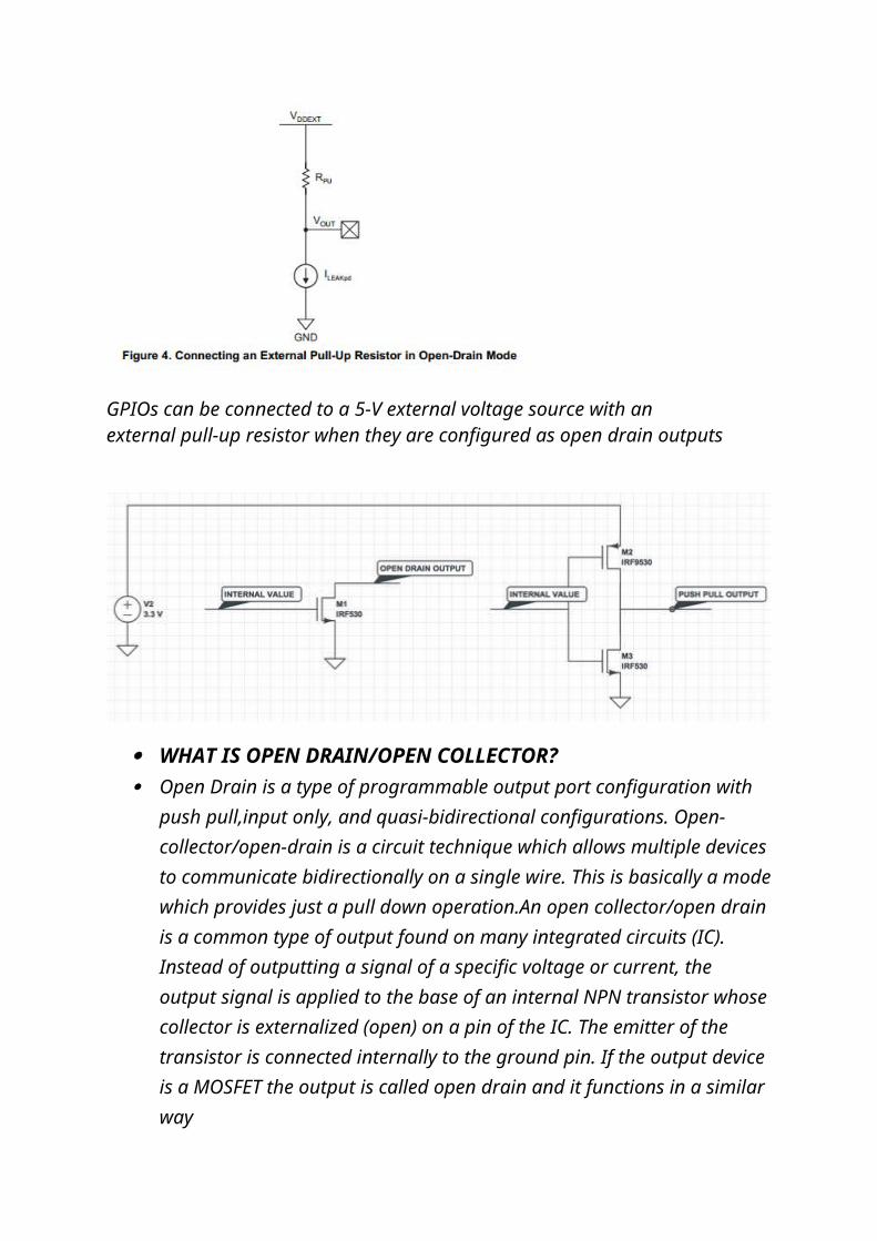
WHAT IS OPEN DRAIN/OPEN COLLECTOR? Open Drain is a type of programmable output port configuration with push
pull,input only, and quasi-bidirectional configurations. Open-collector/open-drain is a circuit technique which allows multiple devices to communicate bidirectionally on a single wire. This is basically a mode which provides just a pull down operation.An open collector/open drain is a common type of output found on many integrated circuits (IC). Instead of outputting a signal of a specific voltage or current, the output signal is applied to the base of an internal NPN transistor whose collector is externalized (open) on a pin of the IC. The emitter of the transistor is connected internally to the ground pin. If the output device is a MOSFET the output is called open drain and it functions in a similar way
FUNCTION:
Open-drain devices sink (flow) current in their low voltage active (logic 0) state, or are high impedance (no current flows) in their high voltage non-active (logic 1) state. These devices usually operate with an external pull-up resistor that holds the signal line high until a device on the wire sinks enough current to pull the line low. Many devices can be attached to the signal wire. If all devices attached to the wire are in their non-active state, the pull-up will hold the wire at a high voltage. If one or more devices are in the active state, the signal wire voltage will be low.
An open-collector/open-drain signal wire can also be bi-directional. Bi-directional means that a device can both output and input a signal on the wire at the same time. In addition to controlling the state of its pin that is connected to the signal wire (active, or non-active), a device can also sense the voltage level of the signal wire. Although the output of a open-collecter/open-
drain device may be in the non-active (high) state, the wire attached to the device may be in the active (low) state, due to activity of another device attached to the wire.
The bi-directional nature of an open-collector/open-drain device is what makes this circuit so important in interconnecting many devices on a common line. The I2C Bus and SMBus uses this technique for connecting up to 127 devices
ADVANTAGE OF OPEN DRAIN CIRCUIT :
1. The control line and output (collector/drain) can use difference voltage level.
2. Increase the output pin power.
APPLICATION :
1 ) It is employed into output port of controllers to reduce the output circuitry. If output port is set into open-drain mode then we don’t require any circuit to pull down the output value of the pin.The open-drain output configuration turns off all pull-ups and only drives the pull-down transistor of the port pin when the port latch contains logic “0”. To be used as a logic output, a port configured in this manner must have an external pull-up, typically a resistor tied to VDD. The pull down for this mode is the same as for the quasi-bidirectional mode. To use an analogue input pin as a high-impedance digital input while a comparator is enabled
2) I2C and SPI protocols use open drain as the physical implementation.At the physical layer, both SCL and SDA lines are open-drain I/Os with pull-up resistors. Pulling such a line to ground is decoded as a logical zero, while releasing the line and letting it flow is a logical one. Actually, a device on a I²C bus ‘only drives zeros’.
At electrical level, there is actually no conflict at all if multiple devices try to put any logic level on the I²C bus lines simultaneously. If one of the drivers tries to write a logical zero and the other a logical one, then the open-drain and pull-up structure ensures that there will be no shortcut and the bus will actually see a logical zero transiting on the bus. In other words, in any conflict, a logic zero always ‘wins’.However, there are situations where an I²C slave is not able to co-operate with the clock speed given by the master and needs to slow down a little. This is done by a mechanism referred to as clock stretching and is made possible by the particular open-drain / pull-up structure of a I²C bus line.
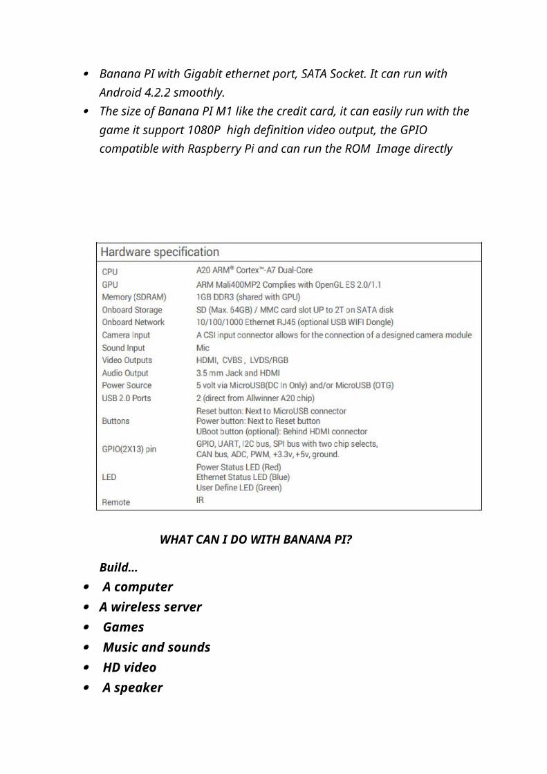
WHAT’S BANANA PI?
It’s an open-source single-board computer. It can run Android 4.4, Ubuntu, Debian, Rasberry Pi Image, as well as the Cubieboard Image. It uses the AllWinner A20 SoC, and has 1GB DDR3 SDRAM,
which published to assistant the Elastos.org open source OS, Banana PI M1 is the dual core Android 4.2 product which more better than the Raspberry Pi.
Banana Pi series run Android,Debian linux,Ubuntu linux, Raspberry Pi imange and cubieboard imange.
Elastos coordinate multi CUP to from the family cloud entirnment which based on the “software/hardware service”
Banana PI hardware: 1Ghz ARM7 dual-core processor, 1GB DDR3 SDRAM, Banana PI with Gigabit ethernet port, SATA Socket. It can run with Android
4.2.2 smoothly. The size of Banana PI M1 like the credit card, it can easily run with the game it
support 1080P high definition video output, the GPIO compatible with Raspberry Pi and can run the ROM Image directly
WHAT CAN I DO WITH BANANA PI?
Build…
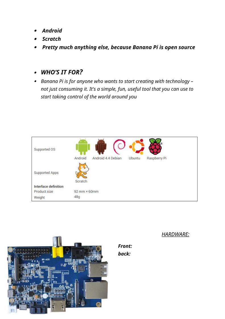
A computer A wireless server Games Music and sounds HD video A speaker Android Scratch Pretty much anything else, because Banana Pi is open source
WHO’S IT FOR? Banana Pi is for anyone who wants to start creating with technology – not just
consuming it. It's a simple, fun, useful tool that you can use to start taking control of the world around you
HARDWARE:
Front: back:
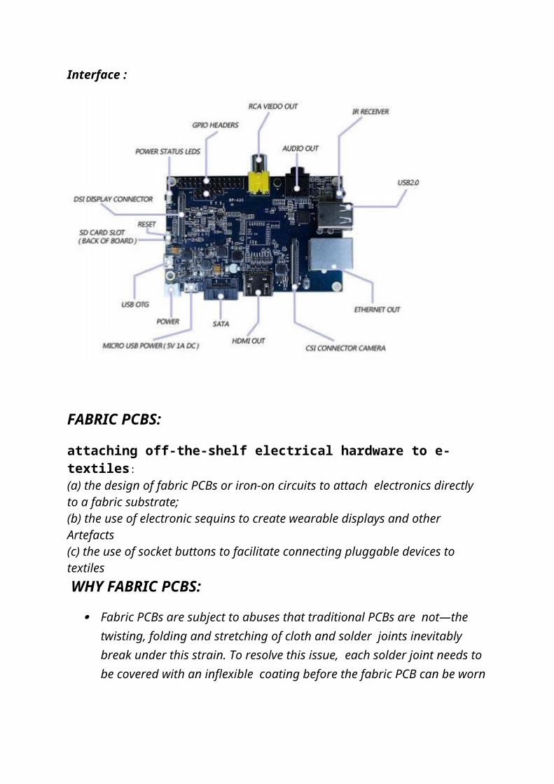
Interface :
FABRIC PCBS:
attaching off-the-shelf electrical hardware to e-textiles: (a) the design of fabric PCBs or iron-on circuits to attach electronics directly to a fabric substrate; (b) the use of electronic sequins to create wearable displays and other Artefacts(c) the use of socket buttons to facilitate connecting pluggable devices to textiles WHY FABRIC PCBS:
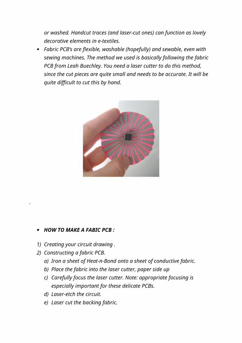
Fabric PCBs are subject to abuses that traditional PCBs are not—the twisting, folding and stretching of cloth and solder joints inevitably break under this strain. To resolve this issue, each solder joint needs to be covered with an inflexible coating before the fabric PCB can be worn or washed. Handcut traces (and laser-cut ones) can function as lovely decorative elements in e-textiles.
Fabric PCB’s are flexible, washable (hopefully) and sewable, even with sewing machines. The method we used is basically following the fabric PCB from Leah Buechley. You need a laser cutter to do this method, since the cut pieces are quite small and needs to be accurate. It will be quite difficult to cut this by hand.
.
HOW TO MAKE A FABIC PCB :
1) Creating your circuit drawing .2) Constructing a fabric PCB.
a) Iron a sheet of Heat-n-Bond onto a sheet of conductive fabric.b) Place the fabric into the laser cutter, paper side upc) Carefully focus the laser cutter. Note: appropriate focusing is especially
important for these delicate PCBs.d) Laser-etch the circuit.e) Laser cut the backing fabric.f) Peel the paper off of the circuit only where you want it to adhere to the
backing fabric.g) Iron the circuit onto the backing fabrich) Peel the excess conductive fabric away from the backing fabric, leaving the
circuit behind3) SOLDERING A FABRIC PCB
APPLICATIONS:
1) Military and defense: Electronic textiles are in research to have strong and efficient soldiers which include the development of integrated sensor arrays and several other embedded sensing technologies which can be integrated
into the soldier’s vehicles, clothing, backpacks or tents. Biofeedback can track a soldier’s vital signs to enhance endurance and overall health, such as socks with pressure sensors that alert you to put your feet up to lower blood pressure. Environmental sensing can detect enemies or potential biochemical threats, such as a woven conductive fabric with embedded button-size microphones that detect the sound of remote objects such as approaching vehicles.Another active research area involves smart, dynamic, responsive, or interactive camouflage: uniforms that possess chameleon-like qualities and can change color when a soldier moves from a desert environment to an urban one.
2) Telemedicine and sports health : There have been strong estimations for the growth of telemedicine, but the production of smart garment medical devices to supplant these predictions is developing much slowly than would be expected. Multi-sensor garments which have been underway for several years are now becoming commercially available.a) The heart rate monitor.b) Multi-sensor physiological monitoringc) Owlet baby monitord) Stretch sense sensors
3) Fashion: A number of designers are continuing to make their mark within wearable technology fashion, using LED light and color to enhance garments for many stage performances and high profile events and occasions. The special effects for these performances are becoming increasingly advanced as the LED lights are being programmed with increasing sophistication.LED fashion garments which have now become commercially available and also other applications of smart textiles within fashion lines are being designed which incorporate inbuilt solar panels for charging technology on-the-go.
table delivered from[1]

figure 2 application in fashion delivered from[2]
References:[1]: http://www.ijettjournal.org/volume-16/number-8/IJETT-V16P274.pdf [2]: http://highlowtech.org/publications/buechley_ISWC_06.pdf[3] Leah Buechley Æ Michael Eisenberg, Fabric PCBs, electronic sequins, and socket buttons: techniques for e-textile craft.[4] https://uwaterloo.ca/stories/waterloo-scientist-advances-researche-textiles