background statement for semi draft document 4319a new...
TRANSCRIPT

Background Statement for SEMI Draft Document 4319A
NEW STANDARD: GUIDE FOR INTERFACING MANUFACTURING EQUIPMENT DESIGN AND FACILITY SYSTEM DESIGN (DESIGN FOR FACILITY) Note: This background statement is not part of the balloted item. It is provided solely to assist the recipient in reaching an informed decision based on the rationale of the activity that preceded the creation of this document. Note: Recipients of this document are invited to submit, with their comments, notification of any relevant patented technology or copyrighted items of which they are aware and to provide supporting documentation. In this context, “patented technology” is defined as technology for which a patent has issued or has been applied for. In the latter case, only publicly available information on the contents of the patent application is to be provided. This document provides guidance and clarification on criteria for manufacturing equipment design and installation. Incorporating the suggestions in this document during the development of the manufacturing equipment will positively affect the factory layout, manufacturing equipment installation, and maximization of layout density. When designing manufacturing equipment to meet the highly complex challenges of today’s semiconductor market, the focus has been on the process capability of the equipment. The capital cost of the manufacturing equipment and the cost to operate and maintain the equipment have been factored into the initial design; however, insufficient thought has been given to the equipment’s effect on the facility and its systems. Consequently; the manufacturing equipment design ignored viewing the costs of the manufacturing equipment and the facility as one. Technology at any price is no longer an acceptable solution. Consequently, equipment purchasers are starting to look at the cost of ownership over the life of the manufacturing equipment and weighing this against the technology performance to arrive at a true Cost of Ownership (COO) estimate. This Guide addresses the facility interface with the manufacturing equipment for architectural, structural, electrical, mechanical (HVAC, exhaust), and process support (cooling water, UPW, chemicals, process effluents, gases). It also discusses the effects of manufacturing equipment on its installation and on its facility and operational costs This ballot will be adjudicated at the meeting of the North America Facilities and Gases Committee at the NA Spring Standards Meetings occurring the week of March 30, 2009 in San Jose, California.
This is a draft document of the SEMI International Standards program. No material on this page is to be construed as an official or adopted standard. Permission is granted to reproduce and/or distribute this document, in whole or in part, only within the scope of SEMI International Standards committee (document development) activity. All other reproduction and/or distribution without the prior written consent of SEMI is prohibited.
Page 1 Doc. 4319A© SEMI®
Semiconductor Equipment and Materials International 3081 Zanker Road San Jose, CA 95134-2127 Phone:408.943.6900 Fax: 408.943.7943
LETT
ER (Y
ELLO
W) B
ALL
OT
DRAFTDocument Number: 4319A
Date: 2/18/2009
SEMI Draft Document 4319A NEW STANDARD: GUIDE FOR INTERFACING MANUFACTURING EQUIPMENT DESIGN AND FACILITY SYSTEM DESIGN (DESIGN FOR FACILITY) 1 Purpose
1.1 When designing manufacturing equipment to meet the highly complex challenges of today’s semiconductor market, the focus has been on the process capability of the equipment. The capital cost of the manufacturing equipment and the cost to operate and maintain the equipment were also factored into the initial design. Insufficient thought has been given to the equipment’s effect on the facility and its systems; the design ignored viewing the costs of the manufacturing equipment and the facility as one.
1.2 Technology at any price is no longer an acceptable solution. Consequently, equipment purchasers are now looking at the cost of ownership (COO) throughout the life of the manufacturing equipment. This results in the use of more stringent equipment selection processes by users to communicate their current manufacturing equipment needs. Equipment suppliers continue to design their products to meet the communicated needs of their customers which can be primarily viewed as: • meeting or exceeding the technology performance requirements, • having reliable performance, • having a competitive purchase price, and • having competitive spares and maintenance headcount requirements.
1.3 Recent changes in market conditions have eroded profit margins at a significantly earlier stage after product release than was previously experienced by semiconductor manufacturers. Manufacturers can no longer rely on the high margins enjoyed by new technology to offset the growing cost of developing and obtaining equipment for the new technologies. A new approach to semiconductor wafer manufacturing cost modeling will need to be developed in which areas of previously ignored costs, such as the effect of manufacturing equipment on facility capital costs, will be included in more detail to fully understand the true total cost of manufacturing equipment ownership. 1.4 This Guide provides guidance and clarification on suggested criteria for manufacturing equipment design and installation. Incorporating the suggestions in this document during the development of the manufacturing equipment will positively affect the factory layout (including tool density) and manufacturing equipment installation.
2 Scope 2.1 This Guide addresses the facility system’s interface with the manufacturing equipment for architectural, structural, electrical, mechanical (HVAC, exhaust), and process support (cooling water, UPW, chemicals, process effluents, gases) utility systems. It also discusses the effect of manufacturing equipment design and configuration on the facility infrastructure and operational costs. 2.2 This Guide focuses how manufacturing equipment design ultimately translates to costs associated with 1) designing and building the wafer fab facility, 2) installing the manufacturing equipment into the facility, and 3) providing ongoing utility services to the equipment. 2.3 Manufacturing equipment and support modules should be designed with the necessary flexibility to meet requirements for use in all regions and applications.
NOTICE: This standard does not purport to address safety issues, if any, associated with its use. It is the responsibility of the users of this standard to establish appropriate safety and health practices and determine the applicability of regulatory or other limitations prior to use.
3 Limitations 3.1 This Guide does not address the process capability of the semiconductor manufacturing equipment. It is the equipment supplier’s responsibility to design the manufacturing equipment to provide the required process capability.
This is a draft document of the SEMI International Standards program. No material on this page is to be construed as an official or adopted standard. Permission is granted to reproduce and/or distribute this document, in whole or in part, only within the scope of SEMI International Standards committee (document development) activity. All other reproduction and/or distribution without the prior written consent of SEMI is prohibited.
Page 2 Doc. 4319A© SEMI®
Semiconductor Equipment and Materials International 3081 Zanker Road San Jose, CA 95134-2127 Phone:408.943.6900 Fax: 408.943.7943
LETT
ER (Y
ELLO
W) B
ALL
OT
DRAFTDocument Number: 4319A
Date: 2/18/2009
3.2 This Guide does not address process effects of using different utilities or designing for different rates of consumption.
4 Referenced Standards and Documents
4.1 SEMI Standards
SEMI E6 — Guide for Semiconductor Equipment Installation Documentation
SEMI E15.1 — Specification for 300mm Tool Load Port
SEMI E49 — Guide for High Purity and Ultrahigh Purity Piping Performance, Subassemblies, and Final Assemblies
SEMI E51 — Guide for Typical Facility Services and Termination Matrix
SEMI E72 — Specification and Guide for 300 mm Equipment Footprint, Height, and Weight
SEMI E76 — Guide for 300mm Manufacturing Equipment Points of Connection to Facility Services
SEMI E78 — Guide to Assess and Control Electrostatic Discharge (ESD) and Electrostatic Attraction (ESA) for Equipment
SEMI E149 — Guide for Equipment Supplier-Provided Documentation for the Acquisition and Use of Manufacturing Equipment
SEMI F47 — Specification for Semiconductor Processing Equipment Voltage Sag Immunity
SEMI F107 — Guide for Process Equipment Adapter Plates
SEMI S2 — Environmental, Health and Safety Guideline for Semiconductor Manufacturing Equipment
SEMI S6 — EHS Guideline for Exhaust Ventilation of Semiconductor Manufacturing Equipment
SEMI S8 — Safety Guidelines for Ergonomics Engineering of Semiconductor Manufacturing Equipment
SEMI S14 — Safety Guidelines for Fire Risk Assessment and Mitigation for Semiconductor Manufacturing Equipment
SEMI S22 — Safety Guideline for the Electrical Design of Semiconductor Manufacturing Equipment
SEMI S23 — Guide for Conservation of Energy, Utilities, and Materials used by Semiconductor Manufacturing Equipment
4.2 International SEMATECH1 Document
99033693A-ENG — SEMATECH Application Guide 2.0 for SEMI S2-93A and SEMI S8-95
4.3 NFPA2 Documents
NFPA 70 — National Electrical Code (NEC)
NFPA 79 — Electrical Standard for Industrial Machinery
4.4 IEST3 Document
IEST RP CC012.2 – Considerations in Cleanroom Design
4.5 Council of the European Union4 Directives
1 International SEMATECH, 2706 Montopolis Drive, Austin, TX 78741, USA. Telephone: 512.356.3500 http://www.sematech.org 2 National Fire Protection Association, 1 Batterymarch Park, Quincy, MA 02269, USA. Telephone: 617.770.3000; Fax: 617.770.0700; http://www.nfpa.org 3 Institute of Environmental Sciences and Technology (IEST), Arlington Place One, 2340 S. Arlington Heights Rd., Suite 100, Arlington Heights, IL 60006-4516, USA. Telephone 847.981.0100. http://www.iest.org 4 Council of the European Union, Rue de la Loi / Wetstraat, 175, B-1048 Brussels, http://europa.eu.int/comm/

This is a draft document of the SEMI International Standards program. No material on this page is to be construed as an official or adopted standard. Permission is granted to reproduce and/or distribute this document, in whole or in part, only within the scope of SEMI International Standards committee (document development) activity. All other reproduction and/or distribution without the prior written consent of SEMI is prohibited.
Page 3 Doc. 4319A© SEMI®
Semiconductor Equipment and Materials International 3081 Zanker Road San Jose, CA 95134-2127 Phone:408.943.6900 Fax: 408.943.7943
LETT
ER (Y
ELLO
W) B
ALL
OT
DRAFTDocument Number: 4319A
Date: 2/18/2009
Directive 98/37/EC of the European Parliament and of the Council on 22 June 1998 on the approximation of the laws of the Member States relating to machinery (Commonly known as the Machinery Directive)
Council Directive 73/23/EEC of 19 February 1973 on the harmonization of the laws of Member States relating to electrical equipment designed for use within certain limits. (Commonly known as the Low Voltage Directive)
Directive 2004/108/EC of the European Parliament and of the Council, of 15 December 2004, on the approximation of the laws of the Member States relating to electromagnetic compatibility (Commonly known as the EMC Directive)
NOTICE: Unless otherwise indicated, all documents cited shall be the latest published versions.
5 Terminology
5.1 Abbreviations and Acronyms
5.1.1 AC — alternating current
5.1.2 AMHS — automated materials handling system
5.1.3 CDA — clean, dry air
5.1.4 CHW — chilled water
5.1.5 CMP — chemical mechanical polishing
5.1.6 COO — cost of ownership
5.1.7 COP — Coefficient of Performance
5.1.8 DI — deionization
5.1.9 ELF — extremely low frequency
5.1.10 EMC — electromagnetic compatibility
5.1.11 EMI — electromagnetic interference
5.1.12 EPOC — equipment point of connection
5.1.13 ESD — electrostatic discharge
5.1.14 HVAC — heating, ventilation, and air conditioning
5.1.15 ME — manufacturing equipment
5.1.16 NEC — National Electrical Code
5.1.17 PCW — process cooling water
5.1.18 PM — preventive maintenance
5.1.19 PV — process vacuum
5.1.20 RF — radio frequency
5.1.21 RO — reverse osmosis
5.1.22 UPS — uninterruptible power supply
5.1.23 UPW — ultrapure water
5.1.24 VOC — volatile organic compound
5.1.25 WWTP — waste water treatment plant

This is a draft document of the SEMI International Standards program. No material on this page is to be construed as an official or adopted standard. Permission is granted to reproduce and/or distribute this document, in whole or in part, only within the scope of SEMI International Standards committee (document development) activity. All other reproduction and/or distribution without the prior written consent of SEMI is prohibited.
Page 4 Doc. 4319A© SEMI®
Semiconductor Equipment and Materials International 3081 Zanker Road San Jose, CA 95134-2127 Phone:408.943.6900 Fax: 408.943.7943
LETT
ER (Y
ELLO
W) B
ALL
OT
DRAFTDocument Number: 4319A
Date: 2/18/2009
5.2 Definitions
5.2.1 adapter plate — a subsystem of the process equipment that contains connections to the chassis as well as to the facility connectors. The adapter plate is intended to be installed and connected to facility connectors before placement of the chassis. [SEMI F107]
5.2.2 accredited testing lab — an independent organization dedicated to the testing of components, devices, or systems; competent to perform evaluations based on established safety standards; and recognized by a governmental or regulatory body
5.2.3 easement space — the floor space that must remain clear to the rear and sides of the piece of equipment (but not in front of the load face plane). This includes safety aisles, ergonomic maintenance access space, component removal space, and room for doors to swing out, (see Figure1). [SEMI E72]
NOTE 1: Figure 1 referenced above is in SEMI E72.
5.2.4 Coefficient of Performance — The ratio of the output heat to the supplied work or
where Q is the useful heat and W is the work required to transfer the heat (e.g. consumed by an air conditioning compressor).
5.2.5 fab — the main cleanroom facility for processing semiconductor wafers. Abbreviation for fabrication facility. [SEMI F107].
5.2.6 footprint — the total area or floor space consumed by a piece of equipment when viewed perpendicular to the area of reference (e.g., normally, when viewed from directly overhead and considering the floor). [SEMI E76]
5.2.7 module — An independently operable unit that is part of a tool or system [SEMI E21]
5.2.8 operation — a process or sequence of acts related to equipment or a system.
5.2.9 reclaim — the reuse of used fluid as feed supply for a process different from the one that discharged it, e.g., RO reject fed into cooling towers.
5.2.10 recycle — the reuse of used fluid as feed supply for the same process that discharged it (e.g. DI rinse returned to front of DI System)
5.2.11 reuse — the secondary use of used fluid with no additional treatment
5.2.12 semiconductor manufacturing equipment (SME) — equipment used to manufacture, measure, assemble, or test products. It includes the equipment that processes substrates (e.g., silicon wafers, reticles), its component parts, and its auxiliary, support or peripheral equipment (e.g., chemical controllers, chemical delivery systems, vacuum pumps). SME also includes other items (e.g., structures, piping, ductwork, effluent treatment systems, valve manifold boxes, filtration, and heaters) specific to and provided with the aforementioned equipment, but does not include such an item if the item is part of a facility and can support more than one piece of SME
5.2.13 subfab — the area below or outside of the cleanroom production area that can be single or multiple levels and may or may not be clean. [SEMI E76]
5.2.14 subsystem — an assembly of two or more components that is manufactured as a single entity. A subsystem must be combined with one or more additional components or subsystems to form a complete system. [SEMI F1]
5.2.15 support equipment — ancillary equipment not part of the process equipment main chassis (e.g. vacuum pumps and chillers that are needed for the manufacturing equipment operation that can be separated from the main chassis) [SEMI F49].

This is a draft document of the SEMI International Standards program. No material on this page is to be construed as an official or adopted standard. Permission is granted to reproduce and/or distribute this document, in whole or in part, only within the scope of SEMI International Standards committee (document development) activity. All other reproduction and/or distribution without the prior written consent of SEMI is prohibited.
Page 5 Doc. 4319A© SEMI®
Semiconductor Equipment and Materials International 3081 Zanker Road San Jose, CA 95134-2127 Phone:408.943.6900 Fax: 408.943.7943
LETT
ER (Y
ELLO
W) B
ALL
OT
DRAFTDocument Number: 4319A
Date: 2/18/2009
6 Introduction to Design for Facility (DFF)
6.1 The design and installation of manufacturing equipment in a wafer fab has direct and indirect effects on the environment and utility consumption. When manufacturing equipment utility and design requirements are outside of the normal capabilities of the facility support systems, the project’s schedule and budget are often affected. This guideline provides suggestions to manufacturing equipment and equipment module designers regarding areas where following these ideas would improve the integration of manufacturing equipment into a fabrication facility. Designing manufacturing equipment and support modules to integrate into worldwide facilities presents numerous challenges. Many of the suggestions in this guide are a result of challenges that have been identified when integrating manufacturing equipment and modules into a facility. These challenges include:
• Electrical power voltages and frequencies differ around the world, • Utility systems have been oversized due to inaccurate or uninvalidated utility values, • Nameplate ratings in many cases do not reflect actual operating characteristics, and • Utility specifications exceed those recommended in SEMI E51.
NOTE 2: Related Information 1 contains effect scenarios illustrating several of these concerns.
6.2 Equipment designers should consider the following requirements from other SEMI documents:
6.2.1 Provide documentation for interfacing with facility utilities as indicated in SEMI E6. (See also SEMI E149.)
6.2.2 Guidance for providing documentation for interfacing with fire protection systems is provided in SEMI S14.
6.2.3 Footprint drawings as shown in SEMI E72 document the arrangement and clearance needs of the equipment.
6.2.4 Guidance for interfacing with facility utilities is provided in SEMI E51.
6.2.5 Where feasible, suppliers should provide internal manifolding of supply utilities to reduce the number of facility connections to the manufacturing equipment and regulate pressures at the manifold. (See SEMI E49.) This provides internal control of the process equipment.
6.2.6 Utility reduction strategies (See SEMI S23) should be designed into the manufacturing equipment to meet semiconductor industry energy reduction goals. When utility requirements are overstated, facility costs and operating costs tend to be increased.
6.2.7 Suppliers should provide measured utility values so support utility capacities can be sized correctly. (See SEMI E6 and S23.) Matching manufacturing equipment, maintenance, environmental requirements and operating loads to facility infrastructure system capacities is necessary to improve system utilization and reduce facility capital and operating costs.
6.2.8 Suppliers should provide equipment that meets the relevant requirements of SEMI S2 and S8.
NOTE 3: Manufacturing equipment should be designed to support environmental principles, such as separating waste streams to support reuse, reclaim and recycling strategies, where these methods are feasible. Even with these recommendations, manufacturing equipment and support modules should be designed with the flexibility to meet requirements for use in all regions and applications.
6.3 The utility types and systems covered in this guide are listed in Table 1.

This is a draft document of the SEMI International Standards program. No material on this page is to be construed as an official or adopted standard. Permission is granted to reproduce and/or distribute this document, in whole or in part, only within the scope of SEMI International Standards committee (document development) activity. All other reproduction and/or distribution without the prior written consent of SEMI is prohibited.
Page 6 Doc. 4319A© SEMI®
Semiconductor Equipment and Materials International 3081 Zanker Road San Jose, CA 95134-2127 Phone:408.943.6900 Fax: 408.943.7943
LETT
ER (Y
ELLO
W) B
ALL
OT
DRAFTDocument Number: 4319A
Date: 2/18/2009
Table 1 Service Categories
Service Category Number#1 Service Category Description
100 Equipment Identification
200 Environmental Conditions
300 Physical Characteristics
400 Electrical Power
500 Water
600 Bulk Chemicals
700 Drains
800 Gases
900 Vacuum
1000 Exhaust #1 See SEMI E6 for information on the Service Categories.
7 Environmental Conditions (Service Category 200) 7.1 Environmental conditions section of SEMI E6 includes cleanliness class, temperature, humidity, heat loads, vibration requirements, lighting, ESD, and electromagnetic noise. Provide a list of environmental requirements as specified in SEMI E6.
7.2 Support equipment should be designed to allow flexibility for the user and installer, but not require a cleanroom environment.
7.3 Equipment should conform to SEMI E78 and state level of compliance and minimize static charge on the manufacturing equipment or the wafer carrier. Designers should consider using static dissipative material on any part that contacts the wafer or is within 300 mm (one foot) of the wafer path. If the equipment uses permanent magnets, electromagnets, or draws 100 amps or more per phase, suppler and user should agree on Extreme Low Frequency EMI (ELF-EMI) criteria.
7.4 Vibration Isolation — Adequate vibration mitigation systems should be considered as an option to the end user or included in equipment to allow installation and operation in areas without strict vibration performance characteristics or as mutually agreed up between supplier and end user.
8 Physical Characteristics (Service Category 300) 8.1 Physical characteristics include manufacturing equipment and module length, width, height, weight, floor loading conditions, layout and easement space. Provide a list of physical characteristics as specified in SEMI E6.
8.2 In order for manufacturing equipment configurations to be optimal from a layout and installation perspective, both in the fab and subfab areas, the equipment size, configuration and integration should be determined and designed in the beginning stages. It is important to view the manufacturing equipment and its support modules as part of the overall factory equipment set, not a stand alone piece of manufacturing equipment. The equipment design engineers should understand how their subsystem or module designs will affect the integration and final configuration of the manufacturing equipment, both in the fab and subfab, and with the entire production equipment set.
8.3 Move in weights should be considered (see SEMI E72). Manufacturing equipment should be as light as practical. Weight should be distributed as evenly as possible to limit large concentrated loads on floors. (See SEMI E72.)
8.4 Move in dimensions of the manufacturing equipment should not exceed SEMI E72 requirements. Where practical, manufacturing equipment should disassemble into small, efficient pieces to allow equipment movement in areas without large freight elevators or oversized move-in corridors.

This is a draft document of the SEMI International Standards program. No material on this page is to be construed as an official or adopted standard. Permission is granted to reproduce and/or distribute this document, in whole or in part, only within the scope of SEMI International Standards committee (document development) activity. All other reproduction and/or distribution without the prior written consent of SEMI is prohibited.
Page 7 Doc. 4319A© SEMI®
Semiconductor Equipment and Materials International 3081 Zanker Road San Jose, CA 95134-2127 Phone:408.943.6900 Fax: 408.943.7943
LETT
ER (Y
ELLO
W) B
ALL
OT
DRAFTDocument Number: 4319A
Date: 2/18/2009
8.5 Space Optimization (Fab & Subfab Layout Opportunities)
8.5.1 When an integrated piece of equipment is being designed, designers should consider each process module or subsystem (e.g,. equipment main frame, RF units, vacuum pumps) as part of a system that uses fab and subfab floor space.
8.5.2 Considering using standard equipment/footprint rectangular frames. A rectangular frame is preferable from a layout efficiency perspective, enabling increased dense-packing. (See Figures 1 and 2.)
Figure 1
Rectangular Footprint Equipment Frames

This is a draft document of the SEMI International Standards program. No material on this page is to be construed as an official or adopted standard. Permission is granted to reproduce and/or distribute this document, in whole or in part, only within the scope of SEMI International Standards committee (document development) activity. All other reproduction and/or distribution without the prior written consent of SEMI is prohibited.
Page 8 Doc. 4319A© SEMI®
Semiconductor Equipment and Materials International 3081 Zanker Road San Jose, CA 95134-2127 Phone:408.943.6900 Fax: 408.943.7943
LETT
ER (Y
ELLO
W) B
ALL
OT
DRAFTDocument Number: 4319A
Date: 2/18/2009
Figure 2
Rectangular Equipment Configurations
8.5.3 Consider using an aspect ratio with greater depth than width. The concept here is to fit more equipment into a cleanroom bay. Typically, due to AMHS alignment requirements, more layout flexibility is available in depth than width. (See Figure 3)

This is a draft document of the SEMI International Standards program. No material on this page is to be construed as an official or adopted standard. Permission is granted to reproduce and/or distribute this document, in whole or in part, only within the scope of SEMI International Standards committee (document development) activity. All other reproduction and/or distribution without the prior written consent of SEMI is prohibited.
Page 9 Doc. 4319A© SEMI®
Semiconductor Equipment and Materials International 3081 Zanker Road San Jose, CA 95134-2127 Phone:408.943.6900 Fax: 408.943.7943
LETT
ER (Y
ELLO
W) B
ALL
OT
DRAFTDocument Number: 4319A
Date: 2/18/2009
Figure 3
Aspect Ratio for Manufacturing Equipment
8.5.4 Consider rectangular equipment (equipment footprints) without protrusions on the sides, front or back. If possible, feed all connections to the bottom (or to the top for exhaust in certain cases) of the equipment. (See SEMI E76.)
8.5.5 Consider stacking process modules in the cleanroom so the equipment is taller, rather than deeper or wider. Minimize the overall assembled height of equipment in the fab, including any top utility connections or easement space, (see SEMI E72). Consideration of equipment maintenance will also influence maximum stacking height. Consider fall protection for designs that require installation or maintenance activities standing on surfaces more than 1.2 meters (4 feet) above the surrounding floor.
8.5.6 For factories with one or more subfabs, consider optimizing the subfab space utilization by using process modules integrated into a common block/rack, e.g., have similar or common modules stacked up to the maximum permitted by SEMI E72 in the subfab .
8.5.7 Subsystem designers should try to minimize connections for common block/rack components, for example, a chiller rack containing multiple chillers may be designed such that it has internal manifolds and one pair of facility process cooling water connections.
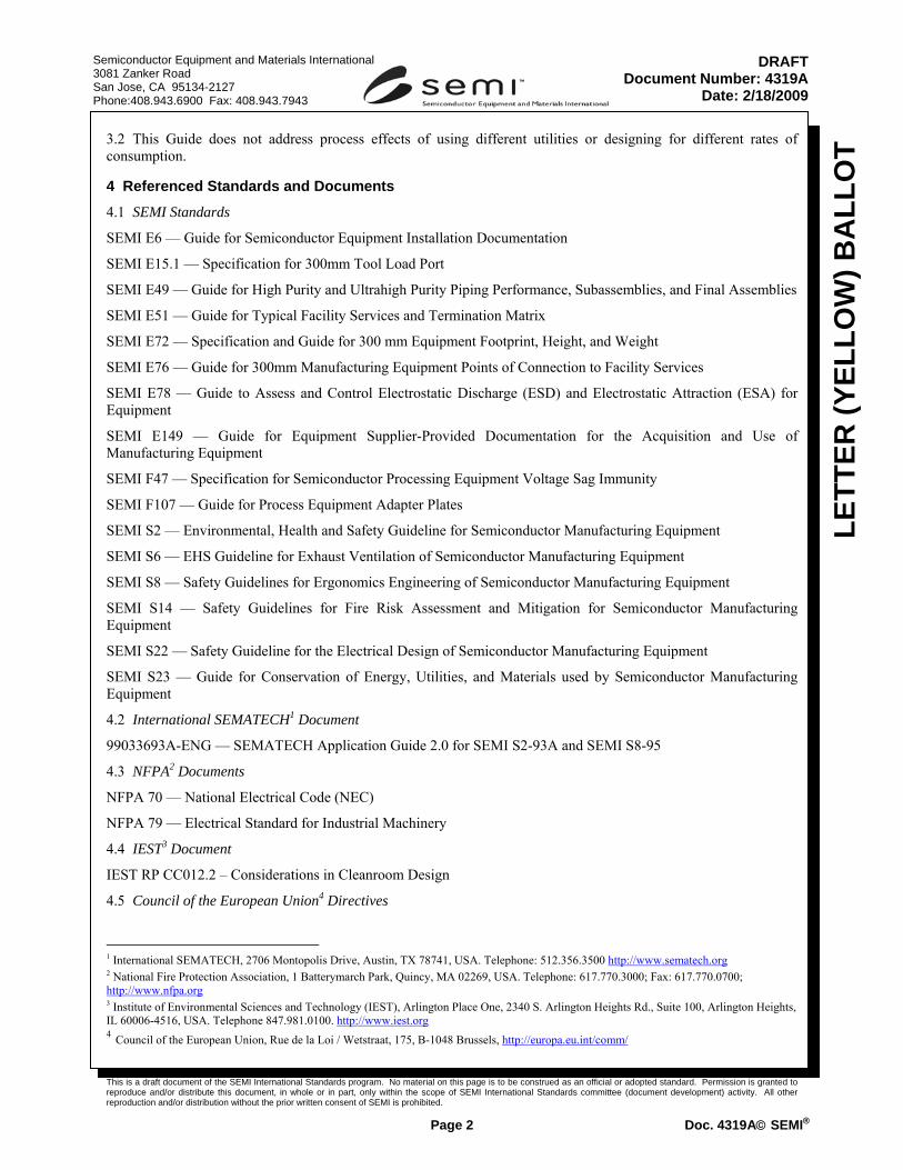
8.5.8 Consider placing all subsystems, such as AC distribution box, RF generator, etc that do not require a cleanroom environment (i.e. temperature, humidity, cleanliness, etc), or close proximity to the tool for process reasons in the subfab to optimize both fab and subfab layout. The support modules should be designed as an integrated solution so that an equal balance of floor space can be obtained. (See Figure 4.)
NOTE 4: Under ideal conditions, all subfab modules would be placed directly below the cleanroom equipment and occupy a space less than 75% of its corresponding cleanroom footprint. The 25% reduction allows for facility systems, columns and safety equipment in the subfab. Both fab and subfab easement space are included as part of footprints.
This is a draft document of the SEMI International Standards program. No material on this page is to be construed as an official or adopted standard. Permission is granted to reproduce and/or distribute this document, in whole or in part, only within the scope of SEMI International Standards committee (document development) activity. All other reproduction and/or distribution without the prior written consent of SEMI is prohibited.
Page 10 Doc. 4319A© SEMI®
Semiconductor Equipment and Materials International 3081 Zanker Road San Jose, CA 95134-2127 Phone:408.943.6900 Fax: 408.943.7943
LETT
ER (Y
ELLO
W) B
ALL
OT
DRAFTDocument Number: 4319A
Date: 2/18/2009
Figure 4
Equipment Footprint
8.6 Equipment designs should be standardized using an interchangeable file format, to enable ease of design layout transfer and inclusion of appropriate utility and connection tables that can be extracted automatically into customer databases for further processing, e.g., layout analysis or utility capacity planning.
NOTE 5: 3D models of equipment are an effective way for suppliers to assist end users and planning facility layout and connections. Interchange formats such as IGES and STP can be used for this.
8.7 In order to optimize subfab space usage, manufacturing equipment designers should try to minimize the use of subfab floor space where feasible. Techniques for reducing subfab footprint include making modules stackable and manifolding vacuum for load locks and transfer chambers.
8.8 Easement Space
8.8.1 In order to optimize easement space, consider using rectangular layout for the manufacturing equipment or support modules without any protrusions. Doors that swing out should open 90 degrees within an easement space consistent with the access criteria of SEMI S8 (a minimum of 690 mm (27 in.)).
NOTE 6: Other applicable safety codes may require more clearance.
8.8.2 Designers should consider the effect of electrical clearances and maintenance requirements in the layout of equipment. For example, if a disconnect switch is needed in the cleanroom to perform hazardous energy isolation of subfab equipment without exiting and re-entering the cleanroom, the integration of this switch with the rest of the electrical equipment can minimize the overall equipment footprint (actual equipment area plus easement/maintenance clearances).
NOTE 7: Easement space may be code driven and require certain minimum clearance distances. SEMI S8 also has criteria regarding space for operators and maintenance personnel.
8.8.3 When practical minimize maintenance easement spaces which are in confined spaces or which are on top (over 1.2 meters (4 feet)) of the manufacturing equipment or support modules as these can result in safety

This is a draft document of the SEMI International Standards program. No material on this page is to be construed as an official or adopted standard. Permission is granted to reproduce and/or distribute this document, in whole or in part, only within the scope of SEMI International Standards committee (document development) activity. All other reproduction and/or distribution without the prior written consent of SEMI is prohibited.
Page 11 Doc. 4319A© SEMI®
Semiconductor Equipment and Materials International 3081 Zanker Road San Jose, CA 95134-2127 Phone:408.943.6900 Fax: 408.943.7943
LETT
ER (Y
ELLO
W) B
ALL
OT
DRAFTDocument Number: 4319A
Date: 2/18/2009
requirements, e.g. fall protection and potential confined space permitting due to hazardous production materials. SEMI E51 specifies dimensions and exclusion zones for load.
9 Electrical Power (Service Category 400) and Communication Connections
9.1 Electrical systems include power, critical power and communication systems. A complete list of electric utilities should be included in the equipment SEMI E6 data sheet.
9.2 Equipment should work with and adjust to both 50 Hz and 60 Hz without affecting system performance.
9.3 The equipment supplier should specify which interconnect cables may be routed in a common raceway and which ones must be in their own raceways (e.g. noise/isolation issues, inadequate insulation)
9.3.1 Bundling cables for different types of electrical systems is limited by electrical codes. In general, cables or wires may be bundled or run in the same raceway only if each of the cables or wires has insulation that has been approved for the highest voltage of any wire in the bundle or raceway. (See SEMI S22.)
NOTE 8: For example, it is permissible to run a 208 V AC power cable in the same raceway as a 24V DC signal cable, as long as the signal cable insulation has been approved for use above 208V. (It might not be desirable to do this for noise reasons, but that’s a separate consideration.) However, although it is appropriate, in most cases, to use 150V insulated wire for a 24V DC signal cable, such a cable would need to be run separately from the 208V AC power cable.
9.4 In some jurisdictions, equipment must be accepted by local inspectors before electric power may be connected. “SME suppliers should prepare a data package to support this inspection and sign-off (e.g. detailed electrical schematics, electrical component ratings, test reports showing previous testing completed, etc.).”
9.4.1 In North America equipment should either be listed by an accredited testing lab (ATL) or field labeled by an organization that is accepted by that jurisdiction. When equipment is listed, the ATL determines which standard is appropriate. For field labeling, the supplier has some additional alternatives, such as NFPA79, but the choice must be acceptable to the locally accepted organization.
NOTE 9: In the past, many users have required that equipment comply with the SEMATECH Application Guide to SEMI S2-93A. There is no equivalent SEMATECH Application Guide for SEMI S2-0200 and later. Many end users now specify SEMI S22 in place of the application guide.
9.5 Suppliers should try to use standardized connections or terminals that can be field installed instead of highly specialized cable terminations. Alternatively, they can supply the specialized connectors or cables prior to the equipment arrival in order to minimize the need for cable storage boxes that require additional space, cause heat buildup, and become contamination collection areas.”. Specialty cables should be limited to situations where a change of cable will affect the process, such as RF generator cables.
9.6 Grounding is necessary to limit the amount of radio frequency noise and interference in the manufacturing process. ME suppliers should coordinate with the user on grounding requirements, especially for frame ground requirements to a reference ground grid. Any default frame ground connection points should be clearly identified in the installation documentation including the method of attachment. (Note: The removal of paint and other coatings and/or drilling in the cleanroom in order to provide for ground bonding is generally unacceptable)
9.7 Interconnect cables that must pass through a wall, a raised floor, or openings in a concrete surface may have requirements beyond those of the cables inside equipment and above the floor. SME supplier should coordinate with the user before shipment to determine the requirements and verify that the wiring provided that runs through the facility meets the local requirements (such as TC rated cable for the NEC). Designers should consult the relevant code about method of supporting the cables
9.8 Hazardous Energy Isolation — Hazardous energy isolation (HEI, formerly known as “Lockout/Tagout”) is required to reduce the risk of injuries from unexpected startup of equipment or release of stored energy in the equipment to the workers performing service on equipment. Equipment that is de-energized should be rendered inoperative and should have tags attached at all points where the equipment can, in normal operation, be energized. Hazardous energy isolation capability should be provided for all levels necessary to perform service or maintenance safely on manufacturing equipment.
9.9 Suppliers should consult with end users regarding compliance with SEMI F47. If compliance is requested, document compliance with SEMI F47 by testing as specified in that document.

This is a draft document of the SEMI International Standards program. No material on this page is to be construed as an official or adopted standard. Permission is granted to reproduce and/or distribute this document, in whole or in part, only within the scope of SEMI International Standards committee (document development) activity. All other reproduction and/or distribution without the prior written consent of SEMI is prohibited.
Page 12 Doc. 4319A© SEMI®
Semiconductor Equipment and Materials International 3081 Zanker Road San Jose, CA 95134-2127 Phone:408.943.6900 Fax: 408.943.7943
LETT
ER (Y
ELLO
W) B
ALL
OT
DRAFTDocument Number: 4319A
Date: 2/18/2009
NOTE 10: The SEMI F47 standard testing strongly discourages the addition of internal UPS equipment on the normal power feed and documents the components that require continuous feed. Continuous power provisions add complexity and are more costly than normal power systems. If UPS units are required to meet the F47 testing standard, use only industrial grade units. Any UPS must be maintainable and robust and the required testing and maintenance must be included in the equipment maintenance requirements.
9.10 The supplier should consider accommodating the various voltage configurations for US, Europe, and Asia regions. This can be achieved either thru the addition of multi-tap inputs or outputs on an input transformer or using components rated for the range of voltages required.
10 Water Systems (Service Category 500)
10.1 Water utilities include all utilities where the composition of such is primarily water. These utilities include DI water, ultrapure water, cooling or heating heat transfer fluids, industrial water, and fire protection water. A complete list of water utilities should be included in the equipment SEMI E6 data sheet.
10.2 Heat transfer Systems — These include conductive and nonconductive fluids, cold and hot fluids (relative to cleanroom temperature), and fluids at various pressures from atmospheric to high pressures (> 2MPa). Subsystems for cold or hot fluids may need insulation; subsystems for high pressure fluids may need relief ports or heavy duty wall thickness. Subsystems for some non-conducting fluids may also need electrical isolation.
10.3 Provide standardized points of connection locations (See SEMI E51.) and internal distribution piping (See SEMI E49.).
10.4 Design the manufacturing equipment’s cooling system to optimize heat exchanger performance and improve heat exchanger COP. (e.g., a larger temperature differential between supply and return). This will result in lower flow rates and lower pressure drops reducing the pumping energy used to provide equipment cooling.
10.5 Employing higher temperature cooling water, such as 30○C (85○F), in lieu of the typical 13○C (55○F) can result in a higher COP resulting in considerable energy saving. Higher cooling water temperature allows the PCW to be cooled either with return chilled water (from air handling units) or by evaporative processes in most climates (with a closed fluid cooler). Using chilled water return allows lower flow rates for the chilled water system and raises the overall CHW temperature differential, which in turn may raise PCW chiller COP. Evaporative fluid coolers with COPs of 15 or higher significantly lower the operating cost of generating PCW, as compressor energy is not required.
10.5.1 Use of higher temperature cooling water should not compromise process requirements
10.5.2 Use Process Cooling Water for manufacturing equipment cooling rather than ambient air heat dissipation. PCW, because of its higher specific heat, is more efficient and it is less costly to remove heat through thermal transfer to water than through the HVAC and exhaust system.
10.6 Suppliers should try to use standardized connections within the same equipment rather that mixing of connectors (e.g. NTP fittings mixing with DIN Fittings)
11 Chemical Systems (Service Category 600)
11.1 Chemical services include concentrated and dilute chemicals and proprietary slurries used in CMP. A complete list of Chemical Utilities should be included in the equipment SEMI E6 data sheet.
11.1.1 For internal and interconnect piping, consideration should be made of proper sizing of the primary carrier for low pressure drops and increased flow characteristics.
11.2 The point of connection to the equipment or chemical delivery lines should accommodate integral secondary containment requirements. The equipment cabinet should be designed as a containment vessel where hazardous fluids are present in the area of the connection(s).
11.3 Standardized points of connection locations (See SEMI E51.) and internal distribution piping (See SEMI E49.2, E49.4 and E49.5.) should be provided.

This is a draft document of the SEMI International Standards program. No material on this page is to be construed as an official or adopted standard. Permission is granted to reproduce and/or distribute this document, in whole or in part, only within the scope of SEMI International Standards committee (document development) activity. All other reproduction and/or distribution without the prior written consent of SEMI is prohibited.
Page 13 Doc. 4319A© SEMI®
Semiconductor Equipment and Materials International 3081 Zanker Road San Jose, CA 95134-2127 Phone:408.943.6900 Fax: 408.943.7943
LETT
ER (Y
ELLO
W) B
ALL
OT
DRAFTDocument Number: 4319A
Date: 2/18/2009
11.4 For slurries, the designer should consider the need for removal of the primary and secondary carrier connections at the equipment, in the event the slurry hardens and prevents flow into the equipment. Consideration should be given to the full replacement of the primary transport carrier in this event.
12 Drain Systems (Service Category 700)
12.1 Drain systems are typically gravity drains and contain hazardous and non-hazardous fluids, including acid waste, solvent waste, industrial waste, concentrated acid, fluoride waste, DI reclaim, HF reclaim, and slurry waste. A complete list of drain utilities should be included in the equipment SEMI E6 data sheet.
12.2 Design the manufacturing equipment to allow for fluid recycling, reclaim, or reuse options; e.g., acid reclaim for reuse in other industry applications or extraction of precious metals from the waste stream.
12.3 Segregate effluent streams for different chemistries (See SEMI S2 and E51.). Common drains limit the ability to separate dilute rinse waters to a segregated drain for reclaim and reuse and limit the ability to separate concentrated waste for treatment and recycling purposes.
NOTE 11: Related Information 1 contains, in § R1-2, an example of this concern.
12.4 The point of connection of the equipment drains to the facility should be made within the cabinet of the equipment. The equipment cabinet should be designed as a containment vessel where hazardous fluids are present in the area of the connection(s) to comply with double containment requirements.
13 Gas Systems (Service Category 800)
13.1 Gas systems include those providing bulk gases (e.g., nitrogen, oxygen, argon, hydrogen, helium and compressed air) and specialty gases (corrosive, flammable, pyrophoric, oxidizer, toxic, or inert gases and gas mixtures). Purity and physical properties of these gases will vary and supply and delivery equipment & piping should be designed for each utility as needed to meet relevant national and international standards, codes and user requirements. A complete list of gas utilities should be included in the equipment SEMI E6 data sheet.
13.2 Consider substitution of compressed dry air (CDA) for nitrogen (N2) for non-process applications when processes and safety allow.
NOTE 12: N2 is generally more costly than CDA and can present an asphyxiation risk.
13.3 Supply pressure requirements for purge and service gases, such as N2 and CDA, should be specified to reduce the risk of cross-contamination and to accommodate the use of typical supply systems less than 1.7 MPa (250 psig).
13.4 Where feasible, provide internal manifolding of supply utilities to reduce the number of facility connections to the manufacturing equipment and regulate pressures at the manifold. (See SEMI E49.). This provides internal control for the process requirements.
13.5 When evaluating gas purity requirements, determine through evaluations and discussions with equipment users, whether internal point-of-use purifiers may be more cost effective than fab-wide purification for any particular process function.
13.6 Interconnection of gas delivery piping often requires leak and purity integrity verifications. These tests require isolation and test port functionality that should be included at the entrance point to the equipment gas manifolds.
14 Vacuum Systems (Service Category 900)
14.1 Vacuum systems include centralized or distributed vacuum utilities and forelines associated with local vacuum pump systems (e.g., process, load lock, and transfer pumps). Vacuum utilities may vary from low pressure of 0.1 Pa to ultrahigh vacuum of 10-6 Pa. A complete list of vacuum utilities should be included in the equipment SEMI E6 data sheet.
14.2 For centralized systems, such as Process Vacuum, provide maximum vacuum quantities and required operating conditions which affect the facility services. When localized systems are provided, such as process, load lock, or transfer pumps, provide operational characteristics allowing the proper sizing of interconnecting forelines and power requirements for the facility infrastructure sizing. (See SEMI E51.)

This is a draft document of the SEMI International Standards program. No material on this page is to be construed as an official or adopted standard. Permission is granted to reproduce and/or distribute this document, in whole or in part, only within the scope of SEMI International Standards committee (document development) activity. All other reproduction and/or distribution without the prior written consent of SEMI is prohibited.
Page 14 Doc. 4319A© SEMI®
Semiconductor Equipment and Materials International 3081 Zanker Road San Jose, CA 95134-2127 Phone:408.943.6900 Fax: 408.943.7943
LETT
ER (Y
ELLO
W) B
ALL
OT
DRAFTDocument Number: 4319A
Date: 2/18/2009
14.3 The equipment designer should coordinate the equipment mainframe support or peripheral equipment to allow for vertical stacking or equipment compression, reducing the footprint of the equipment within the subfab or fab. Easements or maintenance access should be considered when addressing the placement of the racks. The mainframe and peripheral equipment supplier should consider whether the load lock or transfer pump can operate more than one equipment process of the mainframe equipment.
14.4 Forelines should be kept to a maximum allowable length when addressing the placement of localized vacuum racks. The equipment designer should consider the need for heating and insulation of the forelines when the racks are placed within the subfab and fab areas. Utility needs should be communicated using the SEMI E6 or E51 data sheets.
14.5 The equipment designer should consider conveyance of chemical process wastes when centralized vacuum systems are used. P-Traps should be omitted from use on these specialized vacuum systems.
15 Exhaust Systems (Service Category 1000)
15.1 The major types of exhaust systems utilities are heat exhaust, general exhaust, acid or scrubbed exhaust, solvent exhaust, and ammonia exhaust. Process specific exhaust systems, such as for concentrated toxic materials, are incorporated as necessary.
15.2 Exhaust ventilation of semiconductor manufacturing equipment should conform to SEMI S6.
15.3 Minimize exhaust flow and pressure where feasible. Reducing exhaust flows reduces the load on the site exhaust abatement systems. (See SEMI E51.).
15.4 Segregate hazardous exhaust streams from general heat exhaust. Segregating exhaust streams that contain hazardous substances allows semiconductor manufacturers to route only what is required to abatement systems. This will significantly reduce energy cost otherwise required for scrubbers, VOC abatement devices, fan static pressure, etc. Segregation may require more than one exhaust connection for the equipment and the careful design of the equipment exhaust passages to segregate contaminated or hazardous exhaust from non-hazardous exhaust.
15.5 For multiple points of use for the same type of exhaust within a piece of equipment, manifold and balance the exhaust internally and provide one point of connection for the exhaust to the facility.
15.6 Exhausted enclosures should be designed and built (e.g., seal penetrations and panel joints) to minimize leakage
15.7 Consider designs that allow for recycling of exhaust to prevent exhausting heat so that it must be removed by the cleanroom HVAC system. Consider using a liquid heat exchanger.
15.8 Size the ductwork/dampers to allow for some adjustment (higher & lower) within the facility. Use standard-sized tapered duct connections to reduce static pressure loss and potential for turbulent airflow.
15.9 Design the capability to idle or shut down supplemental exhaust (e.g., exhaust only required during PM,) when not in use.

This is a draft document of the SEMI International Standards program. No material on this page is to be construed as an official or adopted standard. Permission is granted to reproduce and/or distribute this document, in whole or in part, only within the scope of SEMI International Standards committee (document development) activity. All other reproduction and/or distribution without the prior written consent of SEMI is prohibited.
Page 15 Doc. 4319A© SEMI®
Semiconductor Equipment and Materials International 3081 Zanker Road San Jose, CA 95134-2127 Phone:408.943.6900 Fax: 408.943.7943
LETT
ER (Y
ELLO
W) B
ALL
OT
DRAFTDocument Number: 4319A
Date: 2/18/2009
RELATED INFORMATION 1 EFFECT SCENARIOS NOTICE: The material in this related information is not an official part of SEMI Doc. 4319A and was approved by full letter ballot procedures on (date of approval).
R1-1 Layout Effect Scenario R1-1.1 Manufacturing equipment upgrade planned. New higher powered 480 AC heater lamps will allow faster temperature rise and uniformity. The change results in a new electrical distribution box being installed within the piece of equipment, on the opposite side to that normally used for routine maintenance to minimize new cable installation. (See Figure R1-1.)

This is a draft document of the SEMI International Standards program. No material on this page is to be construed as an official or adopted standard. Permission is granted to reproduce and/or distribute this document, in whole or in part, only within the scope of SEMI International Standards committee (document development) activity. All other reproduction and/or distribution without the prior written consent of SEMI is prohibited.
Page 16 Doc. 4319A© SEMI®
Semiconductor Equipment and Materials International 3081 Zanker Road San Jose, CA 95134-2127 Phone:408.943.6900 Fax: 408.943.7943
LETT
ER (Y
ELLO
W) B
ALL
OT
DRAFTDocument Number: 4319A
Date: 2/18/2009
Figure R1-1
Layout Effect Scenario
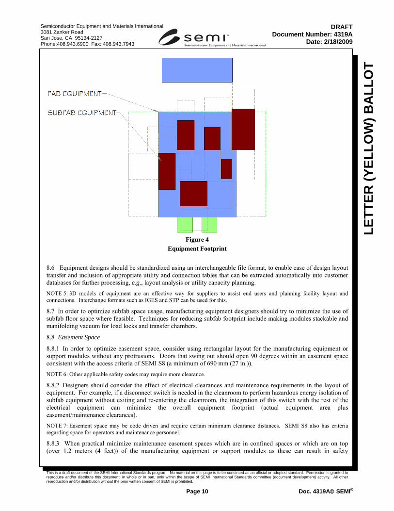
R1-2 Waste Neutralization Effect Scenario R1-2.1 New chemicals need to be added, to a piece of wet etch equipment to enable support of new technology requirements. Mechanical/Chemical Engineers add new supply lines for new chemicals. To save money and space all drains are combined into one (1) AWN connection. No mixing compatibility issue exists with the chemicals use in the piece of equipment. Ten (10) such pieces of equipment are expected to be shipped to a 300 mm fab. (See Figure R1-2.)
This is a draft document of the SEMI International Standards program. No material on this page is to be construed as an official or adopted standard. Permission is granted to reproduce and/or distribute this document, in whole or in part, only within the scope of SEMI International Standards committee (document development) activity. All other reproduction and/or distribution without the prior written consent of SEMI is prohibited.
Page 17 Doc. 4319A© SEMI®
Semiconductor Equipment and Materials International 3081 Zanker Road San Jose, CA 95134-2127 Phone:408.943.6900 Fax: 408.943.7943
LETT
ER (Y
ELLO
W) B
ALL
OT
DRAFTDocument Number: 4319A
Date: 2/18/2009
Figure R1-2
Waste Neutralization Effect Scenario
R1-3 Exhaust System Effect Scenario R1-3.1 New Single wafer process equipment planned. Current equipment requires 1200 scfm of scrubbed exhaust. Customer expected to purchase five times the number of pieces of equipment due to run rate reduction. Technology

This is a draft document of the SEMI International Standards program. No material on this page is to be construed as an official or adopted standard. Permission is granted to reproduce and/or distribute this document, in whole or in part, only within the scope of SEMI International Standards committee (document development) activity. All other reproduction and/or distribution without the prior written consent of SEMI is prohibited.
Page 18 Doc. 4319A© SEMI®
Semiconductor Equipment and Materials International 3081 Zanker Road San Jose, CA 95134-2127 Phone:408.943.6900 Fax: 408.943.7943
LETT
ER (Y
ELLO
W) B
ALL
OT
DRAFTDocument Number: 4319A
Date: 2/18/2009
requirements, piece of equipment cost, yield improvement and footprint seem to result in positive ROI for customer. Supplier Mechanical Design Engineer sees no reason to change exhaust requirements. (See Figure R1-3.)
Figure R1-3
Exhaust System Effect Scenario

This is a draft document of the SEMI International Standards program. No material on this page is to be construed as an official or adopted standard. Permission is granted to reproduce and/or distribute this document, in whole or in part, only within the scope of SEMI International Standards committee (document development) activity. All other reproduction and/or distribution without the prior written consent of SEMI is prohibited.
Page 19 Doc. 4319A© SEMI®
Semiconductor Equipment and Materials International 3081 Zanker Road San Jose, CA 95134-2127 Phone:408.943.6900 Fax: 408.943.7943
LETT
ER (Y
ELLO
W) B
ALL
OT
DRAFTDocument Number: 4319A
Date: 2/18/2009
R1-4 Electrical System Effect Scenario
R1-4.1 New process equipment planned has several advantages over previous piece of equipment. However, power increase resulted in process equipment AC current requirement going from 380A to 410A. It is expected that a typical 300mm fab would require 30 of these pieces of equipment. PE Electrical Design Engineer indicates no issues expected. (See Figure R1-4.)
Figure R1-4 Electrical Effect Scenario

This is a draft document of the SEMI International Standards program. No material on this page is to be construed as an official or adopted standard. Permission is granted to reproduce and/or distribute this document, in whole or in part, only within the scope of SEMI International Standards committee (document development) activity. All other reproduction and/or distribution without the prior written consent of SEMI is prohibited.
Page 20 Doc. 4319A© SEMI®
Semiconductor Equipment and Materials International 3081 Zanker Road San Jose, CA 95134-2127 Phone:408.943.6900 Fax: 408.943.7943
LETT
ER (Y
ELLO
W) B
ALL
OT
DRAFTDocument Number: 4319A
Date: 2/18/2009
R1-5 Manufacturing Equipment Installation Effect Scenario
R1-5.1 Existing wet etch piece of equipment has multiple utility connections (electrical, chemical, water, drains, exhaust etc.). Due to the complex nature of installation, the customer views prefabricating the connections as high risk. Installation of the facility connection begins after the piece of equipment docks. The supplier’s startup team arrives to discover that key utilities will take 4-6 weeks to complete. (See Figure R1-5.)
Figure R1-5 Manufacturing equipment Installation Effect Scenario

This is a draft document of the SEMI International Standards program. No material on this page is to be construed as an official or adopted standard. Permission is granted to reproduce and/or distribute this document, in whole or in part, only within the scope of SEMI International Standards committee (document development) activity. All other reproduction and/or distribution without the prior written consent of SEMI is prohibited.
Page 21 Doc. 4319A© SEMI®
Semiconductor Equipment and Materials International 3081 Zanker Road San Jose, CA 95134-2127 Phone:408.943.6900 Fax: 408.943.7943
LETT
ER (Y
ELLO
W) B
ALL
OT
DRAFTDocument Number: 4319A
Date: 2/18/2009
RELATED INFORMATION 2 UTILITY SUPPORT INFORMATION FOR TYPICAL MANUFACTURING EQUIPMENT SUPPORT SYSTEMS NOTICE: This related information is not an official part of SEMI Doc. 4319A and was derived from the work of the Task Force which developed this document. This related information was approved for publication by letter ballot on (date of approval).
R2-1 Manufacturing equipment Installation Effect R2-1.1 This section provides the equipment and process module designers some insight into the effect that can result when facility systems are not considered as part of the design information.
R2-1.2 The design of the manufacturing equipment has direct and indirect effects on the costs for installation and operation. (See Related Information 1, Figure R1-5.)
R2-1.3 Design Phase Effects —The effects on the facility and facility design are costly if data are not accurate and timely. Effects on installation and cost include:
R2-1.3.1 Delays in obtaining the required equipment data can decrease the time available to complete the design. This delay often results in the facility designer making conservative assumptions that lead to over design with the associated increased costs.
R2-1.3.2 Data provided by the manufacturing equipment suppliers are used to generate the installation design drawings. Design schedule and cost effects are incurred when data are missing, incorrect, or substantially different than originally provided when the certified manufacturing equipment drawings are received or the equipment is delivered. If data are missing, the facility design firm may prevent the designs from being released.
R2-1.3.3 Incorrect statements of manufacturing equipment requirements can lead to the design and construction of utilities services that do not meet the needs of the equipment.
R2-1.3.4 Overstated requirements can lead to oversized piping, ductwork, or cables which result in unnecessary costs, both in installation and operation.
R2-1.3.5 Understated requirements can lead to installation of too small piping, ductwork, or cables which will result in removal and reinstallation, which will result in unnecessary costs in installation.
R2-1.4 All pieces of support equipment (e.g., roughing pumps) needed by the manufacturing equipment for operation and all utilities required for the supporting equipment must be listed by the manufacturing equipment manufacturer to ensure proper equipment layout decisions. If all process modules or support equipments are not known, layout effects may mean that the manufacturing equipment may no longer fit in the planned space, requiring a possible new location, unplanned stacking of modules with associated maintenance difficulties, or the inability to install additional equipment.
R2-1.5 Use of adapter plates as an integral part of the installation will improve the installation process for the equipment and decrease installation time. An adapter plate or docking station is a three dimensional object that is designed by the equipment supplier, contains all equipment points of connection, and is shipped prior to the main manufacturing equipment. The final connections between the adapter plate and main equipment are performed by the equipment supplier as the main manufacturing equipment is installed. This allows for:
• a single point of connection to the facility, • internal equipment pressure regulation, • all facility work to be completed prior to receiving the main equipment, • shorter installation times, and • lower installation material costs.
This is a draft document of the SEMI International Standards program. No material on this page is to be construed as an official or adopted standard. Permission is granted to reproduce and/or distribute this document, in whole or in part, only within the scope of SEMI International Standards committee (document development) activity. All other reproduction and/or distribution without the prior written consent of SEMI is prohibited.
Page 22 Doc. 4319A© SEMI®
Semiconductor Equipment and Materials International 3081 Zanker Road San Jose, CA 95134-2127 Phone:408.943.6900 Fax: 408.943.7943
LETT
ER (Y
ELLO
W) B
ALL
OT
DRAFTDocument Number: 4319A
Date: 2/18/2009
R2-1.6 Standardize (See SEMI E76.) subfab and support modules. Support equipment that is shipped with facility interfaces enables quick and accurate equipment installation. The template concept can also be extended to the subfab to improve facility system interfacing.
R2-1.7 Construction Phase Effects — Facility utilities installed to support manufacturing equipment based on poor utility usage data may need to be removed and reworked to match the equipment requirements once it arrives. This causes increased schedule and layout costs associated with the demolition and reinstallation of the facility work. Facility systems that can be affected include:
• process utility piping (gases, chemical, UPW, PCW,CDA), • ductwork (exhaust, supply and return air), and • cables (electrical, process and facility controls).
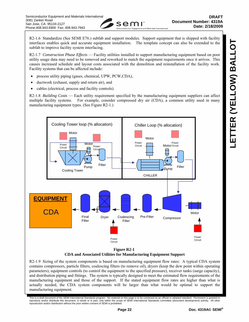
R2-1.8 Building Costs — Each utility requirement specified by the manufacturing equipment suppliers can affect multiple facility systems. For example, consider compressed dry air (CDA), a common utility used in many manufacturing equipment types. (See Figure R2-1.)
Figure R2-1 CDA and Associated Utilities for Manufacturing Equipment Support
R2-1.9 Sizing of the system components is based on manufacturing equipment flow rates: A typical CDA system contains compressors, particle filters, coalescing filters (to remove oil), dryers (keep the dew point within operating parameters), equipment controls (to control the equipment to the specified pressure), receiver tanks (surge capacity), and distribution piping and fittings. The system is typically designed to meet the estimated flow requirements of the manufacturing equipment and those of the support. If the stated equipment flow rates are higher than what is actually needed, the CDA system components will be larger than what would be optimal to support the manufacturing equipment.
FinalFilter
Coalescing Filter
Pre-Filter CompressorMotor
PowerCircuitPower
Circuit
PowerCircuit
PowerCircuit
PowerCircuit
Cooling Tower
Dryer
CHILLER
Motor
Motor
Pump Filter
MotorPowerCircuit
Pump
Motor
Filter
EQUIPMENT
CDA
Cooling Tower loop (% allocation) Chiller Loop (% allocation)

This is a draft document of the SEMI International Standards program. No material on this page is to be construed as an official or adopted standard. Permission is granted to reproduce and/or distribute this document, in whole or in part, only within the scope of SEMI International Standards committee (document development) activity. All other reproduction and/or distribution without the prior written consent of SEMI is prohibited.
Page 23 Doc. 4319A© SEMI®
Semiconductor Equipment and Materials International 3081 Zanker Road San Jose, CA 95134-2127 Phone:408.943.6900 Fax: 408.943.7943
LETT
ER (Y
ELLO
W) B
ALL
OT
DRAFTDocument Number: 4319A
Date: 2/18/2009
R2-1.10 Higher pressure requirements for manufacturing equipment can exceed the pressure capabilities of industry off the shelf compressors. Semiconductor manufacturers would then need to buy special, more expensive compressors and support components to provide the higher pressure, even if the number of manufacturing equipment units requiring the higher pressure were small. For example, do not exceed SEMI E51 pressure guidelines.
R2-1.11 CDA system components are sized to manufacturing equipment dewpoint requirements; the lower the dewpoint requirement for manufacturing equipment, the higher the load on the CDA dryer. Lower dewpoint increases the percentage of the compressor capacity that is used during the dryer purge cycles. Lower dew points may also require special, more expensive dryers.
R2-1.12 If CDA system components are sized to overstated manufacturing equipment flow requirements, the demand would require a combination of more and larger compressors, filters, and dryers. The receiver would also need to be sized larger as surge would be expected to be larger. This results in the need for a larger area for the CDA in the central utility plant.
R2-1.13 Manufacturing equipment CDA requirements can also have effects on other facilities systems:
R2-1.14 Chilled Water: Many CDA compressors are water cooled and thus are an added load on the chilled water system. The more CDA needed, the higher the chilled water load. Chilled Water Systems require water chillers, filters, pumps, motors, distribution piping and typically chemical treatment systems to inhibit corrosion and biological growth/fouling in the system. Conductivity requirements will require the use of RO makeup water instead of industrial water and possibly additional treatment.
R2-1.15 Cooling Towers (Condensing Water): Many chilled water systems eventually reject heat through cooling towers. The condensing water systems connected to the chillers of the chilled water system typically include the cooling towers, pumps, motors, mixed media filters, and chemical treatment.
R2-1.16 City water: Chilled water and condensing water systems will use city water make-up. Cooling towers will typically use more city water make-up because they need to have periodic water purge cycles as the evaporation cycle tends to raise water conductivity and propensity for scaling as mineral concentrations rise. The additional water evaporated from the cooling towers creates plumes or mists.
R2-1.17 Overstated gas and chemical requirements increase the number and size of the distribution assemblies in the subfab.
R2-1.18 Other Operating Costs
R2-1.19 Facility Systems: Power, Gas, Water, HVAC, UPW, WWTP, PV, Gases and Chemicals
R2-1.20 Operating Costs: Electrical, Water, Natural Gas, Bulk Gases, Chemicals
R2-1.21 Maintenance Costs: Preventive Maintenance, Emergency Repairs,
R2-1.22 Power to operate motors, operate controls, dampers, valves: Overstated manufacturing equipment requirements that lead to over designed power systems may not affect the actual power usage, but they will affect the initial capital costs of a facility and other operating costs such as preventative or predictive maintenance procedures (PMs).
R2-1.23 Overstated manufacturing equipment requirements that lead to over designed UPW systems may not affect the actual UPW usage, but they will affect the initial capital costs of a facility and other operating costs such as preventative or predictive maintenance procedures (PMs). Similarly an oversized waste water treatment plant (WWTP) will increase operation and maintenance costs

This is a draft document of the SEMI International Standards program. No material on this page is to be construed as an official or adopted standard. Permission is granted to reproduce and/or distribute this document, in whole or in part, only within the scope of SEMI International Standards committee (document development) activity. All other reproduction and/or distribution without the prior written consent of SEMI is prohibited.
Page 24 Doc. 4319A© SEMI®
Semiconductor Equipment and Materials International 3081 Zanker Road San Jose, CA 95134-2127 Phone:408.943.6900 Fax: 408.943.7943
LETT
ER (Y
ELLO
W) B
ALL
OT
DRAFTDocument Number: 4319A
Date: 2/18/2009
R2-2 Facility Utility System Information for Typical Manufacturing Equipment Support Systems
Table R2-1 Utility Support Requirements
Utility Equipment needed to provide utility to manufacturing equipment
Facility support systems used by utility
Clean Dry Air (CDA) compressors, motors, particle filters, coalescing filters, dryers, distribution piping, valves, fittings, structural support, controls
chilled water loop, condenser water loop, make-up water, power
Exhaust fans, motors, back-draft dampers, ducts, stacks, fittings, structural support, controls
make-up air handlers, chilled water loop, condenser water loop, hot water loop, power
Process Cooling Water (PCW) /Chilled PCW
pumps, motors, heat exchangers, filters, expansion tanks, distribution piping, valves, fittings, structural support, controls
chilled water loop, condenser water loop, make-up water, power
Vacuum vacuum pumps, motors, distribution piping, structural support, controls
chilled water loop, condenser water loop, power
NOTICE: SEMI makes no warranties or representations as to the suitability of the standard(s) set forth herein for any particular application. The determination of the suitability of the standard(s) is solely the responsibility of the user. Users are cautioned to refer to manufacturer’s instructions, product labels, product data sheets, and other relevant literature respecting any materials or equipment mentioned herein. These standards are subject to change without notice.
By publication of this standard, Semiconductor Equipment and Materials International (SEMI) takes no position respecting the validity of any patent rights or copyrights asserted in connection with any item mentioned in this standard. Users of this standard are expressly advised that determination of any such patent rights or copyrights, and the risk of infringement of such rights are entirely their own responsibility.