b1173_app5_1a
DESCRIPTION
nnTRANSCRIPT
FMG Port Layout Alternatives Pilbara Iron Ore and Infrastructure Project February 2005
Townley & Associates Pty Ltd i T&A0417-01 Rev1
Pilbara Iron Ore and Infrastructure Project
Evaluation of Port Layout Alternatives
prepared for
Fortescue Metals Group Limited ACN 57 002 594 872
Fortescue House 50 Kings Park Rd
West Perth WA 6005 Telephone: 08 9266 0111, Facsimile: 08 9266 0188
by
Townley & Associates Pty Ltd ACN 069 270 846
PO Box 3150, Nedlands WA 6909 Telephone: 08 9389 6377, Facsimile: 08 9389 6477
February 2005

FMG Port Layout Alternatives Pilbara Iron Ore and Infrastructure Project February 2005
Townley & Associates Pty Ltd ii T&A0417-01 Rev1
TABLE OF CONTENTS LIST OF FIGURES ................................................................................................................................. III
1 SUMMARY .................................................................................................................................... 4
2 INTRODUCTION ........................................................................................................................... 5 2.1 BACKGROUND ....................................................................................................................... 5 2.2 OBJECTIVES.......................................................................................................................... 5
3 REQUIREMENTS, ALTERNATIVES AND ISSUES ..................................................................... 6 3.1 PROJECT REQUIREMENTS...................................................................................................... 6 3.2 ALTERNATIVE LAYOUTS ......................................................................................................... 6 3.3 ISSUES.................................................................................................................................. 7
3.3.1 Access to land........................................................................................................... 7 3.3.2 Design criteria for rail and materials handling infrastructure..................................... 8 3.3.3 Minimum ground level ............................................................................................... 9 3.3.4 Dredging and filling.................................................................................................. 10 3.3.5 Geotechnical constraints......................................................................................... 11 3.3.6 Mangrove systems .................................................................................................. 12 3.3.7 Proximity to Wedgefield .......................................................................................... 13
4 ANALYSIS OF ALTERNATIVE LAYOUTS................................................................................. 14 4.1 COMPARISON OF ALTERNATIVES .......................................................................................... 14 4.2 IMPACTS ON MANGROVE SYSTEMS....................................................................................... 15 4.3 POSSIBLE FURTHER MODIFICATIONS OF THE PREFERRED LAYOUT ........................................ 16 4.4 CONCLUSION....................................................................................................................... 17
5 REFERENCES ............................................................................................................................ 21
6 ACKNOWLEDGEMENTS ........................................................................................................... 22
FIGURES ............................................................................................................................................... 23
APPENDIX............................................................................................................................................. 35

FMG Port Layout Alternatives Pilbara Iron Ore and Infrastructure Project February 2005
Townley & Associates Pty Ltd iii T&A0417-01 Rev1
LIST OF FIGURES
Figure 1 Early layout of port facilities to south of rail line (December 2003)........................................ 24
Figure 2 Original layout of port facilities to north of rail line (Figure 2.2 of DALSE, 2004)................... 25
Figure 3 Final layout of port (Figure 2 of FMG 2004)........................................................................... 26
Figure 4 Proposed port layout by Hope Downs (Figure 5.1 of Hope Downs 2002) ............................. 27
Figure 5 Schematic layout of developable land areas, according to PHPA (Figure 3-2 of Worley 2003)............................................................................................ 28
Figure 6 Possible linkages and reclamation areas, according to PHPA (Figure 4-4 of Worley 2003)............................................................................................ 29
Figure 7 Constraints on the port layout ................................................................................................ 30
Figure 8 Possible layouts of rail loop and FMG's preferred option ...................................................... 31
Figure 9 Relationship between FMG's proposal and PHPA plans (Figure 5 of FMG 2004) ................ 32
Figure 10 Mangrove systems at Anderson Point (Figure 13 of FMG 2004) ........................................ 33
Figure 11 Mangrove systems at Anderson Point (revised to achieve an ~8 ha reduction in impact on mangroves) .................................................................................................... 34

FMG Port Layout Alternatives Pilbara Iron Ore and Infrastructure Project February 2005
Townley & Associates Pty Ltd 4 T&A0417-01 Rev1
1 SUMMARY In its Public Environmental Review (PER) for Stage A of the Pilbara Iron Ore and Infrastructure Project, Fortescue Metals Group Limited (FMG) has proposed a layout for new port facilities at Anderson Point, Port Hedland.
The Department of Environment Marine Branch has requested further information demonstrating that efforts have been made to reduce potential impacts on mangrove systems.
This report presents and compares alternative layouts considered by FMG, prior to submission of the PER, and outlines measures taken to reduce impacts on mangroves.
In order to decide between options, FMG took into account land access issues (including relationships with BHPBIO's rail line, the proposed Hope Downs rail line and plans of the Port Hedland Port Authority), engineering issues (including the design of rail lines and conveyors), requirements for dredging and filling, geotechnical issues, the distribution of mangrove systems and proximity to Wedgefield (issues of noise and dust).
The preferred option includes reclaimed land with a footprint designed to minimise potential impacts on mangrove systems. Some impact is unavoidable, because of the need to manage dredge spoil effectively.
The proposed stockyards are located in the middle of the reclaimed land. The eastern part of the rail loop is also located on the reclaimed land.
The western and northern parts of the rail loop will require construction of an embankment and will have some affect mangrove systems, especially in the north. Tidal flow of water to mangrove systems inside the rail loop will be preserved.
The conveyor from the stockyards to the wharf facilities will be located on trestles, and will have little impact on mangrove systems below. The conveyor cannot be located further east as it would interfere with an access corridor designated in PHPA's plan.
Locating the rail loop and car dumper to the west of the stockyards will lead to the lowest possible noise impacts at Wedgefield, and will also ensure some flexibility in terms of possible future development by PHPA.
This report does not address issues related to the relative abundance of different mangrove systems in the region as this is covered within the Stage A PER and response to submissions. Its focus is on attempts made at a local scale to design the layout of the port infrastructure in the context of many potential constraints.
FMG's preferred layout, as presented in the PER, appears to be the best possible compromise between project requirements and other issues and constraints. Minor modifications may be possible during final design, but there appears to be no other feasible location for a rail loop that would have less impact on mangrove systems.

FMG Port Layout Alternatives Pilbara Iron Ore and Infrastructure Project February 2005
Townley & Associates Pty Ltd 5 T&A0417-01 Rev1
2 INTRODUCTION
2.1 Background
Fortescue Metals Group Limited (FMG) submitted a Public Environmental Review (PER) in September 2004 for Stage A of the Pilbara Iron Ore and Infrastructure Project, i.e. the Port and North-South Railway.
The port facilities include a rail loop, car dumper, stockyards, ore handling facilities, a screening facility, and a product conveyor to a wharf and shiploader at Anderson Point (see FMG 2004, p.viii).
Section 2.3 of the PER (esp. Section 2.3.2) explains that a number of alternative layouts were considered and evaluated.
Recent advice from the Department of Environment (DoE) Marine Branch1 indicated that more information is needed by DoE, specifically demonstrating that efforts have been made to reduce potential impacts on mangrove systems.
Townley & Associates Pty Ltd was commissioned by FMG to prepare an independent assessment of the layout of the port facilities, in parallel with other assessments by environmental scientists with special expertise in the distribution and ecology of mangrove systems.
2.2 Objectives
The purpose of this report is to document and discuss alternative layouts of port infrastructure, some of which were developed with the specific goal of seeking of avoiding and/or reducing potential impacts on mangrove systems.
In particular, Townley & Associates Pty Ltd was asked to document:
• What modifications to the port layout took place prior to submission of the PER, and why?
• What further modifications may or may not be possible, and why or why not?
1 See e-mail from Ian LeProvost, URS Corporation, to Laura Todd, FMG, being minutes of a meeting held with EPA Marine Branch on 26 October 2004.

FMG Port Layout Alternatives Pilbara Iron Ore and Infrastructure Project February 2005
Townley & Associates Pty Ltd 6 T&A0417-01 Rev1
3 REQUIREMENTS, ALTERNATIVES AND ISSUES
3.1 Project Requirements
The fundamental requirement for the port facilities (FMG 2004, p.19) is that there be sufficient infrastructure to allow export of 45 Mtpa of iron ore.
Within the port area, there is a need for a rail loop, twin cell rail dumper, 2.5 Mt of storage in stockyards, 2 x stackers (8,000 tph each) and a reclaimer (10,000 tph).
Required port facilities include a single wharf 750 m long, incorporating a parking berth, allowing 2 x 250,000 DWT vessels to be in port simultaneously.
Construction of the port facilities will require dredging from and filling to approved locations. Current estimates suggest a need for dredging of 3.3 million m3 and approximately 300 ha of reclaimed land for appropriate handling of fill.
3.2 Alternative Layouts
A number of significantly different layouts were considered prior to submission of the PER.
The options include:
• A rail loop to the south of BHP Billiton Iron Ore's (BHPBIO) rail line and Hope Downs' proposed rail line, with stockyards immediately to the north of the rail line(s), and a long conveyor to wharf facilities at Anderson Point (Figure 1).
• Stockyards to the north of the rail line(s), with a rail loop to the east (Figure 1).
• Stockyards to the north of the rail line(s), with a rail loop surrounding the stockyards (Figure 1).
• Stockyards to the north of the rail line(s), with a rail loop to the west, and provision for expansion of stockyards in relatively rectangular areas of reclaimed land (Figure 2).
• Stockyards to the north of the rail line(s), with a rail loop to the west, with stockyards further to the north and land reclamation designed to reduce potential impacts on mangrove systems (Figure 3).
Within the last option, the detailed layout has been modified in various ways to fine tune the areas of disturbance.

FMG Port Layout Alternatives Pilbara Iron Ore and Infrastructure Project February 2005
Townley & Associates Pty Ltd 7 T&A0417-01 Rev1
The PER describes the last option, which FMG believes to be the best option, given all known issues and constraints.
To support this assessment of alternative layouts, FMG commissioned Worley Pty Ltd to prepare two additional layouts to the south of Anderson Point. Townley & Associates Pty Ltd has also prepared numerous possible layouts that meet the geometric constraints of a rail loop and twin cell rail dumper. These options will be discussed below.
3.3 Issues
Numerous issues influence the acceptability of different options.
These include:
• Access to land, including the availability of an area sufficiently large to allow construction of a rail loop, consistency with regional plans and the existence of other infrastructure that cannot be relocated.
• Engineering requirements that limit the geometry of rail and materials handling infrastructure.
• Engineering requirements for the ground level to be raised above the storm surge level of 6.5 mAHD, i.e. 0.5 m higher than the level of the BHPBIO rail line.
• Engineering requirements relating to handling of dredge spoil and its use as landfill.
• Geotechnical constraints.
• The spatial distribution of mangrove systems, and other vegetation communities.
• Proximity to local residential areas, especially Wedgefield to the east, mainly from the point of view of potential impacts of noise and dust.
Each of these will be described here in more detail.
3.3.1 Access to land
There are numerous issues relating to land, including:
• The existing rail line operated by BHPBIO.
• The proposed Hope Downs' rail line.
• An existing signal box and wagon maintenance yards operated by BHPBIO, immediately to the east of FMG's proposed crossing of BHPBIO's rail line.

FMG Port Layout Alternatives Pilbara Iron Ore and Infrastructure Project February 2005
Townley & Associates Pty Ltd 8 T&A0417-01 Rev1
• The proposed crossing of Hope Downs' and BHPBIO's rail lines, near South West Creek.
• The layout of a Hope Downs' proposed rail line and marshalling yards to the south of BHPBIO's rail line (see Figure 4).
• The Port Hedland Port Authority's development plan (Worley 2003), which identifies a number of potentially developable areas near the inner harbour (see Figure 5). Areas A and B in Figures 5 and 6 have been identified as being suitable for use for port-related activities such as the iron ore industry and close to a possible deep water wharf at Anderson Point.
• PHPA's proposed corridor between Areas A and B, linking the Boodarie industrial area to the south with Point Anderson. This is shown in Figure 5 as a "possible corridor" and elsewhere (e.g. Figure 6) as corridor 150 m wide (see Worley 2003, Section 4.5).
• The location and hydrological behaviour of South West Creek, including the potential for cross flows towards Wedgefield following heavy rainfall.
3.3.2 Design criteria for rail and materials handling infrastructure
For heavy haul railway lines, a design constraint is the maximum grade for loaded trains, which is 0.33% or 0.175°. A bridge over or a tunnel under any railway line in the vicinity of the port are impractical2. An "at grade" crossing is the only practical option.
In order to unload 45 Mtpa, it is essential to operate a rail loop, with a twin cell rail dumper, rather than a straight line configuration as proposed by Hope Downs. A rail loop allows greater throughput and leads to significantly less noise due to shunting.
A rail loop has a number of geometric constraints:
• Minimum 2.8 km of track before the dumper, so that a whole train can wait to enter the dumper.
• Minimum 2.8 km of track after the dumper, so that all but the last 2 cars of a train can wait after the dumper.
• Minimum 1,000 m radius curves when full, to reduce wheel squeal.
2 A bridge would need to rise to about 10 m above local ground level. To rise 10 m at a slope of 0.33% would require an embankment rising 10 m over 3 km to the south of the BHPBIO line. This would require a very large borrow source (leading to significant disturbance), have unacceptable visual impacts and be prohibitively expensive. A loaded train could travel 10 m downwards at a steeper slope, in less than 1 km, but this would interfere with the rail loop, which needs to be flat for operational reasons. A similar argument explains why a tunnel would not be feasible, as it would require a 1 km descent and a 3 km rise within the rail loop area, in each case underground.

FMG Port Layout Alternatives Pilbara Iron Ore and Infrastructure Project February 2005
Townley & Associates Pty Ltd 9 T&A0417-01 Rev1
• Minimum 650 m radius curves when empty, to reduce wheel squeal.
• Minimum straight sections before and after the dumper to reduce wagon indexer loads (nominally 400 m and 100 m, pending advice during final design from the vendor of the dumper).
The optimum location for stockyards would be as close as possible to the shiploaders, to facilitate ship trimming3.
A general principle in materials handling, and in particular for iron ore, is to reduce disturbance ("lump product degradation") by reducing handling of materials. A premium price is commanded by larger lumps of iron ore, as distinct from fine particulates. For this reason, it is desirable to have straight or gently curved conveyors (as proposed) rather than multiple conveyors in series, thereby eliminating transfers.
Key requirements for locating the wharf include meeting PHPA's long term requirements, and taking into account tidal currents for manoeuvring ships and allowing ships alongside.
3.3.3 Minimum ground level
In order to ensure continuous operations of the port facilities, it is necessary to raise the ground level in areas where port infrastructure is proposed to at least 6.5 m AHD, i.e. above storm surge level. This level is based at least partly on PHPA requirements.
This could be achieved by taking suitable fill material from nearby borrow areas, or by using dredge spoil as fill. By proposing to use dredge spoil (see Section 3.3.4), FMG will avoid potential impacts of other kinds, such as terrestrial impacts at borrow areas, and marine impacts of submarine disposal of dredge spoil in other disposal areas.
3 FMG would prefer shorter conveyors to those already proposed. However, FMG has proposed a conveyor as in the PER to minimise impacts on mangroves, by having the stockpiles and reclamation area out of the mangroves, some distance from the ship loader. The proposed conveyor is already considered long for ship loading. The difficulty is one of ship loading control. An operator loading and trimming a ship gives an instruction for gaps in loading to occur, i.e. the belt has empty sections equal to the time it takes to move hatches or trimming load to put into a particular hold. If for whatever reason a stoppage occurs, then problems arise, the longer the conveyor the larger the operational and safety issues. There are safety issues associated with longer conveyors, as well as issues involving cost, materials handling, noise and dust. The safety issues are due to the large volume of material on the conveyor at any one time, hence the conveyor can be more difficult to manage during an emergency. A longer conveyor carries more material, has more momentum and is more difficult to stop quickly in an emergency. If the conveyor were any longer, consideration would have to be given to storing the excess material on the conveyor in surge bins on the wharf. These surge bins would be large structures with significant visual impacts.

FMG Port Layout Alternatives Pilbara Iron Ore and Infrastructure Project February 2005
Townley & Associates Pty Ltd 10 T&A0417-01 Rev1
3.3.4 Dredging and filling
Dredging will be required to allow construction of new wharf (to create a turning circle of sufficient depth for vessels), and it is therefore essential to find suitable locations for placement of dredge spoil. Dredge spoil should be handled so as to maximise its utilisation for current and future developments. At the same time, the potential impacts of the development on movement of water must be taken into account: this includes tidal flows (as modelled extensively by Worley, 2004) and storm surge.
Approximately 3.3 million m3 of material will be dredged from the Anderson Point area and used for onshore reclamation over a period lasting up to 12 months (Coffey Geosciences Pty Ltd, 2004, Section 4.3.3).
Dredging of 3.3 million m3 typically requires management of many times that volume of material, because of entrainment of seawater during dredging. This is the primary reason for needing to disturb/reclaim approximately 300 ha of land in the areas shown in Figure 3. The 300 ha will be need to ensure that dredge spoil settles and drains within the construction period.
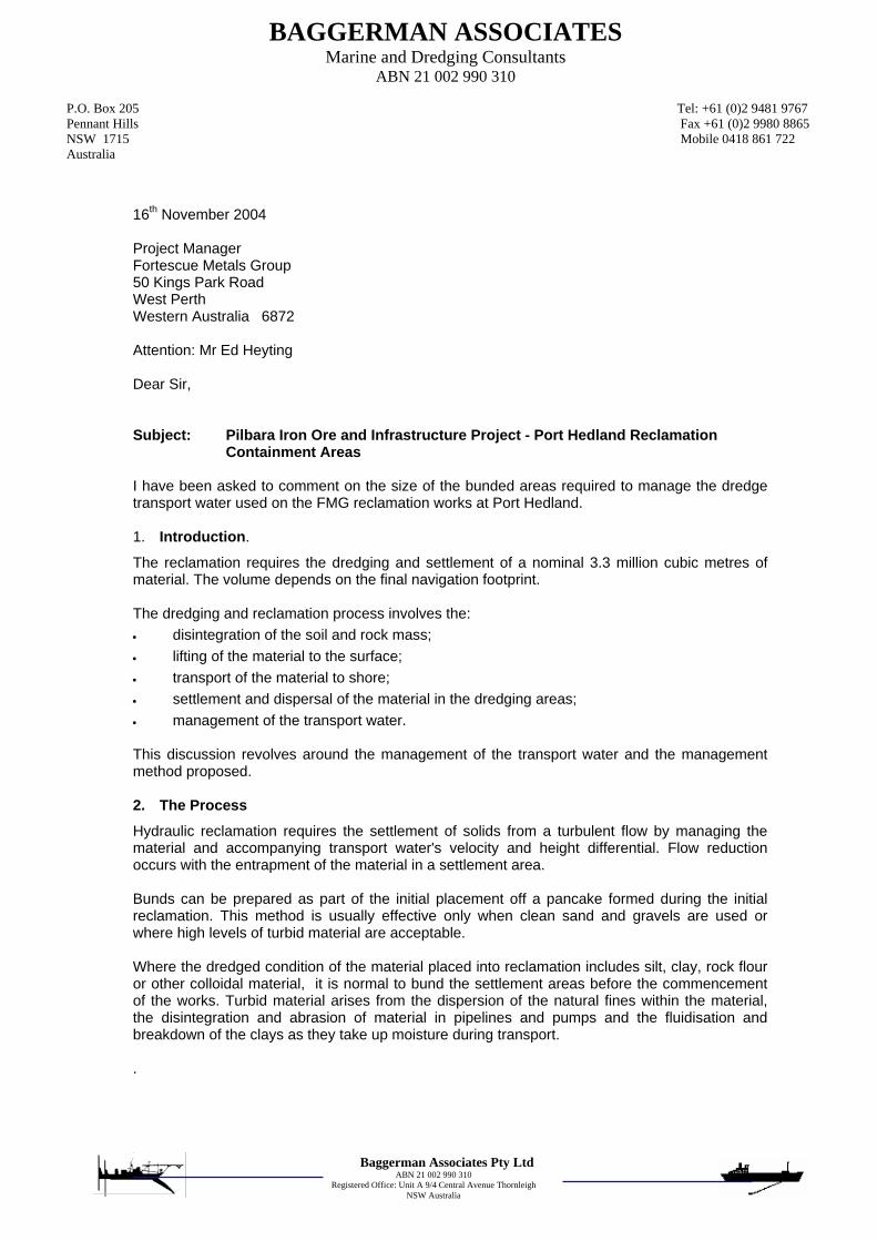
To explain and support this need, FMG asked Baggerman Associates Pty Ltd, marine and dredging consultants, to explain the proposed dredging and filling operations, in the context of their experience. Baggerman Associates have been working at Port Hedland since 1968. Their letter is included as an Appendix to this report. They argue that an area larger than 300 ha could be utilised if it were available, but that given the 300 ha, "a competent contractor with a well managed site will be able to undertake the works without undue impact on Port Hedland Harbour outside the footprint of the dredging works".
Within the reclamation areas, dredge material will be retained to settle the solids and decant the free water back into the port via sediment interception basins to reduce sediment load and turbidity (DALSE, 2004, Section 4.3.3). This water will be discharged to the port at locations and in a manner established in a Dredging and Reclamation Environmental Management Plan (DREMP) such that the potential for impact on the mangrove systems is as low as possible.
The return water discharge and route to the harbour will be designed so as not to cause damage to mangrove systems though erosion of creek beds and/or banks (DALSE, 2004, Section 4.3.3). Upon completion of the dredging, the spoil deposition areas will be drained and levelled. The finished surface will be seeded to reduce the potential for surface erosion from rainfall and dust generation. The perimeter bund will also contain internal stormwater runoff, which will be harvested and used for dust control. Excess surface runoff water will be treated via an oil separator and a sediment interceptor basin, prior to discharging to the environment.
In their desktop investigation, Coffey Geosciences Pty Ltd (2004) found that there were no materials in the proposed dredge area that would be unsuitable for reclamation. However, because this was only a preliminary

FMG Port Layout Alternatives Pilbara Iron Ore and Infrastructure Project February 2005
Townley & Associates Pty Ltd 11 T&A0417-01 Rev1
survey, FMG held discussions with PHPA and reached agreement that should more detailed investigations find large quantities of unsuitable material, it may be disposed of at the PHPA spoil grounds, subject to meeting the regulatory requirements for disposal at sea. Ongoing geotechnical investigations have revealed that the need for sea disposal is unlikely.
3.3.5 Geotechnical constraints
Appropriate sites for infrastructure (rail lines, dumper, stockyards and wharf) are influenced by geotechnical conditions. Poor geotechnical conditions can make it difficult for infrastructure to be constructed in those locations, (because a stable foundation is required before construction can start). As a result, it is much more practical to construct heavily loaded infrastructure in locations with better subsurface conditions.
Coffey Geosciences Pty Ltd (2004, Section 8.6) have provided preliminary advice on geotechnical conditions near the proposed port facilities, particularly in relation to suitability for reclamation:
• The area close to Anderson Point is suitable for dredged fill reclamation provided it does not extend into the mangrove zone surrounding this area where mangrove mud up to nominally 3.5 m could prove difficult to construct starter embankments on (low strength and long consolidation periods). Due to the presence of weak surficial sands, silts and clays/muds across the area, which extend to depths of around 2.5 m, the consolidation time throughout this area may vary considerably, albeit significantly shorter than any filling on mangrove mud.
• The area of the proposed stockyards is also suitable for dredged fill reclamation, particularly in the southernmost areas and areas devoid of mangroves and accompanying thick low strength mud. Hand probing indicated that the strength of the surficial soils improved significantly in the southernmost areas, with increasing distance from the mangrove zones. There is a zone to the east of the proposed stockyards (see hand probe HP49 in Coffey Geosciences Pty Ltd, 2004), between the stockyards and PHPA's "possible corridor", where up to 2.4 m of weaker materials have been found. This is the primary reason why FMG has chosen to locate stockyards in the preferred location. It is believed that the area to the immediate east may be suitable in the longer term, but the ground will need to be surcharged to enhance consolidation rates, prior to construction of heavy facilities in this area.
• Mangroves are thickest in areas immediately surrounding creeks. If starter embankments are to be constructed in mangrove areas, the mangroves within the embankment footprints need to be cut at ground level and laid horizontally to retain the root zone and provide additional base reinforcement and drainage. Additional reinforcement in the form of geosynthetics may be needed to support the construction equipment and starter embankment.
FMG Port Layout Alternatives Pilbara Iron Ore and Infrastructure Project February 2005
Townley & Associates Pty Ltd 12 T&A0417-01 Rev1
3.3.6 Mangrove systems
The primary motivation for preparation of this report was to demonstrate that the location of mangrove systems was taken into account during consideration of alternative possible layouts of port infrastructure, and furthermore that efforts were made to avoid mangrove, and otherwise to reduce potential impacts.
Biota Environmental Science Pty Ltd (2004) surveyed the vegetation in the area of the port. Of particular importance is the fact that they identified a number of areas which do not include mangrove species. These include:
• supratidal areas (mixed salt-tolerant shrubs and grasses on lower elevations),
• bare sand and mud, and
• algal mats.
Some of the mangrove assemblages, while mapped as such, are known to be essentially bare.
Section 7.3.4 of the PER (FMG, 2004) is devoted to potential impacts on mangrove systems, and management of those potential impacts. In discussing Principle 1 of EPA Guidance Statement No.29 on Benthic Primary Producer Habitats (BPPH), FMG (2004, p.160) explained that several options had been considered for the location and configuration of port facilities, and stated that the preferred option avoids loss of mangrove systems "as far as possible within the engineering design, land use and other constraints applying to the port facility".
Briefly the following were considered:
• Situation and alignment of the stockpile area, to minimise disturbance;
• Modelling to aid in the design of structures to ensure adequate hydrodynamic exchange;
• Modification of dredge spoil bund to minimise disturbance;
• All necessary clearing to be clearly pegged and flagged in the field;
• Design of surface drainage to include best practice management;
• Best practice dust suppression technology to be adopted;
• Preparation of a mangrove and littoral vegetation rehabilitation plan and monitoring program; and
• Funding for research.

FMG Port Layout Alternatives Pilbara Iron Ore and Infrastructure Project February 2005
Townley & Associates Pty Ltd 13 T&A0417-01 Rev1
3.3.7 Proximity to Wedgefield
The proximity of Wedgefield was recognised by Worley (2003) as a potential limit on the Ultimate Development Plan (UDP) for the port.
Appendices F and G of the PER (FMG, 2004) address issues of dust and noise, respectively.
During preparation of this report, Lloyd Acoustics were asked to analyse the noise impacts of a rail loop to the south of Anderson Point. No formal report has been prepared, but the resultant LAeq (8 hour) level in Wedgefield was found to be about 46 dB(A), i.e. about 3 dB(A) higher than the original loop (Daniel Lloyd, pers.comm., 18 November 2004). Maximum levels are likely to be increased by 5 dB(A).
Any layout even further to the east would probably lead to LAeq (8 hour) closer to 50 dB(A).
These issues lead to a preference for locating the rail loop as far from Wedgefield as possible.

FMG Port Layout Alternatives Pilbara Iron Ore and Infrastructure Project February 2005
Townley & Associates Pty Ltd 14 T&A0417-01 Rev1
4 ANALYSIS OF ALTERNATIVE LAYOUTS
4.1 Comparison of Alternatives
Given the requirements of the project (Section 3.1) and the issues that affect the layout of infrastructure (Section 3.3), FMG has considered and assessed many alternative layouts, i.e. those identified in Section 3.2 and more.
Figure 7 shows an overlay of the major constraints to the location of rail facilities: BHPBIO's existing rail line, Hope Downs' proposed line, marshalling yards, borrow areas etc., Hope Downs' corridor through its State Agreement Act (known as FNA 1545), PHPA's development plan and the town of Wedgefield.
Figure 8 shows a number of rail loops that meet the geometric constraints for a rail loop, but for various reasons explained below are less satisfactory than the preferred layout. Corresponding stockyards are not shown. Stockyards outside the loop are preferable from the point of view of safety. A north-south orientation east of the rail loop is best from the point of view of reducing noise levels in Wedgefield.
The rail loops can be grouped in four groups:
• Rail track 8 to the south of the BHPBIO line conflicts with Hope Downs' rail infrastructure.
• Rail tracks 6 and 7 close to Wedgefield (of which one crosses the BHPBIO line at the reverse angle) are too close to Wedgefield, from points of view of noise and dust.
• Rail tracks 2 to 5 directly to the south of Anderson Point would have more impact on Wedgefield than those further to the west, but the primary disadvantage of these loops is that they cross PHPA's possible corridor to Anderson Point, and either alienate or inconvenience the majority of PHPA's areas A and B. Some of these options may also have greater impacts on flow in South West Creek.
• Rail track 1 and FMG's preferred option to the west, overlapping Hope Downs' proposed borrow area4, are the best options from the point of view of noise and dust, as well as from the point of view of creating the best opportunities for long term use of Anderson Point by FMG, other users of FMG's infrastructure and even third parties. Rail track 1 would reduce impacts on mangroves but intersects Hope Downs' proposed stockyard area.
4 FMG have offered to provide an alternative source of borrow for Hope Downs.

FMG Port Layout Alternatives Pilbara Iron Ore and Infrastructure Project February 2005
Townley & Associates Pty Ltd 15 T&A0417-01 Rev1
One option not explicitly shown in any Figures is that of a rail spur to and from the port, i.e. without a loop. Such an option would not suit FMG's needs, or its obligations under the recently passed Railway and Port (The Pilbara Infrastructure Pty Ltd) Agreement Act 2004 to be an open access infrastructure provider assisting other companies in the export of resources. A rail loop will ensure greater potential throughput. A rail spur would require two dumpers, and would add a requirement for splitting trains and increased noise levels due to shunting.
An analysis is provided of the five alternatives considered prior to the PER, as listed in Section 2.3. The results of the analysis are presented in Table 1.
FMG's preferred layout is overlaid on PHPA's development plan in Figure 9. FMG proposes a much smaller wharf area at Anderson Point, and will not require reclaiming as much land in PHPA's Areas A and B. However FMG proposes to extend the reclaimed area further to the north, in order to allow for stockyards to be closer to the wharf (see explanation in Section 3.3.2), and also to allow more flexibility in the future.
4.2 Impacts on Mangrove Systems
No attempt is made in this report to place the impacts on mangrove systems in a regional context, as this is covered in the Stage A PER and response to submissions. The focus of this report is local, i.e. on alternative layouts of port facilities in the context of local issues and potential constraints.
The vegetation communities (mangrove systems) near Anderson Point are shown in Figure 13 of FMG's PER (2004), reproduced here as Figure 10. That Figure has been revised and updated by Biota Environmental Science Pty Ltd (Garth Humphreys, pers.comm., 8 December 2004) and the revised Figure is provided here as Figure 11. Revised outlines of areas proposed for port infrastructure are shown in blue. The areas have been modified based on more accurate mapping of mangrove communities (to avoid further mangroves), but also to take account of a number of known cultural heritage sites.
The largest area to be affected by the proposed port facilities is the area of reclaimed land, containing the proposed stockyards and the eastern arm of the rail loop. This irregularly shaped area has four main vegetation communities, of which only one (the smallest) is a mangrove assemblage:
• Supratidal areas (mixed salt-tolerant shrubs and grasses on lower elevations): south of the proposed stockyards, and also 1 km to the southeast, in areas of higher elevation.
• Bare sand and mud: generally surrounding the supratidal areas.
• Algal mats: a relatively large area under the middle of the proposed stockyards, and extending 200-500 m further east.

FMG Port Layout Alternatives Pilbara Iron Ore and Infrastructure Project February 2005
Townley & Associates Pty Ltd 16 T&A0417-01 Rev1
• Avicennia marina and/or mixed samphires: areas to the north, east and southeast of the proposed stockyards.
These areas are shown in mustard, white, grey and pale yellow in Figure 11, respectively.
The impact of proposed infrastructure on mangrove assemblages has been re-analysed by Biota Environmental Science Pty Ltd (Garth Humphreys, pers.comm., 8 December 2004). The results are shown in Table 2. Six different zones within the port area have been considered, as defined below the Table. The vegetation communities and/or mangrove assemblages are as defined in the legend of Figure 11 and shown in Table 2.
The total area affected is ~329 ha, of which ~278 ha are in the main land reclamation area, ~18 ha are in the Anderson Point reclamation area, ~28 ha are associated with the rail loop and ~6 ha are under conveyors and roads. The total area of mangrove assemblages affected by the proposed infrastructure is less than 15 ha, primarily in mangrove assemblages 2, 3 and 4A. Of the 15 ha, nearly 2 ha are under conveyors, in other words the impact will be less than complete. A reduction of approximately 8 ha has been achieved since the Stage A PER was prepared and submitted.
The size of the area of reclaimed land is dictated by the need to handle an estimated 3.3 million m3 of dredge spoil.
While the rail line needs to be constructed on an embankment, the conveyors between the car dumper and the stockyards, and between the stockyards and the wharf will be via trestle bridges.
4.3 Possible Further Modifications of the Preferred Layout
Given the option of constructing a wharf at Anderson Point, FMG has sought to find locations for port infrastructure (including a rail loop and stockyards) that meet engineering requirements in the context of other issues and constraints.
There remain possibilities for minor changes in the preferred designs, but these will depend on the results of investigations during final design (such as geotechnical investigations, and investigations related to dredging and filling) and on decisions made by other organisations, such as Hope Downs and PHPA. FMG will continue to discuss options with these and other stakeholders during final design.
It is unlikely that there exist possible layouts that are significantly different from those currently considered. The geometrical requirements for a rail loop, the angle at which rail lines must cross, and the requirement for 300 ha for management of dredge spoil limit the number of options.

FMG Port Layout Alternatives Pilbara Iron Ore and Infrastructure Project February 2005
Townley & Associates Pty Ltd 17 T&A0417-01 Rev1
4.4 Conclusion
FMG's preferred layout meets engineering and operational requirements and is the best compromise between constraints and desires for lesser impacts of different kinds. The overall impact on mangrove communities is less than 15 ha.
FMG's State Agreement Act requires FMG to maintain a policy of "open access" to its infrastructure. PHPA has prepared a development plan for the port of Port Hedland, and FMG's preferred layout is generally consistent with that plan and meets its obligations under the Railway and Port (The Pilbara Infrastructure Pty Ltd) Agreement Act 2004. The preferred layout will provide greater opportunities for access to the port than other layouts.

FMG Port Layout Alternatives Pilbara Iron Ore and Infrastructure Project February 2005
Townley & Associates Pty Ltd 18 T&A0417-01 Rev1
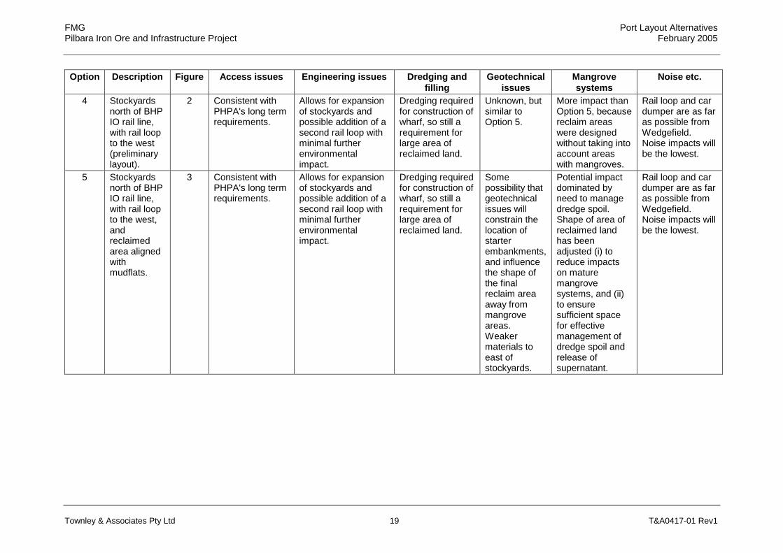
Table 1 Analysis of alternative layouts
Option Description Figure Access issues Engineering issues Dredging and filling
Geotechnical issues
Mangrove systems
Noise etc.
1 A rail loop south of BHP IO rail line, with stockyards just north of the line.
1 Interferes with PHPA's proposed Boodarie Support Industry Area, access corridor and buffer zone.
Not possible, due to space constraints imposed by the Hope Downs alignment and the location of their proposed railway workshops and yard, in the Boodarie area. Stockyards too far from proposed wharf, from materials handling point of view.
Dredging required for construction of wharf, so still a requirement for large area of reclaimed land.
Details not known, as this Option was not pursued.
Possibly lowest impact on mangrove systems, but still need to find a place to place dredge spoil.
Rail loop and car dumper are close to Wedgefield, hence greatest potential noise impacts.
2 Stockyards north of BHP IO rail line, with rail loop to the east.
1 Interferes with PHPA's proposed Boodarie Support Industry Area, access corridor and buffer zone.
Not possible, due to space constraints imposed by the Hope Downs alignment and the location of their proposed railway workshops and yard, in the Boodarie area.
Dredging required for construction of wharf, so still a requirement for large area of reclaimed land.
Details not known, as this Option was not pursued.
Potential impact on mangrove systems closer to Wedgefield.
Rail loop and car dumper are closest to Wedgefield, hence greatest potential noise impacts.
3 Stockyards north of BHP IO rail line, with rail loop around the stockyards.
1 Limits expansion and "open access" options, particularly additional stockyard capacity.
Introduces safety issues associated with access to the centre or the loop, with more personnel crossing the railway line.
Dredging required for construction of wharf, so still a requirement for large area of reclaimed land.
Details not known, as this Option was not pursued.
Similar impacts to Options 4 and 5.
Rail loop and car dumper are relatively close to Wedgefield. Less noise than in Options 1 or 2.
FMG Port Layout Alternatives Pilbara Iron Ore and Infrastructure Project February 2005
Townley & Associates Pty Ltd 19 T&A0417-01 Rev1
Option Description Figure Access issues Engineering issues Dredging and filling
Geotechnical issues
Mangrove systems
Noise etc.
4 Stockyards north of BHP IO rail line, with rail loop to the west (preliminary layout).
2 Consistent with PHPA's long term requirements.
Allows for expansion of stockyards and possible addition of a second rail loop with minimal further environmental impact.
Dredging required for construction of wharf, so still a requirement for large area of reclaimed land.
Unknown, but similar to Option 5.
More impact than Option 5, because reclaim areas were designed without taking into account areas with mangroves.
Rail loop and car dumper are as far as possible from Wedgefield. Noise impacts will be the lowest.
5 Stockyards north of BHP IO rail line, with rail loop to the west, and reclaimed area aligned with mudflats.
3 Consistent with PHPA's long term requirements.
Allows for expansion of stockyards and possible addition of a second rail loop with minimal further environmental impact.
Dredging required for construction of wharf, so still a requirement for large area of reclaimed land.
Some possibility that geotechnical issues will constrain the location of starter embankments, and influence the shape of the final reclaim area away from mangrove areas. Weaker materials to east of stockyards.
Potential impact dominated by need to manage dredge spoil. Shape of area of reclaimed land has been adjusted (i) to reduce impacts on mature mangrove systems, and (ii) to ensure sufficient space for effective management of dredge spoil and release of supernatant.
Rail loop and car dumper are as far as possible from Wedgefield. Noise impacts will be the lowest.

FMG Port Layout Alternatives Pilbara Iron Ore and Infrastructure Project February 2005
Townley & Associates Pty Ltd 20 T&A0417-01 Rev1
Table 2 Impact of proposed port infrastructure on mangrove assemblages
Classification Zone of impact (ha) Paling et al. Biota 1* 2* 3* 4* 5* 6* Total
1 1 0.00 0.00 0.00 0.01 0.11 0.00 0.12
2 2 0.64 0.00 1.02 3.52 0.00 0.00 5.18
3 3 2.39 0.00 0.61 1.97 0.08 0.04 5.09
4 4 0.00 0.00 0.00 0.00 0.04 0.00 0.04
4A 5 3.50 0.00 0.00 0.68 0.00 0.18 4.36
4B 6 82.47 0.00 0.00 10.17 0.66 1.14 94.44
7 0.00 0.00 0.00 0.00 0.00 0.00 0.00
8 0.00 0.00 0.00 0.00 0.00 0.00 0.00
8 9 0.00 0.00 0.00 0.00 0.01 0.00 0.01
Algal mats 50.12 0.00 0.00 0.00 0.16 0.00 50.28
Bare sand/mud 40.47 11.46 0.12 0.90 0.36 0.13 53.44
Water 0.25 0.00 0.18 0.82 0.00 0.00 1.25
Supratidal land 98.03 6.33 0.01 9.89 0.38 0.00 114.64
Total areas 277.87 17.79 1.94 27.96 1.80 1.49 328.85
Mangrove systems 6.53 0.00 1.63 6.18 0.24 0.22 14.80
Zones: 1. Main land reclamation area (and other infrastructure within this area, including stockyards and the eastern part of the rail loop).
2. Anderson Point reclamation area. 3. Conveyor from the stockpile to the wharf (excluding the Anderson Point
basin). 4. Rail loop (excluding parts of the line within the main land reclamation area). 5. Conveyor from car dumper to the edge of the reclamation area. 6. Access road to Anderson Point.

FMG Port Layout Alternatives Pilbara Iron Ore and Infrastructure Project February 2005
Townley & Associates Pty Ltd 21 T&A0417-01 Rev1
5 REFERENCES
Biota Environmental Science Pty Ltd (2004), Vegetation and Flora Survey of the Proposed FMG Stage A Rail Corridor, Fortescue Metals Group, Baseline Botanical Survey, August. (Appendix H to FMG's PER).
Coffey Geoscience Pty Ltd (2004), Pilbara Iron Ore and Infrastructure Project, Geotechnical Desktop Study and Site Visits, June. (Appendix N to FMG's PER).
DAL Science & Engineering Pty Ltd (2004), Pilbara Iron Ore and Infrastructure Project, Marine Environmental Impacts and their Management, July. (Appendix J to FMG's PER).
Fortescue Metals Group Limited (2004), Pilbara Iron Ore and Infrastructure Project, Stage A, Port and North-South Railway, Public Environmental Review, September.
Hope Downs (2002), Hope Downs Iron Ore Project, Rail and Port, Public Environmental Review, February.
Worley (2003), Port Hedland Port Authority, Planning Study, Phase 2, August.
Worley (2004), Port Hedland Harbour, Hydrodynamic Modelling of FMG Conceptual Layouts, May. (Appendix K to FMG's PER).

FMG Port Layout Alternatives Pilbara Iron Ore and Infrastructure Project February 2005
Townley & Associates Pty Ltd 22 T&A0417-01 Rev1
6 ACKNOWLEDGEMENTS
This report has been prepared based on discussions with and documentation provided by Laura Todd, Ed Heyting and Nicky Hogarth of FMG.
Discussions with Vince Piper of Aquaterra Consulting Pty Ltd and Garth Humphreys of Biota Environmental Science Pty Ltd are also gratefully acknowledged.
Daniel Lloyd of Lloyd Acoustics provided informal advice on the higher noise levels that would arise from one alternative layout.

FMG Port Layout Alternatives Pilbara Iron Ore and Infrastructure Project February 2005
Townley & Associates Pty Ltd 23 T&A0417-01 Rev1
FIGURES

FMG Port Layout Alternatives Pilbara Iron Ore and Infrastructure Project February 2005
Townley & Associates Pty Ltd 24 T&A0417-01 Rev1
Figure 1 Early layout of port facilities to south of rail line (December 2003)
Option 1
Option 3
Option 2

FMG Port Layout Alternatives Pilbara Iron Ore and Infrastructure Project February 2005
Townley & Associates Pty Ltd 25 T&A0417-01 Rev1
Figure 2 Original layout of port facilities to north of rail line (Figure 2.2 of DALSE, 2004)
Option 4

FMG Port Layout Alternatives Pilbara Iron Ore and Infrastructure Project February 2005
Townley & Associates Pty Ltd 26 T&A0417-01 Rev1
Figure 3 Final layout of port (Figure 2 of FMG 2004)
Option 5

FMG Port Layout Alternatives Pilbara Iron Ore and Infrastructure Project February 2005
Townley & Associates Pty Ltd 27 T&A0417-01 Rev1
Figure 4 Proposed port layout by Hope Downs (Figure 5.1 of Hope Downs 2002)

FMG Port Layout Alternatives Pilbara Iron Ore and Infrastructure Project February 2005
Townley & Associates Pty Ltd 28 T&A0417-01 Rev1
Figure 5 Schematic layout of developable land areas, according to PHPA (Figure 3-2 of Worley 2003)

FMG Port Layout Alternatives Pilbara Iron Ore and Infrastructure Project February 2005
Townley & Associates Pty Ltd 29 T&A0417-01 Rev1
Figure 6 Possible linkages and reclamation areas, according to PHPA (Figure 4-4 of Worley 2003)

FMG Port Layout Alternatives Pilbara Iron Ore and Infrastructure Project February 2005
Townley & Associates Pty Ltd 30 T&A0417-01 Rev1
Figure 7 Constraints on the port layout

FMG Port Layout Alternatives Pilbara Iron Ore and Infrastructure Project February 2005
Townley & Associates Pty Ltd 31 T&A0417-01 Rev1
Figure 8 Possible layouts of rail loop and FMG's preferred option

FMG Port Layout Alternatives Pilbara Iron Ore and Infrastructure Project February 2005
Townley & Associates Pty Ltd 32 T&A0417-01 Rev1
Figure 9 Relationship between FMG's proposal and PHPA plans (Figure 5 of FMG 2004)

FMG Port Layout Alternatives Pilbara Iron Ore and Infrastructure Project February 2005
Townley & Associates Pty Ltd 33 T&A0417-01 Rev1
Figure 10 Mangrove systems at Anderson Point (Figure 13 of FMG 2004)

FMG Port Layout Alternatives Pilbara Iron Ore and Infrastructure Project February 2005
Townley & Associates Pty Ltd 34 T&A0417-01 Rev1
Figure 11 Mangrove systems at Anderson Point (revised to achieve an ~8 ha reduction in impact on mangroves)

FMG Port Layout Alternatives Pilbara Iron Ore and Infrastructure Project February 2005
Townley & Associates Pty Ltd 35 T&A0417-01 Rev1
APPENDIX
BAGGERMAN ASSOCIATES Marine and Dredging Consultants
ABN 21 002 990 310 P.O. Box 205 Tel: +61 (0)2 9481 9767 Pennant Hills Fax +61 (0)2 9980 8865 NSW 1715 Mobile 0418 861 722 Australia
Baggerman Associates Pty Ltd ABN 21 002 990 310
Registered Office: Unit A 9/4 Central Avenue Thornleigh NSW Australia
16th November 2004 Project Manager Fortescue Metals Group 50 Kings Park Road West Perth Western Australia 6872 Attention: Mr Ed Heyting
Dear Sir, Subject: Pilbara Iron Ore and Infrastructure Project - Port Hedland Reclamation Containment Areas I have been asked to comment on the size of the bunded areas required to manage the dredge transport water used on the FMG reclamation works at Port Hedland. 1. Introduction.
The reclamation requires the dredging and settlement of a nominal 3.3 million cubic metres of material. The volume depends on the final navigation footprint. The dredging and reclamation process involves the: • disintegration of the soil and rock mass; • lifting of the material to the surface; • transport of the material to shore; • settlement and dispersal of the material in the dredging areas; • management of the transport water. This discussion revolves around the management of the transport water and the management method proposed.
2. The Process
Hydraulic reclamation requires the settlement of solids from a turbulent flow by managing the material and accompanying transport water's velocity and height differential. Flow reduction occurs with the entrapment of the material in a settlement area. Bunds can be prepared as part of the initial placement off a pancake formed during the initial reclamation. This method is usually effective only when clean sand and gravels are used or where high levels of turbid material are acceptable. Where the dredged condition of the material placed into reclamation includes silt, clay, rock flour or other colloidal material, it is normal to bund the settlement areas before the commencement of the works. Turbid material arises from the dispersion of the natural fines within the material, the disintegration and abrasion of material in pipelines and pumps and the fluidisation and breakdown of the clays as they take up moisture during transport. .

Baggerman Associates to Fortescue Metals Group Port Hedland Settlement Areas
16th November 2004 Page 2of 6
The containment area and volume required for settlement depends on a number of parameters and at best is a trade off between the separation of the fine factions (sub 75 micron generally unsuitable for use in hydraulically placed fills), the coarser fractions and the environmental constraints. Each project needs to be considered in isolation, however, the aim is to manage the fines component such that it does not impact the engineering quality of the overall works and to minimise the impact on the environment outside the footprint of the works, particularly where mangroves, corals or seagrasses are present
The FMG project is expected to have a relatively large fines component due to the presence of clay within the “red bed” materials and the rock flour which will be created with the cutting of the rock. This project differs to recent projects in Western Australia such as the recent work at: • Esperance where the “Wombat” dredge reclaimed material was essentially a clean sand with
a relatively small percentage of material in the sub 75 micron size level and as a result small containment areas were required; and
• Port Hedland with the “Vlannderan XI” dredge and Dampier with the “HAM 218” dredge which
involved relatively small quantities and short pumping distances compared to the current works.
For the Project under discussion an insitu quantity of 3.3 million cubic metres will be pumped ashore to reclamation over relatively long distances of 3 to 5 kilometres, the reclamation area will be in use in less than 12 months and some of the material will be required for dry filling soon after its initial placement. These constraints will require effective management of the materials and the accompanying 15 to 25 million cubic metres of turbid transport water. While site investigations are not complete we expect the following to occur during the transport of the dredged materials. With the:
• rock or rocklike materials a significant quantity will break down into a rock flour, experience
indicates some will be sub 35 microns in size. This material will break down as it is:
disintegrated under the rotation of the cutter (15-35 RPM) and with the momentum of the cutter travelling across the face at a rate of 15 to 25 metres per minute; and
abraded within pipelines and under the impact of the impellors of 3 centrifugal pumps. This process will also separate the cobble, gravel and sand sized factions;
• “red bed” clays initially cut into slices which when rolled in the suction pipe will form large
chunks. Depending on the cut clays natural moisture content, its plasticity limit etc., these pieces will abrade and break down further, much of it into its component parts, producing a mix of cobble, gravel and sand sized factions. The proportions depending on the overall pumping distance.
The stiff to hard clay binding matrix evident in sections of the “red beds” will change from a hard to stiff to firm to soft clay and ultimately a fluid depending on the amount of water absorbed and the distance pumped. The shorter the pumping distance the larger the remnant kernel or clay balls remaining at the end of the reclamation process. The sand, gravel and cobble fractions separated from the clay and rock materials will settle out as they exit the pipeline. The fluid component will mix with the transport water to form a highly viscous fluid or slimes component. The management of this turbid transport material governs the condition of the turbid material released from the works into the surrounding environment.

Baggerman Associates to Fortescue Metals Group Port Hedland Settlement Areas
16th November 2004 Page 3of 6
3. The Assessment. Our assessment has been to judge the storage capacity at a nominal factor of three (3) times the storage area with a minimum bund height of 4 metres and water depth within the bunds of 3 metres. This equates to approx. 300 ha of reclamation area. In general terms the area selected is low for the type of materials being dredged. We would prefer a figure of 4, however, this smaller area has been offset by increasing the height of the bunds to 4 metres to minimise agitation of the settled material from wind and the use of the surcharge layer. This approach differs to the early work in Port Hedland and Dampier (about 1966-72) where the pancake reclamation approach was adopted and there were little or no environmental constraints. Coffey has been requested to undertake tube settling tests in order to better assess the holding time the turbid material will need to be stored, however, this will only provide a guide as we are not aware of any procedure which allows the simulation of the settlement of turbid material where a combination of colloidal clays and rock flour is present. This type of material was a major concern during the recent Geraldton work. Similar material will be dredged in Port Hedland, however, the tidal flushing of the Port is considerably greater. This assessment has considered the following, the: • flow rate into the reclamation areas is expected to be at a rate of approximately 6 linear
meters per second in order to transport the gravel, cobble and boulder sized fractions at the production rates required to meet the programme;
• pipeline diameters can be expected to be between 800 mm and 1,000 mm. Smaller
equipment is not expected to meet the programme or provide vessels of sufficient robustness and power to dredge and transport the rock at depths of 24 metres (including overcutting) plus tides of 7- 8 metres. This type of equipment results in flow rates of 3 - 5 cubic metres per second. In an hour 10,000 to 20,000 cubic metres of solids and water will be pumped;
Of the 10,000 to 20,000 cubic metres of solids and water pumped each hour: • 800 to 2,000 cubic metres per hour will be solids which will settle out into the reclamation.
The range depends on the strength of the materials, concentration and other operational factors;
• 9,000 to 18,000 cubic metres will be turbid and viscous with significant quantities of fine clay and colloidal materials held in suspension;
• In 24 hours assuming pumping occurs 75% of the time the quantity of turbid material to be
managed will be 160,000 to 325,000 cubic metres; and
• In a week 1.1 to 2.3 million cubic metres of turbid transport water will need to be managed and decanted off the supernatant fine materials;
In the longer term capacity is also required to accommodate:
• the long term storage of the slimes removed from the Primary Settlement Area;
• the build up of solids in the settlement areas collected over a 12 month period; and
• stand by areas while bunds are repaired and maintained. Experience indicates a number of separated areas will be required to manage the turbid and viscous waters in order to meet the expected environmental constraints.
Baggerman Associates to Fortescue Metals Group Port Hedland Settlement Areas
16th November 2004 Page 4of 6
In order to settle out as much of the rock flour and viscous clays as practical the settlement areas need to allow the: a. Material larger than 75 microns to settle out in the “Primary Settlement Areas” for use as an
engineering fill. At this point the flow from the pipeline is entering at a flow rate with a nominal 6 metres/second. The material and water disperse into the reclamation and free drains to a dispersal fan which advances with the reclamation.
The coarse material will settle out in the vicinity at the end of the pipeline and will be spread by bulldozer, backhoe or excavator, the reclamation fan can be expected to slope at between 1:5 to 1:30 depending on the size of the fractions flowing from the cut mix. Turbid and viscous material which has been taken into suspension by the transport water will pond at the base of the fan in a turbulent flow, some of the more viscous material will settle out as the velocities drop, the lateral extent of this material will be constrained by a bund.
b. At this stage the water flow will still have turbulent energy and will be drained off by weirs into holding areas known as “Secondary Settlement Areas”. The purpose of these “Secondary Areas” is to dissipate any residual energy and at this stage the supernatant water is further siphoned off into Tertiary Settlement Areas.
c. In the “Tertiary Settlement Areas” the water is held in a stationary condition until the supernatant material meets the requirements of the relevant agencies or, the best practical level achievable. The holding time can range from a few days to weeks depending on the individual chemical properties of the suspended mix of clay colloids and rock flour.
I have used the term “practically achievable” as:
• “rock flour” generated from the cutting of rock and some colloidal materials do not settle but disperse in a large water body once released;
• with large containment areas currents generated by wind, gas releases within the fluids and other currents develop within the water body at times remobilising material which has previously settled.
3. Concerns Over Size.
In my judgement the three (3) times multiple is marginal as a recommendation before full details of the geotechnical investigation and the underlying geotechnical conditions of the reclamation areas are available. I would feel more comfortable if a factor of 4 to 4.5 the insitu volume was adopted. However, given the need to restrict to a factor of 3, I am of the opinion that a competent contractor with a well managed site will be able to undertake the works without undue impact on Port Hedland Harbour outside the footprint of the dredging works.
The risks suggesting a larger area are:
• if the bund height decreases, wind generated surface currents will disturb the supernatant material at depth indirectly increasing the solids content and clarity in the overflows;
• higher concentrations of rock flour occur;
• the overall clay component is higher; and
• as a consequence the area set aside for a slimes disposal area needs to be larger.
The opportunities for a smaller area are:
• the approving Agencies accept the pancake method of reclamation or a combination thereof where the bunds are dozed up from the dredged fill, this will result in the suffocation of considerable areas of mangroves due to the slimes from the fill covering the mangrove pneumatophores, however, the total footprint lost maybe more than that lost within the bunded areas, so this approach is not recommended;
• the approving Agencies accept that rich turbid water rather than discoloured water can be directed back into Port Hedland Harbour; and
• the contractor is paid demurrage costs.

Baggerman Associates to Fortescue Metals Group Port Hedland Settlement Areas
16th November 2004 Page 5of 6
4. Risks.
The major risks to the Works if the bunded areas are reduced include:
• bund failure as occurred in Darwin at the East Arm Port development due in part to reclamation areas which were too small (nominally twice the reclaimed volume) leading to risks to life and limb to the reclamation crews having to work in and around the areas;
• erosion of internal bund walls leading to collapse due to inadequate energy dissipation of the turbulent flows;
• mudwaves;
• inadequate space to allow a small cutter dredge to safely operate in the deposition areas pumping any build up of slimes to holding areas; and
• dredge downtime at a cost of $8,000 to $15,000 per hour caused by stoppages while remedial works in the settlement areas are underway or waiting on the turbidity levels to reach agency directed levels.
5. Dosing
From time to time agencies suggest the use of flocculants to accelerate the settlement of turbid material in the bunded areas. The problem with dosing is:
• the flow rates and the variability found in large dredging operations are significantly greater than met in other operations in which dosing is used;
• dredged material in reality is not continuous, the flow comes as pulses which attenuate as the material progresses through the pipeline; and
• continuous changes in the face height, step length, swing seep and cutter revolutions depending on the specific energy required to disintegrate the soil or rock mass;
The undersigned has been associated with large scale trials of dosing dredge flows with flocculants on a project in New South Wales, the process failed due to the influence of the factors set out above.
6. Experience.
You have requested details on any practical experience in order to comment on the above issues.
My Port Hedland experience includes:
• 1968 - 2.5 years on site with the original Mount Newman Dredging Works;
• 1975 onsite with the reclamation work with the WH Kunara for Mount Newman Mining;
• 1984 retained as an expert witness by Mount Newman Mining over a period of 2 years on the Condreco Broekhoven Claim.
Other reclamation experience includes:
• 1970 Dredging works for Hamersley Iron at East Intercourse Island;
• 1972 Reclamation Works for Port Botany Container Terminal Project.
• 1975 Brotherson Dock Upgrades for the Second Container Terminal Botany Bay
• Dredging and Reclamation adviser to the Federal Airports Corporation for the dredging and reclamation associated with the International Terminal Project in Brisbane and the Parallel Runway Project in Sydney;
• Ok Tedi Mining for the reclamation of a nominal 15 million cubic metres a year for the environmental remediation of the Ok Tedi River in Papua New Guinea;
• King Bay Supply Base Reclamation where mangrove communities were destroyed due to the pneumatophores being covered by fines due to the inadequacy of the containment areas;

Baggerman Associates to Fortescue Metals Group Port Hedland Settlement Areas
16th November 2004 Page 6of 6
• Expert witness on the reclamation works associated with the Butterworth Container Project in Malaysia;
• Expert witness with the reclamations at Kudat in Sabah;
• Principal’s technical adviser and onsite representative at the East Arm reclamation work in the Northern Territory;
• Principal’s dredging and reclamation representative at the Kooragang Island Coal Loader Terminal upgrade in NSW.
I trust the above answers your queries and if further information is required please contact me at the above office or by email to [email protected] Yours Sincerely, Baggerman Associates Ron Hutchinson Director