b ng regulators
TRANSCRIPT
Process ManagementTM
Type B NG
RESIDENTIAL REGULATORS
2
B NG Regulators
Description
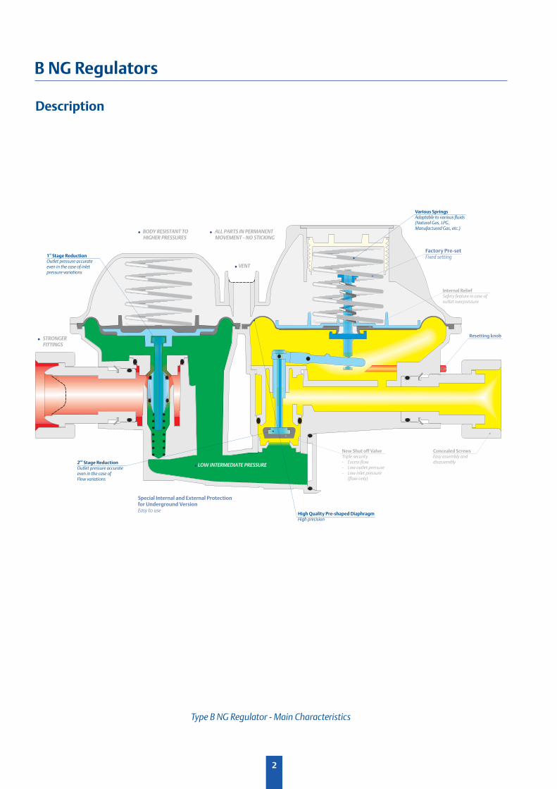
Type B NG Regulator - Main Characteristics
1 Stage Reductionst
Outlet pressure accurateeven in the case of inletpressure variations
Factory Pre-setFixed setting
2 Stage Reductionnd
Outlet pressure accurateeven in the case ofFlow variations
Special Internal and External Protectionfor Underground VersionEasy to use
New Shut off ValveTriple security- Excess flow- Low outlet pressure- Low inlet pressure
(flow only)
Concealed ScrewsEasy assembly anddisassembly
High Quality Pre-shaped DiaphragmHigh precision
Internal ReliefSafety feature in case ofoutlet overpressure
Various SpringsAdaptable to various fluids(Natural Gas, LPG,Manufactured Gas, etc.)
! LOW INTERMEDIATE PRESSURE
! VENT
! STRONGER
FITTINGS
! BODY RESISTANT TO
HIGHER PRESSURES
! ALL PARTS IN PERMANENT
MOVEMENT - NO STICKING
Resetting knob
3
B NG Regulators
Description
MAIN SAFETY FEATURES
• Downstream equipment protection
• Stronger fi ttings permitting easy and safe installation
• Body withstands higher pressures (12.5 bar for 1st stage reduction and 5 bar for 2nd stage reduction) giving exceptional resistance in the case of upstream overpressure
• All parts are in permanent movement, therefore no risk of sticking, to assure immediate response and protection of the downstream equipment
The new Type B NG residential regulator is a direct-action, spring-loaded regulator, with high performance and reinforced safety features.
A shut off valve cuts off the fl ow in the case of excessive fl ow, or when the outlet pressure drops below the set point (high gas demand or broken line), or in the case of inlet pressure dropping below the set point (network pressure drops or pipe damage).
The regulator can be manually reset after the safety function trips.
The regulator is factory preset.
The new B6 NG is interchangeable with the current angle-shaped B6 N (same key dimensions).
PERFORMANCE FEATURES
• 2 stages of reduction produce a constant outlet pressure, which is insensitive to changes in inlet pressure
• Nominal fl ow up to 10 m3/h(n) with an accuracy of AC 5
• Inlet pressure range 0.5 to 5 bar, possibility of 0.1 to 6 bar under certain conditions
• Outlet pressures 21, 27, 37 mbar (standard), others (9 to 50 mbar) available upon request
• The B NG is equipped with an internal relief valve
• A fi lter protects the regulator on the inlet side
4
B NG Regulators
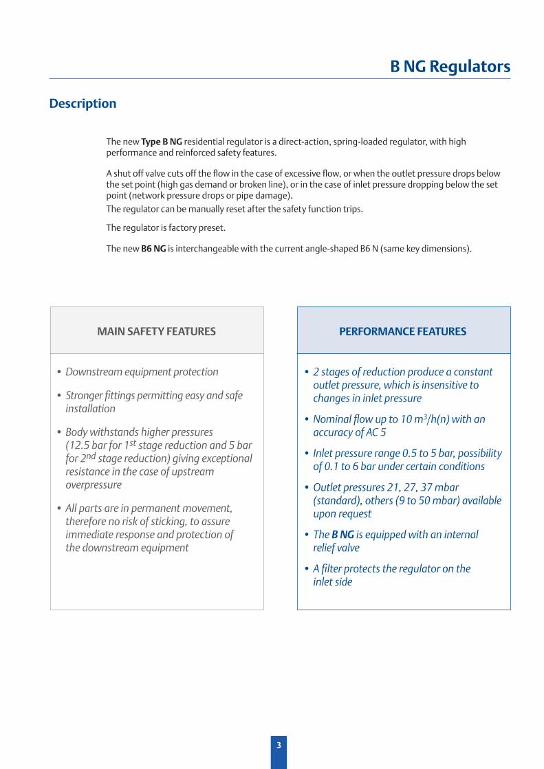
Angle-ShapeLine-Shape
• Two compact installations
• Flow up to 10 m3/h (AC 5)
• Higher inlet pressure acceptance
• New marking, easier to read in the case of cabinet installation
Larger Application & Integration Range
Inlet Pressure
Pu: 0.5 to 5 bar (0.1 to 6 bar on request)
Outlet Pressure
Pd: 9 to 50 mbar
Connection Sizes
Inlet: 3/4" sphero-conical or fl at - Others on requestOutlet: Flat joint with the following nuts: 1"1/4, 1"BS746, 1"ISO228, range for national meters, others on request
Features
Technical Features
5
B NG Regulators
Body : Zinc/Aluminum Alloy
Casing : Zinc/Aluminum Alloy
Inlet Connection : Brass
Inlet Filter : Bronze or Plastic
Outlet Connection : Brass
1st Stage Plug : Nitrile
1st Stage Disc Orifi ce : Aluminum
2nd Stage Plug : Nitrile
2nd Stage Disc Orifi ce : Brass
Diaphragms : Nitrile
Vent Screen : Stainless Steel
Vent : Plastic (option)
Material
Functional Features
Temperature
TS: -20 / +60°C (< -20°C under certain conditions)
Flow Capacity
Q: 0 to 10 m3/h(n)
Accuracy
AC: Up to 5
Lock-up Pressure Class
SG: Up to 20
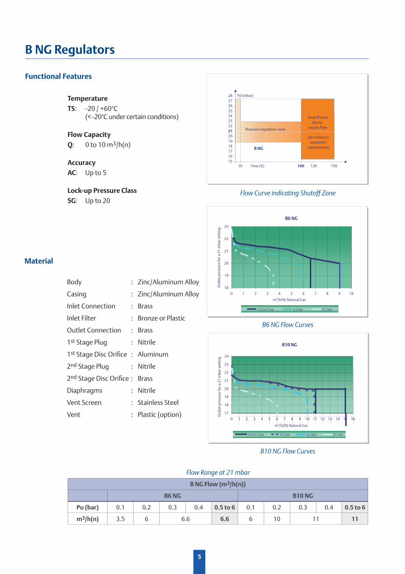
Flow Range at 21 mbar
B NG Flow (m3/h(n))
B6 NG B10 NG
Pu (bar) 0.1 0.2 0.3 0.4 0.5 to 6 0.1 0.2 0.3 0.4 0.5 to 6
m3/h(n) 3.5 6 6.6 6.6 6 10 11 11
28
27
26
25
24
23
22
21
20
19
18
17
16
1510 100 120 150Flow (%)
Pressure regulation zone
Shutoff zone
due to
excess flow
(According to
customers’
requirements)
Pd (mbar)
B6 NG
18
19
20
21
22
23
0 1 2 3 4 5 6 7 8 9 10
Ou
tle
t p
ress
ure
fo
r a
21
mb
ar
sett
ing
0.3 to 5 bar 0.2 bar 0.1 bar
m³/h(N) Natural Gas
Flow Curve indicating Shutoff Zone
B6 NG Flow Curves
B10 NG Flow Curves
B10 NG
17
18
19
20
21
22
23
24
0 1 2 3 4 5 6 7 8 9 10 11 12 13 14 15 16
m³/h(N) Natural Gas
0.4 to 5 bar 0.2 bar 0.1 bar0.3 bar
Ou
tle
t p
ress
ure
fo
r a
21
mb
ar
sett
ing
Process ManagementTM
The Emerson logo is a trademark and service mark of Emerson Electric Co. All other marks are the property of their prospective owners. Fisher is a mark owned by Fisher Controls, Inc., a
business of Emerson Process Management.
The contents of this publication are presented for informational purposes only, and while every effort has been made to ensure their accuracy, they are not to be construed as warranties or
guarantees, express or implied, regarding the products or services described herein or their use or applicability. We reserve the right to modify or improve the designs or specifi cations of such
products at any time without notice.
Emerson Process Management does not assume responsibility for the selection, use or maintenance of any product. Responsibility for proper selection, use and maintenance of any Emerson
Process Management product remains solely with the purchaser.
For further information visit www.emersonprocess.com/regulators
Natural Gas Technologies
Emerson Process ManagementRegulator Technologies, Inc.
Francel SASBusiness Park - 3 avenue Victor HugoCS 8012528008 Chartres Cedex, FranceTel: +33 (0)2 37 33 47 00Fax: +33 (0)2 37 31 46 56
O.M.T. Offi cina Meccanica Tartarini s.r.l.Via P. Fabbri, 1 I - 40013 Castel Maggiore (Bologna), Italy Tel.: +39 - 0514190611 Fax: +39 - 0514190715 E-mail: [email protected]
NCABNGEN©Emerson Process Management Regulator Technologies, Inc., 2012; All Rights Reserved
04
/20
12
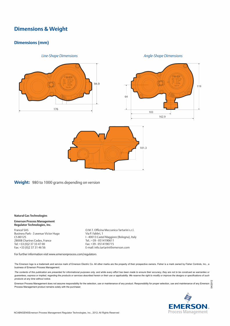
Dimensions & Weight
94.9
176
119
162.9
103
64
101.3
Angle-Shape DimensionsLine-Shape Dimensions
980 to 1000 grams depending on version
Dimensions (mm)
Weight: