axial and flexural performance of square rc columns ...axial and flexural performance of square rc...
TRANSCRIPT

University of WollongongResearch Online
Faculty of Engineering and Information Sciences -Papers: Part A Faculty of Engineering and Information Sciences
2012
Axial and flexural performance of square RCcolumns wrapped with CFRP under eccentricloadingMuhammad N. S HadiUniversity of Wollongong, [email protected]
Ida Bagus Rai WidiarsaUniversity of Wollongong, [email protected]
Research Online is the open access institutional repository for the University of Wollongong. For further information contact the UOW Library:[email protected]
Publication DetailsHadi, M. N. S. & Widiarsa, I. (2012). Axial and flexural performance of square RC columns wrapped with CFRP under eccentricloading. Journal of Composites for Construction, 16 (6), 640-649.
Axial and flexural performance of square RC columns wrapped withCFRP under eccentric loading
AbstractThe majority of studies on fiber-reinforced-polymer (FRP) strengthened concrete columns deal with columnsof a circular cross section. However, most concrete columns in the field have square or rectangular crosssections and resist eccentric loads. This paper presents the results of an experimental study on theperformance of carbon-fiber-reinforced-polymer (CFRP) wrapped square reinforced concrete (RC) columnsunder eccentric loading. The influence of the number of CFRP layers, the magnitude of eccentricity, and thepresence of vertical CFRP straps were investigated by testing 16 specimens. The specimens had thedimensions 200 × 200 × 800 mm and round corners with a radius of 34 mm. Twelve specimens were tested ascolumns and four specimens as beams. The results of this study showed that CFRP wrapping enhanced theload-carrying capacity and ductility of the columns under eccentric loading. Furthermore, the application ofthe vertical CFRP straps significantly improved the performance of the columns with large eccentricity
Keywordscfrp, under, wrapped, columns, rc, square, performance, eccentric, flexural, axial, loading
Publication DetailsHadi, M. N. S. & Widiarsa, I. (2012). Axial and flexural performance of square RC columns wrapped withCFRP under eccentric loading. Journal of Composites for Construction, 16 (6), 640-649.
This journal article is available at Research Online: http://ro.uow.edu.au/eispapers/8
Axial and Flexural Performance of Square RC ColumnsWrapped with CFRP under Eccentric Loading
Muhammad N. S. Hadi, M.ASCE1; and Ida Bagus Rai Widiarsa2
Abstract: The majority of studies on fiber-reinforced-polymer (FRP) strengthened concrete columns deal with columns of a circular crosssection. However, most concrete columns in the field have square or rectangular cross sections and resist eccentric loads. This paper presentsthe results of an experimental study on the performance of carbon-fiber-reinforced-polymer (CFRP) wrapped square reinforced concrete (RC)columns under eccentric loading. The influence of the number of CFRP layers, the magnitude of eccentricity, and the presence of verticalCFRP straps were investigated by testing 16 specimens. The specimens had the dimensions 200 × 200 × 800 mm and round corners with aradius of 34 mm. Twelve specimens were tested as columns and four specimens as beams. The results of this study showed that CFRPwrapping enhanced the load-carrying capacity and ductility of the columns under eccentric loading. Furthermore, the application ofthe vertical CFRP straps significantly improved the performance of the columns with large eccentricity. DOI: 10.1061/(ASCE)CC.1943-5614.0000301. © 2012 American Society of Civil Engineers.
CE Database subject headings: Fiber reinforced polymer; Reinforced concrete; Concrete columns; Eccentric loads; Ductility.
Author keywords: CFRP; Square reinforced concrete columns; Eccentric loading; Ductility.
Introduction
High-strength concrete (HSC) has been used widely in civilconstruction projects due to its high compressive strength and elas-tic modulus. The use of HSC instead of normal-strength concrete(NSC) would reduce significantly member size and material con-sumption. HSC members behave differently than those made ofNSC; HSC is more brittle than NSC. The failure of a HSC memberis more explosive and sudden. A review of the literature shows thatthe majority of studies on fiber-reinforced-polymer (FRP) confinedconcrete columns investigated columns with NSC (e.g., Teng et al.2002). Only a few studies investigated FRP confined columns withHSC (Li and Hadi 2003; Hadi 2007b; Eid et al. 2009).
The use of FRP composites for strengthening reinforcedconcrete members has been investigated experimentally by manyresearchers, and FRP has been applied in construction. Strengthen-ing reinforced concrete columns using FRP composites is preferredto using other materials like steel due to the high strength-to-weightratio and high corrosion resistance of FRP composites. Several in-vestigations on FRP-strengthened concrete columns have beenundertaken over the years. Most of these studies investigated thebehavior of columns under concentric loads (Kumutha et al.2007; Wang and Wu 2008; Lam and Teng 2002; Teng and Lam2004; Rousakis et al. 2007), whereas only a few studies presented
investigations of columns under eccentric loads. Consideration ofapplying eccentric loads was undertaken due to the reality that mostcolumns in the field are loaded under a combination of axial com-pression load and bending moment. Bending moment always existsin a column, even though in columns nominally carrying only axialcompression load, bending moment is introduced by unintentionalload eccentricities and by out-of-straightness of the constructed col-umn (Warner et al. 2007).
The effect of applying eccentric loads on FRP-strengthenedconcrete columns has been studied by a few researchers. Other thanthe magnitude of eccentricities, the shape of column cross sectionis an important factor that influences the confining behavior ofFRP-strengthened concrete columns. Some researchers have inves-tigated FRP-strengthened concrete columns under eccentric loads,focusing mostly on columns having a circular cross section (Li andHadi 2003; Hadi 2006a, b, 2007a, b; Bisby and Ranger 2010).Although most concrete columns in the field have square or rec-tangular cross sections rather than circular ones and may also resisteccentric loads, only a few investigations have studied concrete col-umns with square or rectangular cross sections (Parvin and Wang2001; Maaddawy 2009). Both of these studies tested small-scalesquare concrete columns constructed with normal strength con-crete. Columns tested by Parvin and Wang (2001) had no internalreinforcement and were wrapped with no layer, one layer, or twolayers of CFRP. The columns were tested under concentric andeccentric loads. Columns tested by Maaddawy (2009) had noround corners but had end corbels. The columns were unwrapped,fully wrapped, and partially wrapped with CFRP and were testedeccentrically.
Consequently, research on FRP-strengthened square or rectan-gular HSC columns under eccentric loads must still be undertakento understand their behavior and performance. This paper isdirected toward this purpose. Parameters investigated in this studyinclude the magnitude of eccentricity and the number of FRPlayers. Three different eccentricities—0, 25, and 50 mm—wereinvestigated. In relation to the number of FRP layers, unwrappedcolumns, columns wrapped with one layer, and columns wrapped
1Associate Professor, School of Civil, Mining and EnvironmentalEngineering, Univ. of Wollongong, Wollongong NSW 2522, Australia(corresponding author). E-mail: [email protected]
2Lecturer, Dept. of Civil Engineering, Univ. of Udayana, Bali 80361,Indonesia; presently, Ph.D. Scholar at the School of Civil, Mining and En-vironmental Engineering, Univ. of Wollongong, Wollongong NSW 2522,Australia. E-mail: [email protected]
Note. This manuscript was submitted on November 20, 2011; approvedon April 24, 2012; published online on April 26, 2012. Discussion periodopen until May 1, 2013; separate discussions must be submitted for indi-vidual papers. This paper is part of the Journal of Composites for Con-struction, Vol. 16, No. 6, December 1, 2012. © ASCE, ISSN 1090-0268/2012/6-640-649/$25.00.
640 / JOURNAL OF COMPOSITES FOR CONSTRUCTION © ASCE / NOVEMBER/DECEMBER 2012
J. Compos. Constr. 2012.16:640-649.
Dow
nloa
ded
from
asc
elib
rary
.org
by
UN
IVER
SITY
OF
WO
LLO
NG
ON
G o
n 12
/02/
12. C
opyr
ight
ASC
E. F
or p
erso
nal u
se o
nly;
all
right
s res
erve
d.
with three layers of CFRP were tested. Due to the significanteffect of longitudinal fiber in eccentric loading (Chaallal andShahawy 2000; Hadi 2007a), one layer of CFRP straps was appliedlongitudinally in combination with two layers of CFRP wrappedcircumferentially.
Experimental Program
The experimental program consisted in testing a total of 16 RCspecimens, of which 12 were tested under compression loadingand four under flexural loading. All specimens were tested atthe laboratories of the School of Civil, Mining and EnvironmentalEngineering at the University of Wollongong, Australia.
Design of Specimens
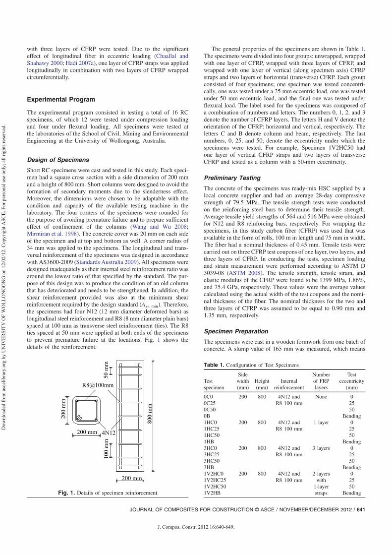
Short RC specimens were cast and tested in this study. Each speci-men had a square cross section with a side dimension of 200 mmand a height of 800 mm. Short columns were designed to avoid theformation of secondary moments due to the slenderness effect.Moreover, the dimensions were chosen to be adaptable with thecondition and capacity of the available testing machine in thelaboratory. The four corners of the specimens were rounded forthe purpose of avoiding premature failure and to prepare sufficienteffect of confinement of the columns (Wang and Wu 2008;Mirmiran et al. 1998). The concrete cover was 20 mm on each sideof the specimen and at top and bottom as well. A corner radius of34 mm was applied to the specimens. The longitudinal and trans-versal reinforcement of the specimens was designed in accordancewith AS3600-2009 (Standards Australia 2009). All specimens weredesigned inadequately as their internal steel reinforcement ratio wasaround the lowest ratio of that specified by the standard. The pur-pose of this design was to produce the condition of an old columnthat has deteriorated and needs to be strengthened. In addition, theshear reinforcement provided was also at the minimum shearreinforcement required by the design standard (Asv:min). Therefore,the specimens had four N12 (12 mm diameter deformed bars) aslongitudinal steel reinforcement and R8 (8 mm diameter plain bars)spaced at 100 mm as transverse steel reinforcement (ties). The R8ties spaced at 50 mm were applied at both ends of the specimensto prevent premature failure at the locations. Fig. 1 shows thedetails of the reinforcement.
The general properties of the specimens are shown in Table 1.The specimens were divided into four groups: unwrapped, wrappedwith one layer of CFRP, wrapped with three layers of CFRP, andwrapped with one layer of vertical (along specimen axis) CFRPstraps and two layers of horizontal (transverse) CFRP. Each groupconsisted of four specimens; one specimen was tested concentri-cally, one was tested under a 25 mm eccentric load, one was testedunder 50 mm eccentric load, and the final one was tested underflexural load. The label used for the specimens was composed ofa combination of numbers and letters. The numbers 0, 1, 2, and 3denote the number of CFRP layers. The letters H and V denote theorientation of the CFRP: horizontal and vertical, respectively. Theletters C and B denote column and beam, respectively. The lastnumbers, 0, 25, and 50, denote the eccentricity under which thespecimens were tested. For example, Specimen 1V2HC50 hadone layer of vertical CFRP straps and two layers of transverseCFRP and tested as a column with a 50-mm eccentricity.
Preliminary Testing
The concrete of the specimens was ready-mix HSC supplied by alocal concrete supplier and had an average 28-day compressivestrength of 79.5 MPa. The tensile strength tests were conductedon the reinforcing steel bars to determine their tensile strength.Average tensile yield strengths of 564 and 516 MPa were obtainedfor N12 and R8 reinforcing bars, respectively. For wrapping thespecimens, in this study carbon fiber (CFRP) was used that wasavailable in the form of rolls, 100 m in length and 75 mm in width.The fiber had a nominal thickness of 0.45 mm. Tensile tests werecarried out on three CFRP test coupons of one layer, two layers, andthree layers of CFRP. In conducting the tests, specimen loadingand strain measurement were performed according to ASTM D3039-08 (ASTM 2008). The tensile strength, tensile strain, andelastic modulus of the CFRP were found to be 1399 MPa, 1.86%,and 75.4 GPa, respectively. These values were the average valuescalculated using the actual width of the test coupons and the nomi-nal thickness of the fiber. The nominal thickness for the two andthree layers of CFRP was assumed to be equal to 0.90 mm and1.35 mm, respectively.
Specimen Preparation
The specimens were cast in a wooden formwork from one batch ofconcrete. A slump value of 165 mm was measured, which means
Fig. 1. Details of specimen reinforcement
Table 1. Configuration of Test Specimens
Testspecimen
Sidewidth(mm)
Height(mm)
Internalreinforcement
Numberof FRPlayers
Testeccentricity
(mm)
0C0 200 800 4N12 andR8 100 mm
None 00C25 250C50 500B Bending1HC0 200 800 4N12 and
R8 100 mm1 layer 0
1HC25 251HC50 501HB Bending3HC0 200 800 4N12 and
R8 100 mm3 layers 0
3HC25 253HC50 503HB Bending1V2HC0 200 800 4N12 and
R8 100 mm2 layerswith
1-layerstraps
01V2HC25 251V2HC50 501V2HB Bending
JOURNAL OF COMPOSITES FOR CONSTRUCTION © ASCE / NOVEMBER/DECEMBER 2012 / 641
J. Compos. Constr. 2012.16:640-649.
Dow
nloa
ded
from
asc
elib
rary
.org
by
UN
IVER
SITY
OF
WO
LLO
NG
ON
G o
n 12
/02/
12. C
opyr
ight
ASC
E. F
or p
erso
nal u
se o
nly;
all
right
s res
erve
d.

the concrete had proper workability. The concrete was poured into aformwork in three stages; in each stage the concrete was compactedadequately using a vibrator to ensure an even dispersion of con-crete. After casting, all the specimens were placed under wet hes-sian rugs and covered with plastic sheets to maintain their moistureconditions. The specimens and hessian rugs were watered twice aday until the formwork was removed at 14 days after casting. Thecuring process lasted 28 days.
Surface preparation was done by cleaning and grinding the sur-face of the specimens. Twelve specimens were wrapped with CFRPusing a wet layup technique. A mixture of epoxy resin and hardenerat a 5∶1 ratio was used as an adhesive. The surface was coated firstwith epoxy resin then the first CFRP layer in predefined orienta-tion. The layer was saturated with resin before the subsequent layerwas applied to ensure a perfect bond between the layers. Similarly,the final layer was also saturated with epoxy resin. The columnwas wrapped strap by strap in either the transverse or longitudinaldirection, with no overlap between straps. An overlap of 100 mmwas applied only at the end of the final layer of each strap in thetransverse direction. The wrapped specimens were then placed inroom temperature for a minimum of 14 days to allow curing of theepoxy resin.
Specimen Testing
Twelve specimens were tested as columns under axial compressionload, and four specimens were tested as beams under flexural load.The Denison 5000 kN compression testing machine was used totest all the specimens until failure. The column ends were leveledfirst for compression testing to obtain a uniform distributed loadapplied to the entire face. For this purpose, both ends of the col-umns were capped with high-strength plaster. To apply an eccentricload on the column, a loading mechanism (Fig. 2) was designedand a new set of loading heads made with high-strength steel plate(Fig. 3) was manufactured. The loading heads were attached at bothends of the column. The loading heads consisted of two parts: a25 mm thick steel plate, called a bottom plate, that had a ball joint,and a square 50 mm thick steel plate, called an adaptor plate. Thebottom plate transferred the load generated by the machine to theadaptor plate through the ball joint, which had a designed eccen-tricity with the column. Then the adaptor plate exerted the load tothe column. For concentric loading, only adaptor plates were usedto apply the load.
Two different monitoring systems were used to measure thedisplacement of the columns. For concentric loading, one LVDTwas connected directly to the testing machine to measure the axialdisplacement of the column during the test. Data read from thisLVDT were recorded at the same time as load data were recordedby the testing machine. A second LVDT, a laser LVDT, was alsoused in addition to the first one for eccentric load to measure thelateral deflection (δ) of the column. The second LVDT was placedhorizontally near the mid-height of the column. When the specimenand the instrumentation were placed in position and initial calibra-tion was done, the compression testing then started. The columnwas tested under displacement control with a loading rate of0.5 mm=min, and the end point position was set at 50 mm. A photoof a typical compression testing is shown in Fig. 4.
As mentioned previously, four specimens were tested as beamsunder flexural loading with a span of 700 mm. Pure bending wasapplied to the specimens by means of a four-point loading todetermine the flexural capacity of the specimens without axial load.Two rigs, top and bottom, were used to exert the load generated bythe Denison compression testing machine to the beam specimens.The bottom rig was placed diagonally on the bottom plate (loading
(a)
(b)
Fig. 2. Developed eccentric loading mechanism: (a) plan view;(b) Section A-A
Fig. 3. Loading head: (a) adaptor plate; (b) bottom plate with ball joint
Fig. 4. Typical compression testing setup
642 / JOURNAL OF COMPOSITES FOR CONSTRUCTION © ASCE / NOVEMBER/DECEMBER 2012
J. Compos. Constr. 2012.16:640-649.
Dow
nloa
ded
from
asc
elib
rary
.org
by
UN
IVER
SITY
OF
WO
LLO
NG
ON
G o
n 12
/02/
12. C
opyr
ight
ASC
E. F
or p
erso
nal u
se o
nly;
all
right
s res
erve
d.
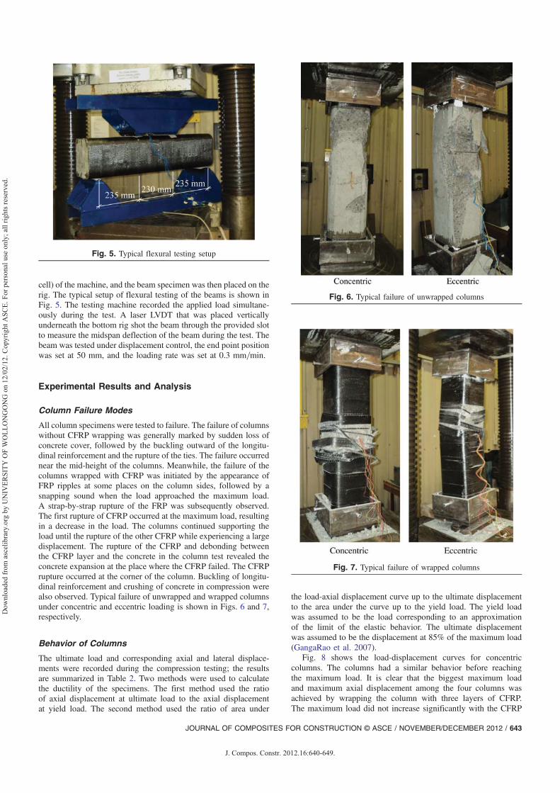
cell) of the machine, and the beam specimen was then placed on therig. The typical setup of flexural testing of the beams is shown inFig. 5. The testing machine recorded the applied load simultane-ously during the test. A laser LVDT that was placed verticallyunderneath the bottom rig shot the beam through the provided slotto measure the midspan deflection of the beam during the test. Thebeam was tested under displacement control, the end point positionwas set at 50 mm, and the loading rate was set at 0.3 mm=min.
Experimental Results and Analysis
Column Failure Modes
All column specimens were tested to failure. The failure of columnswithout CFRP wrapping was generally marked by sudden loss ofconcrete cover, followed by the buckling outward of the longitu-dinal reinforcement and the rupture of the ties. The failure occurrednear the mid-height of the columns. Meanwhile, the failure of thecolumns wrapped with CFRP was initiated by the appearance ofFRP ripples at some places on the column sides, followed by asnapping sound when the load approached the maximum load.A strap-by-strap rupture of the FRP was subsequently observed.The first rupture of CFRP occurred at the maximum load, resultingin a decrease in the load. The columns continued supporting theload until the rupture of the other CFRP while experiencing a largedisplacement. The rupture of the CFRP and debonding betweenthe CFRP layer and the concrete in the column test revealed theconcrete expansion at the place where the CFRP failed. The CFRPrupture occurred at the corner of the column. Buckling of longitu-dinal reinforcement and crushing of concrete in compression werealso observed. Typical failure of unwrapped and wrapped columnsunder concentric and eccentric loading is shown in Figs. 6 and 7,respectively.
Behavior of Columns
The ultimate load and corresponding axial and lateral displace-ments were recorded during the compression testing; the resultsare summarized in Table 2. Two methods were used to calculatethe ductility of the specimens. The first method used the ratioof axial displacement at ultimate load to the axial displacementat yield load. The second method used the ratio of area under
the load-axial displacement curve up to the ultimate displacementto the area under the curve up to the yield load. The yield loadwas assumed to be the load corresponding to an approximationof the limit of the elastic behavior. The ultimate displacementwas assumed to be the displacement at 85% of the maximum load(GangaRao et al. 2007).
Fig. 8 shows the load-displacement curves for concentriccolumns. The columns had a similar behavior before reachingthe maximum load. It is clear that the biggest maximum loadand maximum axial displacement among the four columns wasachieved by wrapping the column with three layers of CFRP.The maximum load did not increase significantly with the CFRP
Fig. 5. Typical flexural testing setup
Fig. 6. Typical failure of unwrapped columns
Fig. 7. Typical failure of wrapped columns
JOURNAL OF COMPOSITES FOR CONSTRUCTION © ASCE / NOVEMBER/DECEMBER 2012 / 643
J. Compos. Constr. 2012.16:640-649.
Dow
nloa
ded
from
asc
elib
rary
.org
by
UN
IVER
SITY
OF
WO
LLO
NG
ON
G o
n 12
/02/
12. C
opyr
ight
ASC
E. F
or p
erso
nal u
se o
nly;
all
right
s res
erve
d.

wrapping. However, wrapping columns with CFRP enhanced theperformance of the columns by increasing their displacement atfailure, meaning more ductility. Increases in the maximum loadof 1, 8.4, and 10.4% relative to the unwrapped column wereachieved for Columns 1HC0, 1V2HC0, and 3HC0, respectively.This insignificant increase in strength was obtained due to theuse of HSC, where in nature HSC is brittle. When approachingthe ultimate load, only a small number of microcracks developedin the concrete and the failure occurred suddenly with the appear-ance of a big crack.
The axial and lateral displacements versus the applied loadcurves for columns tested under 25 mm eccentric load are shownin Fig. 9. All columns failed in compression. FRP rupture occurredin all wrapped columns before failure. Column 1HC25 had 6.5%higher maximum load than the unwrapped column. Increases inmaximum load of 17.8 and 16.4% were achieved for Columns1V2HC25 and 3HC25, respectively. However, Column 3HC25showed a better performance than Column 1V2HC25 by havinga higher ductility (Table 2). Theoretically, Column 3HC25 shouldhave had a higher maximum load than Column 1V2HC25. Thepresence of vertical straps that were bonded first to the concreteand then wrapped with two layers of CFRP also contributed tothe confinement effect. Similarly, in concentric columns, Column1HC0 had only a 1% higher maximum load than Column 0C0,whereas Column 3HC0 had a 2% higher maximum load thanColumn 1V2HC0.
Fig. 10 shows the axial and lateral displacements versus theapplied load curves for columns tested under 50 mm eccentric load.Failure in compression was also observed in all columns with
cracks in the tension face near the mid-height of the columns.FRP rupture occurred after the maximum load was reached, fol-lowed by an increase in displacement. Column 1HC50 had7.3% increase in maximum load and a better performance thanthe unwrapped column. A similar increase in maximum load of14.8% was achieved for Columns 1V2HC50 and 3HC50. Column1V2HC50 had a higher ductility than Column 3HC50 (Table 2).
Tests of the 12 column specimens revealed an increase in themaximum load of the columns resulting from wrapping columnswith CFRP. An important advantage was achieved: all the wrappedcolumns showed a better performance than the unwrapped col-umns, as indicated by their ductility. From the load-displacement
Table 2. Column Test Results
Testspecimen
Ultimateload (kN)
Displacement atultimate load (mm) Axial displacement (mm) Ductility
Axial Lateral At yield At 85% ultimate load Maximum Method 1a Method 2a
0C0 3,248 4.58 — 3.21 4.71 5.20 1.47 2.091HC0 3,279 4.53 — 3.20 4.75 13.88 1.48 2.181V2HC0 3,522 5.00 — 3.57 8.57 19.57 2.40 4.393HC0 3,585 5.29 — 3.63 13.47 18.51 3.71 7.160C25 1,950 3.91 1.87 2.93 4.12 6.25 1.41 1.871HC25 2,076 4.45 2.25 3.11 5.07 9.90 1.63 2.681V2HC25 2,296 4.76 2.44 3.19 8.30 15.94 2.60 5.173HC25 2,269 4.48 2.11 3.18 11.17 14.95 3.52 7.450C50 1,336 3.86 2.65 2.93 4.01 4.66 1.37 1.901HC50 1,433 4.05 2.32 3.02 4.98 13.20 1.65 2.841V2HC50 1,533 3.99 2.52 2.88 9.22 14.55 3.20 7.063HC50 1,534 3.99 3.19 2.89 6.64 13.09 2.30 4.66aRefer to the section “Behavior of Columns” for a definition of the methods.
35004000
2 0030003500
)
20002500
ad (
kN
10001500L
oa
0500
00 5 10 15 20
A i l di l t ( )Axial displacement (mm)
0C0 1HC0 1V2HC0 3HC0
Fig. 8. Load-displacement curves for columns tested under concentricloading
2400
1600
2000
N)
1200
1600
ad (
kN
800Loa
0
400
0-35 -30 -25 -20 -15 -10 -5 0 5 10 15 20
Lateral displ. (mm) Axial displ. (mm)
0C25 1HC25 1V2HC25 3HC25
Fig. 9. Load-displacement curves for columns tested under 25-mmeccentricity
1600
1200
)
800d (k
N)
400
Loa
d
0
400
0-45 -40 -35 -30 -25 -20 -15 -10 -5 0 5 10 15 20
l di l ( ) A i l di l ( )Lateral displ. (mm) Axial displ. (mm)
0C50 1HC50 1V2HC50 3HC50
Fig. 10. Load-displacement curves for columns tested under 50-mmeccentricity
644 / JOURNAL OF COMPOSITES FOR CONSTRUCTION © ASCE / NOVEMBER/DECEMBER 2012
J. Compos. Constr. 2012.16:640-649.
Dow
nloa
ded
from
asc
elib
rary
.org
by
UN
IVER
SITY
OF
WO
LLO
NG
ON
G o
n 12
/02/
12. C
opyr
ight
ASC
E. F
or p
erso
nal u
se o
nly;
all
right
s res
erve
d.

curves of the columns, it can be seen that the displacementincreased with increasing load until the maximum load was ap-proached. Then, for unwrapped columns the load suddenly droppedwith loss of concrete cover. For wrapped columns, the first CFRPrupture occurred when the maximum load was reached, followedby a decrease in load and a sharp increase in displacement. At thisstage, the effect of confinement was active to the controlling of thecolumn behavior. Some CFRP rupture still occurred until the col-umn failed. Rupture of longitudinal straps was also observed in thecolumns wrapped longitudinally with CFRP straps.
Influence of Eccentricity
To describe the influence of eccentricity on the behavior of the col-umns, load-displacement curves of the 12 columns in relation to theeccentricity were plotted as shown in Fig. 11. It can be clearly seenthat the eccentricity of loading reduced the load carrying capacityand performance of the columns.
Behavior of Beams
All beams were tested to failure. Fig. 12 shows the load-midspandeflection of the beams tested under flexure. It can be seen thatwrapping the beam in the hoop direction with CFRP did not im-prove significantly the load carrying capacity and performance ofthe beam under flexural loading. However, the presence of CFRPstraps applied longitudinally in Beam 1V2HB showed a large im-provement in its load carrying capacity compared to the otherbeams. As in columns with vertical straps, a consequent strap-by-strap rupture of the longitudinal strap was also observed in beam1V2HB. The first rupture of the strap resulted in a sudden decreasein load, and then the beam still resisted the load under increasingdisplacement until the second peak load was reached. The next rup-ture of the strap resulted in a drop of load. Several ruptures of the
straps occurred until the beam failed (Fig. 12). Yielding of the ten-sile reinforcing bars was observed in all beams. Table 3 summarizesthe analysis results of the beams. It can be seen that Beam 1V2HBhad the highest load and ductility of the four beams. Wrapping abeam in the hoop direction with one layer of CFRP had no influ-ence on beam ductility. However, wrapping with three layers ofCFRP increased beam ductility slightly. Calculations of beam duc-tility were done using methods similar to those used for columns.
Axial Load-Bending Moment Interaction Diagrams ofColumns
Axial load-bending moment interaction diagrams were constructedto describe the axial load and bending moment capacity of the col-umns tested in this study. Any point on the diagrams may represent
0
500
1000
1500
2000
2500
3000
3500
0 2 4 6 8
Loa
d (k
N)
Axial displacement (mm)
0C0
0C25
0C50
0
500
1000
1500
2000
2500
3000
3500
0 5 10 15
Loa
d (k
N)
Axial displacement (mm)
1HC0
1HC25
1HC50
0
500
1000
1500
2000
2500
3000
3500
4000
0 5 10 15 20
Loa
d (k
N)
Axial displacement (mm)
3HC0
3HC25
3HC50
0
500
1000
1500
2000
2500
3000
3500
4000
0 5 10 15 20
Loa
d (k
N)
Axial displacement (mm)
1V2HC0
1V2HC25
1V2HC50
(a) (b)
(d)(c)
Fig. 11. Load-displacement curves of columns with different eccentricities
600
400
500
300
400
d (k
N)
200Loa
d
0
100
00 5 10 15 20 25 30
Midspan deflection (mm)
0B 1HB 1V2HB 3HB
Fig. 12. Load-midspan deflection curves of beams tested underflexural loading
JOURNAL OF COMPOSITES FOR CONSTRUCTION © ASCE / NOVEMBER/DECEMBER 2012 / 645
J. Compos. Constr. 2012.16:640-649.
Dow
nloa
ded
from
asc
elib
rary
.org
by
UN
IVER
SITY
OF
WO
LLO
NG
ON
G o
n 12
/02/
12. C
opyr
ight
ASC
E. F
or p
erso
nal u
se o
nly;
all
right
s res
erve
d.

a condition of a column under a concentric load, an eccentric load,or a pure bending. The procedure described in Warner et al. (2007)for developing the interaction diagram of conventional RC columnswas followed. Full details are given in Warner et al. (2007). Theanalysis to construct the interaction diagram of an FRP-confinedRC column was carried out based on principles of equilibriumand strain compatibility applied to a conventional RC column.The only difference in the analysis of confined column was theuse of an FRP-confined stress-strain curve to replace the stress-strain curve of unconfined concrete. The stress-strain curve ofconfined concrete proposed by Teng et al. (2002) was adopted here.The model is divided into two portions. The first portion is theascending branch of the curve from zero stress to stress equal tof 0c, which describes the stress-strain relationship of unconfined
concrete. In the second portion, the stress beyond f 0c, the concrete
stress increases linearly until reaching the stress of the confinedconcrete (f 0
cc) with the corresponding confined-concrete strain(ε 0cc). The second portion describes the stress-strain relationshipof confined concrete.
In developing axial load-bending moment interaction diagrams,the axial load and the bending moment were calculated first. Theaxial concentric load capacity of an unconfined RC column (Nuo)was calculated using the following formula (Warner et al. 2007):
Nuo ¼ α1f 0cAg þ fsyAs (1)
where f 0c = compressive strength of the unconfined concrete; Ag =
cross-sectional area of column; fsy = yield strength of longitudinalsteel reinforcement; and As = total cross-sectional area of longitu-dinal steel reinforcement. Because theoretical values were used todevelop the interaction N-M diagrams (which were really designdiagrams), the factor α1 was used, as recommended by Australianstandard AS3600-2009 (Standards Australia 2009). The standardprovides a value of α1 ¼ 1.0 − 0.003f 0
c within the limits0.72 ≤ α1 ≤ 0.85. The value of α1 for concrete with compressivestrength up to 50 MPa is 0.85, which is similar to that recom-mended by ACI318-2008 [American Concrete Institute (ACI)2008]. The value of α1 used in the axial load calculation for thecase of wrapped columns was different than that used for un-wrapped columns. For unwrapped columns (Column 0C0) witha compressive strength of 79.5 MPa, the value of α1 is 0.762.Meanwhile, for wrapped columns, i.e., Columns 1HC0, 3HC0,and 1V2HC0, with compressive strength as shown in Table 4,the corresponding values of α1 are 0.734, 0.72, and 0.72, respec-tively. A minimum value of α1 was used for Columns 3HC0 and1V2HC0.
When an FRP-wrapped concrete column is subjected to com-pression, FRP confinement resists the expansion of the concretecore. Thus, the FRP is subjected to tension in the hoop direction.For a circular column, the lateral confining pressure is uniformlydistributed and can be calculated as follows (Lam and Teng 2002):
fl ¼2ffrptfrp
d(2)
where fl = lateral confining pressure; ffrp = tensile strength of FRPin hoop direction; tfrp = total thickness of FRP; and d = diameter ofconfined concrete.
The following formula, proposed by Richart et al. (1928), hasbeen used by many researchers for predicting the compressivestrength of FRP-confined circular concrete columns (Lam and Teng2002):
f 0cc
f 0c¼ 1þ k1
flf 0c
(3)
where f 0cc = the compressive strength of the confined concrete and
k1 = the confinement effectiveness coefficient.FRP-wrapped rectangular concrete columns have a different re-
sponse than FRP-wrapped circular concrete columns, where theconcrete is not uniformly confined by the FRP jacket. The nonun-iformity of confinement reduces the confinement effectiveness ofthe FRP, and, furthermore, the compressive strength of confinedconcrete varies over a given section (Mirmiran et al. 1998). To pre-dict the confined concrete strength of rectangular column, the shapefactor (ks) is taken into account to consider the effect of nonuni-formity of confinement. Thus, Eq. (3) is modified by Teng et al.(2002) as follows:
f 0cc
f 0c¼ 1þ k1ks
flf 0c
(4)
Table 3. Beam Test Results
Test specimen 0B 1HB 1V2HB 3HB
Ultimate load (kN) 241 247 518 260Deflection at ultimate load (mm) 11.94 11.03 11.85 14.95Yield deflection (mm) 4.06 4.20 4.15 3.89Maximum deflection (mm) 20.33 20.24 25.47 22.78Ductility, Method 1a 5.01 4.82 6.13 5.86Ductility, Method 2a 9.74 10.41 15.12 12.50aRefer to the section “Behavior of Columns” for a definition of themethods.
Table 4. Compressive Strength of Wrapped Concrete Columns
Columns
Compressive Strength, f 0cc (MPa)
Difference(%)
Theoretical(f 0
cc:the)a
Experimental(f 0
cc: exp)
1HC0 88.8 105.6 15.93HC0 107.3 118.6 9.51V2HC0 98.0 116.3 15.7aCalculated using Eq. (4).
Table 5. Experimental Bending Moment Capacity of Columns
Specimen
Maximumload,
Nmax (kN)
Deflectionat maximum
load,δ (mm)
M1 ¼ Nmaxe(kN-m)
M2 ¼ Nmaxðeþ δÞ(kN-m)
0C0 3,248 0 0 00C25 1,950 1.87 48.75 52.390C50 1,336 2.65 66.80 70.330B 241 11.94 28.30a 28.30a
1HC0 3,279 0 0 01HC25 2,076 2.25 51.90 56.581HC50 1,433 2.32 71.65 74.971HB 247 11.03 29.01a 29.01a
3HC0 3,585 0 0 03HC25 2,269 2.11 56.73 61.523HC50 1,534 3.19 76.70 81.603HB 260 14.95 30.52a 30.52a
1V2HC0 3,522 0 0 01V2HC25 2,296 2.44 57.40 63.011V2HC50 1,533 2.52 76.65 80.511V2HB 518 11.85 60.87a 60.87a
aCalculated using Eq. (10).
646 / JOURNAL OF COMPOSITES FOR CONSTRUCTION © ASCE / NOVEMBER/DECEMBER 2012
J. Compos. Constr. 2012.16:640-649.
Dow
nloa
ded
from
asc
elib
rary
.org
by
UN
IVER
SITY
OF
WO
LLO
NG
ON
G o
n 12
/02/
12. C
opyr
ight
ASC
E. F
or p
erso
nal u
se o
nly;
all
right
s res
erve
d.
ks ¼�bh
�Ae
Ac(5)
Ae
Ac¼ 1 − ½ðb=hÞðh − 2RcÞ2 þ ðh=bÞðb − 2RcÞ2�=ð3AgÞ − ρsc
1 − ρsc(6)
Ag ¼ bh − ð4 − πÞR2c (7)
where b and h = width and height of column section, respectively(in the case of a square section, b ¼ h); Ae = effective confinement
area; Ac = total area of concrete; Rc = corner radius; and ρsc =cross-sectional area ratio of longitudinal steel. A value ofk1 ¼ 2.98 was proposed for predicting the strength of FRP-confined concrete columns having a rectangular or square crosssection. fl in Eq. (4) becomes an equivalent confining pressurethat is interpreted as the confining pressure provided by theFRP jacket to an equivalent circular column (with the diagonallength D) and proposed as follows:
fl ¼2ffrptfrp
D¼ 2ffrptfrpffiffiffiffiffiffiffiffiffiffiffiffiffiffiffi
h2 þ b2p (8)
The theoretical compressive strengths of the CFRP-wrappedcolumns investigated in this study are presented in Table 4 andcompared with the experimental results. The 28-day concrete com-pressive strength was taken as the unconfined concrete compressivestrength to calculate the compressive strength of the confinedconcrete. It can be seen that the confined compressive strengthobtained from the theoretical results were 15.9, 9.5, and 15.7%smaller than that obtained from the experimental results for Col-umns 1HC0, 3HC0, and 1V2HC0, respectively. Since the compres-sive strengths of the CFRP-wrapped columns were obtained, theaxial concentric load capacity of the wrapped column (Nuc) werecalculated using Eq. (1) by replacing f 0
c with f 0cc, as formulated in
Eq. (4). As a comparison, another strength model, proposed by Wuand Wang (2009), was used to predict the strength of confined col-umns. Values of f 0
cc=f 0c of 1.089, 1.173, and 1.255 for Columns
1HC, 1V2HC, and 3HC, respectively, were obtained, which weresmaller than those calculated using Eq. (4). Eq. (4) yielded values
40000C
3000
35000C
1HC
3HC
2000
2500
N (
kN) 3HC
1V2HC
1500
2000
Loa
d N
500
1000L
0
500
0 20 40 60 80 1000 20 40 60 80 100Bending moment M2 (kN-m)
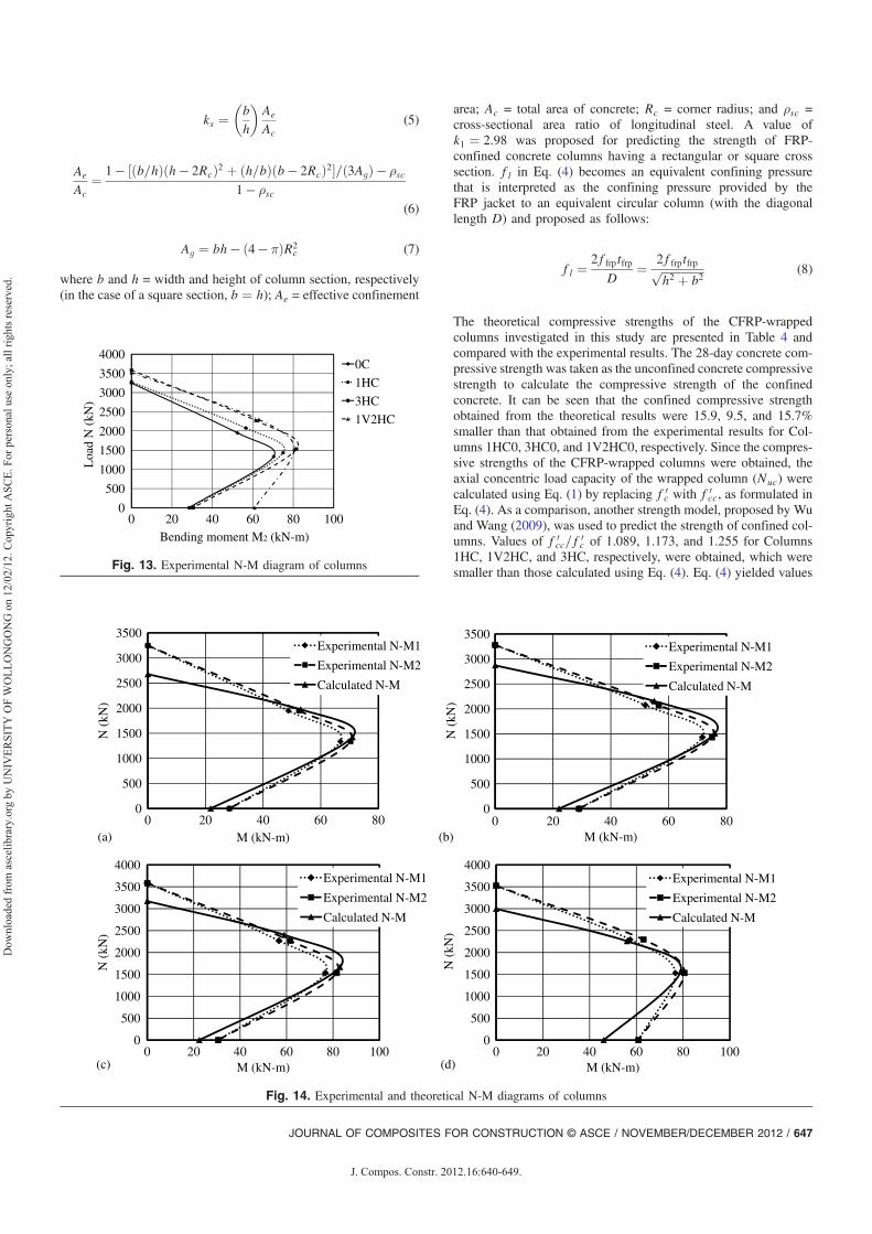
Fig. 13. Experimental N-M diagram of columns
0
500
1000
1500
2000
2500
3000
3500
0 20 40 60 80
N (
kN)
M (kN-m)
Experimental N-M1
Experimental N-M2
Calculated N-M
0
500
1000
1500
2000
2500
3000
3500
0 20 40 60 80
N (
kN)
M (kN-m)
Experimental N-M1
Experimental N-M2
Calculated N-M
0
500
1000
1500
2000
2500
3000
3500
4000
0 20 40 60 80 100
N (
kN)
M (kN-m)
Experimental N-M1
Experimental N-M2
Calculated N-M
0
500
1000
1500
2000
2500
3000
3500
4000
0 20 40 60 80 100
N (
kN)
M (kN-m)
Experimental N-M1
Experimental N-M2
Calculated N-M
(a)
(c) (d)
(b)
Fig. 14. Experimental and theoretical N-M diagrams of columns
JOURNAL OF COMPOSITES FOR CONSTRUCTION © ASCE / NOVEMBER/DECEMBER 2012 / 647
J. Compos. Constr. 2012.16:640-649.
Dow
nloa
ded
from
asc
elib
rary
.org
by
UN
IVER
SITY
OF
WO
LLO
NG
ON
G o
n 12
/02/
12. C
opyr
ight
ASC
E. F
or p
erso
nal u
se o
nly;
all
right
s res
erve
d.

of f 0cc=f 0
c of 1.125, 1.213, and 1.355 for the correspondingcolumns.
The bending moment capacity (M) of the eccentrically loadedcolumns, including the secondary moments, was calculated bymultiplying the maximum load capacity (Nmax) and the sum ofeccentricity (e) and lateral deflection (δ) at the maximum loadas follows:
M ¼ Nmaxðeþ δÞ (9)
However, the bending moment capacity of beams was calculatedusing
M ¼ P2a (10)
where P = maximum load applied to the specimen with four-pointloading apparatus and a = shear span length, or the distancebetween the support and the closer loading point (a ¼ 235 mmin this study).
The bending moment capacity of the investigated columns isreported in Table 5, and the experimental interaction diagram ofthe columns is shown in Fig. 13. It can be seen that wrapping acolumn with one layer of CFRP increased slightly the axial loadand bending moment capacity of the eccentrically loaded columns.A larger increment than that was obtained in column wrapped withthree layers of CFRP and in the columns wrapped with one layerof vertical straps and two layers of CFRP. The only incrementin bending moment capacity was obtained in columns that hadvertical CFRP straps. The presence of the CFRP straps applied lon-gitudinally contributed an important effect to the bending capacityof the column.
Fig. 14 shows the calculated and experimental interactiondiagrams of Columns 0C, 1HC, 3HC, and 1V2HC, respectively.It can be seen from those figures that under eccentric loadingthe calculated interaction diagram gave values that were close tothe experimental results. However, the calculated axial loads ofall columns under concentric loading were smaller than those ofthe experimental results.
Conclusions
A total of 16 square RC specimens with CFRP wrapping weretested in this study to investigate the influence of eccentricity,number of layers, and presence of vertical straps on specimenbehavior and load carrying capacity. Twelve columns were testedunder compression loading and four beams were tested underflexural loading. Based on the experimental work carried out in thisstudy, the following conclusions were drawn:1. CFRP wrapping had a more significant effect on the maximum
load of eccentrically loaded columns compared to concentri-cally loaded columns.
2. No significant increase in maximum load was obtained whenthe columns were wrapped with one layer of CFRP.
3. Increasing the number of the CFRP layers resulted in anincrease in the load and the performance of the columns.
4. The CFRP wrapping enhanced the performance of the col-umns by postponing the rupture of the concrete and reinforce-ment, which means it increased the column ductility. Similarresults were obtained in beams tested in flexure.
5. In columns with a large eccentricity, which means with a largebending moment, the presence of CFRP straps producedhigher ductility than in columns wrapped horizontally witha similar number of CFRP layers.
6. Using an existing strength model to estimate the capacity ofCFRP column yielded strength magnitudes that were lowerthan the experimental ones. This observation shows thatthe model yields good predictions of the strength of CFRP-wrapped columns.
7. The theoretical axial load-bending moment interaction dia-gram shows values that are close to those of the experimentalresult, except at the point under concentric load.
Finally, the use of longitudinal FRP layers can be recommendedin combination with FRP wrapped circumferentially to enhance theperformance of columns loaded eccentrically.
References
American Concrete Institute (ACI). (2008). “Building code requirementsfor structural concrete and commentary.” ACI 318-08, Farmington Hills,MI.
ASTM. (2008). “Standard test method for tensile properties of polymermatrix composite materials.” ASTM D 3039-08, Philadelphia.
Bisby, L., and Ranger, M. (2010). “Axial-flexural interaction in circularFRP-confined reinforced concrete columns.” Constr. Build. Mater.,24(9), 1672–1681.
Chaallal, O., and Shahawy, M. (2000). “Performance of fiber-reinforcedpolymer-wrapped reinforced concrete column under combinedaxial-flexural loading.” ACI Struct. J., 97(4), 659–668.
Eid, R., Roy, N., and Paultre, P. (2009). “Normal- and high-strengthconcrete circular elements wrapped with FRP composites.” J. Compos.Constr., 13(2), 113–124.
GangaRao, H. V. S., Taly, N., and Vijay, P. V. (2007). Reinforced concretedesign with FRP composites, CRC, London.
Hadi, M. N. S. (2006a). “Behaviour of FRP wrapped normal strengthconcrete columns under eccentric loading.” Compos. Struct., 72(4),503–511.
Hadi, M. N. S. (2006b). “Comparative study of eccentrically loaded FRPwrapped columns.” Compos. Struct., 74(2), 127–135.
Hadi, M. N. S. (2007a). “Behaviour of FRP strengthened concrete columnsunder eccentric compression loading.” Compos. Struct., 77(1), 92–96.
Hadi, M. N. S. (2007b). “The behaviour of FRP wrapped HSC columnsunder different eccentric loads.” Compos. Struct., 78(4), 560–566.
Kumutha, R., Yaidyanathan, R., and Palanichamy, M. S. (2007). “Behav-iour of reinforced concrete rectangular columns strengthened usingGFRP.” Cem. Concr. Compos., 29(8), 609–615.
Lam, L., and Teng, J. G. (2002). “Strength model for fiber-reinforcedplastic-confined concrete.” J. Struct. Eng., 128(5), May, 612–623.
Li, J., and Hadi, M. N. S. (2003). “Behaviour of externally confined highstrength concrete columns under eccentric loading.” Compos. Struct.,62(2), 145–153.
Maaddawy, T. E. (2009). “Strengthening of eccentrically loaded reinforcedconcrete columns with fiber-reinforced polymer wrapping system: Ex-perimental investigation and analytical modeling.” J. Compos. Constr.,13(1), 13–24.
Mirmiran, A., Shahawy, M., Samaan, M., Echary, H. E., Mastrapa, J. C.,and Pico, O. (1998). “Effect of column parameters on FRP-confinedconcrete.” J. Compos. Constr., 2(4), 175–185.
Parvin, A., and Wang, W. (2001). “Behavior of FRP jacketed concretecolumns under eccentric loading.” J. Compos. Constr., 5(3), 146–152.
Richart, F. E., Brandtzaeg, A., and Brown, R. L. (1928). “A study ofthe failure of concrete under combined compressive stresses.” BulletinNo. 185, Engineering Experimental Station, Univ. of Illinois at Urbana-Champaign, Urbana-Champaign, IL.
Rousakis, T. C., Karabinis, A. I., and Kiousis, P. D. (2007). “FRP-confinedconcrete members: Axial compression experiments and plasticitymodeling.” Eng. Struct., 29(7), 1343–1353.
Standards Australia. (2009). “Concrete structures.” AS3600-2009, Sydney,Australia.
Teng, J. G., Chen, J. F., Smith, S. T., and Lam, L. (2002). FRP-strengthenedRC structures, Wiley, West Sussex, UK.
648 / JOURNAL OF COMPOSITES FOR CONSTRUCTION © ASCE / NOVEMBER/DECEMBER 2012
J. Compos. Constr. 2012.16:640-649.
Dow
nloa
ded
from
asc
elib
rary
.org
by
UN
IVER
SITY
OF
WO
LLO
NG
ON
G o
n 12
/02/
12. C
opyr
ight
ASC
E. F
or p
erso
nal u
se o
nly;
all
right
s res
erve
d.

Teng, J. G., and Lam, L. (2004). “Behavior and modeling of fiberreinforced polymer-confined concrete.” J. Struct. Eng., 130(11),1713–1723.
Wang, L. M., and Wu, Y. F. (2008). “Effect of corner radius on theperformance of CFRP-confined square concrete columns: Test.” Eng.Struct., 30(2), 493–505.
Warner, R. F., Foster, S. J., and Kilpatrick, A. E. (2007). Reinforcedconcrete basics: Analysis and design of reinforced concrete structures,Pearson Education, Sydney, Australia.
Wu, Y. F., and Wang, L. M. (2009). “Unified strength model for square andcircular concrete columns confined by external jacket.” J. Struct. Eng.,135(3), 253–261.
JOURNAL OF COMPOSITES FOR CONSTRUCTION © ASCE / NOVEMBER/DECEMBER 2012 / 649
J. Compos. Constr. 2012.16:640-649.
Dow
nloa
ded
from
asc
elib
rary
.org
by
UN
IVER
SITY
OF
WO
LLO
NG
ON
G o
n 12
/02/
12. C
opyr
ight
ASC
E. F
or p
erso
nal u
se o
nly;
all
right
s res
erve
d.