avediaplayer receiver r92xx 5716/exterity r92xx...exterity iptv solution and industry standard iptv...
TRANSCRIPT

Exterity AvediaPlayer r92xx Series Receiver version 3.2
Administrator’s Guide
Exterity AvediaPlayer r92xx Series Receiver V3.2.1

2
AvediaPlayer r9200 Series Receiver Administrator’s Guide
Notices© Exterity Limited 2003-2013
This document contains information that is protected by copyright. Reproduction, adaptation, or translation without prior permission is prohibited, except as under the copyright laws.
Document Reference1300-0024-0001
Exterity Limited, Ridge Way, Hillend Industrial Park, Dalgety Bay, Fife, KY11 9JD, Scotland, UK
http://www.exterity.com
Products Described by This GuideAvediaPlayer r9200
AvediaPlayer r9210
AvediaPlayer r9220
TrademarksAvediaStream, AvediaServer and AvediaPlayer are trademarks or registered trademarks of Exterity Limited.
Microsoft®, Windows®, and Windows Media Player® are U.S. registered trademarks of Microsoft Corporation.
HDMI, the HDMI Logo and High-Definition Multimedia Interface are trademarks or registered trademarks of HDMI Licensing LLC.
Kensington® is a U.S. registered trademarks of ACCO World Corporation.
All other trademarks are the property of their respective owners. All rights reserved.
DisclaimerThe information contained in this document is subject to change without notice.
EXTERITY LIMITED MAKES NO WARRANTY OF ANY KIND WITH REGARD TO THIS MATERIAL, INCLUDING, BUT NOT LIMITED TO, THE IMPLIED WARRANTIES OF MERCHANTABILITY AND FITNESS FOR A PARTICULAR PURPOSE. Exterity Limited shall not be liable for errors contained herein or for incidental or consequential damages in connection with the furnishing, performance, or use of this material.
WarrantyA copy of the specific warranty terms applicable to your Exterity products and replacement parts can be obtained from Exterity. To request more information or parts, email
Safety NoticesBefore installing and operating these products, please read the safety information contained in the Exterity AvediaPlayer r92xx series v3.2.1 Getting Started Guide.
AvediaPlayer r9200 Series Receiver Administrator’s Guide
Table of Contents
Safety Notices ......................................................................................................................................................................... 6Important Safety Instructions........................................................................................................................................... 6
USA and Canada .............................................................................................................................................................. 6EU and Others................................................................................................................................................................... 7Safety Information .......................................................................................................................................................... 7
Glossary ........................................................................................................................................8
About This Guide ......................................................................................................................9
1 Management Interfaces.....................................................................................................11Web Management Interface ............................................................................................................................................. 11Admin Interface ..................................................................................................................................................................... 13AvediaServer Director.......................................................................................................................................................... 14
2 Basic Configuration..............................................................................................................15Introduction ............................................................................................................................................................................ 15Setting Receiver Properties ............................................................................................................................................... 17
Specifying Parameters for the Connected Screen............................................................................................... 18Configuring the Splash Screen................................................................................................................................... 19Setting the Audio Level and Preferred Language ............................................................................................... 20Enabling Subtitles and Closed Captions ................................................................................................................. 21Displaying Teletext.......................................................................................................................................................... 22Specifying the Time Zone............................................................................................................................................. 22Specifying Front Panel LED Behaviour..................................................................................................................... 23
Configuring Channel Learning......................................................................................................................................... 24Discovering TV Channels.............................................................................................................................................. 25Enabling Source Specific Multicast ........................................................................................................................... 25Selecting SAP Channel Announcements................................................................................................................ 26Specifying Group Membership .................................................................................................................................. 26Selecting an XML Channel List ................................................................................................................................... 27Disabling Channel Choice ............................................................................................................................................ 28
Static Channels....................................................................................................................................................................... 28VLAN Configuration (AvediaPlayer r9220 only).......................................................................................................... 29
3 Selecting Channels ..............................................................................................................30Selecting Channels with the Web Management Interface .................................................................................... 30Selecting a Channel from the List ................................................................................................................................... 31Handling Encrypted Content............................................................................................................................................ 31SecureMedia Configuration .............................................................................................................................................. 32
4 Authentication.......................................................................................................................33Configuring Authentication .............................................................................................................................................. 33Configuring the SNMP Agent ........................................................................................................................................... 34Configuring an SNMP Trap Manager.............................................................................................................................. 34
3
AvediaPlayer r9200 Series Receiver Administrator’s Guide
5 Using Display Modes...........................................................................................................35Display Modes ........................................................................................................................................................................ 35Setting the Startup Mode................................................................................................................................................... 36Setting the Current Mode .................................................................................................................................................. 36Displaying a Web Page........................................................................................................................................................ 36Playing a Playlist .................................................................................................................................................................... 37Simultaneously Specifying Mode and Content.......................................................................................................... 37
6 Configuring TV Control ......................................................................................................39Using the Serial Control Interface ................................................................................................................................... 39Using the Consumer Electronics Control (CEC) Interface ....................................................................................... 41
7 Configuring Remote Control Handsets ........................................................................42Exterity Remote Control Handsets.................................................................................................................................. 43Configuring General Settings ........................................................................................................................................... 43
Enabling/Disabling Remote Control Handset Operation ................................................................................. 43Uploading a Customised Remote Control Handset File.................................................................................... 43Enabling Remote AV Device Control ........................................................................................................................ 44Specifying Button Functions ....................................................................................................................................... 45
8 Using Remote Controls.......................................................................................................46Viewing Channels.................................................................................................................................................................. 46Standby..................................................................................................................................................................................... 47Selecting Language for On-screen Menus and Audio Track ................................................................................. 47Enabling Subtitles/Captions.............................................................................................................................................. 49Viewing Decoded Teletext ................................................................................................................................................. 49Using the Web Browser....................................................................................................................................................... 50
9 Using the Browser ................................................................................................................51Configuring Web Services.................................................................................................................................................. 51Specifying a Homepage...................................................................................................................................................... 51Specifying an EPG ................................................................................................................................................................. 52Configuring Proxy Servers ................................................................................................................................................. 53Configuring an SNMP Trap Manager.............................................................................................................................. 53
10 Using Secure Mode ...........................................................................................................54Overview .................................................................................................................................................................................. 54Entering/Exiting Secure Mode.......................................................................................................................................... 55
Using the Admin Interface ........................................................................................................................................... 55Using the Terminal Command Interface (TCI)....................................................................................................... 55
Passwords................................................................................................................................................................................. 55Changing the Password ...................................................................................................................................................... 56
Normal Mode .................................................................................................................................................................... 56Secure Mode ..................................................................................................................................................................... 56
Exporting/Importing Configuration............................................................................................................................... 57Exporting Configuration............................................................................................................................................... 57Importing Configuration .............................................................................................................................................. 57
Resetting the Receiver to Factory Defaults.................................................................................................................. 57Enabling/Disabling Parts of Secure Mode.................................................................................................................... 58
Enabling/Disabling the Factory Defaults Reset Button ..................................................................................... 58Enabling/Disabling USB Storage Access ................................................................................................................. 58Enabling/Disabling the Web Admin Interface ...................................................................................................... 58
4

AvediaPlayer r9200 Series Receiver Administrator’s Guide
11 Using External Storage Devices ....................................................................................59Adding a USB Storage Device........................................................................................................................................... 59
Configuring a USB Mount Point ................................................................................................................................. 59Checking Storage Device Status ................................................................................................................................ 59
Using a USB Storage Device .............................................................................................................................................. 60Pre-loading the Storage Device ................................................................................................................................. 60Downloading a Playlist from an External Server.................................................................................................. 60Downloading a Playlist using FTP ............................................................................................................................. 61Deleting a Playlist from a Storage Device............................................................................................................... 61
Adding an NFS Location ..................................................................................................................................................... 61
12 Channel Redundancy and Failover..............................................................................63Channel Redundancy .......................................................................................................................................................... 63Failover...................................................................................................................................................................................... 63
Configuring Failover ....................................................................................................................................................... 63Troubleshooting Failover.............................................................................................................................................. 64
13 Extended AvediaPlayer Features ..................................................................................65Adding Static Channels....................................................................................................................................................... 65Customising the Client User Interface........................................................................................................................... 65Adding More Client Interface Languages and Fonts................................................................................................ 66Receiver Development Kit (RDK) ..................................................................................................................................... 66
14 Maintenance........................................................................................................................67Specifying the TFTP Server Address ............................................................................................................................... 67Specifying the SNMP Trap Manager IP Address ......................................................................................................... 67Specifying the Time Server Address............................................................................................................................... 67Restarting the Receiver ....................................................................................................................................................... 68Upgrading Firmware ............................................................................................................................................................ 68Restoring Factory Defaults................................................................................................................................................. 69Exporting/Importing Configuration Settings ............................................................................................................. 69Logging..................................................................................................................................................................................... 70
Local Logging ................................................................................................................................................................... 71Remote Logging .............................................................................................................................................................. 71
15 Troubleshooting.................................................................................................................72
Appendix A – Playlist Format............................................................................................... 73
Appendix B – XML Channel List Format .......................................................................... 74
Appendix C – Serial Admin Interface Connection ....................................................... 75Cabling ...................................................................................................................................................................................... 75Adaptor Wiring....................................................................................................................................................................... 75Opening a Session ................................................................................................................................................................ 76
Appendix D – Serial TV Interface Connection ............................................................... 77
Appendix E – Serial Pass-through ...................................................................................... 78
Appendix F – Support and Contact Information.......................................................... 79
5

AvediaPlayer r9200 Series Receiver Administrator’s Guide
Safety NoticesBefore installing and operating these products, please read the safety information in this manual.
Important Safety InstructionsThere are no instructions specifically for service personnel in this document. There are no user serviceable parts inside any Exterity product. To prevent electric shock or fire hazard, do not remove cover. Refer service to qualified service personnel.
This chapter contains important safety information. If you are unsure about any of the information in the section, please contact Exterity.
USA and Canada1 Read these instructions.
2 Keep these instructions.
3 Heed all warnings.
4 Follow all instructions.
5 Do not use this apparatus near water.
6 Clean only with dry cloth.
7 Do not block any ventilation openings. Install in accordance with the instructions contained in this manual.
8 Do not install near any heat sources such as radiators, heat registers, stoves, or other apparatus (including amplifiers) that produce heat.
9 Do not defeat the safety purpose of the polarized or grounding-type plug. A polarized plug has two blades with one wider than the other. A grounding type plug has two blades and a third grounding prong. The wide blade or the third prong are provided for your safety. If the provided plug does not fit into your outlet, consult an electrician for replacement of the obsolete outlet.
10 Protect the power cord from being walked on or pinched particularly at plugs, convenience receptacles, and the point where they exit from the apparatus.
11 Only use attachments/accessories specified by the manufacturer.
12 Use only with the cart, stand, tripod, bracket, or table specified by the manufacturer, or sold with the apparatus. When a cart is used, use caution when moving the cart/apparatus combination to avoid injury from tip-over.
13 Unplug this apparatus during lightning storms or when unused for long periods of time.
The lightning flash with arrowhead symbol within an equilateral triangle is intended to alert the user to the presence of uninsulated "dangerous voltage" within the product's enclosure that may be of sufficient magnitude to constitute a risk of electric shock to persons.
The exclamation point within an equilateral triangle is intended to alert the user to the presence of important operating and maintenance (servicing) instructions in the literature accompanying the product.
Safety Notices 6

AvediaPlayer r9200 Series Receiver Administrator’s Guide
14 Refer all servicing to qualified service personnel. Servicing is required when the apparatus has been damaged in any way, such as power-supply cord or plug is damaged, liquid has been spilled or objects have fallen into the apparatus, the apparatus has been exposed to rain or moisture, does not operate normally, or has been dropped.
15 Do not expose this apparatus to dripping or splashing and ensure that no objects filled with liquids, such as vases, are placed on the apparatus.
16 To completely disconnect this apparatus from the AC Mains, disconnect the power supply cord plug from the AC receptacle.
17 The mains plug of the power supply cord shall remain readily operable.
To reduce the risk of fire or electric shock, do not expose this apparatus to rain or moisture.
EU and OthersDo not proceed beyond a WARNING! notice until you have understood the hazardous conditions and have taken appropriate steps.
Safety Information
Warning: There are no user serviceable parts inside any Exterity product. To prevent electric shock or fire hazard, do not remove cover. Refer service to qualified service personnel.
For 230/240 volt operation, be sure to use a harmonised grounded 3 conductor cord, rated 6 Amp minimum. Use a suitable cord for connection to the equipment and terminating in an IEC.
This equipment relies upon a safety earth for operation, ensure that you always use a power cord with appropriate earth and that the inlet to which is inserted also has the appropriate earth. If in any doubt about the earth provision in your building consult a qualified electrician.
Use only the dedicated power supply or cord supplied for your device.
The Exterity products use ventilation holes for cooling. None of the ventilation holes should be blocked. Keep all materials at least 5cm away from all the ventilation holes.
Do not expose the product to any rain or moisture.
Do not use the product near a naked flame e.g. a candle.
The operating conditions of the product should be 0°C-40°C with a Relative Humidity of 5 – 95%. The product should not be operated outside of these conditions.
There are no user-serviceable parts inside these products. Any servicing, adjustment, maintenance, or repair must only be performed by service-trained personnel.
Important Safety Instructions 7
8
AvediaPlayer r9200 Series Receiver Administrator’s Guide
Glossary
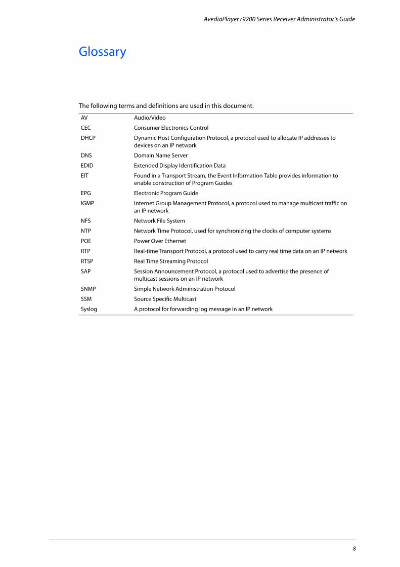
The following terms and definitions are used in this document:
AV Audio/Video
CEC Consumer Electronics Control
DHCP Dynamic Host Configuration Protocol, a protocol used to allocate IP addresses to devices on an IP network
DNS Domain Name Server
EDID Extended Display Identification Data
EIT Found in a Transport Stream, the Event Information Table provides information to enable construction of Program Guides
EPG Electronic Program Guide
IGMP Internet Group Management Protocol, a protocol used to manage multicast traffic on an IP network
NFS Network File System
NTP Network Time Protocol, used for synchronizing the clocks of computer systems
POE Power Over Ethernet
RTP Real-time Transport Protocol, a protocol used to carry real time data on an IP network
RTSP Real Time Streaming Protocol
SAP Session Announcement Protocol, a protocol used to advertise the presence of multicast sessions on an IP network
SNMP Simple Network Administration Protocol
SSM Source Specific Multicast
Syslog A protocol for forwarding log message in an IP network

AvediaPlayer r9200 Series Receiver Administrator’s Guide
About This Guide
This manual explains how to set up, use and manage Exterity AvediaPlayer r92xx Series Receivers.
Exterity AvediaPlayer Receivers make TV and video channels available to HD digital TVs and AV displays using a standard IP network. AvediaPlayer Receivers also integrate effortlessly with any Exterity IPTV solution and industry standard IPTV equipment.
AvediaPlayer DocumentationThis manual – the AvediaPlayer Receiver Administrator’s Guide – shows you how to configure the device to meet your specific requirements.
• Refer to the Installation Solutions Guide for information about installing the AvediaPlayer Receivers using the TV mounting plates, enclosures and fixtures available from Exterity.
• Refer to the AvediaPlayer r92xx Receivers Getting Started Guide for interconnection, basic configuration, and Regulatory and Safety information.
• Refer to the AvediaPlayer Receiver Remote Control Handset Administrator’s Guide for information about the configuration and use of the remote control handset.
All AvediaPlayer documentation is available in the Receivers tab at http://www.exterity.com/support/productdocs.html.
Additional DocumentationAdditional documentation describing customisation and addition of more languages to the displayed client interface, and the use of the RDK (Receiver Development Kit) are available on request from Exterity. Please contact your Exterity sales representative for more information.
Receiver Development Kit (RDK) The Receiver Development Kit (RDK) enables Exterity partners to create customised solutions using third-party applications such as middleware.
Third-party applications can control the Exterity receiver any or a combination of the following:
• The JavaScript API
• The Terminal Control Interface (TCI)
• The Simple Network Management Protocol (SNMP) interface
The JavaScript API gives programmers extensive control of the AvediaPlayer Receiver and also provides a mechanism for sending customised JavaScript events to the integrated browser. JavaScript programmers can also use Exterity extensions to access commonly-used functions such as changing channels, controlling volume, and video fast forwarding.
Contact your Exterity sales representative for availability of the Receiver Development Kit, Managed Information Base, and customisation documentation.
ScopeThis edition of the manual refers to version 3.4 of the AvediaPlayer r92xx Receivers and describes the configuration of the receivers using the Web Admin Interface.
AudienceThis manual is intended for use by systems integrators or systems administrators who are installing and setting up Exterity products.
It is assumed that readers are familiar with installing and configuring network-based products. Ideally, readers will also have an understanding of the key features of an IPTV system.
9
AvediaPlayer r9200 Series Receiver Administrator’s Guide
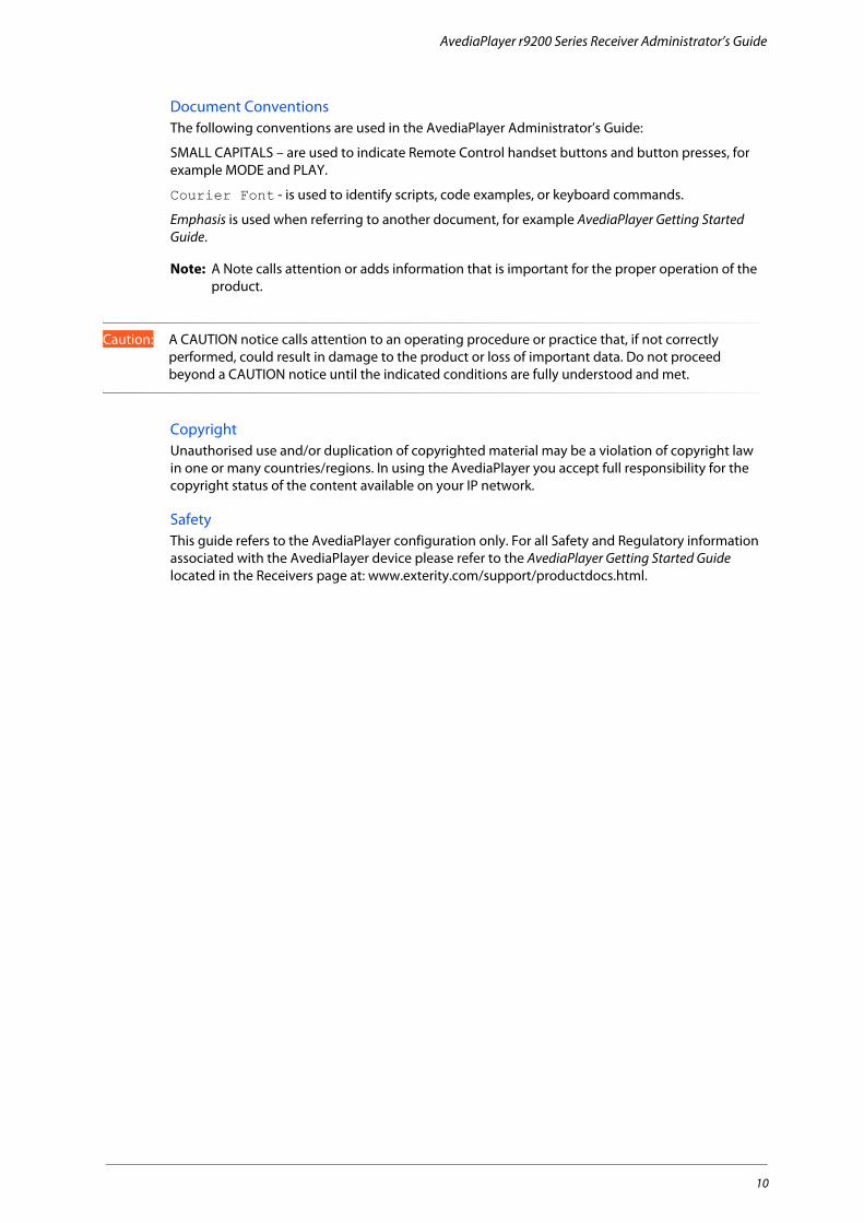
Document ConventionsThe following conventions are used in the AvediaPlayer Administrator’s Guide:
SMALL CAPITALS – are used to indicate Remote Control handset buttons and button presses, for example MODE and PLAY.
Courier Font - is used to identify scripts, code examples, or keyboard commands.
Emphasis is used when referring to another document, for example AvediaPlayer Getting Started Guide.
Note: A Note calls attention or adds information that is important for the proper operation of the product.
Caution: A CAUTION notice calls attention to an operating procedure or practice that, if not correctly performed, could result in damage to the product or loss of important data. Do not proceed beyond a CAUTION notice until the indicated conditions are fully understood and met.
CopyrightUnauthorised use and/or duplication of copyrighted material may be a violation of copyright law in one or many countries/regions. In using the AvediaPlayer you accept full responsibility for the copyright status of the content available on your IP network.
SafetyThis guide refers to the AvediaPlayer configuration only. For all Safety and Regulatory information associated with the AvediaPlayer device please refer to the AvediaPlayer Getting Started Guide located in the Receivers page at: www.exterity.com/support/productdocs.html.
10

1 Management Interfaces
There are three main ways to manage the AvediaPlayer Receiver:
• The Web Management Interface.
• The Admin Interface.
• The AvediaServer Director.
In addition, you can use any third-party SNMP tool to manage the receiver. Contact your reseller to obtain the Management Information Base (MIB). Alternatively, you can use the Terminal Control Interface (TCI), part of the Receiver Development Kit (RDK). Please see the Exterity Receivers Developer’s Guide for more information.
Web Management InterfaceYou can manage every aspect of the receiver’s functionality using its web management interface as follows:
1 Enter the IP address of the receiver in your browser or click the receiver’s name in the AvediaServer Director application.
2 When prompted, enter the correct username and password. The default login details are:
Username: admin
Password: labrador
Figure 1 AvediaPlayer login dialog
3 The web interface opens in your browser as shown in Figure 2.
If you cannot access the web interface, try to “ping” the receiver, telnet into it, or connect to it using the serial interface (see “Admin Interface” on page 13). If this is still unsuccessful, you can use the rear panel RESET button to reset the device. Please see “Using the Reset Button” on page 62 for more information.
Web Management Interface 11

AvediaPlayer r9200 Series Receiver Administrator’s Guide
Figure 2 AvediaPlayer web interface – General page
4 Click the menu items in the left panel to display the associated page in the right. Navigate through the menu, changing settings as required. Click Apply Changes on each page before navigating away from that page. A check mark appears on the button indicating the settings have been saved.
Note: You can control access to the web interface by changing the login. Refer to “Changing the Admin Password” in the AvediaPlayer r92xx Series Getting Started Guide.
Web Management Interface 12
AvediaPlayer r9200 Series Receiver Administrator’s Guide
Admin InterfaceIn certain circumstances it may not be possible to manage a receiver via its web interface. In these situations, you can access the receiver via a text based admin interface, which is available using:
• A terminal emulator program (such as PuTTY). This allows you to log into the receiver using:
• The serial interface (marked admin on the rear panel of the unit). See Appendix C, "Serial Admin Interface Connection" for details of how to connect to the serial admin port.
• Telnet
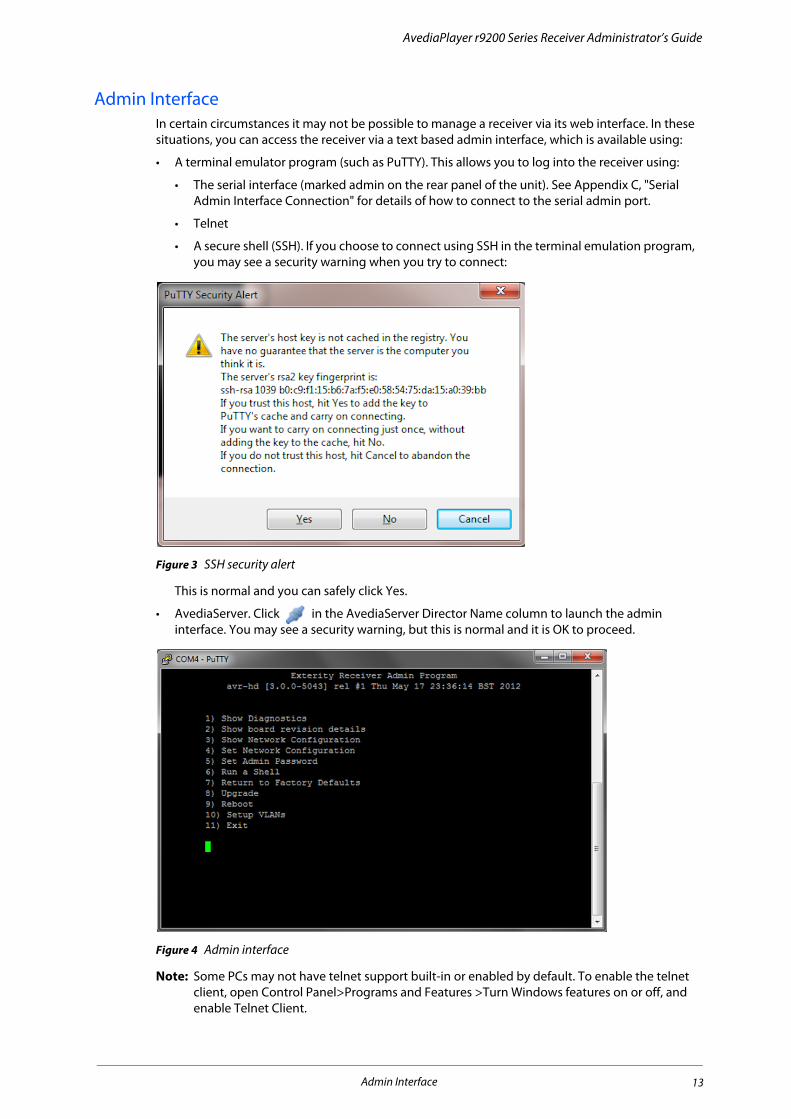
• A secure shell (SSH). If you choose to connect using SSH in the terminal emulation program, you may see a security warning when you try to connect:
Figure 3 SSH security alert
This is normal and you can safely click Yes.
• AvediaServer. Click in the AvediaServer Director Name column to launch the admin interface. You may see a security warning, but this is normal and it is OK to proceed.
Figure 4 Admin interface
Note: Some PCs may not have telnet support built-in or enabled by default. To enable the telnet client, open Control Panel>Programs and Features >Turn Windows features on or off, and enable Telnet Client.
Admin Interface 13

AvediaPlayer r9200 Series Receiver Administrator’s Guide
Once connected, log in using the username admin and password as for the web interface (default labrador).
Note: If the TV/ADM port has been configured for TV serial interface control, return it to the default admin mode by selecting the TV page and None from the TV Control Type drop-down list. If the web interface is unavailable, use the RESET button to set the mode back to its default.
AvediaServer Director The AvediaServer Director is an application used for device discovery and management and is an integral part of the AvediaServer. It uses SNMP to manage a subset of device functionality and can also be used to start the AvediaPlayer web interface. One of its main features is the ability to manage more than one device simultaneously. For example, you can make changes to one receiver, then use the Director application to apply the new settings to many receivers.
Refer to the AvediaServer Managing your IPTV System - Administrator’s Guide for more information about using the Director application.
AvediaServer Director 14

2 Basic Configuration
This chapter describes the basic configuration of the AvediaPlayer r92xx series receiver for use as an IPTV receiver and contains the following information:
• Setting Receiver Properties
• Specifying Front Panel LED Behaviour
• Static Channels
• VLAN Configuration (AvediaPlayer r9220 only)
IntroductionProvided the following basic network conditions are met, AvediaPlayer Receivers require no actual configuration to get them up and running and playing channels on a network.
The network:
• Must be DHCP-enabled. (The AvediaPlayer Receiver is set to DHCP by default.)
• Must have some channels being multicast.
• Must have active SAP announcements. (In its default setting, the AvediaPlayer Receiver listens for these announcements on the multicast address 239.255.255.255.)
• Must be IGMP-enabled.
This is the minimum configuration required to enable a client to view any available channel streams on a connected TV or display. In this configuration, interoperation with middleware (portals) or EPG generators is not expected or required.
This section assumes that the procedures described in the AvediaPlayer r92xx series Getting Started Guide have been completed successfully and that you know the AvediaPlayer Receiver IP address.
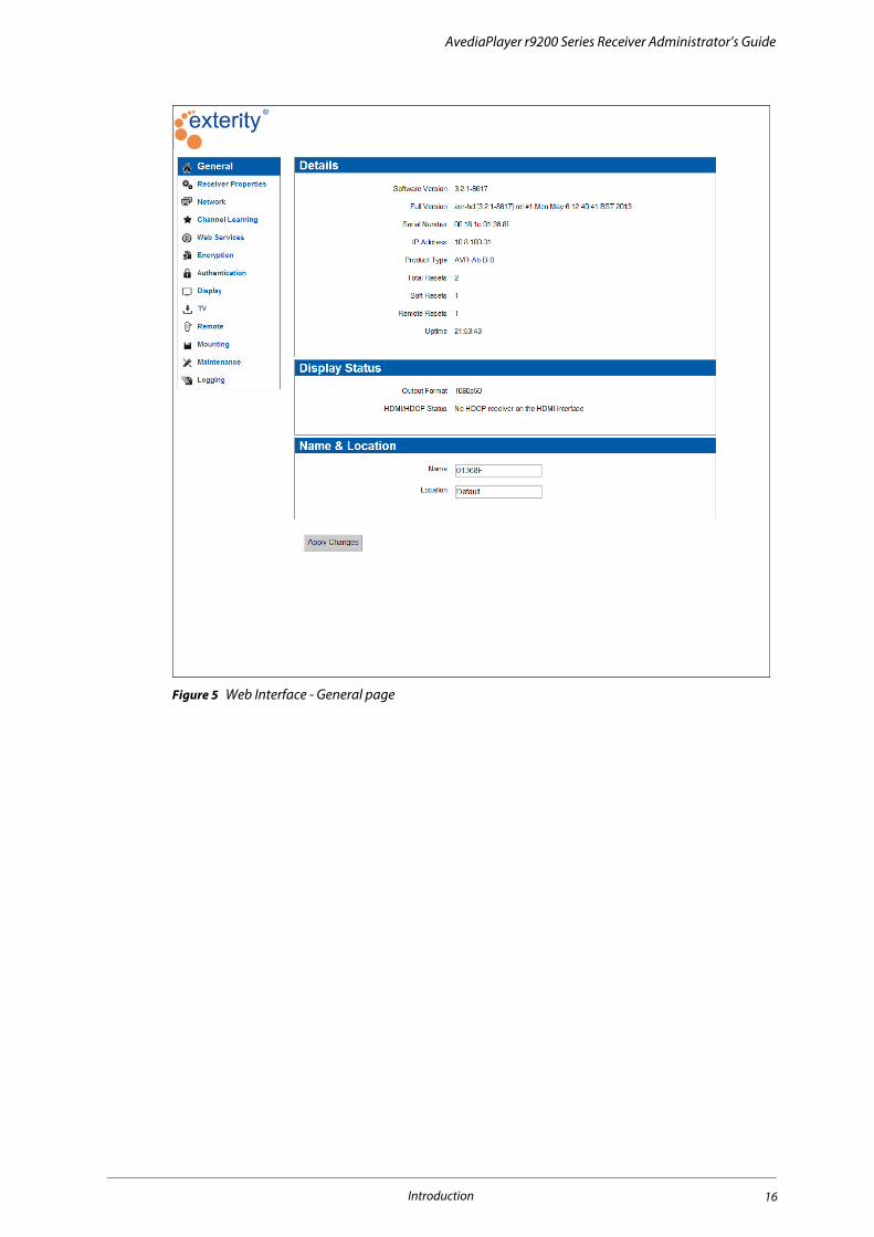
Confirm that you are connected to the required device by checking the device serial number and configure the name and location as shown in Figure 5.
Introduction 15
AvediaPlayer r9200 Series Receiver Administrator’s Guide
Figure 5 Web Interface - General page
Introduction 16
AvediaPlayer r9200 Series Receiver Administrator’s Guide
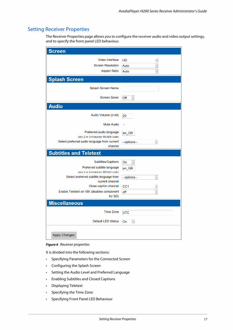
Setting Receiver PropertiesThe Receiver Properties page allows you to configure the receiver audio and video output settings, and to specify the front panel LED behaviour.
Figure 6 Receiver properties
It is divided into the following sections:
• Specifying Parameters for the Connected Screen
• Configuring the Splash Screen
• Setting the Audio Level and Preferred Language
• Enabling Subtitles and Closed Captions
• Displaying Teletext
• Specifying the Time Zone
• Specifying Front Panel LED Behaviour
Setting Receiver Properties 17

AvediaPlayer r9200 Series Receiver Administrator’s Guide
Specifying Parameters for the Connected Screen Outputs up to 1080p @50Hz, 59.94Hz and 60Hz are available from the HDMI port. Up to 1080i @50Hz, 59.94Hz and 60Hz is available from the r9210 component connectors.
When the receiver is connected to the TV/display using the HDMI interface, you can leave the Screen Resolution and Aspect Ratio settings at the default Auto value. EDID information from the TV/display is used to determine the optimum settings, and the receiver uses these values to configure its output. In some instances however, manual configuration may be required.
Output can be configured for 4:3 or widescreen displays.
Additional r9210 OutputsThe r9210 also supports SD output at 480i/576i 50/60Hz on the analogue Composite, S-Video and RGBS connections. Table 1 and Table 2 explain which connections are available:
Note: When the video interface is set to HD and Screen Resolution is Auto, 1080i is output from the Component connections. You must manually configure the Screen Resolution if a different output is required.
Note: In HD mode the r9210 outputs to both HDMI and Component connections at settings up to 1080i. If a setting of 1080p is manually chosen or is negotiated when set to Auto, only the HDMI output is available.
To specify the video interface:
1 Click Receiver Properties to display the page as shown in Figure 6.
2 Select SD or HD from the Video Interface drop-down list to suit the connected television or display.
3 Click Apply Changes.
If you have selected SD, skip the next step and continue on to Additional SD Settings. Otherwise proceed as follows:
To specify the screen resolution:
1 Click Receiver Properties to display the page as shown in Figure 6.
2 Click the Screen Resolution drop-down list and select 480p 60Hz, 576p 50Hz, 720p 60Hz, 720p 50Hz, 1080i 60Hz, 1080i 50Hz, 1080p 60Hz, 1080p 50Hz, or Auto to suit the connected television or display. You should use Auto unless you want to use a specific resolution and frame rate.
3 Select Auto from the Aspect Ratio drop-down list.
4 Click Apply Changes.
Table 1 Unencrypted content
HDMI Component Composite S-Video
SD No Yes Yes Yes
HD Yes, if HDCP authentication succeeded when encrypted content started playing. Otherwise No.
Yes No No
Table 2 Encrypted content
HDMI Component Composite S-Video
SD No No No No
HD Yes, if HDCP authentication succeeded when encrypted content started playing. Otherwise No.
No No
Setting Receiver Properties 18
AvediaPlayer r9200 Series Receiver Administrator’s Guide
Additional SD SettingsIf you selected SD you can configure the AvediaPlayer Receiver to output for a Normal (4:3) or Widescreen (16:9) connected television or display. When in SD mode and connected to a Normal (4:3) television or display, the Aspect Ratio setting controls how a widescreen signal is displayed. There are two options:
• Centre – Displays the centre of the widescreen image. The left and right outside margins of the picture are lost.
• Letterbox – Displays the complete widescreen image with black bars at top and bottom.
When a widescreen television or display is connected you can choose how 4:3 content is displayed. When displaying 4:3 content on a widescreen TV, Auto renders the content in the correct aspect ratio with black ‘curtains’ to either side of the picture. Selecting Force 16:9 stretches 4:3 content to fill the display.
To set the screen format and aspect ratio:
1 Click Receiver Properties to display the page as shown in Figure 6.
2 Select Normal or Widescreen from the Screen Resolution drop-down list.
• If you selected Normal, select Letter Box or Centre from the Aspect Ratio drop-down list.
• If you selected Widescreen, select Auto or Force 16:9 from the Aspect Ratio drop-down list.
3 Click Apply Changes.
When to use Force 16:9The Aspect Ratio setting Force 16:9 is provided to offer a choice of how 4:3 content is displayed on a widescreen TV. When displaying 4:3 content on a widescreen TV, Auto renders the content in the correct aspect ratio with black bars to either side of the picture. Selecting Force 16:9 stretches 4:3 content to fill the display.
Configuring the Splash ScreenAudio/Video is the default display mode for the AvediaPlayer Receiver power on process. You can specify an image to be used as a splash screen in the Current or Startup Mode on the Display page. If you do not specify an image, the Exterity default screen is displayed.
Splash Screen RequirementsAlternative images can be .jpg, .gif or .png file format. When creating a splash screen image for HD output, restrict the image to a resolution of 1280x720 pixels and a maximum of 32-bit colour quality. The maximum file size is 1MB.
The receiver uses TFTP to download new splash screen images from a TFTP server. To update the splash screen, first ensure that the correct TFTP server IP address is specified in the Maintenance page Settings section, and that the TFTP server is running.
• If the TFTP server is not running, you can only use the last uploaded image (or the default).
• If the file cannot be found, the default splash screen is used.
To specify the splash screen image:
1 Click Receiver Properties to display the page as shown in Figure 6.
2 Enter the name of the image file, including the file extension, into the Splash Screen Name field.
3 Click Apply Changes.
The splash screen file is now downloaded from the TFTP server. You can configure the splash screen to be displayed on startup, or immediately:
Setting Receiver Properties 19

AvediaPlayer r9200 Series Receiver Administrator’s Guide
To display the splash screen on startup:
1 Ensure you have uploaded the image file as described.
2 Click Display.
3 Select Splash Screen from the Startup Mode drop-down list.
4 Click Apply Changes.
To display the splash screen immediately:
1 Ensure you have uploaded the image file as described.
2 Click Display.
3 Select Splash Screen from the Current Mode drop-down list.
4 Click Apply Changes.
Setting the Audio Level and Preferred LanguageYou can set the level of audio volume output from the receiver. This is a value between 0 (min volume) and 40 (max volume). The default is 20. You can also turn off the audio output using the Mute Audio function. Audio is enabled by default.
Some TV channels have multiple audio streams in different languages. The receiver can be configured with a preferred audio and displayed text language. If a channel contains an audio stream of this language it is selected, otherwise the first language found is used.
To set the Audio Volume:
1 Click Receiver Properties to display the page as shown in Figure 6.
2 Enter a value between 0 and 40 in the Audio Volume field.
3 Click Apply Changes.
To mute the audio output:
1 Click Receiver Properties to display the page as shown in Figure 6.
2 Click the Mute Audio checkbox.
3 Click Apply Changes.
To set the preferred audio language:
1 Click Receiver Properties to display the page as shown in Figure 6.
2 In the Preferred audio language field, enter the two or three character ISO639 code for the language, or if the current channel has embedded language codes, select the required language from the Select preferred audio language from current channel drop-down list.
3 Click Apply Changes.
Refer to Chapter 8, "Configuring Remote Control Handsets" to set the volume, mute audio and specify text languages using the Exterity Remote Control handsets.
Setting Receiver Properties 20
AvediaPlayer r9200 Series Receiver Administrator’s Guide
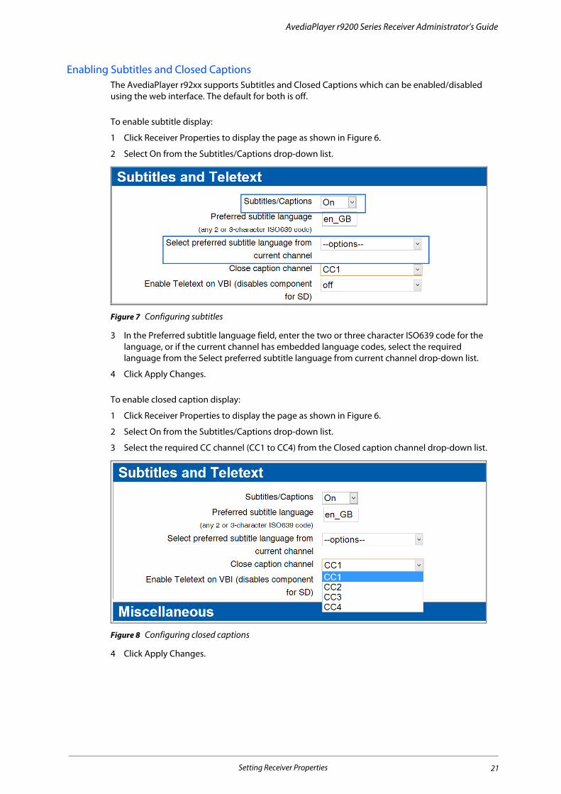
Enabling Subtitles and Closed Captions The AvediaPlayer r92xx supports Subtitles and Closed Captions which can be enabled/disabled using the web interface. The default for both is off.
To enable subtitle display:
1 Click Receiver Properties to display the page as shown in Figure 6.
2 Select On from the Subtitles/Captions drop-down list.
Figure 7 Configuring subtitles
3 In the Preferred subtitle language field, enter the two or three character ISO639 code for the language, or if the current channel has embedded language codes, select the required language from the Select preferred subtitle language from current channel drop-down list.
4 Click Apply Changes.
To enable closed caption display:
1 Click Receiver Properties to display the page as shown in Figure 6.
2 Select On from the Subtitles/Captions drop-down list.
3 Select the required CC channel (CC1 to CC4) from the Closed caption channel drop-down list.
Figure 8 Configuring closed captions
4 Click Apply Changes.
Setting Receiver Properties 21
AvediaPlayer r9200 Series Receiver Administrator’s Guide
Displaying TeletextAll AvediaPlayer r92xx receivers can decode Teletext pages when they are included in the selected channel and display them on the connected TV. No additional configuration is required. The AvediaPlayer r9210 composite output also supports Teletext (pass through) on the VBI (vertical blanking interval).
Teletext DecodingTeletext pages are accessed and displayed by pressing the TEXT button on the AvediaPlayer V5 Remote Control handset. The Audio Level and Mute controls operate as normal.
Note: To view Teletext pages using Exterity Remote Control Handsets V3 and V4, a customised handset file is required.
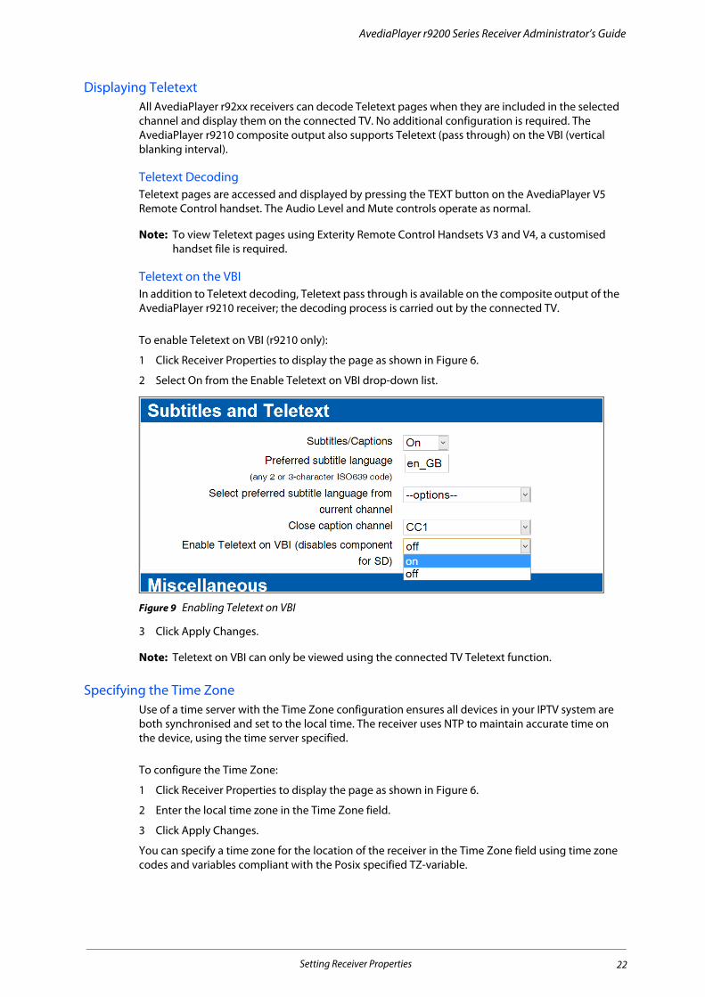
Teletext on the VBIIn addition to Teletext decoding, Teletext pass through is available on the composite output of the AvediaPlayer r9210 receiver; the decoding process is carried out by the connected TV.
To enable Teletext on VBI (r9210 only):
1 Click Receiver Properties to display the page as shown in Figure 6.
2 Select On from the Enable Teletext on VBI drop-down list.
Figure 9 Enabling Teletext on VBI
3 Click Apply Changes.
Note: Teletext on VBI can only be viewed using the connected TV Teletext function.
Specifying the Time ZoneUse of a time server with the Time Zone configuration ensures all devices in your IPTV system are both synchronised and set to the local time. The receiver uses NTP to maintain accurate time on the device, using the time server specified.
To configure the Time Zone:
1 Click Receiver Properties to display the page as shown in Figure 6.
2 Enter the local time zone in the Time Zone field.
3 Click Apply Changes.
You can specify a time zone for the location of the receiver in the Time Zone field using time zone codes and variables compliant with the Posix specified TZ-variable.
Setting Receiver Properties 22

AvediaPlayer r9200 Series Receiver Administrator’s Guide
For example, to specify GMT without daylight saving (British Summer Time), simply enter GMT and click Apply Changes. For locations west of the Prime Meridian you must add a positive offset. For locations east, add a negative offset. You can also specify daylight saving parameters, setting the time and the start/stop period.
Example 1: Specify Central European Time (CET) all yearCET time is 1 hour east of the Prime Meridian
1 Click Receiver Properties to display the page shown in Figure 6.
2 Enter CET-1 in the Time Zone field.
3 Click Apply Changes.
Example 2: Specify Eastern Standard Time (EST) with daylight saving:• Eastern Standard time is 5 hours west of the Prime Meridian
• Daylight saving begins on the first Sunday in April at 2:00am
• Daylight saving ends on the last Sunday in October at 2:00am
1 Click Receiver Properties to display the page shown in Figure 6.
2 Enter EST+5EDT,M0/2,M0/2 in the Time Zone field.
3 Click Apply Changes.
Specifying Front Panel LED BehaviourThe main LED on the front of the receiver can be configured to have default mode On or Off.
• If the default status is On, the LED pulses constantly, blinking in response to input from the Remote Control handset.
• If the default status is Off, the LED stays off, blinking only in response to input from the Remote control handset. The default value for this setting is On, pulsing.
To set the default LED status:
1 Click Receiver Properties to display the page as shown in Figure 6.
2 Select On or Off from the Default LED Status drop-down list.
3 Click Apply Changes.
Setting Receiver Properties 23
AvediaPlayer r9200 Series Receiver Administrator’s Guide
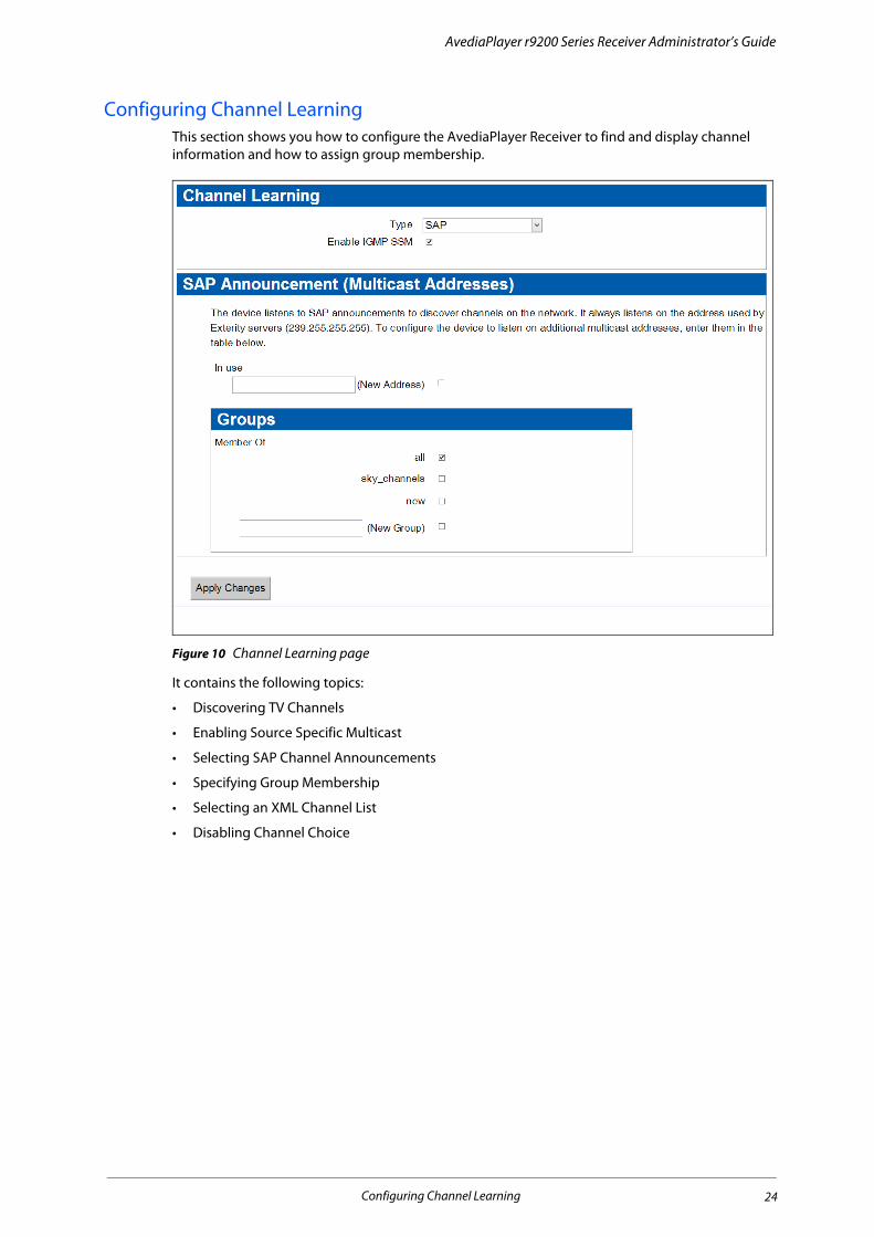
Configuring Channel LearningThis section shows you how to configure the AvediaPlayer Receiver to find and display channel information and how to assign group membership.
Figure 10 Channel Learning page
It contains the following topics:
• Discovering TV Channels
• Enabling Source Specific Multicast
• Selecting SAP Channel Announcements
• Specifying Group Membership
• Selecting an XML Channel List
• Disabling Channel Choice
Configuring Channel Learning 24
AvediaPlayer r9200 Series Receiver Administrator’s Guide
Discovering TV ChannelsThe receiver can use two mechanisms to build the list of channels: SAP (default) and XML.
• When SAP is selected, the channel list is built up from SAP (Session Announcement Protocol) announcements generated by Exterity Encoders, TV Gateways and other compatible products.
• When XML is selected, the channel list is created from the listing in an XML file downloaded by the receiver from a web server. To ensure the list is up to date, you can configure the receiver to download the file at specified intervals.
In some applications, such as digital signage or use with a portal, you may want to render the receiver unable to detect, and hence select, any other channels by selecting None in the Channel Learning menu.
Note: You can also specify content that is not announced using SAP or specified in an XML channel list. For more information refer to KB000295 Configuring Static Channels on r92xx Receivers.
Enabling Source Specific MulticastSource Specific Multicast (SSM) is supported by the AvediaPlayer r92xx receivers and can be enabled if required. SSM is an enhancement to IP multicast (defined in IGMP v3) and also requires support in your network switches. When enabled, the source and multicast address for each channel are listed in on the Display page. Source-specific multicast (SSM) allows delivery of multicast packets which are only those from a source address specified by the receiver. If IGMP V3 is not implemented on your network you cannot use SSM.
When enabling or disabling SSM, you must reboot the receiver to repeat the channel discovery process. The URI is specified in the form:
scheme://[source@]address:port
for example:
udp://[email protected]:5000
To enable source specific multicast:
1 Click Channel Learning to display the Channel Learning page as shown in Figure 10.
2 Click the Enable IGMP SSM checkbox.
3 Click Apply Changes.
4 Click Maintenance and select Reboot from the Operation drop-down list.
5 Click Apply Changes.
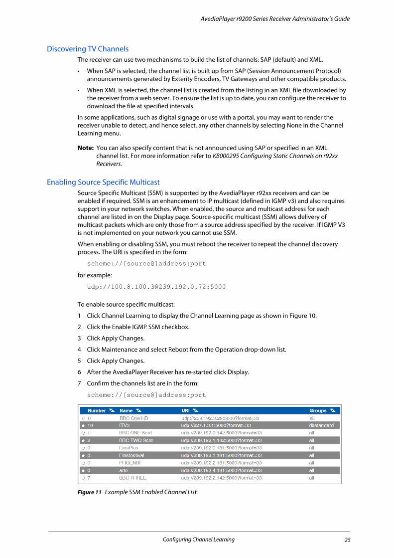
6 After the AvediaPlayer Receiver has re-started click Display.
7 Confirm the channels list are in the form:
scheme://[source@]address:port
Figure 11 Example SSM Enabled Channel List
Configuring Channel Learning 25
AvediaPlayer r9200 Series Receiver Administrator’s Guide
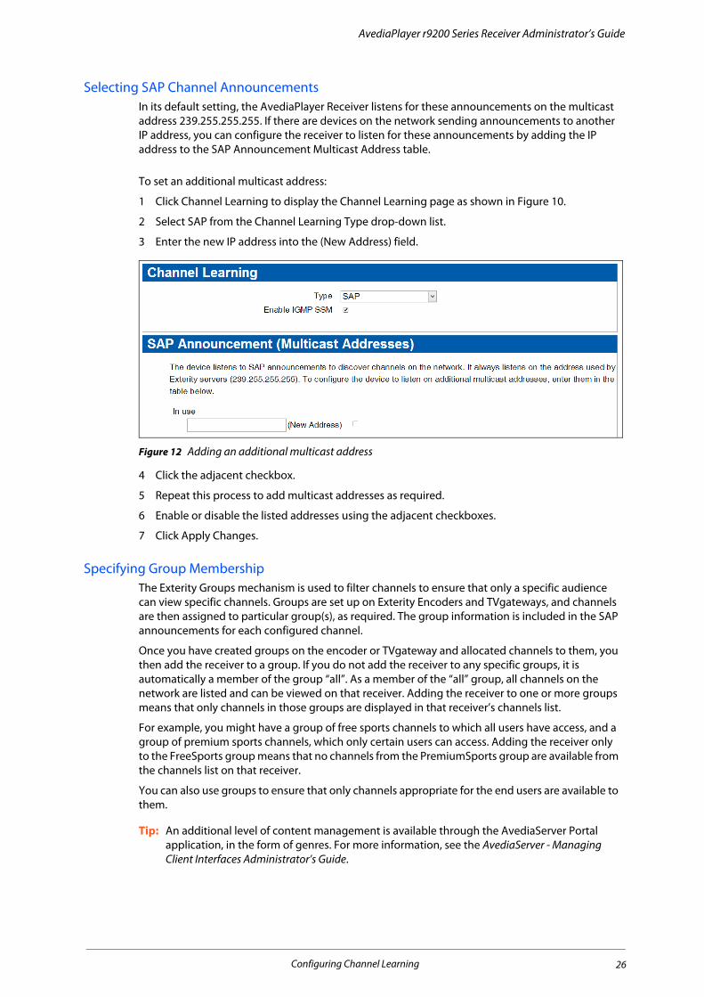
Selecting SAP Channel AnnouncementsIn its default setting, the AvediaPlayer Receiver listens for these announcements on the multicast address 239.255.255.255. If there are devices on the network sending announcements to another IP address, you can configure the receiver to listen for these announcements by adding the IP address to the SAP Announcement Multicast Address table.
To set an additional multicast address:
1 Click Channel Learning to display the Channel Learning page as shown in Figure 10.
2 Select SAP from the Channel Learning Type drop-down list.
3 Enter the new IP address into the (New Address) field.
Figure 12 Adding an additional multicast address
4 Click the adjacent checkbox.
5 Repeat this process to add multicast addresses as required.
6 Enable or disable the listed addresses using the adjacent checkboxes.
7 Click Apply Changes.
Specifying Group MembershipThe Exterity Groups mechanism is used to filter channels to ensure that only a specific audience can view specific channels. Groups are set up on Exterity Encoders and TVgateways, and channels are then assigned to particular group(s), as required. The group information is included in the SAP announcements for each configured channel.
Once you have created groups on the encoder or TVgateway and allocated channels to them, you then add the receiver to a group. If you do not add the receiver to any specific groups, it is automatically a member of the group “all”. As a member of the “all” group, all channels on the network are listed and can be viewed on that receiver. Adding the receiver to one or more groups means that only channels in those groups are displayed in that receiver’s channels list.
For example, you might have a group of free sports channels to which all users have access, and a group of premium sports channels, which only certain users can access. Adding the receiver only to the FreeSports group means that no channels from the PremiumSports group are available from the channels list on that receiver.
You can also use groups to ensure that only channels appropriate for the end users are available to them.
Tip: An additional level of content management is available through the AvediaServer Portal application, in the form of genres. For more information, see the AvediaServer - Managing Client Interfaces Administrator’s Guide.
Configuring Channel Learning 26
AvediaPlayer r9200 Series Receiver Administrator’s Guide
Figure 13 Groups page
To add the receiver to a channel group:
1 Click Channel Learning to display the page as shown in Figure 10.
2 In the Groups panel:
• Select a previously configured group by clicking the associated checkbox or,
• Enter a new group name in the New Group field and click the adjacent checkbox.
3 Click Apply Changes.
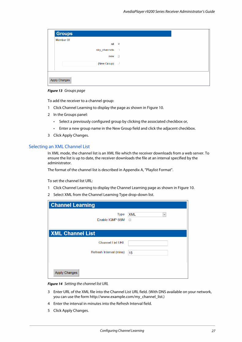
Selecting an XML Channel List In XML mode, the channel list is an XML file which the receiver downloads from a web server. To ensure the list is up to date, the receiver downloads the file at an interval specified by the administrator.
The format of the channel list is described in Appendix A, "Playlist Format".
To set the channel list URL:
1 Click Channel Learning to display the Channel Learning page as shown in Figure 10.
2 Select XML from the Channel Learning Type drop-down list.
Figure 14 Setting the channel list URL
3 Enter URL of the XML file into the Channel List URL field. (With DNS available on your network, you can use the form http://www.example.com/my_channel_list.)
4 Enter the interval in minutes into the Refresh Interval field.
5 Click Apply Changes.
Configuring Channel Learning 27

AvediaPlayer r9200 Series Receiver Administrator’s Guide
Disabling Channel ChoiceYou can deselect channel learning where there is no requirement to select from channels discovered by the AvediaPlayer Receiver. This can be useful if channel availability is to be controlled by a portal, or the AvediaPlayer Receiver is to be used in a digital signage application. When disabled, you must specify the AvediaPlayer Receiver display mode and the URI of the content. Refer to “Simultaneously Specifying Mode and Content” on page 37 for more information.
Channel Learning is enabled by default.
To disable channel learning:
1 If the content you want to display is not a currently streaming channel continue from Step 4, otherwise first select the channel.
2 Click Display and select the required channel from the Current Channel list.
3 Click Change Channel.
4 Click Channel Learning in the menu on the left.
5 Select None from the Channel Learning Type drop-down list.
Figure 15 Disabling channel learning
6 Click Apply Changes.
When Channel Learning is disabled no channels are listed on the Display page and the AvediaPlayer Receiver does not respond to Remote Control handset Channel +/- or button presses.
Note: If re-enabling channel learning, the channel list is re-populated as each announcement is received. You may need to refresh your browser until the channel list is fully rebuilt.
Static ChannelsA static channel is a way of making content available independently of other IPTV system content and the channel learning processes.
For example, you may want to:
• Include some files held on local/remote storage devices and include them in the channel listing.
• Include content from a source that does not use SAP to announce the presence of the channel.
• Add a channel but hide its listing from the Program Guide displayed on the connected TV.
The procedures required are beyond the scope of this guide but are detailed in an Exterity Knowledge Base article. Ask your Exterity representative for KB000295 Configuring Static Channels on r92xx Receivers.
Static Channels 28
AvediaPlayer r9200 Series Receiver Administrator’s Guide
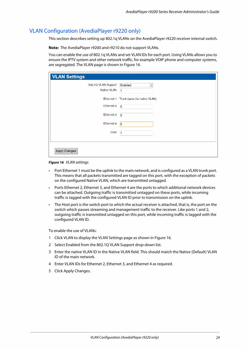
VLAN Configuration (AvediaPlayer r9220 only)This section describes setting up 802.1q VLANs on the AvediaPlayer r9220 receiver internal switch.
Note: The AvediaPlayer r9200 and r9210 do not support VLANs.
You can enable the use of 802.1q VLANs and set VLAN IDs for each port. Using VLANs allows you to ensure the IPTV system and other network traffic, for example VOIP phone and computer systems, are segregated. The VLAN page is shown in Figure 16.
Figure 16 VLAN settings
• Port Ethernet 1 must be the uplink to the main network, and is configured as a VLAN trunk port. This means that all packets transmitted are tagged on this port, with the exception of packets on the configured Native VLAN, which are transmitted untagged.
• Ports Ethernet 2, Ethernet 3, and Ethernet 4 are the ports to which additional network devices can be attached. Outgoing traffic is transmitted untagged on these ports, while incoming traffic is tagged with the configured VLAN ID prior to transmission on the uplink.
• The Host port is the switch port to which the actual receiver is attached, that is, the port on the switch which passes streaming and management traffic to the receiver. Like ports 1 and 2, outgoing traffic is transmitted untagged on this port, while incoming traffic is tagged with the configured VLAN ID.
To enable the use of VLANs:
1 Click VLAN to display the VLAN Settings page as shown in Figure 16.
2 Select Enabled from the 802.1Q VLAN Support drop-down list.
3 Enter the native VLAN ID in the Native VLAN field. This should match the Native (Default) VLAN ID of the main network.
4 Enter VLAN IDs for Ethernet 2, Ethernet 3, and Ethernet 4 as required.
5 Click Apply Changes.
VLAN Configuration (AvediaPlayer r9220 only) 29

3 Selecting Channels
This chapter contains the following sections:
• Selecting Channels with the Web Management Interface
• Selecting a Channel from the List
• Handling Encrypted Content
• SecureMedia Configuration
Streamed TV and radio channels can be selected for display on the connected TV or display by using the Remote Control handset to choose a TV or radio channel, or by the system administrator. Note that, without further configuration, the user can only choose from the streamed TV and radio channels.
Selecting Channels with the Web Management InterfaceThe Display page contains three sections which allow you to control the content displayed on the connected television or display.
• Display enables configuration of the startup and current display mode.
• URLs allow you to specify a web page to be displayed when in browser mode, and you can select a channel from the Current Channel list to be played when in AV mode.
• You can also change the display mode and content at the same time using the required syntax in the Current Channel entry field.
While in Audio/Video mode you can change the channel by selecting one of the channels in the list. To order the channels, click the Number, Name, URI or Group column headings. Click a heading again to reverse the order.
Click Display to open the page as shown in Figure 17. Any configuration changes made are applied immediately when you click Change Channel or Apply Changes.
For example, you can change the current channel or temporarily override the web page being displayed.
Selecting Channels with the Web Management Interface 30
AvediaPlayer r9200 Series Receiver Administrator’s Guide
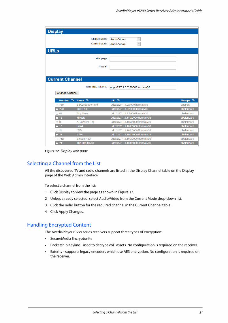
Figure 17 Display web page
Selecting a Channel from the ListAll the discovered TV and radio channels are listed in the Display Channel table on the Display page of the Web Admin Interface.
To select a channel from the list:
1 Click Display to view the page as shown in Figure 17.
2 Unless already selected, select Audio/Video from the Current Mode drop-down list.
3 Click the radio button for the required channel in the Current Channel table.
4 Click Apply Changes.
Handling Encrypted ContentThe AvediaPlayer r92xx series receivers support three types of encryption:
• SecureMedia Encryptonite
• Packetship Keyline - used to decrypt VoD assets. No configuration is required on the receiver.
• Exterity - supports legacy encoders which use AES encryption. No configuration is required on the receiver.
Selecting a Channel from the List 31
AvediaPlayer r9200 Series Receiver Administrator’s Guide
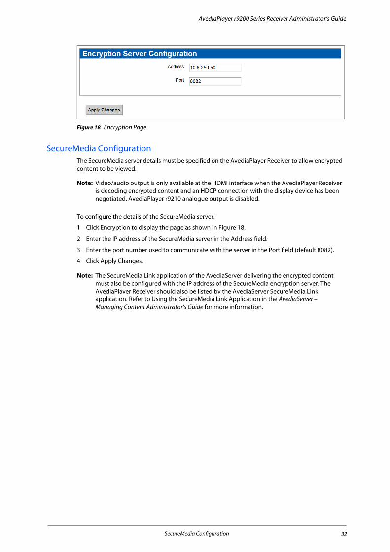
Figure 18 Encryption Page
SecureMedia ConfigurationThe SecureMedia server details must be specified on the AvediaPlayer Receiver to allow encrypted content to be viewed.
Note: Video/audio output is only available at the HDMI interface when the AvediaPlayer Receiver is decoding encrypted content and an HDCP connection with the display device has been negotiated. AvediaPlayer r9210 analogue output is disabled.
To configure the details of the SecureMedia server:
1 Click Encryption to display the page as shown in Figure 18.
2 Enter the IP address of the SecureMedia server in the Address field.
3 Enter the port number used to communicate with the server in the Port field (default 8082).
4 Click Apply Changes.
Note: The SecureMedia Link application of the AvediaServer delivering the encrypted content must also be configured with the IP address of the SecureMedia encryption server. The AvediaPlayer Receiver should also be listed by the AvediaServer SecureMedia Link application. Refer to Using the SecureMedia Link Application in the AvediaServer – Managing Content Administrator’s Guide for more information.
SecureMedia Configuration 32

4 Authentication
This chapter contains the following sections:
• Configuring Authentication
• Configuring the SNMP Agent
• Configuring an SNMP Trap Manager
The system administrator can specify which users can access the web interface pages. They can also enable or disable the SNMP agent, and configure community settings.
Configuring AuthenticationThe Authentication section allows you to specify which users can access the web interface pages.
Figure 19 Authentication web page
To allow all logged-in users to access the web interface pages:
1 Click Authentication to display the page as shown in Figure 19.
2 Select All Users.
3 Click Apply Changes.
To allow only authorised users to access the web interface pages:
1 Click Authentication to display the page as shown in Figure 19.
2 Select Authorised Users.
3 Specify the password that authorised users must enter to access the web pages.
4 Click Apply Changes.
Configuring Authentication 33

AvediaPlayer r9200 Series Receiver Administrator’s Guide
Configuring the SNMP AgentThe SNMP Agent section allows you to specify whether or not the receiver acts as an SNMP Agent.
Note: To specify an SNMP Trap Manager on your network, please see “Configuring an SNMP Trap Manager” on page 34.
To specify the device’s SNMP Agent status:
1 Click Authentication to display the page as shown in Figure 19.
2 In the SNMP Agent section, check the box to enable the SNMP Agent, or leave unchecked to disable.
3 If enabled, enter the required read/write and read-only community strings in the appropriate boxes.
4 Click Apply Changes.
Note: If the SNMP Agent is disabled, no SNMP Traps are sent by the receiver. This means that Exterity Management tools (for example, the Director application) will be unable to detect the device on the network.
Configuring an SNMP Trap ManagerSNMP traps are mainly used as device discovery messages; they enable Exterity’s management applications to discover devices on the network. These traps are always broadcast to 255.255.255.255. They are also transmitted to an additional configurable destination. By default, this is the multicast address 239.255.255.255, but this can be reconfigured to any broadcast, multicast or unicast destination as required.
If your network has an SNMP Trap Manager, enter its IP address here.
Configuring the SNMP Agent 34
5 Using Display Modes
This chapter contains the following information:
• Display Modes
• Setting the Startup Mode
• Setting the Current Mode
• Displaying a Web Page
• Playing a Playlist
• Simultaneously Specifying Mode and Content
Audio/Video is the default mode for the AvediaPlayer Receiver. The system administrator can also configure any additional functions available from the IP network, including middleware such as the AvediaServer Portal and EPG applications and internet access via the built-in web browser. Any display mode, except Off, can be configured as the power-on default and when returning from standby.
It can also be configured to play content in the form of a playlist held in either local (USB) or remote mounted locations. Refer to Appendix A, "Playlist Format" and to Chapter 11, "Using External Storage Devices" for more information.
Display ModesThe Display section of the Display web page allows you to configure both the startup display mode for the AvediaPlayer Receiver and the current mode.
Various display modes are defined as follows:
• Off: turns off all audio/video outputs to the television or display (Not available as a startup mode).
• Audio/Video: plays selected TV and Radio channels (default).
• Web Browser: runs the ANT Galio browser, displaying the web page specified in the Webpage field of the URLs section. If left blank, the Homepage configured on the Web Services page is displayed. Refer to “Specifying a Homepage” on page 51 for more information.
• Splash Screen: displays the specified splash screen (configured on the Receiver Properties page). Refer to “Configuring the Splash Screen” on page 19 for more information.
• Playlist: plays back the files in the configured playlist. Refer to Appendix A, "Playlist Format" for more information.
• EPG: displays the program guide from the Exterity EPG server (configured on the Web Services page. Refer to “Specifying an EPG” on page 52 for more information.
Display Modes 35

AvediaPlayer r9200 Series Receiver Administrator’s Guide
Setting the Startup ModeStartup mode is applied when the receiver is powering on, rebooting, or returning from standby. The available options are: Audio/Video, Web Browser, Splash Screen, Playlist and EPG. The default is Audio/Video.
To set the startup display mode:
1 Click Display to display the page as shown in Figure 17.
2 Select Audio/Video, Web Browser, Splash Screen, Playlist or EPG from the Startup Mode drop-down list.
3 Click Apply Changes.
Setting the Current ModeYou can control the current mode of operation. The available options are: Off, Audio/Video, Web Browser, Splash Screen, Playlist and EPG. The default is Audio/Video. You can use the current mode setting to override the current display.
To set the current display mode:
1 Click Display to display the page as shown in Figure 17.
2 In the Display section, click the Current Mode drop-down list to select Off, Audio/Video, Web Browser, Splash Screen, Playlist or EPG.
3 Click Apply Changes. The output to the connected TV or display is updated.
To regain control of the television or display using the Remote Control handset, press the TV button.
Displaying a Web PageWhile in browser mode, you can use the web management interface to navigate the browser to a particular page, overriding the home page.
To display a web page:
1 Click Display to display the page as shown in Figure 17.
2 In the URLs section, enter a URL into the Webpage field.
3 Select Web Browser from the Current Mode drop-down list in the Display section.
4 Click Apply Changes to display the selected webpage on the connected television or display.
Note: This field is cleared after the changes are applied. Subsequent Web Browser Display Mode changes display the Homepage (if configured in the Browser section of the Web Services page).
To regain control of the television or display using the Remote Control handset, press the TV button.
Setting the Startup Mode 36

AvediaPlayer r9200 Series Receiver Administrator’s Guide
Playing a PlaylistIn playlist mode, the AvediaPlayer Receiver plays the files specified in the playlist file. The playlist file can be hosted on a local (USB) storage device or a web server. To configure the receiver to run a playlist, you must specify the URL of the playlist. For the format of the playlist file, refer to Appendix A, "Playlist Format". Refer to Chapter 11, "Using External Storage Devices" for more information about configuring storage.
Note: To ensure smooth playback of a playlist, you should ensure that each item in the playlist requires the same codec and that the frame rate is the same whenever possible. Re-configuration during playback caused by dissimilar content can result in periods of no output on the client display.
To select a playlist:
1 Click Display to display the page as shown in Figure 17.
2 In the URLs section, enter the URL of your playlist into the Playlist field. (The example in Figure 20 shows the URL of a playlist in the mounted USB storage device.)
3 Select Playlist from the Current Mode drop-down list in the Display section.
Figure 20 Playlist in local USB storage device
4 Click Apply Changes to play the specified playlist.
To regain control of the television or display using the Remote Control handset, press the TV button.
Simultaneously Specifying Mode and Content You can change the display mode and displayed content by specifying both in the Current Channel entry field. This can be useful, for example when configuring a static channel, allowing you to specify a different mode as part of the channel parameters. (Refer to “Static Channels” on page 28 for more information.) To do this, you must specify the Mode and URI in the form:
mode:scheme://[uri]
for example:
media:file:///mnt/usb/sda1/samplemedia.ts
where mode is one of the following:
• browser – use browser to change the display mode to use the web browser and display the content specified by the URI. For example:
• browser:http://www.mywebpage.html changes the display mode to Browser and shows the web page specified in the URI
• browser:http://www.mypicturepage.com/image.jpg changes the display mode to Browser and shows an image specified in the URI in the browser
Playing a Playlist 37

AvediaPlayer r9200 Series Receiver Administrator’s Guide
• media – use media to change the display mode to Audio/Video and display the content specified by the URI. For example:
• media:udp://239.192.0.72:5000 changes the display mode to Audio/Video and displays a multicast stream specified in the URI.
• media:file:///mnt/usb/sda1/samplemedia.ts changes the display mode to Audio/Video and plays a transport stream from a mounted drive location specified in the URI.
• playlist – use playlist to change the display mode to Playlist and play the content specified in the playlist URI. For example:
• playlist: http://10.8.90.7/playlists/welcomeplaylist changes the display mode to Playlist and plays the content listed from a web server specified in the URI.
• playlist:/mnt/usb/sda1/myplaylist changes the display mode to Playlist and plays the list at a location specified in the URI.
Simultaneously Specifying Mode and Content 38
6 Configuring TV Control
This chapter contains the following information:
• Using the Serial Control Interface
• Using the Consumer Electronics Control (CEC) Interface
You can control some functions of compatible TVs using the AvediaPlayer Receiver Serial Control Interface (additional cable required) or using the Consumer Electronics Control (CEC) facility over the HDMI interface.
This enables the use of a single Remote Control handset to control both AvediaPlayer Receiver and TV functions. Control of both AvediaPlayer Receiver and TVs over the IP network also allows system administrators to manage receiver/display combinations.
Using the Serial Control InterfaceYou can configure the receiver to communicate with the attached TV/Display over the Serial TV interface. You can specify that it should send commands to the TV on entering and exiting standby mode (whether via Remote Control handset or management interface), thus powering on/off the TV as appropriate. An additional cable is required to connect the AvediaPlayer Receiver Serial port (RJ45 connector) to the TV control port. Connection details are described in Appendix D, "Serial TV Interface Connection".
In order to use this feature, contact your Exterity supplier to obtain a serial configuration file for your TV (a list of supported TV types is also available from your supplier).
Note: When the TV/ADM port is configured for use with a TV serial interface it cannot be used to access the Admin Interface.
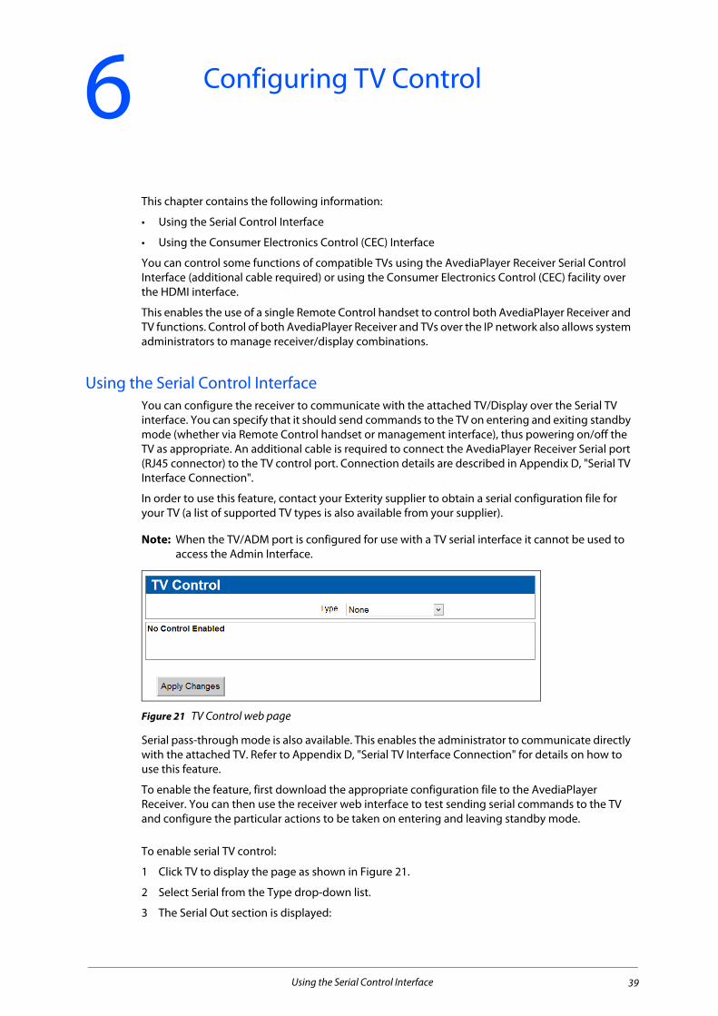
Figure 21 TV Control web page
Serial pass-through mode is also available. This enables the administrator to communicate directly with the attached TV. Refer to Appendix D, "Serial TV Interface Connection" for details on how to use this feature.
To enable the feature, first download the appropriate configuration file to the AvediaPlayer Receiver. You can then use the receiver web interface to test sending serial commands to the TV and configure the particular actions to be taken on entering and leaving standby mode.
To enable serial TV control:
1 Click TV to display the page as shown in Figure 21.
2 Select Serial from the Type drop-down list.
3 The Serial Out section is displayed:
Using the Serial Control Interface 39
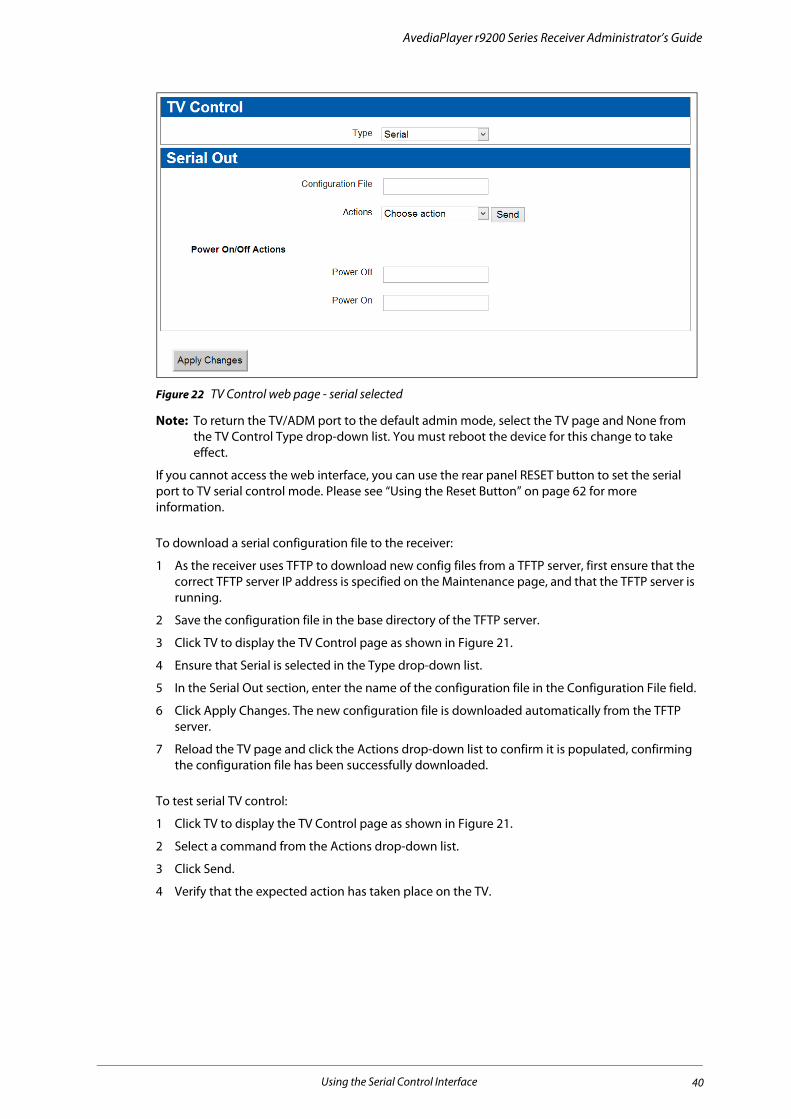
AvediaPlayer r9200 Series Receiver Administrator’s Guide
Figure 22 TV Control web page - serial selected
Note: To return the TV/ADM port to the default admin mode, select the TV page and None from the TV Control Type drop-down list. You must reboot the device for this change to take effect.
If you cannot access the web interface, you can use the rear panel RESET button to set the serial port to TV serial control mode. Please see “Using the Reset Button” on page 62 for more information.
To download a serial configuration file to the receiver:
1 As the receiver uses TFTP to download new config files from a TFTP server, first ensure that the correct TFTP server IP address is specified on the Maintenance page, and that the TFTP server is running.
2 Save the configuration file in the base directory of the TFTP server.
3 Click TV to display the TV Control page as shown in Figure 21.
4 Ensure that Serial is selected in the Type drop-down list.
5 In the Serial Out section, enter the name of the configuration file in the Configuration File field.
6 Click Apply Changes. The new configuration file is downloaded automatically from the TFTP server.
7 Reload the TV page and click the Actions drop-down list to confirm it is populated, confirming the configuration file has been successfully downloaded.
To test serial TV control:
1 Click TV to display the TV Control page as shown in Figure 21.
2 Select a command from the Actions drop-down list.
3 Click Send.
4 Verify that the expected action has taken place on the TV.
Using the Serial Control Interface 40

AvediaPlayer r9200 Series Receiver Administrator’s Guide
To configure actions to take on entering/exiting standby mode:
1 Click TV to display the TV Control page as shown in Figure 21.
2 Enter the appropriate actions in the Power On Actions and Power Off Actions fields. These should be commands as shown in the Test Serial Out drop-down. Multiple commands must be separated with a semicolon (;). If a delay is required between commands, use “sleep” followed by a value in seconds, for example, “tv_on;sleep 2;tv_mute_on”.
3 Click Apply Changes.
Using the Consumer Electronics Control (CEC) InterfaceYou can control a limited range of TVs (certain Sony, Toshiba and Philips models) using CEC over the HDMI interface. Using CEC, the on/standby state and volume level can be controlled without additional cabling between the AvediaPlayer Receiver and the TV. When configured, the Exterity Remote Control handset controls volume on the TV, and the On/Standby functions of both the TV and the AvediaPlayer Receiver.
To enable CEC TV control:
1 Click TV to display the page as shown in Figure 23.
2 Select CEC from the Type drop-down list. The CEC Options section is displayed:
Figure 23 CEC options
3 Click the CEC Options checkboxes for the required control functions.
4 Click Apply Changes.
When configured, the AvediaPlayer Receiver and TV behave as follows:
• Standby – When switching to standby mode, the receiver sends a CEC standby message to the connected TV before disabling the HDMI connection and entering standby mode. When returning from standby the AvediaPlayer Receiver enables the HDMI connection before sending the ‘on’ command to the TV.
• Volume – The remote handset volume controls are applied to the TV.
Note: When the CEC Volume option is selected, volume can only be changed using the remote control, not on the Receiver Properties page. However, if you select Mute Audio on the Receiver Properties page, or press Mute on the handset, this is applied only to the receiver, not to the TV.
Using the Consumer Electronics Control (CEC) Interface 41
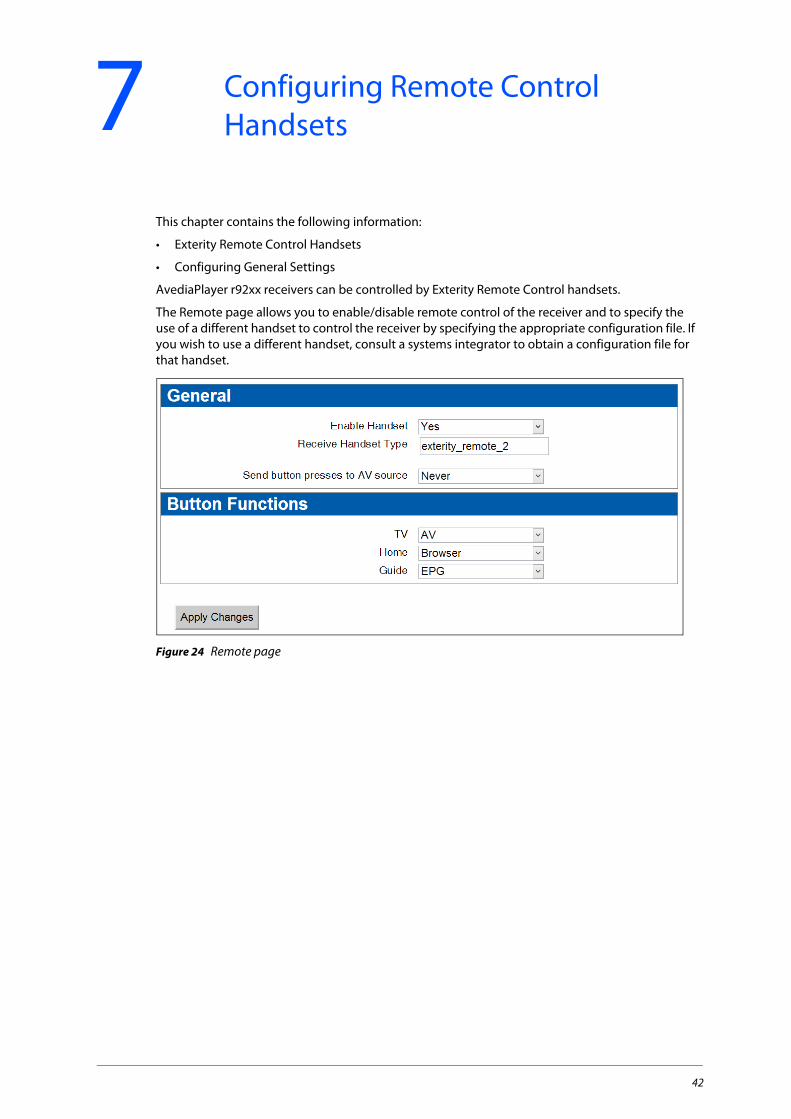
7 Configuring Remote Control Handsets
This chapter contains the following information:
• Exterity Remote Control Handsets
• Configuring General Settings
AvediaPlayer r92xx receivers can be controlled by Exterity Remote Control handsets.
The Remote page allows you to enable/disable remote control of the receiver and to specify the use of a different handset to control the receiver by specifying the appropriate configuration file. If you wish to use a different handset, consult a systems integrator to obtain a configuration file for that handset.
Figure 24 Remote page
42
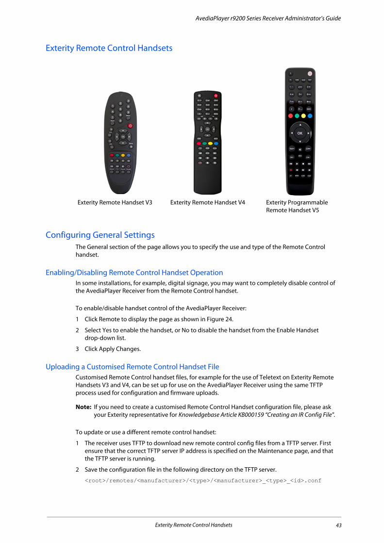
AvediaPlayer r9200 Series Receiver Administrator’s Guide
Exterity Remote Control Handsets
Configuring General SettingsThe General section of the page allows you to specify the use and type of the Remote Control handset.
Enabling/Disabling Remote Control Handset OperationIn some installations, for example, digital signage, you may want to completely disable control of the AvediaPlayer Receiver from the Remote Control handset.
To enable/disable handset control of the AvediaPlayer Receiver:
1 Click Remote to display the page as shown in Figure 24.
2 Select Yes to enable the handset, or No to disable the handset from the Enable Handset drop-down list.
3 Click Apply Changes.
Uploading a Customised Remote Control Handset FileCustomised Remote Control handset files, for example for the use of Teletext on Exterity Remote Handsets V3 and V4, can be set up for use on the AvediaPlayer Receiver using the same TFTP process used for configuration and firmware uploads.
Note: If you need to create a customised Remote Control Handset configuration file, please ask your Exterity representative for Knowledgebase Article KB000159 “Creating an IR Config File".
To update or use a different remote control handset:
1 The receiver uses TFTP to download new remote control config files from a TFTP server. First ensure that the correct TFTP server IP address is specified on the Maintenance page, and that the TFTP server is running.
2 Save the configuration file in the following directory on the TFTP server.
<root>/remotes/<manufacturer>/<type>/<manufacturer>_<type>_<id>.conf
Exterity Remote Handset V3 Exterity Remote Handset V4 Exterity Programmable Remote Handset V5
Exterity Remote Control Handsets 43

AvediaPlayer r9200 Series Receiver Administrator’s Guide
For example:
<root>/remotes/sony/dvd/sony_conf
3 Click Remote to display the page as shown in Figure 24.
4 Enter the name of the configuration file in the Receiver Handset Type field.
5 Click Apply Changes.
The new configuration file is downloaded automatically from the TFTP server. You can confirm the successful download by opening the log file as described in “Setting Up Logging” on page 65 and checking for completed TFTP activity.
Enabling Remote AV Device ControlIn addition to controlling on-screen menus, you can use the remote control handset to control an AV device attached to an Exterity encoder.
Figure 25 How remote AV device control works
Note: Please ensure that the encoder you are using is able to accept remote IR connections, and that it is set up with the appropriate IR configuration file, to allow it to send IR commands to the attached device.
To enable permanent remote AV device control:
1 Click Remote to display the page as shown in Figure 24.
2 Select Always from the Send button presses to AV source drop-down list.
3 Click Apply Changes.
When this mode is selected, every button press on the remote control applies to the AV device connected to the encoder. The remote control provides no access to streams on the receiver; you can however access some settings on the local receiver, by pressing the MODE button on the remote control. This button provides access to the following:
• Language - Select the language that the menu items appear in, (not the audio track).
• Audio – Select an audio track, if there is more than one.
• Subtitles – Turn subtitles on or off and select a subtitle track if there is one.
• Display – Displays the current TV resolution.
• Network - Displays IP address/network mask/gateway information.
• Remote Mode – Displays the current mode (AV source).
• Device Info - Displays information, such as software version.
Configuring General Settings 44

AvediaPlayer r9200 Series Receiver Administrator’s Guide
To disable remote AV device control:
1 Click Remote to display the page as shown in Figure 24.
2 Select Never from the Send button presses to AV source drop-down list.
3 Click Apply Changes.
When this mode is selected, remote control commands apply only to the receiver, never to the AV device connected to the encoder.
To enable manual remote AV device control:
1 Click Remote to display the page as shown in Figure 24.
2 Click the Send button presses to AV source drop-down list to select Manual.
3 In the Manual Mode field, select Normal or AV Source:
• When Normal is selected, every button press on the remote control applies to the local receiver.
• When AV Source is selected, every button press on the remote control applies to the AV device connected to the encoder.
The AV source field displays the IP address of the encoder.
4 Click Apply Changes.
Note: When in Manual>AV Source mode, press the Mode button on the remote control to access local settings as listed above. In this mode however, pressing Remote Mode allows you to change between Normal and AV Source modes.
Specifying Button FunctionsThe default operation of the following buttons is as follows:
• TV: Audio/Video
• Home: Browser
• Guide: EPG (if available)
The functions of all these buttons can be redefined if required. For example, disable use of the HOME button to stop users using the web browser.
To redefine button functions:
1 Click Remote to display the page as shown in Figure 24.
2 In the Button Functions section, select and choose the required functions from the drop-down list for the associated button.
3 Click Apply Changes.
Configuring General Settings 45

8 Using Remote Controls
This section describes the functionality of Exterity remote controls when in AV mode. It contains the following information:
• Viewing Channels
• Standby
• Selecting Language for On-screen Menus and Audio Track
• Viewing Decoded Teletext
• Using the Web Browser
Viewing ChannelsThe channels list is built at startup when Channel Learning is enabled by listening to Session Announcement Protocol (SAP) announcements from head-end devices, by uploading an XML channel list, or by specifying static channels as described in the Exterity Knowledge Base article KB00029.
• Channel +/- : Press the channel +/- to step up or down to the next available TV or radio channel – the channel names are shown in the upper right of the display.
Figure 26 Channel name
• buttons: Press the buttons to step up or down to the next available TV or radio channel with the channel names displayed in the lower left of the display while selecting – the channel name is shown in the upper right of the display on selection as above.
Viewing Channels 46

AvediaPlayer r9200 Series Receiver Administrator’s Guide
Figure 27 Stepping up and down between channels
• 0-9 Keys: Directly enter the number of a known channel using the number keys – the entered numbers are shown in the upper left of the display, and the channel name shown in the upper right.
Figure 28 Entering channel numbers directly
Note: When entering channel numbers directly, the values are reset if there are no valid channels in the range. For example, if there are no channel numbers in the range 120-129, the entered value is reset if you press 1, 2, followed by any other value.
StandbyTo put the receiver into standby, press the STANDBY button on the remote control. This turns off all audio/video outputs to the television or display. Press STANDBY again to turn the audio/video outputs back on and resume playing the last viewed channel.
The system administrator can specify different startup modes; refer to “Setting the Startup Mode” on page 36 for more information. Please note that the STANDBY button works in all modes.
Note: You can also configure the Exterity Remote Control handset V5 to control the TV Standby function. Refer to the AvediaPlayer Receiver Remote Control Handset Administrator’s Guide for more information.
Selecting Language for On-screen Menus and Audio TrackYou can select the language used for the on-screen menus and where available, the audio track. The receiver is shipped with English (UK), French, and German language texts installed. You can add more languages to the available selection by using the processes described in the Exterity Knowledge Base article KB00030.
Standby 47

AvediaPlayer r9200 Series Receiver Administrator’s Guide
Choosing the On-screen Menu LanguageTo choose the on-screen menu language using the remote control:
1 Press TV.
2 Either:
• Press the MENU button on the receiver remote control and use the buttons to highlight Settings.
• Press the OK or right arrow button.
• Use the buttons to highlight Language.
or:
• Press the MODE button on the receiver remote control
3 Press OK to display the currently configured language.
Figure 29 Selecting the on-screen menu language
4 Press OK again to display the language choice.
5 Use the buttons to select the required language and press OK.
6 Use the left arrow button to close the menu.
Selecting the Audio TrackTo choose the audio language using the remote control:
1 Display the Audio menu using the AUDIO button on the receiver remote control. The current audio track is displayed.
2 Press the right arrow or OK button to display the available audio tracks and use the buttons to choose the required language.
Selecting Language for On-screen Menus and Audio Track 48
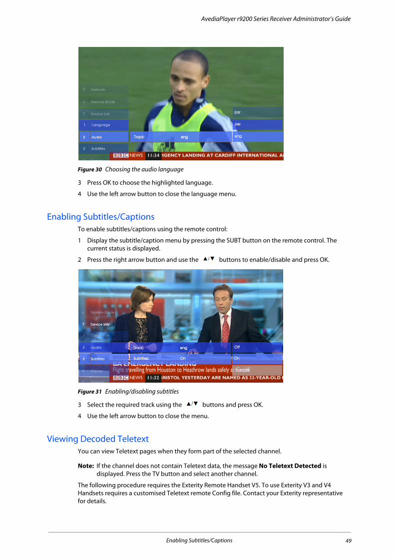
AvediaPlayer r9200 Series Receiver Administrator’s Guide
Figure 30 Choosing the audio language
3 Press OK to choose the highlighted language.
4 Use the left arrow button to close the language menu.
Enabling Subtitles/CaptionsTo enable subtitles/captions using the remote control:
1 Display the subtitle/caption menu by pressing the SUBT button on the remote control. The current status is displayed.
2 Press the right arrow button and use the buttons to enable/disable and press OK.
Figure 31 Enabling/disabling subtitles
3 Select the required track using the buttons and press OK.
4 Use the left arrow button to close the menu.
Viewing Decoded TeletextYou can view Teletext pages when they form part of the selected channel.
Note: If the channel does not contain Teletext data, the message No Teletext Detected is displayed. Press the TV button and select another channel.
The following procedure requires the Exterity Remote Handset V5. To use Exterity V3 and V4 Handsets requires a customised Teletext remote Config file. Contact your Exterity representative for details.
Enabling Subtitles/Captions 49

AvediaPlayer r9200 Series Receiver Administrator’s Guide
To use decoded Teletext:
1 Select a channel known to carry Teletext data.
2 Press the TEXT button. The Teletext banner is displayed while the Teletext pages are loaded, and the Teletext index page is displayed:
Figure 32 Example Teletext page
3 Enter the required page using the number keys or the Green/Red/Blue buttons if fast links are displayed. Page up or down using the Channel +/- buttons.
4 Use the OK button to zoom to the upper and lower halves of the pages if needed.
5 Use Up/Down buttons to step up or down page numbers.
6 Use Left/Right arrows to manually step through subpages. Pressing the Stop button pauses/resumes automatic sub page changing. You can continue to step through sub pages even when no more are available. The last viewed page remains displayed and you can step back through the previously viewed pages using the Left arrow button.
7 Press TV to exit Teletext and return to the channel program content.
Using the Web BrowserIf configured, you can use the browser to view content on your television or display. You can control how pages are displayed using the web management interface, as described in Configuring Web Services. For example, you can define a home page to display when the browser opens, and you can specify whether or not pages display with a menu bar.
• To go to the home page, press the HOME button.
• To return to the home page, press the HOME button.
• To navigate between links (if available), use the up/down/left/right buttons.
• To select a link, press the OK button.
Using the Web Browser 50
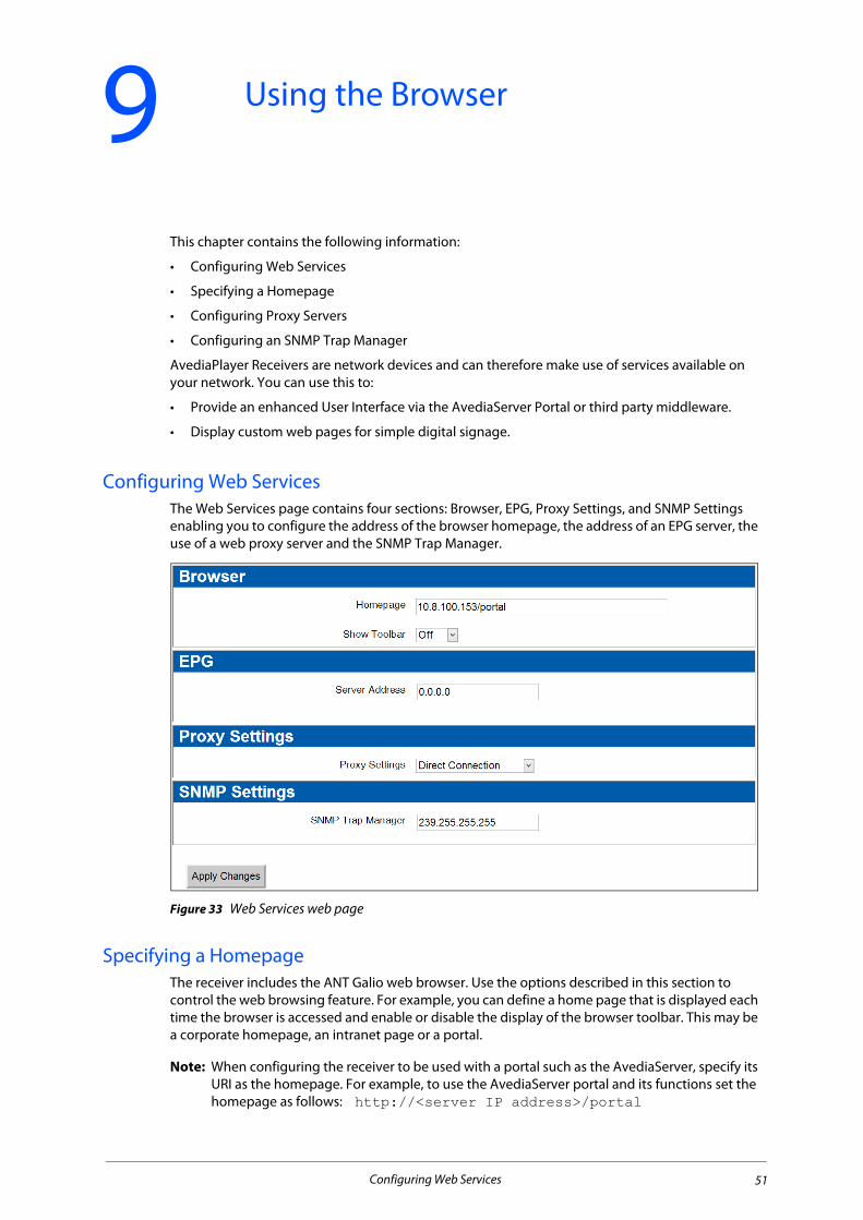
9 Using the Browser
This chapter contains the following information:
• Configuring Web Services
• Specifying a Homepage
• Configuring Proxy Servers
• Configuring an SNMP Trap Manager
AvediaPlayer Receivers are network devices and can therefore make use of services available on your network. You can use this to:
• Provide an enhanced User Interface via the AvediaServer Portal or third party middleware.
• Display custom web pages for simple digital signage.
Configuring Web ServicesThe Web Services page contains four sections: Browser, EPG, Proxy Settings, and SNMP Settings enabling you to configure the address of the browser homepage, the address of an EPG server, the use of a web proxy server and the SNMP Trap Manager.
Figure 33 Web Services web page
Specifying a HomepageThe receiver includes the ANT Galio web browser. Use the options described in this section to control the web browsing feature. For example, you can define a home page that is displayed each time the browser is accessed and enable or disable the display of the browser toolbar. This may be a corporate homepage, an intranet page or a portal.
Note: When configuring the receiver to be used with a portal such as the AvediaServer, specify its URI as the homepage. For example, to use the AvediaServer portal and its functions set the homepage as follows: http://<server IP address>/portal
Configuring Web Services 51

AvediaPlayer r9200 Series Receiver Administrator’s Guide
To view the browser on a television or display, press the HOME button on the remote control. Alternatively, you can use the web interface or the AvediaServer Director application to put the receiver into Web Browser mode.
Figure 34 AvediaServer portal interface
To set a browser home page:
1 Click Web Services to display the page as shown in Figure 33.
2 Enter the URL of the web page you want to configure as the homepage location into the Homepage field. For example:
• http://<ipaddress>/portal – a local AvediaServer Portal
• http://www.myfavouritepage.com – an internal/external webpage
Figure 35 Setting the browser home page
3 Select On or Off as required from the Show Toolbar drop-down list. The default value is Off. When On, the ANT Galio toolbar is displayed at the top of the screen as shown in Figure 36.
4 Click Apply Changes.
Figure 36 Toolbar enabled
Specifying an EPGThis section describes how to configure the receiver for interoperation with the Exterity AvediaServer Electronic Program Guide (EPG) application.
Note: This section applies only if your version of AvediaServer is earlier than version 4.0.0. From version 4.0.0 onwards, the EPG is configured using the AvediaServer Portal.
The EPG application provides a web page which the receiver can access. This is displayed on the connected television or display and allows you to browse and select from the available programs. To use the AvediaServer EPG generator set the EPG as follows:
http://<server IP address>/epg
To view the EPG on a television or display, press the GUIDE button on the remote control.
Specifying an EPG 52
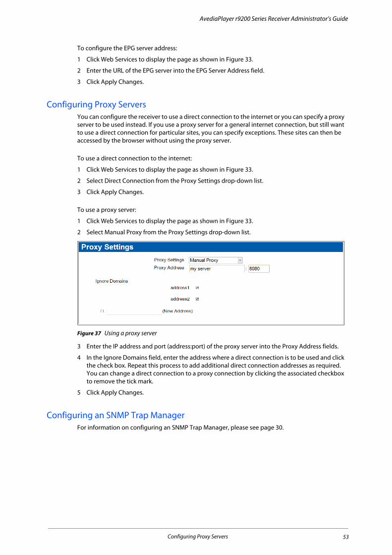
AvediaPlayer r9200 Series Receiver Administrator’s Guide
To configure the EPG server address:
1 Click Web Services to display the page as shown in Figure 33.
2 Enter the URL of the EPG server into the EPG Server Address field.
3 Click Apply Changes.
Configuring Proxy ServersYou can configure the receiver to use a direct connection to the internet or you can specify a proxy server to be used instead. If you use a proxy server for a general internet connection, but still want to use a direct connection for particular sites, you can specify exceptions. These sites can then be accessed by the browser without using the proxy server.
To use a direct connection to the internet:
1 Click Web Services to display the page as shown in Figure 33.
2 Select Direct Connection from the Proxy Settings drop-down list.
3 Click Apply Changes.
To use a proxy server:
1 Click Web Services to display the page as shown in Figure 33.
2 Select Manual Proxy from the Proxy Settings drop-down list.
Figure 37 Using a proxy server
3 Enter the IP address and port (address:port) of the proxy server into the Proxy Address fields.
4 In the Ignore Domains field, enter the address where a direct connection is to be used and click the check box. Repeat this process to add additional direct connection addresses as required. You can change a direct connection to a proxy connection by clicking the associated checkbox to remove the tick mark.
5 Click Apply Changes.
Configuring an SNMP Trap ManagerFor information on configuring an SNMP Trap Manager, please see page 30.
Configuring Proxy Servers 53

10 Using Secure Mode
This chapter details Secure Mode and contains the following information:
• Overview
• Entering/Exiting Secure Mode
• Passwords
• Exporting/Importing Configuration
• Resetting the Receiver to Factory Defaults
• Enabling/Disabling Parts of Secure Mode
OverviewAvediaPlayer Receivers have a Secure Mode feature which allows them to comply with content protection requirements from some broadcasters, such as Canal+ in France.
Caution: Please be aware that when receivers are in Secure Mode, they can no longer be accessed using the AvediaServer Director application (or any third-party SNMP management tool), and any configuration must be carried out individually on each unit.
AvediaPlayer Receivers can be run in either Normal or Secure Mode. The differences are as follows:
* Because SNMP is disabled in Secure Mode, please note that the AvediaServer Director application cannot be used to manage the receiver.
† These functions can be re-enabled once in Secure Mode, if required. Please see “Enabling/Disabling Parts of Secure Mode” on page 58.
Table 3
Function Normal Mode Secure Mode
SNMP* On Off
USB storage† On Off
Web Interface† On Off
Reset button† Factory reset Disabled
Power cycle Enabled Enabled
TV control/serial mode Enabled Enabled
Telnet Enabled for admin/ctrl login Disabled
SSH Enabled for admin/ctrl login Enabled for admin/ctrl login
Passwords Weak passwords allowed Strict passwords only
Overview 54

AvediaPlayer r9200 Series Receiver Administrator’s Guide
Entering/Exiting Secure ModeTo enter or exit Secure Mode, use the Admin Interface, or the Terminal Command Interface.
Using the Admin Interface To enter Secure Mode:
1 Log into the Admin Interface.
2 Choose option 6 to open a shell.
3 At the shell prompt, enter:
configwrite securitySetting strict
To exit Secure Mode:
1 Log into the Admin Interface
2 Choose option 6 to open a shell.
3 At the shell prompt, enter:
configwrite securitySetting normal
4 Reboot the AvediaPlayer Receiver.
Using the Terminal Command Interface (TCI)For details on using the Terminal Command Interface, please refer to the Exterity Receiver Developer’s Guide.
To enter Secure Mode, enter the following on the TCI:
^set:securitySetting:strict!
To exit Secure Mode, enter the following on the TCI:
^set:securitySetting:normal!
When returning to Normal Mode, reboot the AvediaPlayer Receiver.
Passwords
Normal ModeIn Normal Mode, the default username and password are as follows:
admin/ctrl
labrador
Secure ModeIn Secure Mode, the admin and ctrl passwords remain the same as in Normal Mode until changed. The default values are:
admin/ctrl
labrador
Caution: To comply with the content protection requirements of Canal+, the system administrator must change the Secure Mode password immediately, and then at least once a month thereafter.
Entering/Exiting Secure Mode 55
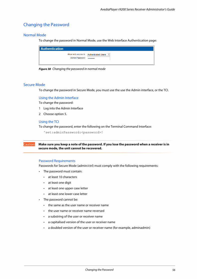
AvediaPlayer r9200 Series Receiver Administrator’s Guide
Changing the Password
Normal ModeTo change the password in Normal Mode, use the Web Interface Authentication page:
Figure 38 Changing the password in normal mode
Secure ModeTo change the password in Secure Mode, you must use the use the Admin interface, or the TCI.
Using the Admin Interface To change the password:
1 Log into the Admin Interface
2 Choose option 5.
Using the TCITo change the password, enter the following on the Terminal Command Interface:
^set:adminPassword:<password>!
Caution: Make sure you keep a note of the password. If you lose the password when a receiver is in secure mode, the unit cannot be recovered.
Password RequirementsPasswords for Secure Mode (admin/ctrl) must comply with the following requirements:
• The password must contain:
• at least 10 characters
• at least one digit
• at least one upper case letter
• at least one lower case letter
• The password cannot be:
• the same as the user name or receiver name
• the user name or receiver name reversed
• a substring of the user or receiver name
• a capitalised version of the user or receiver name
• a doubled version of the user or receiver name (for example, adminadmin)
Changing the Password 56

AvediaPlayer r9200 Series Receiver Administrator’s Guide
Exporting/Importing ConfigurationYou can copy the configuration from one receiver to others by exporting the configuration from the initial receiver, then importing it onto other devices.
Exporting ConfigurationTo export configuration when in Secure Mode, you use the Admin Interface or the TCI.
Using the Admin Interface 1 Log in as admin.
2 Choose option 6 to open a shell.
3 Enter configwrite exportConfig <filename>.
Using the TCI1 Log in as ctrl.
2 Enter the following on the TCI:
^set:exportConfig:<filename>!
Importing Configuration
Using the Admin Interface To import configuration to a single device:
1 Log in as admin.
2 Choose option 6 to open a shell.
3 Enter configwrite importConfig <filename>.
Using the TCITo import configuration to a single device:
1 Log in as ctrl.
2 Enter the following on the TCI:
^set:importConfig:<filename>!
Using AvediaServer DirectorYou can use the Director application to import configuration to one or multiple devices. Please see “Exporting and Importing AvediaPlayer Receiver Configuration” on page 63 for details.
Caution: Please be aware that once receivers are in Secure Mode, they can no longer be accessed using the Director application, and all configuration must be carried out individually on each unit.
Resetting the Receiver to Factory DefaultsIn Normal Mode, you can use the Web Interface, Admin Interface, TCI or the reset button to reset the receiver to factory defaults. Please see “Returning to Factory Default Settings” on page 63 for details.
To reset the receiver when in Secure Mode, you can only use the Admin Interface or TCI commands (as in Normal Mode).
Caution: Once the receiver has been reset to factory defaults, it is no longer in Secure Mode.
Exporting/Importing Configuration 57
AvediaPlayer r9200 Series Receiver Administrator’s Guide
Enabling/Disabling Parts of Secure ModeCertain functionality is unavailable by default in Secure Mode, as shown in Table 3. This section details this functionality, and explains how to re-enable it once in Secure Mode using the Admin Interface or the Terminal Control Interface.
Caution: Please note that if you re-enable any of this functionality, the receiver no longer complies with the content protection requirements stipulated by Canal+.
Enabling/Disabling the Factory Defaults Reset ButtonTo enable or disable the factory defaults button on the back of the device when in Secure Mode enter the following:
Using the Admin Interface To enable: configwrite factoryResetButton on
To disable: configwrite factoryResetButton off
Using the TCITo enable: ^set:factoryResetButton:<on>!
To disable: ^set:factoryResetButton:<off>!
Note: Power cycling and changing between TV control and serial mode is available in Secure Mode.
Enabling/Disabling USB Storage AccessIn Normal Mode, USB storage devices are automatically mounted when connected. In Secure Mode, you must enable mounting to use USB storage devices.
To enable or disable storage device mounting in Secure Mode, enter the following:
Using the Admin Interface To enable: configwrite USBStorageAccess on
To disable: configwrite USBStorageAccess off
Using the TCITo enable: ^set:USBStorageAccess:<on>!
To disable: ^set:USBStorageAccess:<off>!
Enabling/Disabling the Web Admin InterfaceBy default, the Web Admin Interface is not available when the device is in Secure Mode. To enable or disable the Web Admin Interface, enter the following:
Using the Admin Interface To enable: configwrite webAccess on
To disable: configwrite webAccess off
Using the TCITo enable: ^set:webAccess:<on>!
To disable: ^set:webAccess:<off>!
Enabling/Disabling Parts of Secure Mode 58
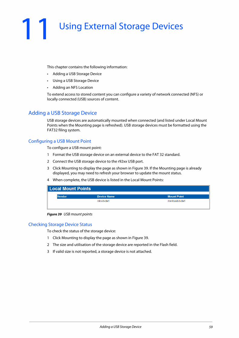
11 Using External Storage Devices
This chapter contains the following information:
• Adding a USB Storage Device
• Using a USB Storage Device
• Adding an NFS Location
To extend access to stored content you can configure a variety of network connected (NFS) or locally connected (USB) sources of content.
Adding a USB Storage Device USB storage devices are automatically mounted when connected (and listed under Local Mount Points when the Mounting page is refreshed). USB storage devices must be formatted using the FAT32 filing system.
Configuring a USB Mount PointTo configure a USB mount point:
1 Format the USB storage device on an external device to the FAT 32 standard.
2 Connect the USB storage device to the r92xx USB port.
3 Click Mounting to display the page as shown in Figure 39. If the Mounting page is already displayed, you may need to refresh your browser to update the mount status.
4 When complete, the USB device is listed in the Local Mount Points:
Figure 39 USB mount points
Checking Storage Device StatusTo check the status of the storage device:
1 Click Mounting to display the page as shown in Figure 39.
2 The size and utilisation of the storage device are reported in the Flash field.
3 If valid size is not reported, a storage device is not attached.
Adding a USB Storage Device 59

AvediaPlayer r9200 Series Receiver Administrator’s Guide
Figure 40 USB storage device content
Using a USB Storage Device There are three ways in which you can use a storage device to extend access to stored content.
• Pre-load the storage device with required content before connecting to the receiver.
• Mount the storage device on the receiver, then download a playlist and its media files to the storage device from an external server.
• Use an FTP client to ‘push’ content onto the device.
Pre-loading the Storage DeviceTo use content from a pre-loaded storage device:
1 Copy the required content to the storage device.
2 Attach the storage device to the receiver’s USB port.
3 Click Display.
4 In the URLs section, enter the path to the playlist in the format detailed in Appendix A, "Playlist Format".
5 In the Display section, select Playlist from the Current Mode drop-down list.
6 Click Apply Changes.
Downloading a Playlist from an External Server
Caution: All contents of the storage device are removed when you click Download Playlist. We recommend that you back up any content you want to keep before downloading a playlist.
To download a playlist and content to the USB storage device:
1 Attach the storage device to the receiver’s USB port.
2 Click Mounting to display the page as shown in Figure 39.
3 In the Download Playlist section, enter the path to the playlist in the format detailed in Appendix A, "Playlist Format".
Note: The final line of the playlist file must always contain a blank line (carriage return).
4 Click the Save Playlist button.
The playlist and its content are downloaded to the USB storage device and can be used for failover or as current content. All current content on the storage device is overwritten.
Refer to Chapter 12, "Channel Redundancy and Failover" and “Playing a Playlist” on page 37 for more information.
Using a USB Storage Device 60

AvediaPlayer r9200 Series Receiver Administrator’s Guide
Downloading a Playlist using FTPTo download to the USB storage device using FTP:
1 Ensure a local mount point has been created and the storage device is connected.
2 Click Mounting and make a note of the Mount Point listed in the Local USB Mount Points table. (/mnt/usb/sda1 in Figure 39).
3 Open your FTP client and connect to the AvediaPlayer Receiver, entering its IP address and control credentials (ctrl/labrador).
4 Confirm the connection has been made and the mount point path is displayed.
5 Navigate the local directories to locate and transfer the file(s) required.
Figure 41 Downloading using FTP
The file can now be played directly or used as part of the failover mechanism.
Note: The anonymous ftp login to the AvediaPlayer provides read only access to the mounted storage device.
Deleting a Playlist from a Storage DeviceTo delete all content from the storage device:
1 Click Mounting to display the mounted storage devices.
2 In the Download Playlist section, click the Clear Playlist button.
Caution: All contents of the storage device are removed when you click Clear Playlist. We recommend that you back up any content you want to keep before deleting a playlist.
Adding an NFS LocationAn NFS (Network File System) location allows you to access content stored on another network device. You must specify the directory on the network device where the content is stored, and a local directory on the receiver which acts as a mirror to the remote directory.
To configure a remote storage NFS mount point:
1 Click Mounting to display the Mounting page.
2 Enter the IP address of the remote host, the remote directory path, and the local directory into the respective Add New NFS Mount Point fields.
Adding an NFS Location 61

AvediaPlayer r9200 Series Receiver Administrator’s Guide
Note: The default local directory is /mnt. When specifying the local directory, please note that the receiver allows only one level of subdirectory, for example, /mnt/playlists. If you create more than one level, for example, /mnt/playlists/new, the receiver merges this to /mnt/playlistsnew.
3 Click Mount to start the mounting process. When successfully mounted, the new mount point is listed in the Existing NFS Mount Points list:
Figure 42 Adding a new NFS mount point
A green indicator is displayed when the mounting process has successfully completed.
4 To remove the connection, click the UnMount button.
Adding an NFS Location 62
12 Channel Redundancy and Failover
The AvediaPlayer Receiver has two mechanisms to ensure content is always displayed if the channel being played fails.
• Channel Redundancy – this mechanism checks for availability of another channel of the same name and group membership as the channel which has failed, and is available in all modes.
• Failover – this mechanism involves playing another channel, playing back video file(s) from a mounted storage device, or launching a page to display in the browser.
Note: Failover is only available in AV mode.
Channel RedundancyChannel redundancy requires an available duplicate channel with the same name and group membership as the original channel. When multiple identical channels exist, each is tried in turn until one is successfully played. If all attempts to play the redundant channel(s) fail, the receiver initiates the failover mechanism (if it is enabled). Refer to the Exterity Gateway, Encoder and AvediaServer documentation for more information about stream naming and group membership. Channel Redundancy is independent of failover configuration.
Note: Redundant (duplicate) channel numbers/names are not displayed on the connected TV/Display.
FailoverFailover allows you to configure the receiver to respond to the loss of the currently playing channel. When the failed stream returns (on the original address) the receiver automatically switches back to it (if no other channel has been manually selected). No operator intervention is required.
Configuring FailoverYou can configure the following responses:
• Play media using either another network streamed channel, or a media file (in transport stream format) located on a local or remote storage device (refer to Chapter 11, "Using External Storage Devices").
• Play a playlist saved to a local storage device, or from a remote location (Chapter 11, "Using External Storage Devices").
• Display a web page using the receiver’s browser. (Include a stream playing with a browser video object if required.)
Note: If one or more redundant channels have been configured, the receiver will attempt to play these first, only initiating the failover mechanism if the redundant channel(s) also fail.
To fail over to media:
1 Click Maintenance to display the page as shown in Figure 44.
2 In the Fail Over section, select Enabled from the State drop-down list.
3 Select Media from the Backup Channel drop-down list.
Channel Redundancy 63

AvediaPlayer r9200 Series Receiver Administrator’s Guide
Figure 43 Media failover setup
4 Enter the URL of the media in the form:
• Multicast stream (UDP or RTP), for example: udp://239.192.0.72:5000
• Source Specific Multicast stream (UDP or RTP), for example: udp://[email protected]:5000
• On Demand playback (RTSP), for example: rtsp://10.8.64.72:8554/football.mpg
• File from a mounted storage device, for example: file:///mnt/usb/sda1/mediafile/topcat.ts
5 Click Apply Changes.
To fail over to a playlist:
1 Click Maintenance to display the page as shown in Figure 44.
2 In the Fail Over section, select Enabled from the State drop-down list.
3 Select Playlist from the Backup Channel drop-down list.
4 Enter the URL of the playlist in the form:
• Playlist from a web server, for example: http://10.8.64.72:8554/playlist
• Playlist from a mounted storage device, for example: file:///mnt/usb/sda1/mediafile/playlist
5 Click Apply Changes.
To fail over to a web page:
1 Click Maintenance to display the page as shown in Figure 44.
2 In the Fail Over section, select Enabled from the State drop-down list.
3 Select Browser from the Backup Channel drop-down list.
4 Enter the URL of the webpage in the form:
http://www.myfailoverpage.com
5 Click Apply Changes.
Troubleshooting FailoverIf you have configured failover, and the selected replacement is not available, an error message is displayed to indicate this. Please note that this does not apply in the following circumstances:
• You have selected to fail over to a web page, and this page cannot be found. No error message is displayed.
• You have selected to fail over to a playlist, and there is an error within the playlist. Again, no error message is displayed.
Failover 64

13 Extended AvediaPlayer Features
Additional AvediaPlayer Receiver capabilities are available beyond those available from the web admin interface. These are as follows:
• Adding Static Channels
• Customising the Client User Interface
• Adding More Client Interface Languages and Fonts
• Receiver Development Kit (RDK)
Adding Static ChannelsThe AvediaPlayer r92xx series receivers also support the use of Static Channels. These can be channels where you want to:
• Include some files held on local/remote storage devices and include them in the channel listing.
• Include content from a source that does not use SAP to announce the presence of the channel.
• Add a channel but hide its listing from the Program Guide.
For more information about the tools and processes required to configure Static Channels refer to the Exterity Knowledge Base article KB00029.
Customising the Client User InterfaceThe graphical, textual and animation features of the Client User Interface are defined by a Cascading Style Sheet (CSS). Elements of the Client User Interface defined in the CSS can be customised as required and re-applied. Exterity Knowledge Base article KB000306 describes the steps in detail.
You can customise elements such as:
• Colour of highlighted function
• Colour of text
• Level of transparency
• Speed of transition between selections
Figure 44 Part of Client UI CSS
Adding Static Channels 65
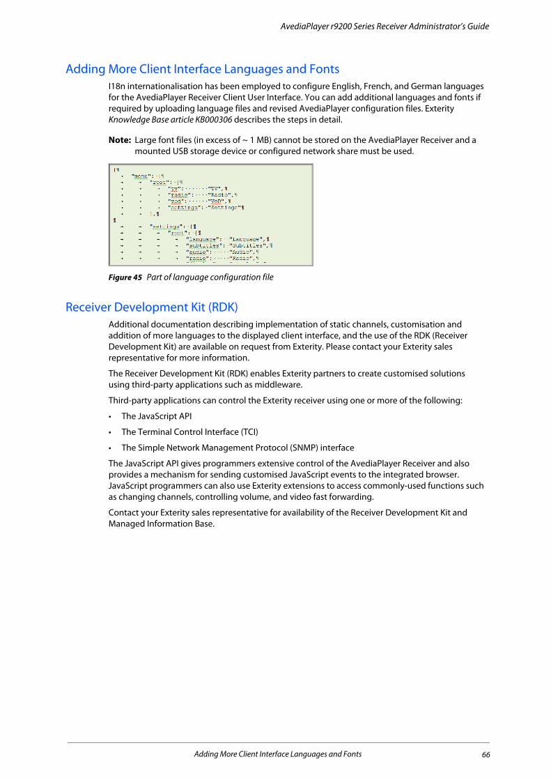
AvediaPlayer r9200 Series Receiver Administrator’s Guide
Adding More Client Interface Languages and FontsI18n internationalisation has been employed to configure English, French, and German languages for the AvediaPlayer Receiver Client User Interface. You can add additional languages and fonts if required by uploading language files and revised AvediaPlayer configuration files. Exterity Knowledge Base article KB000306 describes the steps in detail.
Note: Large font files (in excess of ~ 1 MB) cannot be stored on the AvediaPlayer Receiver and a mounted USB storage device or configured network share must be used.
Figure 45 Part of language configuration file
Receiver Development Kit (RDK) Additional documentation describing implementation of static channels, customisation and addition of more languages to the displayed client interface, and the use of the RDK (Receiver Development Kit) are available on request from Exterity. Please contact your Exterity sales representative for more information.
The Receiver Development Kit (RDK) enables Exterity partners to create customised solutions using third-party applications such as middleware.
Third-party applications can control the Exterity receiver using one or more of the following:
• The JavaScript API
• The Terminal Control Interface (TCI)
• The Simple Network Management Protocol (SNMP) interface
The JavaScript API gives programmers extensive control of the AvediaPlayer Receiver and also provides a mechanism for sending customised JavaScript events to the integrated browser. JavaScript programmers can also use Exterity extensions to access commonly-used functions such as changing channels, controlling volume, and video fast forwarding.
Contact your Exterity sales representative for availability of the Receiver Development Kit and Managed Information Base.
Adding More Client Interface Languages and Fonts 66

14 Maintenance
This chapter describes various maintenance tasks. It covers:
• Specifying the TFTP Server Address
• Specifying the SNMP Trap Manager IP Address
• Specifying the Time Server Address
• Restarting the Receiver
• Upgrading Firmware
• Restoring Factory Defaults
• Exporting/Importing Configuration Settings
• Logging
Maintenance tasks are managed from the Maintenance page.
Specifying the TFTP Server AddressThe receiver uses TFTP to download new firmware releases, remote control configuration files and splash screens. For this to operate correctly, it must be configured to communicate with the TFTP server.
To specify the TFTP server IP address:
1 Click Maintenance.
2 Enter the IP address of the TFTP server in the TFTP Server field.
3 Click Apply Changes.
Specifying the SNMP Trap Manager IP Address SNMP traps are mainly used as device discovery messages; they enable Exterity’s management applications to discover devices on the network. These traps are always broadcast on the local subnet. They are also transmitted to an additional configurable destination. By default, this is the multicast address 239.255.255.255, but this can be reconfigured to any broadcast, multicast or unicast destination as required.
To set the SNMP trap manager address:
1 Click Web Services.
2 Enter the required IP address in the SNMP Trap Manager field.
3 Click Apply Changes.
Specifying the Time Server AddressUsing a Time Server with the Time Zone configuration ensures all devices in your IPTV system are synchronised to the current local time in use. The receiver uses NTP (Network Time Protocol) to maintain accurate time on the device, using the time server specified. This is useful when examining the device log file as each log message has an accurate universal time code (UTC) timestamp.
Specifying the TFTP Server Address 67

AvediaPlayer r9200 Series Receiver Administrator’s Guide
Note: When DHCP is used and the DHCP server supplies an NTP server address, any NTP servers configured using the Web Management Interface are ignored. If the DHCP server does not supply an NTP server address, the address must be configured.
To specify a time server:
1 Click Maintenance.
2 Enter the IP address or the host name of the time server in the Time Server field. If already configured, the IP address is displayed.
3 Click Apply Changes.
Restarting the ReceiverYou can restart the receiver to return it to a known state. All current settings are maintained during a reboot.
To restart the receiver:
1 Click Maintenance.
2 Select Reboot from the Operation drop-down list.
3 Click Apply Changes.
During the reboot process the connected television or display is blanked as the AvediaPlayer restarts and follows the sequence described in the Power On section of the AvediaPlayer Getting Started Guide.
Note: You can also restart the receiver by briefly pressing and releasing the RESET button on the rear panel.
Upgrading FirmwareBy upgrading firmware regularly, you can ensure that you are always using the most recent version. As the new firmware is uploaded using TFTP, you must first ensure that the receiver is using the correct TFTP server address.
Caution: Do not switch the receiver off while the upgrade process is underway. The process takes several minutes.
Note: If you have upgraded to version 2 from any previous version, you must first reset the device to factory defaults, or manually delete the /usr/local/etc/httpd.conf file before logging into the web interface.
To upgrade the receiver to a new version of firmware:
1 Click Maintenance.
2 Ensure that you have specified the IP address of your TFTP server in the Settings section of the page and that it is running and configured correctly.
3 Ensure that the following firmware file is hosted correctly in the root directory of the TFTP server:
avediaplayer.bin.enc
4 Ensure that the Boot Imagefield shows the file indicated above (or matches the name of the firmware file if this is different).
5 Click the Operation drop-down list to select Upgrade Firmware.
6 Click Apply Changes.
Restarting the Receiver 68
AvediaPlayer r9200 Series Receiver Administrator’s Guide
7 The firmware is downloaded from the TFTP server and copied to flash, and the receiver restarted. This process will take several minutes.
You can specify the name of the file you want to use when uploading and installing receiver firmware. This allows you to manage firmware for multiple receiver models and versions by including relevant information in the name of the firmware files held on your server. Specify the required file when performing the upgrade.
Restoring Factory DefaultsYou can return the receiver to its factory default configuration using the web management interface as described in the following procedure, or using the rear panel RESET function.
Note: When resetting to factory default settings, all previously saved settings are lost. IP addressing is also returned to DHCP. You can however restore previous settings if you have saved your configuration, as described later in this section.
To restore the factory default settings:
1 Click Maintenance.
2 Click the Operation drop-down list to select Return to Factory Defaults.
3 Click Apply Changes.
During the reboot process the connected television or display is blanked as the AvediaPlayer restarts and follows the sequence described in the Power On section of the AvediaPlayer Getting Started Guide.
Note: You can also return the AvediaPlayer Receiver to factory defaults by pressing and holding RESET, releasing only when the TV and ADM LEDs both flash together.
Exporting/Importing Configuration SettingsOnce you have set up the receiver, you can save its configuration settings in a single file. You can use the saved configuration file to restore the settings if required, or replicate identical settings on additional devices. The configuration files are exported and imported using the TFTP process.
Note: Please note that you cannot use configuration settings from version 2.x receivers on version 3.x receivers, and vice versa.
Note: Device naming and IP addressing information is not exported/imported. This means that a configuration file can be imported to multiple units.
To export configuration settings:
1 Ensure that the TFTP server is running and is correctly configured (see above).
2 Click Maintenance.
3 Select Export Configuration from the Operation drop-down list.
4 Enter a name for your configuration archive in the Export filename field.
Restoring Factory Defaults 69

AvediaPlayer r9200 Series Receiver Administrator’s Guide
Figure 46 Exporting configuration using TFTP
5 Click Apply Changes.
To export configuration settings using a browser file download function:
1 Click Maintenance.
2 Click the Operation drop-down list to select Export Configuration.
Note: The file name is <export.tar.gz> and cannot be changed prior to downloading.
3 Click the (Download) hyperlink.
4 If required, select the destination location for the configuration file.
To import configuration settings:
1 Ensure that the TFTP server is running and that the configuration file is hosted in the root directory of the TFTP server.
2 Click Maintenance.
3 Enter the name of the configuration file in the Import Filename field.
4 Click the Operation drop-down list to select Import Configuration.
5 Enter the name of the required configuration archive in the Import File Name field.
6 Click Apply Changes.
7 The configuration file is downloaded from the TFTP server and the receiver reboots.
LoggingThe receiver saves historical information about internal events within the device to its log file. This can be useful in troubleshooting problems with the device. All log file information is automatically saved locally and can be viewed in the Web Interface. It is also possible to send these log messages to a remote syslog server.
Use of a Time Server with the Time Zone configuration ensures all devices in your IPTV system are synchronised. The receiver uses NTP to maintain an accurate time on the device, useful when examining log files as each log message has an accurate timestamp (UTC time zone).
Logging is configured in the web interface Logging page as shown in Figure 47.
Logging 70

AvediaPlayer r9200 Series Receiver Administrator’s Guide
Figure 47 Logging Page - local and remote selected
Local LoggingYou can view the log file in the Web Interface or download it to your computer.
To view the log file:
1 Click Logging.
2 Click View Log to display the log in a browser window.
3 Click Hide Log button to close the log display.
To download the log file:
1 Click Logging.
2 Click the Download log button to download the log file to the configured download folder on your local computer.
Note: Exterity recommends that you use Wordpad to view the downloaded log file.
Remote LoggingTo send device log information to a remote server, you need to install a syslog server application on the remote server. Then set up the remote logging function on the receiver as described below.
To configure remote logging:
1 Click Logging.
2 Select Local and Remote from the Logging drop-down list.
3 In the Syslog server field, enter the IP address or host name of the syslog server where the log files are to be stored.
4 In the Syslog port field, enter the port number on the syslog server. The default value is 514.
5 Click the Logging level drop-down list and select an option ranging from 0-Emergency to 7-Debug, where 0 represents the least debug information and 7 represents the most.
6 Click Apply.
Logging 71

15 Troubleshooting
Problem Possible Cause Solution
Device does not appear in AvediaServer Director
Network connection faulty or cannot obtain IP address (indicated by LED flash 4 times per second and on-screen message)
Check Ethernet connections or replace cable.
Check that DHCP server is running on network.
AvediaServer Device Listener turned off Open AvediaServer Status > Service page and turn on Device Listener.
Device may be in Secure Mode Switch the device back into Normal Mode. See Chapter 10, "Using Secure Mode".
AvediaServer Director cannot communicate with device
Network connection faulty See above.
Device has an IP address on a different subnet to the management station
Use a management station configured with an appropriate IP address to manage the device.
Device is upgrading Wait for upgrade to complete
No picture on television Incorrect AV cabling Check cabling.
The wrong AV input is selected on the TV. Find the appropriate AV input.
Channel(s) missing from channels list
Network connection faulty See above
The head-end device(s) is/are not properly connected to the network.
Ensure Director can communicate with the head-end device(s) and investigate if not.
The head-end device(s) is/are on a different subnet from the receiver.
Configure multicast routing on network.
Groups are configured, but the channel and receiver are not in the same group.
Correct the Groups configuration on the Groups tab.
Cannot connect to channel (“This channel is not available”)
Either receiver or head-end device are not on the network.
Ensure the AvediaServer Director can communicate with the devices and investigate if not.
Blank screen when changing channel
Network port overloaded. Ensure that network is multicast-enabled.
Video freezes or continually stutters
Network port overloaded. Ensure that network is multicast-enabled.
Cannot connect to URL You are using invalid proxy settings. Check your proxy settings on Browser tab.
After upgrade, the device is still running the old version of firmware
The correct firmware file is not on the TFTP server
Put the correct file on the TFTP server.
The TFTP server is not running Start the TFTP server
The TFTP server is not configured to send files.
Fix the security settings on the TFTP server.
Cannot log in to web interface Reset to factory defaults required after upgrade to version 3.2 firmware from any previous version.
Reset the device to factory defaults after upgrading, or
Manually delete the /usr/local/etc/httpd.conf file before logging into the web interface
72
A Playlist Format
Sample playlist files are shown below.
Note: There can be more than one playlist string in a playlist text file, but the final line of the file must always contain a blank line (carriage return).
Example 1 – Remote content from a web server:
media:http://10.8.64.72/video/news1.mpg
media:http://10.8.64.72/video/sport1.mpg
media:http://10.8.64.72/video/news2.mpg
media:http://10.8.64.72/video/cartoon.mpg
media:http://10.8.64.72/video/film.mpg
Example 2 – Local content from a USB storage device:
media:file:///mnt/usb/sda1/news1.mpg
media:file:///mnt/usb/sda1/sport.mpg
media:file:///mnt/usb/sda1/news2.mpg
media:file:///mnt/usb/sda1/cartoon.mpg
media:file:///mnt/usb/sda1/film.mpg
Note: The video files must be in MPEG-2 Transport Stream format.
Note: To ensure smooth playback of a playlist, you should ensure that each item in the playlist requires the same codec and that the frame rate is the same whenever possible. Re-configuration during playback caused by dissimilar content can result in periods of no output on the client display.
73
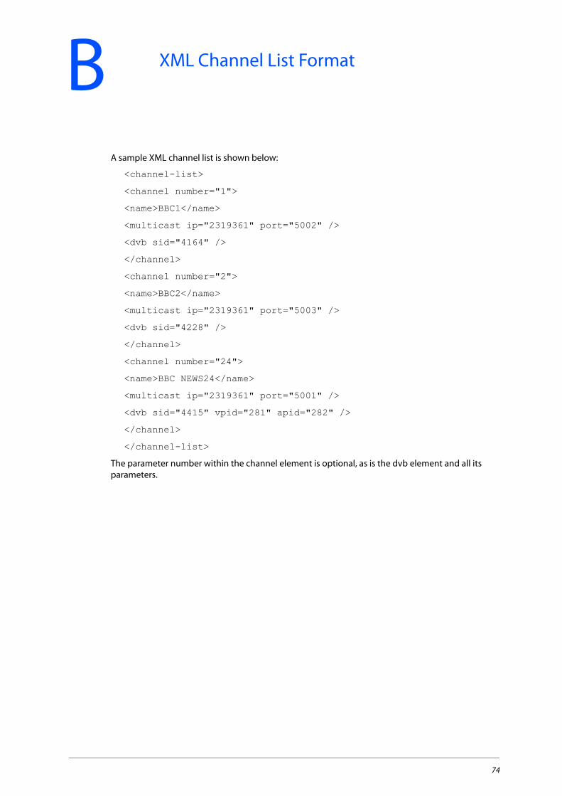
B XML Channel List Format
A sample XML channel list is shown below:
<channel-list>
<channel number="1">
<name>BBC1</name>
<multicast ip="2319361" port="5002" />
<dvb sid="4164" />
</channel>
<channel number="2">
<name>BBC2</name>
<multicast ip="2319361" port="5003" />
<dvb sid="4228" />
</channel>
<channel number="24">
<name>BBC NEWS24</name>
<multicast ip="2319361" port="5001" />
<dvb sid="4415" vpid="281" apid="282" />
</channel>
</channel-list>
The parameter number within the channel element is optional, as is the dvb element and all its parameters.
74
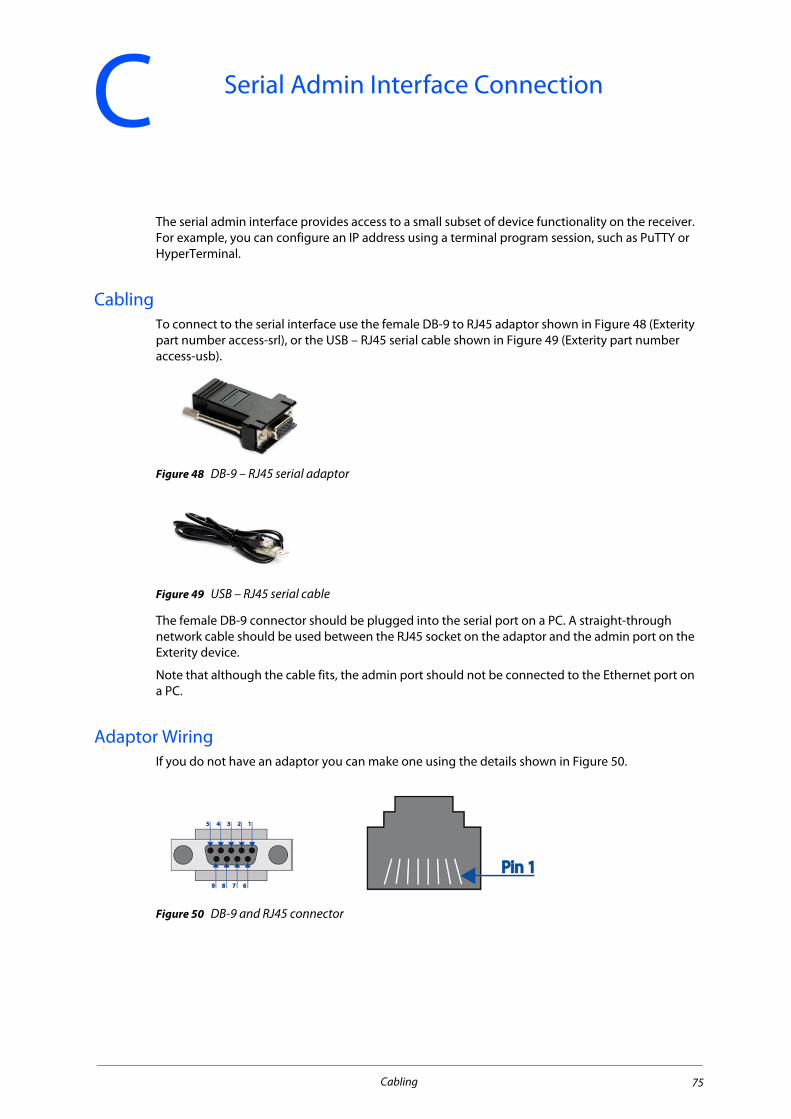
C Serial Admin Interface Connection
The serial admin interface provides access to a small subset of device functionality on the receiver. For example, you can configure an IP address using a terminal program session, such as PuTTY or HyperTerminal.
CablingTo connect to the serial interface use the female DB-9 to RJ45 adaptor shown in Figure 48 (Exterity part number access-srl), or the USB – RJ45 serial cable shown in Figure 49 (Exterity part number access-usb).
Figure 48 DB-9 – RJ45 serial adaptor
Figure 49 USB – RJ45 serial cable
The female DB-9 connector should be plugged into the serial port on a PC. A straight-through network cable should be used between the RJ45 socket on the adaptor and the admin port on the Exterity device.
Note that although the cable fits, the admin port should not be connected to the Ethernet port on a PC.
Adaptor WiringIf you do not have an adaptor you can make one using the details shown in Figure 50.
Figure 50 DB-9 and RJ45 connector
Cabling 75
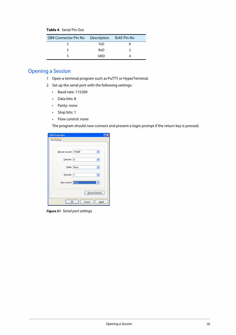
Opening a Session1 Open a terminal program such as PuTTY or HyperTerminal.
2 Set up the serial port with the following settings:
• Baud rate: 115200
• Data bits: 8
• Parity: none
• Stop bits: 1
• Flow control: none
The program should now connect and present a login prompt if the return key is pressed.
Figure 51 Serial port settings
Table 4 Serial Pin Out
DB9 Connector Pin No Description RJ45 Pin No
2 TxD 8
3 RxD 2
5 GND 4
Opening a Session 76
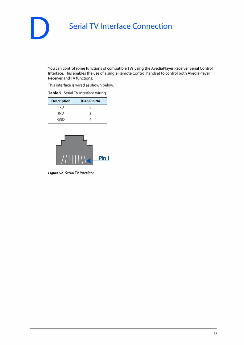
D Serial TV Interface Connection
You can control some functions of compatible TVs using the AvediaPlayer Receiver Serial Control Interface. This enables the use of a single Remote Control handset to control both AvediaPlayer Receiver and TV functions.
This interface is wired as shown below.
Figure 52 Serial TV Interface
Table 5 Serial TV interface wiring
Description RJ45 Pin No
TxD 8
RxD 2
GND 4
77

E Serial Pass-through
To enable serial pass-through, first add a line of the following form to your serial out configuration file:
<telnet port="5001" enable="yes"/>
Then download the file to the receiver as described in Chapter 6, "Configuring TV Control".
You can then use a telnet client to connect to the receiver’s IP address on the specified port. This will give you slave line access to the attached TV.
Example:
<exterity>
<tv>
<config>
<manufacturer name="lg" version="1" />
<serial baud="9600" parity="none" databits="8" flow="none" raw="no" />
<telnet port="5001" enable="yes"/>
</config>
</tv>
</exterity>
To enable/disable serial pass-through or change the TCP port, please consult Table 6.
Table 6
<telnet> attributes Type Description
Port Integer TCP Port to listen on
enable yes | no To enable or disable serial pass through
78

F Support and Contact Information
Technical Support for Exterity products is provided by authorised Systems Integrators and Resellers. Please contact your Systems Integrator or Reseller with any support issues.
79