autosar goes multi-core – the safe way - vector: software · title: autosar goes multi-core –...
TRANSCRIPT

1
Technical Article
July 2014
AUTOSAR goes Multi-core – the safe way
The main reason for introducing multi-core architectures is to
increase the computing power without having to have a higher
clock speed. This is however only possible if enough of the applica-
tion software can be parallelized. The classic reference in this con-
text is Amdahl’s law. Taking a dual core processor and software
with a parallelizability of 50% as an example, this yields a maxi-
mum increase in power of only 30% as compared to a single-core
architecture.
To achieve the best possible computing power, developers have
to make every effort to minimize inter-core resource sharing when
distributing the software modules. The resources concerned are
hardware registers and – in most cases – data areas. The challenge
presented by cross-core resource utilization is not so much access
coordination but rather the avoidance of wait-states in the case of
concurrent access to the shared resources. In such situations there
is a loss of independent data processing and parallelization is not
as useful.
Functional safety as per ISO 26262
Implementation of the functional safety requirements stipulated
by ISO 26262 is now an integral part of the development process in
automotive engineering. The requirements for the functions of an
ECU are assessed with respect to their relevance to safety on the
basis of a hazard and risk analysis and the appropriate ASIL (Auto-
motive Safety Integrity Level) is assigned. What are the conse-
quences for a multi-core software architecture if safety-related
functions have to be implemented? Before answering this question
there are a few points to note with regard to the lockstep concept
for multi-core processors used in many safety projects.
Lockstep mode
In lockstep mode two cores execute the same code. An indepen-
dent comparator compares the results and generates a trap in the
case of a discrepancy. The next step depends on the hardware and
the safety concept of the ECU. The design of the hardware must
ensure that it assumes a safe state following the occurrence of the
trap. Apart from error handling, no multi-core software extensions
are required as both cores execute the same code. In other words:
Even though use is being made of several cores, this is not a multi-
core architecture intended to increase computing power.
Two major topics are currently at the center of software development activities for automotive ECUs: First, the trend in com-puter architecture towards multicore processors and second the safety standards demanded by ISO 26262. Each of these topics is already complex enough in its own right, so what will be the consequences of the two together?
2
Technical Article
July 2014
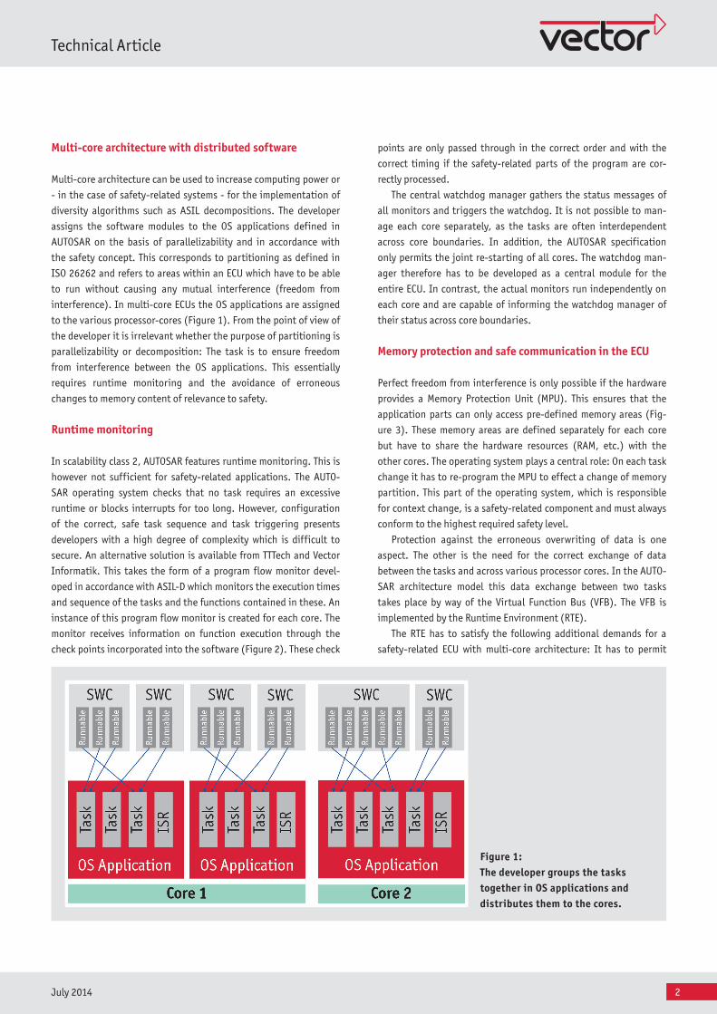
Multi-core architecture with distributed software
Multi-core architecture can be used to increase computing power or
- in the case of safety-related systems - for the implementation of
diversity algorithms such as ASIL decompositions. The developer
assigns the software modules to the OS applications defined in
AUTOSAR on the basis of parallelizability and in accordance with
the safety concept. This corresponds to partitioning as defined in
ISO 26262 and refers to areas within an ECU which have to be able
to run without causing any mutual interference (freedom from
interference). In multi-core ECUs the OS applications are assigned
to the various processor-cores (Figure 1). From the point of view of
the developer it is irrelevant whether the purpose of partitioning is
parallelizability or decomposition: The task is to ensure freedom
from interference between the OS applications. This essentially
requires runtime monitoring and the avoidance of erroneous
changes to memory content of relevance to safety.
Runtime monitoring
In scalability class 2, AUTOSAR features runtime monitoring. This is
however not sufficient for safety-related applications. The AUTO-
SAR operating system checks that no task requires an excessive
runtime or blocks interrupts for too long. However, configuration
of the correct, safe task sequence and task triggering presents
developers with a high degree of complexity which is difficult to
secure. An alternative solution is available from TTTech and Vector
Informatik. This takes the form of a program flow monitor devel-
oped in accordance with ASIL-D which monitors the execution times
and sequence of the tasks and the functions contained in these. An
instance of this program flow monitor is created for each core. The
monitor receives information on function execution through the
check points incorporated into the software (Figure 2). These check
points are only passed through in the correct order and with the
correct timing if the safety-related parts of the program are cor-
rectly processed.
The central watchdog manager gathers the status messages of
all monitors and triggers the watchdog. It is not possible to man-
age each core separately, as the tasks are often interdependent
across core boundaries. In addition, the AUTOSAR specification
only permits the joint re-starting of all cores. The watchdog man-
ager therefore has to be developed as a central module for the
entire ECU. In contrast, the actual monitors run independently on
each core and are capable of informing the watchdog manager of
their status across core boundaries.
Memory protection and safe communication in the ECU
Perfect freedom from interference is only possible if the hardware
provides a Memory Protection Unit (MPU). This ensures that the
application parts can only access pre-defined memory areas (Fig-
ure 3). These memory areas are defined separately for each core
but have to share the hardware resources (RAM, etc.) with the
other cores. The operating system plays a central role: On each task
change it has to re-program the MPU to effect a change of memory
partition. This part of the operating system, which is responsible
for context change, is a safety-related component and must always
conform to the highest required safety level.
Protection against the erroneous overwriting of data is one
aspect. The other is the need for the correct exchange of data
between the tasks and across various processor cores. In the AUTO-
SAR architecture model this data exchange between two tasks
takes place by way of the Virtual Function Bus (VFB). The VFB is
implemented by the Runtime Environment (RTE).
The RTE has to satisfy the following additional demands for a
safety-related ECU with multi-core architecture: It has to permit
Figure 1: The developer groups the tasks together in OS applications and distributes them to the cores.

3
Technical Article
July 2014
operating systems, RTE and program flow monitoring for multi-
core architectures up to ASIL-D.
Generally speaking, multi-core systems are far more complex
than single-core concepts. This need not however apply to configu-
ration of the basic software: Once the software has been distribut-
ed to the processor cores, the remaining configuration work for a
multi-core system is no more difficult than for a single-core archi-
tecture with the aid of optimum tool support. The developer groups
tasks, interrupt service routines, etc. together in containers, the
OS applications and then assigns these to the processor cores (Fig-
ure 1). With the DaVinci Configurator Pro configuration tool from
Vector Informatik this can be done with just a few clicks. The inte-
grated RTE generator automatically takes care of configuring the
correct communication methods (intra-core or inter-core) between
the software modules.
communication across memory partitions and at the same time be
able to distinguish whether a communication path runs across core
boundaries (inter-core) or between two tasks running on the same
core (intra-core). Inter-core data transfer requires additional coor-
dination mechanisms. For this purpose, the operating system pro-
vides the RTE with a function known as IOC (Inter-OS-Application
Communicator). This allows the exchange of data between tasks
and interrupt service routines on various cores.
Use of standard solutions
Ensuring functional safety as defined by ISO 26262 on multi-core
ECUs would therefore appear to be no easy task. It does not how-
ever involve re-inventing the wheel but simply using it correctly.
Vector Informatik and TTTech can provide ECU developers with
Fig ure 2: Together with the check points in the appli-cation, flow monitoring ensures the correct sequence.
Fig ure 3: The memory protection unit ensures that the application parts can only access pre-defined memory areas.
4
Technical Article
July 2014
>> Contact information of the Vector Group: www.vector.com/contact
Dr.-Ing. Helmut Brockhas been with Vector Informatik since 1999 where he works as Operating Systems Product Manager.
Dipl.-Ing. (FH) Joachim Kalmbachhas been with Vector Informatik since 2006 where he works as Product Manager in the Embedded Software sector. His main fields are AUTOSAR and Multi-core.
In other words, a lot of support is already available for multi-
core ECUs in the form of basic software and configuration tools for
example. It is far more difficult to realize good tool support for
creation of the software architecture and distribution of the soft-
ware components to the processor cores. In fact it is usually
restricted to the evaluation of variants. In the foreseeable future,
ECU developers will still be called upon for their expertise and
experience.
Translation of a German publication in Elektronik automotive, June/2014
All Figures:Vector Informatik GmbH
Links:Website Vector: www.vector.com