autonomous navigation results from the mars exploration rover
TRANSCRIPT
Autonomous Navigation Results from the MarsExploration Rover (MER) Mission
Mark Maimone, Andrew Johnson, Yang Cheng, Reg Willson, and Larry Matthies
Jet Propulsion Laboratory, California Institute of Technology4800 Oak Grove Drive, Pasadena, CA, 91109, [email protected]
Abstract. In January, 2004, the Mars Exploration Rover (MER) mission landed two rovers,Spirit and Opportunity, on the surface of Mars. Several autonomous navigation capabilitieswere employed in space for the first time in this mission. In the Entry, Descent, and Land-ing (EDL) phase, both landers used a vision system called the Descent Image Motion Esti-mation System (DIMES) to estimate horizontal velocity during the last 2000 meters (m) ofdescent, by tracking features on the ground with a downlooking camera, in order to controlretro-rocket firing to reduce horizontal velocity before impact. During surface operations,the rovers navigate autonomously using stereo vision for local terrain mapping and a local,reactive planning algorithm called Grid-based Estimation of Surface Traversability Appliedto Local Terrain (GESTALT) for obstacle avoidance. In areas of high slip, stereo vision-based visual odometry has been used to estimate rover motion. As of mid-June, Spirit hadtraversed 3405 m, of which 1253 m were done autonomously; Opportunity had traversed1264 m, of which 224 m were autonomous. These results have contributed substantially tothe success of the mission and paved the way for increased levels of autonomy in futuremissions.
1 Introduction
Searching for signs of fossil or extant life is a major goal of Mars rover explo-ration. Given the central role of water in life as we know it, as well as its likelyroles in the geology, climate, and resource inventory of the planet, “follow thewater” has emerged as a key theme of Mars exploration. The MER mission sentrovers to the Gusev Crater and Meridiani Planum landing sites to attempt to verifythat water had played significant roles in the history of these regions. The missionwas designed for the rovers to be able to traverse about one kilometer in thecourse of a 90 day primary mission, operating for about four hours a day (oneMars day is about 24 hours and 40 minutes). They have far exceeded these goals,both in distance traveled and in lifetime. Given the round-trip communication la-tency between Earth and Mars of 20 minutes or more, this required autonomousnavigation capabilities in the rovers. The Sojourner rover in the 1997 Mars Path-finder mission used structured light for 3-D perception and obstacle avoidancewith an extremely limited onboard computer [1]. With greater computationalpower and the need for more extensive traverse capability, the MER rovers use

Autonomous Navigation Results from MER
stereo vision and a more sophisticated local map and obstacle avoidance algo-rithm. Visual odometry for position estimation was not in the baseline softwaredesign, but was integrated as an “extra credit” item and has grown in importanceas surface operations progressed. The DIMES system for horizontal velocity esti-mation was added late in the mission development phase to address a pressingneed to increase the probability of safe landing. This paper gives an overview ofthe autonomous navigation capabilities of this mission, including the DIMES sys-tem used in EDL (section 2), the rover hardware design (section 3), the rover ste-reo vision and obstacle avoidance system (section 4), and the rover visual odome-try system (section 5). Performance of these systems has generally been verygood; we show examples drawn from surface operations.
2 Descent Image Motion Estimation System (DIMES)
As shown in Fig. 1, after dropping the heat shield, the MER descent systemconsisted of a parachute, the backshell from the interplanetary cruise stage, whichalso held retro-rockets for landing, and the lander itself, which was spooled out ona “bridle” to get it away from the rocket plumes. The retro-rockets (“RADs”, forrocket assisted descent) were designed to bring the vertical velocity to zero 10 to20 m above the surface, after which the bridle was cut and the lander’s fall wascushioned with airbags. The backshell also incorporated a Transverse ImpulseRocket System (TIRS), which could fire laterally to ensure that the backshell wasvertical before RAD firing, so that the RADs did not add to horizontal velocity.
Fig. 1. MER descent system. Left: artist’s illustration of the parachute, backshell,and lander in the last few km of descent. Right: photo of the underside of thelander, before integrating the heat shield.
During mission development, the EDL design team learned that steady-statewinds near the martian surface could induce a lander horizontal velocity that

M. Maimone, A. Johnson, Y. Cheng, R. Willson, and L. Matthies
might result in impact forces exceeding the strength of the airbags. The TIRS sys-tem could be adapted to tilt the backshell so that the RADs could offset the windshear, if a horizontal velocity measurement was available. At the time this waslearned, it was too late to incorporate a traditional doppler radar velocity sensor;however, it was possible to add a downlooking camera and software to use thecamera to track terrain features to estimate the horizontal velocity. We brieflysummarize the algorithm design of that system here; more detail appears in [2].
Fig. 2. DIMES results from the Spirit landing at Gusev Crater: (a) first descentimage with selected features shown as the red squares; (b) second descent imagewith the matched features shown as the green squares; (c) second image again,showing the second set of selected features; (d) third image showing the matchedfeatures from the second image. All feature matches were correct.
The lander had an inertial measurement unit (IMU) and a radar altimeter thatcould measure angular velocity and vertical velocity. Thus, in principle, trackingone feature through two images would add enough information to estimate the en-tire velocity vector. Using just one feature is not very reliable, of course, but theonboard computer was too slow to do much more than this in real-time during de-
Autonomous Navigation Results from MER
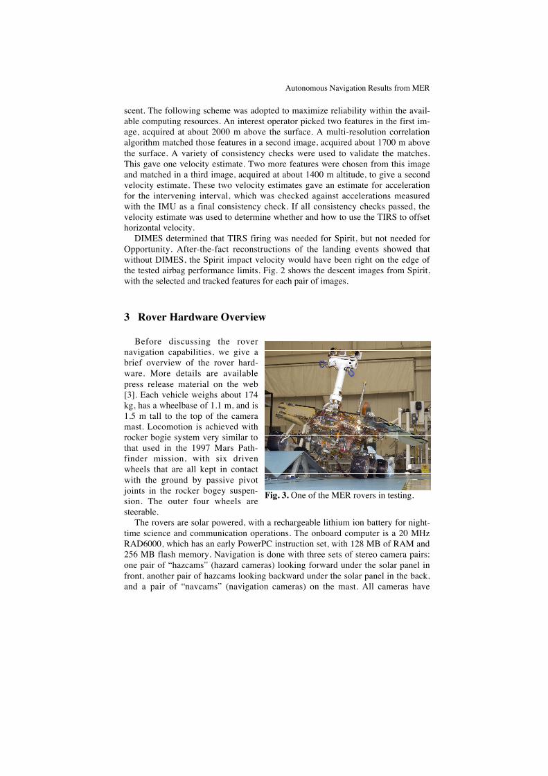
Fig. 3. One of the MER rovers in testing.
scent. The following scheme was adopted to maximize reliability within the avail-able computing resources. An interest operator picked two features in the first im-age, acquired at about 2000 m above the surface. A multi-resolution correlationalgorithm matched those features in a second image, acquired about 1700 m abovethe surface. A variety of consistency checks were used to validate the matches.This gave one velocity estimate. Two more features were chosen from this imageand matched in a third image, acquired at about 1400 m altitude, to give a secondvelocity estimate. These two velocity estimates gave an estimate for accelerationfor the intervening interval, which was checked against accelerations measuredwith the IMU as a final consistency check. If all consistency checks passed, thevelocity estimate was used to determine whether and how to use the TIRS to offsethorizontal velocity.
DIMES determined that TIRS firing was needed for Spirit, but not needed forOpportunity. After-the-fact reconstructions of the landing events showed thatwithout DIMES, the Spirit impact velocity would have been right on the edge ofthe tested airbag performance limits. Fig. 2 shows the descent images from Spirit,with the selected and tracked features for each pair of images.
3 Rover Hardware Overview
Before discussing the rovernavigation capabilities, we give abrief overview of the rover hard-ware. More details are availablepress release material on the web[3]. Each vehicle weighs about 174kg, has a wheelbase of 1.1 m, and is1.5 m tall to the top of the cameramast. Locomotion is achieved withrocker bogie system very similar tothat used in the 1997 Mars Path-finder mission, with six drivenwheels that are all kept in contactwith the ground by passive pivotjoints in the rocker bogey suspen-sion. The outer four wheels aresteerable.
The rovers are solar powered, with a rechargeable lithium ion battery for night-time science and communication operations. The onboard computer is a 20 MHzRAD6000, which has an early PowerPC instruction set, with 128 MB of RAM and256 MB flash memory. Navigation is done with three sets of stereo camera pairs:one pair of “hazcams” (hazard cameras) looking forward under the solar panel infront, another pair of hazcams looking backward under the solar panel in the back,and a pair of “navcams” (navigation cameras) on the mast. All cameras have
M. Maimone, A. Johnson, Y. Cheng, R. Willson, and L. Matthies
1024x1024 pixel CCD arrays that create 12 bit greyscale images. The hazcamshave a 126 degree field of view (FOV) and baseline of 10 cm; the navcams have a45 degree FOV and baseline of 20 cm [4]. Each rover has a five degree of freedomarm in front which carries a science instrument payload with a microscopicimager, Mossbauer spectrometer, alpha/proton/x-ray backscatter spectrometer(APXS), and a rock abrasion tool (RAT). The camera mast has two additional sci-ence instruments: a stereo pair of “pancams” (panoramic cameras) and the “mini-TES” (thermal emission spectrometer). The pancams have filter wheels for mul-tispectral visible and near-infrared imaging for mineral classification. They havethe highest angular and range resolution of all cameras on the rover, with a 16 de-gree field of view and 30 cm baseline. The mini-TES acquires 167 bands between5 and 29 µm in a single pixel. All cameras on the mast and the mini-TES arepointable by pan/tilt motors.
4 Obstacle Detection and Avoidance
The long round-trip communication latency between Earth and Mars andscheduling constraints on the Deep Space Network make it difficult to controllong distance rover traverses from Earth, which necessitates some degree of on-board autonomous navigation to improve operational efficiency, reduce operationscost, and increase mission safety. However, the limited onboard computing power,the need for safety, and other factors constrain the level of sophistication in thealgorithms that can be put onboard. Owing to budget and schedule constraints, thebaseline autonomous navigation system includes only local obstacle avoidancewith stereo vision; that is, there are no onboard global mapping, global path plan-ning, or global localization functions. Stereo vision is used as the range sensor forobstacle avoidance because mature algorithms and reasonably compact, low-power, flight-qualified cameras are available for this, whereas flight-qualified ver-sions of alternate sensors (e.g. ladar) with acceptable performance and form factorwere not available.
4.1 Stereo Vision
Details of the stereo algorithm are described in [5]; here we give a brief over-view of the algorithm, discuss some details that are specific to the MER imple-mentation, and discuss its performance on Mars.
The stereo algorithm is a typical area-based algorithm using the sum of abso-lute differences (SAD) criterion for matching. Due to very slow readout from theflight cameras (about 5 seconds per frame for full resolution, 1024x1024 pixel im-agery), images are generally binned vertically within the CCD cameras and readout at 256x1024 pixel resolution. This is reduced by averaging to 256x256. Stereomatching is then performed at 256x256 resolution. The images are rectified andbandpass filtered before the SAD operation, a variety of stereo matching consis-
Autonomous Navigation Results from MER
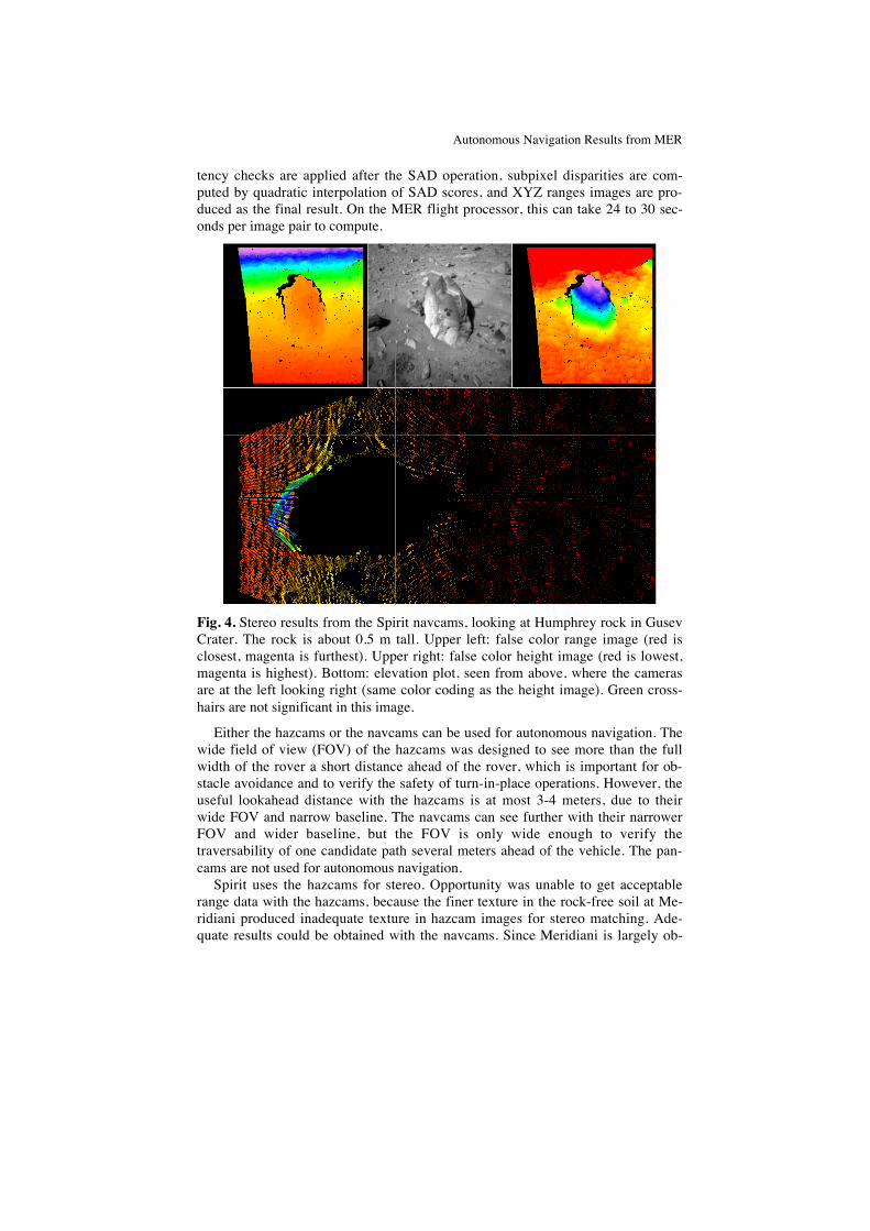
tency checks are applied after the SAD operation, subpixel disparities are com-puted by quadratic interpolation of SAD scores, and XYZ ranges images are pro-duced as the final result. On the MER flight processor, this can take 24 to 30 sec-onds per image pair to compute.
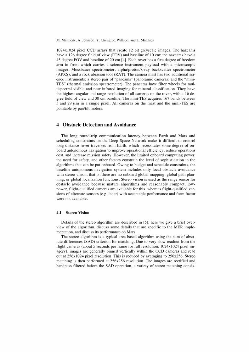
Fig. 4. Stereo results from the Spirit navcams, looking at Humphrey rock in GusevCrater. The rock is about 0.5 m tall. Upper left: false color range image (red isclosest, magenta is furthest). Upper right: false color height image (red is lowest,magenta is highest). Bottom: elevation plot, seen from above, where the camerasare at the left looking right (same color coding as the height image). Green cross-hairs are not significant in this image.
Either the hazcams or the navcams can be used for autonomous navigation. Thewide field of view (FOV) of the hazcams was designed to see more than the fullwidth of the rover a short distance ahead of the rover, which is important for ob-stacle avoidance and to verify the safety of turn-in-place operations. However, theuseful lookahead distance with the hazcams is at most 3-4 meters, due to theirwide FOV and narrow baseline. The navcams can see further with their narrowerFOV and wider baseline, but the FOV is only wide enough to verify thetraversability of one candidate path several meters ahead of the vehicle. The pan-cams are not used for autonomous navigation.
Spirit uses the hazcams for stereo. Opportunity was unable to get acceptablerange data with the hazcams, because the finer texture in the rock-free soil at Me-ridiani produced inadequate texture in hazcam images for stereo matching. Ade-quate results could be obtained with the navcams. Since Meridiani is largely ob-
M. Maimone, A. Johnson, Y. Cheng, R. Willson, and L. Matthies
stacle-free, it has been sufficient to use navcam stereo to check the traversabilityof the nominal path forward and stop the vehicle if a hazard is detected.
Fig. 4 shows sample stereo results from the Spirit navcams looking at a rockthat was studied by the science team.
4.2 GESTALT
The GESTALT obstacle avoidance algorithm is also described in detail in [5];here we give a brief overview and discuss implementation and performance issuesspecific to MER. A higher level description of the overall rover driving softwarearchitecture appears in [6].
Range images from stereo are converted to “goodness” or “traversability” mapswith 20 cm cells in a 10x10 m grid centered on the rover. For each range image,the complete set of range points is analyzed for traversability by fitting planarpatches centered on each map cell in turn, where each patch is a circle with thediameter of the rover (nominally 2.6 m). The surface normal, RMS residual, andminimum and maximum elevation difference from the best fit plane determine a“goodness” factor for that map cell that characterizes its traversability. Goodnessmaps from each range image are registered and accumulated over time with theusual modulo map indexing arithmetic to avoid the need to scroll map data to keepthe map bounded. Where new data overlaps old data, the new data overwrites theold data in the map. The merged goodness map is then used to evaluatetraversability of a fixed set of candidate steering trajectories, which are circulararcs of varying radius. 23 forward arcs, 23 backward arcs, and two point turns areevaluated in each driving cycle. Evaluation amounts to adding up the goodnessscores along each arc, with nearby cells given higher weight. The result is a set oftraversability votes for all arcs. These votes are input to an arbiter, which alsotakes input from waypoints provided by human operators during mission planning.The rover drives a fixed distance along the winning arc before stopping to acquirenew images for the next driving cycle. The distance per cycle is set by human op-erators at anywhere from 35 cm to 1 m or more depending a variety of operationalfactors, including terrain difficulty and overall distance goals for the day.
Typical computing time per cycle of GESTALT is around 70 seconds. Whilethe rover is driving, its peak speed is 5 cm/sec, but it is typically operated at lessthan that (3.75 cm/sec) for power reasons. With computing time, the median netdriving speed was about 0.6 cm/sec. Because this is so slow and the science teamdesired to cover large distances to Endurance Crater and the Columbia Hills, a hy-brid daily driving scheme was designed in which human operators use navcam andpancam stereo imagery to plan each day’s traverse manually as far as they can seeit to be safe. The rover drives this segment blindly, then switches to autonomousnavigation to drive for whatever time remains in the day. Blind drives can be sev-eral 10’s of meters. The maximum daily traverse for Spirit up to June 14, 2004,was 124 m, of which 62 m were autonomous.
After some tuning of the algorithm to overcome excessively conservative be-havior at slope changes, GESTALT has performed well. Fig. 5 shows some results

Autonomous Navigation Results from MER
of obstacle avoidance from Spirit. The terrain on the plains at Meridiani was be-nign enough that the only “obstacles” were occasional hollows from small, in-filled craters. Within Eagle and Endurance Craters at Meridiani, the main naviga-tion issues were slopes and slippage, not obstacles per se.
Fig. 5. GESTALT results from Spirit. Top: two examples of daily traverse plotsthat started with blind drives and ended with autonomous portions that includedsome rock avoidance maneuvers, covering total distances of 70.9 m (left) and 92.4m (right). Bottom: a mosaic of navcam imagery looking back on a day’s traversethat ended with some rock avoidance, as can be seen from the rover tracks.
5 Visual Odometry
In routine operation, onboard position estimation is done by dead reckoningwith the wheel encoders and IMU, with occasional heading updates by sun sens-ing with the pancams. Long distance localization is done on Earth using bundleadjustment from manually matched tie points in panoramic imagery [7]. On theplains at Gusev Crater, interpreting the bundle adjustment results as nominalground truth, dead reckoning errors have been only a few percent of distance over
M. Maimone, A. Johnson, Y. Cheng, R. Willson, and L. Matthies
several kilometers of travel. However, both rovers have experienced large slippageon slopes in the Columbia Hills, Eagle Crater, and Endurance Crater; in fact, up to125% in one case in the Columbia Hills (ie. the rover slipped backwards in an at-tempted forward drive). Slip is becoming a bigger issue for Spirit as it attempts todrive with one wheel locked, due to likely imminent failure of that wheel’s drivemotor. Stereo vision-based visual odometry is part of the flight software, but wasnot routinely used in most of the mission to maximize driving speed. It has beenused to assess slippage of Opportunity in Eagle Crater and is now being used bySpirit to measure and counter the effects of slip on slopes and of dragging thelocked wheel.
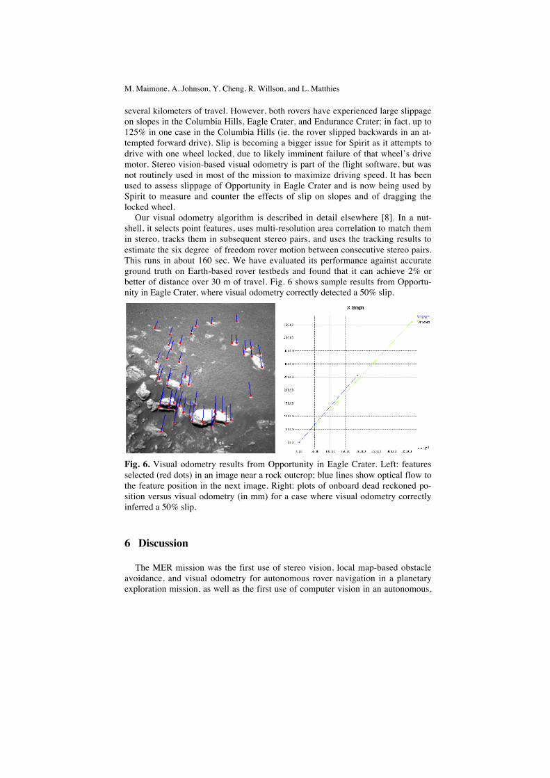
Our visual odometry algorithm is described in detail elsewhere [8]. In a nut-shell, it selects point features, uses multi-resolution area correlation to match themin stereo, tracks them in subsequent stereo pairs, and uses the tracking results toestimate the six degree of freedom rover motion between consecutive stereo pairs.This runs in about 160 sec. We have evaluated its performance against accurateground truth on Earth-based rover testbeds and found that it can achieve 2% orbetter of distance over 30 m of travel. Fig. 6 shows sample results from Opportu-nity in Eagle Crater, where visual odometry correctly detected a 50% slip.
Fig. 6. Visual odometry results from Opportunity in Eagle Crater. Left: featuresselected (red dots) in an image near a rock outcrop; blue lines show optical flow tothe feature position in the next image. Right: plots of onboard dead reckoned po-sition versus visual odometry (in mm) for a case where visual odometry correctlyinferred a 50% slip.
6 Discussion
The MER mission was the first use of stereo vision, local map-based obstacleavoidance, and visual odometry for autonomous rover navigation in a planetaryexploration mission, as well as the first use of computer vision in an autonomous,

Autonomous Navigation Results from MER
real-time function (horizontal velocity estimation) during landing in a planetarymission. The algorithms are competent and emphasize reliability within the con-straints a very slow onboard computer. Algorithms for analogous functions onEarth-based research vehicles can have more sophistication because of the muchgreater computing resources often available, but are rarely, if ever, designed ortested to reach the same level of fault tolerance. These algorithms have performedwell and contributed to the success of the mission; in particular, DIMES may havesaved Spirit from a disastrous landing.
In this mission, the most valuable science results have been found in rock out-crops in sloping, slippery terrain, either inside craters or on hills; moreover, therovers have had to drive much further than anticipated prior to landing to reachsuch outcrops. Thus, for future missions, key issues include increasing the speedof the vision and planning algorithms and integrating visual odometry inside thedriving and steering loop to enable safe, efficient traversal on slippery terrain. In-corporating path planning algorithms for longer lookahead and rougher terrain willalso be valuable. For landers, the focus of vision algorithm research will switch toenabling precision landing.
References
[1] Wilcox, B., and Nguyen, T. Sojourner on Mars and Lessons Learned for Fu-ture Planetary Rovers. 28th Int’l Conf. on Environmental Systems, Danvers,MA, July 1998.
[2] Cheng, Y., Goguen, J., Johnson, A., Leger, C., Matthies, L., San Martin, M.,and Willson, R. The Mars Exploration Rovers Descent Image Motion Esti-mation System. IEEE Intelligent Systems Magazine, May/June 2004.
[3] http://marsrovers.jpl.nasa.gov/newsroom/presskits.html.[4] Maki, J., et al. Mars Exploration Rover Engineering Cameras. Journal of
Geophysical Research, vol. 108 E12, December 2003.[5] Goldberg, S., Maimone, M., and Matthies, L. Stereo Vision and Rover Navi-
gation Software for Planetary Exploration. IEEE Aerospace Conference, BigSky, Montana, March 2002.
[6] Maimone, M. and Biesiadicki, J. The Mars Exploration Rover Surface Mo-bility Flight Software: Driving Ambition. IEEE Aerospace Conference, BigSky, Montana, March 2005.
[7] Li, R., Di, K., Matthies, L., Arvidson, R., Folkner, W., Archinal, B. RoverLocalization and Landing Site Mapping Technology for the 2003 Mars Ex-ploration Rover Mission. Journal of Photogrammetric Engineering and Re-mote Sensing, January 2004.
[8] Olson, C., Matthies, L., and Schoppers, M. Rover Navigation using StereoEgo-motion. Robotics and Autonomous Systems, 43(4), June 2003.