automatic pipe flushing rig gineering for shipboard piping ... · pdf...
TRANSCRIPT

August 1992NSRP 0355I COMMITTEE
ESL EFFECTS NATIONALN AND COATINGS SHIPBUILDING
INTEGRATION RESEARCHOURCES PROGRAM STANDARDS
●*NGGINEERING0N
Automatic Pipe Flushing Rigfor Shipboard Piping Systems
U.S. DEPARTMENT OF TRANSPORTATIONMaritime Administration and the U.S. Navy
in cooperation with
National Steel and Shipbuilding CompanySan Diego, California

Report Documentation Page Form ApprovedOMB No. 0704-0188
Public reporting burden for the collection of information is estimated to average 1 hour per response, including the time for reviewing instructions, searching existing data sources, gathering andmaintaining the data needed, and completing and reviewing the collection of information. Send comments regarding this burden estimate or any other aspect of this collection of information,including suggestions for reducing this burden, to Washington Headquarters Services, Directorate for Information Operations and Reports, 1215 Jefferson Davis Highway, Suite 1204, ArlingtonVA 22202-4302. Respondents should be aware that notwithstanding any other provision of law, no person shall be subject to a penalty for failing to comply with a collection of information if itdoes not display a currently valid OMB control number.
1. REPORT DATE AUG 1992
2. REPORT TYPE N/A
3. DATES COVERED -
4. TITLE AND SUBTITLE Automatic Pipe Flushing Rig for Shipboard Piping Systems
5a. CONTRACT NUMBER
5b. GRANT NUMBER
5c. PROGRAM ELEMENT NUMBER
6. AUTHOR(S) 5d. PROJECT NUMBER
5e. TASK NUMBER
5f. WORK UNIT NUMBER
7. PERFORMING ORGANIZATION NAME(S) AND ADDRESS(ES) Naval Surface Warfare Center CD Code 2230-Design Integration ToolsBldg 192, Room 128 9500 MacArthur Blvd, Bethesda, MD 20817-5700
8. PERFORMING ORGANIZATIONREPORT NUMBER
9. SPONSORING/MONITORING AGENCY NAME(S) AND ADDRESS(ES) 10. SPONSOR/MONITOR’S ACRONYM(S)
11. SPONSOR/MONITOR’S REPORT NUMBER(S)
12. DISTRIBUTION/AVAILABILITY STATEMENT Approved for public release, distribution unlimited
13. SUPPLEMENTARY NOTES
14. ABSTRACT
15. SUBJECT TERMS
16. SECURITY CLASSIFICATION OF: 17. LIMITATION OF ABSTRACT
SAR
18. NUMBEROF PAGES
139
19a. NAME OFRESPONSIBLE PERSON
a. REPORT unclassified
b. ABSTRACT unclassified
c. THIS PAGE unclassified
Standard Form 298 (Rev. 8-98) Prescribed by ANSI Std Z39-18

DISCLAIMER
These reports were prepared as an account of government-sponsored work.
Neither the United States, nor the Maritime Administration, nor any person
acting on behalf of the Maritime Administration, (A) makes any warranty or
representation, expressed or implied, with respect to the accuracy,
completeness or usefulness of the information contained in this report/
manual, or that the use of any information, apparatus, method, or process
disclosed in this report may not infringe privately owned rights; or (B)
assumes any liabilities with respect to the use of or for damages resulting
from the use of any information, apparatus, method, or process disclosed
in the report. As used in the above, Persons acting on behalf of the
Maritime Administration” includes any employee, contractor, or subcontractor
to the contractor of the Maritime Administration to the extent that such
employee, contractor, or subcontractor to the contractor prepares, handles,
or distributes, or provides access to any information pursuant to his
employment or contract or subcontract to the contractor with the Maritime
Administration. ANY POSSIBLE IMPLIED WARRANTIES OF MERCHANTABILITY
AND/OR FITNESS FOR PURPOSE ARE SPECIFICALLY DISCLAIMED.

FINAL REPORT
AUTOMATIC PIPE FLUSHING RIG
FOR
SHIPBOARD PIPING SYSTEMS
SP-1-83-6
TO
SNAME/SHIP PRODUCTION COMMITTEEPANEL SP-1
FACILITIES AND ENVIRONMENTAL EFFECTS
BY
NATIONAL STEEL AND SHIPBUILDING COMPANYSAN DIEGO, CALIFORNIA
CONTENTS
FOREWORD
INTRODUCTION
CONCEPT
PARAMETERS
PRODUCTION FLUSH
RECOMMENDATIONS
ADDENDUM
PROJECT CONCLUSIONS
APPENDIXA. AUTO FLUSH RIG OPERATION DISCUSSIONB. HYDE PRODUCTS, INC REPORTC. BEELCO COMPUTER PROGRAM DESCRIPTIONC. BEELCO COMPUTER SET POINT SELECTIOND. FLUSH DOCUMENTATION
FOX STEERING GEARPFIEFER LUBE OIL PIPING
1
2
3
4
5
5
6
6

SP-1-83-6Automatic Pipe Flush RigForShipboard Piping System Flushing
FOREWORD
Piping systems flushing is a most common task in any newconstruction or ship repair. The work is time consuming andlabor intensive as well as schedule-impacting. In theabsence of the possibility of deleting the process complete-ly, this Project was devised to 1) Decrease the labor con-tent for the task, and 2) Shorten the time cycle for com-pleting and verifying the flush certification.
Additionally, the project was designed to have universal ap-plication throughout American shipyards. The merits of thistype of NSRP Project, while remaining unglamorous and lack-ing super technology, are never-the-less at the heart of theintention to improve productivity.
The project does utilize current small computer applicationand high quality filtration techniques to accomplish the ob-jectives. Therefore, the effort is certainly.within currenttechnology.
The original efforts of Mr.Ed Southern of Todd LA, the con-tinual participation of Mr.Bill Nell and Hyde Products thro-ughout, and the work of Mr.Gary Hobson of NASSCO were vitalto the effort. Many THANK YOU’s go to all who contributed.
1

INTRODUCTION
This project had its origin in a Todd Shipyard of LosAngeles study of PIPE SYSTEM FLUSHING, SP-1-83-1O. The dataderived from the study indicated that the labor content andschedule cycle time to complete the work were significant.If an automated flushing method for shipboard systems weredeveloped and successfully tested some real productivityincrease would be accomplished.
The concept for this study and project had been proposed andapproved in the 1983 program but was contingent upon the re-sults of SP-1-83-1O.
In the fall of 1986, Hyde Products of Cleveland, Ohioentered the project to develop a rig that would control,monitor, and report a system flush. This work was done.However, a period of uncertainty for the project ensued whenTodd closed the LA operation.
National ,Steel and Shipbuilding CO of San Diego, CA took re-sponsibility for the completion of the project in November,1989. This work focused on the Testing of the automated rigin a shipboard system flush and the completion of the pro-ject including the final reports and publication. A contractwas made with Hyde to continue their participation and aschedule and plans were developed for an actual productionflush at NASSCO.
What had been scheduled as the final oral report to the SP-1group was made at the 0ctober,1990 meeting at Groton, CT.Due to the test results, the positive findings, and unani-mous agreement of the participants, it was recommended tothe Panel that modifications and additional testing beundertaken. Therefore the final report was issued as aninterim report with the addendum work to follow. The finalpublished report contains the results and conclusions of theextended project work.
2

CONCEPT
In March of 1986, Project SP-1-83-1O PIPE SYSTEMS FLUSHINGSTUDY, was completed by Todd LA. One of the key recommen-dations in the final report was the design, building, andshipboard testing of an automated flushing rig.
The benefits to be derived from this project would be:1. Reduction in the cycle time to perform a flush and
verify the criteria data for a clean system.2. Reduction of man hours needed to perform a flush.3. Utilize current technology by providing computerized
controls, read-outs, and print-outs to accomplishthe above.
4. Universal application to American shipyards in gen-eral.
The normal operation of an on-board system flush has hist-orically required long time cycles in which laboratory datawould be provided (often more than once, even several times)before a system met the "clean criteria" of the specifica-tions. This of course impacted scheduling of work since itwas not possible to proceed with tearing down the flush set-up to make way for sequenced work to which the flush wasprerequisite.
Many man hours have historically been required to set-up thepiping for the flush along with the pump, filtering andmetering devices required. The work also required more man-ning than what would be justified for the flush operationalone, to deal with system leaks and potential leaks.
By utilizing the technology of the small computer, was itpossible to reduce both causes of inefficiency, and increaseproductivity and lower direct cost? If a control systemcould monitor the measured parameters of the flush andaccurately measure "cleanness",the flush would only be aslong as absolutely needed and the certification would bepredictable with in a very narrow window of error.
It has always been the objective of NSRP to provide projectswith application to industry wide benefit. Regrettably, thiscould not always be the case due to the diverse nature ofshipyards and the related work. Therefore, it appeared to bean added potential return, that this project had the solidpossibility of universal application.
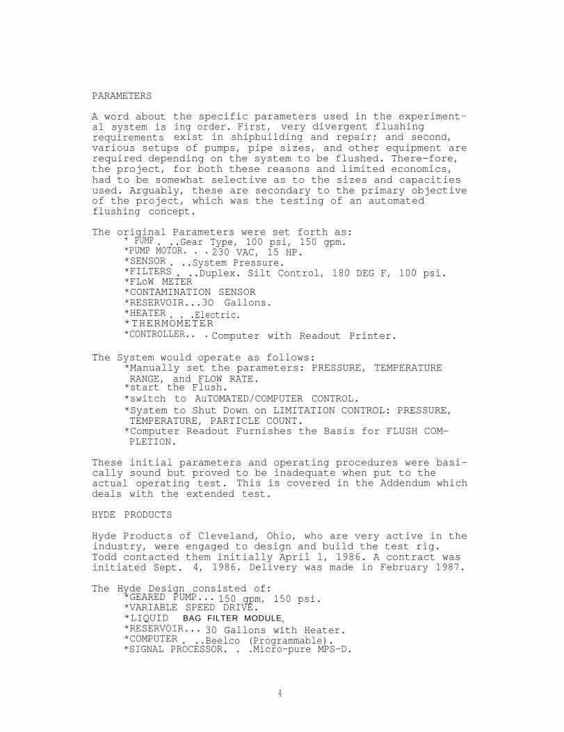
PARAMETERS
A word aboutal system isrequirements
the specific parameters used in the experiment-ing order. First, very divergent flushingexist in shipbuilding and repair; and second,
various setups of pumps, pipe sizes, and other equipment arerequired depending on the system to be flushed. There-fore,the project, for both these reasons and limited economics,had to be somewhat selective as to the sizes and capacitiesused. Arguably, these are secondary to the primary objectiveof the project, which was the testing of an automatedflushing concept.
The original Parameters were set forth as:* PUMP . ..Gear Type, 100 psi, 150 gpm.*PUMP MOTOR. . . 230 VAC, 15 HP.*SENSOR . ..System Pressure.*FILTERS . ..Duplex. Silt Control, 180 DEG F, 100 psi.*FLoW METER*CONTAMINATION SENSOR*RESERVOIR...3O Gallons.*HEATER . . .Electric.*THERMOMETER *CONTROLLER.. . Computer with Readout Printer.
The System would operate as follows:*Manually set the parameters: PRESSURE, TEMPERATURERANGE, and FLOW RATE.*start the Flush.*switch to AuTOMATED/COMPUTER CONTROL.*System to Shut Down on LIMITATION CONTROL: PRESSURE,TEMPERATURE, PARTICLE COUNT.*Computer Readout Furnishes the Basis for FLUSH COM-PLETION.
These initial parameters and operating procedures were basi-cally sound but proved to be inadequate when put to theactual operating test. This is covered in the Addendum whichdeals with the extended test.
HYDE PRODUCTS
Hyde Products of Cleveland, Ohio, who are very active in theindustry, were engaged to design and build the test rig.Todd contacted them initially April 1, 1986. A contract wasinitiated Sept. 4, 1986. Delivery was made in February 1987.
The Hyde Design consisted of:*GEARED PUMP... 150 gpm, 150 psi.*VARIABLE SPEED DRIVE.*LIQUID BAG FILTER MODULEe
*RESERVOIR... 30 Gallons with Heater.*COMPUTER . ..Beelco (Programmable).*SIGNAL PROCESSOR. . .Micro-pure MPS-D.
4
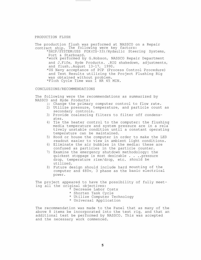
PRODUCTION FLUSH
The production flush was performed at NASSCO on a Repaircontract ship. The following were key factors:
*SHIP/SYSTEM:USS FOX(CG-33)/Hydaulic Steering Systems,Port & Starboard.*work performed by G.Hobson, NASSCO Repair Departmentand J.Fife, Hyde Products. .RIG shakedown, adjustments,and flush..August 13-17, 1990.*US Navy acceptance of PCP (Process Control Procedure)and Test Results utilizing the Project Flushing Rigwas obtained without problem.*FIUSh Cycle Time was 1 HR 45 MIN.
CONCLUSIONS/RECOMMENDATIONS
The following were the recommendations as summarized byNASSCO and Hyde Products:
1)2)
3)
4)
5)
6)
7)
8)
Change the primary computer control to flow rate.Utilize pressure, temperature, and particle count assecondary controls.Provide coalescing filters to filter off condens-ates.Tie the heater control to the computer: the flushingmedia temperature and system pressure are in a rela~
tively unstable condition until a constant operatingtemperature can be maintained.Hood or house the computer in order to make the LEDreadout easier to view in ambient light conditions.Eliminate the air bubbles in the media: these areconfused as particles in the particle counter.Examine the emergency shutdown methodology: thequickest stoppage is most desirable . . ..pressuredrop, temperature rise/drop, etc.utilized.Future design should include hardcomputer and 480v, 3 phase as thepower.
should be
mounting of thebasic electrical
The project appeared to have the possibility of fully meet-ing all the original objectives:
* Decrease Labor Costs* Shorten Task Cycle* Utilize Computer Technology* Universal Application
The recommendation was made to the Panel that as many of theabove 8 items be incorporated into the test rig, and that anadditional test be performed by NASSCO. This was acceptedand the necessary work commenced.

ADDENDUM
Following approval to proceed with the work as outlined inthe report to the panel meeting at Groton, CT in October’90,the modifications and re-test were undertaken. This work wascompleted on March 20, 1992 with the successful productionflush of the Matson PFIEFER lube oil piping at NASSCO.
The following is a summary of up to date comments concerningthe recommendations (refer to Page 5) made following thefirst test:
1) The computer was changed to flow rate as the primarycontrol. This worked quite well.
2) Using pressure, temperature, and particle count assecondary controls also worked well.
3) The cost associated with adding coalescing filterswas not within the resources. This item has been in-corporated in the Phase II project proposed for ’93.
4) The heater control was tied to the computer andfunctionally tested. However, a heating systemwas not required in the actual PFIEFER on boardflush.
5) The LED read-out was hooded to make it easier toread. The ultimate solution to the variations inambient working light is related to hardware andsystems design.
6) Elimination of the air bubbles in the media provedto be a situation beyond the scope of the projectresources and has been incorporated in the Phase IIproject proposal.
7) The Emergency Shutdown methods appear to be adequateby employing the control parameters of the system:Pressure and flowrate controls.
8) The need for appropriate electrical power provisionsmust be a primary design parameter. Future systemsshould have primary voltage of 480 v.,3-, which canbe stepped down.
PROJECT CONCLUSIONS AND DISCUSSION
The use of the automated flush rig in the 2 project testsproduced indications that the desired objectives can be at-tained and that production design for automated rig functionand control should be pursued.
1) The labor used in a flush can be reduced 40% to 90%depending upon current yard practice, contract spec-ifications, and various other conditions.
2) The flush duration can be reduced 30% to 50% orpossibly more.
3) Direct computer reporting of the “cleanness’ datacan be developed. This was not fully accomplishedin this “test" rig which was limited to the countingof a "set" micron size rather than a range of counts
6

for a range of micron sizes. A set of softwareroutines must be developed.
4) The possibility that all yards might want to pursuethis technology remains a question for the individ-ual yard, however, there are no extraordinary eco-nomic barriers. A system comparable to the test rigwould cost $25,000. to $35,000.
The main limitations to the “test" rig, as previously stat-ed, were that a wide range of system piping sizes, media,and other criteria were not feasible. This was .a true "con-cept model” with various compromises. These are:
1) It has a physical configuration that is not modular.It can be used only on small diameter pipe systemsat 150 GPM flow rate.
2) The computer system is 5 year old vintage.3) It is not applicable to retrofit and universal use.
A production design would use state of the art com-puter hardware and software, be totally modular, andpossess retrofit capability for existing systems.
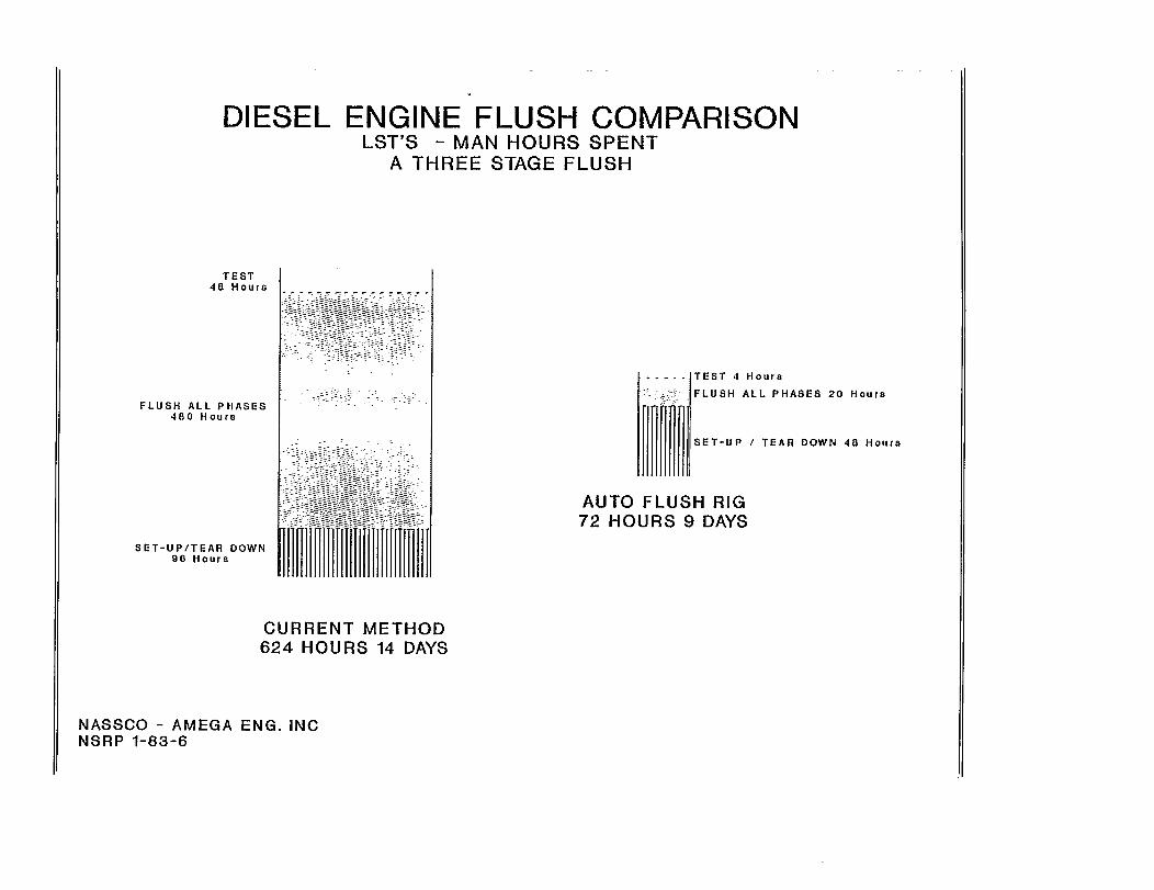
A study was made as a post-project evaluation in order toadd emphasis to the various conclusions. The work was con-ducted in conjunction with the NASSCO Machinery Department,which did the actual testing of the rig on both the FOX andthe PFIEFER. The details of the study are contained in theAppendix.
The experience with the project tests was applied to an LSTdiesel engine flush with which the department is very famil-iar. The graph on the next page shows the expected resultsif the automated technology and methodology were used inplace of the current practice.
FLUSH ACTIVITY REDUCTION------------------------- -----------
Test(MN HRS) 91.7%Flush All Phases(MN HRS) 95.8%Setup/Tear Down(MN HRS) 50.0%
Duration(DAYS) 35.7%
It can be seen that the impact on costs and schedule will bewell worth this effort, even at 50% of these possibilities.
7

APPENDIX A.
AUTO FLUSH OPERATION DISCUSSION

Auto Flush Operation DiSCUSSIONs
Scope: To explain the tasks involved with the operation of theAuto Flush Rig.
Tasks
1. Set-up / Tear Down:
The times would depend on what type of system was beingflushed. There are one,two, and three stage flushes. Anexample would be: a steam turbine and reduction gear (MainEngine) require a two stage flush; bypassing the bearingsand heat exchanger on the first stage, then flushing thesystem as a whole including the heat exchanger and bearings,after it was ascertained that the first stage was clean.Another example are the diesel engines on the LST’s, theserequire a three stage flush.
A. Flush System Build-up Duration Hours
* Small Flush: 1 Day 4 Hours
* Normal Flush: 1 Day 24 Hours
* Reduction Gear: 1 Day 36 Hours
* Diesel Engine: 1 Day 24 Hours
B. Tear Down
* Small Flush: 1 Day 4 Hours
* Normal Flush: 1 Day 16 Hours
* Reduction Gear: 1 Day 36 Hours
* Diesel Engine: 1 Day 24 Hours
C. Size Variance Factor - The larger the flush the morethe work content. Below is a range of typical pipesizing by flush type.
* Small Flush: 1/2” to 1 1/4” pipe
* Normal Flush: 1 1/2” to 3“ pipe
* Reduction Gear: 4“ to 8" pipe
* Diesel Engine: 4“ to 10” pipe
1
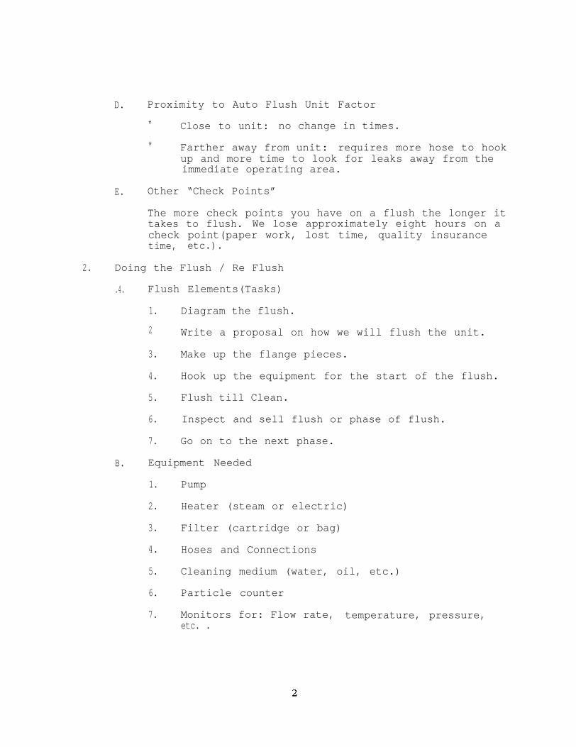
D. Proximity to Auto Flush Unit Factor
* Close to unit: no change in times.
* Farther away from unit: requires more hose to hookup and more time to look for leaks away from theimmediate operating area.
E. Other “Check Points”
The more check points you have on a flush the longer ittakes to flush. We lose approximately eight hours on acheck point(paper work, lost time, quality insurancetime, etc.).
2. Doing the Flush / Re Flush
.4. Flush Elements(Tasks)
1. Diagram the flush.
2 Write a proposal on how we will flush the unit.
3. Make up the flange pieces.
4. Hook up the equipment for the start of the flush.
5. Flush till Clean.
6. Inspect and sell flush or phase of flush.
7. Go on to the next phase.
B. Equipment Needed
1. Pump
2. Heater (steam or electric)
3. Filter (cartridge or bag)
4. Hoses and Connections
5. Cleaning medium (water, oil, etc.)
6. Particle counter
7. Monitors for: Flow rate, temperature, pressure,etc. .

C. Filter Types:
1. Cartridge 1 to 25 micron
2. Bag Filter Nylon
3. Bag Filter Muslin
4. Bag Filter Polyester Felt
The automated flush rig utilized a polyester feltfilter bag. This was found to be far superior and costeffective than the cartridge and other filter bagmaterial that had been utilized in our non-automatedflushes.
D. Staffing
1. Old conventional pumps and filters required twopeople around the clock.
a. Small Flush: 1 Day to 2 Days
b. Normal Flush: 2 Days to 7 Days
c. Reduction Gear: 7 Days to 10 Days
d. Diesel Engines: 4 Days to 10 Days
2. With the automated flushing rig it takes oneperson two hours per day, once the flush isstarted. This is due to the computer control ofthe flush rig.
a. Small Flush: 2 to 4 Hours
b. Normal Flush: 4 to 14 Hours
c. Reduction Gear: 14 to 20 Hours
d. Diesel Engine: 8 to 14 Hours
E. Testing (Particle Count)
1. Particle Count in four to five sizes.
o - 5 micron
5 - 10 micron
10 – 25 micron
25 - 50 micron
3

50 - 100 micron
2. Water Content
3. Acidity
F. Verification of Test
1. Lab report with data for the above listedcategories.
2. Submitted paper work with all check points.
This summary is provided by: Gary Hobson, AssistantSuperintendent, Machinery Department, NASSCO.
AE GH 5-5-92

APPENDIX B .
HYDE PRODUCTS, INC REPORT

Final Project Report
Automatic Pipe Flush Rig for
Shipboard Piping Systems
SP-1-83-6
By:
Hyde Products, Inc.
June 6, 1992

1.0 INTRODUCTION
On September 4, 1986, Hyde Products, Inc. was contracted by Todd Pacific ShipyardsCorporation to construct a prototype automated flush rig. The rig was to be used in Phase2 of Project SP-1-83-10. The completed rig was delivered to Todd for testing. Thetesting was not completed at Todd due to the closing of the Yard. It was eventuallyreturned to Hyde and used for flushing the LHD Anchor Windlass piping.
In November of 1989, National Steel and Shipbuilding contracted with Hyde for the rentalof the flushrig. NASSCO was to complete the project originally begun by Todd.
1.2 CONTRACT REQUIREMENTS
The flush rig was to be designed to be operated in both computer automated and manualmodes.
A standard Micro Pure MPS-D was chosen for contamination monitoring and a Beelcoprogrammable controller for control.
The main components to be incorporated in the system were:
Pump module Gear pump 150 GPM at 150 psi.
Motor Controller 230 or 450 Volt A/C 10 to 15 HP.
Variable speed drive 10 to 15 HP 230 or450 Volt
Filter module Liquid bag filter.
Reservoir module Rectangular tank with a minimum capacity of 30gallons with immersion heater.
Control computer IBM personal computer PC
Signal Processor Micro Pure MPS 3000
The assembled rig was bolted to a 4x8 foot drip pan with a 6 inch lip and skids, such thatthe pan doubles as a pallet for transporting the rig.
2.0 TESTING
2.1 SHOP TEST
The flush rig was assembled and demonstrated at Hyde’s shop in Cleveland, Ohio inDecember of 1989. A simulated pipe flush was setup and the system was operated.Mr. Gary Hobson from NASSCO was present for the demonstration.
During the demonstration, it was noted that setting the system operating parameters on thecomputer was very difficult. It was determined that the computer should be modified toinclude a digital readout of the settings and the operating conditions. The computer wasreturned to Beelco to be modified.

2.2 OPERATIONAL TEST
An operational test was conducted at National Steel & Shipbuilding, San Diego, fromAugust 13 to August 17. Mr. James Fife, from Hyde Products, traveled to San Diego toassist in the set-up and operation of the flushrig. The system to be flushed was thehydraulic steering piping aboard the USS FOX- CG-33.
The operating parameters for the test were as follows:
1. Minimum flow rate: 62 GPM2. Operating temperature: 130-140 Deg. F.
The fluid was initially clean enough to put the system into the clean flush cycle for one hour.The entire flush was run for approximately 1 hour and 45 minutes.
3.0 GENERAL OBSERVATIONS
The computer program controls the flush rig motor speed according to system pressure,not flow rate. An operating pressure of 110 psi was used at the start of the operational test.Because the computer would try to maintain the set pressure as the fluid temperatureincreased, a higher pressure corresponding to a flow of 85 gm was chosen. This allowedfor changes in flow as the computer maintained the pressure setting. The system still shutdown if the flow was below 62 GPM.
It was noted during the test that the motor speed became erratic. This appeared to be dueto the increased temperature of the fluid. The system finally shutdown, due to hightemperature, at about 141 Deg. F. The step unit that controls how quickly the computeradjusts the motor speed was increased. This appeared to correct the erratic motor speed.
4.0 CONCLUSION
The test resulted in both positive and negative conclusions. It must be understood that thepurpose of this project was twofold: First, to show that by automating the flushing process,the number of hours required to complete a system flush could be reduced thus reducinglabor cost and the number of samples required to be taken and lab tested. Second, toevaluate which controls, equipment, and system design was most suitable. Following areour conclusions regarding the advantages of the flush rig in its present form and theimprovements required.
4.1 SYSTEM ADVANTAGES
4.1.1 The extended time required to conduct a system flush can be reduced. Knowingwhen the system is clean by monitoring the particle counter greatly reduced thelength of the flush.
4.1,2 The number of samples required during the flush is reduced. A sample at thebeginning of the flush provides a starting reference. Additional samples are notrequired until the particle counter indicates that the contamination is below theacceptable level.
4.1.3 Only a minimal of operator supervision is required after the rig is started.
4.1.4 A printout of fluid conditions is provided by the computer control.

4.2
4.2.1
4.2.2
4.2.3
4.2.4
4.2.5
SUGGESTED IMPROVEMENTS
The physical size of the unit is, perhaps, too large to be placed below deck closeto the equipment being flushed.
The particle counter readout cannot be translated to the’contamination parametersrequired by the Navy.
The computer control logic should be revised to allow control of the system byflow, not pressure.
The system set up should be changed to make it easier to change the set points.
The LED readouts should be changed as they are not readable outdoors.
Some of the advantages listed above may not have been evident during the test. Thissystem, as with any prototype, has shortcomings and requires additional engineering. Thefinal system design needs more input from individuals familiar with flushing procedures. Thisinput was not available when the existing rig was built.

APPENDIX C.
BEELCO COMPUTER

AMEGA ENGINEERING INC13788 Nogales DRDel Mar,CA 92104
SP-1-83-6AUTOMATIC FLUSHING RIGBEELCO COMPUTERIZED CONTROL
Program Description (Revised Unit per Project Extension)
This unit is programmed to perform the following functions:
l.Control the SYSTEM FLOW RATE by controlling pump drivespeed by comparing the System Flow with a Preset FlowS.P.3 and reducing the Control Signal proportionally withtimed steps S.P.4.On Startup the Output Signal is O and will Ramp Up untilthe Flow matches S.P.3.On Shutdown the Output will reset to O.
2.Shutdown the pump when Pressure exceeds the System MAXPressure S.P.6. Red Printout, "SHUTDOWN By HIGH SYSTEMPRESSURE".
3.Shutdown the pump when thethe Preset Pressure S.P.5.FILTER PRESSURE”.
Filter Inlet Pressure exceedsRed Printout, "SHUTDOwN By HIGH
4.Shutdown the pump when System Flow is below a Preset Flow.The computer is programmed for a factor of 80 GPM, whichmeans a Shutdown at S.P.3 minus 80. Red Printout, “SHUT-DOWN BY LOW SYSTEM FLOW".
This Shutdown is bypassed for 30 seconds when the Systemis being started.
5.Shutdown the pump when Temperature exceeds System Tempera-ture S.P.7 plus 20 DEG. Red Printout, “SHUTDOWN BY HIGHSYSTEM TEMPERATURE".
6.Shutdown the pump and Reservoir Heater when ReservoirLevel Switch is open. Red Printout, “SHUTDOWN BY LOWRESERVOIR LEVEL”.
7.Shutdown the pump when System Pressure is below 30 PSIG.Red Printout, "SHUTDOWN By LOW SYSTEM PRESSURE".
This Shutdown is bypassed for 30 seconds when the Systemis being started.
NOTE: Prior to Shutdown the current Operating Conditions areprinted.

8.Prints out the Fluid Conditions at preset time intervalsS.P.1O and Monitors the Contamination Count S.P.8. Whenthe Contamination Count drops below the S.P.8 value, theCondition Printout occurs every 1/12 of the Preset TimeInterval S.P.1O (in minutes only). Also, at this point,The Clean Flush Timer is activated and counts down fromthe value Preset in S.P.9. When this timer reaches O theConditions printout, the Pump Shuts down, and “DONE” isprinted in Red. However, if the Contamination Level risesabove the S.P.8 setting, the Clean Flush Counter is setto the s.P.9 value and the process continues.
9.The Reservoir Fluid Temperature is read with a R.T.D.probe. When the temperature is below S.P.7, a solid staterelay is energized to drive a heater relay, however, therelay will not energize if the reservoir level is so lowas to open the Level Switch.
THE AUTOMATIC STARTUP occurs when Auto Start is activatedand the Reservoir Temperature reaches the S.P.7 value.The Heater is turned off and the Pump is started. TheAuto Start is activated by selecting “Activate AutoStart" and pressing the “Push To Set" button. Deactiva-tion is made by selecting "Deactivate Auto Start" andpressing the “Push To Set" button.
10.When “Paper Advance” is selected and the set buttonpressed the printer will advance one line.
11.When "Fluid Condition" is selected and the set buttonpressed the printer will print the Fluid Conditions.
12.When "Print Set Points" is selected and the set buttonpressed the printer will print the Values for all CurrentS.P. Selections.
13.When "Timer Reset,Start" is selected and the set buttonpressed the Timer is reset to ZERO and the Shutdown Latchreleased. However, if a Shutdown Condition still exists,the printer will print that Condition, except for LOWFLOW and LOW PRESSURE which are bypassed for 30 seconds.

AMEGA ENGINEERING INC13788 Nogales DRDel Mar,CA 92104
SP-1-83-6AUTOMATIC FLUSHING RIGBEELCO COMPUTERIZED CONTROL
SET POINT Selection (Revised Unit per Project Extension)
The SET POINTS (S.P.) are selected as follows:
STEP 1.
STEP 2.
STEP 3.
S.P.#
3
4
5
6
7
8
9
Select the desired S.P. Number on the "SetpointSelect” switch or the Message on the Readout, theMessage changes as the selector switch is advanc-ed.
Select the value desired with the "Setpoint Set %11switch, read under NEW SP.
Press the "Push To Set" selector button, readunder SP.
FUNCTION AND DESCRIPTION
OPERATING CONDITIONS 1 "PRESS.FLR(P) .FLOW.RES TE"
Readings for: System Pressure, Filter Pressure,Flow Rate GPM, and Reservoir Temper-ature.
OPERATING CONDITIONS 2 “TEMP.CONT.DA HR MI RUNTIME" (the SECONDS indicator toggles 0,1 when thepump is idle)
Readings for: Fluid Temperature (in piping), Con-tamination Value, Days/Hours/Minutesof Run Time.
FLOW RATE CONTROL (setting for MAX GPM)
Low GPM is S.P.3 Setting”minus 80 GPM
CONTROLLER RESPONSE TIME
FILTER (INLET) MAX PRESSURE
SYSTEM MAX PRESSURE
RESERVOIR (SYSTEM) TEMPERATURE
SYSTEM CONTAMINATION CONTROL
CLEAN FLUSH TIME (desired duration after S.P.8 isattained)

APPENDIX D .
FLUSH DOCUMENTATION
Note: Due to the request of severalpanel members and others interestedin the project, this documentation isincluded as an additional reference.


NASSCO NATIONAL STEEL anti SHIPBUILDING COMPANY
Harbor DR and 28th StreetSan Diego, CA 92138
Date: 4-18-90
PROCESS CONTROL PROCEDURE No.Flush the Steering Gear Hydraulic System
Title
Enclosures: (1) Drawing Starb Unit(2) Drawing Port Unit(3) Flow Rate Chart in GPM(4) NAS 1638 Particle Count Acceptance Standards(5) Test Call Out and Record Sheet(6) Work Item 561-11-001
1.1.1. Submitted to the QA DEPT NASSCO.
1.1.2. PCP Title: Flushing the Steering Gear HydraulicSystem.PCP NO: PCP Date:Ship: USS FOX CG 33Contract NO: H 819 Z Work Item: 561-11-001Para(s) : 3.16 (3.16.1 thru 3.16.3.).
1.1.3. Description of Process: Paragraph 2.1.2.
1.1.4. Personal Qualifications Requirements: Joureyman.
1.1.5. Inspection Documentation Forms: Enclosed.
1.1.6. Acceptance/Rejection Criteria: MIL STD 419(Para.5.6), RE: MIL-L-17672, NAS 1638 CLASS 10 oil.
1.1.7. Method of Ensuring Direct Knowledge: Shop Meeting.
1.1.3.
2.2.2
2.2. 4.
2.2.5.----
2.2.8.
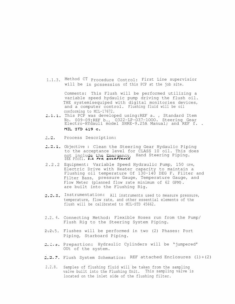
Method CT Procedure Control: First Line supervisiorwill be in pcssession of this PCP at the job site.
Comments: This Flush will be performed utilizing avariable speed hydaulic pump driving the flush oil.THE systemisequiped with digital monitories devices,and a computer control. Flushing fluid will be oilconforming to MIL-17672.This PCP was developed using:REF a. , Standard ItemNo. 009-09;REF b., O322-LP-O37-1OOO. Steering GearElectro-HYdauli model SHRE-9.25A Manual; and REF f. .
Process Description:
Objective : Clean the Steering Gear Hydaulic Pipingto the acceptance level for CLASS 10 oil. This doesnot include the Emergency, Hand Steering Piping.$EE Pfcfl.Equipment: Variable Speed Hydraulic Pump, 150 GPM,Electric Drive with Heater capacity to maintain aFlushing oil temperature Of 130-140 DEG F. Filter andFilter Bass, pressure Gauge, Temperature Gauge, andFlow Meter (planned flow rate minimum of 62 GPM).are built into the Flushing Rig.
Instrumentation: All instruments used to measure pressure,temperature, flow rate, and other essential elements of theflush will be calibrated to MIL-STD 45662.
Connecting Method: Flexible Hoses run from the Pump/Flush Rig to the Steering System Piping.
Flushes will be performed in two (2) Phases: PortPiping, Starboard Piping.
Prepartion: Hydraulic Cylinders will be “jumpered”OUt of the system.
Flush System Schematics: REF attached Enclosures (l)+(2)
Samples of flushing fluid will be taken from the samplingvalve built into the Flushing Unit. This sampling valve islocated on the inlet side of the flushing filter.

3. 1. Safety Precautions:
3.1.1. Flushing oil at 130-140 DEGS Fahrenheit can causeserious burns. Extreme caution will be exercised atall times. Danager signs will be posted Prior tostart of flush, and will remain posted throughout theflush.
3.1.2. Due to fire hazards, all hot work, welding, burn-ing, grinding, and smoking will be secured in thespace where the flush is being performed. NO HOTWORK and NO SMOKING signs will be posted at timesduring the flush.
3.2 Acceptance Standard
The fluid entering the temporary filter will meet the class10 requirements of NAS 1638 for particulate contamination.Water content shall not exceed 0.05 percent for any singlesample. The average of samples taken shall not exceed0.03 for the system.


S H I P : USS FOX (CG-33) ITEM NO: 561-11-001CHANGE ONE
Steering Gear: repair and test
1.2 Location of Work: Steering Gear Room (2-211-o-E)
1.3 Identification:
Qty (One) Steering Gear: Western Gear Corp., Mfr.ID SHRE9-25A. APL 600230013
Qty (Two) Main Pump: Vickers AOM Div. Sperry RandCorp. Mfr. ID PV2032. 9 Pistons, Type-Axialpiston, 1760 RPM, Mfr. Dw$ 824889. APL 019160309
Qty (Two) Replenishing Pump: Vickers AOM SparryRand Corp.. Mfr ID V200-8-1C12-5S8. 11.6 GPM.Type-RTY-Vane 12 Vanes, APL 019160319
Qty (Two) Motor: Reliance Electric Co. , Mfr. Dwg34926RevB. 60 HP. 440 VAC, 1760 RPM. APL 174751166
Qty (Two) Controller: Cutler-Hammer Inc.. Mfr ID6962ED681. Mfr Dwg 962-1-63M7. APL 151203022
a. Standard Itemsb. 0322-LP-037-1000,Electro-Hydraulic Steering Gear
Model SHRE-9.25Ac. 0936-LP-OO3-7O1O . Handbook of Cleaning Practicesd. MIL-STD-271e. 0900-LP-003-8000 . Surface Inspection Acceptance
Standards for. Metalsf. Mil-STD-419, Cleaning and Protecting Piping, Tubing
and fittings for Hydraulic Power TransmissionEquipment
g. 803-2145518, Spray Shields for Mechanical Joints
3.1 Accomplish the requirements of 009-23 of 2.a.
3.2 Remove. repair and test the units of 1.3 in accordancewith 3.3 through 3.21.3.
3.3 from the hydraulic steeringsystem.
CHANGE ONEPAGE 1 OF 7 ITEM NO: 561-11-001

sHI?: USS FOX (CG-33) ITEM No: 561’- 11-901
3.4.2 Clean each part free of foreign matter, using4 and 5 of 2.c. for guidance.
3.4.3 Inspect each part for wear and defects, using 2.5.guidance for accept or reject criteria.
3.4.3.1 Submit four legible copies of “a report
3.4.4 Accomplish liquid penetrant tests on each pumpvalve block and servo control
The accept or reject criteria
----
3.4.4.1 Submit four Legible copies of a report
3.5 Repair the port and starboard hydraulic pumps, connected
3.5.1 Stone the pump shaft seal areas and journals andremove high spots.
3.5.-2 Lap and polish the cylinder barrels, valve platesand replenishing valves.
3.5.3 Restore. mating surfaces-exposed-by disassemblyremoval . Repair by removing high spots. burrs, abrasions, andforeign matter, where removal can be accomplished by hand “tools.
3.5.3.1 Chase and tap exposed- threaded areas.
3.6 Reassemble the hydraulic pumps. connected relief valves,power limiter, servo control, replenishing valves and replenishingpumps , using 2.b. for guidance.
PAGE 2 OF 7CHANGE ONE
ITEM NO: 561-11-001

SHIP: USS FOX (CG-33) ITEM NO: 561-11-001CHANE ONE.
3.6.1 Remove existing and install new the followingparts:
Total Piece No.Quantity Name on 2 .5..Required of Part Fig. 2-2-11 Part No.
2 AY422422222222228
Sub-Assembly PistonBearingSealBearing. RearBearing, ThrustBearing, FrontRing. ThrustBearingSpringBearingBearing, CylinderBearingWasher.Thrust BearingRing, Thrust BearingSpringSeal
3314246474849525357626364656776
461568237417135812735744002133912133784439902948440063857119231420139620139720026142310
Seal Washer 6Sleeve 26Seal. Oil 47Spring 57Seal . Salt Water 70Seal 87
424242
B22311B22412.50005-sB10134124000550197-s
Piece No.on 2.b..Fig. 2-2-9
44
SpringBall
B-27661
Piece No.on 2.b.,Fig. 2-2-10
Bal1SpringSpringSeat,Valve
2222
3121514
A-101OO8A-331OO4A-331003A-441OO4
CHANGE ONEP A G E 3 0 F 7 ITEM NO: 561-11-001

S H I P : USS FOX (CG-33) ITEM NO: 56:-11-00:CHANGE ONE
3.6.2 Measure and record final sizes and clearances.using 2.5. for guidance.
3.6.2.1 SUbmit: four legible copies of a reportlisting results of the requirements of 3.6.2 to the SUPERVSOR.
3.7 Accomplish the requirements of 009-17 of 2.a. for theequipment listed in 1.3.4. using 2.b. . Chapter 3 for guidance.
3.7.1 Straighten each shaft to within 0.001 inch totalindicator reading.
3.3 Accomplish the requirements of 009-36 of 2.a. for eachcontroller listed in 1.3.5. using 2.b., Chapter 3 for guidance.
3.8.1 Submit four legible copies of a list of new partsinstalled in place of those found to be.missing and defective . withdocumenting invoices or other substantiating data. to theSUPERVISOR. Total cost of new Parts,identified to be replaced. shall not exced 450 dollars withoutprior approval of the SUPERVISOR. Total cost of new parts notspecifically identified to be replaced. greater or less than above
. dollar amount, will be the subject of an equitable adjustment.
5.9 Disassemble the port and starboard steering ram packingglands. using 2.b.. Figure 1-7-4 for guidance.
3.9.1 Measure and record sizes and clearances, using2.b., Figure 1-7-4 for guidance.
3.9.2 Clean each part free of foreign matter. usingChapter 4 and 5 of 2.C. for guidance.
3.lC Repair the port and starboard rams,-using 2.b. forguidance.
3.10.1 Hone each ram in way of packing gland to remove .glazing, scoring, and ridging.
3.11 Reassemble the port and starboardFigure 1-7-4 for guidance.
ram packing glands,
CHANGE ONEPAGE 4 OF 7 ITEM NO: 561-11-001

No: 561-11-001CHANGE ONE
3.11.: Remove existing and install newparts:
Total Piece No.Quantity Name . on 2.b.,Required of part Fig. 1-7-4
4 SE packing Assy. 134 Wiper Ring 178 Ram Soft Stop 20
the following
Mfr. Part N0.
N-1OO833FC13N-1OO833PC17c-l01437
3.11.1.1 Remove existing and install now capscsewsand washers. The material shall conform With the specifications onMaterial List of 2.b.. Figure 1-7-4.
3.12 Disassemble the helix screw assembly. using 2.b.. Figure1-7-7 for guidance.
3.12.1 Measure and record sizes and clearances. using2.b. , Figure 1-7-7 for guidance.
3.12.2 Clean each part free of foreign matter. usingChapter 4 and 5.of 2.b. for guidance.
3.13 Repair the helix screw assembly. using 2.b.. Figure 1-7-7for guidance.
3.13.1 Stone the helix screw to remove high spots.
3.14 “Reassemb1e the helix screw assembly. using 2.b., Figure1-7-7 for guidance.
3.15 Reinstall the port and starboard hydraulic pumps.including the connected relief valves, power limiter, servocontrol. replenishing valves and replenishing pumps. using 2.b. forguidance.
3.15.1 Remove existing and install new hold-down boltsand nuts conforming to-MIL-S-1222, Type III. Grado 5.
3.15.2 Align piping to each pump assembly, using 2.b. for guidance.
3.15.2.1 Remove existing and install- now pipingjoint o-rings. capscrews and washers. Material shall conform tothe specifications on the Material List of 2.b.. Figures 2-2-1 and2-2-2.
CHECK POINT (Alignment)
3.15.2 Align and couple the motor to the pump inaccordance with 2.b.
PAGE 5 0F 7 ITEM NO: 5S1-11-001

‘SHIP: USS FOX (CG-33) ITEM NO: 56l-11-oolCHANGE ONE
3.15.2.1 AlIgnment shall be accomplished withpiping installed. Piping. shall be supported independently of thepump and shall not impose a strain on the pump
3.15.3 Remove existing and install new coupling fasteners and seals, using 2.b. for guidance.
CHECK POINT (Flush)
3.16 Clean and flush the steering gear hydraulic system.
3.16.1 ACCOMPLISH THE REQUIREMENTS OF 009-09 0F 2.a. FOR FLUSHING THE HYDRAULICSYSTEM. THE PROCEDURE SHALL CONTAIN BUT NOT LIMITED TO THE FOLLOWING:
3.. 16.1.1 FILL THE STEERING GEAR SYSTEM WITH NEW OIL CONFORMING TO MIL-L-17672.
3.18.1.2 INSTALL JUMPER AND FLUSHING BLOCKS TO ACHIEVE A CONTINUOUS FLUSHTHROUGH THE SYSTEM IN ACCORDANCE WITH 2.F.
3. 16.1.3 MAINTAIN A FLUSHING OIL TEMPERATURE OF 130 TO 140 DEGREES
3. 16.1-.4 TAKE AND ANALYZE OIL SAMPLES IN ACCORDANCE WITH 2.f.
3.16.2 RESTORE THE SYSTEM TO FORMAL OPERATING STATUS ON COMPLETION OF FLUSH:
17672.
3.16.4
3.16.5 LUBRICATE THE STEERING GEAR IN ACCORDANCE WITH 2.B..FIGURE1-7-13.
3.16.6 REMOVE EXISTING AND INSTALLNEW HYDRAULIC SYSTEM FILTERS. MATERIAL SHALLCONFORM TO THE SPECIFICATIONS ON MATERIAL LIST OF 2.b.
3.17 Adjust and set steering system relief valves in.accordance with 2.b.
3.18 Install now aluminized cloth spray shields on hydraulicoil piping and valve flanges and Components in accordance with 2.g.
3.19 Accomplish the requirements of 009-32 of 2.a. for new anddisturbed surfaces.
3.20 The length of externally threaded fasteners shall be suchthat a minimum of two threads to a maximum of five threads shallprotrude beyond the crown of the tightened nut.
CHANGE ONEPAGE 6 OF 7 ITEM NO: 561-11-001

SHIP: USS FOX (CG-33) ITEM NO: 561-11-001CHANGE ONE
CHECK POINT (Operational Test)
3.21 Accomplish an operational test on the steering gearsyszem. using 2.b. for guidance.
3.21.1 Accomplish the requirementS of Work Item 841-11-001. using 2.b. for guidance.
3.21.2 Synchronize, adjust and set all steering angleindicators.
3.21.3 Submit four legible copies of a report listingresuits of the requirements of 3.21 to the SUPERVISOR.
4. NOTES :
4.1 This is an LOE item.
5. GOVERNMENT FURNISHED MATERIAL(GEM)
5.1 None.
CHANGE ONEITEM NO: 561-11-001


L A B O R A T O R Y R E P O R T
Telephone (619) 425-1993 Established
CLARKSON LABORATORY A N D S U P P L Y INC.350 Trousdale Dr. Chula Vista, Ca. 92010A N A L Y T I C A L A N D C O N S U L T I N G C H E M I S T S
Date: 08-30-90Purchase Order Number: NH160525Account Code : NAT
To:* *
NATIONAL STEEL & SHIPBUILDING CO.P. O. BOX 85278SAN DIEGO, CA 92138Mail stop #15Attention: Jim Fellerman
Laboratory Number: PC-2560 Customer Phone Number: 544-7748
Sample Designation:* *
One oil sample dated on 08-28-90, from USS FOXCG-33 3328-85 245, marked as STBD Unit 0700 132, #l.
ANALYSIS:
Particle Sizein Microns
5 - 15
15 - 25
25 - 50
50 - 100
over 100
Water by Karl FisherASTM D-1744
Notes: ThisK =
sample meets class 61000
Number of Particles per 100ml.
NAS 1638 Class 6Sample Specifications
2250 16 K
710 2850
139 5 0 6
14 90
14 16
0.03 %
NAS 1638.
APO/mv
L A B O R A T O R Y R E P O R T
Telephone (619) 425-1993
C L A R K S O N L A B O R A T O R Y A N D S U P P L Y
350 Trousdale Dr. Chula Visa, Ca. 92010A N A L Y T I C A L A N D C O N S U L T I N G C H E M I
Date: 08-30-90purchase Order Number: NH160525Account Code : NAT
To:
NATIONAL STEEL & SHIPBUILDING CO.P. O. BOX 85278SAN DIEGO CA 92138Nail stop #15Attention: Jim Fellermam
Laboratory Number: PC-2561 Customer Phone Number:
Sample Designation:* *
One oil sample dted on 08-28-90,CG-33 3328-85 245, marked as STBD
from USS FOXUnit 1100 138, #2.
ANALYSIS:
particle Sizein Microns
5 - 15
15 - 25
25 - 50
50 - 100
Over 100
Water by Karl FisherASIM4 D-1744
Notes: ThisK =
sample neets class1000
Established 1928
INC.
S T S
544-7748
6
Number of Particles per 100ml.* *
NAS 1638 Class 6 Sample specifications
1814 16 K
282 2850
60 506
12 90
14 16
0.04 %
NAS 1638.
A1ma Patricia Ortega
APO/mv
L A B O R A T O R Y
Telephone (619) 425-1993 Established 1928
C L A R K S O N L A B O R A T O R Y A N D S U P P L Y I N C .350 Trousdale Dr. Chula Vista, Ca. 92010A -NALYTICAL AND CONSULTING C H E M I S T S
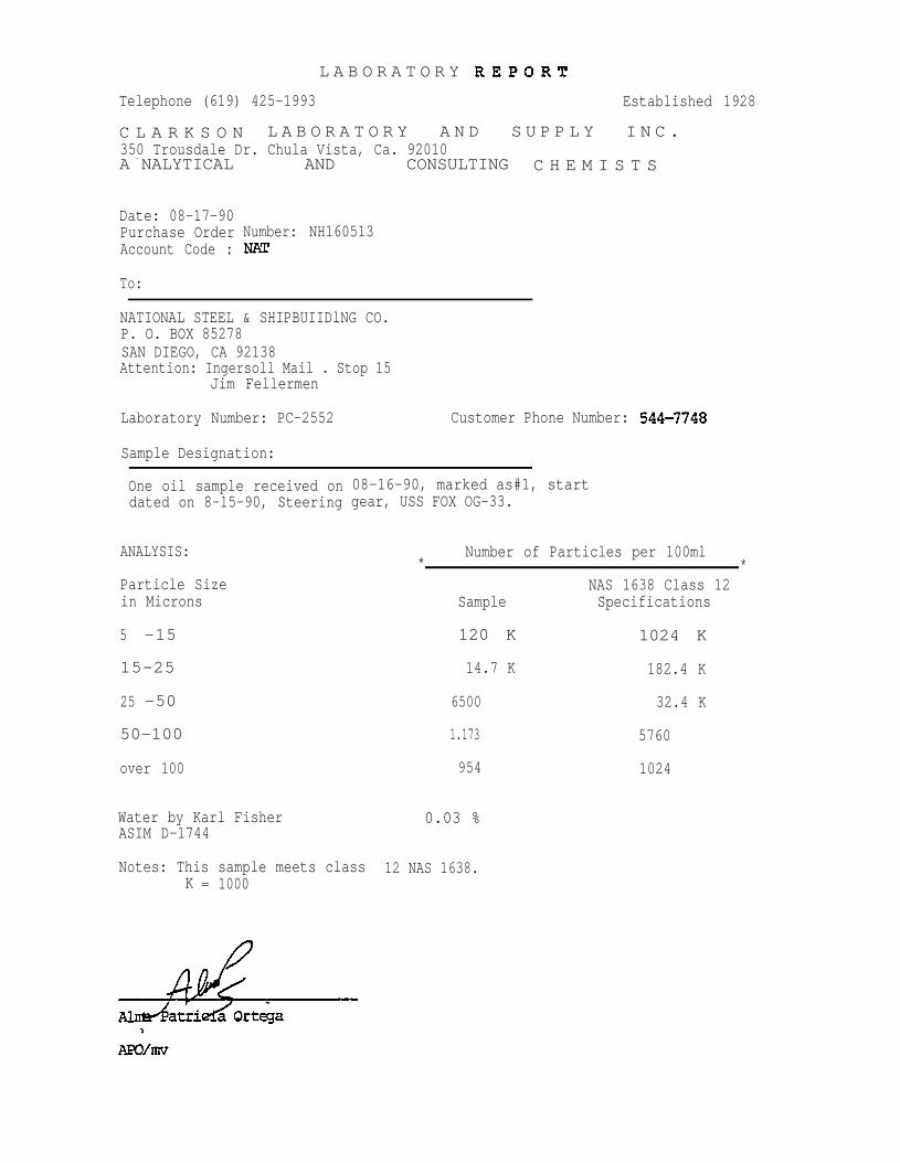
Date: 08-17-90Purchase OrderAccount Code :
Number: NH160513
To:
NATIONAL STEEL & SHIPBUIIDlNG CO.P. O. BOX 85278SAN DIEGO, CA 92138Attention: Ingersoll Mail . Stop 15
Jim Fellermen
Laboratory Number: PC-2552 Customer Phone Number:
Sample Designation:
One oil sample received ondated on 8-15-90, Steering
08-16-90, marked as#1, startgear, USS FOX OG-33.
Number of Particles per 100ml* *
NAS 1638 Class 12Sample Specifications
ANALYSIS:
Particle Sizein Microns
120 K 1024 K5 -15
15-25 14.7 K 182.4 K
25 -50 6500 32.4 K
50-100 1.173 5760
954 1024over 100
Water by Karl FisherASIM D-1744
0.03 %
Notes: This sample meets classK = 1000
12 NAS 1638.

Telephone (619) 425-1993Established
C L A R K S O N L A B O R A T O R Y A N D s U P P L Y INC.
350 Trousdale Dr. Chula Vista, Ca. 92010A N A L Y T I C A L A N D C O N S U L T I N G C H E M I S T S
Date: 08-17-90Purchase Order Number: NHI60513Account Cede : NAT
To:* *
NATIONAL STEEL & SHIPBUILDING CO.P. O. BOX 85278.SAN DIEGO CA 92138Attention: Ingersoll Mail Stop 15
Jim Felleemen
Laboratory Number: PC-2553 Customer Phone Number: 544-7748
Sample Designation: *
One oil sample received on 08-16-90, marked as #2, 30minutes, dated on 8-15-90, Steering Gear USS FOX OG-33.
ANALYSIS:
particle Sizein Microns
5 -15
15-25
25 -50
50 -100
over 100
Water by Karl FisherASM D-1744
Notes: This sample meets class 6K = 1000
Number of Particles per 100ml
Sample
12.3 K
292
78
14
10
0.04 %
NAS 1638.
NAS 1638 Class 6Specifications
16 K
2850
506
90
16
APO/mv
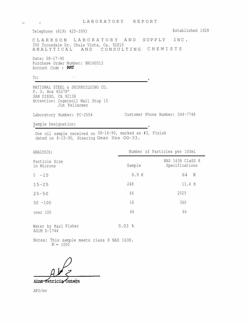
.,. . L A B O R A T O R Y R E P O R T
Telephone (619) 425-3993 Established 1928
C L A R K S O N L A B O R A T O R Y A N D S U P P L Y I N C .350 Trousdale Dr. Chula Vista, Ca. 92010A N A L Y T I C A L A N D C O N S U L T I N G C H E M I S T S
Date: 08-17-90Purchase OrderAccount Code :
To:
Number: NH160513
.*
NATIONAL STEEL & SHIPBUILDING CO.P. O. Box 85278”SAN DIEGO, CA 92138Attention: Ingersoll Mail Stop 15
Jim Fellermen
Laboratory Number: PC-2554 Customer Phone Number: 544-7748
Sample Designation:* *
One oil sample received ondated on 8-15-90, Steering
ANALYSIS:
Particle Sizein Microns
5 -15
15-25
25-50
50 -100
over 100
Water by KarlASlM D-1744
Fisher
08-16-90, marked as #3, FinishGear Uss OG-33.
Number of Particles per 100ml
NAS 1638 ClaSS 8Sample Specifications
8.9 K 64 K
248 1I.4 K
66 2025
18 360
64 64
0.03 %
Notes: This sample meets class 8 NAS 1638.K = 1000
APO/mv
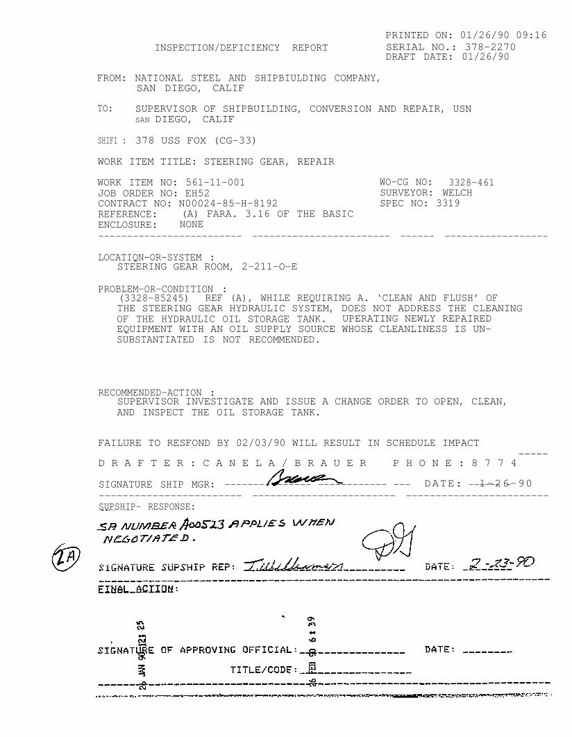
PRINTED ON: 01/26/90 09:16INSPECTION/DEFICIENCY REPORT SERIAL NO.: 378-2270
DRAFT DATE: 01/26/90
FROM: NATIONAL STEEL AND SHIPBIULDING COMPANY, SAN DIEGO, CALIF
TO: SUPERVISOR OF SHIPBUILDING, CONVERSION AND REPAIR, USNSAN DIEGO, CALIF
SHIFI : 378 USS FOX (CG-33)
WORK ITEM TITLE: STEERING GEAR, REPAIR
WORK ITEM NO: 561-11-001 WO-CG NO: 3328-461JOB ORDER NO: EH52 SURVEYOR: WELCHCONTRACT NO: N00024-85-H-8192 SPEC NO: 3319REFERENCE: (A) FARA. 3.16 OF THE BASICENCLOSURE: NONE------------------------- ------------------------ ------ ------------------
LOCATIQN-OR-SYSTEM :STEERING GEAR ROOM, 2-211-O-E
PROBLEM-OR-CONDITION :(3328-85245) REF (A), WHILE REQUIRING A. ‘CLEAN AND FLUSH’ OFTHE STEERING GEAR HYDRAULIC SYSTEM, DOES NOT ADDRESS THE CLEANINGOF THE HYDRAULIC OIL STORAGE TANK. UPERATING NEWLY REPAIREDEQUIPMENT WITH AN OIL SUPPLY SOURCE WHOSE CLEANLINESS IS UN-SUBSTANTIATED IS NOT RECOMMENDED.
RECOMMENDED-ACTION :SUPERVISOR INVESTIGATE AND ISSUE A CHANGE ORDER TO OPEN, CLEAN,AND INSPECT THE OIL STORAGE TANK.
FAILURE TO RESFOND BY 02/03/90 WILL RESULT IN SCHEDULE IMPACT
D R A F T E R : C A N E L A / B R A U E R P H O N E : 8 7 7 4-----
SIGNATURE SHIP MGR: -------- ------ ------------ --- DATE: l-26-90------ ------------------------- ------------------------ ------------------------SUPSHIP- RESPONSE:

PRINTED ON: 01/18/9O 07:59INSPECTION/DEFICIENCY REPORT SERIAL NO.: 378-02052
DRAFT DATE: 01/18/90
FROM:. NATIONAL STEEL AND SHIPBUILDING COMPANY, . ,
TO:
SHIP:
SAN DIELU CALIT
SUPERVISOR OF SHIPBUILDING, CONVERSION AND REPAIR, USNSAN DIEGO, CALIF
378 USS FOX (CG-33)
WORK ITEM TITLE: STEERING GEAR; REPAIR AND TEST
WORK ITEM NO: 561-11-001 WO-CG NO: 3328-461JOB ORDER NO: EH52 SURVEYOR: WILLIAMSONCONTRACT NO: NOO024-85-H-8192 SPEC NO: 3319REFERENCE: (A) FARAS. 3.16.1.1 AND 3.16.3ENCLOSURE: NONE
LOCATION-OR-SYSTEM :STEERING GEAR ROOM 2-211-O-E
PROBLEM OR CONDITION:(3328-85245) MIL-L-17672 IS SPECIFIED IN THE WORK ITEM.CONTRACTOR RELIEVES THIS TO BE IN ERROR AND SHOULD BEMIL-H-17672. WHICH COVERS THREE TYPES OF OIL.
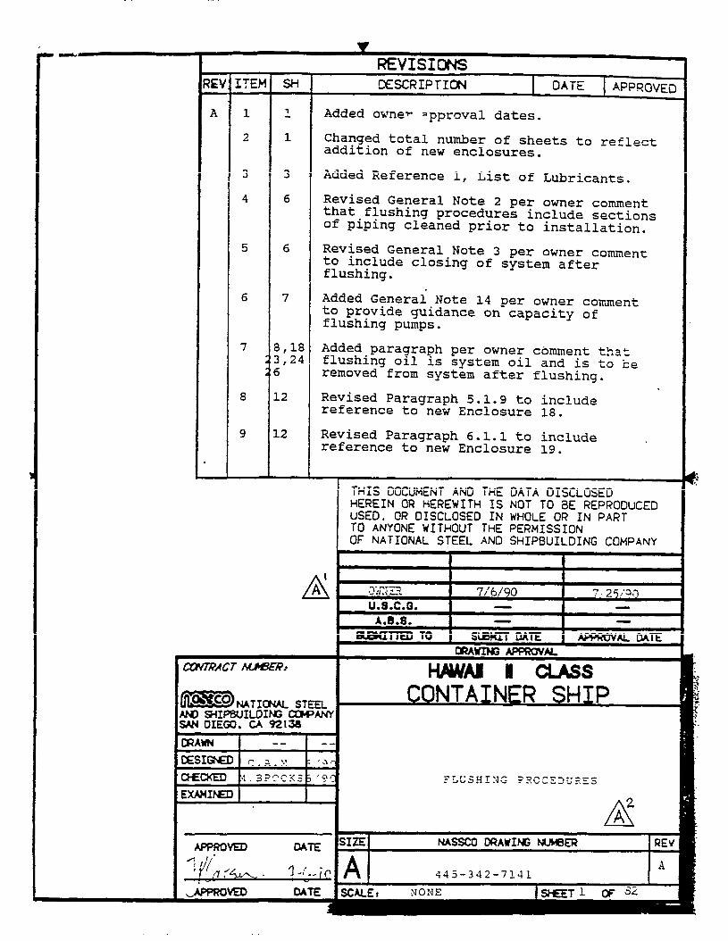


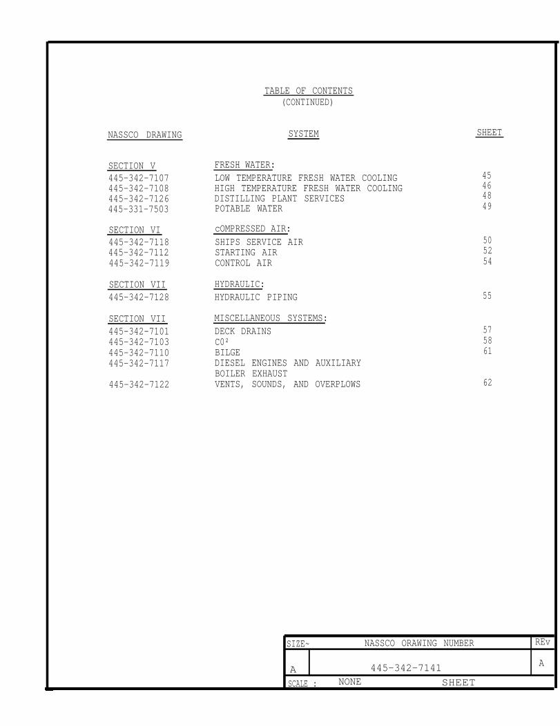
NASSCO DRAWING
SECTION V445-342-7107445-342-7108445-342-7126445-331-7503
SECTION VI445-342-7118445-342-7112445-342-7119
SECTION VII445-342-7128
SECTION VII445-342-7101445-342-7103445-342-7110445-342-7117
445-342-7122
TABLE OF CONTENTS(CONTINUED)
SYSTEM
FRESH WATER:LOW TEMPERATURE FRESH WATER COOLINGHIGH TEMPERATURE FRESH WATER COOLINGDISTILLING PLANT SERVICESPOTABLE WATER
cOMPRESSED AIR:SHIPS SERVICE AIRSTARTING AIRCONTROL AIR
HYDRAULIC:HYDRAULIC PIPING
MISCELLANEOUS SYSTEMS:DECK DRAINSC0²BILGEDIESEL ENGINES AND AUXILIARYBOILER EXHAUSTVENTS, SOUNDS, AND OVERPLOWS
SHEET
45464849
505254
55
575861
62
SIZE~ NASSCO ORAWING NUMBER REv
A 445-342-7141 A
SCALE : NONE SHEET

1.
4.
5.
6.
7.
8.
GENERAL NOTES
Piping systems will be cleaned, flushed, and maintained to theextent necessary to ensure satisfactory operation of the systemand components in service.
Piping sections fabricated in the shop may be flushed in theshop prior to shipboard installation. Sections of piping, suchas gage lines or dead legs, may be cleaned by hand in the shop oronboard ship. Sections of piping satisfactorily cleaned in theshop or by hand will be included in system flushing as providedfor in the flushing procedures. Individual cleaning of pipingsections such as gage lines and dead legs is acceptable if theyuse mechanical joints.
Maintain cleanliness of piping and components by sealing openingswhen joints and fittings are disconnected for flushing pump, temp-orary strainer, spool piece, or jumper installation. After com-pletion of flushing, piping systems and tanks should be closed as soon as practicable to prevent entry of foreign matter.
Any temporary fittings such as jumpers, blanks, and spool piecesmust be cleaned, flushed, and degreased prior to installation.
Prior to flushing, units having in line mechanisms capable oftrapping or affected by carry over of foreign matter will eitherbe removed or blanked off and bypassed. These items will be in-spected for cleanliness prior to a system startup. This appliesprimarily to pipe spuds on tanks or other system components notused and dead legs.
Refer to system diagrams when conducting the flushing proceduresfor installation of jumpers, spool pieces, flushing pumps, andstrainers. Valve line ups will be conducted using the systemdiagrams.
Check for system leakage when filling system and when temporaryor installed pumps are operated.
Vibration of systems during flushing will be required on specificsystems as noted in the flushing procedure. Other systems maybe vibrated as necessary.
SIZE NASSCO DRAWING NUMBER REV
A l 445-342-7141 A
SHEET 6

9.
10.
11.
12.
13.
Air for piping blowdown will be dry and oil-free.
Tanks and sumps are required to be open for some flushing paths.Where these procedures indicate hose jumpers are used to bypasstanks or sumps, as an alternative the tank or sump may be usedin the flow path. Conversely, where the tank is used in the flush-ing path, it may be bypassed using hose jumpers.
Temporary or installed strainers or filters should be closelymonitored and cleaned when gages indicate strainer or filter isclogged. Most large particles of rust and foreign matter willbe collected in the first few hours of flushing. It may be neces-sary to clean strainers or filters and change installed muslinbags every 15 minutes.
These procedures provide methods to flush the entire system ormajor sections of the systems. The systems may be flushed insmaller segments using the procedures for the entire system ormajor section.
Temporary strainers used for flushing shall be capable of havingmuslin bags installed. Temporary strainers shall also have mag-nets installed.
Temporary flushing pumps must be of sufficient capacity to developline velocities which will transport debris, etc. from the system.
SIZE NASSCO DRAWING NUMBER REV
A 445-342-7141 A
SCALE NONE SHEET 7
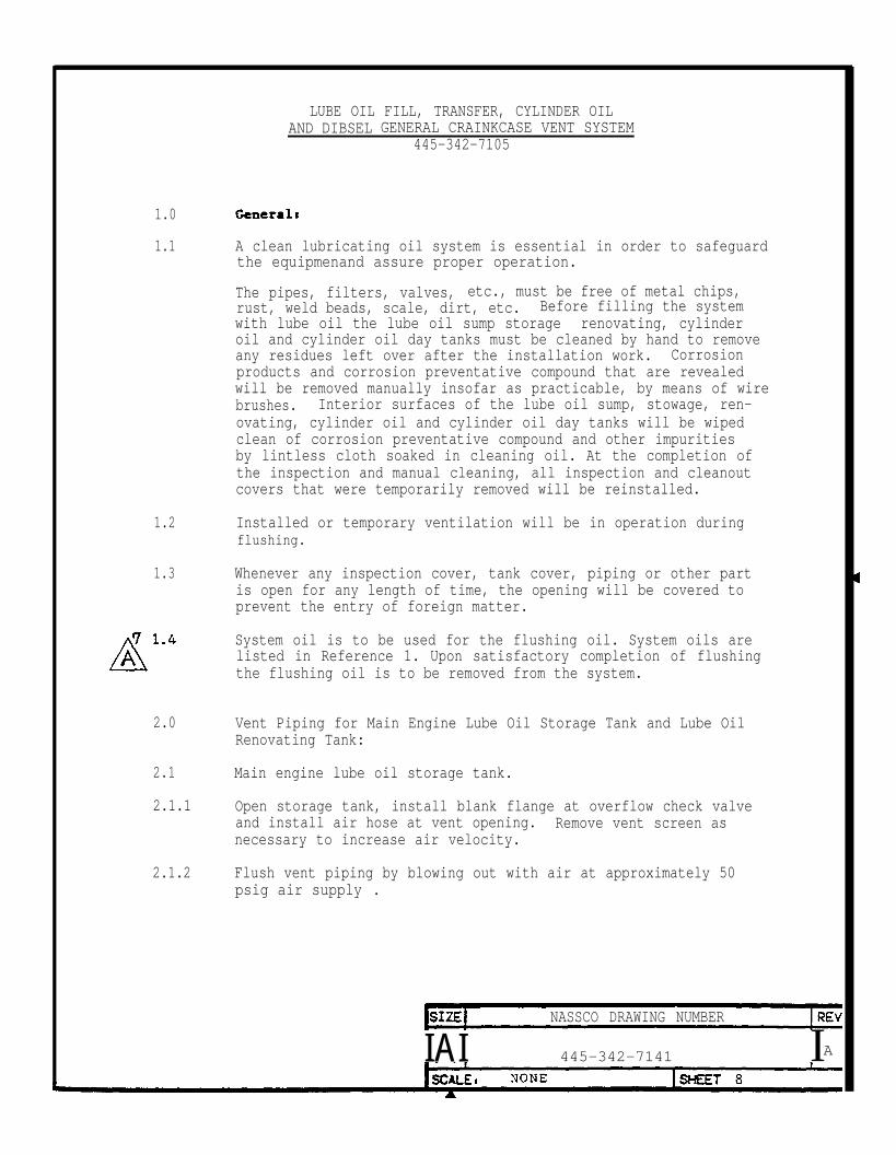
1.0
1.1
1.2
1.3
LUBE OIL FILL, TRANSFER, CYLINDER OILAND DIBSEL GENERAL CRAINKCASE VENT SYSTEM
445-342-7105
A clean lubricating oil system is essential in order to safeguardthe equipmenand assure proper operation.
The pipes, filters, valves, etc., must be free of metal chips,rust, weld beads, scale, dirt, etc. Before filling the systemwith lube oil the lube oil sump storage renovating, cylinderoil and cylinder oil day tanks must be cleaned by hand to removeany residues left over after the installation work. Corrosionproducts and corrosion preventative compound that are revealedwill be removed manually insofar as practicable, by means of wirebrushes. Interior surfaces of the lube oil sump, stowage, ren-ovating, cylinder oil and cylinder oil day tanks will be wipedclean of corrosion preventative compound and other impuritiesby lintless cloth soaked in cleaning oil. At the completion ofthe inspection and manual cleaning, all inspection and cleanoutcovers that were temporarily removed will be reinstalled.
Installed or temporary ventilation will be in operation duringflushing.
Whenever any inspection cover, tank cover, piping or other partis open for any length of time, the opening will be covered toprevent the entry of foreign matter.
System oil is to be used for the flushing oil. System oils arelisted in Reference 1. Upon satisfactory completion of flushingthe flushing oil is to be removed from the system.
2.0 Vent Piping for Main Engine Lube Oil Storage Tank and Lube OilRenovating Tank:
2.1 Main engine lube oil storage tank.
2.1.1 Open storage tank, install blank flange at overflow check valveand install air hose at vent opening. Remove vent screen asnecessary to increase air velocity.
2.1.2 Flush vent piping by blowing out with air at approximately 50psig air supply .
NASSCO DRAWING NUMBER
IAI 445-342-7141 IA

2.1.3 During blowout, periodically vibrate the system piping withvibrators, wooden mallets or other equivalent means.
2.1.4 Continue blowout until discharge into tank is visually free offoreign matter.
2.1.5 After completion of blowout, remove air hose. Reconnect pipingas necessary.
2.2 Lube Oil Renovating Tank:
2.2.1 Blow-out vent piping as described in paragraph 2.1.
2.3 Lnbe Oil Purifer Sludge Tanks:
2.3.1 Blow-out vent piping as described in paragraph 2.1.
3.0 Vent and Overflow Piping for Diesel Generator Lube Oil StorageTank, Cylinder Oil Storage Tanks and Cylinder Oil Day Tank
3.1 Diesel generator lube oil storage tank
3.1.1 Open diesel generator lube oil storage tank and lube oil purifiersludge tank. install blank at overflow piping and install air hoseat vent opening. Remove vent screen as necessary toincrease air velocity.
3.1.2 Flush vent piping by blowing out with air at approximately 50 paig.
3.1.3 During blowout, periodically vibrate the system with vibrators,wooden mallets or other equivalent means.
3.1.4 Continue blowout until discharge into tank is visually free offoreign matter.
3.1.5 Remove blank at overflow piping, reconnect piping and blankvent/overflow piping to tank.
3.1.6 Flush overflow piping to sludge tank by blowing out with air atapproximately 50 paig.
SIZE NASSCO DRAWING NUMBER REV
A 445-342-7141 A
SCALE: NONE SHEET 9

3.1.7 Continue blow out Until discharge into sludge tank is visually freeof foreign matter.
3.1.8 After completion of blowout, remove air hose. Restore system pipingas necessary.
3.2 Cylinder Oil Storage Tanks:
3.2.1 Blow-out vent and overflow piping to lube oil purifier sludgetank as described in paragraph 3.1. Blow-out vents and overflowsfor both storage tanks.
3.3. Cylinder Oil Day Tank:
3.3.1 Blow-out vent and overflow piping as described in paragraph 3.1except discharge is to cylinder oil tank.
4.0
4.1
4.1.1
4.1.2
4.1.3
4.1.4
4.1.5
4.1.6
4.1.7
Deck Filling piping TO Lube Oil Tanks:
Main engine lube oil storage tank.
Open storage tank and install temporary flushing pump, duplexstrainer, heater, hose jumpers and blanks as shown in Enclosure1. Flushing path will be from deck fill connection to storage tank.
Install muslin bags in the temporary duplex strainer. Fillthe piping system with clean lube oil through the temporarystrainer.
Heat the lube oil to 160°-170ºF and circulate the heated oilthrough the system piping.
During circulation, periodically vibrate the system pipingwith vibrators, wooden mallets or other equivalent means.
Inspect strainers and muslin bags and clean as necessary.Replace muslin bags when they become coated with foreignmatter.
Continue flushing until the muslin bags remain visually freeof foreign matter.
Shift flushing unit outlet to the other deck fill connectionand repeat flush.
ASIZE NASSCO DORAWING NUMBER REV
A 445-342-7141 A
SCALE 1 NONE SHEET 10

4.1.8 After flushing of both deck fill paths is complete, removetemporary flushing equipment and restore system as necessary.
4.2 Diesel Generator Lube Oil Storage Tank:
4.2.1 Flush deck fill piping as described in paragraph 4.1 using dieselgenerator lube oil.
4.3 Cylinder Oil Tanks:
4.3.1 Flush deck fill piping as described in paragraph 4.1 using theinitial flushing path for one tank as shown in Enclosure 2. Usecylinder oil. When initial flushing path is clean, operate valvesto other tank fill connection to flush piping between tanks.
4.3.2 Shift flushing unit outlet to other deck fill connection and repeatflush.
4.3.3 After flushing is complete remove temporary flushing equipmentand restore system as necessary.
5.0 Overflow And Sump Fill Piping For Lube Oil Tanks:
5.1 Main engine lube oil storage tank and renovating tank overflowand sump fill.
5.1.1 Open storage tank and lube oil sump and install temporary flush-ing pump, duplex strainer, heater, hose jumpers and blank flangesas shown in Enclosure 3. Flushing path will be from main enginelube oil sump fill line to overflow line.
5.1.2 Install muslin bags in the temporary duplex strainers for theflushing pump strainer. Fill the piping system with clean lubeoil through the temporary strainer.
5.1.3 Heat the lube oil to 160° - 170° F and circulate the heated oilthrough the system piping.
5.1.4 During circulation periodically vibrate the system piping withvibrators, wooden mallets or other equivalent means.
5.1.5 inspect temporary strainer and muslin bag and clean as necessary.Replace mus1in bags when they become coated with foreign matter.

5.1.6 Continue flushing until the muslin bags remain visually free of foreign matter.
5.1.7 Upon completion of flushing, shift discharge of temporary flushingunit to lube oil sump suction bellmouth. Install hose jumper inrenovating tank between overflow line and suction piping as shownin Enclosure 4. Install blank flanges in vent piping or vent.
5.1.8 Repeat procedure of paragraph 5.1.2 through 5.1.6 to flush lubeoil renovating tank overflow piping.
After flushing of overflow piping is complete shift hose jumperfor renovating tank to connect inlet from lube oil transferpump/purifier discharge to tank outlet as shown in Enclosure 18.Shift temporary flushing pump and strainer to bypass lube oil trans-fer pump. Remove lube oil transfer pump suction strainer and installspool piece.
5.1.10 Line up lube oil transfer pump piping to renovating tank to flushfrom renovating tank through temporary flushing pump to dischargeto renovating tank. Fill system with lube oil, heat lube oil to160° - 170° F and circulate the heated oil through the system piping.
5.1.11 During circulation periodically vibrate the system piping withvibrators, wooden mallets or other equivalent means.
5.1.12 Continue flushing until the muslin bags are visually free offoreign matter.
5.1.13 Upon completion of flushing remove temporary flushing unit andrestore system as necessary. Clean and reinstall transfer pumpsuction strainer. Hose jumper for renovating tank should remainin place for flushing of purifier piping.
6.0 Main Engine Lube Oil Purifier Piping:
6.1 Renovating Tank.
Install temporary flushing pump and strainer at main engine lubeoil purifier supply and return piping connections to flush purifierpiping for renovating tank and piston rod stuffing box tank as shownin Enclosure 19.
6.1.2 Line up system to flush renovating tank purifier supply and returnpiping using hose jumper installed in paragraph 5.1.9. Fill systemwith lube oil and heat to 160° - 170° F and circulate the heatedoil through the system piping.
SIZE NASSCO DRAWING NUMBER REv
A 445-342-7141 A
SCALE : NONE SHEET 12

6 . 1 . 3
6 . 1 . 4
6 . 1 . 5
6 . 2
6 . 2 . 1
6.2.2
6.2.3
6.2.4
6.2.5
During circulation periodically vibrate the system piping withvibrators, wooden mallets or other equivalent means.
Continue flushing until muslin bags are visually free of foreignmatter.
Upon completion of flushing, remove hose jumpers from renovatingtank. If no further flushing or testing is to be conducted thatrequires tank to be open, clean tank and install cover.
Piston Bod stuffing Box Tank:
With temporary flushing pump, strainer and heater installed atmain engine lube oil purifier connections,line system up to flushsupply and return piping for piston rod stuffing box drain oil fil-tration unit. Install hose jumper to connect supply and returnpiping at piston rod stuffing box tank.
Fill system with lube oil, heat to 160° - 170° F and circulate theheated oil through the system piping.
During circulation periodically vibrate the system piping withvibrators, wooden mallets or other equivalent means.
Continue flushing until muslin bags are visually free of foreignmatter.
Upon completion of flushing, remove temporary flushing equipmentand hose jumpers. Restore System as necessary.
7.0 Diesel Generator Lube Oil Pipings
7.1 Diesel generator lube oil sump fill.
7.1.1 Open diesel generator lube oil storage tank and install temporaryflushing pump, strainer, heater, hose jumpers and blank flangesas shown in Enclosure 5.
7 . 1 . 2 Install muslin bags in the temporary strainers. Fill the flushingpiping system with diesel generator lube oil through the temporarystrainer.
7.1.3 Heat the diesel generator lube oil to 160° - 170° F and circulatethe heated oil through the system piping.
NASSCO DRAWING NUMBER
A 445-342-7141 A
SCALE: NONE SHEET 13A

7.1.4 During circulation periodically vibrate the system piping withvibrators, wooden mallets or other equivalent means.
7.1.5 Inspect atrainers and muslin bags and clean as necessary.Replace muslin bags when they become coated with foreign matter.
7.1.6 Continue flushing until the muslin bags remain visually free offoreign matter.
7.1.7 Shift flushing path to another diesel generator and repeat the flush.After the second diesel generator piping is flushed, shift the flush-ing path to the third diesel generator and repeat the flush.
7.1.8 Upon completion of flushing remove temporary flushing equipmentand restore system as necessary. If no further flushing ortesting is to be conducted that requires the storage tank to beopen, clean tank and install cover.
7.2 Diesel Generator Lube Oil Sump Purification Piping:
7.2.1 Install temporary flushing pump, strainer, heater, hose jumpersand blank flange to flush diesel generator lube oil sump purifi-cation piping. Install pump, strainer and heater at purifierpiping connections for diesel generator lube oil. Install hosejumpers to bypass each diesel generator lube oil Bump.
7.2.2 Line up system to flush one diesel generator’s lube oil purificationpiping. Fill system with diesel generator lube oil, heat to 160°- 170°F and circulate heated oil through the system piping.
7.2.3 During circulation periodically vibrate the system piping with vi-brators, wooden mallets or other equivalent means.
7.2.4 Continue flush until muslin bags are visibly free of foreign mat-ter.
7.2.5 Shift flushing path to another diesel generator and repeat the flush.
7.2.6 After the second diesel generator lube oil lines are clean, shiftthe flushing path to the third diesel generator and repeat the flush.
7.2.7 After flushing of all diesel generators purification piping iscomplete, remove temporary flushing equipment and restore systemas necessary.
8.0 Diesel Generator Lube Oil Sump Vents:
8.1 Disconnect vent piping at diesel generator lube oil sump. Installair hose at vent opening on weather deck. Remove vent screen asnecessary to increase air velocity.
SIZE NASSCO DRAWING NUMBER REV
A 445-342-7141 A
SCALE : NONE SHEET 14A

8.2
8.3
8.4
9.0
9.1
9.2
9.3
9.4
9.5
9.6
Flush vent piping by blowing out with air at approximately 50psig supply pressure.
Continue blowout until discharge is visually free of foreignmatter.
Upon completion of blowout, remove air hose, restore system asnecessary.
Cylinder Oil Transfer Piping:
Open one cylinder oil tank and install temporary flushing pump,strainer, heater, hose jumpers and blank flanges as shown in Enc-losure 6. install hose jumpers to bypass cylinder oil transferpumps and a spool piece to replace installed strainer.
Install muslin bags in the temporary strainer, fill the systemwith cylinder oil, heat the oil to 160° - 170° F and circulatethe heated oil through the system.
Flushing path will be from cylinder oil tank, bypasai ng one pump,through cylinder oil day tank, gravity fill to main engine cylinderlube oil connection and returning to the cylinder oil tank.
During circulation periodically vibrate the system piping withvibrators, wooden mallets or other equivalent means.
When muslin bags remain visually free of foreign matter, shiftflow path to the other transfer pump piping and to the othercylinder oil tank by shifting the temporary flushing pump dischargefrom one cylinder oil tank to the other, continueflushing until muslin bags remain visibly free of foreignmatter.
After flushing is complete, remove temporary flushing equipmentand restore system as necessary. Clean and reinstall strainer.If no further flushing or testing is to be conducted that requirestanks to be open, clean tanks and install covers.
10.0 Lube oil Purifier Drainst
10.1 Open lube oil sludge tank. Blowout lube oil purifier drains tosludge tank prior to connecting drains to purifier.
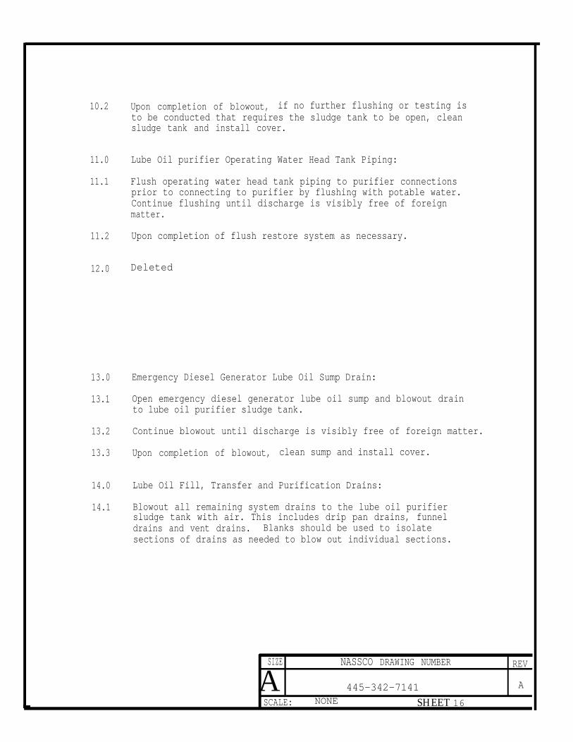
10.2 Upon completion of blowout, if no further flushing or testing isto be conducted that requires the sludge tank to be open, cleansludge tank and install cover.
11.0 Lube Oil purifier Operating Water Head Tank Piping:
11.1 Flush operating water head tank piping to purifier connectionsprior to connecting to purifier by flushing with potable water.Continue flushing until discharge is visibly free of foreignmatter.
11.2 Upon completion of flush restore system as necessary.
12.0 Deleted
13.0 Emergency Diesel Generator Lube Oil Sump Drain:
13.1 Open emergency diesel generator lube oil sump and blowout drainto lube oil purifier sludge tank.
13.2 Continue blowout until discharge is visibly free of foreign matter.
13.3 Upon completion of blowout, clean sump and install cover.
14.0 Lube Oil Fill, Transfer and Purification Drains:
14.1 Blowout all remaining system drains to the lube oil purifiersludge tank with air. This includes drip pan drains, funneldrains and vent drains. Blanks should be used to isolatesections of drains as needed to blow out individual sections.
SIZE NASSCO DRAWING NUMBER REV
A 445-342-7141 A
SCALE: NONE SHEET 16
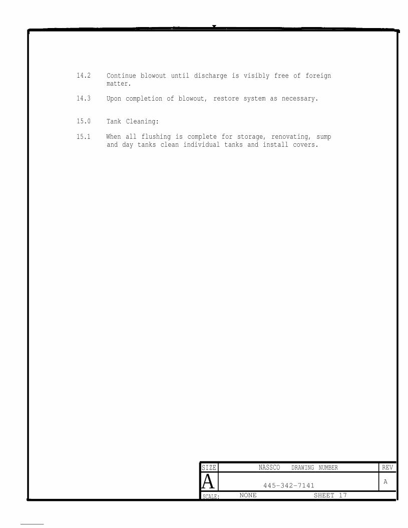
14.2 Continue blowout until discharge is visibly free of foreignmatter.
14.3 Upon completion of blowout, restore system as necessary.
15.0 Tank Cleaning:
15.1 When all flushing is complete for storage, renovating, sumpand day tanks clean individual tanks and install covers.
SIZE NASSCO DRAWING NUMBER REV
A 445-342-7141A
SCALE: NONE SHEET 17
LUBE OIL SERVICE SYSTEM445-342-7106
1.0 General
1.1 Lube oil piping will be pickled. Prior to pickling the interiorsurfaces of piping and fittings will be wire brushed to the maximumextent possible and blown out with air to remove loose particles.After pickling piping and fittings will be sealed at the open ends.Valves will be blown clean with steam or air to remove loose scale,sand and welding beads. Open ends will be sealed after cleaning.
1.2 A clean lubricating oil system is essential in order to safeguardthe equipment and assure proper operation.
The piping, coolers, filter’s, Valves, etc., must be free of metalchips, rust, weld beads, scale, dirt, etc. Before filling the sys-tem with lube oil, the crankcase and lube oil sump, must becleaned by hand to remove any residues left over after the instal-lation work. Corrosion products and corrosion preventative compound that are revealed will be removed manually in-so-far as practicable,by means of wire brushes. Interior surfaces of the lube oil sump,and crankcase will be wiped clean of corrosion preventative com-pound and other impurities by lintless cloth soaked in cleaningoil. Care should be taken to ensure that the self-cleaning straineris clean. At completion of inspection and manual cleaning, allinspection and cleanout covers that were temporarily removed willbe reinstalled.
1.3 The main engine lube oil purification system will be installed,flushed and ready for operation.
Main engine lube oil pumps will be used to circulate lube oilduring flushing. Muslin bags will be installed in pump suctionstrainers. Pump suctions will be checked for cleanliness priorto final installation. Lube oil suction bellmouths and lube oilsump tank will be checked for cleanliness prior to filling thesump with lube oil.
1.5 Installed or temporary ventilation will be in operation duringflushing.
1.6 Whenever any inspection cover, tank cover, piping or other partis open for any length of time, the opening will be covered toprevent the entry of foreign matters.
System oil is to be used for the flushing oil. System oils arelisted in Reference 1. Upon satisfactory completion of flushingthe flushing oil is to be removed from the system.
SIZE NASSCO DRAWING NUMBER REV
A 445-342-7141 A
SCALE: NONE SHEET 18
2.0 Main Engine Lube Oil Service System
2.1 The initial flushing of the main engine lube oil system will bypassthe main lube oil cooler, self-cleaning strainer and main engine.Temporary strainers will be installed to remove foreign matter fromthe system.
2.2 Self-Cleaning Strainer Backflush Drain Line and Lnbe Oil Outletfrom Turbo Charger
2.2.1 Install a temporary flushing pump, strainer, heater and hosejumpers to flush the self-cleaning strainer backflush drain lineand main engine lube oil outlet from turbocharger piping. Temp-orary strainers will be installed at the lube oil sump.
Install muslin bags in temporary strainers. Fill piping with lubeoil, heat to 120°-130° F and circulate heated oil through piping.Continue flush until muslin bags are visibly free of foreign matter.
2.2.3 Upon completion of flushing, remove temporary flushing equipment,reconnect piping.
2.3 Lnbe oil sump Tank vents
2.3.1 Blow-out lube oil sump tank vents with air if not previously accomp-lished. Remove vent screen to increase air velocity if necessary.
2.4 Main Engine Lube Oil System Bypassing Cooler, Self-Cleaning Strainerand Main Engine.
2.4.1 Install temporary strainers, hose jumpers, spool pieces and blanksas shown on Enclosure 7. Remove Lube oil cooler bypass valveand install spool piece to bypass cooler. Remove cooler bypassorifice and install spool piece. A check bag of 50 micron filtergauze, approximately 4 inches in diameter and 16 inches in length,will be installed at the end of a hose connected to the one inchhose connection between the lube oil pump discharge and cooler.The bag is contained in a mesh or perforated cover and suspendedin the crankcase.
NASSCO DRAWING NUMBER
445-342-7141 I A

2.4.2
2.4.4
2.4.5
2.4.6
2.4.7
2.5
2.5.1
Install muslin bags in the temporary and installed strainers.Verify lube oil sump and lube oil piping suction piping have beencleaned.
Fill lube oil sump with lube oil through a 50 micron strainer toabove the low level alarm point. Operate the main engine lube oilpurifier and heat the lube ofl to 120°-130°F. Steam heatingcoils in the lube oil sump may also be used. The purifier willbe in operation throughout the flushing procedure.
Operate one lube oil pump and circulate the heated oil through thesystem bypassing the cooler, self-cleaning strainer and main engine.Operate the lube oil pump discharge pressure regulating valve toflush the valve piping. Operate the valves for the self-cleaningstrainer to provide full flow through the self-cleaning strainerpiping and bypass strainer piping.
During circulation periodically vibrate the system piping usingvibrators, wooden mallets or other equivalent means.
Continue flushing until muslin bags are visibly free of foreignmatter for a period of two hours. This includes the check bagsuspended in the crankcase.
Repeat the flushing process using the other lube oil pump.
Upon completion of flushing, remove hose jumper at self-cleaningstrainer, reconnect 8trainer. Clean piping to cooler not includedin flush. Visually check cooler piping connections for cleanliness.Remove spool piece at cooler and reinstall regulating valve.
Main Engine Lube Oil System Including Cooler, and Strainers,bypassing the Main Engine
Line up system to flush piping through cooler, self-cleaningstrainer, bypassing main engine. Install muslin bags in temporaryand installed strainers.
Operate main engine lube oil purifier on mainHeat lube oil to 120°-130°F using purifier or
engine lube oil sump.sump heating coils.
SIZE NASSCO DRAWING NUMBER REV
A 445-342-7141 A

2.5.3 Circulate heated lube oil through system using one lube oil pump.Cycle all regulating valves and strainer valves to provide flowthrough cooler, self-cleaning and bypass strainers. Check thatself-cleaning strainer is operating properly.
2.5.4 During circulation periodically vibrate system piping with vibrators,wooden mallet or other equivalent means.
2.5.5 Continue flushing until muslin bags in strainers are visibly freeof foreign matter for a period of two hours. Use the other lubeoil pump and repeat the flushing process.
2.5.6 Before stopping flushing, obtain a representative lube oil sampleand send to a laboratory for a particulate count. The sample willmeet the cleanliness standard of SAE, Class 5. lf cleanlinessstandard is not met repeat flushing procedures until cleanlinessis satisfactory.
2.6 Main Engine Lube Oil System Bypassing Bearings
2.6.1 Remove discharge hose jumpers from crankcase for turbocharger andpiston cooling oil and bearing oil supply. Connect the lube oilsupply to the turbocharger piston cooling and bearings so the temp-orary strainers remain in the piping as shown in Enclosure 8.
2.6.2 Bypass bearings in the main engine by blanking off the branchpipes to the main bearings in the crankcase, the bearings in thechain box, the thrust bearing and using special adapter plates,the inlet to the crosshead. Install a check bag filter on onelube oil pipe inside the engine, main bearing and outmost telescopicpipe.
2.6.3 Install muslin bags in temporary and installed strainers.Operate the purification system on the lube oil sump.
Heat lube oil to 120°-130° F and circulate the oil through thesystem. Continue flushing until muslim bags and check bags arevisibly free of foreign matter for a period of two hours. Duringcirculation vibrate system piping not previously vibrated by meansof vibrators, wooden mallets or other equivalent means.
2.6.5 Upon completion of flushing, remove special adaptors and checkbags.Install all piping to bearings and crosshead.
SIZE NASSCO DRAWING NUMBER REV
A 445-342-7141 A
SCALE NONE SHEET 21
2.7 Main Engine Lube Oil System Including Bearings
install clean muslin bags in installed and temporary strainers.Heat lube oil to 120°-130° F and circulate heated oil throughsystem piping.
2.7.2 During circulation main engine should be periodically rotated withthe turning gear. Check bearing parts and spray nozzles for properflow.
2.7.3 Continue flushing until muslin bags remain visibly free of foreignmatter for a period of two hours.
2.7.4 Upon completion of flushing, remove temporary strainers at mainengine lube oil supply for turbocharger and bearings. Connect lubeoil supply piping to main engine.
2.7.5 Operate lube oil service pumps and flush system until muslin bagsremain visibly free of foreign matter for a period of two hours.During circulation periodically rotate the main engine with theturning gear.
2.7.6 Upon completion of flushing, secure purification, drain system,open and clean lube oil sump. Remove muslin bags, reinstallorifices, clean strainers and restore system as necessary.
2.7.7 The time interval between the removal of the flushing oil,cleaning the system and the refilling of the system with lubeoil will be kept to a minimum to prevent rusting.
SIZE NASSCO DRAWING NUMBER REV
A 445-342-7141 A
SCALE: NONE SHEET 22

CAMSEAR LUBE OIL SERVICE445-342-7134
1.0 General:
1.1 Flushing path will include shipyard installed piping only.
1.2 Lube oil piping will be pickled. Prior to pickling the interiorsurfaces of piping and fittings will be wire brushed to the maxi-mum extent possible and blown out with air to remove loose particles.After pickling piping and fittings will be sealed at the open ends.Valves will be blown clean with steam or air to remove loose scale,sand and welding beads. Open ends will be sealed after cleaning.
1.3 A clean lubricating oil system is essential in order to safeguardthe equipment and assure proper operation.
The piping must be free of metal chips, rust, weld beads, scale,dirt, etc. Corrosion products and corrosion preventative compoundwill be removed manually insofar as practicable, by means of wirebrushes.
System oil is to be used for the flushing oil. System oils arelisted in Reference 1. Upon satisfactory completion of flushingthe flushing oil is to be removed from the system.
2.0 Comshaft Lube Oil Semite Flushing:
2.1 Install temporary flushing pump, duplex strainer with magnets,heater, hose jumpers and blank flanges to bypass camshaft lube oilunit and main engine.
2.2 Install muslin bags in the temporary duplex strainers. Fill thepiping system with clean lube oil through the temporary strainers.
Heat the lube oil to 120-130”F and circulate the heated oil throughthe system piping.
2.4 During circulation, periodically vibrate the system piping withvibrators, wooden mallets or other equivalent means.
2.5 Inspect strainers and muslin bags and clean as necessary. Replacemuslin bags when they become coated with foreign matter.
2.6 Continue flushing until the muslin bags-remain visibly free of for-eign matter for a period of two hours.
2.7 Before stopping flushing, obtain a representative lube oil sampleand send to a laboratory for a particulate count. The sample willmeet the cleanliness standard of SAE, Class 5. If cleanliness 8tand-ard is not met, repeat flushing procedures until cleanliness issatisfactory.
2.8 After flushing is complete, remove temporary flushing equipmentand restore systems as necessary for operation or testing.
SIZE NASSCO DRAWING NUMBER REV
A 445-342-7141 A
SCALE: NONE SHEET 23


MAIN EHGINE LUBE OIL STUFFIHG BOX,AIR COOLER, AND SCAVENGIKG AIR DRAIN SYSTEMS
445-342-7135
1.0
1.1
1.2
2.0
2.1
2.2
2.3
2.4
3.0
3.1
4.0
4.1
4.2
4.3
4.4
General:
Piping sections may be cleaned in the shop or onboard. These sec-tions will be included in system flushing as provided for in theflushing procedures.
System oil is to belisted in Referencethe flushing oil is
Piston Rod Stuffing
used for the flushing oil. System oils are1. Upon satisfactory completions of flushingto be removed from the system.
Box Oil Filtration Unit Drains:
Disconnect drain line from oil filtration unit at the waste oiltank. Disconnect drain lines from circulating tank and from draintank.
Flush drain piping from circulating and drain tanks and funnel drainline to waste oil tank connection by blowing out with air at approx-imately 50 psig supply pressure.
Continue blow-out until the discharge is visibly free of foreignmatter.
After completion of blow-out, remove air hose. Reconnect pipingas necessary.
Scavenge Air Box Drain:
Repeat Paragraph 2.0 for scavenge air box drains from the mainengine to the scavenge air box drain collection tank waste oil tank.Also blow-out collection tank vent. Remove vent screen as necessaryto increase air velocity.
Piston Rod Stuffing Box Drain Oil Filtration Unit:
Install temporary flushing pump, strainer, and heater to flush cleanoil return line to main engine lube oil sump by disconnecting returnpiping at filtration unit and at return to lube oil sump as shownin Enclosure 20.
Install muslin bags in the temporary duplex strainers, fill systemwith lube oil, heat lube oil to 160° -170°F and circulate the heatedoil through the system.
During circulation periodically vibrate the system piping with vib-rators, wooden mallets or other equivalent means.
Inspect strainers and muslin bags and clean as necessary. Replacemuslin bags when they become coated with foreign matter.
SIZE NASSCO DRAWING NUMBER REV
A 445-342-7141 A

1.0
1.1
1.2
1.3
2.0
2.1
2.2
2.3
2.4
2.5
STERN TUBE LUBE OIL SYSTEM445-342-7129
General:
Lube oil piping will be pickled. Prior to pickling the interiorsurfaces of piping and fittings will be wire brushed to the max-
imum extent possible and blown out with air to remove loose par-ticles. After pickling piping and fittings will be sea1ed at theopen ends. Valves will be blown clean with steam or air to removeloose scale, sand and welding beads. Open ends will be sealed aftercleaning.
A clean lubricating oil system is essential in order to safeguardthe equipment and assure proper operation.
The piping and valves must be free of metal chips, rust, weld beads,scale, dirt, etc. Before filling the system with lube oil the lubeoil sump, and head tanks must be cleaned by hand to remove any resi-dues left over after the installation work. Corrosion productsand corrosion preventative compound will be removed manually insofaras practicable, by means of wire brushes.
Whenever any inspection cover, tank cover, piping or other partis open for any length of time, the opening will be covered to pre-
vent the entry of foreign matter.
System oil is to be used for the flushing oil. System oils arelisted in Reference 1. Upon satisfactory completion of flushingthe flushing oil is to be removed from the system.
Forward Seal Lube Oil System
Disconnect forward vent seal piping at seal and blow-out forwardseal vent line with 50 psig air. Continue blow out until dischargeis visibly free of foreign matter. Reconnect piping.
Install temporary flushing pump, duplex strainer with muslin bags,and hose jumper to bypass forward seal head tank and recirculatingPump Unit and forward seal. Flushing path will be through supplyline, bypassing forward seal, through lube oil return and bypassingtank and pump unit.
Flush lube oil system with temporary pump. Continue flushing untilmuslin bags are visibly free of foreign matter for a period of twohours.
During circulation, periodically vibrate the system piping withvibrators, wooden mallets, or other equivalent means.
Upon completion of flush, remove temporary flushing pump, strainers,and hose jumper. Restore system as necessary.
SIZE NASSCO DRAWING NUMBER REV
A 445-342-7141 A
SCALE: NONE SHEET 26

3.0
3.1
3.2
3.3
3.4
3.5
4.0
4.1
4.2
4.3
4.4
4.5
4.6
4.7
Tailshaft Stern Tube Pipings
All piping aft of frame 106 will be flushed prior to stern tubebearing, tailshaft and seal installation.
Blow-out vent lines for stern tube vent and “ASLOS” vent with 50paig air.
Install temporary flushing pump, temporary strainer with muslinbags, and hose jumpers to flush piping sections aft of Frame 106of the stern tube head tank and “ASLOS1l head tank connection, aftbearing supply and cavity drain line. Install hose jumper acrossstern tube cavity between stern tube head tank supply and cavitydrain.
Continue flushing until muslin bags remain visibly free of foreignmatter.
Upon completion of flush, remove temporary flushing pump, strainers, and hose jumpers. Inspect and clean all surfaces and openings byhand before bearing and shaft installation.
Stern Tube and "ASLAS" Head Tank Piping:
Blow-out with 50 psig air the vent piping for the stern tube ventsstern tube lube oil head tank, ‘tASLOS" vent, stern tube lube oiltank sump tank vent, and stern tube lube oil head tank overflow.
Install temporary flushing pump, temporary strainer with muslinbags, hose jumpers, and blanks as shown in Enclosure (9). Initialflush will be piping to aft bearing, stem tube lube oil head tank,cavity supply to stern tube recirc/drain line.
Fill stern tube lube oil head tank and system with lube oil. Flushstern tube head tank lube oil system.
During circulation, periodically vibrate the system piping withvibrators, wooden mallets, or other equivalent means.
Continue flush until muslin bags are visibly free of foreign matter.
Upon completion of flush of stern tube lube oil head tank shiftflushing path to “ASLOS” head tank and flush. Flow path will bepiping to aft bearing, “ASLOS” head tank to aft seal supply.
Upon completion of flush, remove temporary flushing pump) strainershose jumpers, and blanks. Open and clean stern tube lube oil headtank and “ASLOS” head tank. Restore system an necessary.
SIZE NASSCO DRAWING NUMBER REV
A 445-342-7141 A
SCALE NONE SHEET 27

FUEL OIL AND DIESEL OIL FILL1NG AND TRANSFER SYSTEMINCLUDING SLUDGE HANDLING
445-342-7114
1.0 General:
Piping sections may be cleaned in the shop or onboard. These sec-tions will be included in system flushing as provided for in theflushing procedure.
Upon completion of flushing, diesel oil is to be removed from thesystem. This diesel oil may be purified and used for fuel.
2.0 Diesel Oil Storage Tank Filling Piping and Vents:
2.1 Open diesel oil storage tanks. Blow-out filling piping from deckconnections to tank using 50 psig air. Blow-out vent piping foreach tank. Vent screens may be removed to increase velocity.
2.2 During blow-out, periodically vibrate system piping using vibrators,wooden mallets, or other means.
2.3 Continue blow-out until discharges are visibly free of foreignmatter.
2.4 Upon completion of blow-out, clean diesel oil storage tanks. Re-store vent system.
3.0 Fuel Oil Storage Tank Filling Piping and Vents:
3.1 Open all fuel oil storage tanks and waste oil tank. Blow-out fill-ing piping from deck connections to tanks using 50 psig air. Blow-out vent piping for each tank. Vent screens may be removed to in-crease velocity.
3.2 During blow-out , periodically vibrate system piping using vibrators,wooden mallets, or other equivalent means.
3.3 Continue blow-out until discharges are visibly free of foreignmatter.
3.4 Upon completion of blow-out, clean fuel oil storage tanks. Restorevent system.
4.0 Banker Station Drain to Waste Oil Tanks:
4.1 Blow-out bunker station drains to waste oil tank as outlined abovein Paragraph 3.0.
SIZE NASSCO DRAWING NUMBER REV
A 445-342-7141 A
SCALE NONE SHEET 28

5.0
5.1
6.0
6.1
6.2
6.3
6.4
6.5
7.0
7.1
7.2
7.3
7.4
7.5
7.6
Fuel oil
Open thevent and
Tank Vents and Overflows:
clarified oil and both oil/water decanting tanks. Blow-outoverflow piping as outlined in Paragraph 3.O.
Diesel Oil Transfer Piping:
Install muslin bag in diesel oil transfer pump suction strainer.Install hose jumpers in diesel oil storage tanks from fill pipingto suction.
Line up diesel oil transfer pump to flush diesel oil storage tankthrough pump to discharge to tank. Fill system with diesel oil.
Operate diesel oil transfer pump and continue flushing until muslinbag is visibly free of foreign matter.
Repeat flush using other diesel oil storage tank.
Upon completion of flush, remove hose jumpers and restore systemas necessary.
Fuel Oil Tranefe r Piping:
Open fuel oil storage wing tanks, fuel oil storage tank, fuel oiloverflow tank, fuel oil settling tank, and engine room overflowtank. Install muslin bag in fuel oil transfer pump suction strainer.
Line Up fuel oil transfer system to flush from one fuel oil storagewing tank to fuel oil transfer pump through fuel oil storage tankfill piping to storage wing tank.
Fill system with diesel oil. Operate fuelflush system.
Continue flush until muslin bag is visibly
Upon completion of flushing of one storage
oil transfer pump to
free of foreign matter.
tank, repeat Paragraphs7.2 through 7.4 for remaining fuel oil storage wing tanks.
For fuel oil overflow tank, fuel oil storage tank, fuel oil settlingtank, and engine room overflow tank, if the tank transfer pipingto the transfer main can be visually inspected for cleanliness,this piping need not be flushed. If transfer piping connectionsto these tanks can not be checked, piping should be flushed as fol-lows .
IZE NASSCO DRAWING NUMBER REV
A 445-342-7141 A
SCALE NONE SHEET 29
7.7
7.8
7.9
7.10
7.11
8.0
8.1
8.2
8.3
8.4
8.5
8.6
8.7
8.8
8.9
8.10
Rundown or transfer diesel oil from fuel oil storage wing tank totank. Install hose jumper from fuel oil trmsfer pump dischargeto tank to be flushed.
Operate fuel oil transfer pump to flush transfer piping from tank.
Continue flush until muslin bag is visibly free of foreign matter.
Upon Completion of flush, repeat for other tanks as necessary.
When all fuel oil transfer piping has been flushed, remove hosejumper and clean all tanks.
Sludge Pump Transfer Pipings
Open and clean waste oil tank and general service sludgeoil tank.
Install hone jumper from discharge of sludge transfer pump intoone tank. Install muslin bag in sludge pump suction strainer.
Fill tank with sufficient diesel oil for sludge pump operation.Operate sludge pump to flush pump suction piping.
Continue flush until muslin bag is visibly free of foreign matter.
Upon completion of flush, shift line Up and discharge of hose jumperto the other tank. Repeat Paragraphs 8.2 through 8.4.
After suction piping for both tanks has been flushed remove hosejumper at discharge of 81udge pump. Reconnect piping.
Open and clean clarified oil and oil/water decanting tanks. Lineup s1udge transfer system to take suction on one tank and dischargeto same tank. Install muslin bag in pump suction strainer. Trans-
fer flushing oil to tank.
Operate 81udgt transfer pump to flush tank suction piping. Continueflush until muslin bag is visibly free of foreign matter.
Upon completion of flush, shift flushing to remaining tank and re-peat Paragraphs 8.7 to 8.8. Include both high and low suctions.
Upon completion of flush, clean all tanka.
SIZE NASSCO DRAWING NUMBER REV
A 445-342-7141 A
NONE SHEET 30

FUEL OIL AND DIESEL OIL PURIFICACTIOH AND SERVICE SYSTEM445-342-7115
1.0 General:
Piping sections may be cleaned in the shop or onboard. Thesesections will be included in system flushing as provided for inthe flushing procedures.
1.2 Since tanks may be involved in more than one flushing path, allflushing procedures for piping connected to tanks should be com-plete prior to final cleaning and closure.
1.3 Upon completion of flushing, diesel oil is to be removed from thesystem. This diesel oil may be purified and used for fuel.
2.0 Fuel Oil Purification Piping
2.1 Open fuel oil settling tank. Install temporary flushing pump,strainer with muslin bags, hose jumper and heater as shown inEnclosure 10.
2.2 Fill system with diesel oil. Operate temporary flushing pump.
2.3 Continue flushing until muslin bags are visually free of foreignmatter. During circulation periodically vibrate system piping withvibrators, wooden mallets or other equivalent means.
2.4 Upon completion of flushing, shift discharge of temporary flushingpump to purifier discharge piping to fuel oil service tank. In-stall hose jumper in fuel oil service tank.
2.5 Line up system to flush fuel oil service tank purification pipingthrough fuel oil service tank. Fill system with diesel oil. Op-erate temporary flushing pump. Continue flushing until muslin bagsare visually free of foreign matter.
2.6 Upon completion of flushing, remove temporary flushing equipment,clean tanks and restore system as necessary.
3.0 Diesel Oil Purification Piping
3.1 Open diesel oil storage tanks and diesel oil service tank. Installtemporary flushing pump and strainer with muslin bags as shown inEnclosure 11. Install hose jumper between service tank and storagetank.
3.2 Fill system with diesel oil and operate temporary flushing pumpto flush purification piping.
3.3 Continue flushing until muslin bags are visibly free of foreignmatter.
SIZE REV
445-342-7141 A
SCALE: NONE SHEET 31

3.4
3.5
4.0
4.1
4.2
4.3
4.4
5.0
5.1
5.2
5.3
5.4
5.5
After flushing one storage tank, shift hone jumper to the otherdiesel oil storage tank and repeat flush.
Upon completion of flushing, remove temporary flushing equipment,clean tanks and restore system as necessary.
Fuel Oil Service
Install temporary flushing pump, strainer with muslin bags, hosejumpers and blanks as shown on Enclosure 12. Bypass main engineand heavy fuel unit.
Fill system with diesel oil. Line up system to flush main enginefuel oil supply and return piping to fuel oil service tank.
Operate temporary flushing pump and flush system until mus1in bagsin strainers are Visibly free of foreign matter. During flush oper-ate back pressure regulating valve bypass to flush bypass line.Clean installed strainers as necessary.
Upon completion of flush, leave temporary flushing equipment in-stalled. Leave hose jumpers installed on main engine. Temporaryflushing equipment will be used in flushing of diesel oil to fueloil cross-connects.
Diesel Oil Service
Open SSDG diesel oil emergency head tank, emergency diesel generatordiesel oil day tank and diesel oil service tank. Install hose jumperbetween suction piping and return piping in diesel oil service tankand in SSDG diesel oil emergency head tank.
Blow out overflow piping from head tank and day tank to servicetank.
Install hose jumpers on each diesel engine between diesel oil supplyand return to bypass the diesel engine. Install muslin bags indiesel oil service pump suction strainer.
Line up system to flush from diesel oil service tank using servicepumps to diesel engine and back to service tank.
Operate service pump to flush one diesel at a time. Continue flushinguntil muslin bags are visibly free of foreign matter. Alternateservice pumps to flush piping for both pumps.
NASSCO DRAWING NUMBER
445-342-7141 A
SCALE NONE SHEET 32

5.6
5.7
5.8
5.9
5.10
5.11
Upon completion of flushing of each diesel supply and return piping,line up flow path to flush auction and return piping to SSDG dieseloil emergency head tank and repeat flush. After flush is complete,leave system hose jumpers installed in diesel service tank anddiesel englnes.
install hose jumper from inlet to emergency diesel generator dieseloil day tank to diesel oil service pump suction strainers. Lineup to flush piping for emergency diesel generator diesel oil daytank. Operate diesel oil service pump to flush system. Continueflush until mus1in bags are visibly free of foreign matter.
Using temporary flushing pump installed in fuel oil system, para-graph 4.0, line up fuel oil and diesel oil system to flush throughto diesel generators and return to fuel oil service tank. Removestrainers and regulating valve in fuel oil supply from fuel unitto diesel
Shift flushing path to use diesel oil service tank.. Continue flushinguntil mus1in bags in strainers are visibly free of foreign matter.
Upon completion of flushing remove temporary flushing equipment,hose jumpers and restore fuel oil and diesel oil systems as necessary.Clean all tanks used in the flushing process.
SIZE NASSCO DRAWING NUMBER REV
445-342-7141 A
SCALE NONE SHEET 33

FUEL OIL AND DIESEL OIL SYSTEM, AUXILIARY BOILER445-342-7136
1.0 General:
1.1 This flushing procedure uses system pumps and strainers. Suctionpiping of pumps must be clean and free of debris prior to operationof pump.
1.2 Upon completion of flushing, diesel oil is to be removed from thesystem. This diesel oil may be purified and used as fuel.
2.0 Anxiliary Boiler Fuel Oil Service Piping:
2.1 Install hose jumpers and blank flanges as shown in Enclosure 13.Bypass boiler fuel oil heater and boiler. Remove return linestrainer and regulating valve and install spool pieces. Open andclean fuel oil settling tank.
2.2 Install muslin bags in fuel oil service pump suction strainers.
2.3 Fill piping system with diesel oil.
2.4 Flush the system using the fuel oil service pump. Operate returnline regulating valve bypass valve to flush the bypass line.
2.5 During circulation, periodically vibrate the system piping withvibrators, wooden mallets, or other equivalent means.
2.6 Inspect strainers and muslin bags and clean as necessary. Replacemuslin bags when they become coated-with foreign matter.
2.7 Continue flushing until muslin bags remain visibly free of foreignmatter.
2.8 Clean deadend lines by hand or remove blank flanges between boilerfuel oil heater and return line and flush until muslin bags remainvisibly free of foreign matter.
2.9 Clean piping from sludge transfer pump suction to fuel oil servicepump suction strainer by hand or install hose jumpers from returnline to suction piping and flush.
2.10 After flushing is complete, remove hose jumpers and blank flanges.Restore system as necessary. Clean fuel oil settling tank.
3.0 Auxiliary Boiler Diecel Oil Service Pipings
3.1 Install hose jumpers and blank flanges as shown in Enclosure 14.Open one die-sel oil storage tank.
SIZE NASSCO DRAWING NUMBER REV
445-342-7141 A
SCALE NONE SHEET 34

3.2
3.3
3.4
3.5
3.6
3.7
3.9
4.0
4.1
4.2
4.3
4.4
Install mus1in bags in pump auction strainer.line strainer and regulating valve and install
Fill the piping system with diesel oil.
Remove recirculationspool pieces.
Flush the system using the diesel oil service pump. Operaterecirculation valves and bypass to flush recirculation piping.
During circulation, periodically vibrate the system piping withvibrators, wooden mallets, or other equivalent means.
Inspect strainers and muslin bags and clean as necessary. Replacemuslin bags when they become coated with foreign matter.
Continue flushing until muslin bags remain visibly free of foreignmatter.
Shift flushing path to the 8econd diesel storage tank and repeat the flush.
After flushing is cmplete, remove hose jumpers and blank flanges.Clean and reinstall recirculation strainer and regulating valve.
Auxiliary Boiler Diesel Oil Ignition/Pilot Pump Piping:
Install hose jumpers and blank flanges as shown in Enclosure 15.
Install mus1in bag in diesel oil ignition/pilot pump auctionstrainers. Fill the system with diesel oil.
Flush the syxstem using the ignition/pilot pump as described in Para-
graphs 3.5 through 3.7.
After flushing is complete, remove temporary flushing equipment andrestore system as necessary. If diesel oil storage tank is not re-
quired for further flushing operations, clean tank and install covers.
SIZE NASSCO DRAWING NUMBER REV
A 445-342-7141 A
SCALE NONE SHEET 35

EMERGENCY DIESEL GENERATOR SERVICES SYSTEM445-342-7137
1.0 General:
1.1 Emergency diesel generator diesel oil day tank vent and overflowflushing will be conducted under vents, sounds and overflow systemsor diesel oil fill and transfer system.
Upon completion of flushing, diesel oil is to be removed from thesystem. This diesel oil may be purified and used as fuel.
2.0 Emergency Diesel Generator Diesel Oil:
2.1 Install temporary flushing pump and strainer with muslin bags toflush diesel oil supply and return piping from connections to emer-gency diesel to day tank. Hose jumpers may be installed in daytank or day tank filled with diesel oil.
2.2 Line up system to flush through supply piping to return piping.Fill system with diesel oil and operate temporary flushing pumpand flush system.
2.3 During circulation, periodically vibrate the system piping withvibrators, wooden mallets, or other equivalent means.
2.4 Continue flush until muslin bags in strainers remain visibly freeof foreign matter.
2.5 Upon completion of flush, remove temporary flushing equipment andhose jumpers. Restore system as necessary. Clean day tank.
3.0 Emergency Diesel Generator Combustion Exhaust:
3.1 Visually check diesel exhaust ducting for cleanliness prior to finalhookup. Clean as necessary.
SIZE NASSCO DRAWING NUMBER REv
445-342-7141
SCALE: NONE SHEET 36

AUXILIARY STREAM SYSTEM445-342-7113
SERVICE STEAM SYSTEM445-342-7127
1.0
1.1
1.2
2.0
2.1
2.2
2.3
2.4
FUEL OIL AND LUBE OIL TANK HEATERS SYSTEM 445-342-7130
General:
Steam piping will be flushed using steam from the auxiliary boiler.The boiler will be brought up to operating pressure prior to clean-
ing the steam piping.
Service steam, tank heating, and auxiliary steam systems will becleaned by blowing down with steam at system operating pressureprior to making Up pipe to equipment served. As an alternative shoresteam may be used.
Steam system Pipings
All connections to equipment served will be broken down and allvalves will be opened fully. Control valves will be removed orbypassed. LOW points such as heating coi1s must be opened andflushed from steam and condensate sides.
Open boiler main stop valve and discharge steam through the pipingand the open connection to the space. Conduct this operation withextreme safety precaution.
Continue flushing until discharges are visibly free of foreignmatter.
After completion of flush all strainers and trap strainers willbe cleaned. Connect piping as necessary.
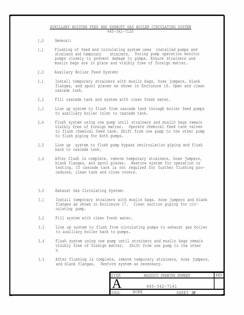
AUXILLARY BOISTER FEED AND EXHAUST GAS BOILER CIRCULATING SYSTEM445-342-7120
1.0 General:
1.1 Flushing of feed and circulating system uses installed pumps andstrainers and temporary strainers. During pump operation monitorpumps closely to prevent damage to pumps. Ensure strainers andmuslin bags are in place and visibly free of foreign matter.
2.0 Auxilary Boiler Feed System:
2.1 Install temporary strainers with muslin bags, hose jumpers, blankflanges, and spool pieces as shown in Enclosure 16. Open and cleancascade tank.
2.2 Fill cascade tank and system with clean fresh water.
2.3 Line up system to flush from cascade tank through boiler feed pumpsto auxiliary boiler inlet to cascade tank.
2.4 Flush system using one pump until strainers and muslin bags remainvisibly free of foreign matter. Operate chemical feed tank valvesto flush chemical feed tank. Shift from one pump to the other pumpto flush piping for both pumps.
2.5 Line up system to flush pump bypass recirculation piping and flushback to cascade tank.
2.6 After flush is complete, remove temporary strainers, hose jumpers,blank flanges, and spool pieces. Restore system for operation ortesting. If cascade tank is not required for further flushing pro-cedures, clean tank and close covers.
3.0 Exhaust Gas Circulating System:
3.1 Install temporary strainers with muslin bags, hose jumpers and blankflanges as shown in Enclosure 17. Clean suction piping for cir-culating pump.
3.2 Fill system with clean fresh water.
3.3 Line up system to flush from circulating pumps to exhaust gas boilerto auxiliary boiler back to pumps.
3.4 Flush system using one pump until strainers and muslin bags remainvisibly free of foreign matter. Shift from one pump to the otherpump.
3.5 After flushing is complete, remove temporary strainers, hose jumpers,and blank flanges. Restore system as necessary.
SIZE NASSSC0 DRAWING NUMBER REV
A 445-342-7141
SCALE: NONE SHEET 38
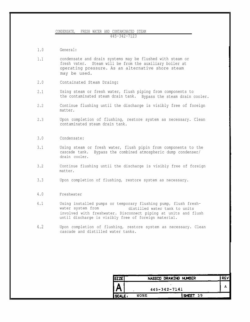
1.0
1.1
2.0
2.1
2.2
2.3
3.0
3.1
3.2
3.3
4.0
4.1
4.2
CONDENSATE, FRESH WATER AND CONTAMINATED STEAM445-342-7123
General:
condensate and drain systems may be flushed with steam orfresh vater. Steam will be from the auxiliary boiler atoperating pressure. As an alternative shore steammay be used.
Containated Steam Draing:
Using steam or fresh water, flush piping from components tothe contaminated steam drain tank. Bypass the steam drain cooler.
Continue flushing until the discharge is visibly free of foreignmatter.
Upon completion of flushing, restore system as necessary. Cleancontaminated steam drain tank.
Condensate:
Using steam or fresh water, flush pipin from components to thecascade tank. Bypass the combined atmospheric dump condenser/drain cooler.
Continue flushing until the discharge is visibly free of foreignmatter.
Upon completion of flushing, restore system as necessary.
Freshwater
Using installed pumps or temporary flushing pump, flush fresh-water system from distilled water tank to unitsinvolved with freshwater. Disconnect piping at units and flushuntil discharge is visibly free of foreign material.
Upon completion of flushing, restore system as necessary. Cleancascade and distilled water tanks.

AUXILLIARY BLOWDOWN AND S Y S T E M 445-342-7M1
1.0 General:
1.1 Flushing of auxiliary boiler blowdown piping, auxiliary boiler,and exhaust gas boiler escape steam and shore and steam relief pip-ing will be conducted prior to operation of the auxiliary boileror exhaust gas boiler.
1.2 Air will be used to verify blowdown and escape stem piping is freeof obstructions and debris. Normal operating pressure of 102 paigshould not be exceeded.
2.0 Auxiliary Boiler Blowdown Pipings
2.1 Disconnect blowdown piping downstream of the boiler blowdown valves.Connect air supply to surface or bottom blowdown piping.
2.2 Blowdown piping to bilge drains. Use caution to prevent injuryCo personnel or damage to equipment from air escaping from drain.Use minimum air pressure to verify piping is clean. Continue blow-down until discharge is visibly free of foreign matter.
2.3 Shift air blowdown to other bloWdown piping connection. Blow airthrough to drain until discharge is visibly free of foreign matter.
2.4 Blowdown piping overboard to verify hull valves are free of obstruc-tions and debris. Take precautions to ensure no personnel are work-ing in the area of the hull discharge whether ship is in dock orwaterborne. Continue blowdown for a sufficient period of time toensure piping is clean.
2.5 If waterborne and discharge is below waterline on completion ofblowdown, bleed off air pressure, shut hull valves, and crack openbilge drain. No leakage past hull valves should be observed.
2.6 Upon completion of blowdown, restore system as necessary.
3.0 Anxiliary Boiler, Exhaust Gas Boiler Escape Steam, and Shore SteamRelief Valve Pipings
3.1 Visually check escape steam and relief valve piping are free ofobstructions and debris. If piping can not be determined to beclear, blowdown with air as described below.
SIZE NASSCO DRAWING NUMBER REV
A 445-342-7141 A
SCALE : NONE SHEET 40
3.2 Disconnect piping downstream of boiler safety valve or relief valve.Blow-out escape and relief piping from engine room to stack or fromstack to engine room. Take precautions to ensure discharge of airdoes not injure personnel or damage equipment. Use minimum airpressure to verify piping is clear.
3.3 After auxiliary boiler and exhaust gas boiler escape steam and shoresteam relief valve piping have been blown-out, restore systems asnecessary.
SIZE NASSCO DRAWING NUMBER REV
A 445-342-7141 A
I
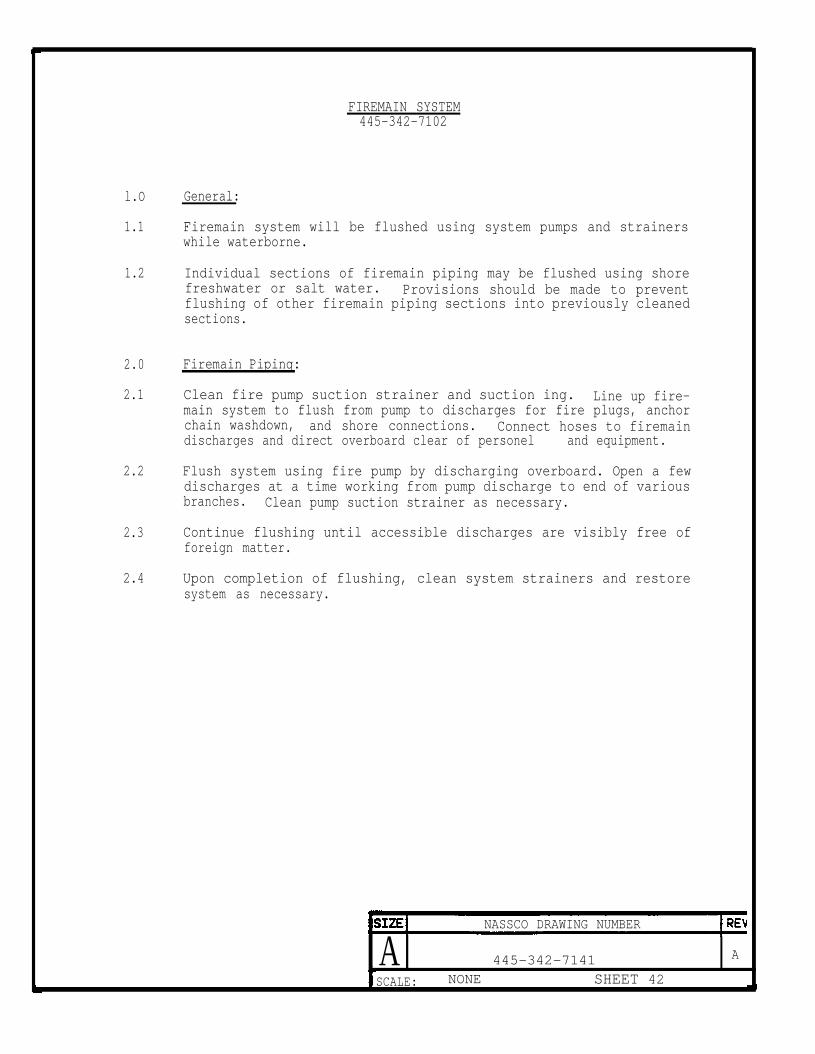
FIREMAIN SYSTEM445-342-7102
l.O
1.1
1.2
2.0
2.1
2.2
2.3
2.4
General:
Firemain system will be flushed using system pumps and strainerswhile waterborne.
Individual sections of firemain piping may be flushed using shorefreshwater or salt water. Provisions should be made to preventflushing of other firemain piping sections into previously cleanedsections.
Firemain Piping:
Clean fire pump suction strainer and suction ing. Line up fire-main system to flush from pump to discharges for fire plugs, anchorchain washdown, and shore connections. Connect hoses to firemaindischarges and direct overboard clear of personel and equipment.
Flush system using fire pump by discharging overboard. Open a fewdischarges at a time working from pump discharge to end of variousbranches. Clean pump suction strainer as necessary.
Continue flushing until accessible discharges are visibly free offoreign matter.
Upon completion of flushing, clean system strainers and restoresystem as necessary.
NASSCO DRAWING NUMBER
A 445-342-7141 A
SCALE: NONE SHEET 42
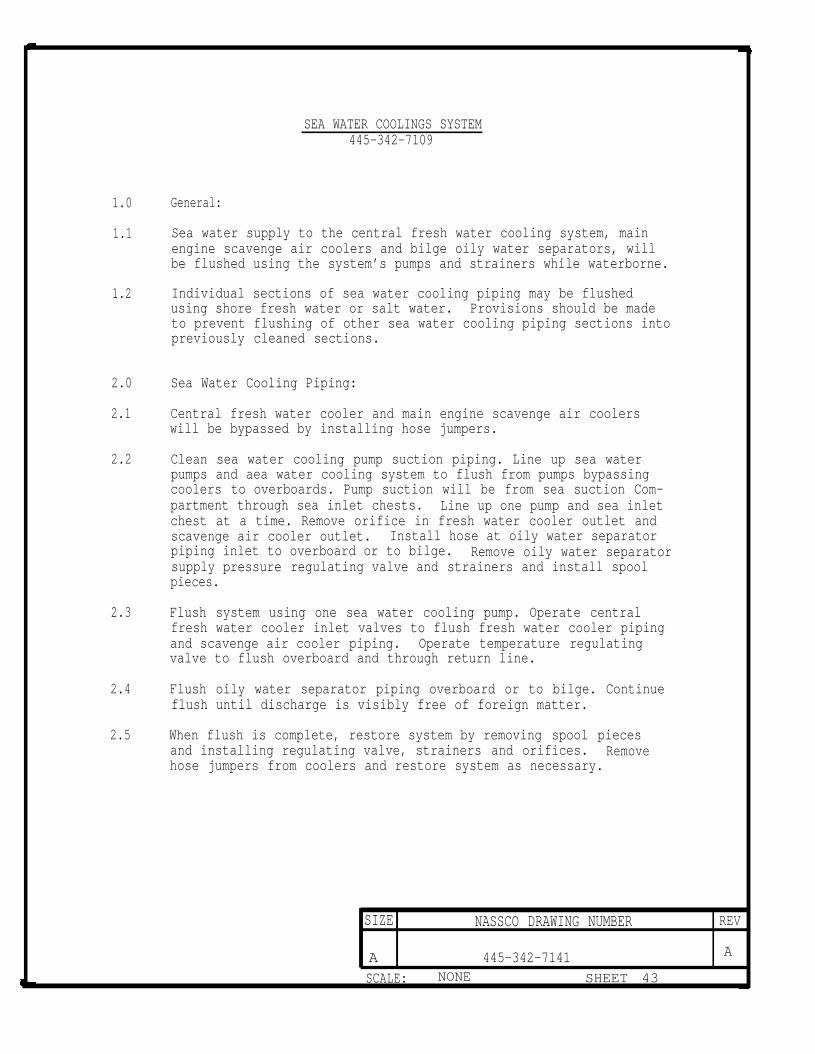
SEA WATER COOLINGS SYSTEM445-342-7109
1.0 General:
1.1 Sea water supply to the central fresh water cooling system, mainengine scavenge air coolers and bilge oily water separators, willbe flushed using the system’s pumps and strainers while waterborne.
1.2 Individual sections of sea water cooling piping may be flushedusing shore fresh water or salt water. Provisions should be madeto prevent flushing of other sea water cooling piping sections intopreviously cleaned sections.
2.0 Sea Water Cooling Piping:
2.1 Central fresh water cooler and main engine scavenge air coolerswill be bypassed by installing hose jumpers.
2.2 Clean sea water cooling pump suction piping. Line up sea waterpumps and aea water cooling system to flush from pumps bypassingcoolers to overboards. Pump suction will be from sea suction Com-partment through sea inlet chests. Line up one pump and sea inletchest at a time. Remove orifice in fresh water cooler outlet andscavenge air cooler outlet. Install hose at oily water separatorpiping inlet to overboard or to bilge. Remove oily water separatorsupply pressure regulating valve and strainers and install spoolpieces.
2.3 Flush system using one sea water cooling pump. Operate centralfresh water cooler inlet valves to flush fresh water cooler pipingand scavenge air cooler piping. Operate temperature regulatingvalve to flush overboard and through return line.
2.4 Flush oily water separator piping overboard or to bilge. Continueflush until discharge is visibly free of foreign matter.
2.5 When flush is complete, restore system by removing spool piecesand installing regulating valve, strainers and orifices. Removehose jumpers from coolers and restore system as necessary.
SIZE NASSCO DRAWING NUMBER REV
A 445-342-7141 A
SCALE: NONE SHEET 43

RALLAST AND HEELING SYSTEM445-342-7116
1.0
1.1
2.0
2.1
3.0
3.1
3.2
4.0
4.1
General:
Ballast system will be flushed using system pumps and eductors.Clean all ballast tanks. Clean tanks after all flushing operationsare complete. Check that suction/discharge bellmouths are clear.
Fire/Ballast Pump Suction and Discharge Pipings:
Clean auction piping from sea suction compartment. Align systemand operate one fire/ballast pump to flush from sea suction compart-ment overboard through eductor and then through priming bottle.Repeat for other pump.
BallastTank piping:
Partially fill forepeak ballast tank with sea water using fire/ballastpump to flush ballast piping into tank. Secure flush, dewater tankwith portable pump, and clean tank.
Partially fill one ballast tank in Hold No. 7 with fire/ballastpump. Secure flush, dewater tank using portable pump, and cleantank.
Heeling Pipings
Visually inspectmatter.
heeling piping to verify piping is free of foreign
SIZE NASSCO DRAWING_NUMBER REV
445-342-7141 A
SCALE: NONE SHEET 44

LOW TEMPERATURE FRESH WATER COOLING SYSTEM445-342-7107
1.0 General;
1.1 All fresh water cooling piping will be flushed with fresh water.
1.2 Flushing will be conducted using installed service pumps and tem-porary strainers. Install hose jumpers to bypass all air condition-ing units, condensers, coolers and air compressors during flushing.
2.0 Central Resh Water Coolimg Piping:
2.1 Remove spool piece and install temporary strainer with muslin bagin pump suction piping.
2.2 Remove all control and regulating valves or devices which can trapsediment and install spool pieces.
2.3 Fill system with fresh water. Expansion tank in high temperaturefresh water cooling system may be used. Line Up system to flushentire system or segments of system.
2.4 Continue flushing until temporary strainers and muslin bags arevisibly free of foreign matter. During flushing blowdown installedstrainer periodically to remove sediment. Flushing is not completeuntil all strainers, temporary and installed are visibly free offoreign matter. Operate regulating valve bypasses during flushto flush bypass piping.
2.5 Upon completion of flush, remove temporary strainers, hose jumpers,and spoo1 pieces. Restore system as necessary.
SIZE NASSCO DRAWING NUMBER REV
445-342-7141 A
SCALE: NONE SHEET 45
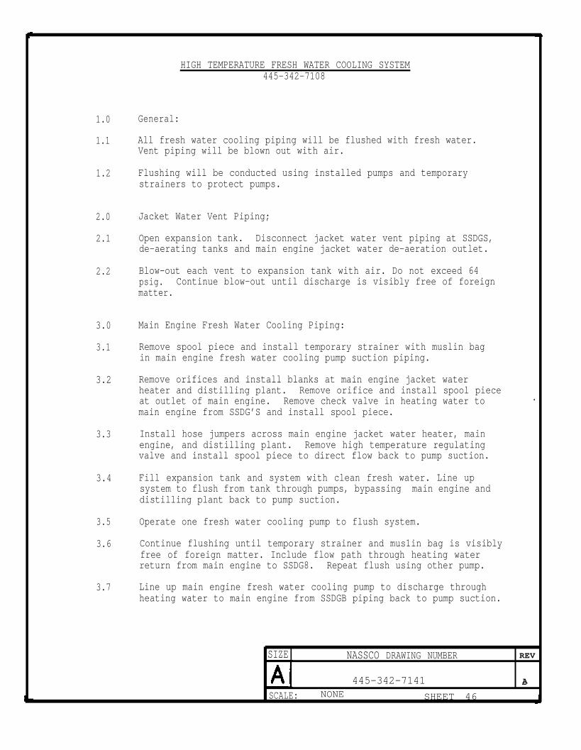
HIGH TEMPERATURE FRESH WATER COOLING SYSTEM445-342-7108
1.0 General:
1.1 All fresh water cooling piping will be flushed with fresh water.Vent piping will be blown out with air.
1.2 Flushing will be conducted using installed pumps and temporarystrainers to protect pumps.
2.0 Jacket Water Vent Piping;
2.1 Open expansion tank. Disconnect jacket water vent piping at SSDGS,de-aerating tanks and main engine jacket water de-aeration outlet.
2.2 Blow-out each vent to expansion tank with air. Do not exceed 64psig. Continue blow-out until discharge is visibly free of foreignmatter.
3.0 Main Engine Fresh Water Cooling Piping:
3.1 Remove spool piece and install temporary strainer with muslin bagin main engine fresh water cooling pump suction piping.
3.2 Remove orifices and install blanks at main engine jacket waterheater and distilling plant. Remove orifice and install spool pieceat outlet of main engine. Remove check valve in heating water to .
main engine from SSDG’S and install spool piece.
3.3 Install hose jumpers across main engine jacket water heater, mainengine, and distilling plant. Remove high temperature regulatingvalve and install spool piece to direct flow back to pump suction.
3.4 Fill expansion tank and system with clean fresh water. Line upsystem to flush from tank through pumps, bypassing main engine anddistilling plant back to pump suction.
3.5 Operate one fresh water cooling pump to flush system.
3.6 Continue flushing until temporary strainer and mus1in bag is visiblyfree of foreign matter. Include flow path through heating waterreturn from main engine to SSDG8. Repeat flush using other pump.
3.7 Line up main engine fresh water cooling pump to discharge throughheating water to main engine from SSDGB piping back to pump suction.
SIZE NASSCO DRAWING NUMBER REV
445-342-7141 A—SCALE: NONE SHEET 46
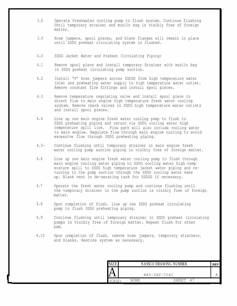
3.8
3.9
4.0
4.1
4.2
4.3
4.4
4.5-
4.6
4.7
4.8
4.9
4.10
Operate freshwater cooling pump to flush system. Continue flushingUntil temporary strainer and muslin bag is visibly free of foreignmatter.
Hose jumpers, spool pieces, and blank flanges will remain in placeuntil SSDG preheat circulating system is flushed.
SSDG Jacket Water and Preheat Circulating Piping:
Remove spool piece and install temporary Strainer with muslin bagin SSDG preheat circulating pump suction.
Install “Y” hose jumpers across SSDGS from high temperature waterinlet and preheating water supply to high temperature water outlet.Remove constant flow fittings and install spool pieces.
Remove temperature regulating valve and install spool piece todirect flow to main engine high temperature fresh water coolingsystem. Remove check valves in SSDG high temperature water outletsand install spool pieces.
Line up one main engine fresh water cooling pump to flush toSSDG preheating piping and return via SSDG cooling water hightemperature spill line. Flow path will also include cooling waterto main engine. Regulate flow through main engine cooling to avoidexcessive flow through SSDG preheating piping.
Continue flushing until temporary strainer in main engine freshwater cooling pump suction piping is visibly free of foreign matter.
Line up one main engine fresh water cooling pump to flush throughmain engine cooling water piping to SSDG cooling water high temp-
erature spill to SSDG high temperature jacket water piping and re-turning to the pump suction through the SSDG cooling water makeup. Blank vent in de-aerating tank for SSDGS if necessary.
Operate the fresh water cooling pump and continue flushing untilthe temporary strainer in the pump suction is visibly free of foreignmatter.
Upon completion of flush, line up one SSDG preheat circulatingpump to flush SSDG preheating piping.
Continue flushing until temporary strainer in SSDG preheat circulatingpumps is visibly free of foreign matter. Repeat flush for otherpump.
Upon completion of flush, remove hose jumpers, temporary strainers,and blanks. Restore system as necessary.
SIZE NASSCO DRAWING NUMBER REV
A 445-342-7141 A
SCALE: NONE SHEET 47

DISTILLING PLANT SERVICES445--342-7126
l.O General:
1.1 Feed and brine overboard piping will be flushed using ejector pumpfrom sea suction compartment. Distillate piping to potable watertanks will be flushed with fresh water. Distillate piping to pot-able water tanks will be chlorinated with the potable water system.
1.2 Ejector pump auction piping to sea suction compartment will bechecked prior to final connection to verify no debris is left inpiping.
2.0 Feed and Brine Orerboard Piping:
2.1 Install hose jumper to bypass distilling plant from seawater inletto overboard piping connection.
2.2 Line up system to take suction from sea suction compartment anddischarge overboard. Check that area near overboard discharge isclear of personnel and equipment.
2.3 Flush system using ejector pump for 30 minutes or until discharge,if visible, is clear.
2.4 After completion of flushing remove hose jumpers and restore systemas necessary.
3.0 Distillate Piping:
3.1 Open and clean potable water and distilled water tanks. Disconnectdistillate piping at distillate outlet and connect fresh watersupply
3.2 Flush piping to each tank with fresh water until discharge isvisibly free of foreign matter.
3.3 Upon completion of flush, dewater tanks, clean and install covers.Remove fresh water hose.
SIZE NASSCO DRAWING NUMBER REV
445-342-7141
SCALE: NONE SHEET 48

1.0
1.1
1.2
2.0
2.1
2.2
2.3
2.4
2.5
2.6
POTABLE WATER SYSTEM445-331-4503
General:
All potable water tanks, piping, fixtures, and pumps for stowageor use of potable water will be disinfected.
Disinfection will be done after all work on the potable water sys-tem is complete. After disinfection the potable water tanks andsystem will not be opened. If necessary to reopen potable watertanks or the potable water system, disinfection will be repeated.
Potable Water Pipimg:
If not already accomplished open and clean potable water tanks byhand.
Fill the potable water tank and piping with potable water from dock-side. Fill system using all deck connections.
Flush potable water system by operating system pumps and flushingthrough to each outlet. Flush until discharges are visibly freeof foreign matter.
After flushing has been completed, refill system including distil-late piping to potable water tanks and chlorinate for a concentra-
tion of 50 ppm. Operate system pumps and circulate chlorinatedWater throughout system. Operate outlets nearest the storage tanksto obtain chlorinated water at each fixture or opening. Continuethe process outward from the tanks until all fixtures and openingshave been flushed with chlorinated water. Refill the potable watertanks and dechlorinate as necessary to maintain the 50 ppm concentra-tion.
Fill system and tanks to overflowing with 50 ppm chlorinated waterand allow system to stand filled far four hours.
After four hours, drain and flush system with potable water untilthe chlorine taste at fixtures and openings is not objectionable.
NASSCO DRAWING NUMBER
A 445-342-7141 A
SCALE: NONE SHEET 49

SHIP SERVICER SYSTEM445-342-7118
1.0 Gemeral:
1.1 Service air piping will be flushed using air from the ship serviceair compressor, starting air compressors or shore air at 125 PSIGmaximum reduced pressure.
2.0 Ship Service Air:
1.1 Compressor/Receiver Piping:
2.1.1 Operate compressor to supply air to ship service air system orconnect air hose to compressor outlet. Air pressure should beapproximately 125 psig.
2.1.2 Blowdown drains in piping and receiver until the discharge isvisibly free of foreign matter.
2.1.3 Upon completion of blow-out, clean air receiver strainer andrestore system as necessary.
2.2 Second Deck and Main Deck Outlets:
2.2.1 Remove filter/separators at hose connection. Operate compressoror use air hose connected to system piping to blow-out each airconnection. Start at engine room and blow-out through each airconnection and drain in ship service air mains.
2.2.2 Continue each air connection blow-out until the discharge is visi-
bly free of foreign matter. Blow-out each connection and drainon the second, main, and forecastle deck.
2.2.3 For the chemical bilge pump, disconnect air supply to pump andblow-out until the discharge is visibly free of foreign matter.
2.2.4 Upon completion of blow-out clean and install filter/separator8.
2.3 Machinery Space Ship Service Air:
2.3.1 Remove filter/8eparator at hose connections. Operate compressoror use air hose connected to system piping to blow-out each airconnection. Start at compressor connection to VertiCal supp1ymain and blow-out each air connection and pump supply.
SIZE NASSCO DRAWING NUMBER REV
445-342-7141 A
SCALE: NONE SHEET 50

2.3.2
2.3.3
2.3.4
Continue each air connection blow-out until the discharge is viSi-
blY free of foreign matter. Blow-out each air connection at eachlevel.
For the lube oil transfer pump and sludge transfer pump, dis-connect the air supply to the pump and blow-out until the dis-charge is visibly free of foreign matter.
Upon completion of blow-out, clean and install filter/separators.
SIZE NASSCO DRAWING NUMBER REV
445-342-7141 A
SCALE: NONE SHEET 51
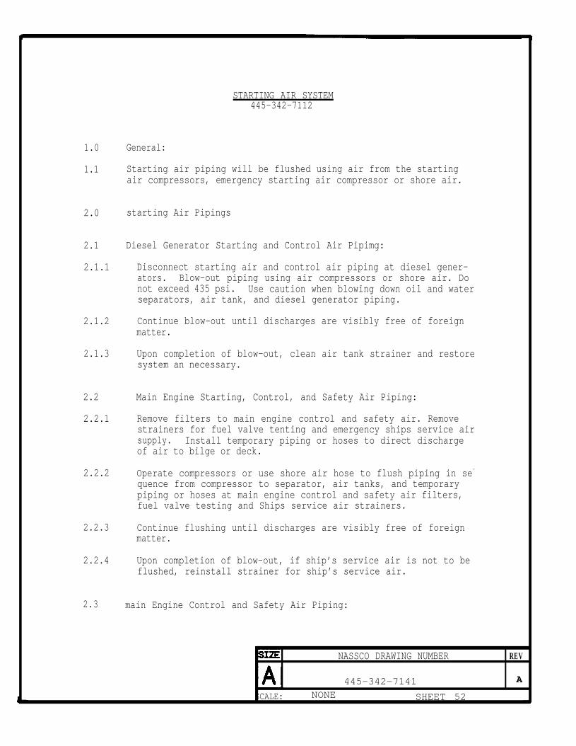
STARTING AIR SYSTEM445-342-7112
1.0 General:
1.1 Starting air piping will be flushed using air from the startingair compressors, emergency starting air compressor or shore air.
2.0 starting Air Pipings
2.1 Diesel Generator Starting and Control Air Pipimg:
2.1.1 Disconnect starting air and control air piping at diesel gener-ators. Blow-out piping using air compressors or shore air. Donot exceed 435 psi. Use caution when blowing down oil and waterseparators, air tank, and diesel generator piping.
2.1.2 Continue blow-out until discharges are visibly free of foreignmatter.
2.1.3 Upon completion of blow-out, clean air tank strainer and restoresystem an necessary.
2.2 Main Engine Starting, Control, and Safety Air Piping:
2.2.1 Remove filters to main engine control and safety air. Removestrainers for fuel valve tenting and emergency ships service airsupply. Install temporary piping or hoses to direct dischargeof air to bilge or deck.
2.2.2 Operate compressors or use shore air hose to flush piping in se-
quence from compressor to separator, air tanks, and temporarypiping or hoses at main engine control and safety air filters,fuel valve testing and Ships service air strainers.
2.2.3 Continue flushing until discharges are visibly free of foreignmatter.
2.2.4 Upon completion of blow-out, if ship’s service air is not to beflushed, reinstall strainer for ship’s service air.
2.3 main Engine Control and Safety Air Piping:
NASSCO DRAWING NUMBER REV
445-342-7141 A
SCALE: NONE SHEET 52

1.0
1.1
2.0
2.1
2.2
2.3
2.4
CONTROL AIR SYSTEM445-342-7119
General
Control air piping will be flushed using air from the startingair compressors emergency starting air compressor, ships serviceair compressor Or shore air at 125 PSIG maximum reduced pressure.
control Air Pipimg
Install jumper hose to bypass dehydrator. Disconnect controlair piping at each component served. Remove in-line filters andstrainers.
Using air from compressors or clean, dry, oil free shore air,blowdown receivers and control piping working from receiversoutward.
Continue blow-out until discharges are visibly free of foreignmatter.
Upon completion of blow-out, clean and install filters andstrainers, restore systems as necessary.
SIZE NASSCO DRAWING REV
j 4 4 5 - 3 4 2 - 7 1 4 1 A
SCALE: NONE SHEET 54
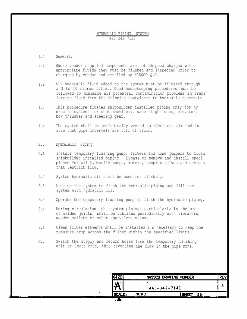
1.0
1.1
.1.2
1.3
1.4
2.0
2.1
2.2
2.3
2.4
2.s
2.6
2.7
HYDRAULIC PIPING SYSTEM445-342-7128
General:
Where vendor supplied components are not shipped charged withappropriate fluids they must be flushed and inspected prior tocharging by vendor and verified by NASSCO Q.A.
All hydraulic fluid added to the system must be filtered througha 3 to 10 micron filter. Good housekeeping procedures must befollowed to minimize all potential contamination problems in trans-
ferring fluid from the shipping containers to hydraulic reservoir.
This procedure flushes shipbuilder installed piping only for hy-draulic systems for deck machinery, water tight door, elevator,bow thruster and steering gear.
The system shall be periodically vented to bleed out air and in-
sure that pipe intervals are full of fluid.
Eydralalic Piping
Install temporary flushing pump, filters and hose jumpers to flushshipbuilder installed piping. Bypass or remove and install spoolpieces for all hydraulic pumps, motors, complex valves and devicesthat restrict flow.
System hydraulic oil shall be used for flushing.
Line up the system to flush the hydraulic piping and fill thesystem with hydraulic oil.
Operate the temporary flushing pump to flush the hydraulic piping.
During circulation, the system piping, particularly in the areaof welded joints, shall be vibrated periodically with vibrators,wooden mallets or other equivalent means.
Clean filter elements shall be installed l s necessary to keep thepressure drop across the filter within the specified limits.
Switch the supply and return hosesunit at least-once, thus reversing
from thethe flow
temporary flushingin the pipe runs.

2.8 When the filter elements are free of foreign matter, obtain a rep-
resentative oil sample and send to a laboratory for a particulatecount. The sample shall meet the cleanliness standard of SAE,Class 5. Repeat flushing procedure until cleanliness standard ismet.
2.9 After flushing has been completed, remove the temporary flushingunit, blank flanges, hose jumpers, hose connections, and clean allopenings. Restore the system as necessary.
SIZE NASSCO DRAWING NUMBER REV
A 445-342-7141A

1.0 Deck Drains and
1.1 Blow out drainsopen.
Miscellaneous Drains
with air or flush with Water to verify drains are
NASSCO DRAWING NUMBER REv
A 445-342-7141 A
SCALE: NONE SHEET 57

1.0
1.1
2.0
2.1
2.2
3.0
3.1
3.2
4.0
4.1
4.2
5.0
5.1
CO2SYSTEM
445-342-7103
Generals
C02 piping will be blown out with clean filtered air prior toconnecting C02 bottles, manifolds, distribution piping and mainengine scavenge air C0² piping.
Control Piping:
Blow-out cylinder control piping with air prior to connectingcylinders to control piping. Blow-out from manifold to cylinderconnection.
Continue blow-out until each control line is visibly free offoreign matter.
Discharge Manifold Piping:
Blow-out cylinder discharge manifold piping prior to connectingcylinders to discharge manifold. Blow-out from manifold tocylinder connection.
Continue blow-out until each discharge connection is visibly freeof foreign matter.
Distribution Piping:
Connect air supply to manifold outlet. Line up C02 system toblow-out individual piping lines to engine room and each hold.
Continue blow-out for each section until discharges are visiblyfree of free of foreign matter. Clean dirt traps. Check all outlets toverify nozzles are clear.
Main Enginw Scavenge Air CO2 Pipings
Blow-out main engine scavenge air c02 piping as described inParagraphs 3.0 and 4.0 up co main engine connection.
SIZE NASSCO DRAWING NUMBER REV
445-342-7141 A
SCALE: NONE SHEET 58

BILCK SYSTEM445-342-7110
1.0
1.1
1.2
2.0
2.1
2.2
2.3
2.4
2.5
2.6
2.7
2.8
General:
Sections of bilge piping will be flushed by filling bilgepockets with water and removing by use of an eductor or installedpumps.
Prior to flushing piping ensure bilge areas are clean. Cleambilge pockets, bilge wells, anti plate and rosebud strainers.
Bilge Eouaekeeping
Line up bilge housekeepingcompartment and dischargeuse hose jumper to bypassboard.
Flush bilge housekeeping
pump to take suctionoverboard via deckbilge separator unit
pump suction piping
on sea auctionshore connection orand discharge over-
until pump suctionstrainer remains visibly free of foreign matter.
Secure flush and line up bilge housekeeping pump to take suctionon bow thruster compartment bilge well.
Fill bilge well in bow thruster compartment using forward voidbilge eductor or hose. Take suction on this bilge well using thebilge housekeeping pump and discharging overboard. Operate eductoror hose to maintain water level in bilge well.
Continue flush until pump suction strainer is visibly free offoreign matter.
After flush is complete, line up system to flush oily water sep-arator piping to the overboard hull discharge if this was not donepreviously. Install hose jumpers across oily water separator andoil content monitor as necessary.
Flush
Afterclean
overboard piping through overboard hull discharge.
flush is complete, remove hose jumpers, restore system andall strainers.
A 445-342-7141 I

3.0
3.1
3.2
Main Biige piping:
Line up main bilge pump to take suction on sea suctionand discharge overboard.
compartment
Flush piping using main bilge pump until-pump suction strainer isvisibly free of foreign matter.

DIESEL ENGINES AND AUXILLIARY BOILER EXHAUST SYSTEM445-342-7117
1.0 Diesel Engines and Anxiliaxy Boiler Exhaust Piping:
1.1 The diesel engine and auxiliary boiler exhaust system will bevisually inspected for cleanliness prior to final connection ofpiping and ducting. Clean as necessary.
IZES REV
A 445-342-7141 A
SCALE: NONE SHEET 61
1.0
1.1
VENTS, SOUNDING TUBES AND OVERFLOW SYSTEMM5-342-7122
Vents, sounding TubeS, and Overflow Piping:
Blow-out vents, sounding tubes, and overflow with clean dry air.Use minimum pressure to prevent piping damage.
A 445-342-7141 A
SCALE: NONE SHEET 62
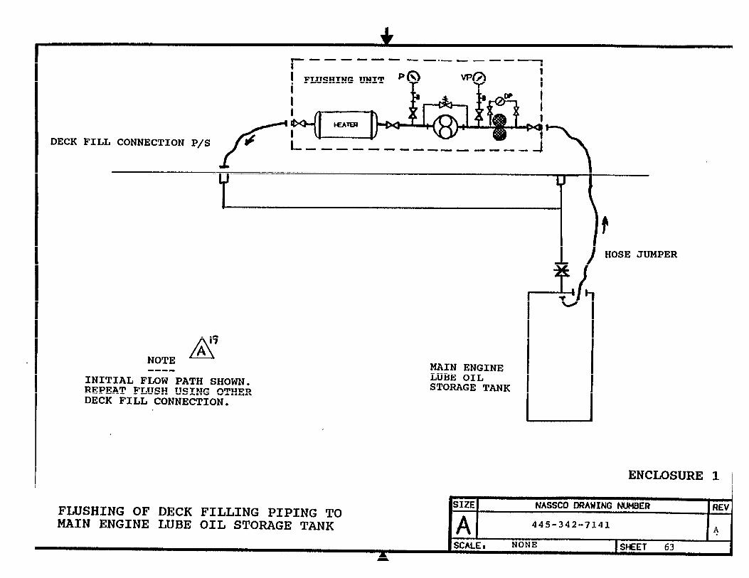


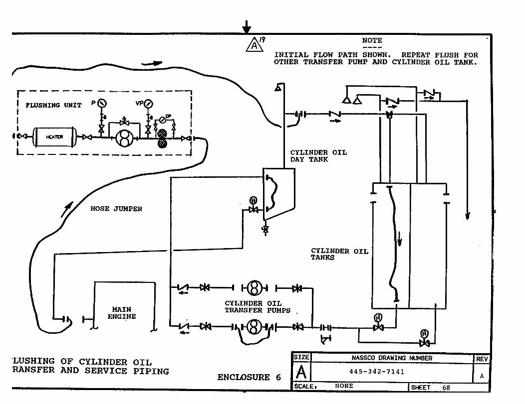

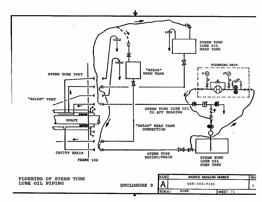


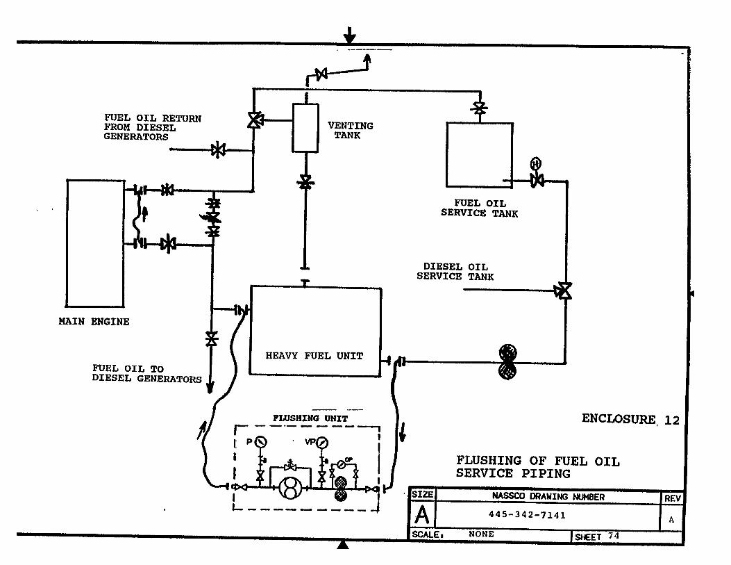


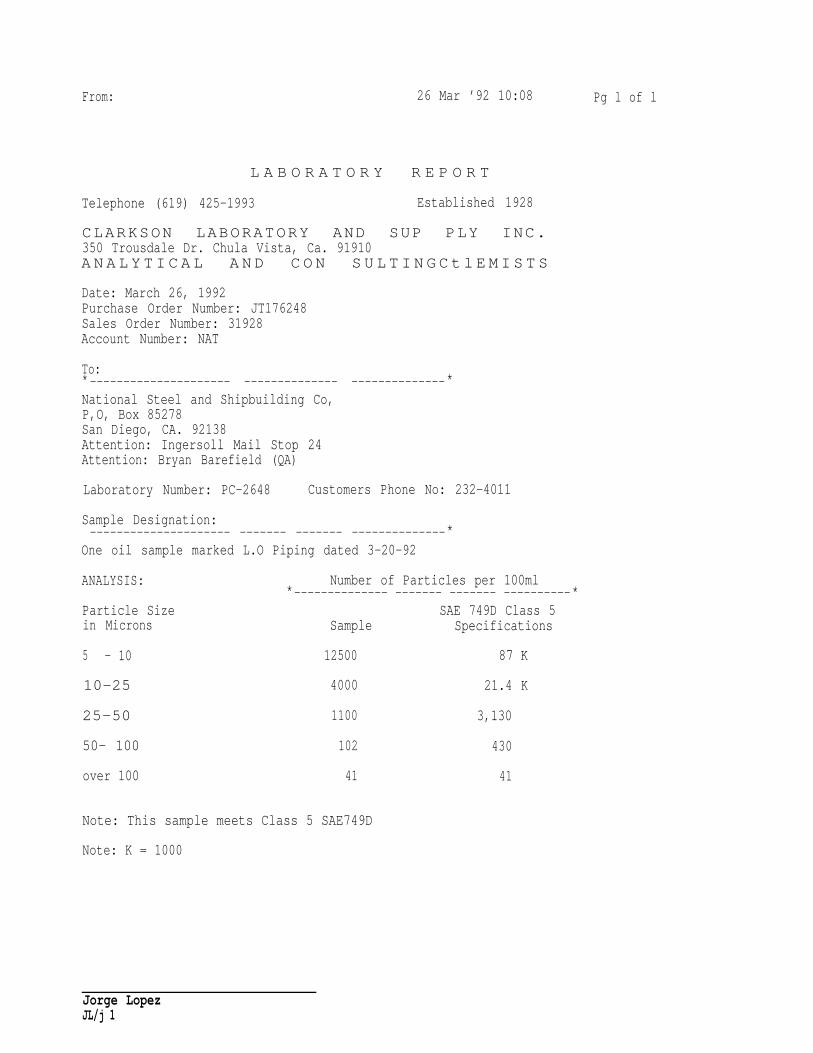
From: 26 Mar ’92 10:08 Pg l of l
L A B O R A T O R Y R E P O R T
Telephone (619) 425-1993 Established 1928
CLARKSON LABORATORY AND SUP PLY INC.350 Trousdale Dr. Chula Vista, Ca. 91910A N A L Y T I C A L A N D C O N S U L T I N G C t l E M I S T S
Date: March 26, 1992Purchase Order Number: JT176248Sales Order Number: 31928Account Number: NAT
To:*--------------------- -------------- --------------*National Steel and Shipbuilding Co,P,O, Box 85278San Diego, CA. 92138Attention: Ingersoll Mail Stop 24Attention: Bryan Barefield (QA)
Laboratory Number: PC-2648 Customers Phone No: 232-4011
Sample Designation:--------------------- ------- ------- --------------*
One oil sample marked L.O Piping dated 3-20-92
ANALYSIS: Number of Particles per 100ml*-------------- ------- ------- ----------*
Particle Size SAE 749D Class 5in Microns Sample Specifications
5 - 10 12500 87 K
10-25 4000 21.4 K
25-50 1100 3,130
50- 100 102 430
over 100 41 41
Note: This sample meets Class 5 SAE749D
Note: K = 1000
Jorge LopezJL/j 1


Additional copies of this report can be obtained from the National ShipbuildingResearch Program Coordinator of the Bibliography of Publications and Microfiche Index.You can call or write to the address or phone number listed below.
NSRP CoordinatorThe University of Michigan
Transportation Research InstituteMarine Systems Division
2901 Baxter Rd.Ann Arbor, MI 48109-2150
Phone: (313) 763-2465Fax: (313) 936-1081