automatic mesh generation - rit scholar works
TRANSCRIPT

Rochester Institute of TechnologyRIT Scholar Works
Theses Thesis/Dissertation Collections
5-1-1990
Automatic mesh generationAjay Garg
Follow this and additional works at: http://scholarworks.rit.edu/theses
This Thesis is brought to you for free and open access by the Thesis/Dissertation Collections at RIT Scholar Works. It has been accepted for inclusionin Theses by an authorized administrator of RIT Scholar Works. For more information, please contact [email protected].
Recommended CitationGarg, Ajay, "Automatic mesh generation" (1990). Thesis. Rochester Institute of Technology. Accessed from

Approved by:
AUTOMATIC MESH GENERATION
by
Ajay Garg
A Thesis Submitted
in
Partial Fulfillment
of the
Requirements for the Degree of
MASTERS OF SCIENCE
in
Mechanical Engineering
Prof. Richard S. Budynas
(Thesis Advisor)
Prof. Hany Ghoniem
Prof. Guy Johnson
Prof. Charles W. Haines
(Department Head)
DEPARTMENT OF MECHANICAL ENGINEERINGCOll..EGE OF ENGINEERING
ROCHESTER INSTITUTE OF TECHNOLOOYMAY 1990

Title of Thesis - "Automatic Mesh Generation"
I Ajay Garg hereby grant permission to the Wallace MemorialLibrary of R.I.T. to reproduce my thesis in whole or in part.Any reproduction will not be for commercial use or profit.
Date: 8/14/91
(Ajay Garg)

ABSTRACT
The objective of this thesis project is a study of Pre-Processors and
development of an Automatic Mesh Generator for Finite Element Analysis. The
Mesh Generator developed in this thesis project can create triangular finite
elements from the geometric database of Macintosh Applications. The user is
required to give the density parameter to the program for mesh generation. The
research is limited to Mesh Generators of planar surfaces. Delauny
Triangulation method maximizes the minimum angles of a triangle. Watson's
Delauny Triangulation method can mesh only the 'convexhull'
of a set of
nodes. This algorithm has been modified to create triangular elements in
convex and non-convex surfaces. The surfaces can have holes also. A node
generation algorithm to place nodes on and inside a geometry has been
developed in this thesis project. The mesh generation is very efficient and
flexible.
Geometric modeling methods have been studied to understand and integrate
the Geometric Modeler with the Finite Element Mesh Generator.
Expert Systems can be integrated with Finite Element Analysis. This will make
Finite Element Method fully automatic. In this thesis project, Expert Systems in
Finite Element Analysis are reviewed. Proposals are made for future approach
for the integration of the two fields.
IV

ACKNOWLEDGEMENTS
This study acknowledges with sincere gratitude and thanks the patience and
guidance of major advisor, Dr. Richard Budynas.
Special indebtedness is extended to Committee Members, Dr. Hany Ghoniem
and Prof. Guy Johnson for spending their valuable time and effort in reviewing
this work.
Thanks are due to Dr. Renato Perruchio and Mr. Nicholos Sapidis of the
University of Rochester, for their invaluable suggestions and guidance
Mr. Jim Russell of the Rochester Institute of Technology is acknowledged for his
efficient work in coding the algorithm of the writer.
Special thanks are extended to staff members of Watson Memorial Library of
the Rochester Institute of Technology, through whose special library resources
material for this study was obtained readily.
Thanks are extended to Amita, my wife for her patience and encouragement
and I acknowledge the effort of my parents, Mrs. Sarojini Garg and Mr.
Ramanand Garg, whose constant support made me what I am today.
Thanks to Dr. Ishrat Mustafa for scrutinizing the"nitty of this thesis.
Last but not the least deep gratitude is expressed to "Mama", "Mami", Bharat,
and friends. Their warm encouragemnt and much kindness made this task
easier.

TABLE OF CONTENTS
Page
ABSTRACT iv
ACKNOWLEDGEMENTS v
LIST OF FIGURES x
LIST OF TABLES xiv
LIST OF SYMBOLS xiv
Chapter
1. INTRODUCTION 1
1.1 Finite Element Modeling in Mechanical Design 1
1 .2 Pre-Processors 4
1.3 Density and Shape of Finite Elements 7
1.4 History of Pre-Processors 10
1.5 Automatic Pre-Processors 13
1.6 Thesis Objective - Automatic Mesh Generation 16
1.7 Thesis Organization 18
2. GEOMETRIC MODELING 22
2.1 Introduction 22
vi

2.2 Geometric Modelers 24
2.3 Geometric Modeling 27
2.3.1 Curve Generation 28
2.3.2 Bezier Form of PC Curve 36
2.3.3 B Spine Curves 39
2.4 Surface Generation 41
2.4.1 Quadric Surfaces 46
3. AUTOMATIC MESH GENERATION - REVIEW OF RELATED
LITERATURE 49
3.1 Mesh Generation Methods 50
3.2 Interactive Schemes 50
3.2.1 Laplacian Method 52
3.2.2 Isoparametric Mapping Method 55
3.2.3 Transfinite Mapping Method 57
3.2.4 Discrete Form Of Transfinite Mappings 62
3.3 Automatic Mesh Generation 65
3.3.1 Topology based Algorithms 66
3.3.2 Heirarchical Decomposition Algorithms 72
3.3.3 Triangulation 76
3.3.3.1 Lewis and Robinson Method 77
3.3.3.2 Triquamesh Algorithm 81
3.3.3.3 Lo's Method 84
3.3.3.4 Sadek's Algorithm 87
3.3.3.5 Bykat's Method 92
3.4 Delauny Triangulation 92
3.4.1 Nearest Neighbor Search by loci proximity 95
vii

3.4.2 Properties of Delauny Triangulation 98
3.4.2.1 Optimal Equiangularity Property 98
3.4.2.2 Empty Circumcircle Property 99
3.4.3 Dgenraciesin Delauny Triangulations 101
3.4.4 Delauny Treangulation Algorithms 102
4. AUTOMATIC MESH GENERATION BY MODIFIED WATSON'S
METHOD 104
4.1 Node Generation 105
4.2 Watson's Delauny Triangulation Algorithm 108
4.3 Modifications onWatson's Algorithm 1 1 4
4.4 Results 116
4.5 Discussion 124
4.6 Conclusion 125
5. EXPERT SYSTEM IN FINITE ELEMENT ANALYSIS 127
5.1 Artificial Intelligence 127
5.2 Expert Systems 128
5.3 Components of an Expert System 129
5.3.1 Knowledge Base 130
5.3.2 Inference Engine 130
5.3.3 User Interface 133
5.4 Developing an Expert System 133
5.4.1 Identification 134
5.4.2 Conceptualization 135
5.4.3 Formalization 135
vm

5.4.4 Implementation 136
5.4.5 Testing 136
5.5 Expert System in Finite Element Analysis 136
5.6 The Expert System Approach 139
5.7 Suggestions for the Knowledge base of an Expert Finite Element
Modeler 141
5.7.1 Element Selection 142
5.7.2 Node Placement 143
5.7.3 Mesh Generation 144
5.7.4 Mesh Refinement 144
5.8 Overview of an Expert System 145
5.9 Conclusion 148
REFERENCES 149
APPENDIX 156
IX

LIST OF FIGURES
Figure Page
1.1 Flowchart Engineering System 2
1.2 Two-Dimensional Finite Element Model 4
a) Plate with a hole
b) Finite Element mesh of quarter plate
1 .3 Pre-Processor Flow Chart 8
1.4 Quadrilateral Finite Elements 12
a) Elements with good shapes
b) Elements with poor shapes
1.5 Finite Element Mesh Densities 12
a) Coarse mesh
b) Fine mesh
1.6 A Rectangular Plate with End Moments 13
2.1 Geometric Modeling Methods 26
a) Unambiguous wireframe model
b) Ambiguous wireframe model
c) Surface model
d) Solid model
2.2 Solid Modeling Methods 27
2.3 Two Parametric Curve Segment 30
2.4 Elements of a Space Curve 33
2.5 Effect of Tangent Vector Magnitude on Curve Shape 35
2.6 Variation of Bezier Curves by Intermediate Points 37
2.7 PC Equivalent of a Cubic Bezier Curve 39

2.8 Parameters of a Bi-Cubic Patch 42
2.9 Nomenclature of a Bi-Cubic Surface 44
3.1 Point Location by Laplacian Method 52
3.2a Laplacian mesh 53
3.2b Rectangular mesh 53
3.3 Curvilinear Coordinates for Quadrilateral Isoparametric Mapping .. 56
3.4 Linear Loftinhg Projector P 59
3.5 Region F to be Mapped by Bilinear Projector 59
3.6 Sum and Product of a Bilinear Projector 61
a) Bilinear projector P-|
b) Bilinear projector P2
c) Bilinear projector P1P2
d) Bilinear projector P1+P2
3.7 Rectangular Network of Intersecting Curves 63
3.8 Vertex Removal Operator 69
3.9 Vertex Removal with Edge Split 70
a) First edge split
b) Mesh before removing vertex
c) Mesh after removing vertex
d) Final mesh
3.10 Edge Removal Operator 70
a) Removal of edge 1 -2
b) Final mesh
3.11 Hierarchical Approximation of an Object 73
3.12 Tree Structure of Quadtree Approximation 73
XI

3.13a Tree structure of data records 74
3.13b Hierarchical structure for a finite element model 74
3.14 Subdivision of a Domain 79
3.15 Information Used for Calculating k 79
3.16 Triangulation by Triquamesh Technique 82
3.17 Triangulation by Lo's Method 87
3.18 Stages of Element Generation in Sadek's Method 88
3.19 Generation of a Node by Sadek's Method 89
3.20 Tesselations of a Plane 93
3.21 Convex Hull of a Set of Points 95
3.22a Half Planes and Locus of Intersection of Half Planes 96
3.22b Vertices and Half Planes of Dirichlet Tesselations 96
3.23 Delauny Triangulation with Dirichlet Tesselation 97
3.24 Delauny Triangulation and General Triangulation 98
3.25 Empty Circumcircle of a Delauny Triangle 99
3.26 Empty circumdisks of a Set of Nodes 100
3.27 Degenracy of Delauny Triangulation 101
4.1 Node Generation 106
4.2 The Enclosing Triangle of Nodes 109
4.3 Delauny Triangulation of a Node 110
4.4 A Node for Insertion and Empty Circumcircles 111
4.5 The Insertion Polygon 111
4.6 New Triangulation 112
4.7 A Non-convex Geometry with Hole 113
xii

4.8 Delauny Triangulation byWatson's Method 113
4.9 Identifying External Triangles 114
4.10 Delauny Triangulation of a Square 117
4.11 Triangulation of a 'ConvexHull'
117
4.12 Node Generation on an Irregular Boundry 119
4.13 Automatic Meshed and Remeshed Elements 120
a) Automatic mesh
b) Node deleted
c) Node added
4.14 High Node and Mesh Densities 121
a) Generated nodes
b) Generated mesh
4.15 Mesh of a Geometry with a Hole 122
4.16 An Irregular Geometry with Holes 123
4.17 Mesh of an Irregular Geometry with Holes 123
Flowchart
5.1 Development Stages of an Expert System 134
5.2 Data Flow through FACS Finite Element Expert System 146
Xlll

LIST OF TABLES
Table Page
1.1 Varying Aspect Ratio on Finite Element Codes
1 .2 Varying Element Density on Finite Element Codes
14
14
LIST OF SYMBOLS
[] Matrix
nT Tranpose of a Matrix
Bold letters in equations Vector
Bar over letters Vector
FEM Finite Element Method
FEA Finite Element Analysis
PDA
pc Parametric Cubic
CAD Computer Aided Design
SDRC Structural Dynamics Research Corporation
DT Delauny Triangulation
DIT Dirichlet Tessellation
XIV

CHAPTER 1
INTRODUCTION
1.1 FINITE ELEMENT MODELING IN MECHANICAL DESIGN
Modern engineers face monumental tasks when developing designs required
to survive a broad range of extreme conditions and consumer demands. Added
to this task are concerns for product safety and competition in commercial
markets.
A mechanical design involves the engineer's ingenuity and analysis expertise.
Typically, the design of a product from concept to finalization goes through the
steps shown in figure (1.1) HI.
These steps are as follows :
1. Concept of Candidate Design.
2. Development of Mathematical Models.
a. Discretization. Approximation of Mathematical Models.
b. Numerical Solution of Discrete Models. Finite Element Analysis.
c. Presentation and Interpretation of Results. Error Evaluation.
d. Repetition . Steps (a) to (c) obtaining acceptable Analytical Results.
3. Assessment of Candidate Design. Theoretical or Experimental Conformity.
4. Repetition of Steps (1 ) to (3) . Design Acceptance.
1

(1)
(2)
(a)
(b)
(c)
Concept of Candidate
Design
IDevelopment of
Mathematical Model
IDiscretization
Approximation
of
Mathematical Model
MESH GENERATION
INumerical Solution
of
Discrete Model
Finite Element Analysis
IPresentation and Interpretation
of
Results
Error Evaluation
(d)
(4)
(3)
Assessment
of
Candidate Design
Flgure1.1 Flow Chart Engineering System

Since mathematical models of field problems can become very complex, few
can be analyzed through closed form analytical techniques. Therefore, step (2)
in the design cycle, illustrated in flow chart of Figure (1.1) requires the iterative
use of a numerical technique. The Finite Difference Method, the Finite Element
Method (FEM), or the Boundary Value Method are used.
For design and analysis purposes, the finite element method is the most
developed and versatile tool available today. It is a numerical procedure based
on geometric discretization of mathematical models. It is the subdivision of the
geometric domain of a problem into simple regions called finite elements. In
other words, it can be said that the"
FEM is a piecewise approximation, in the
sense that the distribution of a field variable over a complicated geometry is
approximated in terms of a series of relatively simple functions well defined
within each finite element"
I2). Certain restrictions and conditions, boundary
values, are imposed on these domains to provide useful results. Finite element
analysis (FEA) is being applied successfully in many areas such as structural
mechanics, fluid mechanics, bio-mechanics and thermodynamics.
A plate with a hole is shown as an object in Figure (1.2a), and a finite element
mesh of a quarter of the plate is shown in Figure (1.2b). A finite element is
constructed by a finite group of points known as nodes. In Figure (1.2b), nodes

1, 2, 3 form a two-dimensional triangular finite element. To produce a
continuous body, nodes must be shared by adjacent elements in a particular
order. For a topological^ consistent model, nodes on common edges between
two elements are shared by the elements. In Figure (1.2b) elements 1 and 2
share nodes 1 and 3. The collection of finite elements composing the model is
the finite element mesh.
nodes
(a) Plate with a hole
elements
(b) Finite element mesh of quarter plate
Figure 1.2 Two-Dimensional Finite Element Model
1.2 THESIS OBJECTIVE - AUTOMATIC MESH GENERATION
The objective of this study is to develop an automatic mesh generation
algorithm which can discretize planar surfaces in two dimensions by triangular
finite elements. Watson's Delauny triangulation algorithm can mesh the
'convexhull'
of a geometry. This algorithm is modified in this thesis project and

can mesh irregular shaped surfaces with or without holes. A node generation
algorithm is also developed in this thesis project. The user defines only the
mesh density parameter. The program then generates a valid finite element
mesh consisting of triangular elements.
The nodes are placed such that they can be joined to give triangular elements
with good shapes. The user gives commands to the program to generate
boundary nodes, interior nodes and finally the mesh . One can edit the nodes
or elements at any stage of the program. The program is kept modular so that
changes can be made to enhance the efficiency and automation whenever a
modification to any module is available. During this development, alterations
were made on modules without disturbing the complete structure of the
program. The program can be extended to mesh free-form surfaces.
To achieve the objectives of this study it was necessary to understand existing
mesh generation and geometric modeling methods. Objectives for this
research will become evident in chapters where these topics are discussed in
detail. A chronological methodology of this study is given below :
Research efforts in the area of state of art in automatic mesh generation
techniques.

Research in the area of geometric modeling methods.
Identification of current (thesis related) needs with respect to geometric
modeling and selection of a geometric modeler.
Modification of the modeler for finite element mesh generation applications.
Algorithm for node generation on and in surfaces in two-dimensions.
Algorithm for automatic meshing of planar surfaces in two dimensions.
Integration of the mesh generation method with the geometric modeler using
a common data base.
Discussion of expert systems and their application in finite element analysis.
Proposal made for future integration of mesh generation methods with expert
systems.
To develop an efficient mesh generator it is imperative to have a good
understanding of programming languages and data structures. To achieve this,
work was done in collaboration with a graduate student from the Computer
Science department at Rochester Institute of Technology. His contributions
were as follows :
Implementation of the geometric modeler on Macintosh workstations.
Selection of programming language- Object Pascal.
Coding of the proposed algorithms.

1.3 PRE-PROCESSORS
Pre-processing comprises all the activities associated with the preparing,
generating, checking and altering of data before the main structural finite
element analysis is performed. Step 2 (a) of the flow chart in Figure (1.1)
represents the Pre-processing stage. The functions of a Pre-processor are
outlined in the flow chart of Figure (1 .3).
General functions of a Pre-processor are as follows :
Generating Nodal Point Coordinates Nodes are generated on the boundary
and interior of the geometry. Each node is unique by its location coordinates
and number. Nodes can be generated manually by selecting their locations on
the geometry one at a time, or interactively, by selecting the geometry and
placing a desired number of nodes on it. Nodes can also be generated
automatically if the elements are generated first. Section 3.3.1 explains this
method of mesh generation.
Generating Element Connectivity This involves connecting the nodes to form
finite elements. Finite elements can have different shapes. For example in two
dimensions, triangles and quadrilaterals.
Generating Boundary Conditions This defines constraints on the model,
essentially to simulate working conditions and to prevent rigid body motion.
Constraints are placed on nodes, and can constrain up to three orthogonal
translations and three orthogonal rotations in the working coordinate system.

Start
G
E
0
M
E
T
R
Y
Data Space
Outline
Creation
MESH
Generation
MESH
Editing
Optimize
Bandwidth
A
T
T
R
1
B
U
T
E
S
Element
Properties
BoundaryConditions
Displacement
Constraints
Point Loads
Edge Loads
Element Loads
Surface
Pressures
Figure 1.3 Pre-processor Flow chart
8

Generating Nodal. Element, and Distributed Loads Loads are modeled to
simulate conditions of force and pressure. They can be distributed uniformly or
vary over an edge or over a surface.
Generating Geometric and Elastic Data Each element in the finite element
model must refer to an element property set. This set describes the geometric
and material properties of the elements. The set can be defined before or after
the mesh generation. Any number of different element types can be present in
a finite element model and any number of property sets can be defined. The
geometric properties can consist of cross-sectional areas, moments of inertia,
shear factors, spring constants and thicknesses. Material description
parameters include Young's modulli, Poisson's ratio, shear modulus, mass
density, reference temperature and other parameters.
Checking Data for Syntax and Reasonableness Before an analysis is carried
out, the element data supplied by the analyst is checked. This data matches
the element specifications internal to analysis software .
Displaying and Plotting Data This is model verification. It allows the analyst to
see the generated model through computer graphics. At this stage the flexibility
of editing element properties and connectivities are provided. Remeshing can
also be done at this time.
Renumbering Nodal Points to reduce Bandwidth In most programs a
bandwidth or wavefront optimizer is necessary to reduce equation solution time.

The renumbering of elements or nodes is determined by the method of solution
of the finite element analysis program. Renumbering assists in the reduction of
storage space and solution time.
Preparing Connectivity Data for Coupling of Substructures The finite element
mesh and all non-graphic parameters pertaining to analysis input data are
associative. If a node is deleted, all the elements referenced by that node are
deleted. When the nodes in a mesh are merged, the connectivity of all the
affected elements is updated to reflect the retained node numbering. Element
properties and material descriptions are attached to elements. Loads and
constraints are attached to nodes. When nodes are merged, loads and
constraint sets are referenced to retained nodes.
Transforming Input Data into a Format suitable to Analysis Programs When
created and verified, the finite element model is prepared for analysis. A
translator creates a text file for use by a finite element analysis program. The
translator can be either customized or generalized for use with various
programs.
1.4 DENSITY AND SHAPE OF FINITE ELEMENTS
General functions of a Pre-processor were presented in the previous section. It
was assumed that the analyst creating a finite element mesh is aware of the
importance of the'shape'
and'density'
of the elements of the mesh. The
10

definition of these two terms and their importance in terms of finite element
analysis is presented below :
Shape - For a two-dimensional finite element, the ratio of the longest side to the
shortest side, and the ratio of the largest angle to the smallest angle, determines
the goodness of the shape of the element. These definitions are known as
'aspect ratio'
and' skewness'
of the element respectively."
It can be said that
in finite element analysis the solution accuracy decreases with increase of
element aspect ratio" PI- "If the elements are too large, or have bad aspect
ratios, or if the mesh as a whole does not obey the combinatorial sharing rules
of FEM decompositions, inaccurate or inconsistent results will accrue because
the mathematical conditions underlying finite element methods will have been
violated"
t4l. An ideal aspect ratio is 1 .
For finite element analysis, element sides and interior angles of equal
magnitude are most desirable. A square quadrilateral element and an
equilateral triangular element have the best finite element shapes. Two sets of
finite element mesh of a plate with a hole are shown in Figures (1.4a) and
(1.4b). The plate is meshed with quadirlateral, four-sided finite elements.
Elements with good shapes are shown in Figure (1.4a) and elements with poor
shapes are shown in Figure (1.4b).
1 1

uttfcl
(a) elements with good shapes (b) elements with poor'shapes
Figure 1.4 Quadrilateral Finite Elements
Density - The total number of elements in a finite element model is the density
of the elements. Figure 1.5 (a) shows a coarse finite element mesh of a plate
with a hole. Figure 1 .5 (b) shows a fine mesh of the same object. If the element
shapes are good, then the accuracy of the finite element analysis increases with
the increase of element density. An increase of elements will also increase the
computational cost of the analysis.
==Qf \
i
St
(a) coarse mesh (b) fine mesh
object
geometry
finite
element
mesh
Figure 1.5 Finite Element Mesh Densities
12

1.5 EXPERIMENT ON SHAPES AND DENSITIES OF FINITE
ELEMENTS
A thin rectangular plate in bending with moments distributed along the edges,
shown in Figure (1 .6), was modeled using the following finite element codes :
1. MSC/NASTRAN
2. Algor Supersap
3. Intergraph RandMicas
( ( ( ( I (
1 ! ( ( 1 1
Figure 1.6 A Rectangular Plate with End Moments
The purpose of running the finite element analysis using the above mentioned
codes was to see the variation of results when shapes and densities of the
elements are varied. The plate was meshed by four-sided quadilateral
elements in all cases. Table 1.1 shows the comparison of the bending moment
13

Mx in lbs/in., when the aspect ratio of the elements are varied. Table 1 .2 shows
the comparison of the bending moment Mx in lbs/in., when the element
densities are varied.
Aspect
ratio
ClassicalNastran1
error % RandMicas error % Supersap erroP/o
92.88 93.66 I 1.16 101.39 |9.16 92.8 '1 1.43
2 2.8H
92.99 . 1.19 100.72 8.44 91.17 1.18
3 16M
94.39 I 1.62 11.67| 87.43 15.63 |
83.17
Table 1.1 Varying Aspect Ratio on Finite Element Codes
DensityClassical Nastran error % RandMicas error % Supersap error %
92.88 93.96' 1.16 101.39 ' 9.16 92.8 '
1 77
2 100M
93.90 . 1 100.6 8.31 92.6(..3
3140 H 93.86 |
1 100.00 i 7.65 92.16| -.7
Table 1.2 Varying Element Density on Finite Element Codes
14

It can be concluded from Tables 1.1 that without experience with a finite
element code, it is difficult to predict the accuracy of the results in terms of
aspect ratios. Each of the three software packages have different levels of
accuracy for the same aspect ratio. These differences can be attributed to the
mathematical formulation of the plate finite element of these programs. The
mathematical formulation of the finite elements is unrelated to the mesh
generation process, therefore it will not be discussed here. At the same time it
is difficult to determine the upper limit of the aspect ratio and the skewness
factor for which the finite element results are within reasonable error. The
solution to this dilemma in the finite element method is to design Pre-processors
which give elements good shapes. This implies that aspect ratios are as close
to unity as possible, and that they maximize the minimun angle. If the elements
have good shapes then the increase of density will reduce the discretization
error in the finite element method.
Table 1.2 shows that beyond a certain density the gain in accuracy is
negligible. An increase in the number of elements increases the analysis cost.
The solution to this problem is to start the analysis with a moderate density of
elements. With the increase of density of every analysis, the analyst looks for
convergence of results. This approach makes the computation cost effective.
15

"Minimizing the number of elements and reducing their element distortion in the
model, while still accurately modeling the design is the most important objective
of a finite element meshgenerator"
l5!. This thesis project was originally
planned as research into the state of art in automatic mesh generation in two
dimensions, and to develop a mesh generation program which works through
geometric database. As the thesis project progressed and the results of the
experiments were deduced, it was evident that automatic mesh generation was
not a sufficient criteria for cost effectiveness. Added to this criteria is the
demand for well shaped elements. The effort now is two fold, to design an
automatic mesh generator from a geometric database, discussed later, and to
create elements with good shapes.
1.6 HISTORY OF PRE-PROCESSORS
In the early days of finite element analysis, the analyst worked from hand
produced drawings, and was all together responsible for the mesh and element
integrity. This was a tedious and time-consuming job. Moreover, the finite
element analysis is a batch process and no feedback was available to indicate
error during model construction. It was only after the analysis wasrun and the
results became suspect that the analyst would go back to check the validity of
the model. It was therefore natural to attempt to improve the application of the
finite element method by :
16

(a) Providing a graphics interface during mesh generation
(b) Automating the mesh generation process
Providing the combination of (a) and (b) saved time and cost, reducing human
effort and chance of error. In the early 1970's P re-processors with a graphic
interface emerged. In the late seventies a dramatic change took place in the
Pre-processor software with the introduction of low cost machines with high
resolution graphic display which provided a means to view the model being
created. Therefore, this feature overcame the problems connected with
checking the validity of the mesh. Some of the first geometric and finite element
modelers were PDA Engineering's"PATRAN"
and SDRC's
"GEOMOD/SUPERTAB". The graphic display of the model helped the analyst to
create, edit and accept/reject the model before expensive and time consuming
analysis was carried out.
Graphic display problems are not the immediate concern of today's finite
element analysts. The problem is the lack of knowledge of the finite element
method, and the lack of experience with the innumerable finite element analysis
codes in todays commercially available software. A solution to this problem is
to eliminate the requirement of an expert for performing the finite element
analysis. This may be achieved by :
17

1. Eliminating the user interface as much as possible, by letting the
Pre-processor create a valid finite element mesh automatically on a user
defined geoemetry. The information required for creating the finite element
mesh should be minimum, and easily obtainable by a new user.
2. Developing knowledge based expert systems to take the place of an
experienced and knowledgable expert.
Essentially, both suggestions given above are the same. The difference is that
while 1, is a program with no decision making abilities, the other, that is 2, is
an expert system which mimicks an expert, and capable of making desicions.
This thesis project aims at achieving the goal mentioned in 1, keeping in mind
the necessity of good element shapes and flexible density of elements. Chapter
3 discusses in detail the automatic mesh generation methods. Chapter 4
discusses and presents the results of the automatic mesh generation program
developed in this study. Chapter 5 presents the expert systems and their
applications in finite element analysis.
1.7 AUTOMATIC PRE-PROCESSORS
All of the Pre-processors today are semi-automatic. During mesh generation
the user interacts frequently with the program. As discussed above, the need
is to advance mesh generation concepts towards user-transparent finite
18

element analysis systems. This will improve the robustness of the entire finite
element analysis, so it can be used reliably by designers who are not finite
element experts. The only way to do this is to automate the FEM process. This
means that finite element software accepts a geometric description of the
problem with analysis attributes tied to it as input and produces results to a
pre-specified level of accuracy. "One factor contributing to this interest is the
availability of advanced geometric modeling systems which have greatly
increased the efficiency of the design process, thus making finite element mesh
generation portion of the analysis process an even more obviousbottleneck"
[6].
The desirable features of an automatic Pre-processor are as follows :
Precise Modeling of Boundaries No error beyond the discretization error
inherent to the chosen finite element model. Boundary nodes precisely on the
boundary of the structure. No limitation to the forms of geometry that can be
modeled.
Good Information between the Mesh Interior and the Boundary The curvatures
and the node spacing on the boundaries of the region be well represented in
the interior of the mesh. This allows the analyst to control the shape of the
elements in the interior of the region in a predictable fashion. It also permits the
analyst to refine the spacing of the mesh, where accurate discretization is
required. Unnecessary refinement of the mesh leads to wasted computations.
19

Minimal Input Effort Reduction of analyst time and the effort required to set up
a finite element model. Minimizing chances of human error in the analysis.
Broad Range of Applicability Minimizing user learning time, program
development time and program size. Desirablility of small sets of mesh
generation techniques applicable to a broad range of structural topologies,
replacing large sets of special purpose mesh generators.
General Topology The method of meshing unrestrictive to the topology of the
mesh within the region.
Automatic Topology Generation Mesh generation creating element
connectivity without user intervention. Reduction of user input sometimes
clashing with features of general topology.
Favorable Element Shapes Elements produced by automatic mesh
generations with good shapes.
Optimal Numbering Patterns Numbering of nodes and the elements within the
structure arranged so that favorable conditions are obtained for solving
equations. Favorable conditions depend on the method of solution used in the
analysis program. Minimum bandwidth or wavefront are common desirable
features.
Computational Efficiency Mesh generations making efficient use of the
computer resources, minimizing expenses and providing acceptable results
with minimum interaction.
20

1.8 THESIS ORGANIZATION
The following chapters have been organized as outlined below :
Chapter 2 Study of the geometric modeling methods for generating curves and
surfaces in two dimensions and in three dimensions. Mathematics behind the
development of curves and surfaces given for clear understanding of
capabilities and limitations of various geometric modeling methods.
Chapter 3 Study of the state of art in mesh generation methods in finite
element analysis. A brief discussion of the merits and drawbacks of each
method.
Chapter 4 Discussion of the node generation algorithm. Watson's Delauny
Triangulation Method, and modifications of Watson's Delauny Triangulation
Method presented by this study. Development and presentation of results of the
automatic mesh generator.
Chapter 5 Artificial intelligence and expert systems. Expert systems in finite
element analysis and suggestions for integrating expert systems with finite
element methods.
21

CHAPTER 2
GEOMETRIC MODELING
2.1 INTRODUCTION
Geometric modeling is the technique used to describe the shape of an object or
to simulate a dynamic process. It provides a mathematical description of the
object or the process. The model is created because it is a convenient and an
economical substitute for the real object or process. It is often easier and
practical to analyze a model than to test or measure or experiment with the real
object Thus, geometric modeling is finding wide applications and acceptenace
in engineering and scientific applications.
If a geometric model is 'good', it will respond to simulations as a real object.
'Good'
is a relative term here and application dependent. For example, in some
applications, the geometric model of a physical object may require the complete
description of surface properties, texture, color, or it may include only
information on elastic properties of the object's material. These essential
details and properties in a model are determined from the operations the
application is intended to perform. If the model can provide these details it is
considered 'good'. The following sections discuss various types of geometric
modelers and methods of generating curves and surfaces in three dimensions.
22

When finite element analysts were looking for ways to provide better
representation of the finite element model, geometric modelers came as a boon.
In the first chapter one of the requirements of automatic mesh generation is to
create a mesh from a geometric database. It means that the Pre-processor
takes the information stored in the database of the geometric modeler and
generates a finite element mesh from it. This integration of the geometric
modeler and the finite element modeler relieves the analyst of the painful and
time-consuming process of creating a mesh of the object manually or
interactively. Barring few exceptions, where the geometric model and the finite
element model are not represented by same boundaries, this is the most
efficient procedure of generating a finite element mesh.
In the present study Macintosh applications database is integrated with a
modified Watson's Delauny Triangulation code for automatic mesh generation.
The user creates the geometry of the object on which the FEA is desired. Prior
to meshing the user is required to give the mesh generation program the
density of the elements. The program then generates a mesh automatically
from the information stored in the geometry database.
To create a finite element mesh from a geometric database it is imperative to
understand the methods of geometric modeling, and the proposed algorithms
23

for meshing these geometric domains as discussed in chapter 3. The geometric
modeler with which the finite element mesh generator is integrated is important.
This is because the computational effort required for needed geometric
operations, and the difficulty of those operators are a function of both the
geometric modeler and the finite element mesh generator. In general, some
geometric modelers will not currently support the geometric operations needed
by some meshing algorithms t6l. In such a case it would become necessary to
develop a new algorithm for required geometric operations and incorporate it in
the geometric modeler. Macintosh applications database supports all the
operations required for the finite element mesh generator developed in this
thesis and is discussed in chapter 4.
2.2 GEOMETRIC MODELERS
The three basic types of geometric modelers are wireframe, surface and solid
modelers. They are defined below.
Wireframe Modelers In the geometric modeler the object is represented by its
edges. No information is present regarding the surfaces or the space occupied
by the object. The object is defined as if a wire is placed on every edge, shown
in Figure (2.1a). The resulting representation is a wireframe. The model does
not completely represent an object with non-planar surfaces. Even with planar
24

surfaces there is no information regarding inside or outside of surfaces. This
lack of information can lead to ambiguous objects as shown in Figure (2.1b).
Surface Modelers In this geometric modeler the object is represented by
surfaces. The modeler does not store any information on the inside or outside of
the object. Therefore, it is not possible to compute volume or mass properties of
the object. Surfaces modelers can represent curved surfaces and the objects
are unambiguous as shown in Figure (2.1c).
Solid Modelers In this geometric modeler the object can be represented in
various ways and it is defined unambiguously. It is possible to compute volume,
mass, moments of inertia and other object- related physical properties. There is
information regarding the inside and outside of the object, shown in Figure
(2.1 d). The object representation is complete. Most solid modelers store the
geometry data so that it can be classified in one of three categories :
a) Constructive Solid Geometry (CSG), shown in Figure (2.2a)
b) Boundary Representation (bRep), shown in Figure (2.2b)
c) Cell decomposition method .
25

(a) Unambiguous wireframe model (b) Ambiguous wireframe model
(c) Surface model (d) Solid model
Figure 2.1 Geometric Modeling Methods
26

IO
solid
pAnA^i
(a) CSG representation (b) Boundary representation
Figure 2.2 Solid Modeling Methods
2.3 GEOMETRIC MODELING
Geometric modelers build the geometric model from curves and surfaces.
Curves and surfaces act as building blocks for object representation. The
present interest is in geometric modeling and mesh generation of planar
surfaces. Therefore, the discussion here will be limited to mathematical
formulation of planar surfaces in space.
27

Generation of surfaces can be explained in two steps.
The first step is to represent a three dimensional curve.
The second step is the mathematical development of the three dimensional
curves into three dimensional surfaces.
The following sections present the mathematics associated with curves and
surfaces.
2.3.1 CURVE GENERATION
There are two basic methods of representing curves in space
Method one, as functions of orthogonal coordinates x, y and z.
Method two, as functions of a parameter.
In method one, functions are of the following form :
x = x, y = f(x), z = g(x)
This form defines a point on a curve in terms of its location in space, for example
a point on a two-dimensional curve can be represented in the following way :
x = x, y =ax3 +
bx2+ ex + d, z = 0
If the curve is parallel to one of the coordinate axis, for example the y axis, the
slope of the curve is infinite. Mathematically, dy/dx = =. This means
dy/dx =3ax2
+ 2bx + c =
It is mathematically impossible to define bya non parametric equation such
28

as 3ax2 + 2bx + c. This, leads to two problems. Firstly, the parallel curve will be
approximated by a non-parallel curve. Secondly, the division by a large
number may lead to computational errors or even failures.
Parametric representation of the curve overcomes the above mentioned
problem. A two-dimensional parametric cubic curve can have the following
form :
x =au3
+ bu2+ cu + d
y = eu3 +fu2
+ gu + h
Tangent vectors at a point are defined as dy/du and dx/du and can be used to
give the slope dy/dx = (dy/du)/(dx/du). An infinite slope is readily defined by
having dx/du = 0. Representation of infinite slopes is one of the many benefits
of geometric modeling in parametric co-ordinates. All present day geometric
modelers take advantage of parametric representation of curves, surfaces and
solids. I7!
In a parametric cubic curve the orthogonal coordinates x, y, and z are
represented as a third order polynomial of a parameter u. When one deals with
finite segments of a curve, it is convenient to normalize the parametric variable,
limiting the parametric value to the closed interval, 0 < u < 1. Cubic functions
29

are chosen because a lower order representation of curve segments cannot
provide continuity of position and slope at the point where curve segments meet
and at the same time ensure that the ends of the curve segments pass through
given points I8)- Since the aim is to represent a curve by a series of curve
segments, the continuity of slopes at common points is necessary. In Figure
(2.3) curve segments 1 and 2 are joined together at point j. For segment 1, uj =
0 at point i and uj= 1 at j. For segment 2, uj
= 0 at j and u|< = 1 at k.
k^u.
Figure 2.3 Two Parametric Curve Segments
Parametric cubic (pc) splines are the most popular curve generators. A point on
a pc spline can be defined as :
p(u) =a3u3 +
a2u2+ a-|U + a0 (1)
This is the algebraic form of a cubic spline. Here the limits of the parameter u
are between 0 and 1, both values inclusive. In equation (1) there are four
30

unknowns. They are a0, a^ a2 and a3. Therefore, if 4 geometric or boundary
conditions are known then all of the unknowns can be found. Substitution of the
end points and their slopes in parametric space gives the following identities :
Po = ao
Pi = a0 + a1 + a2 + a3 (2)
Pou = ai
Piu = a-[ + 2a2 + 3a3
The vectors p0 , Pi are the end points and Pou. Piu the derivatives or the
tangent vectors at these points. In matrix form these vectors are stored as
B = [p0 Pi Pou Piu]T
(3)
Substituting the values of the constants an , a-|, a2 and a3 from equation (2) in
equation (1) and rearranging the terms gives an equation for a curve in space
in terms of the end points, slopes at the end points and the parameter u.
p(u) =(2u3 - 3u2
+1)p(0) +(-2u3
+3u2)p(1) +(u3 - 2u2 + u)p"(0)
+ (u3-u2)pu(1) (4)
or, p(u) = F^uJPo + Fg^JP! +F3(u)p0u + F4(u)p1u (5)
note : alphabets in bold represent vectors
31

In equation (5) let F = [F1 F2 F3 F4] and B = [ p0 p1 p0u Plu]Twhere,
F =
3 2U U U 1
2 -2 1 r
-3 3 -2 -1
0 0 1 0
1 0 0 0
(6)
Therefore,
or,
p(u) = [F-, F2 F3 F4][p0 P! p0u p^jT
p(u) = FB
(7)
(8)
where, F1f F2, F3, F4, are called the shape functions. Equation (5) is the
geometric form of a parametric cubic curve in space, and p0, p-i, Pou. Piu are
called geometric coefficients. Figure (2.4) represents the basic elements of
the vector geometric expression of a pc curve in space.
32

P~v^u=0
Figure 2.4 Elements of a Space Curve
Equation (1) can also be represented in a matrix form as
p(u) = [ u3u2
u 1 ] [ a3 a2 a^ a0]T
(9)
Let U = [u3 u2u 1] and A = [a3 a2 a-\ a0]. Equation (9) is called the
algebraic representation of the pc space curve and can be rewritten as :
p(u) = UA (10)
'A'
is the matrix of algebraic coefficients and'B'
is the matrix of geometric
coefficients or boundary conditions. Each can be readily converted into the
other through a universal tranformationmatrix,'
M'
t8l.
A = MB and conversely B = M1A
33

The universal transformation matrix M is :
|~
2 -2 1 il
_ I -3 3-2-11
M =
0 0 1 o I
| 1 o o ol
It is often convenient and intuitive to work with the geometric form of pc- curves.
The assembled matrix is of the following form
r . , , .-H
p(u) =
[u3 u2
u 1j
-3311
0 0 10
[_ i o o
o_|^pUJ(11)
or,
p = UMB 0<u<1 (12)
Cubic curves of this form, defined by the coordinates and tangent vectors
(slopes) at their end points, are known as Hermite curves. They are different
from Bezier and B-spline curves, first discussed in section 3.2.3. The matrices
U, F and M are identical for all the pc curve generation methods. Only the
34

algebraic matrix A and the geometric matrix B vary between the different
methods. Therefore, other curves will be discussed in terms of their A and B
matrices.
The shape of Hermite curves is controlled by the magnitude of the tangent
vector pu. If't'
is a unit tangent vector = pu / pu,then pu = K t, where K
repesents the magnitude of pu. Larger the K, the stronger the curve is'pulled'
in the direction of the vector before it begins to move towards the opposite
endpoint. Another variation of the shape of this curve is achieved by constant
tangent length but with changing tangent direction. Thus, the tangent vectors
give shape and direction to curves passing through given points.
= 10
0K=10
Figure 2.5 Effect of Tangent Vector Magnitude on Curve Shape
35

2.3.2 BEZIER FORM OF PC CURVE 9]
The curve generation method developed by Bezier differs from that of Hermite.
The difference is in the definition of the tangent vector at the end points. The
general form of Bezier curves is based on the principle that any point on a curve
segment must be given by a parametric function of the following form :
h
P(u) = 5Wj(u) 0<u<1 (13)i-o
where, the vectors p{ represent the n+1 vertices or control points of the
characterstic polygon. As shown in figure (2.6), the characteristic or control
polygon is the boundary formed by joining the points used to define the curve.
There are certain properties that the blending functions f\ (u) should possess PI
. Bezier used a family of functions called the Bernstein polynomials which have
desired properties and approximate the curve for given points. The shape of
these functions depend on the number of vertices used to specify a particular
curve t1]. A pc form of Bezier curves is obtained by four points in space. The
shape of these curves is varied by keeping the end points fixed and moving the
intermediate points, shown in Figure (2.6).
36

Figure 2.6. Variation of Bezier Curves by Intermediate Points
Equation 13 can be written as :
n
p(u) = XpiBi,n(u); 0<u<1I-
(14)
where,
Bi>n(u) = C(n,i)u'(1-ur (15)
with, C(n,i) being the binomial coefficient given by
C(n,i) =
Ti ! (n - 1 ) !
(16)
37

For the pc form of Bezier curves n = 4 and the polynomial form produced from
equations 14, 15 and 16 is
p(u) = [ (1- 3u +
3u2 -
u3) (3u- 6u2
+ 3u3) (3u2 -
3u3) u3 ][p0 Pl p2p3]T
Rewriting this in matrix form
[-1 3 -3 ,"|M
, 9I 3 -6 3 0 || P1 J
p(u) = [u3u2u 1] I | (18)-oo U U ' I D
I 1 0 0 0 II _ IL
J[p3J
The two interior points p-| and p2 contribute to the required tangent vectors in
the following way:
pM(0) = K(Pl-p0) (19)
pM(1) = K(p3-p2) (20)
Where K is an arbitrary scale factor introduced to control the scale of the
polygon. Figur (2.7) gives the parametric cubic equivalent of a cubic Bezier
curve in space.
38

pn 3( l"
12-^3
T3(p3-
D
Figure2.7 PC equivalent of a Cubic Bezier Curve
The advantage of Bezier curves is that a higher order continuity between
segments of compound curves can be achieved I11].
2.3.3 B-SPLINE CURVES
This curve fitting technique provides for local control of the shape of curves.
Unlike the Bezier and Hermite methods where a small change in the position of
the points of the characterstic polygon is propagated globally, the B-spline
curve avoids this problem by using a special set of blending functions that have
only local influence and depends only on a few neighboring control points.
B-spline curves are similar to Bezier curves in that a set of blending functions
combines the effects of n+1 control points, Pj given by
P(u) PiNi>k(u) (21)
1=0
39

The difference between Bezier and B-spline curves lies in the way the blending
functions N j k (u) are formulated. For Bezier curves, the control points
determine the degree of the polynomials, while for B-splines curves the
blending functions are controlled by a parameter k which are usually
independent of the number of control points. The polynomial degree is instead
controlled by the'knot'
values tj described later. The B-spline blending
functions are defined recursively by the following expressions. I8!
NL1(u) = 1 iftj<u<ti+1 (22)
= 0 otherwise
HAU)t ~t
+r~-r;
(23)i + K- 1 i i + k i + 1
Where, k controls the degree (k -
1) of the resulting polynomial in u and also
controls the continuity of the curve. The tj are called knot values. They relate
the parametric variable u to the pf control points. For an open curve, the tj are :
tj = 0 ifi<k
tj = i - k + 1 if k < i < n (24)
tj = n-k + 2 ifi >k
with 0 < i < n + k
40

The range of the parametric variable u is
0<u<(n-k + 2) (25)
The parametric cubic analogous form of cubic B-splines (k = 4) is : [81
P13-31li* 13-630
P,(u) = l[u3u2u,l|_3
{-A
L 14 10
P|+iforic[1:n-2] (26)
WThis cubic representation does not pass through any control points, but is
continuous and also has continuity of tangent vector and of curvature. Hermite
and Bezier forms of pc curces have first derivative continuity at the endpoints
and pass through the endpoints. The B-Spline form is smoother than the other
forms.
2.4 SURFACE GENERATION [8]
A surface is a two-dimensional region embedded in three-dimentional space.
The simplest mathematical element of a surface is a patch. It is a curve
bounded by a collection of points whose coordinates are given by continuous,
two parameter, single valued mathematical functions of the form :
x = x(u,w) y = (u,w) z = (u,w) (27)
The parametric variables are constrained in the intervals 0 < u,w < 1 .
41

Fixing the value of one of the parametric variables results in a curve on the
patch in terms of the other variable, which remains free. By continuing this
process first for one variable then the other for any number of arbitrary values in
the interval [0,1], a parametric net of two one-parameter families of curves on
the patch are formed. Only one curve of each family passes through a given
point p(u,w). Associated with every patch is a set of boundary conditions,
shown in Figure (2.8). The simplest of these are the four corner points and four
curves defining the edges. Other boundary conditions are the tangent and twist
vectors at the corner points.
u=0
pwCu^Wj)
P (u1/Wi)
Figure 2.8 Parameters of a Bi-Cubic Patch
42

The algebraic form of a bi-cubic patch is given by
p(u<w) =XXaijuiwi
<28)i =0 j=0
where, 0 < u,w < 1 and i, j denote the degree of the polynomial chosen to
represent the bi-cubic patch.
Expanding and rearranging equation (28) gives :
p(u,w) = a33u3w3+ a32u3w2
+ a31u3w + a3QU3+ a23u2w3+ a22u2w2
+
a21u2w + a20u2 + a13uw3 + a12uw2+ a^uw + a10u + ao3w3 +
arj2w2+ a0-|W
+ a00. (29)
This 16-term polynomial in u and w defines the set of all points lying on the
surface. It is the algebraic form of the bi-cubic patch. Since each of the vector
coefficients ajj has three independent components, there are a total of 48
algebraic coefficients or 48 degrees of freedom.
In matrix form the algebraic equation (29) can be written as
p =UAWT (30)
where,
U = [u3 u2
u 1 ] and W = [w3 w2 w 1 ] and matrix A is
43

r
L
a a a a33 32 31 30
a a a a23 22 21 20
a a a a13 12 11 10
1
(31)
a a a a03 02 01 00
J
The A matrix is a 4x4x3 array, implying that each element of the matrix has
three compoments, one in each of the x, y and z coordinate direction. Figure
(2.9) gives the nomenclature of a bi-cubic surface
u=0
w=0
'00
Figure 2.9 Nomenclature of a Bi-Cubic Surface
As it is for curves, algebraic coefficients are not the most convenient way of
defining and controlling the shape of a patch, and they do not contribute to the
understanding of surface behavior. Therefore, geometric forms are selected for
44

surface modeling. Of the 16 vectors required to define a bicubic patch, 12 of
them are p00, Pio- Pol P11 . Poou> Poow. Piou> Piow- Poiu. Poiw- Pnu- Pnw -
the four corner points and the eight tangent vectors. The four additional vectors
are provided by the twist vectors, one at each corner point- p0rjuw. Piouw>
Poiuw- Pnuw- The geometric matrix B for the surface patch will take the form :
r _w _w jj"oo P01 Pqo Pqi |
I w _w
P P D D IK10 K11 K10 K11 I
I C^"?\u _u _uw _uw I WW
Poo Poi Poo P01'
Lu _u _uw _uw I
P10 P11 P10 P11 |
As for the curve segment, the matrix representation of a surface patch in
parametric space is :
p(u,w) =F(u)BF(w)T
(33)
Eliminating the functional notation F(u) and F(w) by F(u) = UM and F(w)T=
MTWT, as it was done with the curves, equation (33) transforms to:
p(u,w) =UMBMTWT (34)
This form of surface patch is also known as a Hermite patch. Hermite patches
45

differ from the Bezier and B-spline patch generation schemes essentially in the
manner in which the tangent and the twist vectors are calculated. These
differences are analogous to the curve generation techniques.
Surfaces in three-dimensions are of two types :
1 . Quadric Surfaces
2. Free-Form Surfaces
2.4.1 QUADRIC SURFACES
The general algebraic equation for a quadric surface is of the following form :
ax2+ by2+ cz2+ 2hxy+ 2gzx + 2fyz + 2ux + 2vy + 2wz + d = 0 (35)
Spheres, Cylinders, Cones, Ellipsoids, Paraboloids, Hyperboloids are forms of
quadric surfaces. All of them can be represented by some variation of the
above equation.
x2+y2
+z2 - a2 = 0 sphere (36)
o 2 9
x_+
y_+1-
= k ellipsoid (37)2 2 2
ad
b c
46

Some Quadric surfaces can be further classified as developable surfaces.
Developable surfaces are the ones which can be unrolled onto a plane without
distortion and their topology stays the same, for example cylindrical, and conical
surfaces. In other words these curved surfaces can be transformed into planar
surfaces. These developable surfaces are of interest as major engineering parts
are formed by these surfaces, such as in sheet metal operations.
In the present context of mesh generation on planar surfaces, only developable
surfaces will be discussed. The condition that a surface is developable is that
its Gaussian curvature should be zero I11!, mathematically :
(puu.n)(pww.n). (puw.n)2
= 0 (38)
There are various methods of generating a planar or a developable surface.
Revolution of a curve, extrusion of a curve, [111 locus of a straight line as it
moves along a curve W are some of the efficient and popular methods. In all
the methods the geometry matrix B of equation (32) of the surface patch has the
twist vectors p0ouw. Poiuw- Piouw- and Pnuw- as zero-
Free form surfaces do not possess any standard mathematical representation.
They are constructed by joining two or more patches together with continuity at
47

common boundaries. Transfinite form of surfaces, discussed in section 3.1.2 is
one of the many free-form surface representation schemes. Methods for
producing continuous composite surfaces have been suggested by Hermite,
Bezier, Coons, and many more mathematicians. Referances in the end cite
some of the papers. t9l t10! [181 119) Since this thesis does not involve free-form
surfaces, their development will not be discussed.
48

CHAPTER 3
AUTOMATIC MESH GENERATION
REVIEW OF RELATED LITERATURE
Today, there is an abundance of publications on mesh generation methods. t6l
As computing capabilities of modern computers have increased, so have efforts
of researchers to make full use of these capabilities. In matters of efficient mesh
generation techniques, academicians have been able to propose useful
methods.
The objective of this thesis project is to study the state of art in mesh generation
methods in two-dimensions, and develop or modifiy an algorithm to
automatically mesh a geometry with triangular finite elements.
First, the chronological development of meshing techniques is discussed.
Then, some of the popular and new methods are reviewed along with their
capabilities and shortcomings. Finally, the technique for Delauny Triangulation
is presented. Watson's method for Delauny Triangulation is limited to
triangulation of the convex hull of a set of given points or nodes. An algorithm is
added to this method, to triangulate convex, as well as concave shapes.
Watson's method and the modifications are presented in chapter 4.
49

The selection of this meshing method was complex. Other schemes were
selected and discarded because of the use of unreasonable computer memory
space and inability to support extension into three-dimension. Following
extensive research, Watson's method was selected and modified.
3.1 MESH GENERATION METHODS
The development of meshing techniques can be chronologically classified into
three categories :
Manual
Interactive
Automatic
Of the three above mentioned approaches, the manual methods take large
data, and the mesh construction consumes about 85% of the total
computational cost of a typical analysis. I12) Manual methods have become
completely outdated. This method will not be discussed here.
3.2 INTERACTIVE SCHEMES
Interactively controlled meshing has been incorporated in most commercially
available CAD systems. In the late 1960's, methods were suggested for
automatically determining the coordinates of interior nodes via interpolation
50

schemes. In the second half of the 1970's computer graphics was used
successfully to enable real time interactive finite element mesh generation. I13!
I14! l15l In these schemes the analyst defined the object geometry via the
boundary definition of the domain. In most of the mesh generators the nodes on
each curve of the domain were user supplied. The mesh was then generated in
the interior of the domain based upon analyst supplied information of the
geometry and topology. The analyst controlled the process at the following
stages :
Subdivision of the object into simple mapable regions.
Node placement on the boundary of, and inside the region to get the desired
mesh generation.
Ensure field variable continuity across the regions by proper placement of
nodes on the common edges between regions.
Selection of the appropriate mapping function for each region.
Some of th-
oopular interactive schemes are now listed and discussed.
1 . Laplacian Method
2. Isoparametric Method
3. Transfinite Mapping Method
4. Discrete form of Transfinite Mappings
51

3.2.1 LAPLACIAN METHOD
If the locations of all the boundary nodes of a geometry are known, the interior
nodes can be generated automatically by placing each interior node at the
average of its neighbour's positions. The position vector, pj, of each interior
node'
i'
satisfies the following equation :
N.i
P. --J-r- Y ( P . + P . ) (1)i 2N *^
vnj ni
' v '
i n=1
Where, Nj is the number of elements connected to node'
i '. Pnj and Pnj are the
position vectors of the adjacent nodes in the neighboring element n, as shown
in the Figure (3.1).
nk
Figure 3.1 Point location by Laplacian method
The name of this method is derived from the fact that equation (1) can be
interpreted as the Laplacian finite difference operator for the unknowns pj.
52

t28
19
10
37 46 55 64 73
4 >v
3
2 /
00^^81
1 / "jC//736
L^rY 27
II18
12 3 4 5 6 7 8
9
(a)
83
84
10 -
9
8
7-
6
90
82 83 84
28
II
90
81
3
2
36
27
18
(b) 12 3 4 5 6 7 8
Figure 3.2 (a) Laplacian Mesh (b) Rectangular mesh
In the calculations from equation (1), interior nodes in Figure (3.2a) are
identified by their location in the recangular mesh of Figure (3.2b).
A Laplacian grid has its drawbacks. Since the equation (1) represents a set of
non-linear simultaneous equations for all the unknowns pj, the solution is best
achieved via an iterative technique such as Gauss-Siedel or the Jacobi
method. This represents two problems. The first problem of a relatively large
computation for mesh generation. The second problem where elements may
become undesirably distorted, interior nodes may pile up along curved edges,
sometimes to the extent that they fall outside the edge. I2) The second problem
is alleviated by a generalization of equation (1). In this method the interior
53

points are located by
N.i
Pi - Trrk rI(P+P-wPJ; 0<w<i (2)r
'n=1
Where Nj is the number of elements that share node i, subscripts nj and ni refer
to adjacent nodes and nk to diagonally opposite node in element n. 'W is an
arbitrary factor between 0 and 1. Different values of W produce a family of
schemes called Laplacian-isoparametric schemes. When'w'
is set to zero,
equation (1) is recovered, when'w'
is set to unity, the pure isoparametric
Laplacian scheme is produced, these schemes should not to be confused with
isoparametric schemes which are discussed later. This method requires higher
Gauss-Siedel iterations for convergence with higher values of W. For good
shapes'w'
is typically 0.85. There is a trade off between mesh quality and
computational efficiency. Denayer [161 has suggested methods for overcoming
some of these difficulties.
Since interior nodes are placed at the average positions of the neighboring
nodes, the Laplacian methods have been used in conjunction with other
meshing methods for smoothing steps. This helps to improve the uniformity of
the final mesh.
54

3.2.2 ISOPARAMETRIC MAPPING METHOD
The isoparametric mapping method was described by Zeinkiewicz and
Phillips.M71 In this method, polynomial interpolation functions or shape
functions are choosen to provide a unique mapping between curvilinear
coordinates and cartesian coordinates
P=J N, Pj ( u.v ) (3)i = 1
This represents mapping between a simple polygon, generally a unit square or
triangle and the actual region. The resulting region boundaries are modeled by
simple Lagrange polynomials. Considering the particular case of a parabolic
quadilateral shown in Figure (3.3), where the x, y, (and z) coordinates of the
eight edge nodes are known, one can write
X
i-1
-IN.X,
y -iNiYi (4>
I
i-1
=2>izi
Nj are the shape functions associated with each node defined in terms of the
curvilinear coordinates u and v, which have values ranging from 1 to -1 on
opposite sides. Typical shape functions for an element are
55

N1 .|(1-u)(1-v)(u + v + 1)
N = 1(i.u)(1-v2)
If the coordinates of the nodal points are known then the cartesian coordinates
of any specified point p; can be found by equation (4).
v = -1
Figure 3.3 Curvilinear coordinates for Quadrilateral Isoparametric
Mapping
The curvilinear coordinate system produced by this method provides a natural
method of producing element topology automatically. Node points may be
located at intersections of constant coordinate curves in u and v directions. This
mapping produces quadilatral elements. Each quadrilateral may be
diagonalized to produce triangular elements.
56

This method imposes restrictions on the topology of the mesh. There must be
an equal number of elements along opposite sides of the region. Creation of
mesh connectivity does not require any effort on the part of the analyst. Points
of inflection and slope discontinuties cannot be incorporated in the boundary of
a single region. Multiple regions are required to model complex geometries.
Higher order shape functions can also be used to produce more complex
boundaries at the expense of increased computations. Slope discontinuities
cannot exist within a single region. An additional problem with isoparametric
mappings is that curve fitting errors are introduced in the description of
structures whose boundaries cannot be exactly described by polynomials of the
same order as those appearing in shape functions.
3.2.3 TRANSFINITE MAPPING METHOD
Transfinite mapping techniques are a class of methods for establishing
curvilinear coordinate systems in arbitrary domains. The method was
developed at General Motor research labratory by Gordon, Hall and Associates
in the 1970's. I18l It can approximate complex surfaces and volumes. Only
surfaces will be discussed here. The general transfinite method describes an
approximate surface which will match the desired or true surface at a
non-denumerable or infinite number of points. It is this property that gives rise
to the term 'transfinite mapping'.
57

This method of mapping contrasts with isoparametric mappings described in the
previous section. The isoparametric mappings match the true surface only at
points used for interpolation. In the case of planar surfaces, the transfinite
mapping can be made to model all region boundaries exactly and no geometric
errors are introduced by the mapping.
To understand transfinite mappings it is important to understand the concept of
the projector P. A projector is any linear operator which approximates a true
surface, subject to certain interpolation constraints. There is a wide variety of
projectors. We will look at a simple projector, the linear lofting projector. As
shown in Figure (3.4) this lofting projector P performs a linear interpolation
between two boundary curves Q-\ (u), and Q2 (u).
P [F] = P(u,v) =(1-v)Q1(u) + vn2(u); 0<u<1,0<v<1. (6)
Where, u is a normalized parametric coordinate along Q-| and Q2 , and v is a
normalized coordinate which has a value of zero on 2i and unity on Q2. This in
effect means that the projector P maps the surface truly in the coordinate u
direction, and approximates it linearly in v direction.
58

v4 (.)
(1.1)
B2(v)
(1.0)
Figure 3.4 Linear Lofting Projector P
Sets of these simple linear projectors can be'blended'
to form more complex
projectors which will match the boundary of a region F at all points. A bilinear
projector which can represent region F bounded by four curves Qi(u), Q2 (u),
&i(v), 82 (v) shown in the Figure (3. 5), will be developed here from two linear
projectors.
(0,1)
0, (v)
u(0,0)
Q (u)2
d.D
tt (u)
Gfe(v)
(1.0)
Figure 3.5 Region F to be Mapped by Bilinear Projector
59

Two linear projectors, one interpolating in the u direction and one in the v
direction are formed :
Pi[H= P(u,v) = (1-v)Q1(u) + vQ2(u); 0<u<1
P2[F]= P(u,v) = (1-u)l3i(v) + uf32(v); 0<v<1 (7)
Figure (3.6a) and Figure (3.6b) show the linear projectors P1 and P2
respectively. Figure (3.6c) shows the product (P^ . P2) [F] = (P2 . P^ [F], of
the two operators. The Boolean sum of the two projectors is defined as :
(P 1 +P2 ) [F] = P i [F] + P2 [F]- (P ! . P2) [F] = (1-vKMu) + vQ2 (u) +
(1-u)B-|(v) + uf32(v)-
(1-u)(1-v)F(0,0) - (1-u)vF(0,1) -
uvF(1,1)- u(1-v)F(1,0).
0<u<1, 0<v<1 (8)
The Boolean sum of the projectors represents the region F of the Figure (3.5).
Figure (3.6d) shows the representation of the region F by bilinear projectors.
This Boolean projector represents a curvilinear coordinate system created by a
mapping of the unit square on F. It may be called the transfinite bilinear
Lagrange interpolant of F, and is identical to simplest form of Coon's patch- l19!
If the boundary curves are defined by Lagrange polynomials, the isoparametric
mapping is obtained as a special case of transfinite mappings. Higher order
interpolants may be used to force the coordinate curves to pass through
specified curves in the interior of F.
60

^4
j
\
\
p,[F1
I.S
(a) Bilinear Projector P ,
P2[F]
(b) Bilinear Projector P
"-,,..,
...-
\~"~
"V^--v"%v
Pf P2 [H
(c) Bilinear Projector P* R (d) Bilinear Projector P P
Figure 3.6 Sum and Product of a Bilinear Projector
61

Another useful projector is based on a mapping of a unit triangle to a region
defined by three boundary curves. For further reading Barnhill I20) is
suggested. Transfinite mappings can be used to map any mesh in an
appropriate primitive polygon to the actual region. Any mesh topology can be
used. It is generally convenient to sacrifice topological generality by choosing
intersections of the constant coordinate curves for use as node points in order to
minimize user input. The major drawback with this method is that it requires
large computer memory space and time.
3.2.4 DISCRETE FORM OF TRANSFINITE MAPPINGS [21J
Transfinite or continuous representations allow a curve or surface to be
evaluated at all points on the geometry. Discrete representations consist of a
finite list of points located on the geometry with a unique coordinate associated
with each point in the list. The curve/surface position can be evaluated at
points contained in the finite list and is undefined elsewhere. This method of
mesh generation corresponds to the geometric modeling of a composite surface
by a rectangular network of bicubic patches t 18 ]
Two families of intersecting curves qj and rj with 1 < i < m and 1 < j < n combine
to form a wireframe surface, shown in Figure (3.7). There are m x n intersection
points.
62

t.w S...__
2
s,u
Figure 3.7 Rectangular Network of Intersecting Curves
The q; family of m curves is expressed in terms of the parameter s, and the rj
family of m curves in terms of the parameter t . Then for a typical curve,
p(s) = qj(s) 0<s<Sj (9)
p(t) = rj(t) 0<t<Tj (10)
Here, p is the position vector to a point on the indicated curve. For the curves
qj(s) the range of the parameters Sj is not identical . This is also true for the set
r;, where the range of the parameters Tj is not identical. Therefore, Sj and Tj
are normalized and defined in terms of a second set of parameters u and w
respectively.
63

u.J
m S..1 "V IJ
m 2u s.
w.
,n t.
1 Tp ]
n Z/ t .
J-1 m|
(11)
(12)
The double subscript on s and t denotes their value at the intersection node
indicated. The parameters u and w map the entire surface into a unit square in
u, w, space. This procedure has the effect of defining n functions t = Tj (w), with
1< j < n and m functions s = Sj (u), with 1< i < m. Therefore equations (9) and
(10) can be written as :
p(u) = qj [Sj (u)] 1<i<m, 0<u<1 (13)
p(w) = rj[Tj(w)] 1<j<n, 0<w<1 (14)
The interpolation of the family of curves q, and rj is carried out separately.
Consider the m curves q;(u). Each of these curves corresponds to a distinct
value of the parameter w, let Fj(w) be the blending or the interpolating functions,
where
Fj(Wj) =8jj (15)
where, ay = 0 ifi*j
aij = 1 if i = j
Therefore,
64

P(u,w) = XFj(w)qj(u) (16)
Any function F that satisfies equation (15 ) can be used in equation (16 )
Since the interpolation curves are assumed to be defined in discrete form, it is
possible to write highly efficient and completely general subroutines to perform
transfinite mappings. An apparent drawback of the discrete form of curve
representation is the extensive data required to describe an interpolation curve
in discrete form.
3.3 AUTOMATIC MESH GENERATION
The definition of an automatic mesh generation is subjective. It is time as well
as human interpretation dependent. Many software developers call the
interactive methods automatic. Compared to manual methods of early
seventies these programs can be classified as semi-automatic. Given the
computer capabilities of today, a fully automatic meshing procedure should
discretize the object geometry into a finite element mesh without the analyst's
interaction. The input from the analyst should only consist of the following
definitions :
a) Object geometry.
b) Mesh density.
c) Attributes of the domain.
65

In this thesis project a mesh generation program has been developed which
works with inputs (a) and (b) from an analyst. The program does not have the
capability of storing attributes. This part of the Pre-processor development is
relatively simple, once the mesh is generated. Some of the existing automatic
programs are discussed first. One can classify the existing automations into
three categories :
1 . Topology based algoritms.
2. Hierarchical algorithms.
3. Triangulation algorithms.
3.3.1 TOPOLOGY BASED ALGORITHMS
These algorithms extract one element at a time from the object boundary
representation by operating on the topological description- 122! I23) I24l The
algorithms extract individual elements one at a time, and update the boundary
representation of the resultant object. The process terminates when the whole
geometry has been exhausted.
Element removal meshing procedures employ a specific set of element removal
operators that are capable of removing a single element from the object. They
operate by first examining the topological features of the object, and testing a
specified set of geometric measures to see if any of the element removal
66

operators can be applied. There is a hierarchy in which the various operators
are applied. I22l I24l
Such a meshing procedure can be most directly integrated with boundary
based modeling systems that maintain the object geometry by boundary
representation, discussed in chapter 2. In this method the element removal
procedure can operate by invoking a set of operators that already exist for the
geometric modeler, explained later. If the meshing procedure is to be
integrated with geometric modelers that do not support a boundary
representation and the required geometric operators, it will be neccessary to
provide capabilities for element extraction. This would require major
algorithmic and software development. Currently, efforts are concentrated in
developing a two-dimensional prototype which extracts triangular elements to
triangulate the object geometry.
An important factor in the operation of this algorithm is the shape control
parameter used for controlling the element shape. For triangles the ratio of
lengths of the diameters of the circumscribed circle to that of the inscribed circle
is used. The ratio is 2 for an equilateral triangle and 2.414 for a right angle
isosceles triangle. For higher ratios the aspect ratio increases. The ratio is
denoted as RBYR with a limiting value, as an input parameter, RBYRCT.
67

The basic algorithm for meshing a simply connected two dimensional region
works by applying three operators for element removal until the region is
exhausted. The first operator is a two dimensional version of the vertex removal
operator of the Woo and Thomasama algorithm. I24l It is applied to one vertex
at a time in a polygon. The vertex on which the operator is applied is called the
'before'
vertex, and the vertices with which it chooses to form a valid triangle
are called'
after'
vertices. The following conditions have to be met before a
triangle is extracted.
1. The triangle formed by joining the before and after vertices has an RBYR
ratio less than or equal to the control parameter RBYRCT.
2. None of the vertices in the polygon other than the 3 vertices involved in the
triangle being considered, lie inside the circle passing through the vertices,
shown in Figure (3.8a).
3. None of the edges of the polygon intersects the triangle created by joining
the before and after vertices. This is automatically satisfied if the above
two conditions are satisfied.
Vertex Removal is applied to the vertex and a triangle is formed joining the
three vertices, as shown in Figure (3.8b). Two edges are removed from the
object representation and one new edge joining the two previously
unconnected vertices is introduced in the object representation. A region can
68
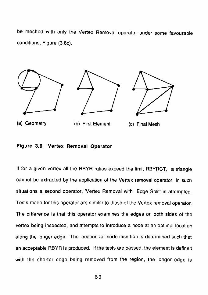
be meshed with only the Vertex Removal operator under some favourable
conditions, Figure (3.8c).
(a) Geometry (b) First Element (c) Final Mesh
Figure 3.8 Vertex Removal Operator
If for a given vertex all the RBYR ratios exceed the limit RBYRCT, a triangle
cannot be extracted by the application of the Vertex removal operator. In such
situations a second operator, 'Vertex Removal with EdgeSplit'
is attempted.
Tests made for this operator are similar to those of the Vertex removal operator.
The difference is that this operator examines the edges on both sides of the
vertex being inspected, and attempts to introduce a node at an optimal location
along the longer edge. The location for node insertion is determined such that
an acceptable RBYR is produced. If the tests are passed, the element is defined
with the shorter edge being removed from the region, the longer edge is
69

redefined as being connected to the new vertex and the uncommon vertex. The
triangle is formed by joining the vertex of the shorter edge and the new vertex
on the larger edge, shown in Figure (3.9a). The process of meshing a geometry
by the described operators is shown in Figure (3.9). Since the minimum RBYR
for all vertices is higher than the given RBYRCT, the vertex 2, required the
splitting of edge 1-2 into edges 1-9 and 9-2 shown in Figure (3.9a). Both the
operators continued to be applied to produce a mesh shown in Figure (3.9b). At
this point the removal of vertex 3 requires the splitting of edge 3-8 which is the
side of existing element 3-8-9. This edge can be split if element 3-8-9 can be
split into two elements as the edge is split. This operation is allowed as long as
the resulting elements have RBYR values less than RBYRCT,shown in Figure
(3.9c). Figure (3.9d) shows the final mesh.
5 4 3 _2
^q8
a) first edge split b) mesh before removing vertex 3
c) mesh after removing vertex 3d) final mesh
Figure 3.9 Vertex Removal with EdgeSplit
70

Situations arise when neither of the vertex removal operators can be applied.
In these cases, a third operator, 'EdgeRemoval'
is applied. This operator is
applied to an edge, when two angles subtended by other edges at the current
edge, are higher than the upper angle limit decided by the RBYR ratio. The
application of the Edge Removal operator introduces a new node inside the
domain being meshed. If all the above conditions are satisfied, Edge Removal
is applied by forming a triangle with the inserted vertex and the edge. Two new
edges and one new vertex is introduced in the region definition.
Consider the meshing of a hexagon with an RBYRCT ratio of 2.1. Because of
the low value of RBYRCT ratio, neither vertex removal operator can be applied.
Edge Removal is applied at the edge connecting nodes 1 and 2 and a new
node 7 is generated, see Figure (3.10a). Once node 7 is generated, Vertex
Removal can be applied, producing the mesh shown in Figure (3.10b).
5" '
65* '
6
a) removal of edge 1 -2 b) final mesh
Figure 3.10 Edge Removal Operator
71

3.3.2 HIERACHICAL DECOMPOSITION ALGORITHMS [25] [26] [27]
These algorithms are based on quadtree/octree decomposition of an object .
The idea underlying this recursive spatial subdivision scheme is to approximate
the object to be meshed with a union of disjoint, variably sized rectangles in two
dimensions or blocks in three dimensions. Ml These rectangles are generated
by subdividing recursively a spatial region enclosing the object, rather than the
object itself. Figure (3.11) provides a two dimensional example. The object, a
bracket with a hole, 'is boxed', to establish a convenient minimal spatial region.
The box is then decomposed into quadrants. When a quadrant can be
classified as wholly inside or outside the object, the subdivision ceases; when
the quadrant cannot be classified, it is subdivided into quadrants and this
process continues until some minimal resolution level is reached.
Approximations produced in this manner can be represented by logical trees
whose nodes have four sons, shown in Figure (3.12). Hence the name
quadtree. The tree structures in Figure (3.11) result from the subdivision rule
used to produce the decomposition. The tree structure can be thought of as
organizing or cataloging structure for data describing particular regions of
space, Figure (3.13a). Pertinent information that might be stored in such a data
record for automatic mesh generation are shown in Figure (3.13b). The record
includes classification of the spatial region represented by the node as inside,
72

^/// '/,//?f /tfr//'/y// '/ N:
11
'ss/// //y
object
23 I = inside cells
5
2
6- 0= outside cells
! 1 B= boundary cells
Figure 3.11 Hierarchical Approximation of an Object
Cm u1 vI)
figure 3.12 Tree Structure of Quadtree Approximation
73

data
-^record
I data j I data "j f~dwecord L record L^
data
record
Figure 3.13a Tree Structure of Data Records
data
Lrecord
. i i_
i i
i i.
i r n o Vr i i
1-
r- -
r
(a) (b) (c) (d) (e) (f)
CELL VERTEX EDGE ELEMENT NODE Properties :
I, O, NIO 1, O, ON 1, o X, Y, Z matl, load,
bS, biS constraints, {K},{D}
Figure 3.13b Hierarchical Structure for a Finite Element Model
74
outside, or on the boundary, shape functions for the finite element associated
with the region, and properties associated with the finite element, such as
stifness matrix, boundary conditions and such others.
At the lowest level of the tree are the smallest spatial regions and the simplest
finite elements. As one ascends the tree the regions become larger,
encompassing multiples of four elemental regions, and the finite elements
become superelements with associated"assembled"
stiffness matrices, and
collected constraints. Such an organization is ideally suited for mesh
refinement by subdivision.'Inside'
cells of the spatial decomposition can be
converted easily into finite elements or substructures, but'Boundary'
cells
require further processing to produce valid elements that closely approximate
the object's boundary.
The interior mesh is built with regular cells. This saves substantial
computational costs when deriving the stiffness matrix for the interior elements
and substructures, shown in Figure (3.11). The major disadvantage of this
method is the difficulty of identifying the boundary cells.
75

3.3.3 TRIANGULATION [28] [29]
Except for the heirarchical mesh generation technique, all the existing
techniques produce meshes composed of triangles and tetrahedra in two
dimensions and three dimensions respectively. For the topologicaly based
algorithms, the rules for element extraction are much more direct for simplex
topologies, triangles, tetrahedrons than for non-simplex ones, such as
quadrilateral or hexahedron. Spatial decomposition schemes as applied by
Yerry, l25l t28l reduce all elements to triangles or tetrahedra to accomodate
quatemal or octal cells. Yerry avoids ill-formed elements on the boundary, via a
smoothing operation that works best for simplex topologies.
For finite element analysis in two dimensions it is generally recognized that the
triangle can best adapt the boundaries of a domain. Very often only triangular
elements are able to fill domains with irregular boundaries and openings.
Triangular elements also allow a progressive change of element size without
serious distortions. Since most of the triangular elements situated in the interior
part of the domain have straight edges, explicit expressions of the elementary
stiffness matrices can be obtained without numerical integration. This gives
high computational efficiency. A comparision can be found between an
isoparametric eight node element and a linear strain six node element. I30!
76

Given a set of vertices (nodes) there exist many valid triangulations. Different
approaches have been used for finding a satisfactory triangulation. The
criterion forjudging triangulation algorithms are :
1 Speed- The algorithm should be quick, but more importantly, the time taken
should increase as slowly as possible as the number of points (n) increases.
2 Quality of triangulation. The shape of the triangles should as close to
equilateral as possible.
3 Generality. The algorithm should be capable of dealing efficiently with
complex geometry, including re-entrant boundaries and multiply connected
regions.
4 Extensibility. The algorithm should be capable of extension into higher
dimensions without violating any of the above criterion.
Over the years several techniques have been developed for triangulation of
planar surfaces. Some of them will be discussed, and finally the Delauny
Triangulation method, which is used in this thesis project will be discussed in
detail.
3.3.3.1 LEWIS AND ROBINSON METHOD [31]
This algorithm operates by applying a 'problemreduction'
technique to the
triangulation problem. The technique consists of dividing the original data
77

space into disjointed segments, and then solving the problem for each of these
smaller segments. The technique is applied recursively on each segment and
its sub-segments until each data space is sufficiently small for the application of
a very simple algorithm. The triangulation of region R of Figure (3.14) can
therefore be achieved by:
a) Splitting R into two sub-regions, R1 and R2, by creating a new boundary
across the region.
b) Solving the triangulation problems for R-| and R2 separately.
Usually, when a region has to be divided there are numerous possibilities. The
best of them is selected by the measure of a product called'
II '. The factors of
II are signed meaning positive or negative distances of the boundary points
from the proposed split line. II is formed by calculating two partial products,
one for each half of the split line as shown in Figure (3.15). Here two partial
products are Iii = did2 and n2 = S1S2, therefore, II = IIiII2. If,in forming the
partial products, one of the elements is opposite in sign to that of its
predecessor, then the split under consideration is rejected. All possible splits of
the region are not considered, since a boundary of n points would require 0(n2)
evaluations of product II. Examinations of splits is stopped when several valid
results have been computed. The splits between'
opposite'
boundary points
78

(c)
Figure 3.14 Subdivision of a Domain
roposed split
line
Figure 3.15 Information used for calculating II
79

are considered first as these are more likely to give high values of H From the
valid splits a choice is made for the split to be used. The selection is made for
the split which maximizes the expression :
n.Eb
where b is the number of boundary points and E is the minimum of
a) Half of the average distance between the boundary points, an
b) The distance from the split line of the nearest interior points contained
within any rectangle having the split line as the side.
The use of the above mentioned method tends to force the split to lie
perpendicular to, and cut in half, the line joining the two boundary points that lie
furthest apart. This eliminates the formation of elements with large aspect
ratios.
When a particular spilt of a region has been chosen any interior point which lies
close to the proposed split line is included as part of the new boundaries. This
gives the zigzag effect, shown in figure (3.14c). The inclusion of points is to
avoid the formation triangles with bad shapes. This is a very powerful and
efficient algorithm which can automatically triangulate multiply connected
regions, but its use is limited to two dimensions and axisymmetric shapes I31!.
80

3.3.3.2 TRIQUAMESH ALGORITHM [32]
'TRIQUAMESH'
is a technique for generating finite elements on arbitrarily
shaped curves, areas and volumes. It is currently used with SDRC's'l-DEAS'
geometric modeling program and'Supertab'
finite element pre/post processing
program.
This technique requires :
1 . Boundary file of the geometry.
2. Mesh density values at various locations in the geometry.
The algorithm creates nodes on the boundaries based on element densities.
This results in a polygon, each vertex of which is a node. This polygon is spilt
into two by generating nodes along the "best splittingline"
(discussed later).
This results in two sub-polygons. The process is continued until all polygons
are reduced to trivially simple polygons, which are triangles. These are the
finite elements. The nodes are then repositioned to give a smoother mesh.
A surface with a hole can also be reduced to a polygon by introducing cuts.
Figure (3.16a) shows a surface with two holes reduced to a polygon by
introducing two cuts. The surface is then transformed to a plane and nodes are
generated on the boundaries according to user defined densities. The nodes
are joined to form a polygon. The polygon is split into two parts in such a way
81

^>-o
(a)
invisible
region
(b)
(c) (d)
Figure 3.16 Triangulation by Triquamesh Technique
82

that the triangular elements formed have good triangular shapes.
The rules for spliting the polygon are as follows :
1. Split line, or the line dividing the polygon, should first be created through
concave vertices in the polygon. The other vertices should be considered
only if there are no concavities.
2. The split line should make angles as close as possible, to angles of 60 and
120 degrees with the boundary.
3. The split line should have the smallest possible length.
4. When creating nodes on the split line, based on the element density in this
region, the line should have minimum number of nodes to satisfy the
density criteria.
For every division there is more than one split line. Weighting or priority factors
for each of the rules 1 to 4 are determined. They are used to select the
optimum spilt line from among all the available lines. If the polygon has
concavity, then only some of the split lines are valid. This is because some of
them may not be wholly contained in the polygon.
The valid split lines are determined by creating a plot of visible points from a
given starting vertex P on the polygon, shown in Figure (3.16b). The angle'a'
from P to any location K on the polygon is plotted against 's', the length of the
83

polygon from P to K. If the polygon is convex then the plot keeps rising. In case
of concavities, the plot dips at such places, and the invisible areas ( any vertex
in these areas cannot form a split line ), in the polygon are determined shown in
Figure (3.1 6d). The process of splitting continues till one of the following
conditions occur :
1 . The polygon has only 3 vertices.
2. A polygon with a sharp angle is encountered. An angle of less than 80
degrees is a sharp angle. In this case, creating a split line through this
vertex will at best yield an element with a 40 degree angle, which is
considered poor. This possibility is ruled out. Then the split line has to
pass through two neighboring vertices, one on each side. The split line is
created without further search. This generates an element and at the same
time reduces the number of vertices in the polygon by 1, shown in Figure
(3.16c)
3.The remaining polygon is split using the method described earlier.
This technique is computationaly inefficient in three dimensions.
3.3.3.3 LO'S METHOD [33]
This mesh generation scheme can generate a triangular mesh within any
simply or multiply connected planar domain. It can also mesh regions with
84

holes. The mesh generation time is independent of the topology and geometry
of the given domain, but depends on the number of elements to be generated
and the number of nodes present.
The boundary of the domain is represented by a disjoint union of simple closed
loops of straight line segments. For simply connected regions there is only one
loop, whereas for multi-connected regions there may be as many internal loops
as the number of openings inside the domain.
The node numbering on the exterior boundary is generated in counterclockwise
order while the node numbering on the interior boundary or holes is generated
in clockwise order. More than one connected regions can be meshed. It is not
necessary to follow any sequence of boundaries while generating nodes on
them. This flexibility allows one to generate a triangular element mesh from one
region to another without concern for the common boundaries between them.
The algorithm first generates additional interior nodes according to the average
nodal spacing of all boundary segments which make up the region to be
triangulated. The program then connects all the nodes to form triangular
elements with good aspect ratios. The triangulation scheme is discussed as
follows :
85

The triangulation is designed to produce elements as near to equilateral
triangles as the set of nodes permits. The complete set of boundary nodes is
called generation front IX and the set of all interior nodes is defined as Q.
When a scheme of counterclockwise order or numbering is assigned to the
nodes on the exterior boundary and clockwise order assigned to the nodes on
the interior boundaries, then the domain to be triangulated has an interior area
always situated to the left of all connecting straight lines. This process has to
take place between two consecutive boundary nodes in belonging to II, as
shown in Figure (3.17). In the begining of the triangulation the generation front
II is equal to the collection of the domain boundaries. While the given domain
boundary always remains the same, the generation front changes throughout
the process of triangulation, and has to be updated whenever a new triangle is
formed.
The triangulation starts by selecting the last segment AB C II, shown in Figure
(3.17). The goal is to determine a node C c II u Q, such that it lies to the left of
directed line segment AB and ABC is in some sense optimal. Every time a node
from either II or Q is used for triangulation the respective set is updated. Both
the sets II and ft change continuously during the triangulation, and both are
reduced to zero at the end, indicating the termination of the process.
86

A check to see if triangle ABC overlaps any previously generated triangles or
any fixed boundary segments is unnecessary. This advantage not only gains
great deal of computer time but also produces elements with good aspect ratios.
This algorithm cannot be extended to mesh solids in three-dimensions.
N\N\N\M
Boundary to be triangulated Intermediate stage of triangulation
Figure 3.17 Triangulation by Lo's Method
3.3.3.4 SADEK'S ALGORITHM I34]
Given a domain of Figure (3.18a), with a number of nodes around its boundary
the most well conditioned elements or triangles which can be formed at each
corner of the domain are determined, shown in Figure (3.18b) . A corner is a
boundary point at which the boundary angle 0, is not equal to 180 , shown in
Figure (3.19a) Having computed this step, the elements formed are considered
cut out from the original area and the same concept is applied to the remaining.
87

I I area to be subdivided
Hi] area cut out before thenext cycle of subdivision
1,^s
1 ^V-
Figure 3.18 Stages of Element Generation in Sadek's Method
88

(a)
(c)
(d) (e) Generated
elements
Figure 3.19 Generation of a Node by Sadek's Method
89

The nodes around the original boundary of the domain are of level unity.
Subdivision at a corner node of level unity generates nodes of level two. Figure
(3.18b) to Figure (3.1 8e) show some steps of subdivision, and the levels of the
different nodes of the domain.
The subdivision of a domain is performed in succesive stages. In each stage a
continuous boundary layer is cut out. Elements cut out to form level two belong
to first boundary layer. The first stage is complete when all nodes bounding the
area to be subdivided reach level two, shown in Figure (3.18e). In case of a
domain with a number of inside holes, the nodes around the boundary of the
domain and those around the boundaries of the holes are all considered of
level unity. Subdivision is performed once by cutting a boundary layer around
the outer boundary of the domain and once by cutting a boundary layer around
the boundary of each hole.
The node generation procedure can be understood by considering the
geometry of Figure (3.19a). The number of triangular elements that can be
generated at a node'
i'
with an internal boundary angle 0j is taken as nearest
integer of 0j/(tc/3). The parameter 0j/(rc/3) is used to ensure that a suitable
number of triangles are generated and each of them is as equilateral as
90

possible. Assume that the angle 03 at node 3 is such that two triangular
elements can be generated. Well conditioned triangles will be produced if the
ratio a/b is equal to b/c. In other words length b is (ac)0-5. Therefore, length b
taken along the angular bisector of 03 is the position A-|(
of new node, shown
in Figure (3.19b). This is the position of the newly generated node if the
situation at node 3 is only taken into consideration. But the position of the new
node will influence the shape of the elements formed at adjacent nodes, namely
nodes 2 and 4. The procedure is repeated to find out the number of triangles
and the new node position. The angle 02 at node 2 is 180, thus three
triangles can be formed at equal divisions of 60, shown in Figure (3.19c). The
condition that makes the three triangles well conditioned is
d/e = f/g = g/a
or
e= (d2a)1-5 and g =(da2)1-5
The length g determines another position A2. This is the position of the new
node if the situation only at node 2 is taken into consideration. The situation at
node 4 indicates a third position A3 (see figure 3.1 9d), with lengths
h = (j2k)1-5 and l = (jk2)1-5
91

The best position is determined from A-| , A2 and A3 by finding the centroid of
the triangle formed by them
This algorithm gives elements with good shapes, but has no extension in three-
dimensions.
3.3.3.5 BYKAT'S METHOD [35]
The algorithm is a recursive shape controlling the triangulation method. The
method produces a node numbering which implies reduced bandwidth in the
matrix assembly of the solution equations. This approach saves a substantial
amount of time usually spent on renumbering nodes. The suggested data
structure allows simple implementation of a nested dissection algorithm for an
irregular simply- connected domain. The algorithm can be applied to polygonal
regions of any shape provided they are convex. If the regions are non-convex,
they are subdivided into convex shapes. This algorithm does not support
extension in three-dimensions.
3.4 DELAUNY TRIANGULATION
In this thesis, Delauny triangulation (DT) has been chosen as the method for
automatic meshing. Delauny triangulation can mesh surfaces in two-
dimensions and can be extended to three dimensions t36!. To understand the
92

method of construction of DT it is necessary to understand the definitions of the
terms'
tessellations'
and'
convex hull '. They are explained as follows :
Tessellations of a Plane
Subdivision of a plane into smaller regions is known as Tessellation of the
region. The region to be divided, and the subdivisions, can be of any polygonal
shape. The bold line of Figure (3.20) is the region to be subdivided and the
light lines are various Tessellations. Dirichlet has done useful work in
Tessellations f36!. In the rest of the text, Dirichlet Tessellations will be referred
to as DIT. Delauny worked further on DIT to show that a non -triangular
Tessellation of a convex hull can be triangulated. The DT can only triangulate a
convex region.
Region for Tessellation
Tessellations
Figure 3.20 Tessellations of a Plane
93

Delauny triangulation is the dual of the Dirichlet Tessellation construct. Given
the data for either the triangulation or tesselation, the unknown can be
computed. The DIT construct has been known to mathematicians for 130 years
and has been implemented in geography, geology, crystallography and other
fields. In the early 1980's Cavendish, David Field, Frey [291 and group, started
the development of a pre-processor by Delauny triangulation, from a CAD
database. DT is ideally suited to finite element applications because a mesh
can be created or modified dynamically, one node at a time. Each node
operation produces only a local change in the mesh. DT can generate
triangular elements that are'
best'
shaped for the given set of nodes.
Convex Hull [37]
Let S be a set of points and Ed be a'd'
dimensional space. The 'convexhull'
of
a set of points S in Ed is the boundary of the smallest convex domain in Ed
containing S. In two dimensional space E2 (d=2), a polygon is defined by a
finite set of segments such that every segment extreme is shared by exactly two
edges and no subset of edges has the same property, shown in Figure (3.21).
The segments are the edges and their extremes are the vertices of the polygon.
The number of vertices and edges are identical. A'n-vertex'
polygon is called
an 'n-gon'.
94

segments V""---^ ^--* #^convex hull of a
set of points
vertices
Figure 3.21 Convex Hull of a Set of Points
3.4.1 NEAREST NEIGHBOR SEARCH BY LOCI PROXIMITY [37]
Given a set S of N points in a plane. Let the universal set be U, then the set
M = U nS. For any two points p; and pj of the set S, the set of points in the set
M, closer to pj than to pj is the half plane including pj. This half plane is
defined by the perpendicular bisector of the vector p, pj, shown in Figure
(3.22a). Let us denote the half plane between the points pj and pj by H(p,-,pj).
A point pj is the nearest neighbor of a subset of set M if no other point Pk
belonging to the set S lies in the half plane H(pjPj). The locus of points closer
to pj than any other point of the set S, which we denote by V(i), is the
intersection of N -1 half planes, and is a convex polygonal region having no
more than N -1 sides, shown in Figure (3.22a). Mathematically, the locus is
defined as :
95

v co = n h ^i' pi) (17)
#\
The half -planes partition the plane into convex polygons known as Dirichlet,
Thiessen, or Voronoi polygons I38!,shown in Figure (3.22b). From now on, the
given points in the set S, will be called nodes. Dirichelet tessellations assign to
any point in the plane a subdivision containing a node which is its nearest
neighbor. The point of intersection of the half-planes is called the vertex of DIT,
shown in Figure (3.22b).
. half plane for p. p
y i j
\
Figure3.22a Half Planes and Locus of Intersection of Half Planes
half planes
Figure 3.22b Vertices and Half Planes of Dirichlet Tessellations
96

The light lines in Figure (3.23) outline the half-planes induced by a set of 16
nodes. The intersections of these half-planes form the Dirichlet tessellation of
the entire plane. If all the node pairs which have common half planes, are
joined by edges, the result is the Delauny triangulation of the convex
hull of the nodes, shown as dark lines in Figure (3.23). Node pairs joined by
lines in the triangulation are contiguous. The dual existence of the two
geometric constructs is obvious from the Figure (3.23). There is
correspondence between the points (vertices, nodes) of one, and the
subdivisions (tessellation, triangles) of the other. Given a set of nodes, and
either tessellation, it is straight forward to compute the other. To date, most
computation methods have focussed on the Dirichlet tessellation , however, as
Watson t39!, has emphasized, the DT is easier to compute in two dimensions,
and in three dimensions the method has an analogical extension.
dirichlet tesselation
delauny triangulation
Figure 3.23 Delauny Triangulation with Dirichlet Tesselation
97

3.4.2 PROPERTIES OF DELAUNY TRIANGULATION
The properties of Delauny triangulation which make it a efficient algorithm are
presented below :
3.4.2.1 OPTIMAL EQUIANGULARITY PROPERTY
A set S, of nodes may be triangulated in different ways. Figure (3.24) contrasts
DT with another possible triangulation of the same set of nodes. In finite
element applications it is desirable to have a triangulation which maximizes the
equiangularity of the triangles where all the angles are as close to being equal
as possible. Equiangularity of the triangles leads to finite elements with an
aspect ratio close to unity. It has been shown that of all the possible
triangulations of a given set of nodes, the Delauny triangulation forms triangles
which are as equiangular as can be achieved I40l. This is called the optimal
equiangularity property.
Figure 3.24 Delauny Triangulation and General Triangulation
98

3.4.2.2 EMPTY CIRCUMCIRCLE PROPERTY
Let a vertex of the Diriichlet tessellation be v. Assuming that no four nodes of
the original set of nodes S, lie on a circle, it can be proved that :
For every vertex v of the Dirichlet tessellation of the set S, the circle C(v)
contains no other nodes of the set shown in Figure (3.25), or in other words
every vertex of the Dirichlet tessellation is the common intersection of exactly
three half planes I37!.
_ _ Delauny triangle
-^ Half planes
p arbitrary point
Figure 3.25 Empty Circumcircle of a Delauny Triangle
The vertex v is associated with a given Delauny triangle, namely, the triangle
constructed from the nodes whose half-planes come together at that vertex.
The three half planes of the Dirichlet tessellation which intersect at the vertex v
are the perpendicular bisectors of the sides of the Delauny triangle. Therefore,
the vertex is at the circumcenter of the DT, p-| p2 p3 The vertex is also
equidistant from all three nodes of the triangle. Furthermore, since p1f p2, and
99

p3i are the three nodes of the set S, if the circumcircle C(v) contains some other
node, say p4, then p4 is included in the half plane H( p3 , p-|) . By definition of
Dirichlet tessellation this is a contradiction. Therefore, in Delauny triangulation
there is no node in the open circumdisk, the interior of the circumcircle of any
triangle. This is a general property of a DT, and provides the basis of a
convenient and efficient method of construction. The empty circumdisk also has
an analogue in three dimensions and has been described by Watson. I41!
Figure (3.26) shows the circumcircles associated with a set S. It was assumed
that only three nodes of the set S can lie on a circumcircle. The case where
more than three nodes lie on the circumcircle is discussed in the following
section.
Figure 3.26 Empty Circumdisks of a Set of Nodes
100

3.4.3 DEGENRACIES OF REGULAR DELAUNY TRIANGULATIONS
When four or more nodes lie on the same circle, degenracy occurs, and the
empty circumdisk property leads to no unique DT triangulation.
Figure 3.27 Degeneracy of Delauny Triangulation
The degenrate situation can be understood by studying Figure (3.27) above.
The left side of the figure shows a normal Delauny triangulation of nodes ABCD
(dark lines). The corresponding DIT are shown by light lines. The circumcircle
associated with the nodes ABC is also shown. The node D lies outside the
circumcircle. The DIT has two distinct vertices, each of which is the intersection
of the three half planes. The right hand side figure is a DIT with two distinct
vertices, but their contiguities are different from the case on the left.
Consequently the Delauny triangulation is different. In both cases the DT is
unique. In the quadilateral ABCD the placement of the fourth node relative to
the circumcircle determines which of the two possible diagonal connections can
101

be made to form the DT. In the center figure, the fourth node lies precisely on
the circle. Here the two vertices coalace into a single degenerate vertex which
is the intersection of the boundary segments and the corners of the four half
planes. The Dirichlet Tesselation is still well defined but the DT is not unique as
the triangulation can be done by joining any of the two diagonals. The choice is
made by determining which diagonal generates'good'
set of triangles.
Degenracies can occur in a large set of nodes whenever a localized cluster of
nodes lie on a common circle. In such cases DT is done by breaking down the
existing polygon.
In general, the number of boundary segments of the DIT which intersect at a
given vertex is equal to the number of nodes which lie on the circle. The
degenerate Delauny tesselation is the polygon formed by connecting the nodes
in order around the circle.
3.4.4 DELAUNY TRIANGULATION ALGORITHMS
Classical algorithms for constructing Delauny triangles or, equivalent^, its dual
graph DIT can be classified into :
Incremental Algorithms f41! I42! t43l These algorithms construct the tessellation
by starting from any interior node or from the boundary of the domain, and
102

stepwise add the remaining nodes of the given data set to the subdivision.
Divide and Conquer Algorithms [31] [44] These algorithms recursively split the
set of the data points into equally sized subsets until elementary subsets are
obtained, and then merge the resulting tessellations piecewise.
These algorithms can be further classified into one-step or two-step methods
depending on whether they produce the final optimal triangulation in single
step, or they build an arbitrary triangulation first, and then modify it by an
iterative application of an optimization criterion.
Another approach to the construction of DT consists of a two step process. First,
Dirichlet tessellation of the given data set is carried by employing either the
divide and conquer or incremental approach. Secondly, the Delauny
triangulation of the DIT is done. This scheme is space inefficient due to the
temporary data structure for the DIT. This structure contains more information
than needed to compute the triangulation.
The method selected in the present work is the dynamic incremental algorithm
known as Watson's algorithm. This method can triangulate only the convex
hull with no internal holes. In this thesis the algorithm is modified to work with
non convex shapes with or without holes. Watson's algorithm and the
modifications are discussed in chapter 4.
103

CHAPTER 4
AUTOMATIC MESH GENERATION
BY MODIFIED WATSON'S METHOD
A mesh generator is a Pre-processor with limitations. The Pre-processor has all
the functions required to prepare a finite element model for analysis as
discussed in Chapter 1. A mesh generator can only discretize the geometric
model into finite elements. It does not have the capabilities of modeling
boundary conditions and physical properties of the finite element mesh. In
Chapter 1 it was stated that the objective of this thesis is to develop an
automatic mesh generator. To achieve this goal extensive research was
conducted. The first three chapters reflect this research effort. To recapitulate
the contents of the previous chapters a brief outline is given below.
Chapter 1 reviews the history and functions of Pre-processors.
Chapter 2 reviews geometric modeling and the geometric modeling methods.
Chapter 3 reviews the existing automatic mesh generation methods.
Watson's algorithm for Delauny triangulation can mesh the 'convexhull'
of a
given set of nodes. It cannot mesh non-convex surfaces or surfaces with holes.
This algorithm has been modified to mesh convex and non-convex surfaces in
two dimensions. The modified algorithm can also mesh surfaces with or without
104

holes. The mesh generator developed in this thesis can create triangular
elements which have acceptable shapes as finite elements. Since the finite
elements created by the algorithm in this thesis are triangular in shape, the
terms'triangle'
and'element'
are synonymous.
To mesh a geometry, first the nodes have to be generated on and inside the
geometry boundaries. These nodes are then combined to give elements. The
possibility of generating good elements is dependent on the placement of
nodes. A node generation algorithm has been written which can give nodes for
potentialy well shaped elements. The modified Watson's algorithm then
generates a mesh from the set of nodes. The density of the elements is
controlled by a density parameter in the node generation algorithm. In this
chapter first the node generation algorithm is presented, followed by Watson's
Delauny triangulation algorithm and the modifications applied to it. Finally,
some results and conclusions are presented.
4.1 NODE GENERATION
The following steps provide a discription of the pseudo code for the generation
of boundary and interior nodes on and in a given domain, shown in Figure (4.1).
1. Sort out ymjn and ymax of the domain.
2. Imaginary horizontal lines at a distance ymax- mD are drawn between ymjn
105

and ymax across the domain. Here'D'
is the element'spacing'
or density
parameter specified by the user. The parameter m is defined by
m = 0, n by 1
where n is an integer defined by
let
n = (Ymax" yminVD
Yl = Ymax- mD
O Line segments
X Intersections
Y = mD
Figure 4.1 Node Generation
3. Determine the intersections of each horizontal line with the region. Let S
{PjQj ,i = 1,N} be the set of line segments representing the region
boundaries. The intersection points between each horizontal line and the
region are determined by considering the line segments of the set S one by
106

one. As an example consider line segment P-|Q-| of Figure (4.1). Let X =
X (P-|), Y-| = Y(P-i), and X2 = X(Q1) , Y2 = Y(Q-|). There is intersection only if
(i) (Yi- YL) (Y2
-
YL) < 0
or,
(ii) (Y!-
YL) (Y2- YL) = 0 and (YL > Y, or YL > Y2)
4. Each horizontal line must cut the domain in an even number of points, and
the intersection points are arranged in ascending magnitude of X.
5. Assume there are 2n cuts between a particular horizontal line and the
segment set S. The cuts are considered two by two, begining with the first
and second cuts. No nodes are placed at the intersections, interior nodes
are generated between each pair of cuts by placing them a distance D from
each other.
6. After the first two cuts, the process is continued with the third and the fourth
cut, till 2n-1th and 2ntn cuts. Steps 1-6 are repeated for all horizontol lines.
7. Boundary nodes are generated by placing them at and between vertices of
each line segment of the set S. The spacing for boundary nodes can be
user defined or taken as D by default.
To avoid triangular elements with small interior angles, a check is made
107

while generating boundary nodes to see if an interior node is less than :
(X-Pj)2+ (Y-Qj)2
<C2
where (X,Y) is the node to be generated, (Pj , Qj ) is an interior node, and C
is a constant dependent on the average element size D of the interior
region. In this algorithm C = 0.7 D. If there is an interior node closer than the
above criteria, it is deleted in preferance to the boundary node. This insures
that no interior node is too close to the boundary to give an element small
interior angles.
4.2 WATSON'S DELAUNY TRIANGULATION ALGORITHM
First, Watson's algorithm for creating Delauny triangles is presented. Then the
advantages and disadvantages of this algorithm are discussed followed by the
modifications to overcome the disadvantages. For a given set of nodes the
following steps are carried out :
Stepl Create a triangle which encloses all the given nodes, see Figure
(4.2). This triangle is called the 'enclosing triangle'. In this thesis the
enclosing triangle is created by bounding the set of nodes by a
rectangular box. The vertices of the box are at a relatively large
distance from the extreme nodes. The mid point of the top side is
joined to the ends of the bottom side to form the enclosing triangle.
108

enclosing triangle
Figure 4.2 The Enclosing Triangle of Nodes
Step2 Construct the Delauny triangulation of the vertices of the enclosing
triangle and one of the boundary nodes, shown in Figure (4.3).
Maintain a master list of the triangles and their circumdisks
(circumdisks are explained in section 3.4.2.2). The circumcenter and
circumradii of each circumdisk is calculated and stored with the
master list.
109

Figure 4.3 Delauny Triangulation of a Node
Step3 Insert the rest of the boundary nodes into the triangulation one at a
time as follows:
a) Determine which existing circumdisks contain the given node.
This is done by comparing the circumradius of each circumcircle
with the distance between the node to be inserted and the
circumcenter of that circumcircle, as shown in Figure 4.4.
b) Create a list of triangles associated with the circumcircles
determined in step 3a. The union of these triangles is called the
'insertion polygon', see Figure (4.5).
110

new node for insertion
circumcircles
containing
the new node
circumcenters
Figure 4.4 A Node for Insertion and Empty Circumcircles
insertion polygon
Figure 4.5 The Insertion Polygon
c) Create a list of boundary edges of the insertion polygon.
d) Create new triangles filling the insertion polygon by connecting
the new node to the boundary vertices of the insertion polygon.
e) Delete from the master list the triangles and the circumdisks
determined in step 3a and step 3b, see figure 4.6.
f) Add to the master list all triangles and their associated
circumdisks created in step 3d.
111

__ New Triangles
Old Triangles
Deleted Edge
Figure 4.6 New Triangulation
Step 4 Repeat step 3 with the remaining boundary nodes followed by the
interior nodes.
Step5 Remove from the master list all triangles which share a vertex with the
'enclosing triangle'. The union of the remaining triangles in the
master list is the Delauny triangulation of the convex hull of the nodes.
Watson's algorithm cannot triangulate a non-convex surface and a surface with
holes, shown in Figure (4.7). The order of compute time for a two dimensional
mesh is O(nlogn), where n is the number of nodes.The algorithm triangulates
the convex hull of the nodes. As seen in Figure (4.8), this algorithm cannot
identify which of the Delauny triangles are not part of the geometry. In Figure
(4.8) triangles land 2 are inside the hole and triangle 3 is outside the
112

geometry. Therefore, all three are 'external triangles'. Triangles lying entirely
outside the geometry or inside the holes are external triangles. A modification
is done on this algorithm in order to identify external triangles to and discard
them. The modified algorithm can triangulate geometries with irregular shapes
and with holes.
Figure 4.7 A Non-Convex Geometry with Hole
nodes
Delauny triangles
External triangles
Figure 4.8 Delauny Triangulation by Watson's method
113

4.3 MODIFICATIONS OF WATSON'S ALGORITHM
Delauny triangulation of the geometry by Watson's method is carried out first.
After the convex hull of the set of nodes is meshed or triangulated, 'external
triangles'
are identified and removed by application of a simple procedure.
Consider a polygon P made up of line segments, shown in Figure 4.9. Whether
a point'z'
is external or internal to the polygon P can be cheked as follows:
(a) Location of a point in a polygon (b) Placement of point z in a triangle
Figure 4.9 Identifying External Triangles
Let a horizontol line L pass through the point z. If L does not intersect P, then
z is external. Assume that L intersects P and consider that L does not intersect
any vertex of P. Let M be the number of intersections of L with the segments of
P to the left (or right) of z. Since P is a closed or bounded polygon, the left
114

extremity of L lies in the exterior of P. Consider moving right on L from -
oo,
towards z . At the left most crossing with the boundary of P, one moves into the
interior. At the next crossing one is outside. Therefore, z is internal only if M is
odd and vice-versa. The pseudo code of the algorithm is as follows :
begin M : = 0 ;
for i : = 1 until N do if edge (i) is not horizontal then
if ( lower extreme of edge (i) intersects L to the left of z )
then M:= M + 1;
if ( M is odd ) then z is internal else z is external
end.
In the modified algorithm of this thesis the polygons are the external and
internal boundaries of the geometry. Triangular elements associated with the
external and internal boundaries are saved in two seperate lists. The z point of
each triangular element is located at the mid-point of the line joining the
mid-points of any two sides, as shown in Figure (4.9b). Elements associated
with the external boundary are checked to determine if they lie outside the
geometry, and discarded. Elements associated with the internal boundaries are
checked to determine if they lie inside the geometry, and discarded.
115

4.4 RESULTS
In the automatic mesh generator developed in this thesis the node density and
consequently the element density are defined by the parameter'D'
explained in
section 4.1 of this chapter. This parameter'D'
is called 'spacingparameter'
in
the algorithm. The spacing parameter has a range between 0 and 100. A
default value of 35 is given to'D'
in the node generation algorithm. The user
has the option of changing the default value while generating boundary nodes
and interior nodes. Some results of the modified Watson's Delauny
triangulation method are presented now.
A square with nodes at the corners is shown in Figure (4.10a). This is a case
where four nodes lie on a circumcircle. The geometry is meshed with elements
1 and 2 by connecting nodes 2 and 4. Nodes 1 and 3 can also be connected to
form a valid mesh, shown in Figure (4.10c). There is no unique Delauny
triangulation, as was discussed in chapter 3. The fourth node on the
circumcircle is known as the degenerate node. The modified algorithm in this
thesis is biased to consider the degenerate node as Inside'. The fourth node is
inside the circumcircle as shown in Figure (4.10b). The mesh is generated by
connecting nodes 2 and 4. The fourth node is'outside'
the circumcircle in
Figure (4.10c). Therefore, the mesh is formed by connecting nodes 1 and 3.
116

Delauny triangulation of a 'convexhull'
of a set of nodes is shown in Figure
(4.11). The circumcircles associated with the Delauny triangles of Figure
(4.11a) are shown in Figure (4.11b). Each circumcircle is 'empty'. The 'cross
hair*
show the circumcenters of these circumcircles.
Figure ^.10 Delauny Triangulation of a Square
Figure 4-.11 Triangulation of a 'ConvexHull'
117

A geometry with concavities is shown in Figure (4.12a). Boundary nodes and
interior nodes are generated with the default spacing parameter 'D', shown in
Figure (4.12b). The mesh of the set of nodes is generated by 'createmesh'
command in the program. The corresponding mesh is shown in Figure (4.13a).
Undesired nodes can be deleted before the mesh generation is carried out.
The algorithm also has the flexibility of deleting interior nodes after the mesh
generation. The high-lighted node of Figure (4.13a) is deleted after the mesh is
generated. Re-meshing is done in the local region of the deleted node, shown
in Figure (4.13b). A node can be added in the interior of the geometry after the
mesh generation. The high lighted node of Figure (4.13c) is added to the set of
nodes of Figure (4.13b). For deleting or adding a node after mesh generation
the re-meshing algorithm finds the 'insertionpolygon'
without a node or with the
new node as the case may be and creates a new set of triangles. The insertion
polygon is explained in section 4.2 of this chapter. This feature of deleting and
adding nodes after mesh generation provides the user the control over the final
set of finite elements. The algorithm is time and cost efficient. It re-meshes a
small set of local elements without disturbing the entire mesh, which can have a
large set of elements.
A high density of a set of nodes and their triangulation are shown in Figure
(4. 1 4a) and Figure (4. 1 4b) respectively.
118

(a)
(b)
Figure ^.12 Node Generation on an Irregular Boundary
119

node deleted
in b)
a) Automatic Mesh
b) Node Deleted
node added
in b)
c) Node added
Figure 4.13 Automatic Meshed and Remeshed Elements
120

o
o o o
o o o o o
o o o o o o
o
ooooooo
o oooooooooo
ooooooooooooooo
ooooooooooooooo
oooooooo o
o o
ooooooo0
OooOOOOO
o o o o o
o o o o
o o o o o
o o o
o o
o oo
a) Generated nodes
b) Generated mesh
Figure 4.14 High Node and Mesh Densities
121

The modified algorithm can mesh surfaces with holes. In this case the convex
hull of the geometry is meshed first, then the external triangles are identified
correctly by the 'delete externaltriangle'
algorithm discussed in section 4.3 of
this chapter. The external triangles are discarded from the master list of the
elements. An irregular geometry with a hole is meshed, shown in Figure (4.15).
This geometry was discussed in section 4.2 of this chapter. It was shown that
Watson's Delauny triangulation algorithm cannot identify the 'external triangles'.
The modified algorithm can mesh any irregular shape with or without holes. An
irregular geometry with four holes of different shapes is shown in Figure (4.16a).
The final mesh of the geometry is shown in Figure (4.16b).
Figure 4.15 Mesh of a Geometry with a Hole
122

Figure 4.16 An Irregular Geometry with Holes
Figure 4.17 Mesh of an Irregular Geometry with Holes
123

4.5 DISCUSSIONS
If during the triangulation a node lies precisely on the bounding polygon
boundary, a degenerate triangle is formed. All three nodes of this triangle will
be collinear. The collinearity can be detected during the calculation of
circumradii of the triangles. The circumradius of a degenerate triangle is zero.
Any triangle with collinear nodes is excluded from the master list of triangles.
A degeneracy can exist because of the limited arithmetic precision of the
computer. Due to round off errors, ambiguity can occur whenever a new node
is close enough to a circumcircle to be indistinguishable from one that lies
exactly on the circle. This can lead to situations which influence the
assessment of whether the node is inside, on, or outside a circumcircle.
Inconsistent decisions with respect to the triangles that are candidates for the
insertion polygon can result which will yield an insertion polygon that is not
connected. This will ultimately leave gaps or overlapping triangles. A practical
way to circumvent the degeneracy problem is to bias the in/out decision by a
amount slightly larger than the maximum possible truncation error. In the
developed algorithm a parameter 'diskspacing'
controls this error. For the
tested geometries the truncation error has not been encounterd.
124

4.6 CONCLUSIONS
This algorithm is a step towards creating a true automatic Pre-processor. Some
of the desired capabilities of an automatic pre-processor, that is, minimum user
interaction, mesh generation from the geomtric database, elements with good
aspect ratios, are all addressed in this program. Other desirable features, as
discussed in chapter 1,can be added in the future. The modular structure of the
algorithm provides access to programming additions and modifications. The
node generation algorithm can also be enhanced to add flexibility to the
program. For example, instead of generating nodes at a uniform spacing along
a segment, the algorithm can place nodes at a changing ratio of distances
between consecutive nodes. In this manner, density of elements within a region
can be varied. This is a desirable feature and provides for good approximation
in the region of interest, avoiding extra elements elsewhere. The algorithm can
also be modified to check the curvatures of curve segments. The programme
can then be modified to add extra nodes on curves.
Some popular and efficient algorithms for triangulating non-convex planar
surfaces were presented in chapter 3. These algorithms split a non-convex
surface with or without holes into a number of convex regions. Each algorithm
has a different criteria for determining the split regions. For an irregular
geometry with holes the spliting operation has to be performed more than once.
125

These operations require extra computer time for generating good meshes. In
the modified Watson's algorithm presented in this thesis, the 'delete external
triangle'
algorithm can be made more efficient. At the time of meshing the
convex hull of the nodes, triangles with one or more external boundary
segments as their sides can be saved in an'external'
list. Similarly, triangles
associated with the internal segments can be saved in an'internal'
list.
Triangles in the'external'
and'internal'
lists should be checked by the 'delete
externaltriangle'
algorithm. This new scheme of determining valid triangles
will save computer search time and enhance the algorithm of this thesis.
Delauny triangulation method is an efficient method for mesh generation in two
dimensions as well as three dimensions. A recent paper t45l has presented a
mesh generator which creates tetrahedrons in three dimensions through
Delauny triangulation method.
Expert systems were suggested in chapter one. Adding'intelligence'
to
Pre-processors will be beneficial to finite element analysts. Research in this
area indicates that various academic institutes as well as industrial research
centers are working towards adding intelligence to FEA.. Contemporary expert
systems in FEA are discussed in the following chapter. Proposals for integrating
Expert Systems with a Pre-processor are also presented.
126

CHAPTER 5
EXPERT SYSTEMS IN FINITE ELEMENT ANALYSIS
An analyst's interaction is essential even for automatic finite element
pre-processors. The automatic mesh generator developed in this thesis project
requires the user to decide on the density of elements. Curved areas and sharp
corners need more elements around them than straight edges. High density of
elements in the whole region can be expensive. One has to use knowledge
and experience to decide upon an optimum density.
This is one of the many occasions where the analyst's knowledge and
experience in finite element analysis is required to make a decision in
preparation of a finite element model. Expert Systems can relieve the analyst of
this burden and make finite element modeling less costly and less time
consuming. Expert Systems are part of the field of 'Artificial Intelligence'. In this
chapter Artificial Intelligence, Expert Systems, and their integration with finite
element analysis is discussed.
5.1 ARTIFICIAL INTELLIGENCE
Artificial intelligence (Al) is the study of methods by which computers are made
to perform intelligently, in an effort to mimic the human brain. The history of
127

Artificial Intelligence is about thirty years old. During these years significant
advances have been made in research laboratories and academic institutions,
in order to imitate the functions of the human mind. In the late 1970's the
computational power of computers advanced by leaps and bounds, and
commercial applications of Artificial Intelligence emerged. Modern engineers
and computer scientists are actively involved in the development of various
applications of Artificial Intelligence. The primary areas of research are :
1. Natural languages.
2. Vision systems.
3. Expert systems.
Expert Systems research can claim responsibility for the current heightened
awareness of Artificial Intelligence. Expert Systems are one of the first Artificial
Intelligence technologies to be used commercially and hold a tremendous
promise for the future.
5.2 EXPERT SYSTEMS I46l
An Expert System contains knowledge about a particular field and assists
human experts in providing specialized information to people who do not have
expertise in given field. Human experts in any field are frequently in great
demand and unsolved problems far exceed the number of human experts who
can solve them. Expert Systems are a solution to this dilemma.
128

Although both Expert Systems and database programs feature the retrieval of
stored information, the two types of programs differ greatly. Database programs
contain knowledge of their particular domains and areas of expertise. This
knowledge is declarative or factual and a database program cannot draw
conclusions by the rationalization of the facts within its domain. In contrast,
Expert Systems contain expertise consisting of both declarative and procedural
knowledge which allows them to emulate the reasoning process of the human
experts.
5.3 COMPONENTS OF AN EXPERT SYSTEM
Currently there are no standard Expert Systems. Because of a variety of
techniques used to create these systems, they differ as widely as the
programmers who develop them, and the innumerable problems they are
designed to solve. The principal components of most Expert Systems are as
shown in Figure (5.1). They are as follows :
1 . Knowledge Base
2. Inference Engine
3. User Interface
129

5.3.1 KNOWLEDGE BASE
The component of the Expert System that contains the system's knowledge is
called the knowledge base. A knowledge base contains both declarative
knowledge, facts about objects, events, and situations, and procedural
knowledge, consisting of information about courses of action. Depending on
the two forms of knowledge chosen, knowledge can be separate or integrated.
Although many knowledge representation schemes have been used in expert
systems, the most prevalent form is the 'rule based production system'. I46!
In a rule based system, the procedural knowledge, in the form of heuristic
"if-then"
is completely integrated with declarative knowledge. Not all rules
pertain to the system's domain. Some production rules called meta-rules
pertain to other production rules or even to themselves. A meta-rule is a "rule
about a rule". It helps in guiding the execution of an Expert System in
determining conditions under which it is considered.
5.3.2 INFERENCE ENGINE
Access to a great deal of knowledge does not make an expert. One must know
how and when to apply the appropriate knowledge. Similarly, having a
knowledge base does not make an expert system intelligent. The system must
have another component that directs the implementation of the knowledge.
130

That element of the system is known variously as the control structure, the rule
interpreter, or the Inference Engine.
The Inference Engine is the key to the workings of the entire system. It makes
high level decisions that were until now made by the expert. Ideally, it
possesses all the knowledge held by its human counterpart and is able to make
the same decisions, only faster. In reality it can possess only a small subset of
the knowledge of the human expert and is much less flexible. It still can,
perform many if not all, human tasks. When unable to reach a decision the
Inference Engine transfers control to the user.
An advantage of having an Inference Engine is that it provides a framework on
which a fully automated system can be built. It also creates a situation where
all quantifiable knowledge can be quickly entered into the system, leaving only
the undefinable intuition decisions for people. The Inference Engine processes
information in the form of value parameters. Parameters can be numerical
values, Booleans, strings, or taken from a list. They quantify what is known
about a goal and what needs to be decided. The value of the parameters are
determined through the value of other parameters and rules. Rules tell how to
determine new parameter values from existing values. The rules have two
parts, the predicate and the antecedant.
131

The predicate tells whether or not a rule is applicable in a given situation. The
antecedant is the action part of the rule. It tells what new information can be
deduced from the fact that a predicate was satisfied.
The Inference Engine uses two schemes for finding the sequence of
deductions. They are called forward chaining and backward chaining. In
forward chaining the Inference Engine scans the rule base for applicable rules,
whose predicate is satisfied by known information. When such rules are found
the new information contained in the rule antecedant is added to the pool of
knowledge. It is hoped that by continually increasing known facts, the desired
fact or goal will eventually be deduced.
Backward chaining works from facts that need inference and tries to find rules
whose antecedant will determine this fact. As such rules are found, their
predicates are checked for truth. If they are not satisfied, then the rules are
backward chained for determination. Eventually, it is hoped that all the
predicates of the rules needed to show result by a given scheme will be
satisfied by the facts that are known initially.
Although each method operating on its own is merely a blind search for a valid
chain of deductions, a combination of these methods gains advantages.
132

5.3.3 USER INTERFACE
The component of the expert system that communicates with the user is known
as the User Interface. The communication performed is bi-directional. At the
simplest level the user must be able to define the problem to the expert system,
and the system must be able to respond with its recommendations. There are
several other tasks performed by the User interface. The user may'question'
the system's decisions and ask for its 'reasoning'. The system may prompt the
user for more information.
Although the designers of expert systems have generally a great deal of
experience with computers, potential users of expert systems are frequently
novices. Therefore, it is important to ensure that an expert system is especially
easy to use. Most User Interfaces make use of techniques developed in the
natural language discipline of Artificial Intelligence. Natural language
techniques allow the user to communicate with the expert system in ordinary
English and enable the computer to respond in the same language. This type
of interface is sometimes called a natural language front end.
5.4 DEVELOPING AN EXPERT SYSTEM
There are two types of people involved in developing an expert system.
Knowledge engineers and domain experts.
133

Knowledge engineers are Artificial Intelligence specialists. A computer scientist
or a programmer who is skilled at developing expert systems can be a
knowledge engineer. A domain expert is an individual who has significant
expertise in the domain of the Expert System being developed. It is not critical
that the domain expert understand Artificial Intelligence or Expert Systems. It is
one of the functions of the knowledge engineer.
Typical development stages of an Expert System are as shown in Flow chart
(5.1)
Conceptualization Implementation
DeterminingThe
Characterstics
of the problem
Finding
Concepts
To Represent
The Knowledge
Desianina
Structures
To Organize
The Knowledge
Formulating
Rules that
Embody the
Knowledge
Validating
The Rules
Identification Formalization Testing
Flowchart 5.1 Development Stages of an Expert System
5.4.1 IDENTIFICATION
The domain expert describes several typical problem situations. The knowledge
engineer attempts to extract fundamental concepts from the case presented in
order to develop a more general idea of the purpose of the expert system.
134

Results are evaluated at each stage and the domain expert suggests
corrections.
5.4.2 CONCEPTUALIZATION
Once the problem is formally identified it is analyzed further to ensure that its
specific and general requirements are understood. The knowledge enginner
frequently creates a diagram of the problem to depict graphically the
relationships between the objects and the processes in the problem domain.
As in the identification stage, this stage also evolves iteratively.
5.4.3 FORMALIZATION
During this stage the problem is connected to its proposed solution, that is an
expert system. It analyzes the relationships depicted in the conceptualization
stage. The knowledge engineer begins to select the development techniques
that are appropriate to this particular system. The analyst becomes familiar
with :
1 . The various techniques of knowledge representation and heuristic search.
2. The Expert System"
tools"
that can expedite the development process.
3. Other Expert Systems that may solve similar problems .
If a rule based system is being developed, the knowledge engineer develops a
135

set of rules for review of domain experts. Rules are revised until there is full
agreement. To facilitate the formalization stage, Artificial Intelligence
researchers are looking for ways to achieve time-effectiveness in entering
information into the knowledge base.
5.4.4 IMPLEMENTATION
During the implementation stage, a prototype of the expert system is developed
to help the knowledge engineer determine if correct techniques were chosen.
Once the prototype has been refined sufficiently to allow it to be executed, the
system is ready to be tested thoroughly to ensure that it executes correctly.
5.4.5 TESTING
Testing is the last stage of the development process. Here the knowledge
engineer revises the structure and implementation of the expert system until the
system provides solutions as valid as those of a human expert.
5.5 EXPERT SYSTEMS IN FINITE ELEMENT ANALYSIS
Currently in finite element methods the finite element model is created on a
computer aided design (CAD) system. Then the finite element analysis is
carried out on the computer by a FEA code such as, Nastran, Ansys, etc. The
finite element model is generated interactively. Because of the time required
136

for the generation of the analysis model, "the analysis is used primarily for
verification rather than feedback, to facilitate iterative design improvement". I47]
"The reason for this bottleneck in the FEA process is the need for expertise in
the finite element model generation stage of theanalysis."
l47l Answers from a
FEA are only as good as the model itself, and a FEM model is as good as the
engineer's understanding of the physics of the problem. I48) If a young
engineer sets out to model a plate structure without understanding the
underlying mechanics of how the structure may behave, he may make incorrect
modeling decisions leading to an incorrect analysis and interpretation of the
results.
A second major stumbling block in automating the FEA process is the host of
commercially available packages to perform the analysis. Understanding the
myriad of details necessary to effectively use the tools of a given software
package is an art itself. According to Henry Fong I49!,"The name of the game
is confusion. The user needs help from the code developers to decide the
suitability of certain elements in each situation. It is confusing for him to look
through all the users manuals and find that the same element type is called
different names in each code". There are about 88 elements catalogued for
plate bending alone.
137

Decisions concerning the idealization of an actual problem are most important
in FEM. They refer to proper selection of elements to represent the physical
state. The element type is characterized by geometric properties such as truss,
beam, membrane plate; mathematical formulation, such as linear, quadratic,
and others; and shapes such as triangular, quadrilateral. The selection of the
correct elements for the problem at hand requires understanding of the physical
problem and the characteristics of elements available within the program
library. This includes the recognition of the failure modes expected under the
prescribed loads, the presence of loads, geometry of the domain, and
capabilities and limitations of each finite element. No general guidelines for
choosing the right element can be obtained, since the type of element that
yields good accuracy with low computing time is problem dependent. Whether
the mathematical model of a problem is represented by a beam of one
dimension, plate of two dimensions or a solid brick of three dimensions, is also
analyst's decision.
Dimensionality of the problem also plays an important role in element selection.
Current finite element pre-processors are designed for the efficient conversion
of geometric entities to the finite element model when the dimensionality of the
two are the same. They do not effectively handle the case where the
dimensionality of the finite elements are lower than the geometric entities they
138

represent. As a result of this shortcoming, experts are required to model the
structures interactively to be able to capture the significance of the structure with
a limited number of discrete elements.
The discretization of the structural or mechanical system involves decisions on
the number, shape, size and distribution of the finite elements in the problem
domain. Proper specification of node locations and element shapes is essential
in order to have the discretized domain approximate the actual domain as close
as possible. Due consideration must also be given to an accurate
representation of concentrated loads, distributed loads with and without
discontinuities, and material and geometric discontinuities.
It is evident from the foregoing discussion that a considerable amount of
experience and engineering judgement is needed in establishing an optimum
finite element model. The Expert System approach provides a useful tool to
bring together the accumulated knowledge of an experienced user of finite
element methods and the computational efficiency of modern computers.
5.6 THE EXPERT SYSTEM APPROACH
As discussed in earlier sections, expert systems can serve to replace an expert
in finite element modeling to overcome the difficulties faced by current users.
139

This is the most promising direction towards truly automating FEA. The key to
developing a robust system are a suitable knowledge representation scheme
and inference reasoning technique. The sources of expert knowledge are the
domain expert and the experiences of the domain experts that are documented
in available literature. Several researchers have developed proto-types of
Expert Systems. The systems have been partially successful in automating
finite element analysis. Some of the systems developed are :
FEMOD (Chen, Hajela) I50! This Expert System contains rules for the selection
of elements, node placement, mesh generation, selection of subdivision lines,
and mesh refinement. The structure of knowledge base, knowledge
representation, and inference engine is used in this system.
ADEPT (Holt, Narayana) l51l This Expert System is based on a description of
the object's geometry, anticipated loading conditions, boundary conditions,
material characterstics, and available analysis system. The system can
1 .Recommend the most appropriate analysis package
2. Recommend the element type best suited to the given constraints
3. Create a mesh of the object using the available elements
4. Prepare a suitable input file and runs the analysis
140

FACS (Gregory, Shephard) I47! An expert system based procedure for the
creation of airframe finite element models from the geometric model available in
a computer-aided design system. The knowledge driving the expert system is
variable and changes as the system evolves. The system is compatible with
commercially available geometric and analysis packages. It is modular and
improvement of individual modules can be carried out.
PLASTHRAN (Cagan, Genberg) I48! An expert system and a teaching aid for
the users of MSC/NASTRAN finite element code in modeling process with two
dimensional elements. It allows engineers to obtain recommendations while
modeling interactively. The knowledge base is expandable and allows
incorporation of new knowledge.
AMEKS (Blacker et al) I52l The Expert System mimics an experienced analyst's
approach to meshing 2-D geometries using transfinite mapping technique.
5.7 SUGESSTIONS FOR THE KNOWLEDGE BASE OF AN EXPERT
FINITE ELEMENT MODELER
Finite element pre-processors and the Expert Systems have been reviewed
extensively in this thesis. The Expert Systems can be integrated with automatic
pre-processors to provide 'expert finite element systems'. Suggestions for the
141

information which should be available in the knowledge base of an expert
system to generate a finite element mesh are presented
5.7.1 ELEMENT SELECTION
In the previous sections the importance of selecting the right element type was
presented. It was shown that it is difficult for a new user to make all the
decisions correctly. The knowledge base can have the information which can
take the burden of element selection from the user. The following queries
should be made by the Expert System for element selection :
a) Whether the type of problem is a mechanism or a true load carrying
structure.
b) Whether the structure can be visualized as a truss or needs to be as a beam
frame assembly.
c) Whether the structure can be construed to be in plane stress or plane strain,
which in turn determines if it can be modeled as a membrane, plate, or
shell elements.
d) Whether the failure mode of the problem is yielding or buckling.
e) Whether the problem pertains to static loading only or if it requires dynamic
load analysis and frequency computations.
f) Whether the problem is isotropic or anisotropic.
142

g) Special considerations for problems that have specific deflection, or are
subjected to shear loading, torsional loading, axial loading, or
in-plane/out-of-plane loading.
5.7.2 NODE PLACEMENT
In chapters 1 and 4 it was shown that the placement of nodes is an important
factor in finite element model creation and analysis. Even after the analysis is
carried out, the nodes are valuable in the areas where the results are important
for review. The nodes should be generated from the following information in the
knowledge base of an Expert System :
a) The location of concentrated loads in the structure. For distributed loads, the
position where the load magnitude changes appreciably.
b) The existence of material inhomogeneity in the analysis domain.
c) The presence of irregular domain boundaries.
d) The presence of a geometric and loading symmetry in the structure.
e) Select locations in the domain in the analysis domain where analysis results
are required.
f) Change in cross-sectional properties.
g) Change of boundary conditions.
h) Existence of holes and discontinuities in the analysis domain.
143

5.7.3 MESH GENERATION
Finite elements should be generated after the choice of the element type and
the node locations have been made. In this thesis project it has been shown
that the shape of finite elements is important for obtaining good results. For the
size and distribution of elements the Expert System must consider the following
a) The existence of complicated domain boundaries.
b) The type of failure mode appropriate to the structure.
c) The type of loading the structure is subjected to - concentrated or distributed.
d) The existence of holes and discontinuities in the analysis domain.
e) An analysis that is primarily focussed on displacement or if both
displacement and stresses are required.
f) The selection of shape of elements - triangular, quadilateral.
5.7.4 MESH REFINEMENT
To reduce the computation cost, the initial finite element analysis should be
carried out with a coarse finite element mesh. Subsequently, the mesh should
be refined to get good results. The mesh refinement information in the
knowledge base should take care of the following :
a) The mesh arrangement should minimize the element distortion.
b) Whether the element aspect ratio is within a permissible range to achieve
satisfactory results.
144

c) Whether renumbering of nodes would reduce the bandwidth.
d) Whether the analysis results display a smooth spatial variation over the
domain.
5.8 OVERVIEW OF AN EXPERT SYSTEM
FACS I47l (Flexible Automation Conversion System) has been designed to
automate the creation of airframe f.e. models by performing many tasks done
by experts. The control sructure of the system is given in Flow Chart (5.2).
145

Airframe in CAD database
1GEOMETRY EXTRACTOR
IGeometric information
RULE MAINTENANCE SYSTEM
CLASSIFIER
JRules
Attributed geometr 1INFERENCE ENGINE
IAnalysis model control parameters
F.E MODEL GENERATION ROUTINES
IGeneric finite element model
F.EA. TRANSLATORS
JFINITE ELEMENT ANALYSIS INPUT FILE
Flowchart 5.2 Data flow through FACS Finite Element Expert
System
FACS works as follows :
For the geometry extractor the user defines the geometry one wants to create
the analysis model for. Some initialization questions are also answered.
146

The geometry extractor validates the users input and locates and retrieves the
desired geometry, converting it into a form that is understandable by the rest of
the system. The "interna"
geometry representation groups the geometry in sets
delimited by individual aircraft components.
Each structural component is sent through the classifier which extracts useful
information from the set of primitives in the geometric model. The information is
extracted in the form of parameters that describe the geometry in terms that are
meaningful to an airframe analyst.
For the next step, artificial intelligence is required, since this is the phase that
normally requires human decision making. An expert system considers all the
parameters that describe a component using a system of rules embodying
airframe analysis knowledge. It chooses, from a set of possible modeling
methods, a technique that an expert would have selected, given the same
information. It also decides certain conversion parameters such as fineness of
the finite element mesh.
A finite element model generation routine that carries out the chosen
conversion method is invoked. It is supplied a template containing the
conversion parameters and dictated by the inference engine along with the
147

geometric specification of the component. The finite element model generation
routine produces generic finite elements.
Finally, a FEA translator is invoked to convert the generated finite elements into
the form required by the target analysis package.
5.9 CONCLUSION
Expert systems as useful daily tools may not be as advanced as they should be,
but the development is on the right course. Finite element analysis and its
related fields of pre and post-processing offer fertile ground for research. The
day is not far off when all the pre and post-processors will be marketed with
some kind of'expert'
user interface. The demand exists today; all that is
necessary is for the experts to unload their wisdom and the software developers
to capture it !
148

REFERENCES
1. Kela, A., Perucchio, R., Voelcker, H.,"
Toward Automatic Finite Element
Analysis", ASME Computers in Mechanical Engineering vol.5, no.1. pp. 57-71,
July 1986.
2. Cook, R.D.,"
Concepts and Applications of Finite Element Analysis", New
York: John Wilev & Sons 2nd edition, 1981.
3. Kela, A.,"
Automatic Finite Element Mesh Generation and Self Adaptive
Incremental Analysis Through Geometric Modeling", Phd. Thesis dissertation,
University of Rochester. January 1987.
4. Zienkiewicz, O.C.,"
The Finite Element Method", New York : McGraw Hill. 3rd
edjiiaiLl977.
5. Haber, R., Shephard, M.S., Abel, J.F., Gallagher, R.H., Greenberg, D.P.,"
A
general Two Dimentional, Graphic Finite Element Preprocessor Utilizing
Discrete Transfinite Mappings", International Journal for Numerical Methods in
Engineering, vol. 17, 1015-1044, 1981.
6. Shephard, M.S., Grice, K.R., George, M.K., "Some Recent Advances in
Automatic Mesh Genertion", Proceedings of ASCE symposium on Modern
Methods For Automating Finite Element Mesh Generation. NY 1988.
7. Foley, J.D., Van Dam, A.,"
Fundamentals of interactive computer graphics",
Addison - Weslev Systems Programming Series. 1983.
149

8. Mortenson, M.E.,"
Geometric Modeling", John Wiley & Sons. NY. 1985
9. Bezier, P.,"
Numerical Control", Mathematics and Applications, Wilev.
London. 1972.
10. Forrest, A.R.,"
Computational Geometry", Proceedings of Roval Society of
London. A, 321 : pp. 187-95, 1971.
11. Faux, I.D., Pratt, M.J.,"
Computational geometry for design and
manufacture", John Wilev &Sons. NY. 1980.
12. Shephard, M.S.,"
The Finite Element Modeling Process - Will it be
Automated", Robinson, J., editor. New and Future Developments in Commercial
Finite Element Methods : Robinson & Associates. 1982. pp. 451-68.
13. Kamel, H.A., McCabe, M.W., "GIFTS", "Graphics Orientated Interactive
Finite Element Timesharing System", Structural Mechanics Software Series.
Charlottesville. VA : University of Virginia. 1 977, vol. 1,pp. 1 45 - 226.
14. Grieger, I.,"
Geometry Elements in Computer-Aided Design", Computers
and Structures, vol. 8, no. 3/4, pp.371- 81, May 1978.
15. Haber, R., Shephard, M.S., Abel, J.F., Gallagher, R.H., Greenberg, D.P.,"
A
Generalized graphic Preprocessor for Two Dimentional Finite Element
Analysis", ACM Computer Graphics, vol. 12, no.3, pp. 323-29, 1978.
150

16. Denayrer, A., "Automatic generation of finite element meshes", Computers
and Structures, vol. 9, pp. 359-64, 1978.
17. Zienkiewicz, O.C., Philips, D.V.,"
An automatic mesh generation scheme
for plane and curved surfaces by'isoparametric'
coordinates", International
Journal for Numerical Methods in Engineering, vol. 3, no.1, pp. 519-28, 1971.
18. Gordon, W.J., Hall, A.C.,"
Construction of curvilinear coordinates systems
and applications to mesh generation", International Journal for Numerical
Methods in Engineering, vol. 7, pp. 461-77, 1973.
19. Coons, S.A.,"
Surfaces for computer aided design of space forms", Report
MAC - TR- 44. M.I.T.. Cambridge. Mass.. 1973.
20. Barnhill, E.E., Birkhoff, T., Gordon, W.J.,"
Smooth interpoltion in triangles",
J. Approx. Theory, vol. 8, pp. 114-28, 1978.
21. Haber, R., Abel, F.J.,"
Discrete transfinite mappings for the description and
meshing of three dimentional surfaces using interactive computer graphics",
International Journal for Numerical Methods in Engineering, vol. 8, pp. 41-66,
1982.
22. Woo, T.C., Thomasama, T.,"
An algorithm for generating solid elements in
objects with holes", Computers and Structures, vol. 8, no. 2, pp. 333-42, 1984.
23. Sluiter, M.L.C., Hansen, D.L.,"
A general purpose automatic mesh
generator for shell and solid finite elements", LE. Hulbert, editor, Computers in
151

Engineering. NY : American Society of Mechanical Engineers. 1982 pp. 29-34.
24. Wordenweber, B.,"
Finite element mesh generation", Computer Aided
Design, vol. 16, no. 5, pp. 285-91 , September 1984.
25. Yerry, M.A., Shephard, M.S.,"
A modified quadtree approach to finite
element mesh generation", IEEE Computer Graphics and Applications vol. 3,
no. 1, pp. 39-46, Jan/Feb 1983.
26. Yerry, M.A., Shephard, M.S.,"
Automatic three dimentional mesh
generation by modified-octree technique", International Journal for Numerical
Methods in Engineering, vol. 20, pp. 1965-90, 1984.
27. Kela, A., Voelcker, H.B., Goldak, J.,"
Automatic generation of hierarchical
spatially addressible finite element meshes from CSG representations of
solids", Proc. International Conference on Accuracy Estimates and Adaptive
Refinements in Finite Element Computation (ARFEC^. Lisbon, Portugal, vol2.,
pp. 231-34, June 1984.
28. Nguyen, V.P., "Automatic mesh generation with tetrahedron elements",
International Journal for Numerical Methods in Engineering, vol. 18, pp. 273-80,
1982.
29. Cavendish, J.C., Field, D.A., Frey, W.H.,"
An approach to automatic three
dimentional finite element mesh generation", International Journal for
Numerical Methods in Engineering, vol.21, pp. 329-47, 1985.
152

30. Striclin, J.A., Richardson, E.Q., Haisler, W.E.,"
On isoparametric vs linear
strain triangular elements, International Journal for Numerical Methods in
Engineering vol 11 pp 1041-43, 1977.
31. Lewis, B.A., Robinson, J.S.,"
Triangulation of planar regions with
applications", The Computer Journal, vol. 21, no.4, pp. 324-32, 1979.
32. Jain, A.,"
Modern methods for automatic finite element mesh generation",
Proceedings of ASCE symposium on Modern Methods For Automating Finite
Element Mesh Generation NY 1988.
33. Lo, S.H.,"
A new mesh generation scheme for arbitrary planar domains",
International Journal for Numerical Methods in Engineering, vol. 21, pp.
1403-26, 1985.
34. Sadek, E.A.,"
A scheme for automatic generation of triangular finite
elements", International Journal for Numerical Methods in Engineering, vol. 15,
pp. 1813-22, 1980.
35. Bykat, A.,"
Design for recursive shape controlling mesh generator",
International Journal for Numerical Methods in Engineering, vol. 19, pp.
1375-90, 1982.
36. Bowyer, A.,"
Computing Dirichlet tesselations", The Computer Journal, vol.
24, no. 2, pp. 162-66, 1981.
153

37. Preparata, F.P., Shamos, I.M.,"
Computational Geometry an introduction",
Spriger-Verlaa NY Inc.. 1985.
38. Green, P.J., Sibson, R.,"
Computing Dirichlet tesselations in the plane",
The Computer Journal, vol. 21, no. 2, pp. 168-73, 1978.
39. Watson, D.F., Computing the n-dimentional Delauny tesselation with
applications to Voronoi polytypes", The Computer Journal, vol. 24, no. 2, pp.
167-72, 1978.
40. Sibson, R.,"
Locally equiangular triangulations", The Computer Journal.
vol. 21, no. 3, pp. 243-45, 1978.
41. Barnhill, R.E.,"
Representations and approximations of surfaces", In : Rice,
J.R. (ed.) Mathematical Software III. Academic Press, pp. 69-120, 1977.
42. Bowyer, A.,"
Computing Dirichlet tesselations", The Computer Journal, vol.
24, no. 2, pp. 162-66, 1986.
43. Lawson, CL,"
Software for C1 surface interpolation", In : Rice, J.R. (ed.)
Mathematical Software III. Academic Press, pp. 69-120, 1977.
44. Lee, D.T.,"
Two dimentional Voronoi diagrams in the Lp-metric",
.1. Associated Computer Mach.. vol. 27, pp. 604-18, 1980.
45> Graichen, CM. ,et.al. , "A 3-D Automated Geometry Based
Finite Element Meshing System", ASME Annual Meeting, San
Francisco, California- December 10-15 i
1989-
154

46. Mishoff, H.C.,"
Understanding artificial intelligence", Texas Instruments
Information Publishing Center. 1985.
47. Gregory, L., Shephard, M.S.,"
The generation of airframe finite element
models using expert systems", Engineering with Computers, vol. 2, no. 2, pp.
65-77, 1987.
48. Cagan, J., Genberg, V.,"
PLASTHARN : An expert consultant on
two-dimentional finite element modeling techniques", Engineering with
Computers, vol. 2, no. 4, pp. 199-208, 1987.
49. Hrabok, M.M., Hrudey, T.M.,"
A review and catalogue of plate bending
finite elements", Computers and Structures, vol. 19, pp. 479-95, 1984.
50. Chen, L.J., Hajela, P.,"
A consultive expert system for finite element
modeling", Computers and Structures, vol. 29, no. 1, pp. 99-109, 1988.
51. Holt, R.H., Narayana, U.V.L,"
ADEPT : An expert system for finite element
modeling", Proc. IEEE Int. Conference on Systems. Man, and Cybernetics.
Atlanta, GA, USA, vol.2, pp. 1462-67, 1986.
52. Blacker, T.D., Mitchner, J.L, Phillips, L.R., Lin, Y.T.,"
Knowledge system
approach to automated two-dimentional quadilateral mesh generations", Proc.
ASME Int. Conference on Computers in Engineering. San Francisco, USA, vol.
3, pp. 153-62, 1988.
155

APPENDIX
156

PROCEDURE TPolygon . iPolygon;
{ Never Do this more than once for a polygon! ! }
Var i : INTEGER;
pMCEntry: MCEntryPtr;
BEGIN
{Set the shape's color}
IF gConfiguration.hasColorToolbox THEN
{pick a random color from the Color menu}
BEGIN
pMCEntry:=
GetMCEntry (mColor,ABS (Random MOD CountMItems (GetMHandle (mColor
1);
fColor :=
pMCEntry~.mctRGB2;
END
ELSE
{set color to black}fColor := gRGBBlack;
FALSE
FALSE
NIL ;
TRUE;
fModeled
fPtsDefined
fQDrawPoly
fClosedGeometry{$D++}
fPointList := NewList ;
fBoundaryNodes := NewList ;
flnteriorNodes := NewList ;
fBoundLists := NewList ;
FailNil (fPointList) ;
FailNil (fBoundaryNodes) ;
FailNil (flnteriorNodes) ;
FailNil (fBoundLists) ;
fPointList . SetEltType ('TNode
'
)
fBoundaryNodes . SetEltType ('TNode
')
flnteriorNodes . SetEltType ('TNode
'
)
fBoundLists . SetEltType ('TList
'
) ;
fMesh := NIL;
fShade := cWhite;
fColor := gRGBWhite;
flsSelected := FALSE;
fWasSelected := FALSE;
END;
PROCEDURE TPolygon.AddVertex (pt : XYZExtPoint; itsID: INTEGER ) ;
Var i : INTEGER;
r : Rect ;
testNode : TNode;
BEGIN
{$D++}
testNode := NIL; { Initialize temporary TNode variable. }
fModeled := FALSE;
gNodeNumber:= 0;
{ allocation and assignment of new point }
New (testNode) ;
FailNil (testNode) ;
testNode . fPos := pt ;
fPointList . insertLast (testNode) ;
{ "Modify this for use with moving a node. To move a node,
Delete an existing node, and insert the new one in its place.
testNode := NIL ; { Remove anyassociation }
{ Update the MinCoords and MaxCoords records }

testNode := TNode (fPointList.First ) ;
fMaxCoords := testNode . fPos ;
fMinCoords := fMaxCoords ;
for i := 1 to fPointList .fSize Do
MaxMinCoords (TNode (fPointList .At (i) ) , fMaxCoords, fMinCoords) ;
{ Define a Polygon and its Bounding Box with QuickDraw. }if (fQDrawPoly <> NIL) then
KillPoly(fQDrawPoly) ;
fQDrawPoly := OpenPoly;SELF . DrawOut1 ine ;
ClosePoly;
{ call INHERITED initialization which updates fExtentRect. }
IBox(fQDrawPolyA/v.polyBBox, itsID)END ; {TPolygon . AddVertex }
PROCEDURE TPolygon.EditBoundary;
Var
i, j, k, BLindex, start, finish, PLSize : INTEGER;
done, NeedToCheckDistance : BOOLEAN;
PI, P2, aNode, testNode: TNode;
aLine : TLine;
temp : XYZExtPoint;
d, USpacing, slope, dummy: Extended;
FUNCTION CheckDistance (existing: TNode): BOOLEAN;
BEGIN
if (gSpacing* 0.6 > NodeDistance (existing, aNode)) then
CheckDistance := TRUE
else
CheckDistance := FALSE;
END;
BEGIN
fBoundaryNodes . DeleteAll ;
fBoundaryNodes . RemoveDeletions ;
j := 1;
PLSize := fPointList .fSize + 1;
for i := 2 to PLSize Do
BEGIN
PI := TNode ( fPointList.At (i- 1) ) ;
if (i = PLSize) then
P2 := TNode (fPointList.At ( 1 ))
else
P2 := TNode (fPointList.At (i) ) ;
New (aLine) ;
FailNil (aLine) ;
aLine. ILine (PI. fPos, P2.fPos);
d := NodeDistance (PI, P2) ;
k := Round(d / gSpacing); { Find j = (# of nodes on a segment) +
slope:= aLine. fV.y / aLine. fV.x ;
if ((slope < 1) AND (slope > -1)) then
NeedToCheckDistance:= TRUE
else
NeedToCheckDistance:= FALSE;
if (k > 1) then
BEGIN
USpacing:= 1 / k ; { Increment of U parameter is determinec
for j:= 1 to k Do
BEGIN
aNode:= NIL;
New (aNode) ;
FailNil (aNode) ;
aNode. fPos:= aLine . SolveDirect (Extended ( j
*USpacing), durra
aNode. fAtt:= NIL;

ir (NeedToCheckDistance OR (j = k) ) then
BEGIN
Repeat
testNode := TNode (fInteriorNodes.FirstThat (CheckDisi
if (testNode <> NIL) then
BEGIN
{Remove the Interior Node which was too close.}
flnteriorNodes .Delete (testNode) ;
flnteriorNodes .RemoveDeletions;
END;
UNTIL (testNode = NIL) ;
END;
dot (aNode) ;
fBoundaryNodes . InsertLast (aNode) ;
END;
END
else
BEGIN
New (aNode) ;
FailNil (aNode) ;
aNode. fPos := P2.fPos;
aNode. fAtt := NIL;
dot (aNode) ;
fBoundaryNodes . InsertLast (aNode) ;
END;
aLine.Free;
END;
SELF.Draw;
END; { TPolygon.EditBoundary }
PROCEDURE TPolygon.Draw;
Var
index, k: integer;
aBoundaryList : TList;
BEGIN
UpdateExtentRect ;
SELF.DrawOutline;
IF gConfiguration.hasColorToolbox THEN
BEGIN
{Get the color of the menu item representing the shape's color}
RGBForeColor (fColor) ;
PaintPoly (fQDrawPoly) ;
FillPoly (fQDrawPoly, gPat [fShade] ) ;
ForeColor (blackColor) ;
END;
if (fBoundaryNodes <> NIL) then
fBoundaryNodes . Each (dot ) ;
if (flnteriorNodes <> NIL) then
flnteriorNodes. Each (dot) ;
if (fBoundLists <> NIL) then
k := fBoundLists.fSize
else
k := 0;
for index := 1 to k do
BEGIN
aBoundaryList:= TList (fBoundLists .At (index) ) ;
if (aBoundaryList <> NIL) then
aBoundaryList . Each (XNode) ;
END;
if (fMesh <> NIL) then
fMesh.Draw;
END;
PROCEDURE TPolygon.DrawOutLine;
VAR aTNode : TNode;
p: Point;

BEGIN
{ Draw lines from each node to the next. }if gShowPolygon then
BEGIN
if (fPointList. fSize <> 0) then
BEGIN
aTNode := TNode (fPointList.First ) ;p
:= Real2Local (aTNode. fPos) ;
MoveTo ( p . h, p . v ) ;
fPointList .Each (Line2Node) ;LineTo( p.h , p.v ) ;
END;
END;
END;
PROCEDURE TPolygon . UpdateExtentRect ;BEGIN
fExtentRect . topLeft := Real2Local (SELF. fMinCoords ) ;fExtentRect . botRight : = Real2Local (SELF . fMaxCoords ) ;
END;
PROCEDURE TPolygon . Free ;
BEGIN
fPointList . Free ;
if (fMesh <> NIL) then
BEGIN
fMesh . fGeometry := NIL ; { Remove reference to SELF from fMesh }fMesh . Free ;
END;
INHERITED Free;
END; {TPolygon.Free}
PROCEDURE TPolygon . InteriorNodes ;Var d, Y, stepSize: Extended;
i, q: Integer;
Nl, N2: TNode;
dummy: TList; { Only used to make this compile }
FUNCTION XlBigger (thisOne : TNode): BOOLEAN;BEGIN
if (thisOne.fPos.y > Nl.fPos.y) then
XlBigger := TRUE
else
XlBigger := FALSE;
END;
FUNCTION X2Bigger (thisOne : TNode): BOOLEAN;
BEGIN
if (thisOne.fPos.y > N2.fPos.y) then
X2Bigger := TRUE
else
X2Bigger := FALSE;
END;
{ ScanList takes aList of pairs of TNodes adjacent on a
boundary and finds the intersection between the line segment
connecting the pair of TNodes and the horizontal plane on which
interior nodes are being generated. }
PROCEDURE ScanList (aList : TList);
Var i, j, k, testnum, ListSize: Integer;
e : Extended;
a, b, c, d: TNode;
NodeList: TList;
theLine: TLine;
numberString: STR255;

longNum : Longint ;
intersectNodel, intersectNode2 : TNode;
spotl, spot2: Point;
Procedure removeOddlntersection (testNode: TNode);Var
distance : Extended;
PtListNode : TNode ;
index : INTEGER;
BEGIN
for index := fPointList .fSize downto 1 Do
BEGIN
ptListNode := TNode (fPointList .At (index) ) ;distance := NodeDistance (testNode, PtListNode);if (distance < gSpacing/1000) then
NodeList.Delete (testNode) ;
END;
END;
BEGIN
NodeList := NewList;
New (theLine) ;
FailNil (NodeList) ;FailNil (theLine) ;
testnum := aList. fSize - 2;
j := 1 ;
i := 1 ;
While i < testnum Do
BEGIN
a := TNode (aList.At (i) ) ;
b := TNode (aList.At (i + 1))c := TNode (aList.At (i + 2))d := TNode (aList.At (i + 3))
New(Nl) ;
New(N2) ;
FailNil (Nl) ;
FailNil (N2) ;
Nl.fAtt := NIL;
N2.fAtt := NIL;
theLine. ILine(a.fPos,b.fPos) ;
if NOT theLine. YZPlanelnt (Y, 0.0, Nl.fPos, e) then
WriteLn ('TPolygon . InteriorNodes Broke
'
) ;
theLine . ILine (c.fPos,d.fPos) ;
if NOT theLine.YZPlanelnt (Y, 0.0, N2.fPos, e) then
WriteLn ('TPolygon . InteriorNodes Broke
'
) ;
ListSize := NodeList .fSize;
if ListSize = 0 then
NodeList . InsertFirst (Nl)
else
for k := 1 to ListSize Do
BEGIN
a := TNode (NodeList.At (k) ) ;
if XlBigger (a) then
BEGIN
NodeList. insertBefore (k,Nl) ;
Leave ;
END
else
if (k = ListSize) then { Nl hasn't been inserted }NodeList . InsertLast (Nl) ;
END; { for k to ListSize }
{ Now Do the same for N2 }
ListSize := NodeList. fSize;
for k := NodeList. fSize Downto 1 Do
BEGIN
a := TNode (NodeList.At (k) ) ;

if XlBigger (a) then
BEGIN
NodeList . insertBefore (k,N2) ;Leave ;
END
else
if (k = ListSize) then { N2 hasn't been inserted }NodeList . InsertLast (N2) ;
END; { for loop }
i := i + 4;
END;
testnum := NodeList .fSize DIV 2;if ( (NodeList. fSize MOD 2) <> 0) then
BEGIN
for i := NodeList. fSize downto 1 Do
BEGIN
removeOddlntersection (TNode (NodeList .At (i) ) ) ;
END;
NodeList . RemoveDeletions ;
END;
SortNodesByX (NodeList) ;
i := 1 ;
While i <= testnum Do
BEGIN
LineNodeFill (TNode (NodeList.At (2*i -1)),
TNode (NodeList .At (2*i) ) ) ;
longNum := 2*i - 1;
NumToString(longNum, numberString) ;
intersectNodel := TNode (NodeList .At (2*i - 1));
spotl := Real2Local (intersectNodel.fPos) ;
MoveTo (spotl.h,
spotl . v) ;
drawstring (numberString) ;
longNum := longNum + 1;
NumToString( longNum, numberString);
intersectNode2 := TNode (NodeList .At (2*i) ) ;
spot2 := Real2Local (intersectNode2.fPos) ;
MoveTo ( spot2 . h , spot2 . v ) ;
drawstring (numberString) ;
i := i + 1;
END;
Y := Y -
stepSize;
NodeList. Each (freeNode) ;
NodeList .DeleteAll;
NodeList .Free;
END; {Procedure ScanList}
Function Node2Close2Boundary (aNodeList : TList): BOOLEAN;
Var i, j, k , 1: INTEGER;
bNode, iNode: TNode; {Boundary and Interior Nodes}
BEGIN
Node2Close2Boundary:= FALSE;
1 := fInteriorNodes. fSize; {You may assume flnteriorNodes is <> Nl]
for k := 1 downto 1 Do {Do this for each interior Node }
BEGIN
iNode := TNode (flnteriorNodes .At (k) ) ;
if (iNode <> NIL) then
BEGIN
if (aNodeList <> NIL) then
BEGIN
j := aNodeList. fSize;
for i := 1 to j Do {Do this for each boundary node. }BEGIN
bNode : = TNode (aNodeList . At ( i ) ) ;
if (bNode <> NIL) then

BEGIN
if ((gSpacing*0.6) > NodeDistance (bNode, iNode
BEGIN
flnteriorNodes.Delete (iNode) ;flnteriorNodes . RemoveDeletions ;
Node2Close2Boundary := TRUE;Leave ;
END;
END;
END;
END;
END;
END;
END; { Node2Close2Boundary }
BEGIN { Procedure InteriorNodes }d := fMaxCoords. y
- fMinCoords .y;
q:= Round (d / gSpacing);
if (q > 0) then
stepSize := d / q ;
SELF.SidesList;Y := fMaxCoords. y
-
stepSize;
fSides.Each (ScanList) ;
dummy := TList (fBoundLists .FirstThat (Node2Close2Boundary) ) ;
{ Delete Internal nodes
which are too close to
an internal boundary. }EraseRect ( fExtentRect ) ;
Draw;
END; { InteriorNodes }
PROCEDURE TPolygon.LineNodeFill (pi, p2 : TNode);
Var
aLine: TLine;
aNode : TNode ;
j , k : Integer ;
USpacing, d, dummy: Extended;
BEGIN
New (aLine) ;
FailNil (aLine) ;
aLine. ILine (pi. fPos, p2.fPos);
d := NodeDistance (pi, p2);
k := Round(d / gSpacing); { Find k = (# of nodes on a segment) + 1 }
if (k > 1) then
BEGIN
USpacing:= 1 / k ; { Increment of U parameter is determined }
k := k - 1 ; {<-
Stay away from the boundary }
for j := 1 to k Do
BEGIN
aNode := NIL;
New (aNode) ;
FailNil (aNode) ;
aNode. fPos := aLine . SolveDirect (Extended ( j*
USpacing), dummy);
aNode. fAtt := NIL;
dot (aNode) ;
flnteriorNodes . InsertLast (aNode) ;
END;
END
else
BEGIN
New (aNode) ;
FailNil (aNode) ;
aNode. fPos :=p2.fPos;
aNode. fAtt := NIL;

dot (aNode) ;
fBoundaryNodes . InsertLast (p2) ;
END;
aLine.Free;
END; { LineNodeFill }
PROCEDURE TPolygon. SidesList;
Var i, j, ListSize, q, VertexCounter, ListCount, Listlndex: Integer;
thisList: TList;
pi, p2, testVertex: TNode;
Y, d, stepSize: Extended;
index, k: Integer;
aBoundaryList, theNthBoundary : TList;
FUNCTION IsVertex(PolygonNode: TNode): BOOLEAN;
BEGIN
if (PolygonNode.fPos.y = Y) then
IsVertex := TRUE
else
IsVertex := FALSE;
END;
FUNCTION FindVertIntersect(theNodeList: TList;Var thelndex: integer): Tl
{ ** thelndex must be externally initialized ! ! }
Var Count, i: INTEGER;
vNode : TNode ;
BEGIN
vNode := NIL;
if (theNodeList <> NIL) then
BEGIN
Count := theNodeList .fSize;
for i := thelndex to Count Do
BEGIN
vNode : = TNode (theNodeList . At ( i ) ) ;
if ( (vNode <> NIL) AND (IsVertex (vNode) ) ) then
BEGIN
thelndex := i;
leave ;
END
else
vNode := NIL;
END;
END;
FindVertlntersect := vNode;
END;
BEGIN
fSides := NewList;
FailNil (fSides) ;
d := fMaxCoords. y- fMinCoords. y;
q:= Round (d / gSpacing);
if (q > 0) then
stepSize:= d / q ;
Y := fMaxCoords. y- stepSize
{ Initialize a new List object }
{ d is the length of the range in Y
{ q is the number of horizontal
y values on which nodes will be
generated }
{ step size is the distance between
the horizontal levels }
{ Y is the y coordinate of the firsl
horizontal level. }
for i := 1 to (q- 1) Do
BEGIN'
thisList := NewList ;
FailNil (thisList) ;
fsides . insertLast (thisList) ;
{ Check to make sure that Y is not the y coordinate of some

Vertex of the geometry. If it is, add a dummy pair of intersects}
testvertex := NIL;
VertexCounter := 1;
testvertex := FindVertlntersect (fBoundaryNodes, VertexCounter);While (testvertex <> NIL) Do
BEGIN
thisList . insertLast (testvertex) ;thisList . insertLast (testvertex) ;
thisList . insertLast (testvertex) ;
thisList. insertLast (testvertex) ; {Enter two segment intersectioi
testvertex := FindVertlntersect (fBoundaryNodes, VertexCounter);
END;
if (fBoundLists <> NIL) then
ListCount := fBoundLists.fSize
else
ListCount := 0;
for Listlndex := 1 to ListCount Do
BEGIN
theNthBoundary := TList (fBoundLists .At (Listlndex) ) ;testvertex := NIL;
VertexCounter := 1;
testvertex := FindVertlntersect (theNthBoundary, VertexCounter);
While (testvertex <> NIL) Do
BEGIN
thisList. insertLast (testvertex) ;
thisList . insertLast (testvertex) ;
thisList. insertLast (testvertex) ;
thisList . insertLast (testvertex) ; {Enter two segment interse<
testvertex := FindVertlntersect (theNthBoundary, VertexCount(
END;
END; { testing the node against geometric vertices. }
ListSize := fPointList.fSize ;
for j := 1 to ListSize Do { Check each adjacent pair of
boundary vertices to see if
they cross the plane y= Y. }
BEGIN
pi := TNode (fPointList.At (j) ) ;
if (j= ListSize) then
BEGIN
if NOT fClosedGeometry then
leave ;
p2 := TNode (fPointList.First)
END
else
p2 := TNode (fPointList.At (j +1)) ;
if (pl.fPos.y>= Y) then
BEGIN
if (p2.fPos.y < Y) then
BEGIN
thisList. insertLast (pi) ;
thisList . insertLast (p2) ;
END
END
else
BEGIN
if (p2.fPos.y > Y) then
BEGIN
thisList .insertLast (pi) ;
thisList .insertLast (p2) ;
END
END;
END;

{ DO EACH OF THE INTERNAL BOUNDARIES }
k := fBoundLists.fSize;
for index := 1 to k do
BEGIN
aBoundaryList:= TList (fBoundLists .At (index) ) ;
if (aBoundaryList <> NIL) then
ListSize := aBoundaryList . fSize
else
ListSize := 0 ;
for j:= 1 to ListSize Do { Check each adjacent pair of
boundary vertices to see if
they cross the plane y= Y. }
BEGIN
pi := TNode (aBoundaryList.At (j) ) ;
if (j = ListSize) then
BEGIN
if (fBoundTypes [index] <> kClosedGeometry) then
leave;
p2 := TNode (aBoundaryList.First)
END
else
p2 := TNode (aBoundaryList.At (j +1)) ;
if (pl.fPos.y >= Y) then
BEGIN
if (p2.fPos.y < Y) then
BEGIN
thisList . insertLast (pi) ;
thisList . insertLast (p2) ;
END
END
else
BEGIN
if (p2.fPos.y > Y) then
BEGIN
thisList . insertLast (pi) ;
thisList . insertLast (p2) ;
END
END;
END;
END;
Y := Y -
stepSize ; { Decrement Y and start over }
END;
END; { Procedure TPolygon. SidesList }

PROCEDURE TMesh.IMesh(aGeometry : TPolygon);Var
A, B, C, D, Ql, Q2: XYZExtPoint;
Okay: BOOLEAN;
BEGIN
fElementList := NewList;
ftempList := NewList;
fTriangleList := NewList;
fBoundPoly := NewList;
fElementList . SetEltType ('TTriangle ) ;
ftempList . SetEltType ('TTriangle '
) ;fTriangleList . SetEltType (
'TTriangle
') ;
fBoundPoly . SetEltType ('TNode
') ;
fGeometry :=aGeometry;
fGeometry. fMesh := SELF;A := fGeometry . fMaxCoords ;C := fGeometry . fMinCoords ;
Bounding Rectangle of the Entity:
\ A b
Ql
B.x = C.x;
'
Boundin
/I
B.yB.z
= A.y;= A. z;
D.x = A.x;
D.yD.z
= C.y;= A . z ;
Ql.x := A.x - - D.x ;
Ql.yQl.z
:=
A.y-
:= A.z -
-
D.y ;
-D.z ;
Q2.x := C.x - D.x ;
Q2.yQ2.z
:= C.y-
:= C.z -
D.y ;
D.z ;
Q2
{ Bounding Rectangle Described }
NewTriangle(fBoundingTriangle) ;
New (fBoundingTriangle . VI)
New (fBoundingTr iangle . V2 )
New ( fBoundingTriangle . V3 )
{Allocate the VI TNode}
{Allocate the V2 TNode}
{Allocate the V3 TNode}
With ( fBoundingTriangle.VI. fPos ) Do
BEGIN
z
y
= A . z ;
= A.y + 15 * Ql.y;= (A.x + B.x) / 2;
END;
With ( fBoundingTriangle.V2.fPos ) Do
BEGIN
z : = C . z ;
y:= C.y
- 15 * Ql.y;
:= C.x + 15 * Q2.x;
END;
With ( fBoundingTriangle.V3.fPos ) Do
BEGIN
z := D.z;
y:= D.y
- 15 * Ql.y;
x := D.x - 15 * Q2.x;
END;
Okay:= Calculate (fBoundingTriangle) ;
fElementList . InsertLast (fBoundingTriangle) ;

END; { Initialize Mesh Object }
PROCEDURE TMesh.AddNode (Position: XYZExtPoint) ;
VAR ListSize, j: Integer;
theNode : TNode ;
BEGIN
New(fNewNode) ;
fNewNode . fAtt := NIL;
fNewNode . fPos := Position;
ListSize := fElementList .fSize;
for j := ListSize DownTo 1 Do
DiskContainsNode (TTriangle (fElementList .At ( j ) ) ) ;fElementList.RemoveDeletions;
ConvertTr iangleList ;
fElementList .RemoveDeletions;
END;
PROCEDURE TMesh . ConvertTriangleList ;
{ This procedure takes the list of Triangles which have been
identified as having the new Node contained within thier CircumDisks .
From this list of Triangles, the Bounding Polygon is generated, and
fBoundPoly contains its vertices in the order of a walk around the
Bounding Polygon. The input list of triangles is then deleted.
From this list of vertices, the appropriate triangles are added
to the fElementlist .
}
Var
i, j : INTEGER;
test : TTriangle;
Yummy_Node : TNode ;
PROCEDURE DeleteCommonEdges (theTriangle : TTriangle);
BEGIN
FindDupEdges(test, theTriangle ) ;
END; {Glue Routine to allow the use of TList.Each}
FUNCTION HasEdge(aTriangle: TTriangle) : BOOLEAN;
BEGIN
With aTriangle Do
if (E12 OR E13 OR E23) then
HasEdge := TRUE
else
HasEdge := FALSE;
END;
BEGIN
for i := fTriangleList.fSize DOWNTO 1 Do
BEGIN. v
test := TTriangle (fTriangleList.At (1) ) ;
if (test <> NIL) then
BEGIN
fTriangleList .Delete (test) ;
fTriangleList .Each (DeleteCommonEdges) ;
ftempList .InsertLast (test) ;
END
else
fTriangleList ;
END
fTriangleList.RemoveDeletions; { fTriangleList is EMPTY }
for i := ftempList.fSize DOWNTO 1 Do

BEGIN
MakeNewTriangles (TTriangle (ftempList .At (i) ) ) ;
END;
ftempList .DeleteAll ;
ftempList . RemoveDeletions ;
END;
PROCEDURE TMesh . CreateMesh ;
Var i, j, ListSize,NumBoundNodes ,
NumlnterNodes ,
index, boundaries : INTEGER;
theNode: TNode;
tossTriangle: TTriangle;
aBoundaryList: TList;
MeshString : Str255;
aReply: SFReply;
BoxSpot: Point;
OkeyDokey: OSErr;
DelayTime: Longint;
r : Rect ;
BEGIN
r.Top:=
-500;
r.Left :=-500;
r.Right := 400;
r.Bottom := 500;
fGeometry . fBoundaryNodes . RemoveDeletions ;
fGeometry. flnteriorNodes.RemoveDeletions;
NumBoundNodes := fGeometry. fBoundaryNodes . fSize;
NumlnterNodes := fGeometry. fInteriorNodes. fSize ;
EraseRect (fGeometry .fExtentRect) ;
for i := 1 To NumBoundNodes Do
BEGIN
theNode : = TNode (fGeometry . fBoundaryNodes . At ( i ) ) ;
fNewNode := theNode;
dot (fNewNode) ;
ListSize := fElementList.fSize;
for j := ListSize DownTo 1 Do
DiskContainsNode (TTriangle (fElementList .At ( j) ) ) ;
ConvertTriangleList ;
END;
if (fGeometry. fBoundLists <> NIL) then
BEGIN
boundaries := fGeometry. fBoundLists. fSize;
for index := 1 to boundaries Do
BEGIN
aBoundaryList := TList (fGeometry. fBoundLists.At (index) ) ;
if (aBoundaryList = NIL) then leave;
NumBoundNodes := aBoundaryList .fSize;
for i := 1 To NumBoundNodes Do
BEGIN
theNode := TNode (aBoundaryList . At ( i ) ) ;
fNewNode := theNode;
dot (fNewNode) ;
ListSize := fElementList.fSize;
for j:= ListSize DownTo 1 Do
DiskContainsNode (TTriangle (fElementList .At (j) ) ) ;
ConvertTr iangleList ;
END;
END;
END;
for i := 1 To NumlnterNodes Do
BEGIN

theNode := TNode (fGeometry. flnteriorNodes.At (i) ) ;
fNewNode := theNode;
dot (fNewNode) ;
ListSize := fElementList.fSize;
for j := ListSize DownTo 1 Do
DiskContainsNode (TTriangle (fElementList .At ( j ) ) ) ;ConvertTriangleList ;
END;
fElementList .RemoveDeletions;
i := fElementList.fSize;
for j := i DOWNTO 1 Do
BEGIN
if (ScrutinizeTriangle (TTriangle (fElementList .At (j) ) ) ) then
BEGIN
fElementList.Delete (TTriangle (fElementList.At (j) ) ) ;
END
else
BEGIN
if (NOT inGeometry (TTriangle (fElementList.At (j) )) ) then
BEGIN
tossTriangle := TTriangle (fElementList.At (j) ) ;
fElementList .Delete (tossTriangle) ;
END;
END;
END;
fGeometry . Draw;
fElementList . RemoveDeletions ;
END;
PROCEDURE TMesh.DiskContainsNode (theTriangle: TTriangle);
Var
Rsquared : Extended ;
BEGIN
With fNewNode . fPos Do
BEGIN
Rsquared := Sqr (x - theTriangle. fCircumCenter.x) ;
Rsquared := Rsquared + Sqr (y- theTriangle. fCircumCenter.y) ;
Rsquared := Rsquared + Sqr(z - theTriangle. fCircumCenter . z) ;
END;
Rsquared := theTriangle . fSquaredRadius- Rsquared;
if (Rsquared >= 0.0 {gDisk ???}) then
BEGIN { the disk contains the node }
fTriangleList . InsertLast (theTriangle) ;
fElementList.Delete (theTriangle) ;
END;
END; {TMesh.DiskContainsNode}
PROCEDURE TMesh.Draw;
BEGIN
PenMode(PatOr) ;
fElementList.Each (DrawTriangle) ;
if (gNumberElements <> 0) then
BEGIN
gNodeNumber:= 1;
fElementList . Each (NumberTriangle) ;
gNodeNumber:= 1;
END;
END;
PROCEDURE TMesh.Free;
BEGIN, ^^
if (fGeometry <> NIL) then
if (fGeometry. fMesh <> NIL) then
fGeometry .fMesh := NIL;

discard }
END;
fBoundingTriangle . Free ;
fElementList .RemoveDeletions ;
fElementList .Each (FreeTriangle) ;
fElementList.Free; { List of Triangle Objects to keep
fTriangleList .Each (FreeTriangle) ;
fTriangleList.Free; { List of Triangles to discard }
ftempList . RemoveDeletions ;
ftempList.Each (FreeTriangle) ;
ftempList. Free; { Another List of Triangles to
fBoundPoly . RemoveDeletions ;
fBoundPoly.Free; { List of Nodes }
INHERITED Free;
FUNCTION TMesh . InGeometry (theTriangle : TTriangle): BOOLEAN;Var Q, R : XYZExtPoint;
aSegment: TLine;
aBoundary: TList;
PI, P2, P3 : TNode;
spots: array [1..15] of Point;
i, pListSize, numlntersect ions,
ListCount, Listlndex: INTEGER;
t, u, v, param: Extended;
errMsg: Str255;
BEGIN
EraseRect (fGeometry. fExtentRect) ;
gDrawTriangleFunny:= TRUE;
drawTriangle (theTriangle) ;
gDrawTriangleFunny:= FALSE;
numlntersections := 0;
With theTriangle Do
BEGIN
Q.x := (Vl.fPos.x + V2.fPos.x + V3.fPos.x)/ 3
Q.y:= (Vl.fPos.y + V2.fPos.y + V3.fPos.y)/ 3
Q.z := (Vl.fPos.z + V2.fPos.z + V3.fPos.z)/ 3
END;
New (aSegment) ;
Listlndex := 0;
ListCount := fGeometry. fBoundLists. fSize;
for Listlndex := 0 to ListCount Do
BEGIN
if (Listlndex = 0) then
aBoundary:= fGeometry. fPointList
else
aBoundary:= TList (fGeometry. fBoundLists.At (Listlndex) ) ;
pListSize:= aBoundary. fSize;
for i := 1 to pListSize Do
BEGIN
if (i = pListSize) then
P2 := TNode (aBoundary.First)
else

<= V. }
}
Q.y) ) then
InGeometry'
.
l;
Real2Local (R)
VZ := TNode (aBoundary.At (i +1)) ;
PI := TNode (aBoundary.At (i) ) ;
t := Q.x;
u := Pl.fPos.x ;
v := P2.fPos.x ;
{ Q is the Midpoint of the Triangle.
t is the x coordinate of Q
u is the x coordinate of PI
v is the x coordinate of P2
}if (u > v) then
BEGIN
P3
PI
= PI;= P2;
param :=u;
u :=v;
P2
P3
= P3;= NIL;
v := param;
END; { Guarantee that Pl.x <= P2.x and that u
{ Then if v <= t, we are sure that u <= t.
if (v > t) then
BEGIN
aSegment . ILine (PI . fPos, P2 . fPos) ;
if aSegment.YZPlanelnt (Q.y, Q.z, R, param) then
BEGIN
if ((param >= 0) AND (param <= 1) ) then
BEGIN
{ There was an intersection with the
horizontal line through Q and the segment
between PI and P2.
}
if (R.x > t) then { R is Right of Q }
BEGIN
if ( (Pl.fPos.y = Q.y) AND (P2.fPos.y =
BEGIN
errMsg 'Collinear Line from Q:
LabelPoint (R, errMsg) ;
SysBeep(l) ;
END
else
BEGIN
numlntersections := numlntersections +
if numlntersections < 16 then
BEGIN
spots [numlntersections] :=
END;
END
END;
END;
END;
END;
{ We got a parameter in [0.0, 1.0] }
{ Case of v > t }
END;
END;
if (numlntersections MOD 2 = 1) then { it is odd }
InGeometry:= TRUE
else { it is even }
BEGIN
P3 := NIL;
New(P3) ;

P3.fPos := Q;
BigDot(P3); { display the center of the triangle }
P3.fPos := R;
P3. Free;
InGeometry:= FALSE;
{ display the points of intersection }
for i := 1 to numlntersections Do
BEGIN
MoveTo (spots [i] .h -
5, spots [i].v - 5)
LineTo (spots [i] .h + 5, spots [i] .v + 5)
MoveTo (spots [ i] .h -
5, spots [i] .v + 5)
LineTo (spots [i] .h + 5, spots[i].v- 5)
END;
END;
END; { inGeometry }
PROCEDURE TMesh.MakeNewTriangles(aTriangle: TTriangle);
VAR
newTriangle: TTriangle;
i : INTEGER;
makeOne: BOOLEAN;
BEGIN
With aTriangle Do
BEGIN
for i := 1 to 3 Do
BEGIN
makeOne := FALSE;
if (i = 1) then
BEGIN
if E12 then
BEGIN
makeOne := TRUE;
New (newTriangle) ;
newTriangle.VI := VI;
newTriangle.V2 := V2;
newTriangle.V3 := fNewNode;
END;
END;
if (i = 2) then
BEGIN
if E23 then
BEGIN
makeOne:= TRUE;
New (newTriangle) ;
newTriangle.VI := fNewNode;
newTriangle.V2:= V2;
newTr iangle. V3:= V3;
END;
END;
if (i = 3) then
BEGIN
if E13 then
BEGIN
makeOne:= TRUE;
New (newTriangle) ;
newTriangle.VI := VI;
newTr iangle.V2:= fNewNode;
newTriangle.V3:= V3;
END;
END;
if makeOne then
BEGIN. ., v , ^
if (Calculate (newTriangle) ) then
BEGIN
fElementList . InsertLast (newTriangle) ;

5)) then
5) ) then
END
else
BEGIN
With newTriangle Do
BEGIN
VI := NIL;
V2 := NIL;
V3 := NIL;
END;
newTriangle . Free ;
newTriangle := NIL;
END;
END;
END; { For Loop }
END; { With aTriangle }
END; { MakeNewTriangles }
FUNCTION TMesh.ScrutinizeTriangle (theTriangle: TTriangle): BOOLEAN;
{ Boolean Function tells whether the node should be kept or not . }
Var Dist : Extended;
FUNCTION OOB (PI, UB, LB: XYZExtPoint) : BOOLEAN;
BEGIN
OOB := FALSE;
if ((Pl.x > UB.x + 5) OR (Pl.y > UB.y + 5) OR (Pl.z > UB.z +
OOB := TRUE;
if ((Pl.x < LB. x - 5) OR (Pl.y < LB. y- 5) OR (Pl.z < LB.z -
COB := TRUE;
END; { OOB : Out Of Bounds }
BEGIN
if (OOB (theTriangle .VI . fPos, fGeometry . fMaxCoords,
fGeometry . fMinCoords ) OR
OOB (theTriangle . V2 . fPos, fGeometry . fMaxCoords,
fGeometry . fMinCoords ) OR
OOB (theTriangle . V3 . fPos, fGeometry . fMaxCoords,
fGeometry. fMinCoords) ) then
ScrutinizeTriangle := TRUE {means Throw it away}
else
BEGIN
ScrutinizeTriangle := FALSE; {means keep it}
END;
END; { ScrutinizeTriangle }
{Adjacent2Node takes centerNode as input, and returns a list of
triangles and nodes which are adjacent to that node . }
PROCEDURE TMesh.Adjacent2aNode(centerNode: TNode;Var aTriList: TList;
Var Nodelist: TList)
Var
i, ListSize: integer;
testTriangle: TTriangle;
BEGIN
NodeList:= NewList;
NodeList .InsertFirst (centerNode) ;
fElementList .
RemoveDeletions ;
ListSize:=
fElementList.fSize;
for i := ListSize Downto 1 Do
BEGIN
testTriangle:= TTriangle (fElementList.At (i) ) ;
if (NodelnTriangle (centerNode, testTriangle)) then
BEGIN

if (NOT NodelnList (testTriangle.VI, NodeList)) thenNodeList. InsertLast (testTriangle.VI) ;
if '(NOT NodelnList (testTriangle.V2, NodeList)) thenNodeList. InsertLast (testTriangle.V2);
if (NOT NodelnList (testTriangle.V3, NodeList)) thenNodeList . InsertLast (testTrianqle . V3 ) ;
END;y
END;
NodeList.Delete (centerNode) ;NodeList . RemoveDeletions ;
END;
{ShiftNode takes a node in a mesh, and finds the trianglescontaining that node, the position of that node is thenset to the average value of the other nodes found in thosetriangles . }
PROCEDURE TMesh.ShiftNode (theNode: TNode)-
Var
aTriangleList, aNodeList: TList;averagePoint : XYZExtPoint;
index, length: Integer;thisNode : TNode ;
BEGIN
{Don't initialize the lists, this is done in Adjacent2aNode}Adjacent2aNode (theNode, aTriangleList, aNodeList);
aTriangleList . DeleteAll ;
aTriangleList . RemoveDeletions ;
aTriangleList.Free; {Deallocate TList allocated in Adjacent2aNode
Routine}
length := aNodeList. fSize;
if (length > 0) then
BEGIN
thisNode := TNode (aNodeList . At ( 1 ) ) ;
if (thisNode <> NIL) then
averagePoint := thisNode. fPos;
END;
for index := 2 to length Do
BEGIN
thisNode := TNode (aNodeList.At (index) ) ;
averagePoint. x := averagePoint. x + thisNode. fPos. x;
averagePoint .y:=
averagePoint.y + thisNode. fPos. y;
averagePoint . z : = averagePoint . z + thisNode . fPos . z ;
END;
theNode . fPos . x := averagePoint . x / length ;
theNode . fPos . y:=
averagePoint.y / length ;
theNode . fPos . z := averagePoint . z / length ;
aNodeList . DeleteAll ;
aNodeList . RemoveDeletions ;
aNodeList.Free; {Deallocate TList allocated in Adjacent2aNode
Routine}
END;