automatic control of center pivot irrigation systemautomatic control of center pivot irrigation...
TRANSCRIPT

International Journal of Science and Research (IJSR) ISSN (Online): 2319-7064
Index Copernicus Value (2013): 6.14 | Impact Factor (2015): 6.391
Volume 5 Issue 5, May 2016
www.ijsr.net Licensed Under Creative Commons Attribution CC BY
Automatic Control of Center Pivot Irrigation System
Osman Ahmed Said Ahmed Mohamed1, Dalia Mahmoud
2
1Deparment of Control, Faculty of Engineering, Al-Neelain University, Sudan
2Assosciate Professor, Head of Deparment of Control, Faculty of Engineering, Al-Neelain University, Sudan
Abstract: This paper discuss how to control of center pivot irrigation system automatically without present of human in the field.
Microcontroller considerd the important component in this project received Signals from temperature and humidity sensors then signals
transmitted to motor even to moving sprinklers forward and reverse even irrigated to field using pump to raise the water to the top of
tower and distributed by using water spray . Pc interface by using max232 and Rs232. This system to allow montoring to field from far.
Keywords: Stepper motor, PIC microcontroller , C Programing, Serial communction , lab view
1. Introduction
Irrigation is the artificial processing of water to the land or
soil. It is used to aid the growth of agricultural crops,
maintenance of landscapes, and revegetation of disturbed
soils in dry areas and during periods of irregular rainfall.
Also, irrigation also has other uses in crop production, which
include protecting plants from frost, preventing weed
growing in grain fields and aiding in preventing soil
consolidation. Vice versa, agriculture that dependss only on
direct rainfall is described as rain-fed or dryland farming.
Irrigation systems are also used for dust suppression, disposal
of sewage, and in mining. Irrigation is often studied together
with drainage, which is the natural or artificial removal of
surface and sub-surface water from a given area [1].Different
types of irrigation procedures differ in how the water
collected from the source is distributed within the field. In
general, the aim is to support the entire field uniformly with
water, so that each plant has the amount of water it requires,
neither too much nor too little. The recent methods are
effective enough to achieve this goal.In this research center
pivot method has been chosen because it can reduce high
initial cost to be spent by the farmer. Also the maintenance
cost of the machine could be cashing for the farmers. This
can be compensated with the larger productivity of crops.
The main advantage of the center pivot irrigation system is
that it can be used to irrigate long distance with only
limitation that surface topography should be flat.
1.1 Problem Statement
In many irrigation projects there are some issues that
includes difficulty of guiding the amount of water and
organized in vast areas, frequent labor in large spaces,
difficulty unequal irrigation that causes high cost. To solve
these problems, automated irrigation systems must be
introduced. In this paper a center pivot procedure was aimed
to solve the problems involved in irrigation systems.
1.2 Objectives
The main objectives are:
To solve the problem of controlling the amount of water
in the field under study.
To automate the irrigation system using PIC16F877A.
To ensure the suitable irrigation for the all field areas.
To practice the Proteus, Lab View and Micro C programs
for the simulation and building the code required in the
project.
1.3 Methodology
In this paper the following procedures and steps were taken:
Building simulation program using proteus application.
Using Micro C software program to build a code and to
deal in.
Buliding hardware design
2. Hardware Tools
Figure 1: Block diagram of automatic center pivot irrigation
2.1. Microcontroller PIC16F877A
The PIC16F877A is a low-power, high-performance CMOS
8-bit microcontroller with 8K bytes of in-system
programmable flash memory. The device is designed using
Atmel’s high-density nonvolatile memory technology and
it’s compatible with the industry-standard 80C51 instruction
set. The on-chip Flash permits the memory to be
reprogrammed in-system or by a conventional nonvolatile
memory programmer. By joining a versatile 8-bit CPU with
in-system programmable Flash on a monolithic chip, the
PIC16F877A is a powerful microcontroller that supplies a
highly-flexible and cost effective solution to a lot of
embedded control applications. The PIC16F877Aserves the
following standard features: 8K bytes of Flash, 256 bytes of
RAM, 32 I/O lines, Watchdog timer, two data pointers, three
16-bit timer/counters, a six-vector two-level interrupt
architecture, a full duplex serial port, on-chip oscillator, and
clock circuitry. Also, the PIC16F877A is built with static
logic for operation down to zero frequency and supports two
Paper ID: NOV163992 2440

International Journal of Science and Research (IJSR) ISSN (Online): 2319-7064
Index Copernicus Value (2013): 6.14 | Impact Factor (2015): 6.391
Volume 5 Issue 5, May 2016
www.ijsr.net Licensed Under Creative Commons Attribution CC BY
software selectable power saving modes. The Idle Mode
stops the CPU while permitting the RAM, timer/counters,
serial port, and interrupt system to continue functioning. The
Power-down mode saves the RAM data but freezes the
oscillator, disabling all other chip functions until the next
interrupt or hardware reset. The microcontroller is the heart
of the circuit. It leads all the functions. It interfaces the RTC
serially and retrieves the time and day from it. Any input
using the keypad is read by the microcontroller and
following actions are done. The microcontroller sends the
real time, alarm which is as well as the day to the display
unit. When the real time and alarm time becomes equal, the
alarm unit is triggered by the controller. Moreover, the alarm
timings are stored in theinternal EEPROM of the
microcontroller. The pindiagram is given in the fig.2
Figure 2: Pin diagram of PIC16F877A
2.2 LM-35 Temperature Sensor
The LM35 series, shown in Figure 14.2 are precision
integrated-circuit temperature sensors, whose output voltage
is linearly proportional to the Celsius (Centigrade)
temperature. The LM35 and it has an advantage over linear
temperature sensors calibrated in ° Kelvin, as the user
doesn’t have to subtract a large constant voltage from its
output to obtain convenient Centigrade scaling. The LM35
does not require any other calibration or trimming to provide
similar accuracies of ±1⁄4°C at room temperature and ±3⁄4°C
over a full −55 to +150°C temperature range. Low cost is
insured by trimming and calibration at the wafer level
The LM35’s low output impedance, linear output, and
precise inherent calibration make interfacing to readout or
control circuitry especially easy. It can be used with single
power supplies, or with plus and minus supplies. As it
makes only 60 μA from its supply, it has very low self-
heating, less than 0.1°C in still air .
The LM35 is aimed to operate over a −55° to +150°C
temperature range as shown in Figure 14.2. LM-35 Pinout,
while the LM35C is desined for a −40° to +110°C range
(−10° with higher accuracy). The LM35 series is available
packaged in hermetic TO-46 transistor packages, while the
LM35C, LM35CA, and LM35D are also available in the
plastic TO-92 transistor package. The LM35D is also
available in an 8-lead surface mount small outline package
and a plastic TO-220 package [11].
Figure 3: LM-35 Pin out
2.3 Stepper Motor
A stepper motor (or step motor) is a brushless DC electric
motor. It divides a full rotation into a sequence of steps.
Motor's position can be used to move and hold at one of
these steps without any feedback sens. Switched are very
large stepping motors with a low pole count, and generally
are closed-loop commutated. DC brush motors rotate always
when voltage is applied to their terminals. Stepper motors,
also, effectively have many "toothed" electromagnets
distributed around a central gear-shaped piece of iron. The
electromagnets are energized by an external control
circuit.[2].
2.4. Power Supply Unit
A power supply of +12Vand +5V is needed for circuit
operation. A supply of +12V is needed by the relay. +5V,
supply is required by the microcontroller, RTC and the pull-
up resistors. A step-down transformer of 12V rating and
Power regulator IC LM7805 is used. The AC mains power
supply of 230V, 50Hz is step-down using the transformer to
+12V. A bridge rectifier circuit using diodes is connected at
the secondary of the transformer.
2.4.1 Voltage Regulator
Voltage regulator ICs7805 are present with fixed (typically
5, 12 and15V) or variable output voltages. The maximum
current it can pass also rates them. Negative voltage
regulators are available, mainly for use in dual supplies.
Most regulators include some automatic protection from
over current (overload protection) and overheating (thermal
protection). A lot of fixed voltage regulator ICs has 3 leads.
They have a hole for fixing a heat sink if necessary.
2.5. Display Unit
This is the first interfacing model for the Parallel Port. This
model doesn't use the Bi-directional form that found on
newer ports, thus it should work with most, if not, all
Parallel Ports. It however doesn't show the use of the Status
Port as an input. These LCD Modules are very available
these days, and are quite simple to process with, as all the
Paper ID: NOV163992 2441
International Journal of Science and Research (IJSR) ISSN (Online): 2319-7064
Index Copernicus Value (2013): 6.14 | Impact Factor (2015): 6.391
Volume 5 Issue 5, May 2016
www.ijsr.net Licensed Under Creative Commons Attribution CC BY
logic needed to run them is on board. The LCD panel's
Enable and register select is connected to the Control Port.
The Control Port is an open collector / open drain output.
While most Parallel Ports have Internal pull-up resistors,
there are a few which don’t. So we can add external pull
resistors which makes the circuit more portable. Therefore
by operating the two 10K external pull up resistors, the
circuit is more portable for a wider range of computers,
some of them may have no internal pull up resistors. We
hard wire the R/W line of the LCD panel, into write mode.
This will cause no bus conflicts on the data lines. As a result
of that we cannot read back the LCD's internal Busy Flag
which shows to us if the LCD has accepted and completed
processing the last instruction. This problem is fixed by
inserting known delays into the program. The 10k
Potentiometer controls the contrast of the LCD panel. The
power supply can be set to 5v or on onboard +5 regulator.
The 2 line x 16 character LCD modules are available with a
variety in range of manufacturers.
Figure 6: LCD interfacing with the Microcontroller
2.6 Relay
Relay is an electro-mechanical device which used to isolate
single electrical circuit from the other. It allows a low
current control circuit to make or break an electrically
isolated high current circuit path. Complete isolation is
proceeded by the relay between the triggering source applied
to the terminal and the output. This complete isolation is a
feature that makes relay different from other integrated
circuits and is also important in many digital applications. It
is a feature that certain semiconductor switches (e.g.
transistors, diodes and integrated circuits) cannot perform. In
this circuit a 12V magnetic relay is used. In magnetic relay,
insulated copper wire coil is used tomagnetize and attract the
plunger .The plunger is normally connected to N/C terminal.
A spring is connected to attract the plunger upper side.
When output is received by relay, the plunger is attracted
and the buzzer is on.
Figure 7: Relay
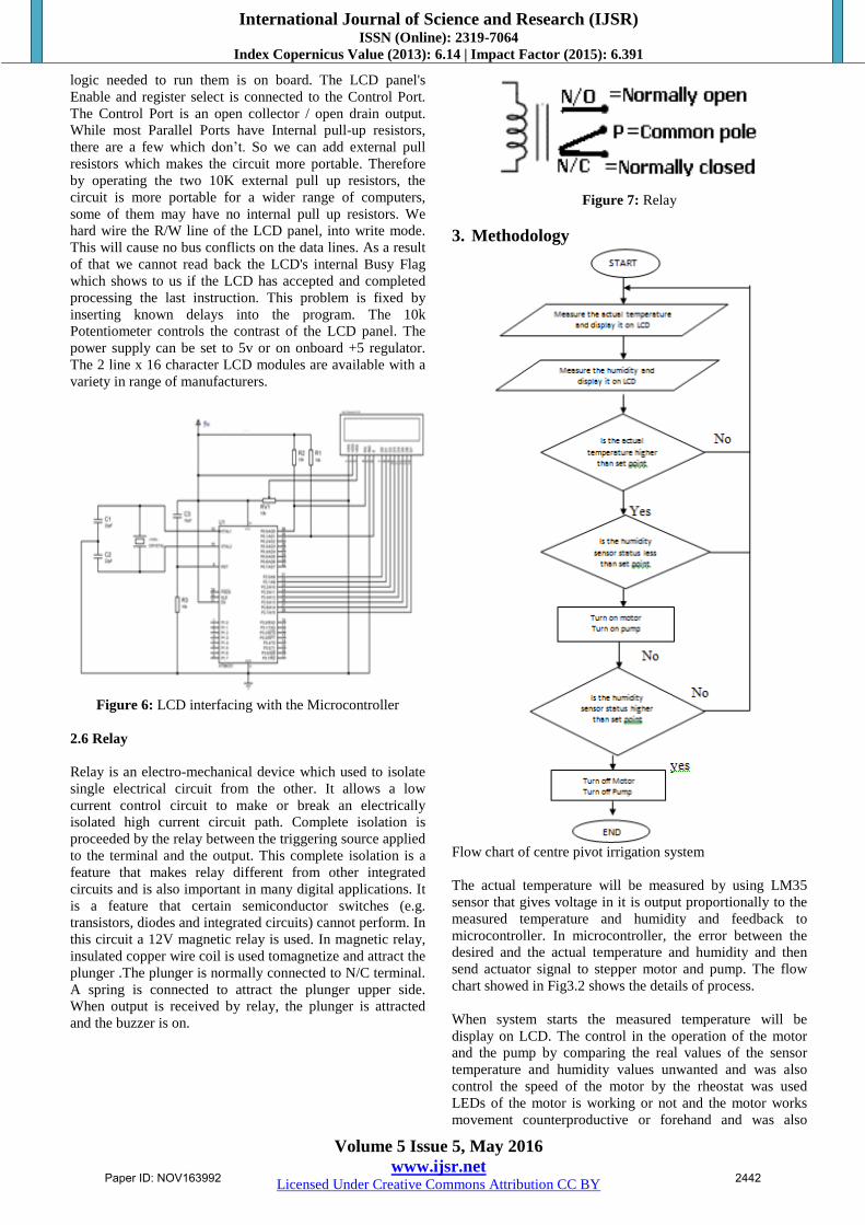
3. Methodology
Flow chart of centre pivot irrigation system
The actual temperature will be measured by using LM35
sensor that gives voltage in it is output proportionally to the
measured temperature and humidity and feedback to
microcontroller. In microcontroller, the error between the
desired and the actual temperature and humidity and then
send actuator signal to stepper motor and pump. The flow
chart showed in Fig3.2 shows the details of process.
When system starts the measured temperature will be
display on LCD. The control in the operation of the motor
and the pump by comparing the real values of the sensor
temperature and humidity values unwanted and was also
control the speed of the motor by the rheostat was used
LEDs of the motor is working or not and the motor works
movement counterproductive or forehand and was also
Paper ID: NOV163992 2442

International Journal of Science and Research (IJSR) ISSN (Online): 2319-7064
Index Copernicus Value (2013): 6.14 | Impact Factor (2015): 6.391
Volume 5 Issue 5, May 2016
www.ijsr.net Licensed Under Creative Commons Attribution CC BY
controlled by the computer using serial communication
using Max232 and Rs232.
Is used to the idea of the soil moisture sensor which is
interfaced with microcontrollers and the other part is
connected with wires to measure moisture and are placed
two wires in the soil so that when the water flows on the
soil, Microcontroller checks the output of soil moisture
sensor. If the water level is low then microcontroller will on
the relay that will switch on the Motor and Water pump.
Then when the water level is high it will switch off Motor
and the Pump.
4. Result
4.1 Significant Result
The implementation of this project has result in two ultimate
circuits, the one that represents the simulation of the system
and discussed in Figure 4.2 and the hardware circuit of the
system.
4.2 Simulation Result
As shown in Figure 4.1 the simulation result for the system
is viewed after the program code was developed and the
loaded into the PIC, MCU, commands testing operation was
started the illuminating LEDs are indicatory response to the
commands.
Figure 4.1: Basic Irrigation System Simulation
4.3 Hardware Result and Discussion
The temperature control system has been successfully
implemented for hardware construction and tests have been
carried out after the program loaded into pic microcontroller
to verify that the circuit functions correctly and probably as
shown in Fig 4.2. This section briefly discusses the result
obtained during the project development and simulated test.
Figure 4.2: Hardware Circuit
4.3.1 Simulation Part
The programming has been found to be working
successfully. It has been simulated and tested many times at
different set point using proteus simulation package and lab
view simulation package. In this situation motor direction is
forward and the pump is on as the LEDs shown that in
Figure 4.3.
Figure 4.3: Basic Irrigation System Simulation in Forward
Direction
In this situation when motor direction switch is pressed the
stepper motor changes it is direction to the reverse one as
shown in Figure 4.4.
Paper ID: NOV163992 2443

International Journal of Science and Research (IJSR) ISSN (Online): 2319-7064
Index Copernicus Value (2013): 6.14 | Impact Factor (2015): 6.391
Volume 5 Issue 5, May 2016
www.ijsr.net Licensed Under Creative Commons Attribution CC BY
Figure 4.4: Basic Irrigation System Simulation in Reverse
Direction
Lab View package is used to monitor the temperature degree
and the status of both motor and pump using LEDs. Figure
4.5 represents Lab View Front Panel.
Figure 4.5: Lab View Front Panel
4.3.2 Hardware Part
Once the program has been loaded into microcontroller, the
overall hardware design has been tested as different
temperature degrees and it found work correctly and probably
as scheduled as shown in Figure 4.6.
Figure 4.6: Hardware Circuit Testing
5. Conclusion
The center pivot irrigation system has been controlled
automatically through microcontroller by building a system
of two separated parts, the flexible part counts on high level
languages and the solid part relies on an electronic and
mechanical parts. And then connect the solid part with the
graphical part using serial port (Rs232) so as to show the
information you needed to know from the field, which is
electronically controlled using push buttons and find out the
status of each of the motor, pump and the temperature.
6. Future Recommendation
1) Using PLC instead of microcontroller.
2) Using wireless communication.
References
[1] Mader, Shelli (May 25, 2010),"Center pivot irrigation
revolutionizes agriculture", The Fence Post Magazine.
[2] http://en.wikipedia.org/wiki/Stepper_motor 1&2 was on
Friday 3/1/2013 19:00 pm
[3] Liptak, Bela G. (2005). Instrument Engineers'
Handbook: Process Control and Optimization
[4] http://www.imagesco.com/articles/picstepper/02.html
[5] http://en.wikipedia.org/wiki/Microcontroller
[6] http://www.radioelectronics.com/info/telecommunicatio
ns_networks/rs232/eia-rs232-c-d-standards.php
[7] http://en.wikipedia.org/wiki/rs232
[8] www.sherline.com
[9] http://www ian.umces.edu
[10] Texas Instruments, Copyright © 2011, Texas
Instruments Incorporated
[11] Mason, C. R. "Art & Science of Protective Relaying-
Chapter 2, GE Consumer & Electrical". Retrieved
October 9, 2011.
[12] Zocholl, Stan, AC Motor Protection. Schweitzer
Engineering Laboratories, Inc. (2003).
Paper ID: NOV163992 2444